EP3809624B1 - Décodage de canal de commande à bande étroite - Google Patents
Décodage de canal de commande à bande étroite Download PDFInfo
- Publication number
- EP3809624B1 EP3809624B1 EP20214731.0A EP20214731A EP3809624B1 EP 3809624 B1 EP3809624 B1 EP 3809624B1 EP 20214731 A EP20214731 A EP 20214731A EP 3809624 B1 EP3809624 B1 EP 3809624B1
- Authority
- EP
- European Patent Office
- Prior art keywords
- control channel
- narrowband
- crs
- base station
- resources
- Prior art date
- Legal status (The legal status is an assumption and is not a legal conclusion. Google has not performed a legal analysis and makes no representation as to the accuracy of the status listed.)
- Active
Links
- 238000004891 communication Methods 0.000 claims description 99
- 230000006854 communication Effects 0.000 claims description 99
- 238000000034 method Methods 0.000 claims description 92
- 238000013507 mapping Methods 0.000 claims description 15
- 238000004590 computer program Methods 0.000 claims description 2
- 230000006870 function Effects 0.000 description 39
- 101150111571 mreg gene Proteins 0.000 description 23
- 230000005540 biological transmission Effects 0.000 description 22
- 238000010586 diagram Methods 0.000 description 17
- 238000005516 engineering process Methods 0.000 description 13
- 230000008569 process Effects 0.000 description 9
- 239000000969 carrier Substances 0.000 description 6
- 125000004122 cyclic group Chemical group 0.000 description 6
- 238000012544 monitoring process Methods 0.000 description 6
- 230000002776 aggregation Effects 0.000 description 5
- 238000004220 aggregation Methods 0.000 description 5
- 230000008901 benefit Effects 0.000 description 5
- 238000012545 processing Methods 0.000 description 5
- 230000003287 optical effect Effects 0.000 description 3
- 230000008520 organization Effects 0.000 description 3
- 230000001360 synchronised effect Effects 0.000 description 3
- 230000001427 coherent effect Effects 0.000 description 2
- 239000000835 fiber Substances 0.000 description 2
- 230000007774 longterm Effects 0.000 description 2
- 238000010295 mobile communication Methods 0.000 description 2
- 239000002245 particle Substances 0.000 description 2
- 230000000737 periodic effect Effects 0.000 description 2
- 230000011664 signaling Effects 0.000 description 2
- 238000001228 spectrum Methods 0.000 description 2
- 241000282412 Homo Species 0.000 description 1
- 230000006978 adaptation Effects 0.000 description 1
- 238000013475 authorization Methods 0.000 description 1
- 230000006399 behavior Effects 0.000 description 1
- 230000007175 bidirectional communication Effects 0.000 description 1
- 230000001413 cellular effect Effects 0.000 description 1
- 239000003795 chemical substances by application Substances 0.000 description 1
- 238000010276 construction Methods 0.000 description 1
- 230000001351 cycling effect Effects 0.000 description 1
- 230000001419 dependent effect Effects 0.000 description 1
- 238000013461 design Methods 0.000 description 1
- 238000012423 maintenance Methods 0.000 description 1
- 230000000116 mitigating effect Effects 0.000 description 1
- 238000012986 modification Methods 0.000 description 1
- 230000004048 modification Effects 0.000 description 1
- 238000005192 partition Methods 0.000 description 1
- 230000010363 phase shift Effects 0.000 description 1
- 230000002250 progressing effect Effects 0.000 description 1
- 230000000750 progressive effect Effects 0.000 description 1
- 230000002441 reversible effect Effects 0.000 description 1
- 238000005070 sampling Methods 0.000 description 1
- 230000011218 segmentation Effects 0.000 description 1
- 238000012546 transfer Methods 0.000 description 1
- 208000037918 transfusion-transmitted disease Diseases 0.000 description 1
- XLYOFNOQVPJJNP-UHFFFAOYSA-N water Substances O XLYOFNOQVPJJNP-UHFFFAOYSA-N 0.000 description 1
Images


Classifications
-
- H—ELECTRICITY
- H04—ELECTRIC COMMUNICATION TECHNIQUE
- H04L—TRANSMISSION OF DIGITAL INFORMATION, e.g. TELEGRAPHIC COMMUNICATION
- H04L5/00—Arrangements affording multiple use of the transmission path
- H04L5/003—Arrangements for allocating sub-channels of the transmission path
- H04L5/0053—Allocation of signaling, i.e. of overhead other than pilot signals
-
- H—ELECTRICITY
- H04—ELECTRIC COMMUNICATION TECHNIQUE
- H04L—TRANSMISSION OF DIGITAL INFORMATION, e.g. TELEGRAPHIC COMMUNICATION
- H04L5/00—Arrangements affording multiple use of the transmission path
- H04L5/003—Arrangements for allocating sub-channels of the transmission path
- H04L5/0048—Allocation of pilot signals, i.e. of signals known to the receiver
- H04L5/0051—Allocation of pilot signals, i.e. of signals known to the receiver of dedicated pilots, i.e. pilots destined for a single user or terminal
-
- H—ELECTRICITY
- H04—ELECTRIC COMMUNICATION TECHNIQUE
- H04L—TRANSMISSION OF DIGITAL INFORMATION, e.g. TELEGRAPHIC COMMUNICATION
- H04L5/00—Arrangements affording multiple use of the transmission path
- H04L5/0001—Arrangements for dividing the transmission path
- H04L5/0003—Two-dimensional division
- H04L5/0005—Time-frequency
-
- H—ELECTRICITY
- H04—ELECTRIC COMMUNICATION TECHNIQUE
- H04L—TRANSMISSION OF DIGITAL INFORMATION, e.g. TELEGRAPHIC COMMUNICATION
- H04L5/00—Arrangements affording multiple use of the transmission path
- H04L5/003—Arrangements for allocating sub-channels of the transmission path
- H04L5/0048—Allocation of pilot signals, i.e. of signals known to the receiver
- H04L5/005—Allocation of pilot signals, i.e. of signals known to the receiver of common pilots, i.e. pilots destined for multiple users or terminals
Definitions
- the following relates generally to wireless communication and more specifically to narrowband control channel decoding.
- Wireless communications systems are widely deployed to provide various types of communication content such as voice, video, packet data, messaging, broadcast, and so on. These systems may be multiple-access systems capable of supporting communication with multiple users by sharing the available system resources (e.g. , time, frequency, and power). Examples of such multiple-access systems include code division multiple access (CDMA) systems, time division multiple access (TDMA) systems, frequency division multiple access (FDMA) systems, and orthogonal frequency division multiple access (OFDMA) systems, (e.g. , an LTE system).
- CDMA code division multiple access
- TDMA time division multiple access
- FDMA frequency division multiple access
- OFDMA orthogonal frequency division multiple access
- a wireless multiple-access communications system may include a number of base stations, each simultaneously supporting communication for multiple communication devices, which may be otherwise known as user equipment (UEs).
- a base station may communicate with the communication devices on downlink channels (e.g., for transmissions from a base station to a UE) and uplink channels (e.g. , for transmissions from a UE to a base station).
- certain UEs may have limited operating capabilities.
- device UE may not be designed for broadband communications. This may interfere with the ability of the UE to receive certain control information from a base station.
- WO 2013/129884 A1 discloses a method for transmitting downlink data in a wireless communication system.
- a base station generates a downlink sub-frame comprising: a first control channel for a first cell having a first frequency band; and a second control channel for a second cell having a second frequency band including a part of the first frequency band.
- the base station transmits the downlink data through the downlink sub-frame.
- a user equipment may establish a connection with another wireless node, such as a base station or UE.
- the connection may include a narrowband control region of a wideband system.
- the UE may identify a set of subframes during which to monitor a demodulation reference signal (DM-RS) for decoding a control channel.
- DM-RS demodulation reference signal
- the identified subframes or resource blocks may, for example, have the same precoding.
- the UE may decode the control channel (e.g. , a physical downlink control channel (PDCCH)) using the DM-RS.
- PDCH physical downlink control channel
- the UE may additionally or alternatively decode the control channel using a cell-specific reference signal (CRS).
- CRS cell-specific reference signal
- the UE may, in some examples, determine- e.g. , via signaling received from another node-resources to exclude from the control channel. For instance, the UE may determine that the narrowband region includes a portion of control region for broadband communication, and the UE may exclude those resources.
- a method of wireless communication includes identifying a plurality of subframes during which to monitor a demodulation reference signal (DM-RS) for decoding a control channel associated with a node, wherein the control channel comprises a narrowband region of a wideband system, and wherein the plurality of subframes have a same precoding for the DM-RS and decoding the control channel based at least in part on the DM-RS.
- DM-RS demodulation reference signal
- the apparatus includes means for identifying a plurality of subframes during which to monitor a demodulation reference signal (DM-RS) for decoding a control channel associated with a node, wherein the control channel comprises a narrowband region of a wideband system, and wherein the plurality of subframes have a same precoding for the DM-RS and means for decoding the control channel based at least in part on the DM-RS.
- DM-RS demodulation reference signal
- the apparatus includes a processor, memory in electronic communication with the processor, and instructions stored in the memory.
- the instructions may be operable, when executed by the processor, to cause the apparatus to identify a plurality of subframes during which to monitor a demodulation reference signal (DM-RS) for decoding a control channel associated with a node, wherein the control channel comprises a narrowband region of a wideband system, and wherein the plurality of subframes have a same precoding for the DM-RS and decode the control channel based at least in part on the DM-RS.
- DM-RS demodulation reference signal
- a non-transitory computer readable medium for wireless communication stores code for wireless communication, and the code may include instructions executable to identify a plurality of subframes during which to monitor a demodulation reference signal (DM-RS) for decoding a control channel associated with a node, where the control channel comprises a narrowband region of a wideband system, and where the plurality of subframes have a same precoding for the DM-RS and decode the control channel based at least in part on the DM-RS.
- DM-RS demodulation reference signal
- Some examples of the method, apparatus, or non-transitory computer-readable medium described above may further include processes, features, means, or instructions for identifying two or more resource blocks (RBs) that have the same precoding within the narrowband region.
- RBs resource blocks
- Some examples of the method, apparatus, or non-transitory computer-readable medium described above may further include processes, features, means, or instructions for excluding resources of the narrowband region that comprise a control region for broadband communications from the control channel.
- control channel comprises a control channel element (CCE) that comprises a set of resource element groups (REGs).
- CCE control channel element
- REGs resource element groups
- each REG of the set of REGs is distributed in time and frequency during the plurality of subframes within the narrowband region.
- each REG of the set of REGs excludes resource elements that comprise DM-RS.
- each REG of the set of REGs excludes resource elements that comprise a cell-specific reference signal (CRS).
- CRS cell-specific reference signal
- a single precoder is applied for each physical resource block pair of the control channel.
- two or more precoders are applied to resources with each physical resource block pair of the control channel.
- control channel is decoded based at least in part on a cell-specific reference signal (CRS).
- CRS cell-specific reference signal
- a user equipment may establish a connection with another wireless node, such as a base station or UE.
- the connection may include a narrowband control region of a wideband system, and the UE may decode a control channel received in the narrowband control region using demodulation reference signals (DM-RS) or cell-specific reference signals (CRS), or both, as described herein.
- DM-RS demodulation reference signals
- CRS cell-specific reference signals
- Some of the example wireless systems described herein provide for automated communication known as Machine-to-Machine (M2M) communication or Machine Type Communication (MTC).
- M2M or MTC may refer to technologies or devices, such as UEs that communicate without human intervention.
- UEs may operate according to certain constraints (e.g., narrowband operation) even though the UEs may be capable of more complex operation. While some devices, such as MTC devices, may have limited capabilities and may operate accordingly.
- LTE Long Term Evolution
- MTC device having limited bandwidth capability (or another device with similar capabilities) may be referred to as a category 0 device.
- MTC devices may have reduced peak data rates (e.g., a maximum transport block size may be 1000 bits). Additionally, an MTC device may have rank 1 transmission and one antenna for receiving. This may limit an MTC device to half-duplex communication ( i.e. , the device may not be capable of simultaneously transmitting and receiving). If an MTC device is half-duplex, it may have relaxed switching time (e.g. , from transmission (Tx) to reception (Rx) or vice versa). For example, a nominal switching time for a non-MTC device may be 20 ⁇ s while a switching time for an MTC device may be 1ms.
- MTC enhancements in a wireless system may allow narrowband MTC devices to effectively operate within wider system bandwidth operations (e.g. , 1.4/3/5/10/15/20 MHz).
- an MTC device may support 1.4 MHz bandwidth ( i.e. , 6 resources blocks).
- coverage enhancements of such MTC devices may be achieved by power boosting of ( e.g. , of up to 15dB).
- a UE which may be an MTC device or another UE that supports narrowband operation, may establish a connection with another wireless node using a narrowband control region of a wideband system.
- the UE may identify a set of resources for a narrowband or MTC physical DL control channel (mPDCCH) within the narrowband control region based on a resource element indexing configuration associated with a cell-specific reference signal (CRS) based demodulation scheme.
- CRS cell-specific reference signal
- the UE may then receive the mPDCCH using the identified resources and demodulate the mPDCCH based on the CRS demodulation scheme.
- the resource element indexing configuration may exclude the resource elements used for CRS.
- the resource element indexing configuration may exclude the resource elements used for demodulation reference signals (DM-RS).
- DM-RS resource elements may be indexed separately.
- a UE or a base station may determine which indexing configuration to use based on coverage and traffic consideration. For example, a UE without coverage enhancement needs may employ an alternative in which only CRS based modulation is used. On the other hand, a UE with coverage enhancement needs may use an alternative in which demodulation is based on both CRS and DM-RS.
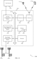
- FIG. 1 illustrates an example of a wireless communications system 100 in accordance with various aspects of the present disclosure.
- the system 100 includes base stations 105, at least one UE 115, and a core network 130.
- the core network 130 may provide user authentication, access authorization, tracking, internet protocol (IP) connectivity, and other access, routing, or mobility functions.
- IP internet protocol
- the base stations 105 interface with the core network 130 through backhaul links 132 (e.g., S1, etc.).
- the base stations 105 may perform radio configuration and scheduling for communication with the UEs 115, or may operate under the control of a base station controller (not shown).
- the base stations 105 may communicate, either directly or indirectly ( e.g. , through core network 130), with one another over backhaul links 134 ( e.g., X1, etc.), which may be wired or wireless communication links.
- backhaul links 134 e.g., X1, etc.
- the base stations 105 may wirelessly communicate with the UEs 115 via one or more base station antennas. Each of the base stations 105 may provide communication coverage for a respective geographic coverage area 110.
- base stations 105 may be referred to as a base transceiver station, a radio base station, an access point, a radio transceiver, a NodeB, eNodeB (eNB), Home NodeB, a Home eNodeB, or some other suitable terminology.
- the geographic coverage area 110 for a base station 105 may be divided into sectors making up only a portion of the coverage area (not shown).
- the wireless communications system 100 may include base stations 105 of different types (e.g. , macro or small cell base stations). There may be overlapping geographic coverage areas 110 for different technologies
- the wireless communications system 100 is an LTE/LTE-Advanced (LTE-A) network.
- LTE/LTE-A networks the term evolved node B (eNB) may be generally used to describe the base stations 105, while the term UE may be generally used to describe the UEs 115, which may include MTC devices.
- the wireless communications system 100 may be a heterogeneous LTE/LTE-A network in which different types of eNBs provide coverage for various geographical regions. For example, each eNB or base station 105 may provide communication coverage for a macro cell, a small cell, or other types of cell.
- cell is a 3GPP term that can be used to describe a base station, a carrier, or component carrier associated with a base station, or a coverage area (e.g., sector, etc.) of a carrier or base station, depending on context.
- a macro cell generally covers a relatively large geographic area (e.g ., several kilometers in radius) and may allow unrestricted access by UEs 115 with service subscriptions with the network provider.
- a small cell is a lower-powered base station, as compared with a macro cell, that may operate in the same or different ( e.g. , licensed, unlicensed, etc. ) frequency bands as macro cells.
- Small cells may include pico cells, femto cells, and micro cells according to various examples.
- a pico cell for example, may cover a small geographic area and may allow unrestricted access by UEs 115 with service subscriptions with the network provider.
- a femto cell may also cover a small geographic area (e.g.
- An eNB for a macro cell may be referred to as a macro eNB.
- An eNB for a small cell may be referred to as a small cell eNB, a pico eNB, a femto eNB, or a home eNB.
- An eNB may support one or multiple ( e.g. , two, three, four, and the like) cells ( e.g. , component carriers).
- the wireless communications system 100 may support synchronous or asynchronous operation.
- the base stations 105 may have similar frame timing, and transmissions from different base stations 105 may be approximately aligned in time.
- the base stations 105 may have different frame timing, and transmissions from different base stations 105 may not be aligned in time.
- the techniques described herein may be used for either synchronous or asynchronous operations.
- the communication networks may be packet-based networks that operate according to a layered protocol stack and data in the user plane may be based on the IP.
- a radio link control (RLC) layer may perform packet segmentation and reassembly to communicate over logical channels.
- a medium access control (MAC) layer may perform priority handling and multiplexing of logical channels into transport channels.
- the MAC layer may also use hybrid automatic repeat request (HARQ) to provide retransmission at the MAC layer to improve link efficiency.
- the radio resource control (RRC) protocol layer may provide establishment, configuration, and maintenance of an RRC connection between a UE 115 and the base stations 105.
- the RRC protocol layer may also be used for core network 130 support of radio bearers for the user plane data.
- the transport channels may be mapped to physical channels.
- the UEs 115 may be dispersed throughout the wireless communications system 100, and each UE 115 may be stationary or mobile.
- a UE 115 may also include or be referred to by those skilled in the art as a mobile station, a subscriber station, a mobile unit, a subscriber unit, a wireless unit, a remote unit, a mobile device, a wireless device, a wireless communications device, a remote device, a mobile subscriber station, an access terminal, a mobile terminal, a wireless terminal, a remote terminal, a handset, a user agent, a mobile client, a client, or some other suitable terminology.
- a UE 115 may be a cellular phone, a personal digital assistant (PDA), a wireless modem, a wireless communication device, a handheld device, a tablet computer, a laptop computer, a cordless phone, a wireless local loop (WLL) station, or the like.
- PDA personal digital assistant
- a UE may be able to communicate with various types of base stations and network equipment including macro eNBs, small cell eNBs, relay base stations, and the like.
- Automated wireless devices may include those implementing Machine-to-Machine (M2M) communication or Machine Type Communication (MTC), which may allow devices to communicate with one another or a base station without human intervention.
- M2M or MTC may refer to communications from devices that integrate sensors or meters to measure or capture information and relay that information to a central server or application program that can make use of the information or present the information to humans interacting with the program or application.
- Some UEs 115 may be MTC devices, such as those designed to collect information or enable automated behavior of machines.
- MTC devices examples include smart metering, inventory monitoring, water level monitoring, equipment monitoring, healthcare monitoring, wildlife monitoring, weather and geological event monitoring, fleet management and tracking, remote security sensing, physical access control, and transaction-based business charging.
- An MTC device may operate using half-duplex (one-way) communications at a reduced peak rate.
- MTC devices may also be configured to enter a power saving "deep sleep" mode when not engaging in active communications.
- the UEs 115 are category 0 UEs (e.g. , narrowband MTC devices).
- the communication links 125 shown in wireless communications system 100 may include uplink (UL) transmissions from a UE 115 to a base station 105, or downlink (DL) transmissions, from a base station 105 to a UE 115.
- the downlink transmissions may also be called forward link transmissions while the uplink transmissions may also be called reverse link transmissions.
- Each communication link 125 may include one or more carriers, where each carrier may be a signal made up of multiple sub-carriers ( e.g. , waveform signals of different frequencies) modulated according to the various radio technologies described above.
- Each modulated signal may be sent on a different sub-carrier and may carry control information (e.g. , reference signals, control channels, etc. ), overhead information, user data, etc.
- the communication links 125 may include a narrowband control region.
- a PDCCH e.g. , mPDCCH
- the communication links 125 may transmit bidirectional communications using frequency division duplex (FDD) (e.g. , using paired spectrum resources) or time division duplex (TDD) operation ( e.g. , using unpaired spectrum resources).
- FDD frequency division duplex
- TDD time division duplex
- Frame structures may be defined for FDD (e.g., frame structure type 1) and TDD (e.g. , frame structure type 2).
- a base station 105 may insert periodic pilot symbols such as CRS to improve the efficiency of wireless communication links 125 ( e.g. , to aid UEs 115 in channel estimation and coherent demodulation).
- Control channels such as a PDCCH, may be demodulated based on CRS- e.g ., according to a CRS-based demodulation scheme.
- CRS may include one of 504 different cell identities. They may be modulated using quadrature phase shift keying (QPSK) and power boosted ( e.g. , transmitted at 6dB higher than the surrounding data elements) to make them resilient to noise and interference.
- QPSK quadrature phase shift keying
- CRS may be embedded in 4 to 24 resource elements in each resource block based on the number of antenna ports or layers (up to 4) of the receiving UEs 115.
- demodulation reference signal which may also be referred to as UE-specific reference signals, may be directed toward specific UEs 115 and may be transmitted only on resource blocks assigned to those UEs115.
- DM-RS may include signals on 24 resource elements in each resource block in which they are transmitted. In some cases, two sets of DM-RS may be transmitted in adjoining resource elements.
- additional reference signals known as channel state information reference signals (CSI-RS) may be included to aid in generating channel state information (CSI).
- CSI-RS channel state information reference signals
- CSI-RS channel state information reference signals
- Wireless communication links 125 may also be established between UEs 115 in a configuration known as device-to-device (D2D) communications.
- D2D device-to-device
- One or more of a group of UEs 115 utilizing D2D communications may be within the coverage area 110 of a cell. Other UEs 115 in such a group may be outside the coverage area 110 of a cell, or otherwise unable to receive transmissions from a base station 105.
- groups of UEs 115 communicating via D2D communications may utilize a one-to-many (1:M) system in which each UE 115 transmits to every other UE 115 in the group.
- a base station 105 facilitates the scheduling of resources for D2D communications.
- D2D communications are carried out independent of a base station 105.
- a device within a D2D implementation may be referred to as a node.
- base stations 105 or UEs 115 may include multiple antennas for employing antenna diversity schemes to improve communication quality and reliability between base stations 105 and UEs 115. Additionally or alternatively, base stations 105 or UEs 115 may employ multiple input multiple output (MIMO) techniques that may take advantage of multi-path environments to transmit multiple spatial layers carrying the same or different coded data.
- MIMO multiple input multiple output
- Wireless communications system 100 may support operation on multiple cells or carriers, a feature which may be referred to as carrier aggregation (CA) or multicarrier operation.
- a carrier may also be referred to as a component carrier (CC), a layer, a channel, etc.
- CC component carrier
- the terms “carrier,” “component carrier,” “cell,” and “channel” may be used interchangeably herein.
- a UE 115 may be configured with multiple downlink CCs and one or more uplink CCs for carrier aggregation.
- Carrier aggregation may be used with both FDD and TDD component carriers.
- LTE systems may utilize orthogonal frequency division multiple access (OFDMA) on the DL and single carrier frequency division multiple access (SC-FDMA) on the UL.
- OFDMA and SC-FDMA partition the system bandwidth into multiple (K) orthogonal subcarriers, which are also commonly referred to as tones or bins.
- K may be modulated with data.
- the spacing between adjacent subcarriers may be fixed, and the total number of subcarriers (K) may be dependent on the system bandwidth.
- K may be equal to 72, 180, 300, 600, 900, or 1200 with a subcarrier spacing of 15 kilohertz (KHz) for a corresponding system bandwidth (with guard band) of 1.4, 3, 5, 10, 15, or 20 megahertz (MHz), respectively.
- KHz 15 kilohertz
- the system bandwidth may also be partitioned into sub-bands.
- a sub-band may cover 1.08 MHz, and there may be 1, 2, 4, 8, or 16 sub-bands.
- a frame structure may also be used to organize physical resources.
- SFN system frame number
- Each frame may include ten 1ms subframes numbered from 0 to 9.
- a subframe may be further divided into two .5ms slots, each of which contains 6 or 7 modulation symbol periods (depending on the length of the cyclic prefix prepended to each symbol). Excluding the cyclic prefix, each symbol contains 2048 sample periods.
- the subframe may be the smallest scheduling unit, also known as a transmission time interval (TTI).
- TTI transmission time interval
- a TTI may be shorter than a subframe or may be dynamically selected (e.g ., in short TTI bursts or in selected component carriers using short TTIs).
- a resource element may consist of one symbol period and one subcarrier (a 15Khz frequency range).
- a resource block may contain 12 consecutive subcarriers in the frequency domain and, for a normal cyclic prefix in each OFDM symbol, 7 consecutive OFDM symbols in the time domain (1 slot), or 84 resource elements.
- Some REs may include DL reference signals (DL-RS).
- the DL-RS may include a CRS and a UE-specific RS (UE-RS) or demodulation reference signals (DM-RS).
- UE-RS UE-specific RS
- DM-RS demodulation reference signals
- reference signals may be transmitted on the resource blocks associated with PDSCH.
- the number of bits carried by each RE may depend on the modulation scheme (the configuration of symbols that may be selected during each symbol period). Thus, the more resource blocks that a UE receives and the higher the modulation scheme, the higher the data rate may be for the UE.
- Data may be divided into logical channels, transport channels, and physical layer channels. Channels may also be classified into Control Channels and Traffic Channels.
- DL physical channels may include physical broadcast channel (PBCH) for broadcast information, physical control format indicator channel (PCFICH) for control format information, PDCCH for control and scheduling information, physical HARQ indicator channel (PHICH) for HARQ status messages, physical downlink shared channel (PDSCH) for user data and physical multicast channel (PMCH) for multicast data.
- UL physical channels may include physical random access channel (PRACH) for access messages, physical uplink control channel (PUCCH) for control data, and physical uplink shared channel (PUSCH) for user data.
- PRACH physical random access channel
- PUCCH physical uplink control channel
- PUSCH physical uplink shared channel
- PDCCH carries downlink control information (DCI) in control channel elements (CCEs), which may consist of nine logically contiguous resource element groups (REGs) located in the first few symbols of a resource block, where each REG contains 4 REs.
- CCEs control channel elements
- REGs resource element groups located in the first few symbols of a resource block, where each REG contains 4 REs.
- a CCE e.g., a CCE designed for MTC or narrowband communications
- MTC devices or other UEs 115 may use an evolved physical downlink control channel (ePDCCH) based on DM-RS or MTC PDCCH (mPDCCH) based on CRS, both of which may facilitate coordinated multi-point (CoMP), DL multiple-input-multiple-output (MIMO) enhancements, and inter-cell interference coordination (ICIC) or further enhanced ICIC.
- ePDCCH evolved physical downlink control channel
- mPDCCH MTC PDCCH
- CRS CRS
- CoMP coordinated multi-point
- MIMO DL multiple-input-multiple-output
- IMC inter-cell interference coordination
- an ePDCCH or mPDCCH may span an entire subframe using selected subcarriers (e.g., it may be frequency-division multiplexed (FDM)).
- FDM frequency-division multiplexed
- DM-RS based ePDCCH may be supported and in other cases CRS based PDCCH or mPDCCH may be supported.
- the ePDCCH or mPDCCH may be UE-specifically configured (e.g., each UE may be configured to monitor a different set of resources).
- a localized mode a single precoder may be applied for each physical resource block (PRB) pair, such as of a control channel.
- PRB physical resource block
- distributed mode two or more precoders may be applied to, or may cycle through, the allocated resources within each PRB pair, such as of a control channel.
- the DCI included in a PDCCH, ePDCCH, or mPDCCH may include information regarding DL scheduling assignments, UL resource grants, transmission scheme, UL power control, HARQ information, modulation and coding scheme (MCS) and other information.
- the size and format of the DCI messages can differ depending on the type and amount of information that is carried by the DCI. For example, if spatial multiplexing is supported, the size of the DCI message may be large compared to contiguous frequency allocations. Similarly, for a system that employs MIMO, the DCI may include additional signaling information. DCI size and format may also depend on the amount of information, as well as factors such as bandwidth, the number of antenna ports, and duplexing mode.
- PDCCH can carry DCI messages associated with multiple users, and each UE 115 may decode the DCI messages that are intended for it. For example, each UE 115 may be assigned a cell radio network temporary identity (C-RNTI) and cyclic redundancy check (CRC) bits attached to each DCI may be scrambled based on the C-RNTI.
- C-RNTI cell radio network temporary identity
- CRC cyclic redundancy check
- a limited set of CCE locations can be specified for DCI associated with a specific UE 115.
- CCEs may be grouped ( e.g. , in groups of 1, 2, 4 and 8 CCEs), and a set of CCE locations in which the user equipment may find relevant DCI may be specified. These CCEs may be known as a search space.
- the search space can be partitioned into two regions: a common CCE region or search space and a UE-specific (dedicated) CCE region or search space.
- the common CCE region may be monitored by all UEs served by a base station 105 and may include information such as paging information, system information, random access procedures, and the like.
- the UE-specific search space may include user-specific control information.
- CCEs may be indexed, and the common search space may start from CCE 0.
- the starting index for a UE specific search space may depend on the C-RNTI, the subframe index, the CCE aggregation level and a random seed.
- a UE 115 may attempt to decode DCI by performing a process known as a blind decode, during which search spaces are randomly decoded until the DCI is detected. During a blind decode, the UE 115 may attempt descramble all potential DCI messages using its C-RNTI, and perform a CRC check to determine whether the attempt was successful.
- a blind decode the UE 115 may attempt descramble all potential DCI messages using its C-RNTI, and perform a CRC check to determine whether the attempt was successful.
- a UE 115 may establish a connection with another wireless node, such as a base station 105 or another UE.
- the connection may include a narrowband control region.
- the UE 115 may identify a set of resources for an mPDCCH within the narrowband control region based on an RE indexing configuration associated with a CRS based demodulation scheme.
- the UE 115 may then receive the mPDCCH using the identified resources and demodulate the mPDCCH based on the CRS based demodulation scheme.
- the RE indexing configuration may exclude the REs used for CRS.
- the RE indexing configuration may exclude the REs used for DM-RS.
- DM-RS REs may be indexed separately.
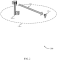
- FIG. 2 illustrates an example of a wireless communications system 200 for CRS based control channel element in accordance with various aspects of the present disclosure.
- Wireless communications system 200 may include a UE 115-a, which may be an example of a UE 115 described above with reference to FIG. 1 .
- UE 115-a is an MTC device.
- Wireless communications system 200 may also include a base station 105-a, which may be an example of a base station 105 described above with reference to FIG. 1 .
- Base station 105-a may transmit control information and data to any UE 115 within its coverage area 110-a via downlink 205, as generally described with respect to FIG. 1 .
- downlink 205 may be a narrowband connection that may not utilize the whole range of frequency tones of the cell.
- the narrowband region may be selected based on the capabilities of the UE 115-a.
- the actions performed by base station 105-a may be performed by another UE 115 (not shown) according to D2D operations.
- Base station 105-a may thus be referred to as a node; and other nodes, including certain UEs, of a system may perform the same or similar functions as base station 105-a.
- UE 115-a may receive control information via a narrowband control region that may utilize selected frequency tones, and may extend through each symbol period of a subframe.
- the control information may utilize resources that are identified by an indexing scheme associated with CRS based demodulation.
- UE 115-a may use the CRS (and, in some cases, DM-RS) transmitted by base station 105-a for coherent demodulation of data conveyed by downlink 205.
- UE 115-a may establish a connection with base station 105-a including downlink 205 and receive data via downlink 205 utilizing a narrowband control region.
- UE 115-a may identify a set of resources for a PDCCH (e.g., an mPDCCH designed for use by MTC devices) within the narrowband control region based on an RE indexing configuration associated with a CRS based demodulation scheme.
- UE 115-a may then receive the PDCCH using the identified resources and demodulate the PDCCH based on a CRS.
- the RE indexing configuration may exclude the REs used for CRS.
- the RE indexing configuration may exclude the REs used for DM-RS.
- DM-RS REs may be indexed separately.
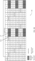
- FIG. 3A illustrates an example of an indexing configuration 301 for CRS based control channel element in accordance with various aspects of the present disclosure.
- Indexing configuration 301 may represent aspects of downlink 205 described above with reference to FIG. 2
- Indexing configuration 301 may illustrate a configuration of 14 symbol periods (1 subframe) in the time domain and 12 tones (1 RB) in the frequency domain. Each RE may correspond to the time and frequency resource included in one symbol period on one tone.
- Indexing configuration 301 may include indexed control region REs 305-a and non-indexed CRS REs 310, whose configuration may be based on the number of antennas and layers used in the communication. In some cases the non-indexed REs may correspond to a maximum CRS configuration ( i.e. , for a maximum number of antenna ports).
- the REs of indexing configuration 301 may be grouped into MTC resource element groups (mREGs) based on the indices. In some case, 9 REs may make up one mREG.
- a group of 4 mREGs i.e., 36 REs
- the REs of indexing configuration 301 may be divided into 16 mREGs, which may be distinguished according to their indices. For example, all of the indexed control region REs 305-a with index 0 may correspond to a single mREG. As shown in indexing configuration 301, the indexing of the REs may be done in a frequency-first-time-second manner. However, in some schemes the indexing may be done in a time-first-frequency-second manner. Irrespective of the indexing manner, the CRS REs 310 may be excluded from the indexing. For example, the indexing of REs may start at the RE for tone 1, symbol period 0, instead of starting at the RE element at tone 0, symbol period 0. The indexing may continue in a sequential manner, progressing through the tones and symbol periods while skipping CRS REs 310. Although the tones of indexing configuration 301 are shown as contiguous, in some examples the tones may not be contiguous.
- mPDCCH may be constructed based on mREGs and mCCEs.
- each PRB pair may include 16 mREGs regardless of subframe type, CP type, PRB pair index, subframe index, etc.
- some indexed control region REs 305-a may be occupied by other signals.
- a control channel such as mPDCCH
- Each REG of the set of REGs may be distributed in time and frequency, such as during subframes within a narrowband control region.
- each REG of the set of REGs excludes resource elements which include DM-RS.
- each REG of the set of REGs excludes resource elements which include a CRS.
- mCCEs may be defined by selecting 4 indices (and thus, 4 mREGs). Accordingly, a first group (Group #0) may include mREGs whose REs are indexed with the numbers 0, 4, 8, and 12. A second group (Group #1) may include mREGs whose REs are indexed with the numbers 1, 5, 9, and 13. A third group (Group #2) may include mREGs whose REs are indexed with the numbers 2, 6, 10, and 14. And the fourth group (Group #3) may include mREGs whose REs are indexed with the numbers 3, 7, 11, and 15.
- the mCCE may be formed by a single mREG group. However, in some cases mCCE may be formed by 8 mREGs or two mREG groups (e.g., Group #0 and Group #2 or Group #1 and Group #3). In some cases, the location of mREGs in an mREG group may depend on the mode of mPDCCH, and the detailed mapping may depend on the number of PRB pairs configured for mPDCCH. For localized mPDCCH, mREGs of the same group may come from the same PRB pair. Additionally, for localized mPDCCH, each mCCE may be defined within a PRB pair.
- mREGs of the same group may come from different PRB pairs (i.e., each mCCE may be defined across several PRB pairs).
- each mCCE may consist of mREG 0 from PRB pair 0, mREG 4 of PRB pair 1, mREG 8 of PRB pair 2, and mREG 12 of PRB pair 3.
- the four PRB pairs may be contiguous, while in other examples the four PRB pair may not be contiguous.
- the number of available REs per mCCE for mPDCCH may not be fixed and may be different for different mCCEs.
- mREG grouping-based mCCE definition may help equalize the number of available REs per mCCE (e.g., 2 CRS ports, normal CP, normal subframes).
- each resource set may be configured with either localized or distributed mode.
- the candidates may be spaced in as many different PRB pairs as possible in order to exploit sub-band scheduling for mPDCCH.
- the search space for distributed mPDCCH may be similar to PDCCH described above with reference to FIG. 1 .
- the REs occupied by other signals known to the UE may be rate-matched around by mPDCCH (e.g. , legacy control region, CRS, UE-specifically configured channel state information reference signals (CSI-RS), etc.).
- FIG. 3B illustrates an example of an indexing configuration 302 for narrowband control channel decoding in accordance with various aspects of the present disclosure.
- Indexing configuration 302 may represent aspects of downlink 205 described above with reference to FIG. 2
- Indexing configuration 302 may illustrate a configuration of 14 symbol periods (1 subframe) in the time domain the and 12 tones (1 RB) in the frequency domain. Each RE may correspond to the time and frequency resource included in one symbol period on one tone.
- Indexing configuration 302 may include indexed control region REs 305-b and non-indexed DM-RS REs 315. In some cases, the number of DM-RS REs 315 may be based on the cyclic prefix (CP). For example, an mREG may include 24 DM-RS REs for a normal CP and may include 16 DM-RS for extended CP.
- Indexing configuration 302 may include aspects of indexing configuration 301 described with reference to FIG. 3A .
- the REs of indexing configuration 302 may be indexed according to a frequency-first-time-second manner, and may exclude DM-RS REs 315.
- the REs may be indexed in a progressive manner until a DM-RS RE 315 is encountered.
- the DM-RS RE 315 may not be indexed.
- the indexing of the REs may resume when a non-DM-RS RE is encountered.
- a UE 115 may use the DM-RS REs 315 in combination with CRS to determine channel and interference estimation.
- the REs of indexing configuration 302 may be grouped into mREGs based on the indices. Thus, 9 REs may make up one mREG.
- a group of 4 mREGs i.e., 36 REs
- may make up an mCCE and one or more mCCEs may contain an mPDCCH.
- UEs 115 may combine CRS and DM-RS REs for channel/interference estimation. Such a scheme may be used for CRS and DM-RS base mPDCCH decoding. Additionally, such a scheme may promote interference cancellation from ePDCCH or mPDCCH transmissions, thus possibly increasing its compatibility with ePDCCH (which may be based on a configuration similar to indexing configuration 302).
- FIG. 3C illustrates an example of an indexing configuration 303 for narrowband control channel decoding in accordance with various aspects of the present disclosure.
- Indexing configuration 302 may represent aspects of downlink 205 described above with reference to FIG. 2
- Indexing configuration 303 may illustrate a configuration of 14 symbol periods (1 subframe) in the time domain the and 12 tones (1 RB) in the frequency domain. Each RE may correspond to the time and frequency resource included in one symbol period on one tone.
- Indexing configuration 303 may include indexed control region REs 305-c and indexed DM-RS REs 320. In some cases, the number of DM-RS REs 315 may be based on the cyclic prefix (CP).
- CP cyclic prefix
- an mREG may include 24 DM-RS REs for a normal CP and may include 16 DM-RS for extended CP.
- Indexing configuration 303 may include aspects of indexing configuration 301 and 302 described with reference to FIGs. 3A and 3B .
- all REs of a control region may be indexed ( i.e. , both control region REs 305-c and DM-RS REs 320). Although shown indexed in a frequency-first-time-second manner, in some cases the REs of resource block pair may be indexed in a time-first-frequency-second manner. Regardless of the manner of indexing, the indexed control region REs 305-c may be indexed separately from the DM-RS REs 20. For example, the indexing of first resource block may progress in a sequential manner, skipping over DM-RS REs 320.
- the DM-RS REs 320 of first resource block may be indexed in a similar sequential manner, skipping over the control region REs 305-c.
- the indexing for DM-RS REs 320 may continue in the second resource block.
- the indexing configuration 303 may be used to index resource blocks which carry other reference signals (e.g. , CRS).
- the REs of indexing configuration 303 may be grouped into mREGs based on the indices. Thus, 9 REs may make up one mREG.
- a group of 4 mREGs i.e., 36 REs
- the starting index for different RBs may be different, which may result in a more uniform mREG size.
- the first RB may start from mREG 0 while a second RB may start from mREG 8.
- the starting index for the first RB may be the same as the starting index for the second RB.
- each mREG may have an average of 10.5 REs.
- the mREG definition may exclude both DM-RS and CRS REs.
- the actual CRS ports may be excluded from the mREG definition.
- FIG. 4 illustrates an example of a process flow 400 for narrowband control channel decoding in accordance with various aspects of the present disclosure.
- Process flow 400 may include a UE 115-b, which may be an example of a UE 115 described above with reference to FIGs. 1-2 (e.g., an MTC device).
- Process flow 400 may also include a base station 105-b, which may be an example of a base station 105 described above with reference to FIGs. 1-2 .
- the actions performed by base station 105-b may be performed by another UE 115 (not shown) according to D2D operations.
- UE 115-b and base station 105-b may establish a connection based on a narrowband control region.
- the narrowband control region may not include all the frequency tones supported by base station 105-b.
- UE 115-b and base station 105-b may identify a set of resources in the narrowband control region based at least in part on an RE indexing configuration associated with a CRS based demodulation scheme.
- the RE indexing configuration excludes a set of REs associated with a CRS configuration as described above with reference to FIG. 3A ( e.g ., based on a CRS configuration that includes a maximum number of CRS ports).
- the RE indexing configuration excludes a set of REs associated with a DM-RS configuration as described above with reference to FIG. 3B .
- the RE indexing configuration includes a set of separately indexed REs associated with a DM-RS configuration as described above with reference to FIG.
- resources of the narrowband region which include a control region may be excluded.
- Base station 105-b may, for instance, transmit (and UE 115-b may receive) a message indicating a size, or resources, of a broadband control region to be excluded from the set of resources.
- base station 105-b may transmit (and UE 115-b may receive) a message indicating the resources of the narrowband region which include the control region for broadband communications.
- the UE 115-b, or another base station 105 may determine the resources of the narrowband region which includes the control region for the broadband communications based at least in part on the message.
- base station 105-b may transmit (and UE 115-b may receive) a PDCCH (e.g. , an mPDCCH) based on the set of resources.
- the transmission may also include CRS for demodulation and, in some cases, DM-RS.
- UE 115-b may demodulate the PDCCH based on a CRS (e.g. ., using CRS transmitted by base station 105-b). In some examples, the demodulation of the PDCCH is also based on a DM-RS. UE 115-b may identify a number of subframes during which to monitor a DM-RS for decoding the PDCCH. In some cases, the PDCCH may include a narrowband region within a wideband system. In some cases, the number of subframes may have the same precoding for the DM-RS. UE 115-b may decode the PDCCH based at least in part on the DM-RS.
- a CRS e.g. ., using CRS transmitted by base station 105-b.
- the demodulation of the PDCCH is also based on a DM-RS.
- UE 115-b may identify a number of subframes during which to monitor a DM-RS for decoding the PDCCH.
- UE 115-b may map a set of modulation symbols to the set of resources. In some cases, UE 115-b may identify two or more RBs that have the same precoding, such as RBs with the same precoding within the narrowband region. The RBs which have the same precoding may be a part of the PDCCH.
- base station 105-b may transmit (and UE 115-b may receive) a second PDCCH, in a manner similar to message 415, using a same precoding as the PDCCH according to a bundling configuration or using a different precoding from the PDCCH according to a predetermined precoding pattern.
- the PDCCH and the second PDCCH include the same content and may be transmitted in a different frequency resource or a different time resource.
- UE 115-b may identify two or more RBs that have the same precoding, such as RBs with the same precoding within the narrowband region. The RBs which have the same precoding may be a part of the second PDCCH.
- bundling of mPDCCH may be supported, which may improve mPDCCH decoding performance.
- the same precoding may be assumed over multiple RBs and/or multiple subframes.
- time-domain precoding may be helpful.
- different precoding may be assumed, but the precoding may be predetermined or known at the UE ( e.g ., some precoding cycling in different RBs and/or subframes).
- FFT fast Fourier transform
- a UE may assume that the legacy control region is not used for mPDCCH. Additionally, the legacy control region may be assumed to be the maximum possible size. Accordingly, if the system bandwidth is 10 RBs or less, 4 control symbols may be assumed for the legacy control region. Otherwise, 3 control symbols may be assumed for the legacy control size. Alternatively, instead of assuming the maximum possible legacy control region, the size of the legacy control region may be indicated to the UE. In such instances, the indicated control region size may include zero-size (i.e., no legacy control region) so that other carrier types (e.g ., an LTE-U carrier, which may not have a legacy control region) or operations may be covered.
- the indicated control region size may include zero-size (i.e., no legacy control region) so that other carrier types (e.g ., an LTE-U carrier, which may not have a legacy control region) or operations may be covered.
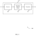
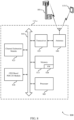
- FIG. 5 shows a block diagram 500 of a UE 115-c configured for narrowband control channel decoding in accordance with various aspects of the present disclosure.
- UE 115-c may be an example of aspects of a UE 115 described with reference to FIGs. 1-4 .
- UE 115-c may include a receiver 505, a CRS based PDCCH module 510, or a transmitter 515.
- UE 115-c may also include a processor. Each of these components may be in communication with one another.
- the receiver 505 may receive information such as packets, user data, or control information associated with various information channels (e.g., control channels, data channels, and information related to a CRS based control channel element, etc. ). Information may be passed on to the CRS based PDCCH module 510, and to other components of UE 115-c.
- the receiver 505 may receive a PDCCH based on a set of resources. In some examples, the receiver 505 may receive a message indicating a size of the broadband control region to be excluded from the set of resources.
- the receiver 505 may also receive a second PDCCH using a same precoding as the PDCCH according to a bundling configuration.
- the receiver 505 may receive a second PDCCH using a different precoding from the PDCCH according to a predetermined precoding pattern. Additionally or alternatively, the PDCCH and the second PDCCH may include the same content and may be transmitted in a different frequency resource or a different time resource. In some cases, the receiver 505 may receive a message indicating the resources of the narrowband region which include the control region for broadband communications.
- the CRS based PDCCH module 510 may establish a connection with a node (such as a UE 115 or base station 105), where the connection may include a narrowband control region, and the CRS based PDCCH module 510 may identify a set of resources in the narrowband control region based on a resource element indexing configuration associated with a CRS based demodulation scheme.
- the CRS based PDCCH module 510 may also receive a PDCCH based on the set of resources, and it may demodulate the PDCCH based at least in part on a CRS.
- the CRS based PDCCH module 510 may identify a plurality of subframes during which to monitor a DM-RS for decoding a control channel associated with a node.
- the control channel may include a narrowband region and may be within a wideband system.
- the plurality of subframes may have a same precoding for the DM-RS.
- the CRS based PDCCH module 510 may further decode the control channel based at least in part on the DM-RS.
- the transmitter 515 may transmit signals received from other components of UE 115-c. In some embodiments, the transmitter 515 may be collocated with the receiver 505 in a transceiver module.
- the transmitter 515 may include a single antenna, or it may include a plurality of antennas.
- FIG. 6 shows a block diagram 600 of a UE 115-d for narrowband control channel decoding in accordance with various aspects of the present disclosure.
- UE 115-d may be an example of aspects of a UE 115 described with reference to FIGs. 1-5 .
- UE 115-d may include a receiver 505-a, a CRS based PDCCH module 510-a, or a transmitter 515-a.
- UE 115-d may also include a processor. Each of these components may be in communication with one another.
- the CRS based PDCCH module 510-a may also include a narrowband connection module 605, a resource identification module 610, and a demodulation module 615.
- the receiver 505-a may receive information which may be passed on to CRS based PDCCH module 510-a, and to other components of UE 115-d.
- the CRS based PDCCH module 510-a may perform the operations described above with reference to FIG. 5 .
- the transmitter 515-a may transmit signals received from other components of UE 115-d.
- the narrowband connection module 605 may establish a connection with a node (such as a UE 115 or base station 105), where the connection may include a narrowband control region as described above with reference to FIGs. 2-4 . In some cases, the narrowband connection module 605 may exclude resources of the narrowband region which include a control region for broadband communications from the control channel.
- a node such as a UE 115 or base station 105
- the narrowband connection module 605 may exclude resources of the narrowband region which include a control region for broadband communications from the control channel.
- the resource identification module 610 may identify a set of resources in the narrowband control region based at least in part on a resource element indexing configuration associated with a CRS based demodulation scheme as described above with reference to FIGs. 2-4 .
- the resource element indexing configuration excludes a set of resource elements associated with a CRS configuration.
- the resource element indexing configuration excludes a set of resource elements associated with a DM-RS configuration.
- the resource element indexing configuration includes a set of separately indexed resource elements associated with a DM-RS configuration.
- the CRS demodulation scheme may, for instance, be based on a CRS configuration that includes a maximum number of CRS ports.
- the resource identification module 610 identifies a plurality of subframes during which to monitor a DM-RS for decoding a control channel associated with a node.
- the control channel may include a narrowband region of a wideband system and the plurality of subframes may have a same precoding for the DM-RS.
- the resource identification module 610 may identify two or more RBs that have the same precoding within the narrowband region.
- the resource identification module 610 may determine the resources of the narrowband region which include the control region for the broadband communications based at least in part on a message.
- the resource identification module 610 may exclude resources of the narrowband region which include a control region for broadband communications from the control channel.
- the demodulation module 615 may demodulate the PDCCH based on a CRS as described above with reference to FIGs. 2-4 . In some cases, the demodulation may also be based on a DM-RS. The demodulation module 615 may decode the control channel based at least in part on the DM-RS.
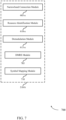
- FIG. 7 shows a block diagram 700 of a CRS based PDCCH module 510-b for narrowband control channel decoding in accordance with various aspects of the present disclosure.
- the CRS based PDCCH module 510-b may be an example of aspects of a CRS based PDCCH module 510 described with reference to FIGs. 5 or6.
- the CRS based PDCCH module 510-b may include a narrowband connection module 605-a, a resource identification module 610-a, and a demodulation module 615-a. Each of these modules may perform the functions described above with reference to FIG. 6 .
- the CRS based PDCCH module 510-b may also include a DM-RS module 705, and a symbol mapping module 710.
- the DM-RS module 705 may be configured such that the demodulation of the PDCCH may be based on a DM-RS as described above with reference to FIGs. 2-4 . In some cases the DM-RS module 705 may decode the control channel based at least in part on the DM-RS.
- the symbol mapping module 710 may map a set of modulation symbols to the set of resources, where the mapping excludes a broadband control region from the set as described above with reference to FIGs. 2-4 .
- the components of UE 115-c, UE 115-d, or CRS based PDCCH module 510-b may, individually or collectively, be implemented with at least one application specific integrated circuit (ASIC) adapted to perform some or all of the applicable functions in hardware.
- ASIC application specific integrated circuit
- the functions may be performed by one or more other processing units (or cores), on at least one IC.
- other types of integrated circuits may be used (e.g ., Structured/Platform ASICs, a field programmable gate array (FPGA), or another semi-custom IC), which may be programmed in any manner known in the art.
- the functions of each unit may also be implemented, in whole or in part, with instructions embodied in a memory, formatted to be executed by one or more general or application-specific processors.
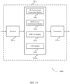
- FIG. 8 shows a diagram of a system 800 including a UE 115 configured for narrowband control channel decoding in accordance with various aspects of the present disclosure.
- System 800 may include UE 115-e, which may be an example of a UE 115 described above with reference to FIGs. 1-7 .
- UE 115-e may include a CRS based PDCCH module 810, which may be an example of a CRS based PDCCH module 510 described with reference to FIGs. 5-7 .
- UE 115-e may also include a channel estimation module 825.
- UE 115-e may also include components for bi-directional voice and data communications including components for transmitting communications and components for receiving communications. For example, UE 115-e may communicate bi-directionally with UE 115-f or base station 105-c.
- UE 115-e may also include a processor module 805, and memory 815 (including software (SW) 820), a transceiver module 835, and one or more antenna(s) 840, each of which may communicate, directly or indirectly, with one another (e.g., via buses 845).
- the transceiver module 835 may communicate bi-directionally, via the antenna(s) 840 or wired or wireless links, with one or more networks, as described above.
- the transceiver module 835 may communicate bi-directionally with a base station 105 or another UE 115.
- the transceiver module 835 may include a modem to modulate the packets and provide the modulated packets to the antenna(s) 840 for transmission, and to demodulate packets received from the antenna(s) 840. While UE 115-e may include a single antenna 840, UE 115-e may also have multiple antennas 840 capable of concurrently transmitting or receiving multiple wireless transmissions.
- the channel estimation module 825 may estimate channel conditions and generate channel state information (CSI) reports based on the channel estimates.
- CRS may be used for channel estimation.
- a wireless communications link may then be updated based on the CSI.
- the memory 815 may include random access memory (RAM) and read only memory (ROM).
- the memory 815 may store computer-readable, computer-executable software/firmware code 820 including instructions that, when executed, cause the processor module 805 to perform various functions described herein (e.g ., narrowband control channel decoding, etc.).
- the software/firmware code 820 may not be directly executable by the processor module 805 but cause a computer ( e.g ., when compiled and executed) to perform functions described herein.
- the processor module 805 may include an intelligent hardware device, (e.g. , a central processing unit (CPU), a microcontroller, an ASIC, etc.)
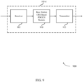
- FIG. 9 shows a block diagram 900 of a base station 105-d configured for narrowband control channel decoding in accordance with various aspects of the present disclosure.
- Base station 105-d may be an example of aspects of a base station 105 or a UE 115 described with reference to FIGs. 1-8 .
- Base station 105-d may include a receiver 905, a base station CRS based PDCCH module 910, or a transmitter 915.
- Base station 105-d may also include a processor. Each of these components may be in communication with one another.
- the structure of base station 105-d may be found in a UE 115 by operating according to D2D operations.
- the receiver 905 may receive information such as packets, user data, or control information associated with various information channels (e.g ., control channels, data channels, and information related to a CRS based control channel element, etc.). Information may be passed on to the base station CRS based PDCCH module 910, and to other components of base station 105-d.
- information channels e.g ., control channels, data channels, and information related to a CRS based control channel element, etc.
- Information may be passed on to the base station CRS based PDCCH module 910, and to other components of base station 105-d.
- the base station CRS based PDCCH module 910 may establish a connection with a UE 115, where the connection may include a narrowband control region, identify a set of resources for the UE 115 in the narrowband control region based at least in part on a resource element indexing configuration associated with a CRS based demodulation scheme, transmit a PDCCH to the UE 115using the set of resources, and transmit a CRS in a same resource block as the set of resources.
- the transmitter 915 may transmit signals received from other components of base station 105-d. In some embodiments, the transmitter 915 may be collocated with the receiver 905 in a transceiver module. The transmitter 915 may include a single antenna, or it may include a plurality of antennas. In some examples, the transmitter 515 may transmit a message indicating a size of the broadband control region to be excluded. In some examples, the transmitter 515 may transmit a second PDCCH using a same precoding as the PDCCH according to PDCCH bundling configuration. In some examples, the transmitter 515 may transmit a second PDCCH using a different precoding from the PDCCH according to a predetermined precoding pattern. The PDCCH and the second PDCCH may include the same content and may be transmitted in a different frequency resource or a different time resource.
- FIG. 10 shows a block diagram 1000 of a base station 105-e for narrowband control channel decoding in accordance with various aspects of the present disclosure.
- Base station 105-e may be an example of aspects of a base station 105 described with reference to FIGs. 1-9 .
- Base station 105-e may include a receiver 905-a, a base station CRS based PDCCH module 910-a, or a transmitter 915-a.
- Base station 105-e may also include a processor. Each of these components may be in communication with one another.
- the base station CRS based PDCCH module 910-a may also include a BS narrowband connection module 1005, a BS resource identification module 1010, a PDCCH module 1015, and a CRS module 1020.
- the structure of base station 105-e may be found in a UE 115 by operating according to D2D operations.
- the receiver 905-a may receive information which may be passed on to base station CRS based PDCCH module 910-a, and to other components of base station 105-e.
- the base station CRS based PDCCH module 910-a may perform the operations described above with reference to FIG. 9 .
- the transmitter 915-a may transmit signals received from other components of base station 105-e.
- the BS narrowband connection module 1005 may establish a connection with a UE 115, where the connection may include a narrowband control region as described above with reference to FIGs. 2-4 .
- the BS resource identification module 1010 may identify a set of resources for the UE 115 in the narrowband control region based at least in part on a resource element indexing configuration associated with a CRS based demodulation scheme as described above with reference to FIGs. 2-4 .
- the PDCCH module 1015 may transmit a PDCCH to the UE 115 using the set of resources as described above with reference to FIGs. 2-4 .
- the CRS module 1020 may transmit a CRS in a same resource block as the set of resources as described above with reference to FIGs. 2-4 .
- the CRS demodulation scheme may be based on a CRS configuration comprising a maximum number of CRS ports.
- FIG. 11 shows a block diagram 1100 of a base station CRS based PDCCH module 910-b for narrowband control channel decoding in accordance with various aspects of the present disclosure.
- the base station CRS based PDCCH module 910-b may be an example of aspects of a base station CRS based PDCCH module 910 described with reference to FIGs. 9-10 .
- the base station CRS based PDCCH module 910-b may include a BS narrowband connection module 1005-a, a BS resource identification module 1010-a, a PDCCH module 1015-a, and a CRS module 1020-a. Each of these modules may perform the functions described above with reference to FIG. 10 .
- the base station CRS based PDCCH module 910-b may also include and a BS symbol mapping module 1105.
- the BS symbol mapping module 1105 may map a set of modulation symbols to the set of resources, where the mapping excludes a broadband control region from the set as described above with reference to FIGs. 2-4 .
- base station 105-d, base station 105-e, or base station CRS based PDCCH module 910-b may, individually or collectively, be implemented with at least one ASIC adapted to perform some or all of the applicable functions in hardware.
- the functions may be performed by one or more other processing units (or cores), on at least one IC.
- other types of integrated circuits may be used (e.g ., Structured/Platform ASICs, an FPGA, or another semi-custom IC), which may be programmed in any manner known in the art.
- the functions of each unit may also be implemented, in whole or in part, with instructions embodied in a memory, formatted to be executed by one or more general or application-specific processors.
- FIG. 12 shows a diagram of a system 1200 including a base station 105 configured for narrowband control channel decoding in accordance with various aspects of the present disclosure.
- System 1200 may include base station 105-f, which may be an example of a base station 105 described above with reference to FIGs. 1-11 .
- Base station 105-f may include a base station CRS based PDCCH module 1210, which may be an example of a base station CRS based PDCCH module 910 described with reference to FIGs. 9-11 .
- Base station 105-f may also include components for bi-directional voice and data communications including components for transmitting communications and components for receiving communications. For example, base station 105-f may communicate bi-directionally with base station 105-g or base station 105-h.
- base station 105-f may have one or more wired backhaul links.
- Base station 105-f may have a wired backhaul link (e.g., S1 interface, etc.) to the core network 130.
- Base station 105-f may also communicate with other base stations 105, such as base station 105-g and base station 105-h via inter-base station backhaul links ( e.g. , an X2 interface).
- Each of the base stations 105 may communicate with UEs 115 using the same or different wireless communications technologies.
- base station 105-f may communicate with other base stations such as 105-g or 105-h utilizing base station communication module 1225.
- base station communication module 1225 may provide an X2 interface within an LTE/LTE-A wireless communication network technology to provide communication between some of the base stations 105.
- base station 105-f may communicate with other base stations through core network 130.
- base station 105-f may communicate with the core network 130 through network communications module 1230.
- Base station 105-f may include a processor module 1205, memory 1215 (including software (SW) 1220), transceiver modules 1235, and antenna(s) 1240, which each may be in communication, directly or indirectly, with one another ( e.g. , over bus system 1245).
- the transceiver modules 1235 may be configured to communicate bi-directionally, via the antenna(s) 1240, with the UEs 115, which may be multi-mode devices.
- the transceiver module 1235 (or other components of the base station 105-f) may also be configured to communicate bi-directionally, via the antennas 1240, with one or more other base stations (not shown).
- the transceiver module 1235 may include a modem configured to modulate the packets and provide the modulated packets to the antennas 1240 for transmission, and to demodulate packets received from the antennas 1240.
- the base station 105-f may include multiple transceiver modules 1235, each with one or more associated antennas 1240.
- the transceiver module may be an example of a combined receiver 905 and transmitter 915 of FIG. 9 .
- the memory 1215 may include RAM and ROM.
- the memory 1215 may also store computer-readable, computer-executable software code 1220 containing instructions that are configured to, when executed, cause the processor module 1210 to perform various functions described herein (e.g ., a CRS based control channel element, selecting coverage enhancement techniques, call processing, database management, message routing, etc. ).
- the software 1220 may not be directly executable by the processor module 1205 but be configured to cause the computer, ( e.g. , when compiled and executed), to perform functions described herein.
- the processor module 1205 may include an intelligent hardware device, ( e.g., a CPU, a microcontroller, an ASIC, etc.).
- the processor module 1205 may include various special purpose processors such as encoders, queue processing modules, base band processors, radio head controllers, digital signal processor (DSPs), and the like.
- the base station communications module 1225 may manage communications with other base stations 105.
- the communications management module may include a controller or scheduler for controlling communications with UEs 115 in cooperation with other base stations 105.
- the base station communications module 1225 may coordinate scheduling for transmissions to UEs 115 for various interference mitigation techniques such as beamforming or joint transmission.
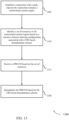
- FIG. 13 shows a flowchart illustrating a method 1300 for narrowband control channel decoding in accordance with various aspects of the present disclosure.
- the operations of method 1300 may be implemented by a UE 115 or its components as described with reference to FIGs. 1-12 .
- the operations of method 1300 may be performed by the CRS based PDCCH module 510 as described with reference to FIGs. 5-8 .
- a UE 115 may execute a set of codes to control the functional elements of the UE 115 to perform the functions described below. Additionally or alternatively, the UE 115 may perform aspects the functions described below using special-purpose hardware.
- the UE 115 may establish a connection with a node (such as a UE 115 or base station 105), where the connection may include a narrowband control region as described above with reference to FIGs. 2-4 .
- the operations of block 1305 may be performed by the narrowband connection module 605 as described above with reference to FIG. 6 .
- the UE 115 may identify a set of resources in the narrowband control region based at least in part on a resource element indexing configuration associated with a CRS based demodulation scheme as described above with reference to FIGs. 2-4 .
- the operations of block 1310 may be performed by the resource identification module 610 as described above with reference to FIG. 6 .
- the UE 115 may receive a PDCCH based on the set of resources as described above with reference to FIGs. 2-4 .
- the operations of block 1315 may be performed by the receiver 505 as described above with reference to FIG. 5 .
- the UE 115 may demodulate the PDCCH based at least in part on a CRS as described above with reference to FIGs. 2-4 .
- the operations of block 1320 may be performed by the demodulation module 615 as described above with reference to FIG. 6 .
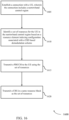
- FIG. 14 shows a flowchart illustrating a method 1400 for narrowband control channel decoding in accordance with various aspects of the present disclosure.
- the operations of method 1400 may be implemented by a UE 115 or its components as described with reference to FIGs. 1-12 .
- the operations of method 1400 may be performed by the CRS based PDCCH module 510 as described with reference to FIGs. 5-8 .
- a UE 115 may execute a set of codes to control the functional elements of the UE 115 to perform the functions described below. Additionally or alternatively, the UE 115 may perform aspects the functions described below using special-purpose hardware.
- the method 1400 may also incorporate aspects of method 1300 of FIG. 13 .
- the UE 115 may establish a connection with a node (such as a UE 115 or base station 105), where the connection may include a narrowband control region as described above with reference to FIGs. 2-4 .
- the operations of block 1405 may be performed by the narrowband connection module 605 as described above with reference to FIG. 6 .
- the UE 115 may identify a set of resources in the narrowband control region based at least in part on a resource element indexing configuration associated with a CRS based demodulation scheme as described above with reference to FIGs. 2-4 .
- the operations of block 1410 may be performed by the resource identification module 610 as described above with reference to FIG. 6 .
- the UE 115 may map a set of modulation symbols to the set of resources, where the mapping excludes a broadband control region from the set as described above with reference to FIGs. 2-4 .
- the operations of block 1415 may be performed by the symbol mapping module 710 as described above with reference to FIG. 7 .
- the UE 115 may receive a PDCCH based on the set of resources as described above with reference to FIGs. 2-4 .
- the operations of block 1420 may be performed by the receiver 505 as described above with reference to FIG. 5 .
- the UE 115 may demodulate the PDCCH based at least in part on a CRS as described above with reference to FIGs. 2-4 .
- the operations of block 1425 may be performed by the demodulation module 615 as described above with reference to FIG. 6 .
- FIG. 15 shows a flowchart illustrating a method 1500 for narrowband control channel decoding in accordance with various aspects of the present disclosure.
- the operations of method 1500 may be implemented by a UE 115 or its components as described with reference to FIGs. 1-12 .
- the operations of method 1500 may be performed by the CRS based PDCCH module 510 as described with reference to FIGs. 5-8 .
- a UE 115 may execute a set of codes to control the functional elements of the UE 115 to perform the functions described below. Additionally or alternatively, the UE 115 may perform aspects the functions described below using special-purpose hardware.
- the method 1500 may also incorporate aspects of methods 1300, and 1400 of FIGs. 13 or 14 .
- the UE 115 may establish a connection with a node (such as a UE 115 or base station 105), where the connection may include a narrowband control region as described above with reference to FIGs. 2-4 .
- the operations of block 1505 may be performed by the narrowband connection module 605 as described above with reference to FIG. 6 .
- the UE 115 may identify a set of resources in the narrowband control region based at least in part on a resource element indexing configuration associated with a CRS based demodulation scheme as described above with reference to FIGs. 2-4 .
- the operations of block 1510 may be performed by the resource identification module 610 as described above with reference to FIG. 6 .
- the UE 115 may receive a PDCCH based on the set of resources as described above with reference to FIGs. 2-4 .
- the operations of block 1515 may be performed by the receiver 505 as described above with reference to FIG. 5 .
- the UE 115 may demodulate the PDCCH based at least in part on a CRS as described above with reference to FIGs. 2-4 .
- the operations of block 1520 may be performed by the demodulation module 615 as described above with reference to FIG. 6 .
- the UE 115 may receive a second PDCCH using a same precoding as the PDCCH according to a bundling configuration or a different precoding from the PDCCH according to a predetermined precoding pattern as described above with reference to FIGs. 2-4 .
- the operations of block 1525 may be performed by the receiver 505 as described above with reference to FIG. 5 .
- FIG. 16 shows a flowchart illustrating a method 1600 for narrowband control channel decoding in accordance with various aspects of the present disclosure.
- the operations of method 1600 may be implemented by a wireless node such as a base station 105 or a UE 115 (e.g., in operating in D2D mode) or its components as described with reference to FIGs. 1-12 .
- the operations of method 1600 may be performed by the base station CRS based PDCCH module 910 as described with reference to FIGs. 9-12 .
- a base station 105 may execute a set of codes to control the functional elements of the base station 105 to perform the functions described below. Additionally or alternatively, the base station 105 may perform aspects the functions described below using special-purpose hardware.
- the wireless node may establish a connection with a UE, where the connection may include a narrowband control region as described above with reference to FIGs. 2-4 .
- the operations of block 1605 may be performed by the BS narrowband connection module 1005 as described above with reference to FIG. 1 .
- the wireless node may identify a set of resources for the UE in the narrowband control region based at least in part on a resource element indexing configuration associated with a CRS based demodulation scheme as described above with reference to FIGs. 2-4 .
- the operations of block 1610 may be performed by the BS resource identification module 1010 as described above with reference to FIG. 1 .
- the wireless node may transmit a PDCCH to the UE using the set of resources as described above with reference to FIGs. 2-4 .
- the operations of block 1615 may be performed by the PDCCH module 1015 as described above with reference to FIG. 1 .
- the wireless node may transmit a CRS in a same resource block as the set of resources as described above with reference to FIGs. 2-4 .
- the operations of block 1620 may be performed by the CRS module 1020 as described above with reference to FIG. 1 .
- FIG. 17 shows a flowchart illustrating a method 1700 for narrowband control channel decoding in accordance with various aspects of the present disclosure.
- the operations of method 1700 may be implemented by a wireless node such as a base station 105 or a UE 115 (e.g., in operating in D2D mode) or its components as described with reference to FIGs. 1-12 .
- the operations of method 1700 may be performed by the base station CRS based PDCCH module 910 as described with reference to FIGs. 9-12 .
- a base station 105 may execute a set of codes to control the functional elements of the base station 105 to perform the functions described below. Additionally or alternatively, the base station 105 may perform aspects the functions described below using special-purpose hardware.
- the method 1700 may also incorporate aspects of method1600 of FIG. 16 .
- the wireless node establishes a connection with a UE, where the connection includes a narrowband control region as described above with reference to FIGs. 2-4 .
- the operations of block 1705 may be performed by the BS narrowband connection module 1005 as described above with reference to FIG. 1 .
- the wireless node identifies a set of resources for the UE in the narrowband control region based at least in part on a resource element indexing configuration associated with a CRS based demodulation scheme as described above with reference to FIGs. 2-4 .
- the operations of block 1710 may be performed by the BS resource identification module 1010 as described above with reference to FIG. 1 .
- the wireless node maps a set of modulation symbols to the set of resources, where the mapping excludes a broadband control region from the set as described above with reference to FIGs. 2-4 .
- the operations of block 1715 may be performed by the symbol mapping module 710 as described above with reference to FIG. 7 .
- the wireless node transmits a message indicating a size of the broadband control region to be excluded as described above with reference to FIGs. 2-4 .
- the operations of block 1720 may be performed by the transmitter 915 as described above with reference to FIG. 9 .
- the wireless node transmits a PDCCH to the UE using the set of resources as described above with reference to FIGs. 2-4 .
- the operations of block 1725 may be performed by the PDCCH module 1015 as described above with reference to FIG. 1 .
- the wireless node transmits a CRS in a same resource block as the set of resources as described above with reference to FIGs. 2-4 .
- the operations of block 1730 may be performed by the CRS module 1020 as described above with reference to FIG. 1 .
- FIG. 18 shows a flowchart illustrating a method 1800 for narrowband control channel decoding in accordance with various aspects of the present disclosure.
- the operations of method 1800 may be implemented by a wireless node such as a base station 105 or a UE 115 (e.g., in operating in D2D mode) or its components as described with reference to FIGs. 1-12 .
- the operations of method 1800 may be performed by the base station CRS based PDCCH module 910 as described with reference to FIGs. 9-12 .
- a base station 105 may execute a set of codes to control the functional elements of the base station 105 to perform the functions described below. Additionally or alternatively, the base station 105 may perform aspects the functions described below using special-purpose hardware.
- the method 1800 may also incorporate aspects of methods 1600, and 1700 of FIGs. 16 or 17 .
- the wireless node may establish a connection with a UE, where the connection may include a narrowband control region as described above with reference to FIGs. 2-4 .
- the operations of block 1805 may be performed by the BS narrowband connection module 1005 as described above with reference to FIG. 1 .
- the wireless node may identify a set of resources for the UE in the narrowband control region based at least in part on a resource element indexing configuration associated with a CRS based demodulation scheme as described above with reference to FIGs. 2-4 .
- the operations of block 1810 may be performed by the BS resource identification module 1010 as described above with reference to FIG. 1 .
- the wireless node may transmit a PDCCH to the UE using the set of resources as described above with reference to FIGs. 2-4 .
- the operations of block 1815 may be performed by the PDCCH module 1015 as described above with reference to FIG. 1 .
- the wireless node may transmit a CRS in a same resource block as the set of resources as described above with reference to FIGs. 2-4 .
- the operations of block 1820 may be performed by the CRS module 1020 as described above with reference to FIG. 1 .
- the wireless node may transmit a second PDCCH using a same precoding as the PDCCH according to PDCCH bundling configuration or a different precoding from the PDCCH according to a predetermined precoding pattern as described above with reference to FIGs. 2-4 .
- the operations of block 1825 may be performed by the transmitter 915 as described above with reference to FIG. 9 .
- FIG. 19 shows a flowchart illustrating a method 1900 for narrowband control channel decoding in accordance with various aspects of the present disclosure.
- the operations of method 1900 may be implemented by a wireless node such as a base station 105 or a UE 115 or its components as described with reference to FIGs. 1-12 .
- the operations of method 1900 may be performed by the CRS based PDCCH module 510 as described with reference to FIGs. 5-8 .
- a UE 115 may execute a set of codes to control the functional elements of the UE 115 to perform the functions described below. Additionally or alternatively, the UE 115 may perform aspects of the functions described below using special-purpose hardware.
- the UE 115 may identify a set of subframes during which to monitor a demodulation reference signal (DM-RS) for decoding a control channel associated with a node, where the control channel comprises a narrowband region of a wideband system, and where the set of subframes have a same precoding for the DM-RS as described above with reference to FIGs. 2-4 .
- the operations of block 1905 may be performed by the resource identification module 610 as described with reference to FIGs. 6 and 7 .
- the UE 115 may decode the control channel based on the DM-RS as described above with reference to FIGs. 2-4 .
- the operations of block 1910 may be performed by the demodulation module 615 as described with reference to FIGs. 6-7 , or the DM-RS module 705 as described with reference to FIG. 7 .
- FIG. 20 shows a flowchart illustrating a method 2000 for narrowband control channel decoding in accordance with various aspects of the present disclosure.
- the operations of method 2000 may be implemented by a UE 115 or its components as described with reference to FIGs. 1-12 .
- the operations of method 2000 may be performed by the CRS based PDCCH module 510 as described with reference to FIGs. 5-8 .
- the UE 115 may execute a set of codes to control the functional elements of the UE 115 to perform the functions described below. Additionally or alternatively, the UE 115 may perform aspects of the functions described below using special-purpose hardware.
- the UE 115 may identify a set of subframes during which to monitor a demodulation reference signal (DM-RS) for decoding a control channel associated with a node, where the control channel comprises a narrowband region of a wideband system, and where the set of subframes have a same precoding for the DM-RS as described above with reference to FIGs. 2-4 .
- the operations of block 2005 may be performed by the resource identification module 610 as described with reference to FIGs. 6 and 7 .
- the UE 115 may decode the control channel based on the DM-RS as described above with reference to FIGs. 2-4 .
- the operations of block 2010 may be performed by the demodulation module 615 as described with reference to FIGs. 6-7 , or the DM-RS module 705 as described with reference to FIG. 7 .
- the UE 115 may identify two or more resource blocks (RBs) that have the same precoding within the narrowband region as described above with reference to FIGs. 2-4 .
- the operations of block 2015 may be performed by the resource identification module 610 as described with reference to FIGs. 6 and 7 .
- FIG. 21 shows a flowchart illustrating a method 2100 for narrowband control channel decoding in accordance with various aspects of the present disclosure.
- the operations of method 2100 may be implemented by a UE 115 or its components as described with reference to FIGs. 1-12 .
- the operations of method 2100 may be performed by the CRS based PDCCH module 510 as described with reference to FIGs. 5-8 .
- the UE 115 may execute a set of codes to control the functional elements of the UE 115 to perform the functions described below. Additionally or alternatively, the UE 115 may perform aspects of the functions described below using special-purpose hardware.
- the UE 115 may identify a set of subframes during which to monitor a demodulation reference signal (DM-RS) for decoding a control channel associated with a node, where the control channel comprises a narrowband region of a wideband system, and where the set of subframes have a same precoding for the DM-RS as described above with reference to FIGs. 2-4 .
- the operations of block 2105 may be performed by the resource identification module 610 as described with reference to FIGs. 6 and 7 .
- the UE 115 may decode the control channel based on the DM-RS as described above with reference to FIGs. 2-4 .
- the operations of block 2110 may be performed by the demodulation module 615 as described with reference to FIGs. 6-7 , or the DM-RS module 705 as described with reference to FIG. 7 .
- the UE 115 may exclude resources of the narrowband region that comprise a control region for broadband communications from the control channel as described above with reference to FIGs. 2-4 .
- the operations of block 2115 may be performed by the narrowband connection module 605 or the resource identification module 610 as described with reference to FIGs. 6-7 .
- methods 1300, 1400, 1500, 1600, 1700, 1800, 1900, 2000, and 2100 may provide for narrowband control channel decoding. It should be noted that methods 1300, 1400, 1500, 1600, 1700, 1800, 1900, 2000, and 2100 describe possible implementation, and that the operations and the steps may be rearranged or otherwise modified such that other implementations are possible. In some examples, aspects from two or more of the methods 1300, 1400, 1500, 1600, 1700, 1800, 1900, 2000, and 2100 may be combined.
- Information and signals may be represented using any of a variety of different technologies and techniques.
- data, instructions, commands, information, signals, bits, symbols, and chips that may be referenced throughout the above description may be represented by voltages, currents, electromagnetic waves, magnetic fields or particles, optical fields or particles, or any combination thereof.
- a general-purpose processor may be a microprocessor, but in the alternative, the processor may be any conventional processor, controller, microcontroller, or state machine.
- a processor may also be implemented as a combination of computing devices (e.g., a combination of a DSP and a microprocessor, multiple microprocessors, one or more microprocessors in conjunction with a DSP core, or any other such configuration).
- the functions described herein may be implemented in hardware, software executed by a processor, firmware, or any combination thereof. If implemented in software executed by a processor, the functions may be stored on or transmitted over as one or more instructions or code on a computer-readable medium. Other examples and implementations are within the scope of the appended claims. For example, due to the nature of software, functions described above can be implemented using software executed by a processor, hardware, firmware, hardwiring, or combinations of any of these. Features implementing functions may also be physically located at various positions, including being distributed such that portions of functions are implemented at different physical locations.
- Computer-readable media includes both non-transitory computer storage media and communication media including any medium that facilitates transfer of a computer program from one place to another.
- a non-transitory storage medium may be any available medium that can be accessed by a general purpose or special purpose computer.
- non-transitory computer-readable media can comprise RAM, ROM, electrically erasable programmable read only memory (EEPROM), compact disk (CD) ROM or other optical disk storage, magnetic disk storage or other magnetic storage devices, or any other non-transitory medium that can be used to carry or store desired program code means in the form of instructions or data structures and that can be accessed by a general-purpose or special-purpose computer, or a general-purpose or special-purpose processor.
- RAM random access memory
- ROM read only memory
- EEPROM electrically erasable programmable read only memory
- CD compact disk
- magnetic disk storage or other magnetic storage devices or any other non-transitory medium that can be used to carry or store desired program code means in the form of instructions or data structures
- any connection is properly termed a computer-readable medium.
- the software is transmitted from a website, server, or other remote source using a coaxial cable, fiber optic cable, twisted pair, digital subscriber line (DSL), or wireless technologies such as infrared, radio, and microwave
- the coaxial cable, fiber optic cable, twisted pair, DSL, or wireless technologies such as infrared, radio, and microwave are included in the definition of medium.
- Disk and disc include CD, laser disc, optical disc, digital versatile disc (DVD), floppy disk and Blu-ray disc where disks usually reproduce data magnetically, while discs reproduce data optically with lasers. Combinations of the above are also included within the scope of computer-readable media.
- CDMA code division multiple access
- TDMA time division multiple access
- FDMA frequency division multiple access
- SC-FDMA SC-FDMA
- a CDMA system may implement a radio technology such as CDMA2000, Universal Terrestrial Radio Access (UTRA), etc.
- CDMA2000 covers IS-2000, IS-95, and IS-856 standards.
- IS-2000 Releases 0 and A are commonly referred to as CDMA2000 1X, 1X, etc.
- IS-856 (TIA-856) is commonly referred to as CDMA2000 1xEV-DO, High Rate Packet Data (HRPD), etc.
- UTRA includes Wideband CDMA (WCDMA) and other variants of CDMA.
- a TDMA system may implement a radio technology such as Global System for Mobile Communications (GSM).
- GSM Global System for Mobile Communications
- An OFDMA system may implement a radio technology such as Ultra Mobile Broadband (UMB), Evolved UTRA (E-UTRA), IEEE 802.11 (Wi-Fi), IEEE 802.16 (WiMAX), IEEE 802.20, Flash-OFDM, etc.
- UMB Ultra Mobile Broadband
- E-UTRA Evolved UTRA
- Wi-Fi Wi-Fi
- WiMAX IEEE 802.16
- IEEE 802.20 Flash-OFDM
- UTRA and E-UTRA are part of Universal Mobile Telecommunications system (UMTS).
- 3GPP Long Term Evolution (LTE) and LTE-Advanced (LTE-A) are new releases of Universal Mobile Telecommunications System (UMTS) that use E-UTRA.
- UTRA, E-UTRA, UMTS, LTE, LTE-A, and Global System for Mobile communications are described in documents from an organization named "3rd Generation Partnership Project” (3GPP).
- CDMA2000 and UMB are described in documents from an organization named “3rd Generation Partnership Project 2" (3GPP2).
- the techniques described herein may be used for the systems and radio technologies mentioned above as well as other systems and radio technologies.
Landscapes
- Engineering & Computer Science (AREA)
- Signal Processing (AREA)
- Computer Networks & Wireless Communication (AREA)
- Mobile Radio Communication Systems (AREA)
Claims (15)
- Un procédé de communication sans fil au niveau d'un noeud sans fil (115 ; 115-a ; 115-b ; 115-c ; 115-d ; 115-e ; 115-f ; 155-g ; 115-h ; 105 ; 105-a ; 105-b ; 105-c ; 105-d ; 105-e ; 105-f ; 105-g ; 105-h), comprenant :l'identification (1710) d'un ensemble de ressources pour un équipement utilisateur, UE, (115 ; 115-a ; 115-b ; 115-c ; 115-d ; 115-e ; 115-f ; 155-g ; 115-h) dans une région de contrôle à bande étroite, au moins en partie sur la base d'une configuration d'indexage d'élément de ressource associée à un schéma de démodulation basé sur un signal de référence spécifique à la cellule, CRS ;le mappage (1715) d'un ensemble de symboles de modulation vers l'ensemble de ressources, dans lequel le mappage exclut de l'ensemble une région de contrôle à large bande ;la transmission (1720) d'un message indiquant une taille de la région de contrôle à large bande à exclure ;la transmission (1725) d'un canal de contrôle à l'UE (115 ; 115-a ; 115-b ; 115-c ; 115-d ; 115-e ; 115-f ; 155-g ; 115-h) en utilisant l'ensemble de ressources ; etla transmission (1730) d'un CRS dans un même bloc de ressources que l'ensemble de ressources.
- Le procédé selon la revendication 1, comprenant en outre l'établissement (1705) d'une connexion avec l'UE (115 ; 115-a ; 115-b ; 115-c ; 115-d ; 115-e ; 115-f ; 155-g ; 115-h), dans lequel la connexion comporte la région de contrôle à bande étroite.
- Le procédé selon une des revendications précédentes, dans lequel le canal de contrôle est un canal physique de contrôle de liaison descendante, PDCCH.
- Le procédé selon une des revendications précédentes, dans lequel le canal de contrôle comprend un élément de canal de contrôle, CCE, qui comprend un ensemble de groupes d'éléments de ressource, REG.
- Le procédé selon la revendication 4, dans lequel chaque REG de l'ensemble de REG est distribué en temps et fréquence pendant la pluralité de sous-trames à l'intérieur de la région de contrôle à bande étroite.
- Le procédé selon la revendication 4, dans lequel chaque REG de l'ensemble de REG exclut des éléments de ressource qui comprennent un signal de référence de démodulation, DM-RS.
- Le procédé selon la revendication 1, dans lequel un seul précodeur est appliqué pour chaque paire de blocs de ressources physiques du canal de contrôle.
- Un noeud sans fil (115 ; 115-a ; 115-b ; 115-c ; 115-d ; 115-e ; 115-f ; 155-g ; 115-h ; 105 ; 105-a ; 105-b ; 105-c ; 105-d ; 105-e ; 105-f ; 105-g ; 105-h) comprenant :un moyen pour identifier un ensemble de ressources pour un équipement utilisateur (115 ; 115-a ; 115-b ; 115-c ; 115-d ; 115-e ; 115-f ; 155-g ; 115-h) dans une région de contrôle à bande étroite, au moins en partie sur la base d'une configuration d'indexage d'élément de ressource associée à un schéma de démodulation basé sur un signal de référence spécifique à la cellule (CRS) ;un moyen pour mapper un ensemble de symboles de modulation vers l'ensemble de ressources, dans lequel le mappage exclut de l'ensemble une région de contrôle à large bande ;un moyen pour transmettre un message indiquant une taille de la région de contrôle à large bande à exclure ;un moyen pour transmettre un canal de contrôle à l'UE (115 ; 115-a ; 115-b ; 115-c ; 115-d ; 115-e ; 115-f ; 155-g ; 115-h) en utilisant l'ensemble de ressources ; etun moyen pour transmettre un CRS dans un même bloc de ressources que l'ensemble de ressources.
- Le noeud sans fil (115 ; 115-a ; 115-b ; 115-c ; 115-d ; 115-e ; 115-f ; 155-g ; 115-h ; 105 ; 105-a ; 105-b ; 105-c ; 105-d ; 105-e ; 105-f ; 105-g ; 105-h) selon la revendication 8, comprenant en outre un moyen pour établir une connexion avec l'UE (115 ; 115-a ; 115-b ; 115-c ; 115-d ; 115-e ; 115-f ; 155-g ; 115-h), dans lequel la connexion comporte la région de contrôle à bande étroite.
- Le noeud sans fil (115 ; 115-a ; 115-b ; 115-c ; 115-d ; 115-e ; 115-f ; 155-g ; 115-h ; 105 ; 105-a ; 105-b ; 105-c ; 105-d ; 105-e ; 105-f ; 105-g ; 105-h) selon une des revendications 8 à 9, dans lequel le canal de contrôle est un canal physique de contrôle de liaison descendante, PDCCH.
- Le noeud sans fil (115 ; 115-a ; 115-b ; 115-c ; 115-d ; 115-e ; 115-f ; 155-g ; 115-h ; 105 ; 105-a ; 105-b ; 105-c ; 105-d ; 105-e ; 105-f ; 105-g ; 105-h) selon une des revendications 8 à 10, dans lequel le canal de contrôle comprend un élément de canal de contrôle, CCE, qui comprend un ensemble de groupes d'éléments de ressource, REG.
- Le noeud sans fil (115 ; 115-a ; 115-b ; 115-c ; 115-d ; 115-e ; 115-f ; 155-g ; 115-h ; 105 ; 105-a ; 105-b ; 105-c ; 105-d ; 105-e ; 105-f ; 105-g ; 105-h) selon la revendication 11, dans lequel chaque REG de l'ensemble de REG est distribué en temps et fréquence pendant la pluralité de sous-trames à l'intérieur de la région de contrôle à bande étroite.
- Le noeud sans fil (115 ; 115-a ; 115-b ; 115-c ; 115-d ; 115-e ; 115-f ; 155-g ; 115-h ; 105 ; 105-a ; 105-b ; 105-c ; 105-d ; 105-e ; 105-f ; 105-g ; 105-h) selon la revendication 11, dans lequel chaque REG de l'ensemble de REG exclut des éléments de ressource qui comprennent un signal de référence de démodulation, DM-RS.
- Le noeud sans fil (115 ; 115-a ; 115-b ; 115-c ; 115-d ; 115-e ; 115-f ; 155-g ; 115-h ; 105 ; 105-a ; 105-b ; 105-c ; 105-d ; 105-e ; 105-f ; 105-g ; 105-h) selon la revendication 8, dans lequel un seul précodeur est appliqué pour chaque paire de blocs de ressources physiques du canal de contrôle.
- Un programme de calculateur comprenant des instructions qui, lorsque le programme est exécuté par un calculateur, amènent le calculateur à réaliser le procédé selon une des revendications 1 à 7.
Applications Claiming Priority (5)
| Application Number | Priority Date | Filing Date | Title |
|---|---|---|---|
| US201462073923P | 2014-10-31 | 2014-10-31 | |
| US201462074535P | 2014-11-03 | 2014-11-03 | |
| US14/927,210 US10560235B2 (en) | 2014-10-31 | 2015-10-29 | Narrowband control channel decoding |
| EP15795078.3A EP3213452B1 (fr) | 2014-10-31 | 2015-10-30 | Décodage de canal de commande à bande étroite |
| PCT/US2015/058271 WO2016070018A1 (fr) | 2014-10-31 | 2015-10-30 | Décodage de canal de commande à bande étroite |
Related Parent Applications (1)
| Application Number | Title | Priority Date | Filing Date |
|---|---|---|---|
| EP15795078.3A Division EP3213452B1 (fr) | 2014-10-31 | 2015-10-30 | Décodage de canal de commande à bande étroite |
Publications (3)
| Publication Number | Publication Date |
|---|---|
| EP3809624A1 EP3809624A1 (fr) | 2021-04-21 |
| EP3809624C0 EP3809624C0 (fr) | 2023-07-26 |
| EP3809624B1 true EP3809624B1 (fr) | 2023-07-26 |
Family
ID=55853870
Family Applications (2)
| Application Number | Title | Priority Date | Filing Date |
|---|---|---|---|
| EP20214731.0A Active EP3809624B1 (fr) | 2014-10-31 | 2015-10-30 | Décodage de canal de commande à bande étroite |
| EP15795078.3A Active EP3213452B1 (fr) | 2014-10-31 | 2015-10-30 | Décodage de canal de commande à bande étroite |
Family Applications After (1)
| Application Number | Title | Priority Date | Filing Date |
|---|---|---|---|
| EP15795078.3A Active EP3213452B1 (fr) | 2014-10-31 | 2015-10-30 | Décodage de canal de commande à bande étroite |
Country Status (5)
| Country | Link |
|---|---|
| US (1) | US10560235B2 (fr) |
| EP (2) | EP3809624B1 (fr) |
| JP (1) | JP6644779B2 (fr) |
| CN (2) | CN107078884B (fr) |
| WO (1) | WO2016070018A1 (fr) |
Families Citing this family (29)
| Publication number | Priority date | Publication date | Assignee | Title |
|---|---|---|---|---|
| US10791542B2 (en) | 2012-01-27 | 2020-09-29 | Qualcomm Incorporated | Regional and narrow band common reference signal (CRS) for user equipment (UE) relays |
| JP6325693B2 (ja) * | 2015-01-29 | 2018-05-16 | 株式会社Nttドコモ | ユーザ端末、無線基地局及び無線通信方法 |
| WO2016204590A1 (fr) * | 2015-06-18 | 2016-12-22 | 엘지전자 주식회사 | Procédé pour régler un signal de référence pour une communication v2v dans un système de communication sans fil et dispositif associé |
| CN108353381B (zh) | 2015-11-04 | 2022-01-04 | 交互数字专利控股公司 | 用于带宽缩减的wtru的寻呼过程的方法 |
| EP3371910A1 (fr) | 2015-11-04 | 2018-09-12 | Interdigital Patent Holdings, Inc. | Procédés et procédures de fonctionnement de lte à bande étroite |
| EP3372017B1 (fr) * | 2015-11-06 | 2020-05-06 | Sony Corporation | Dispositif de communication, équipement d'infrastructure, systèmes et procédés de communication |
| EP3378257B1 (fr) * | 2015-11-17 | 2020-04-22 | Telefonaktiebolaget LM Ericsson (PUBL) | Procédé, dispositif de communication sans fil et noeud radio pour l'attribution de puissance en liaison descendante lors du déploiement d'un système à bande étroite dans un système à large bande |
| US10104651B2 (en) * | 2015-12-17 | 2018-10-16 | Mediatek Inc. | Physical downlink control channel design for narrow band internet of things |
| WO2017183926A1 (fr) | 2016-04-20 | 2017-10-26 | Lg Electronics Inc. | Procédé destiné à la connexion à une station de base avec une largeur de bande flexible |
| US11277223B2 (en) * | 2016-05-20 | 2022-03-15 | Apple Inc. | Control channel design for category-A devices |
| US10517021B2 (en) | 2016-06-30 | 2019-12-24 | Evolve Cellular Inc. | Long term evolution-primary WiFi (LTE-PW) |
| CN107733626B (zh) * | 2016-08-12 | 2021-02-19 | 株式会社Kt | 用于针对bl/ce用户终端发送或接收多播控制信道的方法和装置 |
| US10404340B2 (en) * | 2016-10-11 | 2019-09-03 | Qualcomm Incorporated | Dynamic adjustment of transmission properties with continuous precoding |
| TWI647965B (zh) * | 2016-12-15 | 2019-01-11 | 聯發科技股份有限公司 | 窄帶實體下行鏈路控制通道的解碼方法及設備 |
| US10575361B2 (en) * | 2017-01-31 | 2020-02-25 | Apple Inc. | Fast switching between control channels during radio resource control connection |
| JP2020109880A (ja) * | 2017-04-25 | 2020-07-16 | シャープ株式会社 | 端末装置、基地局装置、通信方法、および、集積回路 |
| JP2020520147A (ja) | 2017-05-03 | 2020-07-02 | アイディーエーシー ホールディングス インコーポレイテッド | アップリンク制御情報を送信するための方法、システム、および装置 |
| US10560237B2 (en) * | 2017-05-30 | 2020-02-11 | Qualcomm Incorporated | Cell-specific reference signal transmissions for evolved machine type communication |
| EP3499971B1 (fr) * | 2017-09-15 | 2020-09-02 | Guangdong Oppo Mobile Telecommunications Corp., Ltd. | Procédé de transmission de données, dispositif de réseau, et dispositif terminal |
| US10715210B1 (en) * | 2017-11-17 | 2020-07-14 | Qualcomm Incorporated | Synchronization signal repetition pattern for a discovery reference signal in narrowband communications |
| CN109951264B (zh) * | 2017-12-20 | 2022-06-24 | 上海诺基亚贝尔股份有限公司 | 用于通信的方法、设备以及计算机可读介质 |
| US10356752B1 (en) * | 2018-07-02 | 2019-07-16 | Qualcomm Incorporated | Early termination for paging search in common search space |
| EP3824687A4 (fr) | 2018-07-20 | 2022-03-09 | Lenovo (Beijing) Limited | Procédé et appareil d'amélioration de performances de mpdcch |
| WO2020032736A1 (fr) | 2018-08-09 | 2020-02-13 | 엘지전자 주식회사 | Procédé pour améliorer les performances d'émission et de réception d'un canal de commande de liaison descendante de type lte mtc et appareil associé |
| CN111371480B (zh) * | 2018-12-25 | 2023-04-14 | 中兴通讯股份有限公司 | 数据的预编码处理方法及装置、存储介质 |
| WO2020147726A1 (fr) | 2019-01-14 | 2020-07-23 | Telefonaktiebolaget Lm Ericsson (Publ) | Procédé et appareil d'estimation de retard de multiples trajets |
| CN113906703A (zh) * | 2019-05-31 | 2022-01-07 | 高通股份有限公司 | 用于物理下行链路控制信道的窄带解调参考信号捆绑 |
| US11323236B2 (en) | 2019-06-25 | 2022-05-03 | Qualcomm Incorporated | Narrowband PDCCH DMRS bundling with enhanced coverage |
| US11463208B2 (en) | 2019-08-09 | 2022-10-04 | Qualcomm Incorporated | Enhancements for multi-TRP modes |
Family Cites Families (20)
| Publication number | Priority date | Publication date | Assignee | Title |
|---|---|---|---|---|
| US4713806A (en) * | 1986-03-14 | 1987-12-15 | American Telephone And Telegraph Company, At&T Bell Laboratories | Communication system control arrangement |
| US8135333B2 (en) * | 2008-12-23 | 2012-03-13 | Motorola Solutions, Inc. | Distributing a broadband resource locator over a narrowband audio stream |
| US20120281555A1 (en) | 2011-05-02 | 2012-11-08 | Research In Motion Limited | Systems and Methods of Wireless Communication with Remote Radio Heads |
| DE112011105506B4 (de) | 2011-08-08 | 2019-06-27 | Avago Technologies International Sales Pte. Ltd. | Bereitstellung von Ressourcenelementbelegungen innerhalb physikalischer Ressourcen eines Downlinkkanals |
| WO2013022261A2 (fr) * | 2011-08-11 | 2013-02-14 | Samsung Electronics Co., Ltd. | Extension de canaux de commande de liaison descendante physiques dans un système de communication |
| US9241287B2 (en) * | 2011-09-13 | 2016-01-19 | Qualcomm Incorporated | Narrow bandwidth operation in LTE |
| US20130114495A1 (en) * | 2011-11-04 | 2013-05-09 | Qualcomm Incorporated | Physical Channel Characteristics for e-PDCCH in LTE |
| EP2781045B1 (fr) | 2011-11-16 | 2021-04-07 | Samsung Electronics Co., Ltd. | Procédé et appareil pour transmettre des données de commande dans des systèmes de communication sans fil |
| US10791542B2 (en) | 2012-01-27 | 2020-09-29 | Qualcomm Incorporated | Regional and narrow band common reference signal (CRS) for user equipment (UE) relays |
| JP6097766B2 (ja) * | 2012-01-27 | 2017-03-15 | インターデイジタル パテント ホールディングス インコーポレイテッド | マルチキャリアベースおよび/または疑似照合ネットワークにおいてepdcchを提供するためのシステムおよび/または方法 |
| US9407403B2 (en) * | 2012-02-29 | 2016-08-02 | Lg Electronics Inc. | Method and apparatus for transmitting downlink data |
| KR101562694B1 (ko) | 2012-09-18 | 2015-10-22 | 주식회사 케이티 | 송수신포인트의 제어 정보 전송 방법 및 그 송수신포인트, 단말의 제어 정보 수신 방법 및 그 단말 |
| US9398577B2 (en) | 2012-09-18 | 2016-07-19 | Kt Corporation | Transmission and reception of control information |
| GB2508595B (en) * | 2012-12-03 | 2020-08-26 | Sony Corp | Telecommunications apparatus and methods |
| US20140169325A1 (en) | 2012-12-14 | 2014-06-19 | Nokia Siemens Networks Oy | Carrier deployment method for reduced bandwidth mtc devices |
| WO2014117326A1 (fr) * | 2013-01-29 | 2014-08-07 | Panasonic Intellectual Property Corporation Of America | Station de base, terminal, procédé d'émission et procédé de réception |
| US8989755B2 (en) | 2013-02-26 | 2015-03-24 | Blackberry Limited | Methods of inter-cell resource sharing |
| JP5947240B2 (ja) * | 2013-03-28 | 2016-07-06 | パナソニック インテレクチュアル プロパティ コーポレーション オブ アメリカPanasonic Intellectual Property Corporation of America | 送信装置及び送信方法 |
| JP6220049B2 (ja) | 2013-04-01 | 2017-10-25 | パナソニック インテレクチュアル プロパティ コーポレーション オブ アメリカPanasonic Intellectual Property Corporation of America | 送信装置および制御信号配置方法 |
| US10694504B2 (en) * | 2015-12-22 | 2020-06-23 | Sony Mobile Communications Inc. | Co-deployment of narrowband and wideband carriers |
-
2015
- 2015-10-29 US US14/927,210 patent/US10560235B2/en active Active
- 2015-10-30 JP JP2017523320A patent/JP6644779B2/ja active Active
- 2015-10-30 CN CN201580058442.4A patent/CN107078884B/zh active Active
- 2015-10-30 EP EP20214731.0A patent/EP3809624B1/fr active Active
- 2015-10-30 WO PCT/US2015/058271 patent/WO2016070018A1/fr active Application Filing
- 2015-10-30 CN CN202010870335.4A patent/CN111988123B/zh active Active
- 2015-10-30 EP EP15795078.3A patent/EP3213452B1/fr active Active
Also Published As
| Publication number | Publication date |
|---|---|
| EP3809624A1 (fr) | 2021-04-21 |
| US10560235B2 (en) | 2020-02-11 |
| CN107078884B (zh) | 2020-08-07 |
| CN111988123B (zh) | 2023-09-01 |
| JP6644779B2 (ja) | 2020-02-12 |
| CN111988123A (zh) | 2020-11-24 |
| EP3213452A1 (fr) | 2017-09-06 |
| EP3809624C0 (fr) | 2023-07-26 |
| WO2016070018A1 (fr) | 2016-05-06 |
| US20160127097A1 (en) | 2016-05-05 |
| EP3213452B1 (fr) | 2020-12-23 |
| CN107078884A (zh) | 2017-08-18 |
| JP2018502474A (ja) | 2018-01-25 |
Similar Documents
| Publication | Publication Date | Title |
|---|---|---|
| EP3809624B1 (fr) | Décodage de canal de commande à bande étroite | |
| EP3560258B1 (fr) | Ensemble de ressources de commande communes ayant des ressources spécifiques à un équipement utilisateur | |
| EP3314920B1 (fr) | Resyntonisation pour une communication améliorée de type machine | |
| EP3269070B1 (fr) | Dl basée dmrs pour latence réduite | |
| EP3852467B1 (fr) | Pucch pour dispositifs mtc | |
| EP3284201B1 (fr) | Disponibilité de sous-trame dépendante d'une bande étroite pour une communication de type machine (mtc) | |
| EP3189700B1 (fr) | Fonctionnement à temps de latence réduit, à largeur de bande réduite et à cycle de fonctionnement réduit dans un système de communication sans fil | |
| US11012976B2 (en) | Broadcast channel repetition | |
| EP3535913B1 (fr) | Configuration de signal de référence dynamique destinée à des communications sans fil à intervalle de temps à transmission raccourcie | |
| KR102387908B1 (ko) | 커버리지 향상을 위한 물리 브로드캐스트 채널 | |
| EP3923507A1 (fr) | Structure de canal de commande de liaison descendante physique dans des systèmes à faible latence | |
| CA3039109A1 (fr) | Configuration pour transmissions de signaux de reference et de donnees avec des intervalles de temps de transmission raccourcis |
Legal Events
| Date | Code | Title | Description |
|---|---|---|---|
| PUAI | Public reference made under article 153(3) epc to a published international application that has entered the european phase |
Free format text: ORIGINAL CODE: 0009012 |
|
| STAA | Information on the status of an ep patent application or granted ep patent |
Free format text: STATUS: REQUEST FOR EXAMINATION WAS MADE |
|
| 17P | Request for examination filed |
Effective date: 20201216 |
|
| AC | Divisional application: reference to earlier application |
Ref document number: 3213452 Country of ref document: EP Kind code of ref document: P |
|
| AK | Designated contracting states |
Kind code of ref document: A1 Designated state(s): AL AT BE BG CH CY CZ DE DK EE ES FI FR GB GR HR HU IE IS IT LI LT LU LV MC MK MT NL NO PL PT RO RS SE SI SK SM TR |
|
| GRAP | Despatch of communication of intention to grant a patent |
Free format text: ORIGINAL CODE: EPIDOSNIGR1 |
|
| STAA | Information on the status of an ep patent application or granted ep patent |
Free format text: STATUS: GRANT OF PATENT IS INTENDED |
|
| INTG | Intention to grant announced |
Effective date: 20230302 |
|
| GRAS | Grant fee paid |
Free format text: ORIGINAL CODE: EPIDOSNIGR3 |
|
| GRAA | (expected) grant |
Free format text: ORIGINAL CODE: 0009210 |
|
| STAA | Information on the status of an ep patent application or granted ep patent |
Free format text: STATUS: THE PATENT HAS BEEN GRANTED |
|
| AC | Divisional application: reference to earlier application |
Ref document number: 3213452 Country of ref document: EP Kind code of ref document: P |
|
| AK | Designated contracting states |
Kind code of ref document: B1 Designated state(s): AL AT BE BG CH CY CZ DE DK EE ES FI FR GB GR HR HU IE IS IT LI LT LU LV MC MK MT NL NO PL PT RO RS SE SI SK SM TR |
|
| REG | Reference to a national code |
Ref country code: CH Ref legal event code: EP |
|
| REG | Reference to a national code |
Ref country code: IE Ref legal event code: FG4D |
|
| REG | Reference to a national code |
Ref country code: DE Ref legal event code: R096 Ref document number: 602015084864 Country of ref document: DE |
|
| U01 | Request for unitary effect filed |
Effective date: 20230731 |
|
| U07 | Unitary effect registered |
Designated state(s): AT BE BG DE DK EE FI FR IT LT LU LV MT NL PT SE SI Effective date: 20230804 |
|
| U20 | Renewal fee paid [unitary effect] |
Year of fee payment: 9 Effective date: 20230918 |
|
| PGFP | Annual fee paid to national office [announced via postgrant information from national office to epo] |
Ref country code: IE Payment date: 20230925 Year of fee payment: 9 Ref country code: GB Payment date: 20230914 Year of fee payment: 9 |
|
| REG | Reference to a national code |
Ref country code: LT Ref legal event code: MG9D |
|
| PG25 | Lapsed in a contracting state [announced via postgrant information from national office to epo] |
Ref country code: GR Free format text: LAPSE BECAUSE OF FAILURE TO SUBMIT A TRANSLATION OF THE DESCRIPTION OR TO PAY THE FEE WITHIN THE PRESCRIBED TIME-LIMIT Effective date: 20231027 |
|
| PG25 | Lapsed in a contracting state [announced via postgrant information from national office to epo] |
Ref country code: IS Free format text: LAPSE BECAUSE OF FAILURE TO SUBMIT A TRANSLATION OF THE DESCRIPTION OR TO PAY THE FEE WITHIN THE PRESCRIBED TIME-LIMIT Effective date: 20231126 |
|
| PG25 | Lapsed in a contracting state [announced via postgrant information from national office to epo] |
Ref country code: RS Free format text: LAPSE BECAUSE OF FAILURE TO SUBMIT A TRANSLATION OF THE DESCRIPTION OR TO PAY THE FEE WITHIN THE PRESCRIBED TIME-LIMIT Effective date: 20230726 Ref country code: NO Free format text: LAPSE BECAUSE OF FAILURE TO SUBMIT A TRANSLATION OF THE DESCRIPTION OR TO PAY THE FEE WITHIN THE PRESCRIBED TIME-LIMIT Effective date: 20231026 Ref country code: IS Free format text: LAPSE BECAUSE OF FAILURE TO SUBMIT A TRANSLATION OF THE DESCRIPTION OR TO PAY THE FEE WITHIN THE PRESCRIBED TIME-LIMIT Effective date: 20231126 Ref country code: HR Free format text: LAPSE BECAUSE OF FAILURE TO SUBMIT A TRANSLATION OF THE DESCRIPTION OR TO PAY THE FEE WITHIN THE PRESCRIBED TIME-LIMIT Effective date: 20230726 Ref country code: GR Free format text: LAPSE BECAUSE OF FAILURE TO SUBMIT A TRANSLATION OF THE DESCRIPTION OR TO PAY THE FEE WITHIN THE PRESCRIBED TIME-LIMIT Effective date: 20231027 |
|
| PG25 | Lapsed in a contracting state [announced via postgrant information from national office to epo] |
Ref country code: PL Free format text: LAPSE BECAUSE OF FAILURE TO SUBMIT A TRANSLATION OF THE DESCRIPTION OR TO PAY THE FEE WITHIN THE PRESCRIBED TIME-LIMIT Effective date: 20230726 |
|
| PG25 | Lapsed in a contracting state [announced via postgrant information from national office to epo] |
Ref country code: ES Free format text: LAPSE BECAUSE OF FAILURE TO SUBMIT A TRANSLATION OF THE DESCRIPTION OR TO PAY THE FEE WITHIN THE PRESCRIBED TIME-LIMIT Effective date: 20230726 |
|
| PG25 | Lapsed in a contracting state [announced via postgrant information from national office to epo] |
Ref country code: SM Free format text: LAPSE BECAUSE OF FAILURE TO SUBMIT A TRANSLATION OF THE DESCRIPTION OR TO PAY THE FEE WITHIN THE PRESCRIBED TIME-LIMIT Effective date: 20230726 Ref country code: RO Free format text: LAPSE BECAUSE OF FAILURE TO SUBMIT A TRANSLATION OF THE DESCRIPTION OR TO PAY THE FEE WITHIN THE PRESCRIBED TIME-LIMIT Effective date: 20230726 Ref country code: ES Free format text: LAPSE BECAUSE OF FAILURE TO SUBMIT A TRANSLATION OF THE DESCRIPTION OR TO PAY THE FEE WITHIN THE PRESCRIBED TIME-LIMIT Effective date: 20230726 Ref country code: CZ Free format text: LAPSE BECAUSE OF FAILURE TO SUBMIT A TRANSLATION OF THE DESCRIPTION OR TO PAY THE FEE WITHIN THE PRESCRIBED TIME-LIMIT Effective date: 20230726 Ref country code: SK Free format text: LAPSE BECAUSE OF FAILURE TO SUBMIT A TRANSLATION OF THE DESCRIPTION OR TO PAY THE FEE WITHIN THE PRESCRIBED TIME-LIMIT Effective date: 20230726 |