EP3809286B1 - Verfahren zur filterung mit reduzierter latenzzeit, und entsprechende vorrichtungen - Google Patents
Verfahren zur filterung mit reduzierter latenzzeit, und entsprechende vorrichtungen Download PDFInfo
- Publication number
- EP3809286B1 EP3809286B1 EP20201823.0A EP20201823A EP3809286B1 EP 3809286 B1 EP3809286 B1 EP 3809286B1 EP 20201823 A EP20201823 A EP 20201823A EP 3809286 B1 EP3809286 B1 EP 3809286B1
- Authority
- EP
- European Patent Office
- Prior art keywords
- signal
- points
- processing
- operations
- fourier transform
- Prior art date
- Legal status (The legal status is an assumption and is not a legal conclusion. Google has not performed a legal analysis and makes no representation as to the accuracy of the status listed.)
- Active
Links
- 238000000034 method Methods 0.000 title claims description 62
- 238000001914 filtration Methods 0.000 title claims description 48
- 230000002829 reductive effect Effects 0.000 title description 5
- 238000012545 processing Methods 0.000 claims description 159
- 238000001228 spectrum Methods 0.000 claims description 71
- 238000005070 sampling Methods 0.000 claims description 23
- 238000010183 spectrum analysis Methods 0.000 claims description 23
- 230000006798 recombination Effects 0.000 claims description 10
- 238000005215 recombination Methods 0.000 claims description 10
- 230000005540 biological transmission Effects 0.000 claims description 5
- 238000004891 communication Methods 0.000 claims description 3
- 230000006854 communication Effects 0.000 claims description 3
- 238000004364 calculation method Methods 0.000 description 50
- 235000021183 entrée Nutrition 0.000 description 24
- 230000004044 response Effects 0.000 description 24
- 238000010586 diagram Methods 0.000 description 22
- 238000013519 translation Methods 0.000 description 19
- 230000008569 process Effects 0.000 description 9
- 230000002123 temporal effect Effects 0.000 description 7
- 230000009466 transformation Effects 0.000 description 6
- 238000000354 decomposition reaction Methods 0.000 description 5
- 230000006870 function Effects 0.000 description 5
- 238000011282 treatment Methods 0.000 description 5
- 238000002955 isolation Methods 0.000 description 4
- 238000004519 manufacturing process Methods 0.000 description 4
- 238000002360 preparation method Methods 0.000 description 4
- 230000002441 reversible effect Effects 0.000 description 4
- 230000003595 spectral effect Effects 0.000 description 4
- 238000011161 development Methods 0.000 description 3
- 230000001360 synchronised effect Effects 0.000 description 3
- 238000010276 construction Methods 0.000 description 2
- 230000003111 delayed effect Effects 0.000 description 2
- 230000009977 dual effect Effects 0.000 description 2
- 238000009472 formulation Methods 0.000 description 2
- 230000014509 gene expression Effects 0.000 description 2
- 230000001976 improved effect Effects 0.000 description 2
- 230000015654 memory Effects 0.000 description 2
- 239000000203 mixture Substances 0.000 description 2
- 230000037361 pathway Effects 0.000 description 2
- 230000007704 transition Effects 0.000 description 2
- 238000011144 upstream manufacturing Methods 0.000 description 2
- 238000006243 chemical reaction Methods 0.000 description 1
- 230000000295 complement effect Effects 0.000 description 1
- 238000007906 compression Methods 0.000 description 1
- 230000006835 compression Effects 0.000 description 1
- 230000021615 conjugation Effects 0.000 description 1
- 238000001514 detection method Methods 0.000 description 1
- 230000004438 eyesight Effects 0.000 description 1
- 238000011065 in-situ storage Methods 0.000 description 1
- 238000010606 normalization Methods 0.000 description 1
- 238000005457 optimization Methods 0.000 description 1
- 230000009467 reduction Effects 0.000 description 1
- 230000009183 running Effects 0.000 description 1
- 238000012546 transfer Methods 0.000 description 1
Images


Classifications
-
- G—PHYSICS
- G06—COMPUTING; CALCULATING OR COUNTING
- G06F—ELECTRIC DIGITAL DATA PROCESSING
- G06F17/00—Digital computing or data processing equipment or methods, specially adapted for specific functions
- G06F17/10—Complex mathematical operations
- G06F17/14—Fourier, Walsh or analogous domain transformations, e.g. Laplace, Hilbert, Karhunen-Loeve, transforms
- G06F17/141—Discrete Fourier transforms
- G06F17/142—Fast Fourier transforms, e.g. using a Cooley-Tukey type algorithm
-
- G—PHYSICS
- G06—COMPUTING; CALCULATING OR COUNTING
- G06F—ELECTRIC DIGITAL DATA PROCESSING
- G06F17/00—Digital computing or data processing equipment or methods, specially adapted for specific functions
- G06F17/10—Complex mathematical operations
- G06F17/14—Fourier, Walsh or analogous domain transformations, e.g. Laplace, Hilbert, Karhunen-Loeve, transforms
- G06F17/141—Discrete Fourier transforms
-
- G—PHYSICS
- G01—MEASURING; TESTING
- G01S—RADIO DIRECTION-FINDING; RADIO NAVIGATION; DETERMINING DISTANCE OR VELOCITY BY USE OF RADIO WAVES; LOCATING OR PRESENCE-DETECTING BY USE OF THE REFLECTION OR RERADIATION OF RADIO WAVES; ANALOGOUS ARRANGEMENTS USING OTHER WAVES
- G01S7/00—Details of systems according to groups G01S13/00, G01S15/00, G01S17/00
- G01S7/02—Details of systems according to groups G01S13/00, G01S15/00, G01S17/00 of systems according to group G01S13/00
- G01S7/28—Details of pulse systems
- G01S7/285—Receivers
- G01S7/288—Coherent receivers
- G01S7/2883—Coherent receivers using FFT processing
-
- G—PHYSICS
- G01—MEASURING; TESTING
- G01S—RADIO DIRECTION-FINDING; RADIO NAVIGATION; DETERMINING DISTANCE OR VELOCITY BY USE OF RADIO WAVES; LOCATING OR PRESENCE-DETECTING BY USE OF THE REFLECTION OR RERADIATION OF RADIO WAVES; ANALOGOUS ARRANGEMENTS USING OTHER WAVES
- G01S7/00—Details of systems according to groups G01S13/00, G01S15/00, G01S17/00
- G01S7/02—Details of systems according to groups G01S13/00, G01S15/00, G01S17/00 of systems according to group G01S13/00
- G01S7/28—Details of pulse systems
- G01S7/285—Receivers
- G01S7/288—Coherent receivers
- G01S7/2886—Coherent receivers using I/Q processing
-
- H—ELECTRICITY
- H03—ELECTRONIC CIRCUITRY
- H03H—IMPEDANCE NETWORKS, e.g. RESONANT CIRCUITS; RESONATORS
- H03H17/00—Networks using digital techniques
- H03H17/02—Frequency selective networks
- H03H17/0211—Frequency selective networks using specific transformation algorithms, e.g. WALSH functions, Fermat transforms, Mersenne transforms, polynomial transforms, Hilbert transforms
- H03H17/0213—Frequency domain filters using Fourier transforms
-
- H—ELECTRICITY
- H03—ELECTRONIC CIRCUITRY
- H03H—IMPEDANCE NETWORKS, e.g. RESONANT CIRCUITS; RESONATORS
- H03H17/00—Networks using digital techniques
- H03H17/02—Frequency selective networks
- H03H17/0223—Computation saving measures; Accelerating measures
- H03H17/0238—Measures concerning the arithmetic used
-
- H—ELECTRICITY
- H03—ELECTRONIC CIRCUITRY
- H03H—IMPEDANCE NETWORKS, e.g. RESONANT CIRCUITS; RESONATORS
- H03H17/00—Networks using digital techniques
- H03H17/02—Frequency selective networks
- H03H17/0248—Filters characterised by a particular frequency response or filtering method
- H03H17/0264—Filter sets with mutual related characteristics
-
- H—ELECTRICITY
- H03—ELECTRONIC CIRCUITRY
- H03H—IMPEDANCE NETWORKS, e.g. RESONANT CIRCUITS; RESONATORS
- H03H17/00—Networks using digital techniques
- H03H17/02—Frequency selective networks
- H03H17/0223—Computation saving measures; Accelerating measures
- H03H2017/0247—Parallel structures using a slower clock
Definitions
- the present invention relates to a method of filtering a digital input signal.
- the present invention also relates to an associated filter, processing chain and radar.
- FIR filters implement operations including the use of signal time offsets, gains and summations. The number of operations is equal to the length of the impulse response of the FIR filter considered (the length being expressed in number of samples).
- time is divided into sequences and the Fourier transformation is implemented by a fast Fourier transform often designated by the acronym FFT for “Fast Fourier Transform” (fast Fourier transform in French).
- FFT Fast Fourier transform in French
- IFFT IFFT stands for “Inverse Fast Fourier Transform”.
- inverse fast Fourier transforms or not implies a size at least equal to the length of the filter.
- the size of the inverse fast Fourier transform or not is strictly equal to the size K of the filter, then the process only makes it possible to obtain a single point on K, the other K-1 points calculated do not not being usable.
- the size of the inverse fast Fourier transform or not is strictly equal to twice the size K of the filter, i.e. 2K, then the process makes it possible to obtain K points on 2K, the other K points calculated not being usable.
- splitting the process it is possible to calculate K points twice out of 2K and access all of the required points.
- a method for filtering a digital input signal sampled at a sampling frequency to obtain a filtered signal, the method comprising at least one step of providing an input signal, a step for transmitting the input signal on two processing channels, a step of obtaining a first output signal by implementing first operations on the first processing channel, the first operations comprising at least the application of 'a discrete Fourier transform at M/2 p points on a signal from the input signal, the integer p being greater than or equal to 1, a step of obtaining a second output signal by implementing second operations on the second processing channel, the second operations comprising at least the application of an offset of M/2 points to a signal coming from the input signal then the application of a discrete Fourier transform to M /2 p points on the shifted signal and a step of applying a discrete inverse Fourier transform to M/2 p points on the first signal to obtain M spectrum points of the first signal, M being an integer strictly greater than 2, the application step being implemented by adding the results of two processing channels.
- a method of filtering a digital input signal sampled at a sampling frequency to obtain a filtered signal comprising at least one step of providing an input signal, a step of transmitting of the input signal on two processing channels, a step of obtaining a first output signal by implementing first operations on the first processing channel, the first operations comprising at least the application of a filtering involving a discrete Fourier transform at M/2 points on a signal from the input signal, the filtering having a latency of M, a step of obtaining a second output signal by implementing second operations on the second processing channel, the second operations comprising at least the application of an offset of M/2 points to a signal coming from the input signal then the application of filtering involving a discrete Fourier transform to M /2 points on the shifted signal, the filtering having a latency of M, a step of applying a Fourier transform discrete inverse to M/2 points on the first signal to obtain M spectrum points of the first signal, M being an integer strictly greater than 2, and a step of
- a filter suitable for implementing the filtering method as previously described is also described.
- a filter suitable for filtering a digital input signal sampled at a sampling frequency to obtain a filtered signal comprising an input terminal suitable for receiving an input signal, a first processing channel capable of obtaining a first output signal by implementing first operations, a second processing channel capable of obtaining a second output signal by implementing second operations, a transmitter capable of transmitting the input signal on the first processing channel and the second processing channel, a mixer capable of recombining the first output signal and the second output signal to obtain the filtered signal.
- the first processing channel is suitable for implementing the following first operations: first processing of the input signal to obtain a processed signal, application of a discrete Fourier transform to M points on the processed signal to obtain M spectrum points of the processed signal, M being an integer strictly greater than 2, each spectrum point of the processed signal corresponding to the even indices of a spectral analysis at 2*M points of the processed signal and being identified bijectively by an index k, k being an even number between 0 and 2*M-1, the application being implemented by adding the results of two processing channels, the first calculation channel applying a transform discrete Fourier transform at M/2 points to the processed signal and the second calculation channel applying an offset of M/2 points to the processed signal then applying a discrete Fourier transform at M/2 points to the first signal, second processing of the spectrum points of the processed signal to obtain first selected points, application of the inverse discrete Fourier transform to M points on the first selected points to obtain a first signal, and third processing of the first signal to obtain a first output signal.
- the second processing channel is capable of implementing the following second operations: first processing of the input signal to obtain a processed signal, application of a discrete Fourier transform to M points on the processed signal to obtain M spectrum points of the processed signal, M being an integer strictly greater than 2, each spectrum point of the processed signal corresponding to the odd indices of a spectral analysis at 2*M points of the processed signal and being identified bijectively by an index k, k being an odd number between 0 and 2*M-1, the application being implemented by adding the results of two processing channels, the first calculation channel applying a discrete Fourier transform at M/2 points to the processed signal and the second calculation channel applying an offset of M/2 points to the processed signal then applying a discrete Fourier transform at M/2 points to the first signal, second processing of the spectrum points of the processed signal to obtain second selected points, application of the inverse discrete Fourier transform at M points on the second selected points to obtain a second signal, and third processing of the second signal to obtain a second output signal.
- a method of simplifying a digital filter of a sampled signal comprising at least one step of providing a filter comprising first channels capable of obtaining a first output signal by implementing first operations, and second channels capable of obtaining a second output signal by implementing second operations, and a unit for recombining the signals obtained at the output of the first channels and the second channels, the first operations and the second operations comprising at least one succession of discrete non-stationary operations and stationary operations, the succession relating to operations common to the first and second operations, and a step of, to obtain a first intermediate filter, bringing together the channels comprising discrete non-stationary operations relating to the same signal, the first channels comprising the non-stationary operations relating to a first signal and the second channels comprising the non-stationary operations relating to a second signal, a step of, to obtain a second intermediate filter, on each of the first and second channels channels, switching stationary operations with non-stationary operations, to eliminate redundant non-stationary operations, and a step of constructing the filter
- the description also concerns a processing chain comprising at least one filter as previously described.
- a system 10 is schematically illustrated in figure 1 .
- the system 10 is, for example, a radar 10.
- the system 10 is a communication system, a countermeasures system or a detection system such as a goniometer.
- the radar 10 is able to receive an input signal 10E and to convert the input signal 10E into an output signal 10S usable for subsequent uses.
- the radar 10 includes an antenna 12 and a processing chain 14.
- the antenna 12 is capable of receiving the input signal 10E.
- the processing chain 14 is capable of ensuring the conversion of the input signal 10E into an output signal 10S.
- the processing chain 14 is capable of filtering the input signal 10E.
- the processing chain 14 comprises three filters 16, 18 and 20 in series.
- the first filter 16 comprises an input terminal 16E connected to the antenna 12 by a first wire 22 and an output terminal 16S connected to the second filter 18 by a second wire 24.
- the second filter 18 comprises an input terminal 18E connected to the output terminal 16S of the first filter 16 by the second wire 24 and an output terminal 18S connected to the third filter 20 by a third wire 26.
- the third filter 20 comprises an input 20E connected to the output terminal 18S of the second filter 18 by the third wire 26 and an output terminal 20S connected to the fourth wire 28 transmitting the output signal 10S.
- the processing chain 14 includes a single filter.
- the processing chain 14 includes any number of filters, for example 2, 4 or 6.
- the processing chain 14 is, for example, a programmable logic circuit.
- a circuit is often referred to by the acronym FPGA, an acronym for the expression “field-programmable gate array”, a network of programmable gates in situ.
- the processing chain 14 is an integrated circuit specific to an application.
- a circuit is often designated by the acronym ASIC (acronym for “application-specific integrated circuit”, meaning “integrated circuit specific to an application”).
- Each filter 16, 18 and 20 is capable of filtering a digital input signal sampled at a sampling frequency to obtain a filtered signal.
- each of the filters 16, 18 and 20 is identical.
- each filter of the processing chain 14 is different.
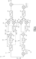
- FIG. 1 An example of a second filter 18 is illustrated more precisely on the figure 2 .
- the second filter 18 comprises two main blocks 34 which are the first main block 36 and the second main block 38, a first calculation unit 40, a second calculation unit 42 and an output adder 43.
- the first main block 36 and the second main block 38 are identical.
- each of the two main blocks 36 and 38 is capable of applying the same operations to an incident signal.
- the first main block 36 has three input branches 44, 46 and 48 and an output branch 50.
- the first main block 36 also includes an input adder 52, an input subtractor 54, a first processing channel 56, a second processing channel 58 and an output adder 59.
- the first branch 44 of the first main block 36 is directly connected to the input 18E of the filter 18.
- the second branch 46 of the first main block 36 is connected to the first calculation unit 40.
- the first calculation unit 40 includes an input 40E and an output 40S and the output 40S of the first calculation unit 40 is connected to the second branch 46 of the first main block 36.
- the input 40E of the first calculation unit 40 is directly connected to the input 18E of the filter 18.
- the first calculation unit 40 is an offset unit.
- the offset is illustrated schematically on the figure 2 by a box 40 in which it is written “z -N/2 ” with reference to a shift technique using the Z transform.
- N is in what follows, an even integer strictly greater than 4 so that the integer N/2 is greater than or equal to 2.
- the integer N corresponding to the number of samples, it is generally relatively large, in particular greater than or equal to 100.
- the third branch 48 of the first main block 36 is directly connected to the input 18E of the filter 18.
- the input adder 52 comprises two inputs 52E respectively connected to the first branch 44 of the first main block 36 and to the second branch 46 of the first main block 36.
- the input adder 52 also includes an output 52S connected to the input 56E of the first processing channel 56.
- the input adder 52 is capable of implementing an addition operation applied to the two output signals of the first branch 44 and the second branch 46 of the first main block 36, the signal obtained after addition being injected to the entry 56E of the first processing channel 56.
- the input adder 52 is able to perform the addition between a signal and the same signal shifted by N/2 points.
- the input subtractor 54 includes a first input 54E1 connected to the third branch 48 of the first main block 36 and a second input 54E2 connected to the second branch 46 of the first main block 36.
- the input subtractor 54 also includes a output 54S connected to the input 58S of the second processing channel 58.
- the input subtractor 54 is capable of implementing a difference operation applied between the two input signals of the third branch 48 and the second branch 46 of the first main block 36, the signal obtained after subtraction being injected into the input 58S of the second processing channel 58.
- the input subtractor 54 is capable of performing the subtraction between a signal and the same signal shifted by N/2 points.
- the first processing channel 56 successively comprises two subunits: a first subunit 60 and a second subunit 62.
- the two subunits 60 and 62 are in series.
- the calculated discrete Fourier transform is a fast Fourier transform denoted FFT N/2 .
- the second subunit 62 is also capable of implementing an operation of applying the inverse discrete Fourier transform to N/2 points on the selected points.
- the calculated discrete Fourier transform is a fast Fourier transform denoted IFFT N/2 .
- the second subunit 62 has an output connected to the output adder 59.
- the second processing channel 58 also includes a first subunit 60 and a second subunit 62 as well as two offset modules 70 and 72.
- the two subunits 60 and 62 of the second processing pathway 58 are similar to the two subunits 60 and 62 of the first processing pathway 56.
- the first shift module 70 is located between the input 58S of the second processing channel 58 and the first subunit 60.
- the first shift module 70 is capable of implementing a frequency translation of a value equal to the ratio between the sampling frequency and the number N.
- Such a first shift module 70 is symbolized by an arrow 74 on a multiplier 76, arrow 74 on which is written "e -2j ⁇ n/N " with reference to a usual translation technique which consists of multiplying the signal by a complex exponential well chosen.
- the second shift module 72 is located between the second subunit 60 and the output 58S of the second processing channel 58.
- the second shift module 72 is capable of implementing a frequency translation of a value opposite to the ratio between the sampling frequency and the number N.
- Such a second shift module 72 is symbolized by an arrow 78 on a multiplier 80, arrow 78 on which is written "e 2j ⁇ n/N " with reference to a usual translation technique which consists of multiplying the signal by a well-chosen complex exponential .
- the output adder 59 is connected respectively to the two outputs 56S and 58S of each processing channel 56 and 58 and outputs the sum of the two outputs 56S and 58S of each processing channel 56 and 58.
- the output 59S of the output adder 59 corresponds to the output branch 50 of the first main block 36.
- the second main block 38 comprises the same elements as the first main block 36. Only the signals injected at the input differ.
- the first input branch 82 of the second main block 38 is connected to the second input branch 46 of the first main block 36.
- the second input branch 84 of the second main block 38 is connected to a second calculation unit 42.
- the second calculation unit 42 includes an input 42E and an output 42S and the output 42S of the second calculation unit 42 is connected to the second input branch 84 of the second main block 38.
- the input 42E of the second calculation unit 42 is directly connected to the input 18E of the filter 18.
- the second calculation unit 42 is an offset unit.
- the offset is illustrated schematically on the figure 2 by a box 42 in which it is written “z -N/2 ” with reference to a shift technique using the Z transform.
- the third input branch 86 of the second main block 38 is directly connected to the second input branch 46 of the first main block 36.
- the output adder 43 is connected to the output branch of each main block 36 and 38.
- the output 18S of the filter 18, which is connected to the output of the output adder 59, is crossed by a signal corresponding to the sum of the signals circulating in the output branches of each main block 36 and 38.
- the optimized architecture Figure 3 advantageously exploits the similarity between on the one hand the first processing channels 56 of the main blocks and on the other hand the second processing channels 58 of the main blocks.
- similarity in such a context is meant similar operations or treatments.
- the fact is used that in the first processing channels 34, the IFFT operations relate to the spectrum points corresponding to even indices whereas, in the second processing channels 34, IFFT operations concern the spectrum points corresponding to odd indices.
- the first processing channels 34 are shared by an intermediate adder, which makes it possible to use a single IFFT application unit at output instead of two in the case of figure 2 .
- the second processing channels 34 are shared by an intermediate adder, which makes it possible to use a single IFFT application unit at output for each second processing channel 34 as well as a single application unit of offset instead of two at output in the case of figure 2 .
- the final adder is replaced by a subtractor.
- Filter 18 of the Figure 3 is thus optimized with respect to filter 18 of the figure 2 since the filter 18 of the Figure 3 involves three resource-intensive operations, namely two IFFT operations and one shift operation.
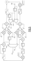
- a further improved architecture for filter 18 of the figure 2 and the filter 18 of the Figure 3 is offered to the Figure 4 .
- the architecture optimized for figure 4 advantageously exploits the similarity between on the one hand the first processing channels 56 of the main blocks and on the other hand the second processing channels 58 of the main blocks.
- the FFT operation of a first processing channel 56 differs only from the FFT operation of the other first processing channel 56 by the application of offsets on the points on which the operation of FFT considered is applied.
- the FFT operation of a second processing channel 58 differs only from the FFT operation of the other second processing channel 58 by the application of offsets on the points on which the FFT operation considered is applied.
- the filter of the Figure 4 thus comprises two processing channels V1 and V2 which are summed at the output by a final adder.
- the second channel V2 includes the same succession of operations as the operations of the first channel V1.
- the second channel V2 differs only from the first channel V1 by the presence of a shift unit upstream of the succession of operations and the presence of a shift unit in the opposite direction downstream of the succession of operations.
- the operations applied between the two shift units which are the same as the operations of the first channel V1 are now described by the description of the first channel V1 which follows.
- the first channel V1 successively comprises an N/2 FFT unit 64, a signal preparation unit 88, two selection units 66, an adder 96 and an N/2 IFFT unit 62.
- the N/2 FFT unit 64 is capable of applying an N/2 point FFT to the signal coming from the input terminal 18E of the filter 18.
- the signal preparation unit 88 is used to prepare the signal to be sent for each selection unit.
- the signal preparation unit 88 only includes addition subunits 90 and shift subunits 92 and 94.
- the signal preparation unit 88 comprises an addition subunit and two shift subunits.
- the addition subunit 90 is capable of carrying out the addition between two input branches, a first input branch corresponding to the spectrum obtained at the output of the N/2 FFT unit and a second input branch comprising an N/2 shift subunit represented by a z -N/2 box.
- the second input branch thus corresponds to the spectrum obtained at the output of the N/2 FFT unit with an offset of N/2 points.
- the addition subunit 90 comprises two output branches, a first output branch connected directly to the first selection unit and a second output branch comprising an N/2 shift subunit represented by a box z - N/2 , the shift subunit of the second output branch being connected to the second selection unit.
- the selection units 66 are then connected to the adder 96 whose output is connected to the IFFT N/2 unit.
- the filter architecture 18 shown in Figure 4 is thus optimized with respect to filter 18 of the Figure 3 by the fact that two FFT operations which are very costly in terms of resources are no longer implemented.
- the filter 18 comprises the same elements as the filter 18 of the Figure 4 as well as two calculation extractors 98 and 99.
- the first calculation extractor 98 is used to export the result of the N-point FFT to the outside of the filter 18.
- the second calculation extractor 99 is used to partially implement the N/2 point IFFT on a signal injected from the outside into the adder located directly upstream of the IFFT application unit.
- the calculation of the N/2 FFT can be performed in another filter so that the presence of the N/2 FFT calculation unit is avoided.
- the filter architecture 18 proposed for the Figure 5 thus makes it possible to pool computing resources between several stages or computing devices.
- Such simplification principles correspond more generally to a method of simplifying a digital filter of a sampled signal using the aforementioned properties of switching stationary (shift, summation) and discrete non-stationary (FFT and IFFT) operations.
- Such a simplification method comprises at least one supply step S1, a gathering step S2, a switching step S3 and a construction step S4.
- a filter comprising first channels capable of obtaining a first output signal by implementing first operations, second channels capable of obtaining a second output signal by implementing second operations, and a unit for recombining the signals obtained at the output of the first channels and the second channels.
- the first operations and the second operations comprising at least the same succession of discrete non-stationary operations and stationary operations, the succession relating to operations common to the first and second operations.
- channels comprising discrete non-stationary operations relating to the same signal are gathered together, the first channels gathered comprising the non-stationary operations relating to a first signal and the second combined channels comprising non-stationary operations relating to a second signal.
- step S4 the filter corresponding to the last intermediate filter obtained is constructed.
- the process achieves a simplification in the sense that a saving of resources is made.
- At least one of the non-stationary and stationary operations is a discrete operation.
- the non-stationary operations comprise two operations reciprocal to each other.
- the two signals from the gathering step form a complete signal.
- the number of points of each signal is identical.
- the non-stationary operations are chosen from a group consisting of discrete Fourier transforms, discrete inverse Fourier transforms and frequency translations.
- the stationary operations are discrete operations in a group consisting of filtering carried out multiplicatively in frequency, a summation, a delay and a difference.
- the simplification process makes it possible to obtain a plurality of filters 18 performing the same function with more or less resources involved.
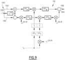
- Each aforementioned implementation of filter 18 is to be compared to filters 100 of figures 6 to 8 as well as with reference to the Figure 9 which corresponds to a block diagram illustrating the correct operation of the filter 100 of the figure 8 .
- the reference signs of the elements relating to the filter of the figures 1 to 5 are based on the reference sign 18 while the reference signs of the elements relating to the filter of figures 6 to 8 are based on the figure 2 .
- the term “filter 18” is used in the remainder of the description to designate a filter as described in one of the figures 1 to 5 And 11 to 14 while the term “filter 100” is used to designate a filter as described in one of the figures 6 to 8 .
- filter 18 includes an input 18E and an output 18S.
- the filter 100 has an input 100E and an output 100S.
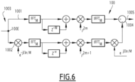
- the filter 100 comprises a first channel 1001, a second channel 1002, a transmitter 1003 and a mixer 1004.
- Input terminal 100E is suitable for receiving an input signal.
- the first channel 1001 is capable of obtaining a first output signal by implementing first operations.
- the first channel 1001 is suitable for implementing a first operation of first processing of the input signal to obtain a processed signal.
- the first processing is sending the input signal.
- the first channel 1001 is also capable of applying a discrete Fourier transform to M points on the processed signal to obtain M spectrum points of the processed signal, M being an integer strictly greater than 2, each spectrum point of the processed signal corresponding to the even indices of a spectral analysis at 2*M points of the processed signal and being identified bijectively by an index k, k being an even number between 0 and 2*M-1. In this case, the points are numbered from 0 to 2*M-1.
- the calculated discrete Fourier transform is a fast Fourier transform denoted FFT M.
- the first channel 1001 is also suitable for implementing a first operation of second processing of the spectrum points of the processed signal to obtain first selected points.
- the first channel 1001 is suitable for implementing the shift of the spectrum points of the processed signal of M samples to obtain shifted points and the calculation of the sum of the spectrum points of the processed signal and the shifted points.
- the offset is illustrated schematically on the Figure 6 by a box in which it is written “z -M ” with reference to a shift technique using the Z transform.
- the first channel 1001 is also suitable for implementing a first operation of applying the inverse discrete Fourier transform to M points on the first points selected to obtain a first signal.
- the calculated discrete Fourier transform is a fast Fourier transform denoted IFFT M.
- the first channel 1001 is also suitable for implementing a first third processing operation of the first signal to obtain a first output signal.
- the first operation of the third processing consists of transmitting the first output signal to the mixer 1004.
- the second channel 1002 is capable of obtaining a second output signal by implementing second operations.
- the second channel 1002 is suitable for implementing a second first processing operation of the input signal to obtain a processed signal.
- the second channel 1002 is capable of implementing a frequency translation of a value equal to the ratio between the sampling frequency and the number 2*M.
- the second channel 1002 is capable of implementing a second operation of applying a discrete Fourier transform to M points on the processed signal to obtain M spectrum points of the processed signal, each spectrum point of the processed signal corresponding to the indices odd numbers of a spectral analysis at 2*M points of the processed signal and being identified bijectively by an index k, k being an odd number between 0 and 2*M-1.
- the second channel 1002 is capable of implementing a second operation of second processing of the spectrum points of the processed signal to obtain second selected points.
- the second channel 1002 is thus suitable for implementing the shift of the spectrum points of the processed signal of M samples to obtain shifted points and the calculation of the sum of the spectrum points of the processed signal and the shifted points. From a signal perspective, offset is a time delay.
- the offset is illustrated schematically on the Figure 6 by a box in which it is written “z -M ” with reference to a shift technique using the Z transform.
- the second channel 1002 is also suitable for implementing a second operation of applying the inverse discrete Fourier transform to M points on the second points selected to obtain a second signal.
- the second channel 1002 is also capable of implementing a second third processing operation of the second signal to obtain a second output signal.
- the second channel 1002 is capable of implementing a frequency translation of a value opposite to the ratio between the sampling frequency and the number 2*M.
- the transmitter 1003 is capable of transmitting the input signal on the first channel 1001 and the second channel 1002.
- the mixer 1004 is capable of recombining the first output signal and the second output signal to obtain the filtered signal.
- the mixer 1004 is represented by a circle with a + sign and a - sign.
- the operation of the second filter 100 is now described with reference to an example of implementation of a method of filtering a digital input signal sampled at a sampling frequency to obtain a filtered signal.
- the method includes a providing step, a transmitting step, a step of obtaining a first output signal, a step of obtaining a second output signal and a recombination step.
- the input signal is supplied to the input terminal 100E of the second filter 100.
- the input signal is transmitted by the transmitter 1003 on the two channels 1001 and 1002.
- the fast Fourier transform at M points of the input signal is calculated to obtain the even order coefficients of a spectral analysis at 2*M points of the signal d 'entrance.
- a first operation is then carried out to implement the shift of the spectrum points of the processed signal of M samples to obtain shifted points and the calculation of the sum of the spectrum points of the processed signal and the shifted points.
- the first selected points are thus obtained.
- An application of the inverse discrete Fourier transform to M points is then applied to the first selected points to obtain a first output signal.
- the first output signal is sent to transmitter 1003.
- a frequency translation of a value equal to the ratio between the sampling frequency and the number 2*M is implemented. A processed signal is thus obtained.
- the fast Fourier transform at M points of the processed signal is calculated to obtain the odd order coefficients of a spectral analysis at 2*M points of the input signal.
- a second operation is then carried out to implement the shift of the spectrum points of the processed signal of M samples to obtain shifted points and the calculation of the sum of the spectrum points of the processed signal and the shifted points. Second selected points are thus obtained.
- An application of the inverse discrete Fourier transform to M points is then applied to the second selected points to obtain a second signal.
- the recombination step is then implemented using the mixer 1004 to obtain the filtered signal by making the difference between the first output signal and the second output signal.
- the method makes it possible to obtain a filtered signal more easily.
- the second filter 100 conforms to the embodiment of the Figure 7 .
- the second filter 100 differs from the second filter 100 depending on the embodiment of the Figure 6 by the operations that the first channel 1001 and second channel 1002 are capable of implementing and by the nature of the operations carried out during the recombination step.
- each of the first first processing and second processing operations consists of transmitting the signal considered.
- the second first processing operation comprises the implementation of a frequency translation of a value equal to the ratio between the sampling frequency and the number 2*M.
- the second processing consists of transmitting the signal in question.
- the second third processing operation comprises the implementation of a frequency translation applied to the second signal of a value equal to the opposite of the ratio between the sampling frequency and the number 2*M.
- the difference between the first output signal and the second output signal is calculated, to obtain a first calculation signal.
- the sum of the first output signal and the second output signal is then calculated, to obtain a second intermediate calculation signal.
- a shift of the second intermediate calculation signal by M samples is also implemented to obtain a second calculation signal.
- the sum of the first calculation signal and the second calculation signal is also calculated to obtain the filtered signal.
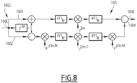
- the second filter 100 conforms to the embodiment of the Figure 6 .
- the second filter 100 according to the embodiment of the figure 8 differs from the second filter 100 depending on the embodiment of the Figure 6 by the operations that the first channel 1001 and second channel 1002 are suitable for implementing.
- the first first processing operation implements the offset of the input signal by M samples to obtain an offset signal and the calculation of the sum of the input signal and the offset signal.
- Each first second processing and third processing operation consists of transmitting the signal.
- the second first processing operation implements the shift of the input signal by M samples to obtain an shifted signal and the calculation of the sum of the input signal and the shifted signal.
- the second first processing operation then implements a frequency translation of a value equal to the ratio between the sampling frequency and the number 2*M.
- the second second processing operation consists of transmitting the signal.
- the second third processing operation implements a frequency translation applied to the second signal of a value equal to the opposite of the ratio between the sampling frequency and the number 2*M.
- a slice of 2M points a n is used for indices n which, by convention, will be such that 0 ⁇ n ⁇ 2*M-1.
- N N 1 x N 2 of two integers N 1 and N 2 .
- the discrete Fourier transform corresponds to the cascade of a discrete N 2- point Fourier transform and a discrete N 1- point Fourier transform
- the rapid time index n 1 arrives in the short time.
- the slow frequency index m 1 comes out in the running time and the fast frequency index m 2 comes out in the long time (“bit reverse”). and concludes with
- tweedle factor e ⁇ j 2 ⁇ not 1 ⁇ m 2 NOT 1 NOT 2
- the fastest varying output index is m 1 . Since it corresponds to the “fast” discrete Fourier transform, that is to say non-multiplexed.
- the output order of the frequencies is not the natural order: in fact, first come out the m worth 0 modulo N 1 then the m worth 1 and so on until the m worth N 1 - 1 always 0 modulo N 1 ; this order is called “bit reverse” because it corresponds to reversing the binary representation of the index to obtain the output rank (for a number of points in power of 2).
- the slow frequency index m 1 arrives in the current time and the fast frequency index m 2 arrives in the long time (“bit reverse”).
- the rapid time index n 1 stands out in the short time.
- the realization is carried out as the cascade of a discrete Fourier transform with N 2 points multiplexed by N 1 and a discrete Fourier transform with N 1 points not multiplexed.
- the “tweedle factor” is placed between the two discrete Fourier transform stages.
- the first discrete Fourier transform carried out being multiplexed, this decomposition accommodates parallelized input data; multiplexing then transforms into parallel processing.
- ⁇ m the spectral response of the filter
- the filtering corresponds to filtering adapted to a given signal (a received pulse for example)
- the filters 18 of figures 2 to 5 have reduced latency compared to the filters offered in the figures 6 to 8 .
- the latency is reduced by half by applying the principle illustrated by the assembly of the Figure 10 .
- FIR N The production of an FIR of maximum duration N is denoted FIR N following the principle presented previously. Such an implementation therefore has latencies equal to 2N.
- the latency of a filter is, in this context, the additional delay of the filter compared to the theoretical filter performing the same filtering
- Such an expression corresponds to the sum of the two responses, respectively first response and second response.
- the first response can be interpreted as the filtering of the x for times k to k - (N/2-1) by the first part of the FIR response while the second response is interpretable as the filtering of the x for times k - N/2 to k - (N-1) by the second part of the FIR response.
- N/2 FIR structure whose latency is N as illustrated by the assembly of the Figure 10 .
- Filter 18 therefore has reduced latency. Such a filter will be denoted subsequently FR N.
- the method comprises at least one step of supplying an input signal, a step of transmitting the input signal on two processing channels, a step of obtaining a first output signal, a step of obtaining of a second output signal, a step of applying a Fourier transform and a recombination step.
- a first output signal is obtained by implementing first operations on the first processing channel, the first operations comprising at least the application of filtering involving a discrete Fourier transform at M/2 points on a signal from the input signal, the filtering having a latency of M.
- second operations are carried out on the second processing channel, the second operations comprising at least the application of an offset of M/2 points to a signal from the input signal then the application of filtering involving a discrete Fourier transform at M/2 points on the shifted signal, the filtering having a latency of M.
- an inverse discrete Fourier transform is applied to M/2 points on the first signal to obtain M spectrum points of the first signal, M being an integer strictly greater than 2.
- the method comprises an operation of adding an input signal and the input signal shifted by N/2 points, the signal obtained after addition being the input signal of the first processing channel .
- the method comprises an operation of adding an input signal and the input signal shifted by N points, the signal obtained after addition being the input signal of the second channel of treatment.
- the N point shift operation is applied using two subunits 40 and 42.
- the first operations comprise a first processing of the input signal to obtain a processed signal, an operation of implementing the step of applying a discrete Fourier transform to M points on the processed signal , each spectrum point of the processed signal corresponding to the even indices of a spectral analysis at 2*M points of the processed signal and being identified bijectively by an index k, k being a even number between 0 and 2*M-1, a second processing of the spectrum points of the processed signal to obtain first selected points, an application of the inverse discrete Fourier transform to M points on the first selected points to obtain a first signal, and a third processing of the first signal to obtain a first output signal.
- the second operations comprise a first processing of the input signal to obtain a processed signal, an operation of implementing the step of applying a discrete Fourier transform to M points on the signal processed, each spectrum point of the processed signal corresponding to the odd indices of a spectral analysis at 2*M points of the processed signal and being identified bijectively by an index k, k being an even number between 0 and 2*M- 1, a second processing of the spectrum points of the processed signal to obtain first selected points, an application of the inverse discrete Fourier transform to M points on the first selected points to obtain a second signal, and a third processing of the second signal to obtain a second output signal.
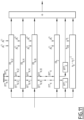
- each FR structure N has an intrinsic latency equal to N, such a development makes it possible to propose an architecture with zero latency as illustrated in the Figure 11 .
- Filter 18 of the Figure 11 comprises a plurality of stages corresponding to each member of the development.
- the first stage corresponds to the number 1, the second stage to the number 2, ..., the N/8th stage to the number N/8, the N/4th stage to the number N/4 and the N/2- th floor at number N/2.
- Filter 18 uses the capacity of one stage to perform an FFT and an IFFT for the next stage.
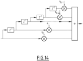
- each k-th channel FR k is formed by elements allowing the production of an FIR with k coefficients delayed by k.
- the FIR box is made by the FIR represented in Figure 12 .
- the FIR includes an adder capable of adding a first channel with a box z -1 followed by a mixer a 1 and a second channel comprising a mixer a 2 , the inputs of the two channels being combined.
- the FIR can thus be designated as a 0 + a 1 z -1 .
- a value of k is low when k is less than 256.
- the corresponding filter architecture 18 is that of the Figure 13 .
- the filter architecture 18 differs in particular at the first stage, the first stage comprising elements carrying out an operation FR K. Such an operation is visible on the Figure 14 .
- Such a filter 18 makes it possible to obtain zero latency by using additional resources which are now evaluated.
- the required resources include multiple elements.
- the required resources involve 2 (M+1) + 2 M + ... + 2 (K+2) additions for FR 2 structures K .2 x 2K additions for the FFT and IFFT at 2 K points and 2 K - 1 additions for the FIR part.
- the resources required to implement such a calculation also involve (M+4) + (M+3) + ... + (K+5) multiplications for the FR k structures, 2 x K/2 multiplications for the FFT and the IFFT has 2 K points and 2 K multiplications for the FIR part.
- the proposed filter 18 thus has zero latency.
- the filter 18 is based in both cases on a Russian doll structure in which each Russian doll is a calculation stage used for the FFT for one stage and the IFFT for another stage.
- the filter 18 thus uses the latency advantageously to produce a delay ensuring at the end zero latency for the total filtering carried out.
- a method can be derived for filtering a digital input signal sampled at a sampling frequency to obtain a filtered signal, the method comprising at least one supply step, a transmission step, a step of obtaining a first output signal, a step of obtaining a second output signal and an application step.
- an input signal is provided.
- the input signal is transmitted over two processing channels.
- the corresponding obtaining step comprises the implementation of first operations on the first processing channel, the first operations comprising at least the application of a discrete Fourier transform to M/2 p points on a signal from the input signal, the integer p being greater than or equal to 1.
- Such an obtaining step corresponds to the use of a latency of value M/2 p to generate a delay making it possible to use the FFT or IFFT calculations for another stage in a synchronized manner.
- the corresponding obtaining step comprises the implementation of second operations on the second processing channel, the second operations comprising at least the application of an offset of M/2 points to a signal from the input signal then the application of a discrete Fourier transform to M/2 p points on the shifted signal.
- Such an obtaining step can be interpreted as the use of a latency of value M/2 p to generate a delay allowing the FFT or IFFT calculations to be used for another stage in a synchronized manner.
- a discrete Fourier transform is applied to M/2 p points on the first signal to obtain M spectrum points of the first signal, M being an integer strictly greater than 2, the step application being implemented by the addition of the results of two processing channels.
- the method is implemented, and in particular at least the application step, for a plurality of values of p.
- the integer p increases by increment of 1.
- the first operations comprise a first processing of the input signal to obtain a processed signal, the signal on which the discrete Fourier transform at M/2 p points on a signal from the input signal is the processed signal , each spectrum point of the processed signal corresponding to the even indices of a spectral analysis at 2* M/2 p points of the processed signal and being identified bijectively by an index k, k being an even number between 0 and 2* M/2 p -1.
- the first operations further comprise a second processing of the spectrum points of the processed signal to obtain first selected points, an application of the inverse discrete Fourier transform to M/2 p points on the first selected points to obtain a first signal , and a third processing of the first signal to obtain a first output signal.
- the second operations comprising a first processing of the input signal to obtain a processed signal, the signal on which the discrete Fourier transform at M/2 p points on a signal coming from the input signal is the processed signal, each spectrum point of the processed signal corresponding to the odd indices of a spectral analysis at 2* M/2 p points of the processed signal and being identified bijectively by an index k, k being an even number between 0 and 2* M/2 p -1.
- the second operations further comprise a second processing of the spectrum points of the processed signal to obtain second selected points, an application of the inverse discrete Fourier transform to M points on the second selected points to obtain a second signal, and a third processing of the second signal to obtain a second output signal.
- these architectures introduce in principle a delay equal to 2N sampling periods compared to that of the response of the theoretical FIR.
- Such structures will be called basic structure.
- the proposed filters is derived from the basic FFT and IFFT structures.
- the proposed structure consists of decomposing the temporal response of the FIR into sections of sizes 2, 2, 4, 8, 16, ..., 2 N-1 whose sum is equal to 2 N.
- the longest sections correspond to the most delayed time domains of the temporal response.
- Each section is ensured by a latency substructure equal to the duration of the response that the substructure ensures so that its completion latency naturally introduces the delay associated with its position in the response.
- the substructures are produced by the combination of two basic structures of half size and offset by their half latency; this allows latency to be reduced by half compared to basic structures.
- the proposed architectures make it possible to resolve the intrinsic latency problem of basic structures; thanks to a strong optimization which exploits various decompositions of the FFT and the IFFT, it retains the characteristic of the initial architectures, based on FFT and IFFT, of requiring only few calculation resources (despite a certain inflation by compared to these initial architectures) while finding the characteristic of classic FIR architectures of not presenting latencies.
- the proposed architecture allows the use of large FIRs in any application requiring the lowest possible production latencies.
Claims (6)
- Verfahren zur Filterung eines mit einer Samplingfrequenz gesampelten digitalen Eingangssignals, um ein gefiltertes Signal zu erhalten, wobei das Verfahren von einem System durchgeführt wird, wobei das System ein Radar, ein Kommunikationssystem, ein Gegenmaßnahmensystem oder ein Detektionssystem ist, wobei das System eine Antenne und eine Verarbeitungskette aufweist, wobei das Verfahren mindestens einen Schritt umfasst:- Empfangen eines Eingangssignals durch die Antenne,- Sampeln des Eingangssignals,- Übertragen des Eingangssignals auf zwei Verarbeitungskanälen,- Erhalten eines ersten Ausgangssignals durch die Durchführung erster Operationen durch die Verarbeitungskette auf dem ersten Verarbeitungskanal, wobei die ersten Operationen mindestens die Anwendung einer Filterung aufweisen, die eine diskrete Fourier-Transformation mit M/2 Punkten auf ein Signal aus dem Eingangssignal beinhaltet, wobei die Filterung eine Latenz von M aufweist,- Erhalten eines zweiten Ausgangssignals durch die Durchführung zweiter Operationen durch die Verarbeitungskette auf dem zweiten Verarbeitungskanal, wobei die zweiten Operationen mindestens die Anwendung einer Verschiebung von M/2 Punkten auf ein Signal aus dem Eingangssignal, dann die Anwendung einer Filterung aufweisen, die eine diskrete Fourier-Tansformation mit M/2 Punkten auf das verschobene Signal beinhaltet, wobei die Filterung eine Latenz von M aufweist,- Anwenden einer inversen diskreten Fourier-Transformation mit M/2 Punkten auf das erste Signal, um M Punkte des Spektrums des ersten Signals zu erhalten, wobei M eine Ganzzahl strikt größer als 2 ist, und- Rekombinieren der Ergebnisse der beiden Verarbeitungskanäle.
- Verfahren nach Anspruch 1, wobei das Verfahren eine Operation einer Addition eines Eingangssignals und des um M Punkte verschobenen Eingangssignals aufweist, wobei das nach der Addition erhaltene Signal das Eingangssignal des ersten Verarbeitungskanals ist.
- Verfahren nach Anspruch 1 oder 2, wobei das Verfahren eine Operation einer Addition eines Eingangssignals und des um 2*M Punkte verschobenen Eingangssignals aufweist, wobei das nach der Addition erhaltene Signal das Eingangssignal des zweiten Verarbeitungskanals ist.
- Verfahren nach Anspruch 3, wobei die Operation der Verschiebung um 2*M Punkte mit Hilfe von zwei Untereinheiten (40, 42) angewendet wird.
- Verfahren nach einem der Ansprüche 1 bis 4, wobei die ersten Operationen eine erste Verarbeitung des Eingangssignals aufweisen, um ein verarbeitetes Signal zu erhalten, wobei das Signal, auf das eine diskrete Fourier-Transformation mit M Punkten angewendet wird, das verarbeitete Signal ist, wobei jeder Punkt des Spektrums des verarbeiteten Signals den geraden Indizes einer 2*M-Punkt-Spektralanalyse des verarbeiteten Signals entspricht und bijektiv durch einen Index k markiert wird, wobei k eine gerade Zahl zwischen 0 und 2*M-1 ist,wobei die ersten Operationen ferner umfassen:- eine zweite Verarbeitung der Punkte des Spektrums des verarbeiteten Signals, um ausgewählte erste Punkte zu erhalten,- eine Anwendung der inversen diskreten Fourier-Transformation mit M Punkten auf die ausgewählten ersten Punkte, um ein erstes Signal zu erhalten, und- eine dritte Verarbeitung des ersten Signals, um ein erstes Ausgangssignal zu erhalten, unddie zweiten Operationen eine erste Verarbeitung des Eingangssignals aufweisen, um ein verarbeitetes Signal zu erhalten, wobei das Signal, auf das eine diskrete Fourier-Transformation mit M Punkten angewendet wird, das verarbeitete Signal ist, wobei jeder Punkt des Spektrums des verarbeiteten Signals den ungeraden Indizes einer 2*M-Punkt-Spektralanalyse des verarbeiteten Signals entspricht und bijektiv durch einen Index k markiert wird, wobei k eine gerade Zahl zwischen 0 und 2*M-1 ist,wobei die zweiten Operationen ferner umfassen:- eine zweite Verarbeitung der Punkte des Spektrums des verarbeiteten Signals, um ausgewählte zweite Punkte zu erhalten,- eine Anwendung der inversen diskreten Fourier-Transformation mit M Punkten auf die ausgewählten zweiten Punkte, um ein zweites Signal zu erhalten, und- eine dritte Verarbeitung des zweiten Signals, um ein zweites Ausgangssignal zu erhalten.
- System, wobei das System ein Radar, ein Kommunikationssystem, ein Gegenmaßnahmensystem oder ein Detektionssystem ist, wobei das System eine Antenne und eine Verarbeitungskette aufweist, wobei das System zur Durchführung des Verfahrens nach einem der Ansprüche 1 bis 5 geeignet ist.
Applications Claiming Priority (1)
| Application Number | Priority Date | Filing Date | Title |
|---|---|---|---|
| FR1911523A FR3102264B1 (fr) | 2019-10-16 | 2019-10-16 | Procédé de filtrage avec latence réduite et dispositifs associés |
Publications (2)
| Publication Number | Publication Date |
|---|---|
| EP3809286A1 EP3809286A1 (de) | 2021-04-21 |
| EP3809286B1 true EP3809286B1 (de) | 2023-11-01 |
Family
ID=71661882
Family Applications (1)
| Application Number | Title | Priority Date | Filing Date |
|---|---|---|---|
| EP20201823.0A Active EP3809286B1 (de) | 2019-10-16 | 2020-10-14 | Verfahren zur filterung mit reduzierter latenzzeit, und entsprechende vorrichtungen |
Country Status (4)
| Country | Link |
|---|---|
| US (1) | US20210117498A1 (de) |
| EP (1) | EP3809286B1 (de) |
| FR (1) | FR3102264B1 (de) |
| IL (1) | IL278046A (de) |
Families Citing this family (4)
| Publication number | Priority date | Publication date | Assignee | Title |
|---|---|---|---|---|
| FR3133236A1 (fr) | 2022-03-01 | 2023-09-08 | Thales | Procédé de formation de faisceaux et dispositifs associés |
| FR3133234A1 (fr) | 2022-03-01 | 2023-09-08 | Thales | Procédé de formation de faisceaux paramétrables et dispositifs associés |
| FR3133235A1 (fr) | 2022-03-01 | 2023-09-08 | Thales | Procédé de formation de voies en émission paramétrables et dispositifs associés |
| FR3133233A1 (fr) | 2022-03-01 | 2023-09-08 | Thales | Procédé de formation de voies d'émission et dispositifs associés |
Family Cites Families (4)
| Publication number | Priority date | Publication date | Assignee | Title |
|---|---|---|---|---|
| WO2007100666A2 (en) * | 2006-02-22 | 2007-09-07 | University Of Akron | Interleaved method for parallel implementation of the fast fourier transform |
| WO2011033342A1 (en) * | 2009-09-18 | 2011-03-24 | Stmicroelectronics Sa | Receive unit for reception of a satellite signal |
| EP3211538A4 (de) * | 2015-05-08 | 2018-01-17 | Huawei Technologies Co. Ltd. | Signalverarbeitungsverfahren und -vorrichtung |
| FR3049131B1 (fr) * | 2016-03-18 | 2018-04-06 | Thales | Procede de filtrage d'un signal d'entree numerique et filtre associe |
-
2019
- 2019-10-16 FR FR1911523A patent/FR3102264B1/fr active Active
-
2020
- 2020-10-14 EP EP20201823.0A patent/EP3809286B1/de active Active
- 2020-10-14 IL IL278046A patent/IL278046A/en unknown
- 2020-10-15 US US17/071,780 patent/US20210117498A1/en active Pending
Also Published As
| Publication number | Publication date |
|---|---|
| US20210117498A1 (en) | 2021-04-22 |
| EP3809286A1 (de) | 2021-04-21 |
| IL278046A (en) | 2021-04-29 |
| FR3102264A1 (fr) | 2021-04-23 |
| FR3102264B1 (fr) | 2023-06-30 |
Similar Documents
| Publication | Publication Date | Title |
|---|---|---|
| EP3809287B1 (de) | Verfahren zur vereinfachung eines filters und entsprechende vorrichtungen | |
| EP3809286B1 (de) | Verfahren zur filterung mit reduzierter latenzzeit, und entsprechende vorrichtungen | |
| EP3809288B1 (de) | Filterverfahren mit null-latenzzeit, und entsprechende vorrichtungen | |
| FR3049131A1 (fr) | Procede de filtrage d'un signal d'entree numerique et filtre associe | |
| EP2484075B1 (de) | Systeme für die Mehrträger-Übertragung von digitalen Daten und Übertragungsverfahren mit derartigen Systemen | |
| EP0204603B1 (de) | Schnelle Rechnerschaltung für die direkte oder umgekehrte Cosinustransformation eines diskreten Signals | |
| EP2856663B1 (de) | Verfahren zur drahtlosen kommunikation mit einem mehrfachantennenempfänger | |
| WO2010029225A1 (fr) | Systeme de transmission numerique multiporteuse d'un signal utilisant des bancs de filtres et le prechargement de memoires pour l'initialisation | |
| FR2525054A1 (fr) | Emetteur concu pour l'emission de signaux modules en frequence | |
| EP0259231A1 (de) | Vorrichtung zur Ermittlung der digitalen Transformation eines Signals | |
| EP1216557B1 (de) | Verfahren zur übertragung eines mit offset modulierten biorthogonalen mehrträgersignals (bfdm/om) | |
| EP1113634A1 (de) | Verfahren zur Übertragungskanalschätzung | |
| EP0688476B1 (de) | Verfahren und vorrichtung zum filtern eines digitalen zeitsignals und anwendung für echokorrektur in einem übertragungskanal | |
| EP0970562B1 (de) | Digitalfilter für fraktionale verzögerungen | |
| EP0175623A1 (de) | Einrichtung zur Echtzeitdigitalsignalverarbeitung durch Faltung | |
| EP1135855A1 (de) | Digitales filter mit paralleler architektur und spreizspektrumempfänger mit einem solchen filter | |
| FR3104859A1 (fr) | Procede de decouplage de signaux dans des systemes d’emission/reception | |
| EP1101283B1 (de) | Verfahren zur herstellung von digitalen nyquist filtern ohne störungen zwischen symbolen und entsprechende filteranordnung | |
| EP4239904A1 (de) | Verfahren zur erzeugung von parametrierbaren strahlen und vorrichtungen dafür | |
| EP4239902A1 (de) | Verfahren zur bildung von parametrierbaren emissionspfaden und zugehörige vorrichtungen | |
| EP4239901A1 (de) | Strahlformungsverfahren und zugehörige vorrichtungen | |
| EP4239900A1 (de) | Verfahren zur herstellung von emissionspfaden und zugehörige vorrichtungen | |
| EP4239903A1 (de) | Verfahren zur kalibrierung eines strahlformungssystems und zugehörige vorrichtungen | |
| WO2008152322A2 (fr) | Procede et dispositif electronique de decalage frequentiel d'un signal analogique, en particulier pour la telephonie mobile. | |
| FR2536541A1 (fr) | Systeme simplifie d'analyse spectrale a exploitation de phase |
Legal Events
| Date | Code | Title | Description |
|---|---|---|---|
| PUAI | Public reference made under article 153(3) epc to a published international application that has entered the european phase |
Free format text: ORIGINAL CODE: 0009012 |
|
| STAA | Information on the status of an ep patent application or granted ep patent |
Free format text: STATUS: THE APPLICATION HAS BEEN PUBLISHED |
|
| AK | Designated contracting states |
Kind code of ref document: A1 Designated state(s): AL AT BE BG CH CY CZ DE DK EE ES FI FR GB GR HR HU IE IS IT LI LT LU LV MC MK MT NL NO PL PT RO RS SE SI SK SM TR |
|
| AX | Request for extension of the european patent |
Extension state: BA ME |
|
| STAA | Information on the status of an ep patent application or granted ep patent |
Free format text: STATUS: REQUEST FOR EXAMINATION WAS MADE |
|
| 17P | Request for examination filed |
Effective date: 20210923 |
|
| RBV | Designated contracting states (corrected) |
Designated state(s): AL AT BE BG CH CY CZ DE DK EE ES FI FR GB GR HR HU IE IS IT LI LT LU LV MC MK MT NL NO PL PT RO RS SE SI SK SM TR |
|
| STAA | Information on the status of an ep patent application or granted ep patent |
Free format text: STATUS: EXAMINATION IS IN PROGRESS |
|
| 17Q | First examination report despatched |
Effective date: 20221115 |
|
| GRAP | Despatch of communication of intention to grant a patent |
Free format text: ORIGINAL CODE: EPIDOSNIGR1 |
|
| STAA | Information on the status of an ep patent application or granted ep patent |
Free format text: STATUS: GRANT OF PATENT IS INTENDED |
|
| P01 | Opt-out of the competence of the unified patent court (upc) registered |
Effective date: 20230502 |
|
| RIC1 | Information provided on ipc code assigned before grant |
Ipc: G01S 7/288 20060101ALI20230524BHEP Ipc: H03H 17/02 20060101ALI20230524BHEP Ipc: G06F 17/14 20060101AFI20230524BHEP |
|
| INTG | Intention to grant announced |
Effective date: 20230609 |
|
| GRAS | Grant fee paid |
Free format text: ORIGINAL CODE: EPIDOSNIGR3 |
|
| GRAA | (expected) grant |
Free format text: ORIGINAL CODE: 0009210 |
|
| STAA | Information on the status of an ep patent application or granted ep patent |
Free format text: STATUS: THE PATENT HAS BEEN GRANTED |
|
| AK | Designated contracting states |
Kind code of ref document: B1 Designated state(s): AL AT BE BG CH CY CZ DE DK EE ES FI FR GB GR HR HU IE IS IT LI LT LU LV MC MK MT NL NO PL PT RO RS SE SI SK SM TR |
|
| REG | Reference to a national code |
Ref country code: GB Ref legal event code: FG4D Free format text: NOT ENGLISH |
|
| REG | Reference to a national code |
Ref country code: CH Ref legal event code: EP |
|
| REG | Reference to a national code |
Ref country code: IE Ref legal event code: FG4D Free format text: LANGUAGE OF EP DOCUMENT: FRENCH |
|
| REG | Reference to a national code |
Ref country code: DE Ref legal event code: R096 Ref document number: 602020020165 Country of ref document: DE |
|
| REG | Reference to a national code |
Ref country code: LT Ref legal event code: MG9D |
|
| REG | Reference to a national code |
Ref country code: NL Ref legal event code: MP Effective date: 20231101 |
|
| PG25 | Lapsed in a contracting state [announced via postgrant information from national office to epo] |
Ref country code: GR Free format text: LAPSE BECAUSE OF FAILURE TO SUBMIT A TRANSLATION OF THE DESCRIPTION OR TO PAY THE FEE WITHIN THE PRESCRIBED TIME-LIMIT Effective date: 20240202 |
|
| PG25 | Lapsed in a contracting state [announced via postgrant information from national office to epo] |
Ref country code: IS Free format text: LAPSE BECAUSE OF FAILURE TO SUBMIT A TRANSLATION OF THE DESCRIPTION OR TO PAY THE FEE WITHIN THE PRESCRIBED TIME-LIMIT Effective date: 20240301 |
|
| PG25 | Lapsed in a contracting state [announced via postgrant information from national office to epo] |
Ref country code: LT Free format text: LAPSE BECAUSE OF FAILURE TO SUBMIT A TRANSLATION OF THE DESCRIPTION OR TO PAY THE FEE WITHIN THE PRESCRIBED TIME-LIMIT Effective date: 20231101 |
|
| REG | Reference to a national code |
Ref country code: AT Ref legal event code: MK05 Ref document number: 1628021 Country of ref document: AT Kind code of ref document: T Effective date: 20231101 |
|
| PG25 | Lapsed in a contracting state [announced via postgrant information from national office to epo] |
Ref country code: NL Free format text: LAPSE BECAUSE OF FAILURE TO SUBMIT A TRANSLATION OF THE DESCRIPTION OR TO PAY THE FEE WITHIN THE PRESCRIBED TIME-LIMIT Effective date: 20231101 |
|
| PG25 | Lapsed in a contracting state [announced via postgrant information from national office to epo] |
Ref country code: AT Free format text: LAPSE BECAUSE OF FAILURE TO SUBMIT A TRANSLATION OF THE DESCRIPTION OR TO PAY THE FEE WITHIN THE PRESCRIBED TIME-LIMIT Effective date: 20231101 |
|
| PG25 | Lapsed in a contracting state [announced via postgrant information from national office to epo] |
Ref country code: NL Free format text: LAPSE BECAUSE OF FAILURE TO SUBMIT A TRANSLATION OF THE DESCRIPTION OR TO PAY THE FEE WITHIN THE PRESCRIBED TIME-LIMIT Effective date: 20231101 Ref country code: LT Free format text: LAPSE BECAUSE OF FAILURE TO SUBMIT A TRANSLATION OF THE DESCRIPTION OR TO PAY THE FEE WITHIN THE PRESCRIBED TIME-LIMIT Effective date: 20231101 Ref country code: IS Free format text: LAPSE BECAUSE OF FAILURE TO SUBMIT A TRANSLATION OF THE DESCRIPTION OR TO PAY THE FEE WITHIN THE PRESCRIBED TIME-LIMIT Effective date: 20240301 Ref country code: GR Free format text: LAPSE BECAUSE OF FAILURE TO SUBMIT A TRANSLATION OF THE DESCRIPTION OR TO PAY THE FEE WITHIN THE PRESCRIBED TIME-LIMIT Effective date: 20240202 Ref country code: BG Free format text: LAPSE BECAUSE OF FAILURE TO SUBMIT A TRANSLATION OF THE DESCRIPTION OR TO PAY THE FEE WITHIN THE PRESCRIBED TIME-LIMIT Effective date: 20240201 Ref country code: AT Free format text: LAPSE BECAUSE OF FAILURE TO SUBMIT A TRANSLATION OF THE DESCRIPTION OR TO PAY THE FEE WITHIN THE PRESCRIBED TIME-LIMIT Effective date: 20231101 Ref country code: PT Free format text: LAPSE BECAUSE OF FAILURE TO SUBMIT A TRANSLATION OF THE DESCRIPTION OR TO PAY THE FEE WITHIN THE PRESCRIBED TIME-LIMIT Effective date: 20240301 |