EP3809211B1 - System with a data generating unit in a gripping arm - Google Patents
System with a data generating unit in a gripping arm Download PDFInfo
- Publication number
- EP3809211B1 EP3809211B1 EP19203237.3A EP19203237A EP3809211B1 EP 3809211 B1 EP3809211 B1 EP 3809211B1 EP 19203237 A EP19203237 A EP 19203237A EP 3809211 B1 EP3809211 B1 EP 3809211B1
- Authority
- EP
- European Patent Office
- Prior art keywords
- gripping
- data
- sensor
- designed
- unit
- Prior art date
- Legal status (The legal status is an assumption and is not a legal conclusion. Google has not performed a legal analysis and makes no representation as to the accuracy of the status listed.)
- Active
Links
- 238000001514 detection method Methods 0.000 claims description 24
- 239000000463 material Substances 0.000 claims description 20
- 238000007781 pre-processing Methods 0.000 claims description 16
- 230000005540 biological transmission Effects 0.000 claims description 15
- 238000012545 processing Methods 0.000 claims description 7
- 230000001939 inductive effect Effects 0.000 claims description 5
- 230000005291 magnetic effect Effects 0.000 claims description 4
- 238000012544 monitoring process Methods 0.000 claims description 3
- 230000003287 optical effect Effects 0.000 claims description 3
- 230000008859 change Effects 0.000 description 13
- 238000000034 method Methods 0.000 description 7
- 230000002596 correlated effect Effects 0.000 description 4
- 239000002184 metal Substances 0.000 description 4
- 230000006835 compression Effects 0.000 description 3
- 238000007906 compression Methods 0.000 description 3
- 230000000694 effects Effects 0.000 description 3
- 238000004146 energy storage Methods 0.000 description 3
- 238000011156 evaluation Methods 0.000 description 3
- 230000008569 process Effects 0.000 description 3
- 230000008901 benefit Effects 0.000 description 2
- 239000003990 capacitor Substances 0.000 description 2
- 238000004140 cleaning Methods 0.000 description 2
- 239000004020 conductor Substances 0.000 description 2
- 239000011521 glass Substances 0.000 description 2
- 230000001965 increasing effect Effects 0.000 description 2
- 238000012423 maintenance Methods 0.000 description 2
- 230000006855 networking Effects 0.000 description 2
- 241001620634 Roger Species 0.000 description 1
- 238000005452 bending Methods 0.000 description 1
- 238000010276 construction Methods 0.000 description 1
- 230000002950 deficient Effects 0.000 description 1
- 230000001419 dependent effect Effects 0.000 description 1
- 238000011161 development Methods 0.000 description 1
- 230000018109 developmental process Effects 0.000 description 1
- 238000009826 distribution Methods 0.000 description 1
- 239000003814 drug Substances 0.000 description 1
- 229940079593 drug Drugs 0.000 description 1
- 239000000428 dust Substances 0.000 description 1
- 239000003302 ferromagnetic material Substances 0.000 description 1
- 238000001746 injection moulding Methods 0.000 description 1
- 238000009413 insulation Methods 0.000 description 1
- 238000002372 labelling Methods 0.000 description 1
- 230000004807 localization Effects 0.000 description 1
- 230000007257 malfunction Effects 0.000 description 1
- 238000004519 manufacturing process Methods 0.000 description 1
- 239000002304 perfume Substances 0.000 description 1
- 238000013024 troubleshooting Methods 0.000 description 1
Images

Classifications
-
- G—PHYSICS
- G05—CONTROLLING; REGULATING
- G05B—CONTROL OR REGULATING SYSTEMS IN GENERAL; FUNCTIONAL ELEMENTS OF SUCH SYSTEMS; MONITORING OR TESTING ARRANGEMENTS FOR SUCH SYSTEMS OR ELEMENTS
- G05B19/00—Programme-control systems
- G05B19/02—Programme-control systems electric
- G05B19/04—Programme control other than numerical control, i.e. in sequence controllers or logic controllers
- G05B19/042—Programme control other than numerical control, i.e. in sequence controllers or logic controllers using digital processors
-
- B—PERFORMING OPERATIONS; TRANSPORTING
- B25—HAND TOOLS; PORTABLE POWER-DRIVEN TOOLS; MANIPULATORS
- B25J—MANIPULATORS; CHAMBERS PROVIDED WITH MANIPULATION DEVICES
- B25J13/00—Controls for manipulators
- B25J13/08—Controls for manipulators by means of sensing devices, e.g. viewing or touching devices
-
- B—PERFORMING OPERATIONS; TRANSPORTING
- B25—HAND TOOLS; PORTABLE POWER-DRIVEN TOOLS; MANIPULATORS
- B25J—MANIPULATORS; CHAMBERS PROVIDED WITH MANIPULATION DEVICES
- B25J15/00—Gripping heads and other end effectors
- B25J15/02—Gripping heads and other end effectors servo-actuated
- B25J15/0206—Gripping heads and other end effectors servo-actuated comprising articulated grippers
- B25J15/0213—Gripping heads and other end effectors servo-actuated comprising articulated grippers actuated by gears
-
- B—PERFORMING OPERATIONS; TRANSPORTING
- B25—HAND TOOLS; PORTABLE POWER-DRIVEN TOOLS; MANIPULATORS
- B25J—MANIPULATORS; CHAMBERS PROVIDED WITH MANIPULATION DEVICES
- B25J9/00—Programme-controlled manipulators
- B25J9/16—Programme controls
- B25J9/1674—Programme controls characterised by safety, monitoring, diagnostic
-
- B—PERFORMING OPERATIONS; TRANSPORTING
- B25—HAND TOOLS; PORTABLE POWER-DRIVEN TOOLS; MANIPULATORS
- B25J—MANIPULATORS; CHAMBERS PROVIDED WITH MANIPULATION DEVICES
- B25J9/00—Programme-controlled manipulators
- B25J9/16—Programme controls
- B25J9/1694—Programme controls characterised by use of sensors other than normal servo-feedback from position, speed or acceleration sensors, perception control, multi-sensor controlled systems, sensor fusion
-
- B—PERFORMING OPERATIONS; TRANSPORTING
- B65—CONVEYING; PACKING; STORING; HANDLING THIN OR FILAMENTARY MATERIAL
- B65G—TRANSPORT OR STORAGE DEVICES, e.g. CONVEYORS FOR LOADING OR TIPPING, SHOP CONVEYOR SYSTEMS OR PNEUMATIC TUBE CONVEYORS
- B65G47/00—Article or material-handling devices associated with conveyors; Methods employing such devices
- B65G47/74—Feeding, transfer, or discharging devices of particular kinds or types
- B65G47/90—Devices for picking-up and depositing articles or materials
-
- B—PERFORMING OPERATIONS; TRANSPORTING
- B65—CONVEYING; PACKING; STORING; HANDLING THIN OR FILAMENTARY MATERIAL
- B65G—TRANSPORT OR STORAGE DEVICES, e.g. CONVEYORS FOR LOADING OR TIPPING, SHOP CONVEYOR SYSTEMS OR PNEUMATIC TUBE CONVEYORS
- B65G2203/00—Indexing code relating to control or detection of the articles or the load carriers during conveying
- B65G2203/02—Control or detection
- B65G2203/0266—Control or detection relating to the load carrier(s)
-
- B—PERFORMING OPERATIONS; TRANSPORTING
- B65—CONVEYING; PACKING; STORING; HANDLING THIN OR FILAMENTARY MATERIAL
- B65G—TRANSPORT OR STORAGE DEVICES, e.g. CONVEYORS FOR LOADING OR TIPPING, SHOP CONVEYOR SYSTEMS OR PNEUMATIC TUBE CONVEYORS
- B65G2203/00—Indexing code relating to control or detection of the articles or the load carriers during conveying
- B65G2203/04—Detection means
- B65G2203/042—Sensors
-
- B—PERFORMING OPERATIONS; TRANSPORTING
- B65—CONVEYING; PACKING; STORING; HANDLING THIN OR FILAMENTARY MATERIAL
- B65G—TRANSPORT OR STORAGE DEVICES, e.g. CONVEYORS FOR LOADING OR TIPPING, SHOP CONVEYOR SYSTEMS OR PNEUMATIC TUBE CONVEYORS
- B65G47/00—Article or material-handling devices associated with conveyors; Methods employing such devices
- B65G47/74—Feeding, transfer, or discharging devices of particular kinds or types
- B65G47/84—Star-shaped wheels or devices having endless travelling belts or chains, the wheels or devices being equipped with article-engaging elements
- B65G47/846—Star-shaped wheels or wheels equipped with article-engaging elements
- B65G47/847—Star-shaped wheels or wheels equipped with article-engaging elements the article-engaging elements being grippers
-
- G—PHYSICS
- G05—CONTROLLING; REGULATING
- G05B—CONTROL OR REGULATING SYSTEMS IN GENERAL; FUNCTIONAL ELEMENTS OF SUCH SYSTEMS; MONITORING OR TESTING ARRANGEMENTS FOR SUCH SYSTEMS OR ELEMENTS
- G05B2219/00—Program-control systems
- G05B2219/30—Nc systems
- G05B2219/39—Robotics, robotics to robotics hand
- G05B2219/39409—Design of gripper, hand
-
- G—PHYSICS
- G05—CONTROLLING; REGULATING
- G05B—CONTROL OR REGULATING SYSTEMS IN GENERAL; FUNCTIONAL ELEMENTS OF SUCH SYSTEMS; MONITORING OR TESTING ARRANGEMENTS FOR SUCH SYSTEMS OR ELEMENTS
- G05B2219/00—Program-control systems
- G05B2219/30—Nc systems
- G05B2219/39—Robotics, robotics to robotics hand
- G05B2219/39466—Hand, gripper, end effector of manipulator
-
- G—PHYSICS
- G05—CONTROLLING; REGULATING
- G05B—CONTROL OR REGULATING SYSTEMS IN GENERAL; FUNCTIONAL ELEMENTS OF SUCH SYSTEMS; MONITORING OR TESTING ARRANGEMENTS FOR SUCH SYSTEMS OR ELEMENTS
- G05B2219/00—Program-control systems
- G05B2219/30—Nc systems
- G05B2219/39—Robotics, robotics to robotics hand
- G05B2219/39527—Workpiece detector, sensor mounted in, near hand, gripper
-
- G—PHYSICS
- G05—CONTROLLING; REGULATING
- G05B—CONTROL OR REGULATING SYSTEMS IN GENERAL; FUNCTIONAL ELEMENTS OF SUCH SYSTEMS; MONITORING OR TESTING ARRANGEMENTS FOR SUCH SYSTEMS OR ELEMENTS
- G05B2219/00—Program-control systems
- G05B2219/30—Nc systems
- G05B2219/39—Robotics, robotics to robotics hand
- G05B2219/39528—Measuring, gripping force sensor build into hand
-
- G—PHYSICS
- G05—CONTROLLING; REGULATING
- G05B—CONTROL OR REGULATING SYSTEMS IN GENERAL; FUNCTIONAL ELEMENTS OF SUCH SYSTEMS; MONITORING OR TESTING ARRANGEMENTS FOR SUCH SYSTEMS OR ELEMENTS
- G05B2219/00—Program-control systems
- G05B2219/30—Nc systems
- G05B2219/39—Robotics, robotics to robotics hand
- G05B2219/39529—Force, torque sensor in wrist, end effector
-
- G—PHYSICS
- G05—CONTROLLING; REGULATING
- G05B—CONTROL OR REGULATING SYSTEMS IN GENERAL; FUNCTIONAL ELEMENTS OF SUCH SYSTEMS; MONITORING OR TESTING ARRANGEMENTS FOR SUCH SYSTEMS OR ELEMENTS
- G05B2219/00—Program-control systems
- G05B2219/30—Nc systems
- G05B2219/39—Robotics, robotics to robotics hand
- G05B2219/39531—Several different sensors integrated into hand
-
- G—PHYSICS
- G05—CONTROLLING; REGULATING
- G05B—CONTROL OR REGULATING SYSTEMS IN GENERAL; FUNCTIONAL ELEMENTS OF SUCH SYSTEMS; MONITORING OR TESTING ARRANGEMENTS FOR SUCH SYSTEMS OR ELEMENTS
- G05B2219/00—Program-control systems
- G05B2219/30—Nc systems
- G05B2219/39—Robotics, robotics to robotics hand
- G05B2219/39532—Gripping force sensor build into finger
-
- G—PHYSICS
- G05—CONTROLLING; REGULATING
- G05B—CONTROL OR REGULATING SYSTEMS IN GENERAL; FUNCTIONAL ELEMENTS OF SUCH SYSTEMS; MONITORING OR TESTING ARRANGEMENTS FOR SUCH SYSTEMS OR ELEMENTS
- G05B23/00—Testing or monitoring of control systems or parts thereof
- G05B23/02—Electric testing or monitoring
- G05B23/0205—Electric testing or monitoring by means of a monitoring system capable of detecting and responding to faults
- G05B23/0259—Electric testing or monitoring by means of a monitoring system capable of detecting and responding to faults characterized by the response to fault detection
- G05B23/0283—Predictive maintenance, e.g. involving the monitoring of a system and, based on the monitoring results, taking decisions on the maintenance schedule of the monitored system; Estimating remaining useful life [RUL]
Definitions
- the present invention relates to a system with a data generation unit.
- the invention relates to the "Internet of Things” (IoT), which is why the system according to the invention is also referred to as a “smart gripper unit".
- IoT usually describes the networking of objects with networks such as the Internet, so that these objects preferably communicate independently via these networks and can thus carry out various tasks for the owner.
- IoT In German-speaking countries, IoT is also known as "Industry 4.0".
- the area of application extends from a general supply of information to automatic orders to warning and emergency functions. This is possible in particular due to the increasing data networking of devices, the availability of information, e.g. via mobile phones, as well as the improved miniaturization of electronic components.
- Another main aspect of the "IoT” is that objects can communicate with one another independently of the hierarchy.
- a gripper arm such as in the DE29713510 and WO2006 / 089610 is known, forms part of a device, in particular a gripping device (also called "clip gripper”), which is designed to move a gripping portion of the gripping arm from an open position to a gripping position or vice versa.
- a gripping device also called "clip gripper”
- the gripping arm itself has a bore for mounting a bearing pin for pivotably securing the gripping arm in the device, and an energy storage device for moving the gripping portion of the gripping arm from the gripping position into the open position or vice versa.
- Such a gripper arm is basically known from the prior art and is used in the assembly line processing of containers.
- the containers are gripped at one station by means of a rotating transport or clamp star, which has a plurality of coaxially arranged gripping devices with at least one pair of gripping arms, and transported to the next station in the process.
- bottle-like containers for example drinks bottles made of glass or plastic, but also small bottles for drugs or perfume.
- the term also includes other glass or plastic containers which, similar to a bottle, in particular have a neck or a structure that tapers towards the opening.
- a gripping arm When gripping and transporting containers, a gripping arm is exposed to various compressive, tensile and / or shear forces. These forces can lead to bending or even breakage of the gripper arm and thereby limit, among other things, the operating time or service life of a gripper arm.
- a gripper arm comes into contact with several hundred thousand containers during its operating life and performs a gripping or opening movement just as often out.
- various mechanical components of the gripper arm such as the gripping section (for the container), the bore (for the bearing pin) and the actuating section (for the control means), are worn out, which in turn can lead to a malfunction.
- the prior art thus results in the need to identify the gripper arm, to determine the state of the gripper arm, in particular during operation, and / or to be able to make predictions about future suitability for operation or the expected service life. This should enable e.g. cleaning and filling systems for bottles to be better monitored, for example to identify maintenance work at an early stage and keep it short.
- the invention is based on the object of specifying a system with the aid of which properties and data of a gripper arm are recorded and made available for distribution.
- the data generation unit can also be referred to as a "Smartgripper data generation unit”.
- the at least one state variable can thus generally be understood to mean information about a mechanical and / or function-related state of the gripping device or specifically of the gripping arm.
- the detection of a number of gripping cycles is advantageous, for example, with regard to determining maintenance intervals that usually have to take place after a predetermined number of gripping cycles.
- the detection of the pressure force is based on the idea of determining whether the gripping device and in particular the gripping arm grips the container with sufficient force and thus ensures that the container is reliably held.
- a compressive force in the form of an external effect can also be reliably detected.
- the external influence can be understood here, for example, as stepping on the gripping device.
- the detection of material fatigue or material wear is used to detect signs of wear in order, for example, to be able to replace excessively worn gripping arms before they break. This reduces the downtimes of the gripping device and thus of the entire machine, since it is possible to react in good time.
- the detection of a break in a component of the gripping device and in particular a gripping arm is based on the idea of likewise reducing the downtime until the defective component is replaced.
- By detecting the break and in particular the localization of the broken component it is possible to initiate and carry out an exchange of the broken component in a targeted manner, since troubleshooting with regard to the broken component can be dispensed with.
- the detection unit has one or more sensors, which is / are arranged on the gripping device, for detecting the at least one state variable.
- the senor (s) is / are here preferably arranged on the gripper arm in such a way that they do not hinder the actual operation of a gripper arm, such as gripping, pivoting and holding.
- the data generation unit and especially the detection unit can be dimensioned in such a way that it does not form an extension or elevation on the gripper arm which in particular hinders the operation of the gripper arm.
- the shape of the data generation unit and especially the detection unit can be adapted to the shape of the gripper arm, i.e. designed and / or arranged in alignment and / or continuous (without jumps or steps) with the surface of the gripper arm.
- the one or more sensors is designed as a capacitive sensor.
- Such sensors can be used, for example, as distance sensors and detect a position of the gripping arm of the gripping device.
- a metal plate is arranged on oppositely opposing gripping arms of the gripping device.
- the metal plates form a plate capacitor, the capacitance of which depends on the distance between the two metal plates.
- the one sensor or the plurality of sensors is designed as a resistive sensor.
- an electrical resistance element in the form of a metal piece is arranged on the gripping arm.
- the resistance element is specifically arranged on a gripping area of the gripping arm.
- the gripping area of the gripping arm can be understood here to mean the area with which the container is gripped, that is to say against which the container rests in the gripped state. Because of its material and because of its thickness, the resistance element has a predetermined resistance value which can be easily detected. Because the resistance element is arranged on the gripping area, it is exposed to wear, which is reflected in a change in the resistance value. This change in resistance results from the diameter of the resistance element which is reduced by wear. The wear on the resistance element can thus be essentially correlated with wear on the gripping arm. If the resistance value falls below a predefined value, for example, sufficient wear can be detected so that a replacement can take place before the gripper arm breaks. Alternatively, the resistance element can also be incorporated in the gripping area within the material of the gripping arm.
- the resistive sensor can also be designed as a strain gauge.
- the way in which strain gauges work is based on a change in resistance due to mechanical deformation of the strain gauge. This makes it possible to determine a gripping force acting on the gripping arm, which is preferably positively correlated with a material expansion of the gripping arm.
- positively correlated can be understood to mean that the gripping force is higher, the greater the material expansion of the gripping arm.
- Such strain gauges nowadays have an accuracy with which it is possible to precisely detect even intrinsic material strains. Intrinsic material expansions can be understood here to mean material deformations that are not visible to the human eye.
- the one sensor or the plurality of sensors is designed as an inductive sensor.
- Such an embodiment of the sensor (s) makes it possible to detect a number of gripping cycles and / or an open and / or a closed state and / or an opening angle and / or an opening speed of the gripping device.
- the functioning of inductive sensors is usually based on a change in the inductivity of a coil integrated within the sensor due to a relative movement of the sensor to an object that changes the inductance.
- the object preferably has a ferromagnetic material or is formed from such a material.
- the inductive The sensor can for example be arranged on the gripper arm. By moving the gripper arm during the gripping movement, the inductance changes.
- the one or more sensors is designed as a magnetic sensor, e.g. as a Hall sensor.
- the functioning of such sensors is based, analogously to the functioning of inductive sensors, on a change in the magnetic field of the magnetic sensor.
- a number of gripping cycles and / or an open and / or a closed state and / or an opening angle and / or an opening speed of the gripping device can also be detected.
- the one or more sensors are designed as an optical sensor.
- the optical sensor is, for example, a laser sensor. This makes it possible, for example, to detect a distance between two gripping arms and thus an open and / or a closed state of a clamp gripper formed from two gripping arms.
- sensor configurations can be combined in any desired manner in order to be able to respond to configuration- and application-specific requirements.
- the above list of sensor types is not exhaustive. Rather, other types and types of sensors can also be used for the purposes of this invention.
- the sensors can also have a casing. This protects them from external influences such as moisture and / or dust.
- Another advantage of the data generation unit is its structure and / or material properties, which allow it to be arranged or used before, during and / or after the manufacturing process of the gripper arm.
- the data generation unit can be protected against high temperatures and / or pressures, for example by a surface insulation layer and / or a constant or uniformly shaped conductor layer structure, if the data generation unit is enclosed by the plastic during a plastic injection molding process of the gripper arm. Should the gripper arm consist of at least partially electrically conductive material, the data generation unit is preferably electrically isolated from this material.
- the data preprocessing unit is expediently set up to provide the generated status data for transmission by means of a data transmission unit.
- the provision is preferably made by means of the data preprocessing unit in the context of the generation and especially after the generation of the status data.
- the data can also be filtered before they are made available for transmission.
- the data generation unit is preferably connectable or connected to one or more external entities, in particular to a monitoring system, in such a way that the one or more external entities can be activated as a function of the recorded state variable for generating entity data.
- the entity data can then be part of the state data.
- external can be understood to mean that the entities are not part of the data generation unit.
- the data generation unit can also be retrofitted.
- retrofittable can be understood to mean that the data generation unit can be mounted in the manner of a plug-and-play method on gripping devices and / or gripping arms that have already been installed and are in use. This further increases the possibility of using the data generation unit.
- a gripping arm for a gripping device for gripping, holding and guiding particularly bottle-like containers, which are designed to pivot a gripping section of the gripping arm from an open position to a gripping position or vice versa.
- an energy storage device is preferred for the pivotable movement of the gripping section from the gripping position into the open position or vice versa.
- the gripper arm here has a data generation unit.
- the data generation unit is in particular the data generation unit already described above.
- the data transmission unit transmits the data of the gripper arm generated by the data generation unit to the data processing unit.
- a method for operating a data generation unit is also disclosed.
- the procedure consists of the following steps.
- At least one state variable of a gripping device is detected by means of at least one sensor.
- the at least one sensor is in particular the sensors already described in the context of the data generation unit.
- the status data generated are then made available for transmission by means of a data transmission unit.
- entity data of one or more external entities are also used to generate the status data.
- the status data generated receive more information for a later evaluation of a status of the gripping arm and / or the gripping device.
- a use of a data generation unit for generating status data which contains information about at least one detected status variable of a gripping device and for providing the generated status data for transmission to a data processing unit by means of a data transmission unit.
- the data generation unit is, in particular, the data generation unit already mentioned above.
- the data generation unit 2 shown is on a gripping arm 4 of a gripping device 6 (cf. FIGS. 3 and 4 ) arranged.
- the data generation unit 2 is used to generate status data which contain information about a status variable of the gripping device 6 and especially of the gripping arm 4.
- the gripping device 6 serves to grasp, hold and guide particularly bottle-like containers (cf. FIGS. 3 and 4 ).
- the data generation unit 2 has a detection unit 8 for detecting the at least one state variable.
- the at least one state variable can include, for example, a number of gripping cycles of the gripping device 6, a pressure force that acts on the gripping device 6 and in particular on the gripping arm 4, material fatigue / wear and tear as well as a break in a component of the gripping device 6, in particular the gripping arm 4 Roger that will.
- the data generation unit 2 has a data preprocessing unit 10 for generating the status data.
- the detection unit 8 is formed by a sensor 12a which is arranged in a gripping section 14 of the gripping arm 4.
- the gripping section 14 is understood here to mean the section of the gripping arm 4 with which the particularly bottle-like containers are gripped, that is to say with which the particularly bottle-like containers come into mechanical contact.
- the detection unit 8 can alternatively or additionally have further sensors 12.
- the sensor 12a is designed as a resistive sensor, which generates a sensor signal due to the electrical resistance and / or due to a change in the electrical resistance. Due to the fact that the resistive sensor 12a is arranged in the gripping section 14 of the gripping arm 4, it also comes into mechanical contact with the particularly bottle-like containers (not shown) and is subject to mechanical wear in the process. Due to the mechanical wear, material is also removed from the sensor 12, which leads to a change in the electrical resistance. This change in the electrical resistance can in turn be determined in the form of a change in the detected signal.
- the resistive sensor 12a In order to transmit the detected electrical resistance of the resistive sensor 12a to the data preprocessing unit 10, the resistive sensor 12a and thus the detection unit 8 are connected to the data preprocessing unit 10 (not shown here).
- the state variable to be detected which in this case is the already mentioned material fatigue / wear, is thus correlated with the detected electrical resistance value of the resistive sensor 12a.
- a breakage of a component and, in particular, a breakage of the gripping arm 4 of the gripping device 6 can also be detected in this way.
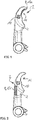
- Fig. 2 shows a gripping arm 4 with a data generation unit 2 according to a second embodiment.
- the gripping arm 4 is identical in construction to the gripping arms 4 according to FIG Fig. 1 educated.
- the data preprocessing unit also corresponds 10 of the data preprocessing unit 10 according to Fig. 1 .
- the detection unit 8 is formed as a strain gauge 12b.
- a strain gauge 12b is an embodiment of a resistive sensor 12a, the ascertainable resistance value of which varies as a function of an expansion or compression of the strain gauge 12b.
- the strain gauge 12b is arranged on one side of the gripping arm 4. In this way, for example, a compressive force on the gripping arm 4 can be determined which leads to an expansion or compression of the gripping arm 4.
- strain gauges 12b arranged on the gripping arms and can thereby be determined.
- the detected electrical resistance value or the detected change in the electrical resistance are transmitted to the data preprocessing unit 10.
- several strain gauges 12b can also be arranged on the surface of the gripper arm 4. This enables, in particular, a local resolution of the compressive force that is acting in each case.
- An external influence can also be determined by means of the detection unit 8 embodied as a strain gauge 12b.
- the external effect can be understood, for example, as a pressure force which does not occur during normal operation of the gripping device 6. For example, an unusually high compressive force occurs when someone steps on the gripping device 6 and especially the gripping arm 4.
- Fig. 3 shows a gripping device 6 with two opposing gripping arms 4 and a detection unit 8 with several sensors 12a, 12b, 12c.
- a strain gauge 12b is arranged on each of the gripping arms 4.
- each gripping section 14 has a resistive sensor 12a for detecting material fatigue / wear within the gripping section 14.
- two capacitive sensors 12c are arranged on the gripping device 6 on an outside, that is to say opposite the gripping section 14.
- each gripping arm 4 has a capacitive sensor 12c.
- the two capacitive sensors 12c thus form a plate capacitor whose detectable capacitance value is dependent on a distance between the two capacitive sensors 12c.
- a transport device 16 which has a plurality of gripping devices 6 on the circumferential side. Their gripping arms 4 are directed radially outward. Because of this configuration, the transport device 16 is also referred to as a transport star.
- Each of the gripping devices 6 and especially each gripping arm 4 of the transport device 16 has a data generation unit 2 with a detection unit 8 and a data preprocessing unit 10 (not shown). Alternatively, only one data preprocessing unit 10 is provided for the detection units 8 of the gripping devices 6 of the entire transport device 16.
- the detection units 8 here have at least one of the sensors 12a, 12b, 12c already mentioned above, so that at least one of the state variables also already mentioned can be detected. This configuration makes it possible to detect the state variables of each gripping device 6 and especially even of each gripping arm 4 of the transport device 16 and to make them available for an evaluation.
- the data preprocessing unit 10 is set up to generate state data from the at least one recorded state variable.
- the at least one recorded state variable is only formatted in a data format and made available for transmission by means of a data transmission unit (not shown here).
- the at least one recorded state variable can also be pre-filtered before it is converted into the state data.
- the data generation unit 2 can be or is connected to one or more external entities 18.
- an external entity 18 is provided, which is designed as a surveillance system, for example as a surveillance camera.
- the external entity 18 can be activated as a function of the at least one recorded state variable and generates entity data in the process.
- the external entity 18 designed as a camera can be activated and thus provide image data on the cause of the increased pressure load.
- the entity data generated thereby are also part of the status data and are provided by the data preprocessing unit 10 together with the detected status variable or variables for transmission.
Description
Die vorliegende Erfindung betrifft ein System mit einer Datenerzeugungseinheit.The present invention relates to a system with a data generation unit.
Dabei betrifft die Erfindung das Thema "Internet of Things" (IoT), weshalb das erfindungsgemäße System auch als "Smartgripper Unit" bezeichnet wird. IoT beschreibt üblicherweise die Vernetzung von Gegenständen mit Netzwerken wie z.B. dem Internet, damit diese Gegenstände vorzugsweise selbstständig über diese Netzwerke kommunizieren und so verschiedene Aufgaben für den Besitzer erledigen können. Im deutschsprachigen Raum wird IoT auch als "Industrie 4.0" bezeichnet. Der Anwendungsbereich erstreckt sich dabei von einer allg. Informationsversorgung, über automatische Bestellungen bis hin zu Warn- und Notfallfunktionen. Dies ist insbesondere durch die steigende Datenvernetzung von Geräten, die Abrufbarkeit von Informationen, z.B. durch Mobiltelefone, sowie der verbesserten Miniaturisierung von elektronischen Komponenten möglich. Auch besteht ein Hauptaspekt des "IoT" darin, dass Gegenstände hierarchieunabhängig miteinander kommunizieren können.The invention relates to the "Internet of Things" (IoT), which is why the system according to the invention is also referred to as a "smart gripper unit". IoT usually describes the networking of objects with networks such as the Internet, so that these objects preferably communicate independently via these networks and can thus carry out various tasks for the owner. In German-speaking countries, IoT is also known as "Industry 4.0". The area of application extends from a general supply of information to automatic orders to warning and emergency functions. This is possible in particular due to the increasing data networking of devices, the availability of information, e.g. via mobile phones, as well as the improved miniaturization of electronic components. Another main aspect of the "IoT" is that objects can communicate with one another independently of the hierarchy.
Ein Greifarm, wie z.B. in der
Diese Bewegung wird insbesondere durch ein Steuermittel kontrolliert. Der Greifarm selbst weist eine Bohrung zur Lagerung eines Lagerbolzens zum schwenkbaren Befestigen des Greifarms in der Vorrichtung, und einen Kraftspeicher zum Bewegen des Greifabschnitts des Greifarms von der Greifstellung in die Öffnungsstellung oder umgekehrt auf.This movement is controlled in particular by a control means. The gripping arm itself has a bore for mounting a bearing pin for pivotably securing the gripping arm in the device, and an energy storage device for moving the gripping portion of the gripping arm from the gripping position into the open position or vice versa.
Ein solcher Greifarm ist dem Grunde nach aus dem Stand der Technik bekannt und wird bei der fließbandtechnischen Bearbeitung von Behältern verwendet. Insbesondere beim oder zum Reinigen, Befüllen oder Verschließen werden die Behälter bei einer Station mittels eines rotierenden Transport- bzw. Klammersterns, der eine Vielzahl von koaxial angeordneten Greifvorrichtungen mit mindestens einem Greifarmpaar aufweist, ergriffen und zur nächsten Station im Prozess transportiert.Such a gripper arm is basically known from the prior art and is used in the assembly line processing of containers. In particular during or for cleaning, filling or closing, the containers are gripped at one station by means of a rotating transport or clamp star, which has a plurality of coaxially arranged gripping devices with at least one pair of gripping arms, and transported to the next station in the process.
Aus der
Die
Unter dem Begriff "Behälter" sind nachstehend insbesondere, aber nicht ausschließlich flaschenartige Behälter zu verstehen, also zum Beispiel Getränkeflaschen aus Glas oder Kunststoff, aber auch Fläschchen für Arzneimittel oder Parfüm. Unter den Begriff fallen ebenfalls andere Glas- oder Kunststoffbehälter, die ähnlich zu einer Flasche insbesondere einen Hals oder eine zur Öffnung verjüngende Struktur aufweisen.The term “container” is to be understood below in particular, but not exclusively, in bottle-like containers, for example drinks bottles made of glass or plastic, but also small bottles for drugs or perfume. The term also includes other glass or plastic containers which, similar to a bottle, in particular have a neck or a structure that tapers towards the opening.
Beim Greifen und Transportieren von Behältern wird ein Greifarm verschiedenen Druck-, Zug- und/oder Scherkräften ausgesetzt. Diese Kräfte können zu einer Verbiegung oder gar einem Bruch des Greifarms führen und begrenzen dadurch unter anderem die Betriebslaufzeit bzw. Lebensdauer eines Greifarms.When gripping and transporting containers, a gripping arm is exposed to various compressive, tensile and / or shear forces. These forces can lead to bending or even breakage of the gripper arm and thereby limit, among other things, the operating time or service life of a gripper arm.
Ebenso kommt ein Greifarm während seiner Betriebslaufzeit mit mehreren hunderttausenden Behältern in Kontakt und führt genauso oft eine Greif- oder Öffnungsbewegung aus. Dadurch werden verschiedene mechanische Komponenten des Greifarms, wie z.B. des Greifabschnitts (für den Behälter), der Bohrung (für den Lagerbolzen) und des Betätigungsabschnitts (für das Steuermittel), abgenutzt, was wiederum zu einer Fehlfunktion führen kann.Likewise, a gripper arm comes into contact with several hundred thousand containers during its operating life and performs a gripping or opening movement just as often out. As a result, various mechanical components of the gripper arm, such as the gripping section (for the container), the bore (for the bearing pin) and the actuating section (for the control means), are worn out, which in turn can lead to a malfunction.
Aus dem Stand der Technik ergibt sich somit die Notwendigkeit, den Greifarm zu identifizieren, den Zustand des Greifarms, insbesondere während des Betriebs, zu ermitteln und/oder Vorhersagen über die zukünftige Betriebstauglichkeit oder die zu erwartende Lebensdauer treffen zu können. Dadurch sollen z.B. Reinigungs- und Abfüllanlagen für Flaschen besser überwacht werden können, um beispielsweise Wartungsarbeiten frühzeitig zu erkennen und kurz zu halten.The prior art thus results in the need to identify the gripper arm, to determine the state of the gripper arm, in particular during operation, and / or to be able to make predictions about future suitability for operation or the expected service life. This should enable e.g. cleaning and filling systems for bottles to be better monitored, for example to identify maintenance work at an early stage and keep it short.
Der Erfindung liegt angesichts der zuvor genannten Nachteile und Probleme die Aufgabe zugrunde, ein System anzugeben, mit dessen Hilfe Eigenschaften und Daten eines Greifarms erfasst werden und zu einer Verteilung bereitgestellt werden.In view of the disadvantages and problems mentioned above, the invention is based on the object of specifying a system with the aid of which properties and data of a gripper arm are recorded and made available for distribution.
Die Aufgabe wird erfindungsgemäß mit Blick auf das System durch den Gegenstand des Anspruchs 1 gelöst.The object is achieved according to the invention with a view to the system by the subject matter of claim 1.
Bevorzugte Ausgestaltungen, Weiterbildungen und Varianten sind Gegenstand der Unteransprüche. Die im Hinblick auf die Datenerzeugungseinheit aufgeführten Vorteile und bevorzugten Ausgestaltungen sind sinngemäß auf das Verfahren, das System sowie die Verwendung zu übertragen und umgekehrt.Preferred configurations, developments and variants are the subject matter of the subclaims. The advantages and preferred configurations listed with regard to the data generation unit are to be applied analogously to the method, the system and the use, and vice versa.
Konkret wird die auf das System gerichtete Aufgabe durch System gelöst, aufweisend:
- eine Greifvorrichtung zum Greifen, Halten und Führen von flaschenartigen Behältern mit Greifarmen, die jeweils einen Greifabschnitt aufweisen, welche zum schwenkbaren Bewegen der Greifabschnitte von einer Öffnungsstellung in eine Greifstellung oder umgekehrt ausgelegt sind und hierzu ein Kraftspeicher zum schwenkbaren Bewegen der Greifabschnitte von der Greifstellung in die Öffnungsstellung oder umgekehrt vorgesehen ist, wobei die Greifarme eine Datenerzeugungseinheit umfassen, wobei die Datenerzeugungseinheit eine Erfassungseinheit zur Erfassung zumindest einer Zustandsgröße der Greifvorrichtung sowie eine Datenvorverarbeitungseinheit zur Erzeugung von Zustandsdaten aus der zumindest einen erfassten Zustandsgröße aufweist, wobei die Erfassungseinheit derart ausgelegt ist, die zumindest eine Zustandsgröße ausgewählt aus
- Anzahl von Greifzyklen,
- Druckkraft, die auf die Greifvorrichtung wirkt,
- Materialermüdung, -abnutzung,
- Bruch eines Greifarms der Greifvorrichtung,
zu erfassen; - eine Datenübertragungseinheit sowie
- eine Datenverarbeitungseinheit,
- a gripping device for gripping, holding and guiding bottle-like containers with gripping arms each having a gripping section which are designed to pivot the gripping sections from an open position to a gripping position or vice versa and for this purpose an energy storage device for pivoting the gripping sections from the gripping position to the Open position or vice versa is provided, wherein the gripping arms comprise a data generation unit, wherein the data generation unit has a detection unit for detecting at least one state variable of the gripping device and a data preprocessing unit for generating state data from the at least one detected state variable, wherein the detection unit is designed in such a way that the at least one state variable is selected from
- Number of gripping cycles,
- Compressive force acting on the gripping device,
- Material fatigue and wear,
- Breakage of a gripper arm of the gripping device,
capture; - a data transmission unit as well as
- a data processing unit,
Aufgrund des IoT-Bezuges der vorliegenden Erfindung und dem bevorzugten aber nicht ausschließlichen Einsatzgebiet kann die Datenerzeugungseinheit auch als "Smartgripper Datenerzeugungseinheit" bezeichnet werden.Due to the IoT reference of the present invention and the preferred but not exclusive area of application, the data generation unit can also be referred to as a "Smartgripper data generation unit".
Unter der zumindest einen Zustandsgröße kann somit allgemein ein Information über einen mechanischen und/oder funktionsbedingten Zustand der Greifvorrichtung oder speziell des Greifarms verstanden werden.The at least one state variable can thus generally be understood to mean information about a mechanical and / or function-related state of the gripping device or specifically of the gripping arm.
Die Erfassung einer Anzahl von Greifzyklen, also wie oft sich der Greifarm öffnet und schließt, ist beispielsweise vorteilhaft im Hinblick auf eine Bestimmung von Wartungsintervallen, die üblicherweise nach einer vorbestimmten Anzahl an Greifzyklen zu erfolgen haben.The detection of a number of gripping cycles, that is to say how often the gripping arm opens and closes, is advantageous, for example, with regard to determining maintenance intervals that usually have to take place after a predetermined number of gripping cycles.
Der Erfassung der Druckkraft liegt der Gedanke zu Grunde, zu ermitteln, ob die Greifvorrichtung und insbesondere der Greifarm die Behälter mit einer ausreichenden Kraft greift und somit ein zuverlässiges Halten der Behälter sicherstellt. Alternativ oder ergänzend kann auch eine Druckkraft in Form einer äußeren Einwirkung zuverlässig erfasst werden. Unter der äußeren Einwirkung kann hierbei beispielsweise ein Drauftreten auf die Greifvorrichtung verstanden werden.The detection of the pressure force is based on the idea of determining whether the gripping device and in particular the gripping arm grips the container with sufficient force and thus ensures that the container is reliably held. Alternatively or in addition, a compressive force in the form of an external effect can also be reliably detected. The external influence can be understood here, for example, as stepping on the gripping device.
Die Erfassung der Materialermüdung beziehungsweise der Materialabnutzung dient einer Erfassung von Verschleißerscheinungen, um beispielsweise zu sehr verschlissene Greifarme vor einem Bruch austauschen zu können. Damit werden die Stillstandszeiten der Greifvorrichtung und somit der gesamten Maschine reduziert, da frühzeitig reagiert werden kann.The detection of material fatigue or material wear is used to detect signs of wear in order, for example, to be able to replace excessively worn gripping arms before they break. This reduces the downtimes of the gripping device and thus of the entire machine, since it is possible to react in good time.
Der Erfassung eines Bruches einer Komponente der Greifvorrichtung und insbesondere eines Greifarms liegt der Gedanke zu Grunde, ebenfalls die Stillstandszeit bis die defekte Komponente ausgetauscht ist, zu reduzieren. Durch die Erfassung des Bruches und insbesondere der Lokalisierung der gebrochenen Komponente ist es ermöglicht zielgerichtet einen Austausch der gebrochenen Komponente zu veranlassen und durchzuführen, da auf eine Fehlersuche im Hinblick auf die gebrochene Komponente verzichtet werden kann.The detection of a break in a component of the gripping device and in particular a gripping arm is based on the idea of likewise reducing the downtime until the defective component is replaced. By detecting the break and in particular the localization of the broken component, it is possible to initiate and carry out an exchange of the broken component in a targeted manner, since troubleshooting with regard to the broken component can be dispensed with.
Gemäß einer Ausführungsform weist die Erfassungseinheit einen oder mehrere Sensoren auf, der/die an der Greifvorrichtung angeordnet ist/sind, zur Erfassung der zumindest einen Zustandsgröße.According to one embodiment, the detection unit has one or more sensors, which is / are arranged on the gripping device, for detecting the at least one state variable.
Des Weiteren ist der Sensor/sind die Sensoren hierbei bevorzugt derart an dem Greifarm angeordnet, dass sie den eigentlichen Betrieb eines Greifarms, wie z.B. das Greifen, Schwenken und Halten, nicht zu behindern. Je nach Position und/oder Anordnung am Greifarm kann die Datenerzeugungseinheit und speziell die Erfassungseinheit derart dimensioniert sein, dass sie keinen Fortsatz oder Erhebung am Greifarm bildet, die insbesondere den Betrieb des Greifarms behindert. Alternativ oder zusätzlich kann die Datenerzeugungseinheit und speziell die Erfassungseinheit in ihrer Form der Form des Greifarms angepasst sein, d.h. fluchtend und/oder stetig (ohne Sprünge oder Stufen) zur Fläche des Greifarms ausgebildet und/oder angeordnet sein.Furthermore, the sensor (s) is / are here preferably arranged on the gripper arm in such a way that they do not hinder the actual operation of a gripper arm, such as gripping, pivoting and holding. Depending on the position and / or arrangement on the gripper arm, the data generation unit and especially the detection unit can be dimensioned in such a way that it does not form an extension or elevation on the gripper arm which in particular hinders the operation of the gripper arm. Alternatively or additionally, the shape of the data generation unit and especially the detection unit can be adapted to the shape of the gripper arm, i.e. designed and / or arranged in alignment and / or continuous (without jumps or steps) with the surface of the gripper arm.
Gemäß einer Ausführungsform ist der eine oder mehrere Sensoren als ein kapazitiver Sensor ausgebildet. Derartige Sensoren können beispielsweise als Abstandssenoren eingesetzt werden und eine Stellung des Greifarms der Greifvorrichtung erfassen. Hierbei ist beispielsweise jeweils ein Metallplättchen an sich opponierend gegenüberliegenden Greifarmen der Greifvorrichtung angeordnet. Die Metallplättchen bilden hierbei einen Plattenkondensator aus, dessen Kapazität von dem Abstand der beiden Metallplättchen abhängt. Durch das Öffnen und Schließen der Greifarme variiert der Abstand und somit die Kapazität, was einfach z.B. mittels eines Schwingkreises erfasst werden kann. Somit ist es möglich, bestimmten Kapazitätswerten bestimmte Abstände beziehungsweise Stellungen der Greifarme zuzuordnen und somit zu erfassen.According to one embodiment, the one or more sensors is designed as a capacitive sensor. Such sensors can be used, for example, as distance sensors and detect a position of the gripping arm of the gripping device. Here, for example, a metal plate is arranged on oppositely opposing gripping arms of the gripping device. The metal plates form a plate capacitor, the capacitance of which depends on the distance between the two metal plates. By opening and closing the gripper arms, the distance and thus the capacity varies, which can be easily detected, e.g. by means of an oscillating circuit. It is thus possible to assign certain distances or positions of the gripping arms to certain capacitance values and thus to detect them.
Gemäß einer Ausführungsform ist der eine Sensor oder die mehreren Sensoren als ein resistiver Sensor ausgebildet. Hierbei ist beispielsweise ein elektrisches Widerstandselement in Form eines Metallstücks an dem Greifarm angeordnet.According to one embodiment, the one sensor or the plurality of sensors is designed as a resistive sensor. Here, for example, an electrical resistance element in the form of a metal piece is arranged on the gripping arm.
Speziell ist hierbei das Widerstandselement an einem Greifbereich des Greifarms angeordnet. Unter dem Greifbereich des Greifarms kann hierbei der Bereich verstanden werden, mit dem der Behälter gegriffen werden, an dem also im gegriffenen Zustand der Behälter anliegt. Das Widerstandselement hat aufgrund seines Materials und aufgrund seiner Dicke einen vorbestimmten Widerstandswert, der einfach erfasst werden kann. Dadurch, dass das Widerstandselement an dem Greifbereich angeordnet ist, ist es einer Abnutzung ausgesetzt, die sich in einer Veränderung des Widerstandswertes niederschlägt. Diese Widerstandsänderung resultiert aufgrund des sich durch die Abnutzung reduzierenden Durchmessers des Widerstandselements. Die Abnutzung des Widerstandselements kann somit im Wesentlichen mit einer Abnutzung des Greifarms korreliert werden. Fällt der Widerstandswert beispielsweise unter einen vordefinierten Wert, kann eine hinreichende Abnutzung detektiert werden, sodass ein Austausch erfolgen kann, bevor der Greifarm bricht. Alternativ kann das Widerstandselement auch im Greifbereich innerhalb des Materials des Greifarms eingebracht sein.In this case, the resistance element is specifically arranged on a gripping area of the gripping arm. The gripping area of the gripping arm can be understood here to mean the area with which the container is gripped, that is to say against which the container rests in the gripped state. Because of its material and because of its thickness, the resistance element has a predetermined resistance value which can be easily detected. Because the resistance element is arranged on the gripping area, it is exposed to wear, which is reflected in a change in the resistance value. This change in resistance results from the diameter of the resistance element which is reduced by wear. The wear on the resistance element can thus be essentially correlated with wear on the gripping arm. If the resistance value falls below a predefined value, for example, sufficient wear can be detected so that a replacement can take place before the gripper arm breaks. Alternatively, the resistance element can also be incorporated in the gripping area within the material of the gripping arm.
Alternativ kann der resistive Sensor auch als Dehnungsmessstreifen ausgebildet sein. Die Funktionsweise von Dehnungsmessstreifen beruht auf einer Widerstandsänderung aufgrund einer mechanischen Verformung des Dehnungsmessstreifens. Hierdurch ist es ermöglicht, eine auf den Greifarm wirkende Greifkraft zu ermitteln, die vorzugsweise mit einer Materialdehnung des Greifarms positiv korreliert ist. Unter positiv korreliert kann hierbei verstanden werden, dass die Greifkraft umso höher ist, je größer die Materialdehnung des Greifarms ist. Derartige Dehnungsmessstreifen weisen heutzutage eine Genauigkeit auf, bei der es ermöglicht ist, selbst intrinsische Materialdehnungen genau zu erfassen. Unter intrinsischen Materialdehnungen können hierbei Materialverformungen verstanden werden, die für das menschliche Auge nicht sichtbar sind.Alternatively, the resistive sensor can also be designed as a strain gauge. The way in which strain gauges work is based on a change in resistance due to mechanical deformation of the strain gauge. This makes it possible to determine a gripping force acting on the gripping arm, which is preferably positively correlated with a material expansion of the gripping arm. In this context, positively correlated can be understood to mean that the gripping force is higher, the greater the material expansion of the gripping arm. Such strain gauges nowadays have an accuracy with which it is possible to precisely detect even intrinsic material strains. Intrinsic material expansions can be understood here to mean material deformations that are not visible to the human eye.
Weiterhin ist gemäß einer Ausführungsform der eine Sensor oder die mehreren Sensoren als ein induktiver Sensor ausgebildet. Mittels einer derartigen Ausführungsform des Sensors/der Sensoren ist es ermöglicht, eine Anzahl der Greifzyklen und/oder einen offenen und/oder einen geschlossenen Zustand und/oder einen Öffnungswinkel und/oder eine Öffnungsgeschwindigkeit der Greifvorrichtung zu erfassen. Die Funktionsweise von induktiven Sensoren fußt üblicherweise aufgrund einer Änderung der Induktivität einer von der innerhalb des Sensors integrierten Spule aufgrund einer Relativbewegung des Sensors zu einem die Induktivität verändernden Objekt. Das Objekt weist hierzu bevorzugt ein ferromagnetisches Material auf oder ist aus einem derartigen Material gebildet. Der induktive Sensor kann beispielsweise auf dem Greifarm angeordnet sein. Durch die Bewegung des Greifarms während der Greifbewegung erfolgt hierbei die Änderung der Induktivität.Furthermore, according to one embodiment, the one sensor or the plurality of sensors is designed as an inductive sensor. Such an embodiment of the sensor (s) makes it possible to detect a number of gripping cycles and / or an open and / or a closed state and / or an opening angle and / or an opening speed of the gripping device. The functioning of inductive sensors is usually based on a change in the inductivity of a coil integrated within the sensor due to a relative movement of the sensor to an object that changes the inductance. For this purpose, the object preferably has a ferromagnetic material or is formed from such a material. The inductive The sensor can for example be arranged on the gripper arm. By moving the gripper arm during the gripping movement, the inductance changes.
Gemäß einer alternativen oder ergänzenden Ausführungsform ist der eine oder mehrere Sensoren als ein magnetischer Sensor, z.B. als ein Hallsensor ausgebildet. Die Funktionsweise derartiger Sensoren fußt, analog zu der Funktionsweise von induktiven Sensoren, auf einer Änderung des Magnetfeldes des Magnetsensors. Hierdurch können ebenfalls eine Anzahl der Greifzyklen und/oder einen offenen und/oder einen geschlossenen Zustand und/oder einen Öffnungswinkel und/oder eine Öffnungsgeschwindigkeit der Greifvorrichtung erfasst werden.According to an alternative or supplementary embodiment, the one or more sensors is designed as a magnetic sensor, e.g. as a Hall sensor. The functioning of such sensors is based, analogously to the functioning of inductive sensors, on a change in the magnetic field of the magnetic sensor. As a result, a number of gripping cycles and / or an open and / or a closed state and / or an opening angle and / or an opening speed of the gripping device can also be detected.
Weiterhin alternativ oder ergänzend ist der eine oder mehrere Sensoren als ein optischer Sensor ausgebildet. Hierbei ist der optische Sensor beispielsweise ein Laser-Sensor. Hiermit ist es beispielswiese ermöglicht, einen Abstand zwischen zwei Greifarmen erfassbar und somit ein geöffneter und/oder ein geschlossener Zustand eines aus zwei Greifarmen ausgebildeten Klammergreifers.Furthermore, as an alternative or in addition, the one or more sensors are designed as an optical sensor. Here, the optical sensor is, for example, a laser sensor. This makes it possible, for example, to detect a distance between two gripping arms and thus an open and / or a closed state of a clamp gripper formed from two gripping arms.
Die vorstehend genannten Sensorausgestaltungen können in beliebiger Art und Weise kombiniert werden, um auf konfigurations- und anwendungsspezifische Anforderungen eingehen zu können. Weiterhin ist die vorstehende Aufzählung der Sensortypen nicht abschließend. Vielmehr können auch weitere Sensorarten und - typen im Sinne dieser Erfindung herangezogen werden.The aforementioned sensor configurations can be combined in any desired manner in order to be able to respond to configuration- and application-specific requirements. Furthermore, the above list of sensor types is not exhaustive. Rather, other types and types of sensors can also be used for the purposes of this invention.
Ergänzend können die Sensoren auch eine Ummantelung aufweisen. Hierdurch sind sie vor äußeren Einwirkungen, wie z.B. Feuchtigkeit und/oder Staub geschützt. Ein weiterer Vorteil der Datenerzeugungseinheit ist ihre Struktur- und/oder Materialbeschaffenheit, die es ihr erlaubt, vor, während und/oder nach dem Herstellungsprozess des Greifarms angeordnet bzw. eingesetzt zu werden. Hierzu kann die Datenerzeugungseinheit gegen hohe Temperaturen und/oder Drücke, z.B. durch eine Oberflächenisolationsschicht und/oder eine konstant bzw. gleichmäßig geformte Leitungsschichtstruktur, geschützt sein, wenn die Datenerzeugungseinheit bei einem Kunststoffspritzgussverfahren des Greifarms vom Kunststoff umschlossen wird. Sollte der Greifarm aus zumindest teilweise elektrisch leitfähigem Material bestehen, ist die Datenerzeugungseinheit gegenüber diesem Material vorzugsweise elektrisch isoliert.In addition, the sensors can also have a casing. This protects them from external influences such as moisture and / or dust. Another advantage of the data generation unit is its structure and / or material properties, which allow it to be arranged or used before, during and / or after the manufacturing process of the gripper arm. For this purpose, the data generation unit can be protected against high temperatures and / or pressures, for example by a surface insulation layer and / or a constant or uniformly shaped conductor layer structure, if the data generation unit is enclosed by the plastic during a plastic injection molding process of the gripper arm. Should the gripper arm consist of at least partially electrically conductive material, the data generation unit is preferably electrically isolated from this material.
Zweckdienlicherweise ist die Datenvorverarbeitungseinheit dazu eingerichtet, die erzeugten Zustandsdaten für eine Übertragung mittels einer Datenübertragungseinheit bereitzustellen. Die Bereitstellung erfolgt bevorzugt mittels der Datenvorverarbeitungseinheit im Rahmen der Erzeugung und speziell im Anschluss an die Erzeugung der Zustandsdaten. Hierbei kann alternativ oder ergänzend auch eine Filterung der Daten erfolgen bevor diese zur Übertragung bereitgestellt werden.The data preprocessing unit is expediently set up to provide the generated status data for transmission by means of a data transmission unit. The provision is preferably made by means of the data preprocessing unit in the context of the generation and especially after the generation of the status data. As an alternative or in addition, the data can also be filtered before they are made available for transmission.
Bevorzugt ist die Datenerzeugungseinheit mit einer oder mehreren externen Entitäten, insbesondere mit einem Überwachungssystem derart verbindbar oder verbunden, dass in Abhängigkeit der erfassten Zustandsgröße die eine oder die mehreren externen Entitäten aktivierbar ist, zur Erzeugung von Entitätsdaten. Die Entitätsdaten können dann Teil der Zustandsdaten sein. Unter extern kann hierbei verstanden werden, dass die Entitäten kein Teil der Datenerzeugungseinheit sind. Die Datenerzeugungseinheit ist weiterhin nachrüstbar ausgebildet. Unter nachrüstbar kann hierbei verstanden werden, dass die Datenerzeugungseinheit nach Art eines Plug-and-Play-Verfahrens auf bereits montierte und sich in Nutzung befindliche Greifvorrichtungen und/oder Greifarme montierbar ist. Hierdurch wird eine Einsatzmöglichkeit der Datenerzeugungseinheit weiter erhöht.The data generation unit is preferably connectable or connected to one or more external entities, in particular to a monitoring system, in such a way that the one or more external entities can be activated as a function of the recorded state variable for generating entity data. The entity data can then be part of the state data. In this context, external can be understood to mean that the entities are not part of the data generation unit. The data generation unit can also be retrofitted. In this context, retrofittable can be understood to mean that the data generation unit can be mounted in the manner of a plug-and-play method on gripping devices and / or gripping arms that have already been installed and are in use. This further increases the possibility of using the data generation unit.
Ferner wird im Rahmen dieser Erfindung ein Greifarm offenbart für eine Greifvorrichtung zum Greifen, Halten und Führen von insbesondere flaschenartigen Behältern, welche zum schwenkbaren Bewegen eines Greifabschnitts des Greifarms von einer Öffnungsstellung in eine Greifstellung oder umgekehrt ausgelegt sind. Hierzu ist bevorzugt ein Kraftspeicher zum schwenkbaren Bewegen des Greifabschnitts von der Greifstellung in die Öffnungsstellung oder umgekehrt. Der Greifarm weist hierbei eine Datenerzeugungseinheit auf. Bei der Datenerzeugungseinheit handelt es sich insbesondere um die bereits vorstehend beschriebene Datenerzeugungseinheit.Furthermore, within the scope of this invention, a gripping arm is disclosed for a gripping device for gripping, holding and guiding particularly bottle-like containers, which are designed to pivot a gripping section of the gripping arm from an open position to a gripping position or vice versa. For this purpose, an energy storage device is preferred for the pivotable movement of the gripping section from the gripping position into the open position or vice versa. The gripper arm here has a data generation unit. The data generation unit is in particular the data generation unit already described above.
Weiterhin wird eine Transportvorrichtung beansprucht und offenbart mit einem vorstehend beschriebenen System.Furthermore, a transport device is claimed and disclosed with a system described above.
Die Datenübertragungseinheit überträgt die von der Datenerzeugungseinheit erzeugten Daten des Greifarms an die Datenverarbeitungseinheit.The data transmission unit transmits the data of the gripper arm generated by the data generation unit to the data processing unit.
Ferner wird ein Verfahren zum Betrieb einer Datenerzeugungseinheit offenbart.A method for operating a data generation unit is also disclosed.
Das Verfahren umfasst die folgenden Schritte.The procedure consists of the following steps.
Zunächst wird zumindest eine Zustandsgröße einer Greifvorrichtung mittels zumindest einem Sensor erfasst. Bei dem zumindest einen Sensor handelt es sich insbesondere um die bereits im Rahmen der Datenerzeugungseinheit beschriebenen Sensoren.First of all, at least one state variable of a gripping device is detected by means of at least one sensor. The at least one sensor is in particular the sensors already described in the context of the data generation unit.
Anschließend werden Zustandsdaten erzeugt, die eine Information über die erfasste Zustandsgröße enthalten.Status data are then generated which contain information about the recorded status variable.
Die erzeugten Zustandsdaten werden dann für eine Übertragung mittels einer Datenübertragungseinheit bereitgestellt.The status data generated are then made available for transmission by means of a data transmission unit.
Bevorzugt wird mittels dem zumindest einen Sensor insbesondere zumindest eine Zustandsgröße ausgewählt aus
- Anzahl von Greifzyklen
- Druckkraft, die auf die Greifvorrichtung, insbesondere auf einen Greifarm wirkt erfasst wird.
- Materialermüdung, -abnutzung
- Bruch einer Komponente der Greifvorrichtung
- Number of gripping cycles
- Pressure force that acts on the gripping device, in particular on a gripping arm, is detected.
- Material fatigue and wear
- Breakage of a component of the gripping device
Zweckdienlicherweise werden zur Erzeugung der Zustandsdaten auch Entitätsdaten einer oder mehrerer externer Entitäten, insbesondere eines Überwachungssystems herangezogen. Hierdurch erhalten die erzeugten Zustandsdaten mehr Informationen für eine spätere Auswertung über einen Zustand des Greifarms und/oder der Greifvorrichtung.Expediently, entity data of one or more external entities, in particular of a monitoring system, are also used to generate the status data. As a result, the status data generated receive more information for a later evaluation of a status of the gripping arm and / or the gripping device.
Des Weiteren wird eine Verwendung einer Datenerzeugungseinheit zur Erzeugung von Zustandsdaten offenbart, die eine Information über zumindest eine erfasste Zustandsgröße einer Greifvorrichtung enthalten und zum Bereitstellen der erzeugten Zustandsdaten für eine Übertragung an eine Datenverarbeitungseinheit mittels einer Datenübertragungseinheit.Furthermore, a use of a data generation unit for generating status data is disclosed which contains information about at least one detected status variable of a gripping device and for providing the generated status data for transmission to a data processing unit by means of a data transmission unit.
Bei der Datenerzeugungseinheit handelt es sich insbesondere um die bereits vorstehend erwähnte Datenerzeugungseinheit.The data generation unit is, in particular, the data generation unit already mentioned above.
Ausführungsbeispiele der Erfindung werden nachfolgend anhand der Figuren näher erläutert. Diese zeigen in teilweise stark vereinfachten Darstellungen:
- Fig. 1
- einen Greifarm einer Greifvorrichtung mit darauf angeordneter Datenerzeugungseinheit gemäß einer ersten Ausführungsform,
- Fig. 2
- ein Greifarm einer Greifvorrichtung mit darauf angeordneter Datenerzeugungseinheit gemäß einer zweiten Ausführungsform,
- Fig. 3
- eine Greifvorrichtung mit zwei Greifarmen und einer Datenerzeugungseinheit sowie
- Fig. 4
- eine Transportvorrichtung mit einer Vielzahl an Greifvorrichtungen.
- Fig. 1
- a gripping arm of a gripping device with a data generation unit arranged thereon according to a first embodiment,
- Fig. 2
- a gripping arm of a gripping device with a data generation unit arranged thereon according to a second embodiment,
- Fig. 3
- a gripping device with two gripping arms and a data generation unit as well
- Fig. 4
- a transport device with a plurality of gripping devices.
In den Figuren sind gleichwirkende Teile stets mit den gleichen Bezugszeichen dargestellt.In the figures, parts with the same effect are always shown with the same reference symbols.
Die in
Die Datenerzeugungseinheit 2 weist hierbei eine Erfassungseinheit 8 zur Erfassung der zumindest einen Zustandsgröße auf. Unter der zumindest einen Zustandsgröße kann hierbei beispielsweise eine Anzahl von Greifzyklen der Greifvorrichtung 6, eine Druckkraft, die auf die Greifvorrichtung 6 und insbesondere auf den Greifarm 4 wirkt, eine Materialermüdung/-abnutzung sowie ein Bruch einer Komponente der Greifvorrichtung 6, insbesondere des Greifarms 4 verstanden werden. Weiterhin weist die Datenerzeugungseinheit 2 eine Datenvorverarbeitungseinheit 10 zur Erzeugung der Zustandsdaten auf. Im Ausführungsbeispiel gemäß
Der Sensor 12a gemäß dem Ausführungsbeispiel nach
Die zu erfassende Zustandsgröße, welche hierbei die bereits erwähnte Materialermüdung/-abnutzung ist, ist somit mit dem erfassten elektrischen Widerstandswert des resistiven Sensors 12a korreliert. Ebenso ist hiermit ein Bruch einer Komponente und insbesondere ein Bruch des Greifarms 4 der Greifvorrichtung 6 erfassbar.The state variable to be detected, which in this case is the already mentioned material fatigue / wear, is thus correlated with the detected electrical resistance value of the
In
Speziell sind durch die Ausgestaltung der Erfassungseinheit 8 bei der Greifvorrichtung 6 gemäß
In
Jede der Greifvorrichtungen 6 und speziell jeder Greifarm 4 der Transportvorrichtung 16 weist hierbei eine Datenerzeugungseinheit 2 mit einer Erfassungseinheit 8 und einer Datenvorverarbeitungseinheit 10 auf (nicht dargestellt). Alternativ ist lediglich eine Datenvorverarbeitungseinheit 10 für die Erfassungseinheiten 8 der Greifvorrichtungen 6 der gesamten Transportvorrichtung 16 vorgesehen. Die Erfassungseinheiten 8 weisen hierbei zumindest einen der bereits vorstehend erwähnten Sensoren 12a, 12b, 12c auf, sodass zumindest eine der ebenfalls bereits erwähnten Zustandsgrößen erfassbar ist. Durch diese Ausgestaltung ist es ermöglicht, die Zustandsgrößen einer jeden Greifvorrichtung 6 und speziell sogar jedes Greifarms 4 der Transportvorrichtung 16 zu erfassen und für eine Auswertung zur Verfügung zu stellen.Each of the gripping devices 6 and especially each
Um die erfassten Zustandsgrößen für eine Auswertung zur Verfügung zu stellen, ist die Datenvorverarbeitungseinheit 10 derart eingerichtet, aus der zumindest einen erfassten Zustandsgröße Zustandsdaten zu erzeugen. Hierbei wird die zumindest eine erfasste Zustandsgröße in einem einfachsten Fall lediglich in ein Datenformat formatiert und zu einer Übertragung mittels einer hier nicht dargestellten Datenübertragungseinheit zur Verfügung gestellt. Alternativ oder ergänzend kann auch eine Vor-Filterung der zumindest einen erfassten Zustandsgröße erfolgen, bevor diese in die Zustandsdaten überführt wird.In order to make the recorded state variables available for an evaluation, the
Weiterhin alternativ oder ergänzend ist die Datenerzeugungseinheit 2 mit einer oder mehreren externen Entitäten 18 verbindbar oder verbunden. Im Ausführungsbeispiel gemäß
- 22
- DatenerzeugungseinheitData generation unit
- 44th
- GreifarmGripper arm
- 66th
- GreifvorrichtungGripping device
- 88th
- ErfassungseinheitRegistration unit
- 1010
- DatenvorverarbeitungseinheitData preprocessing unit
- 12a12a
- resistiver Sensorresistive sensor
- 12b12b
- DehnungsmessstreifenStrain gauges
- 12c12c
- kapazitiver Sensorcapacitive sensor
- 1414th
- GreifabschnittGripping section
- 1616
- TransportvorrichtungTransport device
- 1818th
- externe Entitätexternal entity
Claims (9)
- A system comprising:- a gripping device (6) for gripping, holding and guiding bottle-like containers having gripping arms (4), each with a respective gripping section (14), designed to pivotably move the gripping sections (14) from an open position into a gripping position or vice versa with an energy store being thereto provided for pivotably moving the gripping sections (14) from the gripping position into the open position or vice versa, wherein the gripping arms (4) comprise a data generating unit (2), wherein the data generating unit (2) has a detection unit (8) for detecting at least one status variable of the gripping device (6) as well as a data preprocessing unit (10) for generating status data from the at least one detected status variable, wherein the detection unit (8) is designed so as to detect the at least one status variable selected from among- number of gripping cycles,- material fatigue / wear,- breakage of a gripping arm (4) of the gripping device (6);- a data transmission unit, as well as- a data processing unit,wherein the data transmission unit is configured so as to transmit the status data of the gripping device (6) generated by the data generating unit (2) to the data processing unit.
- The system according to claim 1,
characterized in that
the detection unit (8) comprises one or more sensors (12) which is/are arranged on the gripping device (6) for detecting the at least one status variable. - The system according to one of the preceding claims,
characterized in that
the one or more sensor (12) is/are designed as a capacitive sensor (12c). - The system according to claim 2,
characterized in that
the one or more sensor (12) is/are designed as a resistive sensor (12a). - The system according to claim 2,
characterized in that
the one or more sensor (12) is/are designed as an inductive sensor. - The system according to claim 2,
characterized in that
the one or more sensor (12) is/are designed as a magnetic sensor. - The system according to claim 2,
characterized in that
the one or more sensor (12) is/are designed as an optical sensor. - The system according to one of the preceding claims,
wherein the gripping arms (4) are connectable or connected to one or more external entities (18), in particular to a monitoring system, such that the data generating unit (2) of the gripping arms (4) activates the external entity (18) or plurality of external entities (18) as a function of the detected status variable in order to generate entity data. - A transport device (16) for bottle-like containers having a system according to one of the preceding claims.
Priority Applications (1)
| Application Number | Priority Date | Filing Date | Title |
|---|---|---|---|
| EP19203237.3A EP3809211B1 (en) | 2019-10-15 | 2019-10-15 | System with a data generating unit in a gripping arm |
Applications Claiming Priority (1)
| Application Number | Priority Date | Filing Date | Title |
|---|---|---|---|
| EP19203237.3A EP3809211B1 (en) | 2019-10-15 | 2019-10-15 | System with a data generating unit in a gripping arm |
Publications (2)
| Publication Number | Publication Date |
|---|---|
| EP3809211A1 EP3809211A1 (en) | 2021-04-21 |
| EP3809211B1 true EP3809211B1 (en) | 2021-12-15 |
Family
ID=68501320
Family Applications (1)
| Application Number | Title | Priority Date | Filing Date |
|---|---|---|---|
| EP19203237.3A Active EP3809211B1 (en) | 2019-10-15 | 2019-10-15 | System with a data generating unit in a gripping arm |
Country Status (1)
| Country | Link |
|---|---|
| EP (1) | EP3809211B1 (en) |
Family Cites Families (5)
| Publication number | Priority date | Publication date | Assignee | Title |
|---|---|---|---|---|
| DE29713510U1 (en) | 1997-07-30 | 1998-08-27 | Kronseder Maschf Krones | Rotary filler |
| DE202005002924U1 (en) | 2005-02-23 | 2006-03-30 | Krones Ag | Clip gripper for a vascular transport system |
| DE102011002988A1 (en) * | 2011-01-21 | 2012-07-26 | Krones Aktiengesellschaft | Labeling machine for gripper system for containers, particularly bottles, comprises electrical actuating drive and gripper cylinder which is arranged in label transferring path for container |
| JP6487495B2 (en) * | 2017-05-19 | 2019-03-20 | ファナック株式会社 | Work removal system |
| JP6912415B2 (en) * | 2018-04-10 | 2021-08-04 | ファナック株式会社 | Hand control device and hand control system |
-
2019
- 2019-10-15 EP EP19203237.3A patent/EP3809211B1/en active Active
Non-Patent Citations (1)
| Title |
|---|
| None * |
Also Published As
| Publication number | Publication date |
|---|---|
| EP3809211A1 (en) | 2021-04-21 |
Similar Documents
| Publication | Publication Date | Title |
|---|---|---|
| EP0796158B1 (en) | Method and device for the optimized production of helical springs on automatic spring-winding machines | |
| EP3009817B1 (en) | Bearing system and a holding cage for the bearing | |
| DE3347491C2 (en) | ||
| EP2616373B1 (en) | Electrical monitoring of suction grippers | |
| DE102018212531B4 (en) | Article transfer device | |
| EP3030508B1 (en) | Apparatus and method for tracking defects in sheet materials | |
| DE102016108875A1 (en) | Method for filling a rivet cassette with rivet elements | |
| DE202015105090U1 (en) | Redundant torque sensor - multiple band arrangement | |
| EP3517398B1 (en) | Method for interior state monitoring, as well as a vehicle having interior state monitoring device | |
| EP2657642A1 (en) | Sensor element for a measuring machine, in particular a coordinate measuring machine | |
| DE102005026683A1 (en) | Multiple sheet feed detection apparatus, sorter and multiple sheet feed detection method | |
| EP3620407A1 (en) | Roller testing device for a roller adapter of a suspension conveyor system | |
| WO2003059551A1 (en) | Placing tool with means for controlling placing processes | |
| EP3809211B1 (en) | System with a data generating unit in a gripping arm | |
| DE102016206980B4 (en) | Method for handling a body and handling device | |
| EP3201107A1 (en) | Mechatronic safety system for amusement rides, in particular roller coasters, carousels or the like | |
| DE102015010042A1 (en) | Test arrangement for testing at least one connection interface and method for testing at least one connection interface with a test arrangement | |
| WO2018158323A1 (en) | Method for checking the functional capability of the thermal insulation of a transport container | |
| EP3571010B1 (en) | Grinding robot for grinding electrically conductive workpieces, and method for operating same | |
| DE102005056983A1 (en) | Hinge bearing`s service life extension method, involves equipping hinge bearing, rotating equipped hinge bearing until section of slide coating is in provided load region, and reassembling hinge bearing in rotated condition | |
| DE102015213402A1 (en) | gripper system | |
| EP3466587A1 (en) | Stud welding device and method | |
| EP3746739B1 (en) | Device and method for identification of equipment in metallurgical industrial installations | |
| DE102018132139A1 (en) | Process for the detection and communication of fault conditions in chains | |
| DE102019118639A1 (en) | Method for monitoring wear of an electromechanical actuator for an aircraft |
Legal Events
| Date | Code | Title | Description |
|---|---|---|---|
| STAA | Information on the status of an ep patent application or granted ep patent |
Free format text: STATUS: EXAMINATION IS IN PROGRESS |
|
| PUAI | Public reference made under article 153(3) epc to a published international application that has entered the european phase |
Free format text: ORIGINAL CODE: 0009012 |
|
| 17P | Request for examination filed |
Effective date: 20200702 |
|
| AK | Designated contracting states |
Kind code of ref document: A1 Designated state(s): AL AT BE BG CH CY CZ DE DK EE ES FI FR GB GR HR HU IE IS IT LI LT LU LV MC MK MT NL NO PL PT RO RS SE SI SK SM TR |
|
| AX | Request for extension of the european patent |
Extension state: BA ME |
|
| GRAP | Despatch of communication of intention to grant a patent |
Free format text: ORIGINAL CODE: EPIDOSNIGR1 |
|
| STAA | Information on the status of an ep patent application or granted ep patent |
Free format text: STATUS: GRANT OF PATENT IS INTENDED |
|
| INTG | Intention to grant announced |
Effective date: 20210930 |
|
| GRAS | Grant fee paid |
Free format text: ORIGINAL CODE: EPIDOSNIGR3 |
|
| GRAA | (expected) grant |
Free format text: ORIGINAL CODE: 0009210 |
|
| STAA | Information on the status of an ep patent application or granted ep patent |
Free format text: STATUS: THE PATENT HAS BEEN GRANTED |
|
| AK | Designated contracting states |
Kind code of ref document: B1 Designated state(s): AL AT BE BG CH CY CZ DE DK EE ES FI FR GB GR HR HU IE IS IT LI LT LU LV MC MK MT NL NO PL PT RO RS SE SI SK SM TR |
|
| REG | Reference to a national code |
Ref country code: GB Ref legal event code: FG4D Free format text: NOT ENGLISH Ref country code: CH Ref legal event code: EP |
|
| REG | Reference to a national code |
Ref country code: DE Ref legal event code: R096 Ref document number: 502019003000 Country of ref document: DE |
|
| REG | Reference to a national code |
Ref country code: IE Ref legal event code: FG4D Free format text: LANGUAGE OF EP DOCUMENT: GERMAN |
|
| REG | Reference to a national code |
Ref country code: AT Ref legal event code: REF Ref document number: 1455950 Country of ref document: AT Kind code of ref document: T Effective date: 20220115 |
|
| REG | Reference to a national code |
Ref country code: LT Ref legal event code: MG9D |
|
| REG | Reference to a national code |
Ref country code: NL Ref legal event code: MP Effective date: 20211215 |
|
| PG25 | Lapsed in a contracting state [announced via postgrant information from national office to epo] |
Ref country code: RS Free format text: LAPSE BECAUSE OF FAILURE TO SUBMIT A TRANSLATION OF THE DESCRIPTION OR TO PAY THE FEE WITHIN THE PRESCRIBED TIME-LIMIT Effective date: 20211215 Ref country code: LT Free format text: LAPSE BECAUSE OF FAILURE TO SUBMIT A TRANSLATION OF THE DESCRIPTION OR TO PAY THE FEE WITHIN THE PRESCRIBED TIME-LIMIT Effective date: 20211215 Ref country code: FI Free format text: LAPSE BECAUSE OF FAILURE TO SUBMIT A TRANSLATION OF THE DESCRIPTION OR TO PAY THE FEE WITHIN THE PRESCRIBED TIME-LIMIT Effective date: 20211215 Ref country code: BG Free format text: LAPSE BECAUSE OF FAILURE TO SUBMIT A TRANSLATION OF THE DESCRIPTION OR TO PAY THE FEE WITHIN THE PRESCRIBED TIME-LIMIT Effective date: 20220315 |
|
| PG25 | Lapsed in a contracting state [announced via postgrant information from national office to epo] |
Ref country code: SE Free format text: LAPSE BECAUSE OF FAILURE TO SUBMIT A TRANSLATION OF THE DESCRIPTION OR TO PAY THE FEE WITHIN THE PRESCRIBED TIME-LIMIT Effective date: 20211215 Ref country code: NO Free format text: LAPSE BECAUSE OF FAILURE TO SUBMIT A TRANSLATION OF THE DESCRIPTION OR TO PAY THE FEE WITHIN THE PRESCRIBED TIME-LIMIT Effective date: 20220315 Ref country code: LV Free format text: LAPSE BECAUSE OF FAILURE TO SUBMIT A TRANSLATION OF THE DESCRIPTION OR TO PAY THE FEE WITHIN THE PRESCRIBED TIME-LIMIT Effective date: 20211215 Ref country code: HR Free format text: LAPSE BECAUSE OF FAILURE TO SUBMIT A TRANSLATION OF THE DESCRIPTION OR TO PAY THE FEE WITHIN THE PRESCRIBED TIME-LIMIT Effective date: 20211215 Ref country code: GR Free format text: LAPSE BECAUSE OF FAILURE TO SUBMIT A TRANSLATION OF THE DESCRIPTION OR TO PAY THE FEE WITHIN THE PRESCRIBED TIME-LIMIT Effective date: 20220316 |
|
| PG25 | Lapsed in a contracting state [announced via postgrant information from national office to epo] |
Ref country code: NL Free format text: LAPSE BECAUSE OF FAILURE TO SUBMIT A TRANSLATION OF THE DESCRIPTION OR TO PAY THE FEE WITHIN THE PRESCRIBED TIME-LIMIT Effective date: 20211215 |
|
| PG25 | Lapsed in a contracting state [announced via postgrant information from national office to epo] |
Ref country code: SM Free format text: LAPSE BECAUSE OF FAILURE TO SUBMIT A TRANSLATION OF THE DESCRIPTION OR TO PAY THE FEE WITHIN THE PRESCRIBED TIME-LIMIT Effective date: 20211215 Ref country code: SK Free format text: LAPSE BECAUSE OF FAILURE TO SUBMIT A TRANSLATION OF THE DESCRIPTION OR TO PAY THE FEE WITHIN THE PRESCRIBED TIME-LIMIT Effective date: 20211215 Ref country code: RO Free format text: LAPSE BECAUSE OF FAILURE TO SUBMIT A TRANSLATION OF THE DESCRIPTION OR TO PAY THE FEE WITHIN THE PRESCRIBED TIME-LIMIT Effective date: 20211215 Ref country code: PT Free format text: LAPSE BECAUSE OF FAILURE TO SUBMIT A TRANSLATION OF THE DESCRIPTION OR TO PAY THE FEE WITHIN THE PRESCRIBED TIME-LIMIT Effective date: 20220418 Ref country code: ES Free format text: LAPSE BECAUSE OF FAILURE TO SUBMIT A TRANSLATION OF THE DESCRIPTION OR TO PAY THE FEE WITHIN THE PRESCRIBED TIME-LIMIT Effective date: 20211215 Ref country code: EE Free format text: LAPSE BECAUSE OF FAILURE TO SUBMIT A TRANSLATION OF THE DESCRIPTION OR TO PAY THE FEE WITHIN THE PRESCRIBED TIME-LIMIT Effective date: 20211215 Ref country code: CZ Free format text: LAPSE BECAUSE OF FAILURE TO SUBMIT A TRANSLATION OF THE DESCRIPTION OR TO PAY THE FEE WITHIN THE PRESCRIBED TIME-LIMIT Effective date: 20211215 |
|
| PG25 | Lapsed in a contracting state [announced via postgrant information from national office to epo] |
Ref country code: PL Free format text: LAPSE BECAUSE OF FAILURE TO SUBMIT A TRANSLATION OF THE DESCRIPTION OR TO PAY THE FEE WITHIN THE PRESCRIBED TIME-LIMIT Effective date: 20211215 |
|
| REG | Reference to a national code |
Ref country code: DE Ref legal event code: R097 Ref document number: 502019003000 Country of ref document: DE |
|
| PG25 | Lapsed in a contracting state [announced via postgrant information from national office to epo] |
Ref country code: IS Free format text: LAPSE BECAUSE OF FAILURE TO SUBMIT A TRANSLATION OF THE DESCRIPTION OR TO PAY THE FEE WITHIN THE PRESCRIBED TIME-LIMIT Effective date: 20220415 |
|
| PLBE | No opposition filed within time limit |
Free format text: ORIGINAL CODE: 0009261 |
|
| STAA | Information on the status of an ep patent application or granted ep patent |
Free format text: STATUS: NO OPPOSITION FILED WITHIN TIME LIMIT |
|
| PG25 | Lapsed in a contracting state [announced via postgrant information from national office to epo] |
Ref country code: DK Free format text: LAPSE BECAUSE OF FAILURE TO SUBMIT A TRANSLATION OF THE DESCRIPTION OR TO PAY THE FEE WITHIN THE PRESCRIBED TIME-LIMIT Effective date: 20211215 Ref country code: AL Free format text: LAPSE BECAUSE OF FAILURE TO SUBMIT A TRANSLATION OF THE DESCRIPTION OR TO PAY THE FEE WITHIN THE PRESCRIBED TIME-LIMIT Effective date: 20211215 |
|
| 26N | No opposition filed |
Effective date: 20220916 |
|
| PG25 | Lapsed in a contracting state [announced via postgrant information from national office to epo] |
Ref country code: MC Free format text: LAPSE BECAUSE OF FAILURE TO SUBMIT A TRANSLATION OF THE DESCRIPTION OR TO PAY THE FEE WITHIN THE PRESCRIBED TIME-LIMIT Effective date: 20211215 |
|
| REG | Reference to a national code |
Ref country code: CH Ref legal event code: PL |
|
| REG | Reference to a national code |
Ref country code: BE Ref legal event code: MM Effective date: 20221031 |
|
| PG25 | Lapsed in a contracting state [announced via postgrant information from national office to epo] |
Ref country code: LU Free format text: LAPSE BECAUSE OF NON-PAYMENT OF DUE FEES Effective date: 20221015 |
|
| PG25 | Lapsed in a contracting state [announced via postgrant information from national office to epo] |
Ref country code: LI Free format text: LAPSE BECAUSE OF NON-PAYMENT OF DUE FEES Effective date: 20221031 Ref country code: CH Free format text: LAPSE BECAUSE OF NON-PAYMENT OF DUE FEES Effective date: 20221031 |
|
| PG25 | Lapsed in a contracting state [announced via postgrant information from national office to epo] |
Ref country code: BE Free format text: LAPSE BECAUSE OF NON-PAYMENT OF DUE FEES Effective date: 20221031 |
|
| PG25 | Lapsed in a contracting state [announced via postgrant information from national office to epo] |
Ref country code: IE Free format text: LAPSE BECAUSE OF NON-PAYMENT OF DUE FEES Effective date: 20221015 |
|
| PGFP | Annual fee paid to national office [announced via postgrant information from national office to epo] |
Ref country code: IT Payment date: 20231024 Year of fee payment: 5 Ref country code: FR Payment date: 20231026 Year of fee payment: 5 Ref country code: DE Payment date: 20231030 Year of fee payment: 5 |