EP3809155B1 - Hindernis-erkennungssystem, entsprechende erkennungsvorrichtung, entsprechendes erkennungssystem und fahrzeug - Google Patents
Hindernis-erkennungssystem, entsprechende erkennungsvorrichtung, entsprechendes erkennungssystem und fahrzeug Download PDFInfo
- Publication number
- EP3809155B1 EP3809155B1 EP20201670.5A EP20201670A EP3809155B1 EP 3809155 B1 EP3809155 B1 EP 3809155B1 EP 20201670 A EP20201670 A EP 20201670A EP 3809155 B1 EP3809155 B1 EP 3809155B1
- Authority
- EP
- European Patent Office
- Prior art keywords
- telemeter
- detection
- orientation
- probability
- obstacle
- Prior art date
- Legal status (The legal status is an assumption and is not a legal conclusion. Google has not performed a legal analysis and makes no representation as to the accuracy of the status listed.)
- Active
Links
- 238000001514 detection method Methods 0.000 title claims description 220
- 238000000034 method Methods 0.000 title claims description 29
- 101100228469 Caenorhabditis elegans exp-1 gene Proteins 0.000 claims description 16
- 238000005259 measurement Methods 0.000 claims description 15
- 230000014509 gene expression Effects 0.000 claims description 7
- 230000000295 complement effect Effects 0.000 claims description 3
- 238000004590 computer program Methods 0.000 claims description 2
- 238000004364 calculation method Methods 0.000 description 15
- 230000008569 process Effects 0.000 description 10
- 230000009021 linear effect Effects 0.000 description 4
- 230000002829 reductive effect Effects 0.000 description 4
- 238000011161 development Methods 0.000 description 2
- 230000004927 fusion Effects 0.000 description 2
- 230000001965 increasing effect Effects 0.000 description 2
- 241000861223 Issus Species 0.000 description 1
- 241000897276 Termes Species 0.000 description 1
- 238000013459 approach Methods 0.000 description 1
- 238000010276 construction Methods 0.000 description 1
- 238000007796 conventional method Methods 0.000 description 1
- 230000001627 detrimental effect Effects 0.000 description 1
- 230000000694 effects Effects 0.000 description 1
- 238000002955 isolation Methods 0.000 description 1
- 230000000670 limiting effect Effects 0.000 description 1
- 230000001603 reducing effect Effects 0.000 description 1
Images

Classifications
-
- G—PHYSICS
- G01—MEASURING; TESTING
- G01S—RADIO DIRECTION-FINDING; RADIO NAVIGATION; DETERMINING DISTANCE OR VELOCITY BY USE OF RADIO WAVES; LOCATING OR PRESENCE-DETECTING BY USE OF THE REFLECTION OR RERADIATION OF RADIO WAVES; ANALOGOUS ARRANGEMENTS USING OTHER WAVES
- G01S17/00—Systems using the reflection or reradiation of electromagnetic waves other than radio waves, e.g. lidar systems
- G01S17/88—Lidar systems specially adapted for specific applications
- G01S17/93—Lidar systems specially adapted for specific applications for anti-collision purposes
- G01S17/931—Lidar systems specially adapted for specific applications for anti-collision purposes of land vehicles
-
- B—PERFORMING OPERATIONS; TRANSPORTING
- B60—VEHICLES IN GENERAL
- B60W—CONJOINT CONTROL OF VEHICLE SUB-UNITS OF DIFFERENT TYPE OR DIFFERENT FUNCTION; CONTROL SYSTEMS SPECIALLY ADAPTED FOR HYBRID VEHICLES; ROAD VEHICLE DRIVE CONTROL SYSTEMS FOR PURPOSES NOT RELATED TO THE CONTROL OF A PARTICULAR SUB-UNIT
- B60W50/00—Details of control systems for road vehicle drive control not related to the control of a particular sub-unit, e.g. process diagnostic or vehicle driver interfaces
- B60W50/08—Interaction between the driver and the control system
- B60W50/14—Means for informing the driver, warning the driver or prompting a driver intervention
-
- B—PERFORMING OPERATIONS; TRANSPORTING
- B60—VEHICLES IN GENERAL
- B60W—CONJOINT CONTROL OF VEHICLE SUB-UNITS OF DIFFERENT TYPE OR DIFFERENT FUNCTION; CONTROL SYSTEMS SPECIALLY ADAPTED FOR HYBRID VEHICLES; ROAD VEHICLE DRIVE CONTROL SYSTEMS FOR PURPOSES NOT RELATED TO THE CONTROL OF A PARTICULAR SUB-UNIT
- B60W30/00—Purposes of road vehicle drive control systems not related to the control of a particular sub-unit, e.g. of systems using conjoint control of vehicle sub-units
- B60W30/08—Active safety systems predicting or avoiding probable or impending collision or attempting to minimise its consequences
- B60W30/09—Taking automatic action to avoid collision, e.g. braking and steering
-
- G—PHYSICS
- G01—MEASURING; TESTING
- G01S—RADIO DIRECTION-FINDING; RADIO NAVIGATION; DETERMINING DISTANCE OR VELOCITY BY USE OF RADIO WAVES; LOCATING OR PRESENCE-DETECTING BY USE OF THE REFLECTION OR RERADIATION OF RADIO WAVES; ANALOGOUS ARRANGEMENTS USING OTHER WAVES
- G01S13/00—Systems using the reflection or reradiation of radio waves, e.g. radar systems; Analogous systems using reflection or reradiation of waves whose nature or wavelength is irrelevant or unspecified
- G01S13/88—Radar or analogous systems specially adapted for specific applications
- G01S13/93—Radar or analogous systems specially adapted for specific applications for anti-collision purposes
- G01S13/931—Radar or analogous systems specially adapted for specific applications for anti-collision purposes of land vehicles
-
- G—PHYSICS
- G01—MEASURING; TESTING
- G01S—RADIO DIRECTION-FINDING; RADIO NAVIGATION; DETERMINING DISTANCE OR VELOCITY BY USE OF RADIO WAVES; LOCATING OR PRESENCE-DETECTING BY USE OF THE REFLECTION OR RERADIATION OF RADIO WAVES; ANALOGOUS ARRANGEMENTS USING OTHER WAVES
- G01S15/00—Systems using the reflection or reradiation of acoustic waves, e.g. sonar systems
- G01S15/88—Sonar systems specially adapted for specific applications
- G01S15/93—Sonar systems specially adapted for specific applications for anti-collision purposes
- G01S15/931—Sonar systems specially adapted for specific applications for anti-collision purposes of land vehicles
-
- G—PHYSICS
- G01—MEASURING; TESTING
- G01S—RADIO DIRECTION-FINDING; RADIO NAVIGATION; DETERMINING DISTANCE OR VELOCITY BY USE OF RADIO WAVES; LOCATING OR PRESENCE-DETECTING BY USE OF THE REFLECTION OR RERADIATION OF RADIO WAVES; ANALOGOUS ARRANGEMENTS USING OTHER WAVES
- G01S17/00—Systems using the reflection or reradiation of electromagnetic waves other than radio waves, e.g. lidar systems
- G01S17/88—Lidar systems specially adapted for specific applications
- G01S17/89—Lidar systems specially adapted for specific applications for mapping or imaging
-
- G—PHYSICS
- G01—MEASURING; TESTING
- G01S—RADIO DIRECTION-FINDING; RADIO NAVIGATION; DETERMINING DISTANCE OR VELOCITY BY USE OF RADIO WAVES; LOCATING OR PRESENCE-DETECTING BY USE OF THE REFLECTION OR RERADIATION OF RADIO WAVES; ANALOGOUS ARRANGEMENTS USING OTHER WAVES
- G01S7/00—Details of systems according to groups G01S13/00, G01S15/00, G01S17/00
- G01S7/48—Details of systems according to groups G01S13/00, G01S15/00, G01S17/00 of systems according to group G01S17/00
- G01S7/4808—Evaluating distance, position or velocity data
-
- G—PHYSICS
- G06—COMPUTING; CALCULATING OR COUNTING
- G06N—COMPUTING ARRANGEMENTS BASED ON SPECIFIC COMPUTATIONAL MODELS
- G06N7/00—Computing arrangements based on specific mathematical models
- G06N7/01—Probabilistic graphical models, e.g. probabilistic networks
-
- G—PHYSICS
- G06—COMPUTING; CALCULATING OR COUNTING
- G06V—IMAGE OR VIDEO RECOGNITION OR UNDERSTANDING
- G06V20/00—Scenes; Scene-specific elements
- G06V20/50—Context or environment of the image
- G06V20/56—Context or environment of the image exterior to a vehicle by using sensors mounted on the vehicle
- G06V20/58—Recognition of moving objects or obstacles, e.g. vehicles or pedestrians; Recognition of traffic objects, e.g. traffic signs, traffic lights or roads
-
- B—PERFORMING OPERATIONS; TRANSPORTING
- B60—VEHICLES IN GENERAL
- B60W—CONJOINT CONTROL OF VEHICLE SUB-UNITS OF DIFFERENT TYPE OR DIFFERENT FUNCTION; CONTROL SYSTEMS SPECIALLY ADAPTED FOR HYBRID VEHICLES; ROAD VEHICLE DRIVE CONTROL SYSTEMS FOR PURPOSES NOT RELATED TO THE CONTROL OF A PARTICULAR SUB-UNIT
- B60W50/00—Details of control systems for road vehicle drive control not related to the control of a particular sub-unit, e.g. process diagnostic or vehicle driver interfaces
- B60W50/08—Interaction between the driver and the control system
- B60W50/14—Means for informing the driver, warning the driver or prompting a driver intervention
- B60W2050/143—Alarm means
-
- G—PHYSICS
- G01—MEASURING; TESTING
- G01S—RADIO DIRECTION-FINDING; RADIO NAVIGATION; DETERMINING DISTANCE OR VELOCITY BY USE OF RADIO WAVES; LOCATING OR PRESENCE-DETECTING BY USE OF THE REFLECTION OR RERADIATION OF RADIO WAVES; ANALOGOUS ARRANGEMENTS USING OTHER WAVES
- G01S13/00—Systems using the reflection or reradiation of radio waves, e.g. radar systems; Analogous systems using reflection or reradiation of waves whose nature or wavelength is irrelevant or unspecified
- G01S13/88—Radar or analogous systems specially adapted for specific applications
- G01S13/89—Radar or analogous systems specially adapted for specific applications for mapping or imaging
-
- G—PHYSICS
- G01—MEASURING; TESTING
- G01S—RADIO DIRECTION-FINDING; RADIO NAVIGATION; DETERMINING DISTANCE OR VELOCITY BY USE OF RADIO WAVES; LOCATING OR PRESENCE-DETECTING BY USE OF THE REFLECTION OR RERADIATION OF RADIO WAVES; ANALOGOUS ARRANGEMENTS USING OTHER WAVES
- G01S15/00—Systems using the reflection or reradiation of acoustic waves, e.g. sonar systems
- G01S15/88—Sonar systems specially adapted for specific applications
- G01S15/89—Sonar systems specially adapted for specific applications for mapping or imaging
-
- G—PHYSICS
- G01—MEASURING; TESTING
- G01S—RADIO DIRECTION-FINDING; RADIO NAVIGATION; DETERMINING DISTANCE OR VELOCITY BY USE OF RADIO WAVES; LOCATING OR PRESENCE-DETECTING BY USE OF THE REFLECTION OR RERADIATION OF RADIO WAVES; ANALOGOUS ARRANGEMENTS USING OTHER WAVES
- G01S7/00—Details of systems according to groups G01S13/00, G01S15/00, G01S17/00
- G01S7/02—Details of systems according to groups G01S13/00, G01S15/00, G01S17/00 of systems according to group G01S13/00
- G01S7/28—Details of pulse systems
- G01S7/285—Receivers
- G01S7/295—Means for transforming co-ordinates or for evaluating data, e.g. using computers
-
- G—PHYSICS
- G01—MEASURING; TESTING
- G01S—RADIO DIRECTION-FINDING; RADIO NAVIGATION; DETERMINING DISTANCE OR VELOCITY BY USE OF RADIO WAVES; LOCATING OR PRESENCE-DETECTING BY USE OF THE REFLECTION OR RERADIATION OF RADIO WAVES; ANALOGOUS ARRANGEMENTS USING OTHER WAVES
- G01S7/00—Details of systems according to groups G01S13/00, G01S15/00, G01S17/00
- G01S7/52—Details of systems according to groups G01S13/00, G01S15/00, G01S17/00 of systems according to group G01S15/00
- G01S7/523—Details of pulse systems
- G01S7/526—Receivers
- G01S7/53—Means for transforming coordinates or for evaluating data, e.g. using computers
Definitions
- the present invention relates to a computer-implemented obstacle detection method.
- the invention also relates to a detection device, a detection system comprising such a detection device, and a vehicle carrying such a detection system.
- the invention applies to the field of telemetry, in particular to the detection of obstacle(s) using a telemeter.
- an obstacle presence probability map from detection data representative of the presence or absence of an obstacle along each of the detection axes associated with the telemeter.
- Such a map represents not only the probability of obstacle presence along each detection axis, but also the probability of obstacle presence between the detection axes.
- An aim of the invention is therefore to propose an obstacle detection method which allows the development of a presence probability map with reduced computational complexity and high resolution, while taking into account position uncertainties. and orientation of the rangefinder.
- the method which is the subject of the invention allows an increase in the resolution of the obstacle presence probability map compared to known obstacle detection methods, without detrimental impact on the calculation time required to establish such a map. .
- the invention relates to a computer program product comprising program code instructions which, when executed by a computer, implement the detection method as defined above.
- the invention also relates to a vehicle incorporating an obstacle detection system as defined above, the detection axes of the telemeter being directed towards the outside of the vehicle.
- An obstacle detection system 2 according to the invention is illustrated by the figure 1 .
- the detection system 2 is intended to be on board a vehicle, for example an automobile.
- the detection system 2 is configured to calculate, in a given scene, a probability map of the presence of an obstacle, for example in at least one plane of the scene.
- the detection system 2 is also configured to generate an alert in the case where the probability of the presence of an obstacle in a predetermined zone is greater than or equal to a predetermined alert threshold.
- the obstacle presence probability map is a two- or three-dimensional map.
- the obstacle presence probability map is a plane map, contained in the plane (X ⁇ Y) as it appears on the figure 2 .
- the detection system 2 includes a telemeter 4, a navigation device 6 and an obstacle detection device 8.
- the telemeter 4 is associated with a plurality of detection axes 10 which, in the case of an on-board application, are directed towards the outside of the vehicle.
- At least part of the detection axes 10 are coplanar, coming from the same emission point 12 of the telemeter 4 and are contained in an angular detection sector 14. For example all the detection axes 10 are coplanar.
- Each detection axis 10 of the same sheet is advantageously identified by a corresponding angle ⁇ i , measured relative to a predetermined reference line, i being a natural integer between 1 and N, N being the number of detection axes 10 of the same tablecloth.
- the angle ⁇ i is, for example, increasing with the value of i.
- the rangefinder 4 is configured to emit an interrogation wave along each detection axis 10.
- the rangefinder 4 is also configured to deliver a detection signal indicative of the position, along each detection axis 10, of a corresponding detection horizon 9 detected using the interrogation wave.
- the corresponding detection horizon 9 is represented by a cross.
- the distance between the corresponding detection horizon 9 and the emission point 12 is denoted d i .
- the rangefinder 4 is classically known.
- the rangefinder 4 is, for example, a LIDAR device (acronym for “ Llght Détection And Ranging ”, for detection by light and telemetry), RADAR (acronym for “ RAdio Detection And Ranging ”, for detection by radio waves and telemetry) or even SONAR (acronym for “ SOund Navigation and Ranging ”, for acoustic navigation and telemetry).
- the telemeter 4 is fixed relative to the vehicle.
- the navigation device 6 is configured to determine the current position and the current orientation of the telemeter 4 in a predetermined reference frame, for example the terrestrial reference frame.
- a predetermined frame of reference is associated with a Cartesian reference frame of origin a point ⁇ and of axes ( ⁇ X) and ( ⁇ Y).
- the navigation device 6 is conventionally known.
- the navigation device 6 comprises a satellite positioning unit (also designated by the English acronym GNSS, for “ Global Navigation Satellite System ”), configured to determine the position of the telemeter, and an inertial navigation station, configured to determine the orientation of the rangefinder.
- GNSS Global Navigation Satellite System
- orientation of the rangefinder it is understood, within the meaning of the present invention, the orientation of a fixed line relative to the rangefinder 4 (for example, the reference line) in the predetermined reference frame, that is to say -say an angle formed by the fixed line and a given axis of the Cartesian reference frame.
- a straight line is parallel to a sheet of detection axes 10.
- the position of the telemeter 4 determined by the navigation device 6, called “current position”, is noted ( ⁇ x , ⁇ y ), in the Cartesian reference frame. Furthermore, in this reference, any position of the rangefinder is noted (x 0 , y 0 ).
- orientation of the telemeter 4 determined by the navigation device 6, called “current orientation”, is denoted ⁇ ⁇ .
- any orientation is denoted ⁇ .
- Each of the measurement of the position of the rangefinder 4 and the measurement of the orientation of the rangefinder 4 is subject to error.
- a model for measurement error position and a model for the error on the orientation measurement will be described later.
- the detection device 8 comprises, in particular, a calculator for carrying out the calculations described subsequently.
- the device 8 is connected to the telemeter 4 to receive the detection signal, and to the navigation device 6 to receive the current position and the current orientation of the telemeter 4 determined by said navigation device 6.
- the detection device 8 is configured to calculate the obstacle presence probability map from the detection signal from the telemeter 4 and information relating to the current position and orientation of the telemeter 4 provided by the navigation device 6 .
- the detection device 8 is configured to, initially, calculate, for each point in a space around the telemeter 4, a plurality of corresponding intermediate presence probabilities, and this from the current position of the telemeter 4, an uncertainty model on the position of the telemeter 4 and the detection signal.
- each intermediate presence probability is associated with a respective orientation of the telemeter 4 among a plurality of predetermined orientations around the current orientation of the telemeter 4.
- each predetermined orientation is certain, that is to say -say considered not tainted by error.
- the use of such a plurality of predetermined orientations aims to take into account the fact that the measurement of the orientation of the telemeter 4, provided by the navigation device 6, is uncertain.
- each of the predetermined orientations around the current position of the rangefinder 4, measured by the navigation device 6, is an orientation likely to be effectively adopted by the rangefinder 4.
- Such an approach gives the detection method
- the obstacle according to the invention is less complex than that of conventional methods, as will be shown later.
- the detection device 8 is configured to then calculate, for each point in space, the probability of presence of obstacle from each probability of corresponding intermediate presence and an uncertainty model on the orientation of the telemeter 4.
- the detection device 8 is also configured to generate the alert previously described, when the probability of the presence of an obstacle in a predetermined zone relative to the telemeter 4 is greater than or equal to the predetermined alert threshold.
- FIG. 2 illustrates a second benchmark implemented by the detection device 8 to carry out the calculations described above.
- a reference is a polar reference, the origin of which is any point A for which the probability of the presence of an obstacle must be determined.
- the coordinates of point A are (x, y) in the Cartesian coordinate system.
- the angle ⁇ i is worth ⁇ i + ⁇ + 180°.
- the detection device 8 is configured to estimate the position of each point of a detection front 16, illustrated by the figure 1 and defined in the angular detection sector 14 and intercepting each detection horizon 9.
- the detection device 8 is configured to determine the position of the detection front 16 by means of an interpolation, for example a linear interpolation or a polynomial interpolation.
- the position and orientation of the telemeter 4 are considered certain.
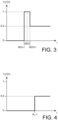
- a first implementation of the detection model is illustrated by the Figure 3 .
- any straight line 15 is considered (see figure 2 ) passing through the point of coordinates (x, y) and identified by an angle ⁇ between any two successive angles ⁇ i and ⁇ i+1 associated with detection axes 10 of the telemeter 4.
- the detection front 16 is located at a distance d( ⁇ ) less than the distance d R - ⁇ . Furthermore, at least one of the position d i of the detection horizon 9 for the angle ⁇ i and the position d i+1 of the detection horizon 9 for the angle ⁇ i+1 is strictly less than the distance d R - ⁇ .
- a second implementation of the detection model is illustrated by the Figure 4 .
- This example differs from the example in Figure 3 only in that the detection front 16 is located at a distance d( ⁇ ) greater than or equal to the distance d R - ⁇ .
- the value “0.5” reflects an unknown region, for example a region located behind an obstacle.
- a situation similar to that of the Figure 4 also occurs when, for a straight line 15 associated with an angle ⁇ between ⁇ i and ⁇ i+1 , the position d i of the detection horizon 9 for the angle ⁇ i and the position d i+1 of l
- the detection horizon 9 for the angle ⁇ i+1 are simultaneously greater than or equal to the distance d R - ⁇ .
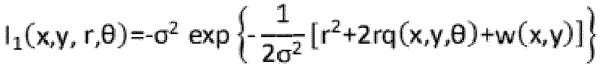
- the detection device 8 is configured to obtain each intermediate probability by an approximate calculation of relation (1).
- the detection device 8 is configured to digitally integrate, along ⁇ , the quantities I 1 (x,y,r, ⁇ ) and I 2 (x,y,r, ⁇ ) by applying, for example, the method trapezoids for each angular interval [ ⁇ i ; 0 i+1 ] and on ⁇ ( ⁇ ), so as to obtain an approximate solution for A i (x,y), B i (x,y) and C(x,y).
- any obstacle located at a distance less than the axial limit D relative to the telemeter 4, and whose transverse dimensions are greater than or equal to the distance ⁇ will appear on the obstacle presence probability map.
- the appearance of false negatives, called “empty zones”, is reduced.
- An example of an empty zone is illustrated by the figure 1 .
- the obstacles 11A and 11B are detected by the telemeter 4, but the obstacle 11C.
- the obstacle presence probability map makes the zone in which the obstacle 11C is located appear as an obstacle-free zone.
- the detection device 8 is, furthermore, configured to calculate, for any given point in space, the probability of the presence of an obstacle as a quantity proportional to a weighted sum of the intermediate probabilities corresponding, the weighting factor associated with each intermediate probability being equal to the probability of the corresponding orientation.
- the orientations ⁇ I are chosen so that, for any integer between -L and L, the quantities
- the orientations ⁇ I and ⁇ - I are symmetrical around the current orientation ⁇ ⁇ .
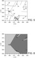
- FIG. 5 An example of a scene in which the detection system 2, on board a vehicle 20, is illustrated by the figure 5 .
- Such a scene includes other vehicles 22, pedestrians 24 and poles 26.
- the presence probability map obtained for such a scene is illustrated by the Figure 6 .
- the vehicle 20 has been represented on this presence probability map.
- the navigation device 6 determines the current position and orientation of the rangefinder 4.
- the rangefinder 4 delivers the detection signal representative of the position, along each detection axis 10, of the corresponding detection horizon.
- the detection device 8 determines, from the detection horizons 9, the position of the detection front 16.
- the detection device 8 calculates the plurality of corresponding intermediate presence probabilities.
- the detection device 8 calculates the probability of presence of obstacle at this point.
- the detection device 8 If, in a predetermined zone, the probability of the presence of an obstacle is greater than the predetermined alert threshold, the detection device 8 generates an alert.
- N c be the total number of cells in the grid
- N b the number of detection axes.
- NOT vs b the maximum number of cells crossed by a beam.
- the asymptotic complexity of the BBB process is proportional to NOT vs b NOT b .
- the value of NOT vs b is generally less than N c , so the BBB process is generally more efficient than the CBC process.
- a detection axis is likely to cross different sets of cells for each position or orientation of the telemeter, so that the same detection axis is likely to cross a cell for a given position/orientation and no longer cross it to another position/orientation.
- the asymptotic complexity of the CBC process is proportional to N c N b G 2 (2L+1) 2
- the asymptotic complexity of the BBB process is proportional to NOT vs b NOT b G 2 2 L + 1 2 .
- the complexity of calculating the probability of the presence of an obstacle at each point on the map is several orders of magnitude lower than that inherent in known methods. This results in the possibility of increasing the resolution of the map without significant detriment to calculation times.
- the detection system 2 is able to determine a three-dimensional map of the probability of presence of obstacle.
- the telemeter 4 is advantageously configured to present detection axes defining a plurality of non-merged layers.
- the navigation device 6 is configured to determine the three coordinates of the telemeter 4 in space, as well as its attitudes (pitch, yaw, roll). In this case, the uncertainty models are extended to all additional data measured by the navigation device 6.
- the detection system 2 comprises a plurality of telemeters 4.
- the detection device 8 is configured to merge the data calculated from the detection signals received from each telemeter 4 to determine the probability map of presence of obstacle.
Landscapes
- Engineering & Computer Science (AREA)
- Physics & Mathematics (AREA)
- Remote Sensing (AREA)
- Radar, Positioning & Navigation (AREA)
- General Physics & Mathematics (AREA)
- Computer Networks & Wireless Communication (AREA)
- Automation & Control Theory (AREA)
- Theoretical Computer Science (AREA)
- Electromagnetism (AREA)
- Mechanical Engineering (AREA)
- Transportation (AREA)
- Human Computer Interaction (AREA)
- Evolutionary Computation (AREA)
- Data Mining & Analysis (AREA)
- Mathematical Physics (AREA)
- Software Systems (AREA)
- Computing Systems (AREA)
- Multimedia (AREA)
- Pure & Applied Mathematics (AREA)
- Mathematical Optimization (AREA)
- Mathematical Analysis (AREA)
- General Engineering & Computer Science (AREA)
- Probability & Statistics with Applications (AREA)
- Computational Mathematics (AREA)
- Artificial Intelligence (AREA)
- Algebra (AREA)
- Acoustics & Sound (AREA)
- Radar Systems Or Details Thereof (AREA)
- Traffic Control Systems (AREA)
- Position Fixing By Use Of Radio Waves (AREA)
Claims (12)
- Computerimplementiertes Verfahren zum Detektieren von Hindernissen, dadurch gekennzeichnet, dass es für mindestens einen Entfernungsmesser (4), der eine Vielzahl von Detektionsachsen (10) aufweist, ausgehend von einer aktuellen Position des Entfernungsmessers (4), einem Unsicherheitsmodell für die Position des Entfernungsmessers (4) und einem durch den Entfernungsmesser (4) gelieferten Detektionssignal, wobei das Detektionssignal die Position eines Detektionshorizonts (9), der der Detektionsachse (10) entspricht, entlang jeder Detektionsachse (10) anzeigt, die folgenden Schritte umfasst:- Berechnen, für jeden Punkt eines Raums um den Entfernungsmesser (4) herum, ausgehend von der aktuellen Position des Entfernungsmessers (4), dem Unsicherheitsmodell für die Position des Entfernungsmessers (4) und dem Detektionssignal, einer Vielzahl von entsprechenden mittleren Anwesenheitswahrscheinlichkeiten, wobei jede mittlere Anwesenheitswahrscheinlichkeit einer jeweiligen Ausrichtung (β) des Entfernungsmessers (4) aus einer Vielzahl von vorbestimmten Ausrichtungen um eine aktuelle Ausrichtung des Entfernungsmessers zugeordnet ist, wobei jede Ausrichtung der vorbestimmten Ausrichtungen als nicht fehlerhaft angesehen wird;- Berechnen einer Wahrscheinlichkeit der Anwesenheit eines Hindernisses für jeden Punkt im Raum ausgehend von jeder entsprechenden mittleren Anwesenheitswahrscheinlichkeit und einem Unsicherheitsmodell für die Ausrichtung des Entfernungsmessers (4); und- Erzeugen einer Warnung, wenn die Wahrscheinlichkeit der Anwesenheit eines Hindernisses in einer vorbestimmten Zone in Bezug auf den Entfernungsmesser (4) größer oder gleich einer vorbestimmten Alarmschwelle ist.
- Verfahren nach Anspruch 1, wobei für einen beliebigen gegebenen Punkt im Raum die Wahrscheinlichkeit der Anwesenheit eines Hindernisses proportional zu einer gewichteten Summe der entsprechenden mittleren Wahrscheinlichkeiten ist, wobei ein mit jeder mittleren Wahrscheinlichkeit verbundener Gewichtungsfaktor gleich einer Wahrscheinlichkeit der entsprechenden Ausrichtung ist.
- Verfahren nach Anspruch 2, wobei für einen beliebigen gegebenen Punkt im Raum die Wahrscheinlichkeit der Anwesenheit eines Hindernisses gleich Folgendem ist:
 wobei P(x,y) die Wahrscheinlichkeit der Anwesenheit eines Hindernisses an dem Punkt mit den Koordinaten (x, y) ist;βI eine I. Ausrichtung des Entfernungsmessers (4) unter 2L+1 vorbestimmten Ausrichtungen um die aktuelle Ausrichtung ist;h(βI) die Wahrscheinlichkeit dafür ist, dass der Entfernungsmesser (4) die Ausrichtung βI aufweist, wenn die aktuelle Ausrichtung bekannt ist; undPβI(x,y) die mittlere Wahrscheinlichkeit der Anwesenheit an dem Punkt mit den Koordinaten (x,y) für die Ausrichtung βI des Entfernungsmessers ist.
 - Verfahren nach einem der Ansprüche 1 bis 3, wobei das Unsicherheitsmodell für die Ausrichtung des Entfernungsmessers (4) das Wahrscheinlichkeitsgesetz anwendet:

0, andernfallswobei h(β) die Wahrscheinlichkeit ist, dass der Entfernungsmesser (4) eine beliebige bestimmte Ausrichtung β aufweist;σβ eine Standardabweichung einer Messung der Ausrichtung des Entfernungsmessers (4) ist;µβ die aktuelle Ausrichtung des Entfernungsmessers (4) ist;"erf" die Fehlerfunktion ist; und"exp" die Exponentialfunktion ist. - Verfahren nach einem der Ansprüche 1 bis 4, wobei die Detektionsachsen (10) von einem gleichen Emissionspunkt (12) des Entfernungsmessers (4) stammen, wobei die Detektionsachsen (10) in einem Winkeldetektionssektor (14) enthalten sind, wobei das Verfahren das Schätzen der Position jedes Punkts einer im Winkeldetektionssektor (14) definierten Detektionsfront (16) und das Abfangen jedes Detektionshorizonts (9) umfasst.
- Verfahren nach Anspruch 5, das ein Detektionsmodell der folgenden Form implementiert:
 wobei fi(r|θ) die Wahrscheinlichkeit des Detektierens eines Hindernisses (11) in einer Entfernung r und gemäß einer Winkelkoordinate θ ist, die zwischen den Winkeln θi und θi+1 liegt, die zwei aufeinanderfolgenden Detektionsachsen (10) zugeordnet sind, wobei die Position und die Ausrichtung des Entfernungsmessers (4) nicht fehlerbehaftet sind;di bzw. di+1 die Position entlang der Detektionsachse (4) ist, die dem Winkel θi bzw. θi+1 des entsprechenden Detektionshorizonts (9) zugeordnet ist;dR die Reichweite des Entfernungsmessers (4) ist;τ die Unsicherheit bei der Messung der Position des Detektionshorizonts (9) durch den Entfernungsmesser (4) ist;"u" die Einheitsschrittfunktion ist; undd(θ) die Position der Detektionsfront (16) für die Winkelkoordinate θ ist.
 - Verfahren nach einem der Ansprüche 1 bis 6, wobei die mittlere Wahrscheinlichkeit der Anwesenheit an einem beliebigen gegebenen Punkt für eine gegebene Ausrichtung des Entfernungsmessers (4) anhand der folgenden Gleichung berechnet wird:
 wobei Pβ(x,y) die mittlere Wahrscheinlichkeit der Anwesenheit an dem Punkt mit den Koordinaten (x,y) für die Ausrichtung β des Entfernungsmessers (4) ist;F≥ der Satz aller aufeinanderfolgenden Paare von Detektionsachsen (10) ist, die den Winkeln θi bzw. θi+1 zugeordnet sind, für die die Positionen der jeweiligen Detektionshorizonte (9) di und di+1 gleichzeitig größer oder gleich dR-τ sind;F< der Satz aller aufeinanderfolgenden Paare von Detektionsachsen (10) ist, die jeweils den Winkeln θi bzw. θi+1 zugeordnet sind, für die die Position des mindestens einen der jeweiligen Detektionshorizonte (9) di und di+1 strikt kleiner als dR-τ ist;Ai(x,y) eine Menge ist, die definiert ist als:
 Bi(x,y) eine Menge ist, die definiert ist als:
 C(x,y) eine Menge ist, die definiert ist als:
 wobei:
 σ eine Standardabweichung einer Messung der Position des Entfernungsmessers ist;D eine vorbestimmte axiale Grenze ist;w(x, y) eine Größe gleich (x-µx)2 + (y-µy)2 ist;q(x, y, θ) eine Größe gleich (x-µx)cosθ + (y-µy)sinθ ist;m(x, y, θ) eine Größe gleich (x-µx)sin θ - (y-µy)cosθ ist;(µx, µy) Koordinaten sind, die die aktuelle Position des Entfernungsmessers (4) darstellen; und┌(β) ein komplementärer Winkelsektor eines Winkeldetektionssektors (14) ist, der die Detektionsachsen (10) des Entfernungsmessers (4) enthält, wobei der Entfernungsmesser (4) die Ausrichtung β aufweist.
 - Verfahren nach Anspruch 7, wobei für die axiale Grenze gilt:
 wobei ε eine gewünschte maximale Differenz zwischen zwei aufeinanderfolgenden Detektionsachsen (10) ist;Δθ der größte Winkel zwischen zwei aufeinanderfolgenden Detektionsachsen (10) ist.
 - Computerprogrammprodukt, das Programmcodebefehle umfasst, die, wenn sie von einem Computer ausgeführt werden, das Detektionsverfahren nach einem der Ansprüche 1 bis 8 implementieren.
- Vorrichtung (8) zum Detektieren von Hindernissen, die für mindestens einen Entfernungsmesser (4), der eine Vielzahl von Detektionsachsen (10) aufweist, ausgehend von einer aktuellen Position des Entfernungsmessers (4), einem Unsicherheitsmodell für die Position des Entfernungsmessers (4) und einem durch den Entfernungsmesser (4) gelieferten Detektionssignal, wobei das Detektionssignal die Position eines Detektionshorizonts (9), der der Detektionsachse (10) entspricht, entlang jeder Detektionsachse (10) anzeigt, für Folgendes konfiguriert ist:- Berechnen, für jeden Punkt eines Raums um den Entfernungsmesser (4) herum, ausgehend von der aktuellen Position des Entfernungsmessers (4), dem Unsicherheitsmodell für die Position des Entfernungsmessers (4) und dem Detektionssignal, einer Vielzahl von entsprechenden mittleren Anwesenheitswahrscheinlichkeiten, wobei jede mittlere Anwesenheitswahrscheinlichkeit einer jeweiligen Ausrichtung (β) des Entfernungsmessers (4) aus einer Vielzahl von vorbestimmten Ausrichtungen um eine aktuelle Ausrichtung des Entfernungsmessers zugeordnet ist, wobei jede der vorbestimmten Ausrichtungen als nicht fehlerhaft angesehen wird;- Berechnen einer Wahrscheinlichkeit der Anwesenheit eines Hindernisses für jeden Punkt im Raum ausgehend von jeder entsprechenden mittleren Anwesenheitswahrscheinlichkeit und einem Unsicherheitsmodell für die Ausrichtung des Entfernungsmessers (4);- Erzeugen einer Warnung, wenn die Wahrscheinlichkeit der Anwesenheit eines Hindernisses in einer vorbestimmten Zone in Bezug auf den Entfernungsmesser (4) größer oder gleich einer vorbestimmten Alarmschwelle ist.
- System (2) zum Detektieren von Hindernissen, das eine Vorrichtung (8) zum Detektieren von Hindernissen nach Anspruch 10, einen Entfernungsmesser (4) und eine Navigationsvorrichtung (6) umfasst,wobei der Entfernungsmesser (4) einer Vielzahl von Detektionsachsen (10) zugeordnet und dazu konfiguriert ist, ein Detektionssignal zu liefern, das die Position eines Detektionshorizonts (9), der der Detektionsachse (10) entspricht, entlang jeder Detektionsachse (10) anzeigt,wobei die Navigationsvorrichtung (6) dazu konfiguriert ist, die aktuelle Position und die aktuelle Ausrichtung des Entfernungsmessers (4) zu bestimmen,wobei die Detektionsvorrichtung (8) mit dem Entfernungsmesser (4) verbunden ist, um das Detektionssignal zu empfangen, und mit der Navigationsvorrichtung (6) verbunden ist, um die aktuelle Position und die aktuelle Ausrichtung des Entfernungsmessers (4) zu empfangen.
- Fahrzeug (20), das mit einem System (2) zum Detektieren von Hindernissen nach Anspruch 11 ausgestattet ist, wobei die Detektionsachsen (10) des Entfernungsmessers (4) in Richtung einer Außenseite des Fahrzeugs (20) gerichtet sind.
Applications Claiming Priority (1)
| Application Number | Priority Date | Filing Date | Title |
|---|---|---|---|
| FR1911555A FR3102253B1 (fr) | 2019-10-16 | 2019-10-16 | Procédé de détection d’obstacle, dispositif de détection, système de détection et véhicule associés |
Publications (2)
| Publication Number | Publication Date |
|---|---|
| EP3809155A1 EP3809155A1 (de) | 2021-04-21 |
| EP3809155B1 true EP3809155B1 (de) | 2024-04-03 |
Family
ID=69572097
Family Applications (1)
| Application Number | Title | Priority Date | Filing Date |
|---|---|---|---|
| EP20201670.5A Active EP3809155B1 (de) | 2019-10-16 | 2020-10-14 | Hindernis-erkennungssystem, entsprechende erkennungsvorrichtung, entsprechendes erkennungssystem und fahrzeug |
Country Status (3)
| Country | Link |
|---|---|
| US (1) | US11702092B2 (de) |
| EP (1) | EP3809155B1 (de) |
| FR (1) | FR3102253B1 (de) |
Families Citing this family (1)
| Publication number | Priority date | Publication date | Assignee | Title |
|---|---|---|---|---|
| JP7214881B2 (ja) * | 2019-09-26 | 2023-01-30 | ヤマハ発動機株式会社 | 環境地図作成装置および該方法、ならびに、自己位置推定装置、自律移動体 |
Family Cites Families (15)
| Publication number | Priority date | Publication date | Assignee | Title |
|---|---|---|---|---|
| DE102008001409A1 (de) * | 2008-04-28 | 2009-11-05 | Robert Bosch Gmbh | Verfahren zur Bestimmung von freien Bereichen in der, insbesondere für die Fahrzeugführung relevanten Umgebung eines Kraftfahrzeugs |
| DE102009045661A1 (de) * | 2009-10-14 | 2011-04-21 | Robert Bosch Gmbh | Verfahren zur Bestimmung wenigstens eines befahrbaren Bereichs in der, insbesondere für die Fahrzeugführung relevanten Umgebung eines Kraftfahrzeugs |
| US20160112061A1 (en) | 2014-10-21 | 2016-04-21 | International Business Machines Corporation | Non-recursive cascading reduction |
| US10630410B2 (en) * | 2016-05-13 | 2020-04-21 | Telefonaktiebolaget Lm Ericsson (Publ) | Network architecture, methods, and devices for a wireless communications network |
| US10175059B2 (en) * | 2016-08-30 | 2019-01-08 | Here Global B.V. | Method, apparatus and computer program product for a navigation system user interface |
| CN117310741A (zh) * | 2017-01-03 | 2023-12-29 | 应诺维思科技有限公司 | 用于检测和分类物体的激光雷达系统和方法 |
| FR3072180B1 (fr) | 2017-10-06 | 2019-11-01 | Commissariat A L'energie Atomique Et Aux Energies Alternatives | Procede de localisation d'une borne d'acces a un reseau de communication |
| FR3077877B1 (fr) | 2018-02-14 | 2020-03-13 | Commissariat A L'energie Atomique Et Aux Energies Alternatives | Procede de calibration d'un capteur tri-axe avec selection d'une methode de calibration en fonction de la distribution spatiale des mesures |
| FR3079295B1 (fr) | 2018-03-21 | 2020-09-25 | Commissariat Energie Atomique | Procede de detection de pics d'acceleration a echantillonnage non-uniforme |
| FR3093493B1 (fr) | 2019-03-04 | 2021-04-09 | Commissariat Energie Atomique | Procédé de détection d’anomalie de matériel roulant exploitant un signal de déformation d’un support de rail |
| CN113795773A (zh) * | 2019-03-08 | 2021-12-14 | 欧司朗股份有限公司 | 用于lidar传感器系统的部件,lidar传感器系统,lidar传感器装置,用于lidar传感器系统的方法和用于lidar传感器装置的方法 |
| CN111272165B (zh) * | 2020-02-27 | 2020-10-30 | 清华大学 | 一种基于特征点标定的智能车定位方法 |
| US11801867B2 (en) * | 2020-03-30 | 2023-10-31 | Honda Motor Co., Ltd. | Vehicle control device and vehicle control method |
| US20210339741A1 (en) * | 2020-04-30 | 2021-11-04 | Zoox, Inc. | Constraining vehicle operation based on uncertainty in perception and/or prediction |
| FR3114174A1 (fr) * | 2020-09-14 | 2022-03-18 | Commissariat A L'energie Atomique Et Aux Energies Alternatives | Procédé et système de détection coopérative de corps matériels dans un environnement |
-
2019
- 2019-10-16 FR FR1911555A patent/FR3102253B1/fr active Active
-
2020
- 2020-10-14 US US17/070,558 patent/US11702092B2/en active Active
- 2020-10-14 EP EP20201670.5A patent/EP3809155B1/de active Active
Also Published As
| Publication number | Publication date |
|---|---|
| FR3102253A1 (fr) | 2021-04-23 |
| FR3102253B1 (fr) | 2022-01-14 |
| US11702092B2 (en) | 2023-07-18 |
| US20210114612A1 (en) | 2021-04-22 |
| EP3809155A1 (de) | 2021-04-21 |
Similar Documents
| Publication | Publication Date | Title |
|---|---|---|
| EP2598912B1 (de) | Verfahren zur bestimmung eines schutzraums im falle von zwei gleichzeitigen satellitenausfällen | |
| CN109435955B (zh) | 一种自动驾驶系统性能评估方法、装置、设备及存储介质 | |
| EP3364213B1 (de) | Verfahren und system der kontextualiserten wahrnehmung von materiellen körpern | |
| CA2171789A1 (fr) | Dispositif d'evitement de collisions pour aeronef notamment avec le sol | |
| RU2757038C2 (ru) | Способ и система для предсказания будущего события в беспилотном автомобиле (sdc) | |
| WO2016034516A2 (fr) | Dispositif et procédé de localisation et de cartographie | |
| EP3809155B1 (de) | Hindernis-erkennungssystem, entsprechende erkennungsvorrichtung, entsprechendes erkennungssystem und fahrzeug | |
| EP3968219A1 (de) | Verfahren und system zur kooperativen detektion von materiellen körpern in einer umgebung | |
| EP1205732B1 (de) | Inertialnavigationseinheit mit integriertem GPS-Empfänger | |
| EP3485292B1 (de) | Verfahren und vorrichtung zur bestimmung einer geografischen, operationalen, durch einen sensor beobachteten zone | |
| EP2366094B1 (de) | Verfahren mit druckhöhenkorrektur für ein flugzeug | |
| EP2804016A1 (de) | Verbessertes Verfahren zur Bestimmung der Position und/oder Geschwindigkeit eines gesteuerten Fahrzeugs, sowie entsprechendes System | |
| EP3472015B1 (de) | Verfahren zur bestimmung einer referenzfahrklasse | |
| WO2009101139A1 (fr) | Procede de localisation radioelectrique en trois dimensions en fonctionnement multistatique | |
| EP1331621B1 (de) | Verfahren zum Überwachen des Umfeldes eines Fahrzeugs | |
| WO2021032749A1 (fr) | Detection d'une operation de leurrage d'un recepteur de signaux satellitaires | |
| WO2016146823A1 (fr) | Procédé d'estimation de paramètres géométriques représentatifs de la forme d'une route, système d'estimation de tels paramètres et véhicule automobile équipé d'un tel système | |
| FR2820215A1 (fr) | Procede de detection d'obstacles par un systeme radar et procede de caracterisation d'un obstacle detecte par ce procede | |
| WO2021228618A1 (fr) | Methode et systeme de generation d'une carte de probabilite, pour un porteur, d'etre localise par un reseau de capteurs de localisation | |
| WO2023061915A1 (fr) | Procédé de détection d'une limite d'une voie de circulation | |
| Meredith et al. | Efficient collocation of global navigation satellite system radio occultation soundings with passive nadir microwave soundings | |
| WO2020254216A1 (fr) | Procédé de surveillance de l'environnement d'un véhicule | |
| EP4150363A1 (de) | Verfahren und system zur erzeugung einer wahrscheinlichkeitskarte, für einen träger, der von einem detektionssystem erkannt wird | |
| WO2023180143A1 (fr) | Procédé de détermination d'au moins un rayon de protection associé a au moins un parametre de navigation et dispositif électronique de détermination associé | |
| WO2021228617A1 (fr) | Methode et systeme de generation d'une carte de probabilite de presence d'un emetteur |
Legal Events
| Date | Code | Title | Description |
|---|---|---|---|
| PUAI | Public reference made under article 153(3) epc to a published international application that has entered the european phase |
Free format text: ORIGINAL CODE: 0009012 |
|
| STAA | Information on the status of an ep patent application or granted ep patent |
Free format text: STATUS: EXAMINATION IS IN PROGRESS |
|
| 17P | Request for examination filed |
Effective date: 20201014 |
|
| AK | Designated contracting states |
Kind code of ref document: A1 Designated state(s): AL AT BE BG CH CY CZ DE DK EE ES FI FR GB GR HR HU IE IS IT LI LT LU LV MC MK MT NL NO PL PT RO RS SE SI SK SM TR |
|
| AX | Request for extension of the european patent |
Extension state: BA ME |
|
| GRAP | Despatch of communication of intention to grant a patent |
Free format text: ORIGINAL CODE: EPIDOSNIGR1 |
|
| STAA | Information on the status of an ep patent application or granted ep patent |
Free format text: STATUS: GRANT OF PATENT IS INTENDED |
|
| RIC1 | Information provided on ipc code assigned before grant |
Ipc: G01S 15/89 20060101ALI20230922BHEP Ipc: G01S 13/89 20060101ALI20230922BHEP Ipc: G01S 7/53 20060101ALI20230922BHEP Ipc: G01S 7/295 20060101ALI20230922BHEP Ipc: G01S 15/931 20200101ALI20230922BHEP Ipc: G01S 17/931 20200101ALI20230922BHEP Ipc: G01S 17/89 20200101ALI20230922BHEP Ipc: G01S 13/931 20200101ALI20230922BHEP Ipc: G01S 7/48 20060101AFI20230922BHEP |
|
| INTG | Intention to grant announced |
Effective date: 20231025 |
|
| GRAS | Grant fee paid |
Free format text: ORIGINAL CODE: EPIDOSNIGR3 |
|
| GRAA | (expected) grant |
Free format text: ORIGINAL CODE: 0009210 |
|
| STAA | Information on the status of an ep patent application or granted ep patent |
Free format text: STATUS: THE PATENT HAS BEEN GRANTED |
|
| AK | Designated contracting states |
Kind code of ref document: B1 Designated state(s): AL AT BE BG CH CY CZ DE DK EE ES FI FR GB GR HR HU IE IS IT LI LT LU LV MC MK MT NL NO PL PT RO RS SE SI SK SM TR |
|
| REG | Reference to a national code |
Ref country code: CH Ref legal event code: EP |
|
| REG | Reference to a national code |
Ref country code: IE Ref legal event code: FG4D Free format text: LANGUAGE OF EP DOCUMENT: FRENCH |
|
| REG | Reference to a national code |
Ref country code: DE Ref legal event code: R096 Ref document number: 602020028233 Country of ref document: DE |