EP3809078A1 - Haushaltskältegerätevorrichtung - Google Patents
Haushaltskältegerätevorrichtung Download PDFInfo
- Publication number
- EP3809078A1 EP3809078A1 EP20199784.8A EP20199784A EP3809078A1 EP 3809078 A1 EP3809078 A1 EP 3809078A1 EP 20199784 A EP20199784 A EP 20199784A EP 3809078 A1 EP3809078 A1 EP 3809078A1
- Authority
- EP
- European Patent Office
- Prior art keywords
- material layer
- valve element
- advantageously
- operating state
- unit
- Prior art date
- Legal status (The legal status is an assumption and is not a legal conclusion. Google has not performed a legal analysis and makes no representation as to the accuracy of the status listed.)
- Granted
Links
Images


Classifications
-
- F—MECHANICAL ENGINEERING; LIGHTING; HEATING; WEAPONS; BLASTING
- F25—REFRIGERATION OR COOLING; COMBINED HEATING AND REFRIGERATION SYSTEMS; HEAT PUMP SYSTEMS; MANUFACTURE OR STORAGE OF ICE; LIQUEFACTION SOLIDIFICATION OF GASES
- F25D—REFRIGERATORS; COLD ROOMS; ICE-BOXES; COOLING OR FREEZING APPARATUS NOT OTHERWISE PROVIDED FOR
- F25D23/00—General constructional features
- F25D23/06—Walls
- F25D23/062—Walls defining a cabinet
- F25D23/064—Walls defining a cabinet formed by moulding, e.g. moulding in situ
-
- F—MECHANICAL ENGINEERING; LIGHTING; HEATING; WEAPONS; BLASTING
- F25—REFRIGERATION OR COOLING; COMBINED HEATING AND REFRIGERATION SYSTEMS; HEAT PUMP SYSTEMS; MANUFACTURE OR STORAGE OF ICE; LIQUEFACTION SOLIDIFICATION OF GASES
- F25D—REFRIGERATORS; COLD ROOMS; ICE-BOXES; COOLING OR FREEZING APPARATUS NOT OTHERWISE PROVIDED FOR
- F25D2201/00—Insulation
- F25D2201/10—Insulation with respect to heat
- F25D2201/12—Insulation with respect to heat using an insulating packing material
- F25D2201/126—Insulation with respect to heat using an insulating packing material of cellular type
-
- Y—GENERAL TAGGING OF NEW TECHNOLOGICAL DEVELOPMENTS; GENERAL TAGGING OF CROSS-SECTIONAL TECHNOLOGIES SPANNING OVER SEVERAL SECTIONS OF THE IPC; TECHNICAL SUBJECTS COVERED BY FORMER USPC CROSS-REFERENCE ART COLLECTIONS [XRACs] AND DIGESTS
- Y02—TECHNOLOGIES OR APPLICATIONS FOR MITIGATION OR ADAPTATION AGAINST CLIMATE CHANGE
- Y02B—CLIMATE CHANGE MITIGATION TECHNOLOGIES RELATED TO BUILDINGS, e.g. HOUSING, HOUSE APPLIANCES OR RELATED END-USER APPLICATIONS
- Y02B40/00—Technologies aiming at improving the efficiency of home appliances, e.g. induction cooking or efficient technologies for refrigerators, freezers or dish washers
Definitions
- the invention relates to a household refrigerator device according to the preamble of claim 1 and a method for producing a household refrigerator device according to the preamble of claim 14.
- a household refrigerator with a household refrigerator device which has a body is already known from the prior art.
- the body is a device body and, in an operating state, delimits an insulation space together with a device door body.
- the device body has a filling opening for filling insulation material into the insulation space.
- the household refrigeration appliance device has a valve unit with a valve element which, at least before the insulation material is filled in, is mounted on the body so that it can move in sections relative to the body.
- the valve element is provided for closing the filling opening.
- the valve element consists of a single layer of material.
- the object of the invention is in particular, but not limited to, to advantageously further develop a device of the generic type.
- the object is achieved according to the invention by the features of claims 1 and 14, while advantageous configurations and developments of the invention can be found in the subclaims.
- the invention is based on a household refrigerator device with at least one body which at least partially delimits at least one insulation space and which has at least one filling opening for filling insulation material into the insulation space, and with at least one valve unit which has at least one valve element.
- the valve element can be mounted on the body so as to be movable at least in sections relative to the body, in particular on a side facing the insulation space, and in particular before the insulation material is filled.
- valve element have at least one first material layer and at least one second material layer different from the first material layer.
- a device of the generic type in particular can advantageously be further developed by means of such a configuration.
- a particularly high level of flexibility can be achieved since, for example, different materials can be selected for the material layer and / or different thicknesses of the material layers.
- different materials with different thicknesses and / or with different material properties could be selected for the material layers.
- at least one material layer could be provided as a sealing layer and at least one further material layer could be provided as a flame retardant layer.
- a simple adaptability to new standard requirements can be made possible, such as, for example, to new fire protection regulations and / or to new flame protection regulations.
- a particularly stable valve element can be provided, which has particularly low deformations, in particular under the influence of foaming pressure, which could be caused in particular by insulation material located in the insulation space, whereby in particular foaming and / or leakage of insulation material from the inlet opening can be specifically and / or optimally prevented.
- a “household refrigerator device” is to be understood as meaning in particular at least a part, in particular a subassembly, of a household refrigerator, in particular before it is filled and / or foamed with insulation material.
- a household refrigerator is particularly advantageously provided to cool goods to be cooled, in particular food such as drinks, meat, fish, milk and / or dairy products, in an operating state, in particular in order to bring about a longer shelf life of the goods to be cooled.
- the household refrigerator can in particular be a freezer and / or a freezer.
- the household refrigerator can advantageously be a refrigerator and / or freezer.
- a “body” is to be understood as meaning, in particular, a unit which at least partially delimits the isolation space and, in particular, in addition to the isolation space, in particular at least one cold space, and which in particular in an operating state has a part, in particular a large part, a outer boundary, in particular a housing, advantageously a household refrigerator housing, is formed.
- an object delimits a space “at least partially” should be understood in particular to mean that the object delimits the space alone and / or that the object delimits the space together with at least one further unit.
- the body delimits the isolation space at least to a large extent.
- the body could limit the isolation space on its own.
- the body advantageously delimits the insulation space together with at least one further unit, such as, for example, together with the valve unit.
- the body could for example define and / or limit at least one cold room at least partially and advantageously at least to a large extent.
- the body could delimit the cold room together with at least one further body.
- the body could, for example, be a device body and the further body a device door body.
- the body could, for example, be a device door body and the further body could be a device body.
- the cold room is provided in particular for storing and / or keeping at least one food item, in particular for the purpose of cooling the food item.
- At least to a large extent should be understood to mean in particular a proportion, in particular a mass proportion and / or a volume proportion, of at least 70%, in particular of at least 80%, advantageously of at least 90% and preferably of at least 95%.
- An "operating state” is to be understood in particular as a state in which the appliance door, in particular the appliance door body of the appliance door, is in a closed state and rests against the body, whereby the body and the appliance door, in particular the appliance door body of the appliance door, form the cold room in particular limit at least to a large extent and advantageously, in particular completely, limit.
- food arranged in the cold room is properly cooled in an operating state.
- the household refrigerator device has in particular at least one device body.
- the device body defines and / or delimits in particular at least one cold room, in particular at least partially and advantageously at least to a large extent.
- a "device body” is to be understood in particular as a unit which, in an operating state, forms a part, in particular a large part, of an outer boundary, in particular a housing, advantageously of a household refrigerator housing, and which, in an operating state, forms a part, in particular a large part, of an outer boundary Delimitation of at least one cold room, in particular a cold room and / or a freezer room, is defined and / or limited.
- the device body delimits the cold room in an operating state, in particular together with at least one device door body, at least to a large extent and advantageously completely.
- the device body has at least one side wall, in particular at least two side walls, and / or at least one rear wall and / or at least one top wall and / or at least one bottom wall, which together with the device door body enclose the cold room in an operating state.
- the domestic refrigeration appliance device has at least one appliance door, which in particular has at least one appliance door body.
- a “device door body” should be understood to mean, in particular, a unit which, in an operating state, is movably and in particular pivotably connected to the device body relative to the device body and which, in an operating state, forms part of an outer boundary, in particular a housing, advantageously a household refrigerator housing .
- the device body and the device door body advantageously jointly form the outer boundary, in particular the housing, advantageously the household refrigerator housing.
- the body could be a device body and in particular be designed in one piece and / or identical to the device body.
- the body which could in particular be a device body, could, for example, in an operating state, form at least a large part of the outer boundary, in particular of a housing, advantageously of a household refrigerator housing.
- the body could for example be an appliance door body and in particular in one piece and / or identical to that Be designed appliance door body.
- the body which could in particular be an appliance door body, could, for example, in an operating state, at least partially form the outer boundary, in particular of a housing, advantageously of a household refrigerator housing.
- insulation space is to be understood in particular as a spatial area which is provided for filling and / or storing insulation material, in particular for the purpose of thermal insulation of at least one cold space at least partially delimited by the body.
- the insulation space is in particular at least to a large extent and advantageously completely filled with insulation material, in particular for the purpose of thermal insulation of at least one cold room which is at least partially delimited by the body.
- the body could have at least two, in particular at least three, advantageously at least four and preferably several isolation spaces, which in particular could be arranged at least partially adjacent to one another and which could in particular extend over one, in particular the entire, extent of the body.
- the body advantageously has, in particular precisely, one, advantageously single, insulation space which extends in particular over one, in particular the entire, extent of the body.
- a “filling opening” is to be understood in particular as an opening which is provided in particular for introducing at least one filling tool and for filling in insulation material.
- the filling opening receives at least part of the filling tool when insulating material is being filled.
- An “opening” is to be understood as meaning, in particular, a recess and / or a cutout.
- the body in particular per isolation space, could have in particular at least two, advantageously at least three, particularly advantageously at least four, preferably at least five and particularly preferably several filling openings.
- the body has, in particular for each insulation space, in particular at least one and advantageously exactly one filling opening.
- valve unit is to be understood in particular as a unit which, in particular by means of the valve element, for at least partial opening of the filling opening, in particular for the purpose of filling insulation material into the Isolation space, and / or for closing the filling opening, in particular for the purpose of preventing insulation material from escaping from the isolation space, is provided.
- the valve element could, for example, be arranged on a side of the body facing away from the insulation space, and in particular additionally the cold space.
- the valve element is advantageously arranged on a side of the body facing the insulation space, and in particular also on a side of the body facing away from the cold room, whereby in particular easy accessibility of the valve element and / or simple filling of insulation material into the insulation space can be achieved.
- valve element is mounted movably relative to the body on the body "at least in sections" should be understood in particular to mean that the valve element has at least one portion which is movably mounted on the body relative to the body, and in particular additionally to the section could have at least one section which is immovably mounted on the body relative to the body.
- the section and the further section could in particular be located on opposite end regions of the valve element.
- the valve element could advantageously be fastened to the body by means of the further section.
- the body and / or the valve element could, for example, be provided for production by means of plate cutting and in particular be produced by means of plate cutting, whereby particularly low costs and / or simple production could be achieved in particular.
- a second material layer "different" from the first material layer is to be understood in particular to mean that the two material layers are different components and / or bodies which are coupled to one another in particular in an operating state.
- At least one of the material layers, and advantageously the material layers has an in particular at least substantially constant and advantageously constant density over an extension of the corresponding material layer.
- At least one of the material layers and advantageously the material layers consists in particular of one Expansion of the corresponding material layer away from the same material and / or from the same materials.
- At least one of the material layers, and advantageously the material layers is designed in particular planar and has in particular a planar shape.
- at least one of the material layers and advantageously the material layers has a thickness which is significantly smaller than a longitudinal extension of the corresponding material layer and / or than a transverse extension of the corresponding material layer.
- the longitudinal extension of a material layer and / or the transverse extension of a material layer has, for example, a value of at least 1.5 times, in particular at least 2 times, advantageously at least 5 times, particularly advantageously at least 10 times, preferably at least 15 times. times and particularly preferably at least 20 times a value of the thickness of the corresponding material layer.
- the phrase “at least one of the material layers” is intended to mean in particular the first material layer and / or the second material layer.
- a “longitudinal extension” of an object is to be understood as meaning, in particular, a length of a longest side of a smallest imaginary geometric cuboid which just completely encloses the object.
- a “transverse extension” of an object is to be understood as meaning, in particular, a length of a second longest side of a smallest imaginary geometric cuboid which just completely encloses the object.
- a “thickness” of an object is to be understood as meaning, in particular, a length of a shortest side of a smallest imaginary geometric cuboid which just completely encloses the object.
- the thickness and the longitudinal extent are aligned perpendicular to one another.
- the transverse extent and the thickness are in particular aligned perpendicular to one another.
- the transverse extent and the longitudinal extent are aligned perpendicular to one another.
- Provided is to be understood in particular as specifically designed and / or equipped.
- the fact that an object is provided for a specific function is to be understood in particular to mean that the object fulfills and / or executes this specific function in at least one application and / or operating state.
- first material layer and the second material layer are connected to one another.
- first material layer and the second The material layer can be connected to one another at at least two, in particular at least three, advantageously at at least five, particularly advantageously at at least ten, preferably at at least fifteen and particularly preferably at a plurality of points.
- the first material layer and the second material layer are preferably connected to one another over a large area.
- the valve element has at least one connecting unit which connects the first material layer and the second material layer to one another.
- the connection unit in particular produces a mechanical connection between the first material layer and the second material layer and in particular brings about a coupling between the first material layer and the second material layer. As a result, a compact and / or stable configuration can in particular be provided.
- first material layer and the second material layer could be connected to one another in a force-locking and / or form-locking manner.
- the connecting unit could connect the first material layer and the second material layer to one another, in particular in a force-locking and / or form-locking manner.
- the first material layer and the second material layer are preferably materially connected to one another.
- the connection unit connects the first material layer and the second material layer to one another, in particular in a materially bonded manner.
- Two objects that are "cohesively" connected to one another are to be understood as meaning, in particular, two objects which are glued to one another and / or injected onto one another and / or coextruded and / or connected to one another by a two-component injection molding process.
- the first material layer and the second material layer are particularly advantageously connected to one another by means of double-sided adhesive tape.
- the connecting unit has in particular at least one double-sided adhesive tape and in particular connects the first material layer and the second material layer to one another by means of the double-sided adhesive tape. In this way, particularly high stability can be achieved in particular. In particular, simple and / or inexpensive manufacture can be achieved.
- first material layer and the second material layer are designed to be at least substantially geometrically identical, and in particular geometrically identical.
- the phrase that the first material layer and the second material layer are "geometrically identical" is intended in particular it is understood that the first material layer and the second material layer have the same and / or identical geometric properties.
- the geometric property could be a surface extension and / or a longitudinal extension and / or a transverse extension and / or a thickness.
- the first material layer and the second material layer could, for example, have at least essentially identical surface extensions and / or at least essentially identical thicknesses.
- first material layer and the second material layer are "at least substantially" geometrically identical should be understood in particular to mean that the first material layer has a first value with respect to a specific geometric property and the second material layer has a specific value geometric property have a second value, of which a quotient of a smaller of the values and a larger of the values at least 0.5, in particular at least 0.7, advantageously at least 0.8, particularly advantageously at least 0.9, preferably at least 0.95 and particularly preferably at least 0.98.
- an optimized valve element can be provided which in particular optimally seals the filling opening in an operating state and / or which in particular is easy to handle and / or simple to manufacture.
- the first material layer and the second material layer could in particular consist at least partially and advantageously at least to a large extent from the same and / or from identical material.
- the first material layer and the second material layer preferably consist at least to a large extent of different materials.
- at least one of the material layers could be made at least to a large extent from at least one softer material than at least one other of the material layers, whereby in particular an optimized sealing of the filling opening could be achieved.
- a particularly high degree of flexibility and / or a particularly high degree of design freedom can thereby be achieved.
- an optimized valve element and / or adapted to certain conditions can be provided, whereby an optimal sealing of the filler opening can be ensured in particular independently of certain conditions and / or certain configurations.
- At least one of the material layers consists at least for the most part of at least one plastic.
- the first material layer could consist at least to a large extent of at least one first plastic and the second material layer could consist at least to a large extent of at least one second plastic different from the first plastic.
- the plastic could, for example, be at least one polymer and / or at least one thermoplastic, such as polystyrene, for example. In this way, in particular, a cost-effective design can be achieved.
- At least one of the material layers consists at least for the most part of at least one flame retardant material.
- the first material layer could consist at least to a large extent of at least one first flame retardant material and the second material layer could consist at least to a large extent of at least one second flame retardant material different from the first flame retardant material.
- the flame retardant material could, for example, be at least one plastic that is classified as flame retardant.
- the flame retardant material could be a material that is used in fiberglass mats and / or fire protection mats and / or fire blankets.
- the flame retardant material could, for example, be at least one glass fiber mat and / or at least one fire protection mat and / or at least one Act fire blanket. In this way, in particular, common standard requirements can be met and / or a particularly low risk of fire can be achieved.
- At least one of the material layers could consist of at least a large part of at least one flexible material and at least one other of the material layer could consist of at least a large part of at least one flame retardant material, whereby in particular a particularly advantageous and / or optimized valve element could be provided.
- the valve element could, for example, have at least one material layer designed as a sealing layer and at least one material layer designed as a flame retardant layer, whereby in particular a valve element that is optimally adapted to all requirements could be provided.
- At least one of the material layers and in particular the material layers could, for example, advantageously each have a thickness of a maximum of 5 mm, in particular of a maximum of 4 mm, advantageously of a maximum of 3.5 mm, particularly advantageously of a maximum of 3 mm, preferably of a maximum of 2.5 mm and particularly preferably have a maximum of 2 mm.
- At least one of the material layers and in particular the material layers, advantageously each, have a thickness of a maximum of 0.9 mm, in particular of a maximum of 0.8 mm, advantageously of a maximum of 0.7 mm, particularly advantageously of a maximum of 0.6 mm , preferably of a maximum of 0.55 mm and particularly preferably of a maximum of 0.5 mm.
- at least one of the material layers and in particular the material layers, advantageously each has a thickness of at least 0.001 mm, in particular of at least 0.01 mm, advantageously of at least 0.05 mm, particularly advantageously of at least 0.1 mm, preferably of at least 0 , 2 mm and particularly preferably of at least 0.3 mm.
- valve element is easy to bend on the one hand and, on the other hand, particularly advantageously automatically moves towards a rest position of the valve element.
- the valve element especially starting from the operating position of the valve element, tends to move particularly quickly to the rest position of the valve element, which in particular enables the filling opening to be sealed particularly quickly.
- valve element following a deflection of the valve element from a rest position of the valve element into an operating position of the valve element, the valve element automatically strives back into the rest position of the valve element. In this way, particularly simple introduction of insulation material into the insulation space can be made possible, whereby in particular time-saving and / or inexpensive and / or simple manufacture can be made possible.
- the household refrigeration appliance device could, for example, have at least one fastening unit which, in an operating state, releasably connects the valve element to the body, for example releasably without tools, and in particular connects it to the body.
- a "releasable" connection should in particular be a connection that can be released without tools and / or a non-destructive connection using tools releasable connection are understood.
- the fastening unit could, for example, connect the valve element to the body in a force-fitting and / or form-fitting manner.
- the fastening unit could the valve element in an operating state by means of at least one latching connection and / or by means of at least one clamping connection and / or by means of at least one plug connection and / or by means of at least one connection caused by locking and / or by means of at least one connection caused by pushing in and / or connect to the body by means of at least one connection brought about by buttonholes.
- the household refrigerator device preferably has at least one fastening unit which, in an operating state, firmly connects the valve element to the body and, in particular, connects it to the body.
- a "fixed” connection should be understood to mean, in particular, a connection that can be released nondestructively exclusively by using a tool and / or a connection exclusively through destruction and / or damage to at least one component involved in the connection, such as in particular the valve element and / or the body. In this way, a high level of stability can in particular be achieved. In particular, an unintentional detachment of the valve element from the body can be avoided, as a result of which, in particular, a durable and / or functional design can be provided.
- the household refrigerator device has at least one and in particular at least the fastening unit which, in an operating state, connects the valve element to the body on one side and, in particular, connects it to the body.
- the fastening unit connects in particular at least one and advantageously the section of the valve element to the body and in particular leaves at least one further and advantageously the further section of the valve element unconnected to the body.
- the section is arranged, in particular, in at least one end region of the valve element and in particular forms the end region of the valve element.
- the further section is arranged in particular in at least one further end region of the valve element opposite the end region and in particular forms the further end region of the valve element.
- the fastening unit could connect the valve element to the body, for example via at least one joint.
- the joint could, for example, be part of the fastening unit.
- the joint and the valve element could be different from one another.
- the joint could be formed, for example, by the valve element.
- the domestic refrigeration appliance device preferably has at least one and in particular at least the fastening unit which, in an operating state, connects the valve element to the body without joints and, in particular, connects it to the body.
- a “joint-free” connection is to be understood in particular as a connection avoiding joints and / or a connection which is free of joints.
- the valve element can be connected to the body in particular by means of a connection which has a particularly low probability of damage and / or a defect, as a result of which, in particular, a long-lasting design can be achieved.
- the body be a device body and in particular be designed as a device body.
- the body has at least one and advantageously at least the device body.
- a particularly efficient device body can be provided, the insulation space of which can be filled with insulation material in a simple manner and / or particularly effectively protected against the escape of insulation material from the inlet opening.
- the body in particular in addition to the device body, could have at least one and advantageously at least the device door body.
- the body is preferably designed as an appliance door body and in particular as an appliance door body.
- an optimally insulated appliance door can thereby be provided.
- a particularly optimized and / or advantageous embodiment can in particular be achieved by a household refrigerator with at least one household refrigerator device according to the invention, which is in particular filled with foam.
- foam is to be understood here as meaning that the insulation space is partially or completely filled with insulation material, for example polyurethane foam.
- a particularly simple and / or uncomplicated and / or inexpensive production can in particular be achieved by a method for producing a household refrigerator device according to the invention with at least one body which at least partially delimits at least one insulation space and which at least one filling opening for filling insulation material into the insulation space and with at least one valve unit which has at least one valve element which is at least partially movably mounted on the body relative to the body, the valve element having at least one first material layer and at least one second material layer different from the first material layer, which are connected to one another become.
- the household refrigerator device should not be restricted to the application and embodiment described above.
- the household refrigeration appliance device can have a number of individual elements, components and units that differs from a number of individual elements, components and units mentioned herein in order to fulfill a mode of operation described herein.
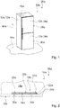
- FIG 1 shows, by way of example, a household refrigeration appliance 36a which has a household refrigeration appliance device 10a.
- the household refrigerator 36a could be designed as a freezer and / or as a freezer and / or as a combination fridge-freezer.
- the household refrigerator 36a is designed in particular as a refrigerator and as a freezer, in particular as a combination refrigerator-freezer.
- the household refrigerator device 10a has in particular at least one and advantageously exactly one device body 32a.
- the device body 32a defines in particular at least partially a cold room (not shown).
- the cold room is designed in particular as a cooling room.
- the household refrigeration appliance device 10a has at least one and advantageously exactly one appliance door 38a.
- the appliance door 38a is in particular mounted so as to be pivotable relative to the appliance body 32a.
- the appliance door 18a closes in particular the cold room.
- the device body 16a in particular at least partially defines a further cold room (not shown).
- the further cold room is designed in particular as a freezer room.
- the household refrigeration appliance device 10a has at least one and advantageously exactly one further appliance door 40a.
- the further appliance door 40a is in particular mounted so as to be pivotable relative to the appliance body 32a. In a closed state of the further appliance door 40a, the further appliance door 40a closes, in particular, the further cold room.
- the further cold room is arranged in an installation position, in particular with respect to a vertical direction 42a, below the cold room.
- the device body 32a is set up in particular on a set-up surface 44a.
- the installation area could be formed by at least one floor and / or by at least one floor and / or by at least one subsurface.
- the installation surface 44a is formed in particular by a floor, in particular of a room, advantageously of a house.
- the vertical direction 42a is in particular aligned at least substantially perpendicularly and advantageously perpendicularly to the installation surface 44a.
- the appliance door 38a and the further appliance door 40a are in particular constructed at least essentially identical and / or analogous to one another. Therefore, in the following, only the appliance door 38a is described as an example of the appliance door 38a and the further appliance door 40a.
- the appliance door 38a has in particular at least one and advantageously exactly one appliance door body 34a.
- the appliance door body 34a defines in particular an outer one Shape and / or shape of the appliance door 38a at least to a large extent.
- the appliance door body 34a forms at least a large part of an external shape and / or shape of the appliance door 38a.
- the household refrigerator device 10a has in particular at least one and advantageously exactly one control unit 46a.
- the control unit 46a controls and / or regulates in particular at least one device function and / or at least one main device function, in particular of the household device 36a.
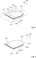
- the household refrigerator device 10a has in particular at least one body 12a (cf. Figures 1 to 3 ).
- the body 12a could, for example, be an appliance door body 34a and in particular be designed as an appliance door body 34a.
- the body 12a and the appliance door body 34a, in particular the appliance door 38a could be identical.
- the body 12a could, in particular alternatively or additionally, for example be a device body 32a and in particular be designed as a device body 32a.
- the body 12a and the device body 32a could be identical.
- a description of the body 12a is identical regardless of whether the body 12a is a device door body 34a or a device body 32a. Therefore, in the following, only the body 12a is described by way of example, specifically as a representative of both a body 12a, which is a device door body 34a, and for a body 12a, which is a device body 32a.
- the body 12a delimits at least one insulation space 14a, in particular at least partially and advantageously at least to a large extent (cf. Figure 2 ).
- the body 12a delimits the insulation space 14a in an operating state together with at least one valve unit 18a, in particular completely.
- the body 12a has in particular at least one filling opening 16a for filling insulation material into the insulation space 14a (cf. Figures 2 and 3 ).
- the filling opening 16a is provided in particular for inserting a filling tool 48a.
- the filling opening 16a is provided for filling insulation material into the insulation space 14a, advantageously by means of the filling tool 48a.
- the insulation material is designed in particular foam-like and / or as a foam.
- the insulation material could be polyurethane, which in particular is abbreviated as PUR.
- PUR polyurethane
- the filling of insulation material into the insulation space 14a could be carried out by means of at least one foaming system, which could differ in particular depending on the given circumstances, such as for example a design and / or a type of the domestic refrigerator 36a.
- the household refrigerator device 10a has in particular at least one and advantageously exactly one valve unit 18a, in particular at least and advantageously precisely the valve unit 18a (cf. Figures 2 to 6 ).
- the valve unit 18a has in particular at least one and advantageously precisely one valve element 20a.
- the valve element 20a is connected in particular to the body 12a.
- the valve element 20a is mounted on the body 12a so that it can move at least in sections relative to the body 12a.
- the valve element 20a has in particular at least one and advantageously exactly one section 50a which is mounted immovably relative to the body 12a and in particular is connected to the body 12a.
- the valve element 20a has in particular at least one and advantageously exactly one further section 52a, which is movably mounted relative to the body 12a.
- the valve element 20a is advantageously connected to the body 12a on the foam side and is advantageously fastened to the body 12a.
- the valve element 20a is connected to the body 12a in particular on a side facing the insulation space 14a and is advantageously fastened to the body 12a.
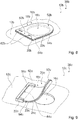
- the household refrigerator device 10a for fastening the valve element 20a to the body 12a, has in particular at least one and advantageously exactly one fastening unit 30a (cf. Figures 3 to 6 ).
- the fastening unit 30a fastens the valve element, in particular, to the body 12a, in particular on the foam side.
- the fastening unit 30a is in particular arranged at least for the most part within the insulation space 14a.
- the fastening unit 30a connects the valve element 20a, in particular on one side, to the body 12a.
- the fastening unit fastens the valve element 20a on one side of the body 12a in an operating state.
- the fastening unit 30a connects in particular the section 50a of the valve element 20a to the body 12a and in particular allows the further section 52a of the valve element 20a to be movable relative to the body 12a.
- the fastening unit 30a acts in particular directly on the section 50a of the valve element 20a and the body 12a.
- the fastening unit 30a connects the valve element 20a to the body 12a, in particular without a joint.
- a connection between the valve element 20a and the body 12a is free of joints, as a result of which, in particular, a low susceptibility to damage and / or defects can be achieved.
- the fastening unit 30a is in particular arranged at least for the most part between the valve element 20a and the body 12a, in particular between the section 50a of the valve element 20a and the body 12a.
- the fastening unit 30a connects the valve element 20a in an operating state firmly and advantageously with a material fit to the body 12a.
- the fastening unit 30a could connect the valve element 20a to the body 12a by means of at least one adhesive connection and / or by means of at least one adhesive layer and / or by means of double-sided adhesive tape.
- connection of the valve element 20a to the body 12a could be carried out in the line cycle and / or by at least one pre-assembly group on the line.
- the valve element has in particular at least one and advantageously exactly one first material layer 20a.
- the valve element in addition to the first material layer 22a, the valve element has in particular at least one and advantageously exactly one second material layer 24a, which is different from the first material layer 22a.
- the Material layers 22a, 24a are designed in particular as different and / or separate bodies.
- valve element 20a in particular overall, could for example have at least three, in particular at least four and advantageously a plurality of material layers 22a, 24a.
- first material layer 22a and the second material layer 24a are described by way of example.
- the first material layer 22a and the second material layer 24a are in particular connected to one another.
- the first material layer 22a and the second material layer 24a are advantageously fastened to one another in an operating state.
- the first material layer 22a and the second material layer 24a are in particular connected to one another in a materially bonded manner and are advantageously fastened to one another in a materially bonded manner.
- the first material layer 22a and the second material layer 24a are connected to one another, in particular by means of adhesive tape on both sides, and are advantageously fastened to one another.
- the valve element 18a has, in particular per valve element 20a, in particular at least one and advantageously exactly one connection unit 54a.
- the connection unit has in particular at least one connection element 56a.
- the connecting unit 54a in particular by means of the connecting element 56a, connects the first material layer 22a and the second material layer 24a to one another.
- the connecting unit 54a in particular by means of the connecting element 56a, in particular attaches the first material layer 22a and the second material layer 24a to one another.
- the connecting element 56a is in particular a double-sided adhesive tape.
- the connecting element 56a could for example be an adhesive element and / or an adhesive layer.
- connection unit 54a could, in an operating state, the first material layer 22a and the second material layer 24a, for example by means of clamps and / or by means of at least one form-fit connection and / or connect to one another by means of at least one frictional connection.
- the material layers 22a, 24a could be connected to one another by folding.
- the connecting unit 54a in particular in the case of exactly two material layers 22a, 24a, could connect the first material layer 22a and the second material layer 24a to one another, in particular by means of at least one fold.
- the connecting unit 54a connects the first material layer 22a and the second material layer 24a, in particular over a large area.
- the connection unit 54a and the valve element 20a have in particular at least essentially the same surface extensions.
- a "main plane of extent" of an object is to be understood in particular as a plane which is parallel to a largest side surface of a smallest imaginary geometric cuboid, which just completely surrounds the object, and in particular runs through the center of the cuboid.
- the first material layer 22a and the second material layer 24a are, in particular, at least substantially geometrically identical.
- the first material layer 22a and the second material layer 24a have at least essentially the same surface extensions when viewed perpendicularly onto a main plane of extent of the valve element 20a, which is in particular in a rest position of the valve element 20a.
- the first material layer 22a and the second material layer 24a have in particular at least essentially the same thicknesses 26a, 28a (cf. Figure 5 ).
- the first material layer 22a has a thickness 26a of at least substantially 0.5 mm.
- the second material layer 24a in particular has a thickness 28a of at least substantially 0.5 mm.
- “at least substantially” is to be understood in particular to mean that a deviation from a predefined value is in particular a maximum of 25%, preferably a maximum of 10% and particularly preferably a maximum of 5% of the predefined value.
- the first material layer 22a and the second material layer 24a could for example consist at least partially of the same material.
- the first material layer 22a and the second material layer 24a advantageously consist in particular at least to a large extent of different materials.
- at least one of the material layers 22a, 24a in particular consists at least to a large extent of at least one plastic.
- at least one of the material layers consists at least for the most part of at least one flame retardant material.
- At least one of the material layers 22a, 24a consists in particular at least to a large extent of at least one flexible material, such as, for example, of at least one flexible plastic and / or of at least one flexible flame retardant material.
- the valve element 20a automatically moves into the rest position, in particular following a deflection of the valve element 20a from a rest position of the valve element 20a into an operating position of the valve element 20a of the valve element 20a back.
- the valve element 20a rests in particular on the body 12a and closes the inlet opening 16a in particular at least to a large extent and advantageously completely (cf. Figures 2 and 3 ).
- the filling tool 48a When insulating material is filled into the insulation space 14a, for example during manufacture and advantageously by a fitter, the filling tool 48a is at least partially inserted into the inlet opening 16a. When inserted into the inlet opening 16a, the filling tool 48a in particular deflects the valve element 20a from the rest position of the valve element 20a into the operating position of the valve element 20a (cf. Figure 6 ). In particular, the further section 52a of the valve element 20a is arranged at a distance from the body 12a and / or deflected relative to the body 12a in the operating position of the valve element 20a. In the operating position of the valve element 20a, the section 50a of the valve element 20a is arranged in particular adjacent to the body 12a and is in particular fastened to the body 12a by means of the fastening unit 30a.
- the filling tool 48a for example during manufacture and advantageously by a fitter, removed from the inlet opening 16a, whereby in particular a force exerted by the filling tool 48a on the valve element 20a is eliminated.
- the valve element 20a strives in particular automatically, starting from the operating position of the valve element 20a (cf. Figure 6 ) back into the rest position of the valve element 20a (cf. Figures 2 and 3 ).
- valve unit 18a and advantageously the valve element 20a are produced.
- at least one first connecting step 58a at least one of the material layers 22a, 24a and the connecting unit 54a, in particular at least one of the material layers 22a, 24a and the connecting element 56a, are connected to one another, advantageously in a materially bonded manner.
- At least one more of the material layers 22a, 24a and the connecting unit 54a, in particular at least one more of the material layers 22a, 24a and the connecting element 56a are connected to one another, in particular in at least one second connecting step 60a, and that is advantageously cohesive.
- the first material layer 22a and the second material layer 24a which is different from the first material layer 22a, are connected to one another, in particular in a materially bonded manner and advantageously by means of double-sided adhesive tape.
- the household refrigeration device 36a runs in particular to a foaming system, which is provided in particular for filling insulation material into the insulation space 14a.
- a filling tool 48a of the foaming system which is designed and / or designated as a mixing head, moves into the filling opening 16a to a previously defined depth in a direction perpendicular to the filling opening 16a.
- the filling opening 16a could be located, for example, in a device cover of the body 12a and / or a foaming cross member of the body 12a.
- the valve element 20a bends, for example by an angle of at least substantially 60 °, in particular in a direction facing the insulation space 14a and / or afterwards Inside.
- the filling tool 48a in particular moves out of the filling opening 16a again and the valve element 20a automatically strives back into the rest position of the valve element 20a, in particular due to a restoring force caused by the materials of the material layers 22a, 24a.
- the insulation material presses against the valve element 20a from the inside and / or on the foam side.
- the valve element 20a prevents insulation material from escaping from the filling opening 16a, particularly in the rest position of the valve element 20a.
- Figure 8 shows an example of an alternative household refrigerator device 10b with a valve unit 18b and with a fastening unit 30b, which in an operating state connects in particular a valve element 20b of the valve unit 18b to a body 12b of the household refrigerator device 10b.
- This in Figure 8 The illustrated embodiment differs from that in the Figures 1 to 7 illustrated embodiment in particular by a configuration of the fastening unit 30b.
- the fastening unit 30b connects the valve element 20b in an operating state, in particular firmly to the body 12b.
- the fastening unit 30b has at least one fastening element 62b and advantageously at least two fastening elements 62b. In the following, only one of the fastening elements 62b is described as an example.
- the fastening unit 30b firmly connects the valve element 20b to the body 12b in an operating state, in particular by means of the fastening element 62b.
- the fastening element 62b is in particular a clamp.
- the fastening unit 30b connects the valve element 20b in an operating state, in particular by means of at least one clip and / or by means of clips, to the body 12b.
- Figure 9 shows an example of an alternative household refrigerator device 10c with a valve unit 18c and with a fastening unit 30c, which in an operating state connects in particular a valve element 20c of the valve unit 18c to a body 12c of the household refrigerator device 10c.
- This in Figure 9 The illustrated embodiment differs from that in the Figures 1 to 7 illustrated embodiment in particular by a configuration of the fastening unit 30c.
- the fastening unit 30c connects the valve element 20c in an operating state, in particular releasably and advantageously releasably without tools, to the body 12c.
- the fastening unit 30c has at least one and advantageously exactly one fastening element 62c.
- the fastening element 62c is in particular connected in one piece to the body 12c.
- the fastening element 62c could for example be connected to the body 12c in a materially bonded and / or force-fit and / or form-fit manner.
- the fastening unit 30c has in particular at least one and advantageously exactly one receiving area 64c.
- the receiving area 64c is provided in particular for at least partial receiving of the valve element 20c. In an operating state, the receiving area 64c in particular at least partially receives the valve element 20c. In an operating state, the receiving region 64c at least partially receives, in particular, a section 50c of the valve element 20c.
- the fastening element 62c in particular forms the receiving area 64c.
- the fastening element 62c delimits and / or defines the receiving region 64c in particular at least partially and advantageously at least to a large extent.
- the fastening unit 30c connects the valve element 20c to the body 12c in an operating state, in particular by means of the fastening element 62c. Especially the fastening unit 30c connects the valve element 20c in an operating state in particular by means of at least one form-fitting connection and / or by means of at least one force-fitting connection and / or by being pushed into the receiving area 64c with the body 12c.
- Figure 10 shows an example of an alternative household refrigerator device 10d with a valve unit 18d and with a fastening unit 30d, which in an operating state connects in particular a valve element 20d of the valve unit 18d to a body 12d of the household refrigerator device 10d.
- This in Figure 10 The illustrated embodiment differs from that in the Figures 1 to 7 illustrated embodiment in particular by a configuration of the fastening unit 30d.
- the fastening unit 30d connects the valve element 20d in an operating state, in particular releasably and advantageously releasably without tools, to the body 12d.
- the fastening unit 30d has at least one fastening element 62d, advantageously at least two fastening elements 62d and particularly advantageously at least three fastening elements 62d. In the following, only one of the fastening elements 62d is described by way of example.
- the fastening unit 30d connects the valve element 20d in an operating state, in particular by means of the fastening element 62d, to the body 12d.
- the fastening element 62d is, in particular, an engagement element and, in an operating state, extends in particular at least partially through the valve element 20d.
- the fastener 62d could have the shape of a button.
- the fastening element 62d could, for example, be fastened to the body 12d and / or connected to the body 12d.
- the fastening unit 30c connects the valve element 20c in an operating state in particular by means of at least one engagement element and / or by means of at least one form-fit connection and / or by means of at least one force-fit connection to the body 12c.
Landscapes
- Engineering & Computer Science (AREA)
- Chemical & Material Sciences (AREA)
- Combustion & Propulsion (AREA)
- Physics & Mathematics (AREA)
- Mechanical Engineering (AREA)
- Thermal Sciences (AREA)
- General Engineering & Computer Science (AREA)
- Refrigerator Housings (AREA)
Abstract
Description
- Die Erfindung betrifft eine Haushaltskältegerätevorrichtung nach dem Oberbegriff des Anspruchs 1 und ein Verfahren zu einer Herstellung einer Haushaltskältegerätevorrichtung nach dem Oberbegriff des Anspruchs 14.
- Aus dem Stand der Technik ist bereits ein Haushaltskältegerät mit einer Haushaltskältegerätevorrichtung bekannt, welche einen Korpus aufweist. Der Korpus ist ein Gerätekorpus und begrenzt in einem Betriebszustand einen Isolationsraum gemeinsam mit einem Gerätetürkorpus. Zu einem Einfüllen von Isolationsmaterial in den Isolationsraum weist der Gerätekorpus eine Einfüllöffnung auf. Die Haushaltskältegerätevorrichtung weist eine Ventileinheit mit einem Ventilelement auf, welches zumindest vor dem Einfüllen des Isolationsmaterials abschnittsweise beweglich relativ zu dem Korpus an dem Korpus gelagert ist. Das Ventilelement ist zu einem Verschließen der Einfüllöffnung vorgesehen. Das Ventilelement besteht aus einer einzigen Materiallage.
- Die Aufgabe der Erfindung besteht insbesondere, aber nicht beschränkt darauf, darin, eine gattungsgemäße Vorrichtung vorteilhaft weiterzuentwickeln. Die Aufgabe wird erfindungsgemäß durch die Merkmale der Ansprüche 1 und 14 gelöst, während vorteilhafte Ausgestaltungen und Weiterbildungen der Erfindung den Unteransprüchen entnommen werden können.
- Die Erfindung geht aus von einer Haushaltskältegerätevorrichtung mit zumindest einem Korpus, welcher zumindest einen Isolationsraum wenigstens teilweise begrenzt und welcher zumindest eine Einfüllöffnung zu einem Einfüllen von Isolationsmaterial in den Isolationsraum aufweist, und mit zumindest einer Ventileinheit, welche zumindest ein Ventilelement aufweist. Das Ventilelement kann wenigstens abschnittsweise beweglich relativ zu dem Korpus an dem Korpus gelagert sein, insbesondere auf einer dem Isolationsraum zugewandten Seite, und insbesondere vor dem Einfüllen des Isolationsmaterials.
- Es wird vorgeschlagen, dass das Ventilelement zumindest eine erste Materiallage und zumindest eine von der ersten Materiallage verschiedene zweite Materiallage aufweist.
- Durch eine derartige Ausgestaltung kann insbesondere eine gattungsgemäße Vorrichtung vorteilhaft weiterentwickelt werden. Insbesondere kann eine besonders hohe Flexibilität erzielt werden, da beispielsweise verschiedene Materialien für die Materiallage und/oder verschiedene Dicken der Materiallagen gewählt werden können. Beispielsweise könnten verschiedene Materialien mit verschiedenen Dicken und/oder mit verschiedenen Materialeigenschaften für die Materiallagen gewählt werden. Insbesondere aufgrund der Wahl der Dicken und/oder Materialeigenschaften, könnte beispielsweise zumindest eine Materiallage als eine Dichtschicht und zumindest eine weitere Materiallage als eine Flammschutzschicht vorgesehen sein. Es kann insbesondere eine einfache Anpassbarkeit auf neue Normanforderungen ermöglicht werden, wie beispielsweise auf neue Brandschutzverordnungen und/oder auf neue Flammschutzverordnungen. Insbesondere aufgrund der, insbesondere zumindest zwei, Materiallagen, kann insbesondere ein besonders stabiles Ventilelement bereitgestellt werden, welches insbesondere unter Einfluss von Schäumdruck, der insbesondere durch in dem Isolationsraum befindliches Isolationsmaterial hervorgerufen sein könnte, besonders geringe Verformungen aufweist, wodurch insbesondere ein Ausschäumen und/oder ein Austreten von Isolationsmaterial aus der Eintrittsöffnung gezielt und/oder optimal verhindert werden kann.
- Unter einer "Haushaltskältegerätevorrichtung" soll insbesondere zumindest ein Teil, insbesondere eine Unterbaugruppe, eines Haushaltskältegeräts verstanden werden, und zwar insbesondere vor dem Einfüllen und/oder Ausschäumen mit Isolationsmaterial. Besonders vorteilhaft ist ein Haushaltskältegerät dazu vorgesehen, in einem Betriebszustand Kühlgut, insbesondere Lebensmittel wie beispielsweise Getränke, Fleisch, Fisch, Milch und/oder Milchprodukte, zu kühlen, insbesondere um eine längere Haltbarkeit der Kühlgüter zu bewirken. Bei dem Haushaltskältegerät kann es sich insbesondere um eine Kühltruhe und/oder um eine Gefriertruhe handeln. Insbesondere alternativ oder zusätzlich, kann es sich bei dem Haushaltskältegerät vorteilhaft um einen Kühlschrank und/oder Gefrierschrank handeln.
- Unter einem "Korpus" soll insbesondere eine Einheit verstanden werden, welche den Isolationsraum wenigstens teilweise und, insbesondere zusätzlich zu dem Isolationsraum, insbesondere zumindest einen Kälteraum wenigstens teilweise begrenzt und welche insbesondere in einem Betriebszustand einen Teil, insbesondere einen Großteil, einer äußeren Begrenzung, insbesondere eines Gehäuses, vorteilhaft eines Haushaltskältegerätegehäuses, ausbildet.
- Unter der Wendung, dass ein Objekt einen Raum "wenigstens teilweise" begrenzt, soll insbesondere verstanden werden, dass das Objekt den Raum alleine begrenzt und/oder dass das Objekt den Raum gemeinsam mit zumindest einer weiteren Einheit begrenzt.
- Der Korpus begrenzt insbesondere den Isolationsraum wenigstens zu einem Großteil. Beispielsweise könnte der Korpus den Isolationsraum alleine begrenzen. Vorteilhaft begrenzt der Korpus den Isolationsraum gemeinsam mit zumindest einer weiteren Einheit, wie beispielsweise gemeinsam mit der Ventileinheit.
- Der Korpus könnte beispielsweise zumindest einen Kälteraum wenigstens teilweise und vorteilhaft wenigstens zu einem Großteil definieren und/oder begrenzen. Beispielsweise könnte der Korpus den Kälteraum gemeinsam mit zumindest einem weiteren Korpus begrenzen. Der Korpus könnte beispielsweise ein Gerätekorpus und der weitere Korpus ein Gerätetürkorpus sein. Beispielsweise alternativ oder zusätzlich, könnte der Korpus könnte beispielsweise ein Gerätetürkorpus und der weitere Korpus ein Gerätekorpus sein. Der Kälteraum ist insbesondere zu einer Lagerung und/oder Aufbewahrung zumindest eines Lebensmittels, insbesondere zum Zweck einer Kühlung des Lebensmittels, vorgesehen.
- Unter "wenigstens zu einem Großteil" soll insbesondere zu einem Anteil, insbesondere einem Massenanteil und/oder einem Volumenanteil, von mindestens 70 %, insbesondere von mindestens 80 %, vorteilhaft von mindestens 90 % und vorzugsweise von mindestens 95 % verstanden werden.
- Unter einem "Betriebszustand" soll insbesondere ein Zustand verstanden werden, in welchem sich die Gerätetür, insbesondere der Gerätetürkorpus der Gerätetür, in einem geschlossenen Zustand befindet und an dem Korpus anliegt, wodurch der Korpus und die Gerätetür, insbesondere der Gerätetürkorpus der Gerätetür, den Kälteraum insbesondere wenigstens zu einem Großteil begrenzen und vorteilhaft, insbesondere vollständig, begrenzen. Insbesondere erfolgt in einem Betriebszustand eine ordnungsgemäße Kühlung von in dem Kälteraum angeordneten Lebensmitteln.
- Die Haushaltskältegerätevorrichtung weist insbesondere zumindest einen Gerätekorpus auf. Der Gerätekorpus definiert und/oder begrenzt insbesondere zumindest einen Kälteraum insbesondere wenigstens teilweise und vorteilhaft wenigstens zu einem Großteil. Unter einem "Gerätekorpus" soll insbesondere eine Einheit verstanden werden, welche in einem Betriebszustand einen Teil, insbesondere einen Großteil, einer äußeren Begrenzung, insbesondere eines Gehäuses, vorteilhaft eines Haushaltskältegerätegehäuses, ausbildet und welche in einem Betriebszustand einen Teil, insbesondere einen Großteil, einer äußeren Begrenzung zumindest eines Kälteraums, insbesondere eines Kühlraums und/oder eines Gefrierraums, definiert und/oder begrenzt. Der Gerätekorpus begrenzt den Kälteraum in einem Betriebszustand insbesondere gemeinsam mit zumindest einem Gerätetürkorpus wenigstens zu einem Großteil und vorteilhaft vollständig. Insbesondere weist der Gerätekorpus zumindest eine Seitenwand, insbesondere zumindest zwei Seitenwände, und/oder zumindest eine Rückwand und/oder zumindest eine Deckenwand und/oder zumindest eine Bodenwand auf, welche in einem Betriebszustand gemeinsam mit dem Gerätetürkorpus den Kälteraum umschließen.
- Insbesondere weist die Haushaltskältegerätevorrichtung zumindest eine Gerätetür auf, welche insbesondere zumindest einen Gerätetürkorpus aufweist. Unter einem "Gerätetürkorpus" soll insbesondere eine Einheit verstanden werden, welche in einem Betriebszustand beweglich und insbesondere schwenkbar relativ zu dem Gerätekorpus mit dem Gerätekorpus verbunden ist und welche insbesondere in einem Betriebszustand einen Teil einer äußeren Begrenzung, insbesondere eines Gehäuses, vorteilhaft eines Haushaltskältegerätegehäuses, ausbildet. Vorteilhaft bilden der Gerätekorpus und der Gerätetürkorpus in einem Betriebszustand gemeinsam die äußere Begrenzung, insbesondere das Gehäuse, vorteilhaft das Haushaltskältegerätegehäuse, aus.
- Beispielsweise könnte der Korpus ein Gerätekorpus sein und insbesondere einstückig und/oder identisch mit dem Gerätekorpus ausgebildet sein. Der Korpus, welcher insbesondere ein Gerätekorpus sein könnte, könnte beispielsweise in einem Betriebszustand die äußere Begrenzung, insbesondere eines Gehäuses, vorteilhaft eines Haushaltskältegerätegehäuses, wenigstens zu einem Großteil ausbilden.
- Beispielsweise alternativ oder zusätzlich, könnte der Korpus beispielsweise ein Gerätetürkorpus sein und insbesondere einstückig und/oder identisch mit dem Gerätetürkorpus ausgebildet sein. Der Korpus, welcher insbesondere ein Gerätetürkorpus sein könnte, könnte beispielsweise in einem Betriebszustand die äußere Begrenzung, insbesondere eines Gehäuses, vorteilhaft eines Haushaltskältegerätegehäuses, wenigstens teilweise ausbilden.
- Unter einem "Isolationsraum" soll insbesondere ein räumlicher Bereich verstanden werden, welcher zu einem Einfüllen und/oder Bevorraten von Isolationsmaterial, insbesondere zum Zweck einer thermischen Isolation zumindest eines von dem Korpus wenigstens teilweise begrenzten Kälteraums, vorgesehen ist. In einem Betriebszustand ist der Isolationsraum insbesondere wenigstens zu einem Großteil und vorteilhaft vollständig mit Isolationsmaterial gefüllt, insbesondere zum Zweck einer thermischen Isolation zumindest eines von dem Korpus wenigstens teilweise begrenzten Kälteraums.
- Beispielsweise könnte der Korpus zumindest zwei, insbesondere zumindest drei, vorteilhaft zumindest vier und vorzugsweise mehrere Isolationsräume aufweisen, welche insbesondere wenigstens teilweise benachbart zueinander angeordnet sein könnten und welche sich insbesondere über eine, insbesondere gesamte, Ausdehnung des Korpus erstrecken könnten. Vorteilhaft weist der Korpus, insbesondere genau, einen, vorteilhaft einzigen, Isolationsraum auf, welcher sich insbesondere über eine, insbesondere gesamte, Ausdehnung des Korpus erstreckt.
- Unter einer "Einfüllöffnung" soll insbesondere eine Öffnung verstanden werden, welche insbesondere zu einem Einführen zumindest eines Einfüllwerkzeugs und zu einem Einfüllen von Isolationsmaterial vorgesehen ist. Insbesondere nimmt die Einfüllöffnung bei einem Einfüllen von Isolationsmaterial zumindest einen Teil des Einfüllwerkzeugs auf. Unter einer "Öffnung" soll insbesondere eine Ausnehmung und/oder eine Aussparung verstanden werden. Beispielsweise könnte der Korpus, insbesondere pro Isolationsraum, insbesondere zumindest zwei, vorteilhaft zumindest drei, besonders vorteilhaft zumindest vier, vorzugsweise zumindest fünf und besonders bevorzugt mehrere Einfüllöffnungen aufweisen. Der Korpus weist, insbesondere pro Isolationsraum, insbesondere zumindest eine und vorteilhaft genau eine Einfüllöffnung auf.
- Unter einer "Ventileinheit" soll insbesondere eine Einheit verstanden werden, welche, insbesondere mittels des Ventilelements, zu einem wenigstens teilweisen Öffnen der Einfüllöffnung, insbesondere zum Zweck eines Einfüllens von Isolationsmaterial in den Isolationsraum, und/oder zu einem Verschließen der Einfüllöffnung, insbesondere zum Zweck eines Verhinderns eines Austretens von Isolationsmaterial aus dem Isolationsraum, vorgesehen ist.
- Das Ventilelement könnte beispielsweise auf einer dem Isolationsraum, und insbesondere zusätzlich dem Kälteraum, abgewandten Seite des Korpus angeordnet sein. Vorteilhaft ist das Ventilelement auf einer dem Isolationsraum zugewandten Seite des Korpus, und insbesondere zusätzlich auf einer dem Kälteraum abgewandten Seite des Korpus, angeordnet, wodurch insbesondere eine einfache Zugänglichkeit des Ventilelements und/oder ein einfaches Einfüllen von Isolationsmaterial in den Isolationsraum erzielt werden kann.
- Unter der Wendung, dass das Ventilelement "wenigstens abschnittsweise" beweglich relativ zu dem Korpus an dem Korpus gelagert ist, soll insbesondere verstanden werden, dass das Ventilelement zumindest einen Abschnitt aufweist, welcher beweglich relativ zu dem Korpus an dem Korpus gelagert ist, und insbesondere zusätzlich zu dem Abschnitt zumindest einen Abschnitt aufweisen könnte, welcher unbeweglich relativ zu dem Korpus an dem Korpus gelagert ist. Der Abschnitt und der weitere Abschnitt könnten sich insbesondere an einander gegenüberliegenden Endbereichen des Ventilelements befinden. Vorteilhaft könnte das Ventilelement mittels des weiteren Abschnitts an dem Korpus befestigt sein.
- Der Korpus und/oder das Ventilelement könnte beispielsweise zu einer Herstellung mittels Plattenzuschnitt vorgesehen und insbesondere mittels Plattenzuschnitt hergestellt sein, wodurch insbesondere besonders geringe Kosten und/oder eine einfache Herstellung erreicht werden könnte.
- Unter einer von der ersten Materiallage "verschiedenen" zweiten Materiallage soll insbesondere verstanden werden, dass es sich bei den beiden Materiallagen um verschiedene Bauteile und/oder Körper handelt, welche insbesondere in einem Betriebszustand aneinander gekoppelt sind.
- Insbesondere weist zumindest eine der Materiallagen und vorteilhaft die Materiallagen über eine Ausdehnung der entsprechenden Materiallage hinweg eine insbesondere wenigstens im Wesentlichen konstante und vorteilhaft konstante Dichte auf. Zumindest eine der Materiallagen und vorteilhaft die Materiallagen besteht insbesondere über eine Ausdehnung der entsprechenden Materiallage hinweg aus dem gleichen Material und/oder aus den gleichen Materialien.
- Zumindest eine der Materiallagen und vorteilhaft die Materiallagen ist insbesondere flächenartig ausgebildet und weist insbesondere eine flächenartige Gestalt auf. Insbesondere weist zumindest eine der Materiallagen und vorteilhaft die Materiallagen eine Dicke auf, welche wesentlich kleiner ist als eine Längserstreckung der entsprechenden Materiallage und/oder als eine Quererstreckung der entsprechenden Materiallage. Die Längserstreckung einer Materiallage und/oder die Quererstreckung einer Materiallage weist beispielsweise einen Wert von mindestens 1,5-mal, insbesondere von mindestens 2-mal, vorteilhaft von mindestens 5-mal, besonders vorteilhaft von mindestens 10-mal, vorzugsweise von mindestens 15-mal und besonders bevorzugt von mindestens 20-mal eines Werts der Dicke der entsprechenden Materiallage auf.
- Unter der Wendung "zumindest eine der Materiallagen" soll insbesondere die erste Materiallage und/oder die zweite Materiallage verstanden werden.
- Unter einer "Längserstr eckung" eines Objekts soll insbesondere eine Länge einer längsten Seite eines kleinsten gedachten geometrischen Quaders verstanden werden, welcher das Objekt gerade noch vollständig umschließt. Unter einer "Quererstreckung" eines Objekts soll insbesondere eine Länge einer zweitlängsten Seite eines kleinsten gedachten geometrischen Quaders verstanden werden, welcher das Objekt gerade noch vollständig umschließt. Unter einer "Dicke" eines Objekts soll insbesondere eine Länge einer kürzeste Seite eines kleinsten gedachten geometrischen Quaders verstanden werden, welcher das Objekt gerade noch vollständig umschließt. Insbesondere sind die Dicke und die Längserstreckung senkrecht zueinander ausgerichtet. Die Quererstreckung und die Dicke sind insbesondere senkrecht zueinander ausgerichtet. Insbesondere sind die Quererstreckung und die Längserstreckung senkrecht zueinander ausgerichtet.
- Unter "vorgesehen" soll insbesondere speziell ausgelegt und/oder ausgestattet verstanden werden. Darunter, dass ein Objekt zu einer bestimmten Funktion vorgesehen ist, soll insbesondere verstanden werden, dass das Objekt diese bestimmte Funktion in zumindest einem Anwendungs- und/oder Betriebszustand erfüllt und/oder ausführt.
- Ferner wird vorgeschlagen, dass die erste Materiallage und die zweite Materiallage miteinander verbunden sind. Beispielsweise könnten die erste Materiallage und die zweite Materiallage an zumindest zwei, insbesondere an zumindest drei, vorteilhaft an zumindest fünf, besonders vorteilhaft an zumindest zehn, vorzugsweise an zumindest fünfzehn und besonders bevorzugt an einer Vielzahl an Punkten miteinander verbunden sein. Vorzugsweise sind die erste Materiallage und die zweite Materiallage flächig miteinander verbunden. Das Ventilelement weist insbesondere zumindest eine Verbindungseinheit auf, welche die erste Materiallage und die zweite Materiallage miteinander verbindet. Die Verbindungseinheit stellt insbesondere eine mechanische Verbindung zwischen der ersten Materiallage und der zweiten Materiallage her und bewirkt insbesondere eine Kopplung zwischen der ersten Materiallage und der zweiten Materiallage. Dadurch kann insbesondere eine kompakte und/oder stabile Ausgestaltung bereitgestellt werden.
- Beispielsweise könnten die erste Materiallage und die zweite Materiallage kraftschlüssig und/oder formschlüssig miteinander verbunden sein. Die Verbindungseinheit könnte die erste Materiallage und die zweite Materiallage insbesondere kraftschlüssig und/oder formschlüssig miteinander verbinden. Vorzugsweise sind die erste Materiallage und die zweite Materiallage stoffschlüssig miteinander verbunden. Die Verbindungseinheit verbindet die erste Materiallage und die zweite Materiallage insbesondere stoffschlüssig miteinander. Unter zwei "stoffschlüssig" miteinander verbundenen Objekten sollen insbesondere zwei Objekte verstanden werden, welche miteinander verklebt und/oder aneinander angespritzt und/oder koextrudiert und/oder durch ein Zwei-Komponenten-Spritzverfahren miteinander verbunden sind. Insbesondere sind zwei stoffschlüssig miteinander verbundene Objekte ausschließlich unter Zerstörung und/oder Beschädigung zumindest eines der Objekte voneinander trennbar. Besonders vorteilhaft sind die erste Materiallage und die zweite Materiallage mittels beidseitigem Klebeband miteinander verbunden. Die Verbindungseinheit weist insbesondere zumindest ein beidseitiges Klebeband auf und verbindet insbesondere die erste Materiallage und die zweite Materiallage mittels des beidseitigen Klebebands miteinander. Dadurch kann insbesondere eine besonders hohe Stabilität erzielt werden. Insbesondere kann eine einfache und/oder kostengünstige Herstellung erreicht werden.
- Weiterhin wird vorgeschlagen, dass die erste Materiallage und die zweite Materiallage wenigstens im Wesentlichen geometrisch identisch, und insbesondere geometrisch identisch, ausgebildet sind. Unter der Wendung, dass die erste Materiallage und die zweite Materiallage "geometrisch identisch" ausgebildet sind, soll insbesondere verstanden werden, dass die erste Materiallage und die zweite Materiallage gleiche und/oder identische geometrische Eigenschaften aufweisen. Beispielsweise könnte die geometrische Eigenschaft eine Flächenerstreckung und/oder eine Längserstreckung und/oder eine Quererstreckung und/oder eine Dicke sein. Die erste Materiallage und die zweite Materiallage könnten beispielsweise wenigstens im Wesentlichen identische Flächenerstreckungen und/oder wenigstens im Wesentlichen identische Dicken aufweisen. Unter der Wendung, dass die erste Materiallage und die zweite Materiallage "wenigstens im Wesentlichen" geometrisch identisch ausgebildet sind, soll insbesondere verstanden werden, dass die erste Materiallage in Bezug auf eine bestimmte geometrische Eigenschaft einen ersten Wert und die zweite Materiallage in Bezug auf die bestimmte geometrische Eigenschaft einen zweiten Wert aufweisen, von welchen ein Quotient eines kleineren der Werte und eines größeren der Werte mindestens 0,5, insbesondere mindestens 0,7, vorteilhaft mindestens 0,8, besonders vorteilhaft mindestens 0,9, vorzugsweise mindestens 0,95 und besonders bevorzugt mindestens 0,98 beträgt. Dadurch kann insbesondere ein optimiertes Ventilelement bereitgestellt werden, welches insbesondere die Einfüllöffnung in einem Betriebszustand optimal abdichtet und/oder welches insbesondere einfach zu handhaben und/oder einfach herzustellen ist.
- Beispielsweise könnten die erste Materiallage und die zweite Materiallage insbesondere wenigstens teilweise und vorteilhaft wenigstens zu einem Großteil aus dem gleichen und/oder aus identischem Material bestehen. Vorzugsweise bestehen die erste Materiallage und die zweite Materiallage wenigstens zu einem Großteil aus verschiedenen Materialien. Beispielsweise könnte zumindest eine der Materiallage wenigstens zu einem Großteil aus zumindest einem weicheren Material ausgebildet sein als zumindest eine weitere der Materiallagen, wodurch insbesondere eine optimierte Abdichtung der Einfüllöffnung erzielt werden könnte. Dadurch kann insbesondere eine besonders hohe Flexibilität und/oder eine besonders hohe Gestaltungsfreiheit erzielt werden. Insbesondere kann durch Wahl geeigneter Materialien für die Materiallagen ein optimiertes und/oder an bestimmte Gegebenheiten angepasstes Ventilelement bereitgestellt werden, wodurch insbesondere unabhängig von bestimmten Gegebenheiten und/oder von bestimmten Ausgestaltungen eine optimale Abdichtung der Einfüllöffnung gewährleistet werden kann.
- Zudem wird vorgeschlagen, dass zumindest eine der Materiallagen wenigstens zu einem Großteil aus zumindest einem Kunststoff besteht. Beispielsweise könnte die erste Materiallage wenigstens zu einem Großteil aus zumindest einem ersten Kunststoff und die zweite Materiallage wenigstens zu einem Großteil aus zumindest einem von dem ersten Kunststoff verschiedenen zweiten Kunststoff bestehen. Bei dem Kunststoff könnte es sich beispielsweise um zumindest ein Polymer und/oder um zumindest einen Thermoplasten handeln, wie beispielsweise um Polystyrol. Dadurch kann insbesondere eine kostengünstige Ausgestaltung erzielt werden.
- Ferner wird vorgeschlagen, dass zumindest eine der Materiallagen wenigstens zu einem Großteil aus zumindest einem Flammschutzmaterial besteht. Beispielsweise könnte die erste Materiallage wenigstens zu einem Großteil aus zumindest einem ersten Flammschutzmaterial und die zweite Materiallage wenigstens zu einem Großteil aus zumindest einem von dem ersten Flammschutzmaterial verschiedenen zweiten Flammschutzmaterial bestehen. Bei dem Flammschutzmaterial könnte es sich beispielsweise um zumindest einen Kunststoff, welcher flammschutzklassifiziert ist, handeln. Beispielsweise könnte das Flammschutzmaterial ein Material sein, welches bei Glasfasermatten und/oder bei Brandschutzmatten und/oder bei Feuerlöschdecken zum Einsatz kommt.. Bei dem Flammschutzmaterial könnte es sich beispielsweise um zumindest eine Glasfasermatte und/oder um zumindest eine Brandschutzmatte und/oder um zumindest eine Feuerlöschdecke handeln. Dadurch können insbesondere gängige Normanforderungen erfüllt und/oder ein besonders geringes Risiko eines Brands erzielt werden.
- Vorteilhaft könnte zumindest eine der Materiallage wenigstens zu einem Großteil aus zumindest einem flexiblen Material und zumindest eine weitere der Materiallage wenigstens zu einem Großteil aus zumindest einem Flammschutzmaterial bestehen, wodurch insbesondere ein besonders vorteilhaftes und/oder optimiertes Ventilelement bereitgestellt werden könnte. Das Ventilelement könnte beispielsweise zumindest eine als Dichtschicht ausgebildete Materiallage und zumindest eine als Flammschutzschicht ausgebildete Materiallage aufweisen, wodurch insbesondere ein an sämtliche Bedürfnisse optimal angepasstes Ventilelement bereitgestellt werden könnte.
- Zumindest eine der Materiallagen und insbesondere die Materiallagen, könnte beispielsweise, vorteilhaft jeweils, eine Dicke von maximal 5 mm, insbesondere von maximal 4 mm, vorteilhaft von maximal 3,5 mm, besonders vorteilhaft von maximal 3 mm, vorzugsweise von maximal 2,5 mm und besonders bevorzugt von maximal 2 mm aufweisen. Vorzugsweise wird vorgeschlagen, dass zumindest eine der Materiallagen und insbesondere die Materiallagen, vorteilhaft jeweils, eine Dicke von maximal 0,9 mm, insbesondere von maximal 0,8 mm, vorteilhaft von maximal 0,7 mm, besonders vorteilhaft von maximal 0,6 mm, vorzugsweise von maximal 0,55 mm und besonders bevorzugt von maximal 0,5 mm aufweist. Insbesondere weist zumindest eine der Materiallagen und insbesondere die Materiallagen, vorteilhaft jeweils, eine Dicke von mindestens 0,001 mm, insbesondere von mindestens 0,01 mm, vorteilhaft von mindestens 0,05 mm, besonders vorteilhaft von mindestens 0,1 mm, vorzugsweise von mindestens 0,2 mm und besonders bevorzugt von mindestens 0,3 mm auf. Dadurch kann insbesondere ein optimaler Kompromiss zwischen einer hohen Stabilität und einer hohen Flexibilität erzielt werden, wodurch das Ventilelement insbesondere einerseits einfach biegbar ist und andererseits besonders vorteilhaft selbsttätig einer Ruheposition des Ventilelements zustrebt. Insbesondere aufgrund einer geringen Dicke der Materiallage, vorteilhaft aufgrund geringer Dicken der Materiallagen, strebt das Ventilelement, insbesondere ausgehend von der Betriebsposition des Ventilelements, besonders schnell der Ruheposition des Ventilelements zu, wodurch insbesondere eine besonders schnelle Abdichtung der Einfüllöffnung bewirkt werden kann.
- Insbesondere strebt das Ventilelement im Anschluss an eine Auslenkung des Ventilelements aus einer Ruheposition des Ventilelements in eine Betriebsposition des Ventilelements selbsttätig in die Ruheposition des Ventilelements zurück. Dadurch kann insbesondere ein besonders einfaches Einbringen von Isolationsmaterial in den Isolationsraum ermöglicht werden, wodurch insbesondere ein zeitsparenden und/oder kostengünstige und/oder einfache Herstellung ermöglicht werden kann.
- Die Haushaltskältegerätevorrichtung könnte beispielsweise zumindest eine Befestigungseinheit aufweisen, welche das Ventilelement in einem Betriebszustand lösbar, beispielsweise werkzeuglos lösbar, mit dem Korpus verbindet und insbesondere an den Korpus anbindet. Unter einer "lösbaren" Verbindung soll insbesondere eine werkzeuglos lösbare Verbindung und/oder eine unter Werkzeugeinsatz zerstörungsfrei lösbare Verbindung verstanden werden. Die Befestigungseinheit könnte das Ventilelement in einem Betriebszustand beispielsweise kraftschlüssig und/oder formschlüssig mit dem Korpus verbinden. Beispielsweise könnte die Befestigungseinheit das Ventilelement in einem Betriebszustand mittels zumindest einer Rastverbindung und/oder mittels zumindest einer Klemmverbindung und/oder mittels zumindest einer Steckverbindung und/oder mittels zumindest einer durch Verriegelung bewirkten Verbindung und/oder mittels zumindest einer durch Einschieben bewirkten Verbindung und/oder mittels zumindest einer durch Knopflöcher bewirkten Verbindung mit dem Korpus verbinden. Vorzugsweise weist die Haushaltskältegerätevorrichtung zumindest eine Befestigungseinheit auf, welche das Ventilelement in einem Betriebszustand fest mit dem Korpus verbindet und insbesondere an den Korpus anbindet. Unter einer "festen" Verbindung soll insbesondere eine ausschließlich unter Werkzeugeinsatz zerstörungsfrei lösbare Verbindung und/oder eine ausschließlich durch Zerstörung und/oder Beschädigung zumindest eines an der Verbindung beteiligten Komponente, wie insbesondere des Ventilelements und/oder des Korpus, verstanden werden. Dadurch kann insbesondere eine hohe Stabilität erzielt werden. Insbesondere kann ein ungewolltes Lösen des Ventilelements von dem Korpus vermieden werden, wodurch insbesondere eine langlebige und/oder funktionstüchtige Ausgestaltung bereitgestellt werden kann.
- Weiterhin wird vorgeschlagen, dass die Haushaltskältegerätevorrichtung zumindest eine und insbesondere zumindest die Befestigungseinheit aufweist, welche das Ventilelement in einem Betriebszustand einseitig mit dem Korpus verbindet und insbesondere an den Korpus anbindet. In einem Betriebszustand verbindet die Befestigungseinheit insbesondere zumindest einen und vorteilhaft den Abschnitt des Ventilelements mit dem Korpus und lässt insbesondere zumindest einen weiteren und vorteilhaft den weiteren Abschnitt des Ventilelements unverbunden mit dem Korpus. Der Abschnitt ist insbesondere in zumindest einem Endbereich des Ventilelements angeordnet und bildet insbesondere den Endbereich des Ventilelements aus. Der weitere Abschnitt ist insbesondere in zumindest einem dem Endbereich gegenüberliegenden weiteren Endbereich des Ventilelements angeordnet und bildet insbesondere den weiteren Endbereich des Ventilelements aus. Dadurch kann insbesondere eine ein einfaches und/oder schnelles und/oder unkompliziertes Einfüllen von Isolationsmaterial in den Isolationsraum ermöglicht werden, wodurch insbesondere eine kostengünstige Herstellung erreicht werden kann. Insbesondere kann eine einfache Montage erzielt werden, welche beispielsweise je nach Ausführungsform und/oder Gerätemodell besonders einfach sein könnte.
- Die Befestigungseinheit könnte das Ventilelement in einem Betriebszustand beispielsweise über zumindest ein Gelenk mit dem Korpus verbinden. Das Gelenk könnte beispielsweise Teil der Befestigungseinheit sein. Beispielsweise könnte das Gelenk und das Ventilelement voneinander verschieden sein. Insbesondere alternativ, könnte das Gelenk beispielsweise durch das Ventilelement gebildet sein. Vorzugsweise weist die Haushaltskältegerätevorrichtung zumindest eine und insbesondere zumindest die Befestigungseinheit auf, welche das Ventilelement in einem Betriebszustand gelenkfrei mit dem Korpus verbindet und insbesondere an den Korpus anbindet. Unter einer "gelenkfreien" Verbindung soll insbesondere eine Verbindung unter Vermeidung von Gelenken und/oder eine Verbindung verstanden werden, welche frei von Gelenken ist. Dadurch kann das Ventilelement insbesondere mittels einer Verbindung mit dem Korpus verbunden werden, welche eine besonders geringe Wahrscheinlichkeit einer Beschädigung und/oder eines Defekts aufweist, wodurch insbesondere eine langlebige Ausgestaltung erzielt werden kann.
- Zudem wird vorgeschlagen, dass der Korpus ein Gerätekorpus ist und insbesondere als ein Gerätekorpus ausgebildet ist. Insbesondere weist der Korpus zumindest einen und vorteilhaft zumindest den Gerätekorpus auf. Dadurch kann insbesondere ein besonders effizienter Gerätekorpus bereitgestellt werden, dessen Isolationsraum insbesondere in einfacher Art und Weise mit Isolationsmaterial gefüllt und/oder besonders effektiv gegen einen Austritt von Isolationsmaterial aus der Eintrittsöffnung geschützt werden kann.
- Beispielsweise könnte der Korpus, insbesondere zusätzlich zu dem Gerätekorpus, zumindest einen und vorteilhaft zumindest den Gerätetürkorpus aufweisen. Vorzugsweise ist der Korpus ein Gerätetürkorpus und insbesondere als ein Gerätetürkorpus ausgebildet. Dadurch kann insbesondere eine optimal isolierte Gerätetür bereitgestellt werden.
- Eine besonders optimierte und/oder vorteilhafte Ausgestaltung kann insbesondere erreicht werden durch ein Haushaltskältegerät mit zumindest einer erfindungsgemäßen Haushaltskältegerätevorrichtung, welche insbesondere ausgeschäumt ist. Unter "ausgeschäumt" ist hierbei zu verstehen, dass der Isolationsraum teilweise oder vollständig mit Isolationsmaterial, z.B. Polyurethanschaum, befüllt ist.
- Eine besonders einfache und/oder unkomplizierte und/oder kostengünstige Herstellung kann insbesondere erreicht werden durch ein Verfahren zu einer Herstellung einer erfindungsgemäßen Haushaltskältegerätevorrichtung mit zumindest einem Korpus, welcher zumindest einen Isolationsraum wenigstens teilweise begrenzt und welcher zumindest eine Einfüllöffnung zu einem Einfüllen von Isolationsmaterial in den Isolationsraum aufweist, und mit zumindest einer Ventileinheit, welche zumindest ein Ventilelement aufweist, welches wenigstens abschnittsweise beweglich relativ zu dem Korpus an dem Korpus gelagert ist, wobei das Ventilelement zumindest eine erste Materiallage und zumindest eine von der ersten Materiallage verschiedene zweite Materiallage aufweist, welche miteinander verbunden werden.
- Die Haushaltskältegerätevorrichtung soll hierbei nicht auf die oben beschriebene Anwendung und Ausführungsform beschränkt sein. Insbesondere kann die Haushaltskältegerätevorrichtung zu einer Erfüllung einer hierin beschriebenen Funktionsweise eine von einer hierin genannten Anzahl von einzelnen Elementen, Bauteilen und Einheiten abweichende Anzahl aufweisen.
- Weitere Vorteile ergeben sich aus der folgenden Zeichnungsbeschreibung. In der Zeichnung sind Ausführungsbeispiele der Erfindung dargestellt. Die Zeichnung, die Beschreibung und die Ansprüche enthalten zahlreiche Merkmale in Kombination. Der Fachmann wird die Merkmale zweckmäßigerweise auch einzeln betrachten und zu sinnvollen weiteren Kombinationen zusammenfassen.
- Es zeigen:
- Fig. 1
- ein Haushaltskältegerät mit einer Haushaltskältegerätevorrichtung in einer schematischen perspektivischen Darstellung,
- Fig. 2
- einen Ausschnitt eines Korpus der Haushaltskältegerätevorrichtung und eine Ventileinheit sowie eine Befestigungseinheit der Haushaltskältegerätevorrichtung in einer schematischen Schnittdarstellung,
- Fig. 3
- einen Ausschnitt des Korpus und der Ventileinheit sowie die Befestigungseinheit in einer schematischen perspektivischen Darstellung,
- Fig. 4
- ein Ventilelement der Ventileinheit und die Befestigungseinheit in einer schematischen perspektivischen Darstellung,
- Fig. 5
- einen vergrößert dargestellten Ausschnitt aus
Figur 4 , - Fig. 6
- einen Ausschnitt des Korpus und der Ventileinheit sowie die Befestigungseinheit und ein Einfüllwerkzeug in einer schematischen Schnittdarstellung,
- Fig. 7
- ein Diagramm eines Verfahren zu einer Herstellung der Haushaltskältegerätevorrichtung einer schematischen Darstellung,
- Fig. 8
- einen Ausschnitt eines Korpus einer alternativen Haushaltskältegerätevorrichtung und eine Ventileinheit sowie eine Befestigungseinheit der alternativen Haushaltskältegerätevorrichtung in einer schematischen perspektivischen Darstellung,
- Fig. 9
- einen Ausschnitt eines Korpus einer alternativen Haushaltskältegerätevorrichtung und eine Ventileinheit sowie eine Befestigungseinheit der alternativen Haushaltskältegerätevorrichtung in einer schematischen perspektivischen Darstellung und
- Fig. 10
- einen Ausschnitt eines Korpus einer alternativen Haushaltskältegerätevorrichtung und eine Ventileinheit sowie eine Befestigungseinheit der alternativen Haushaltskältegerätevorrichtung in einer schematischen perspektivischen Darstellung.
-
Figur 1 zeigt beispielhaft ein Haushaltskältegerät 36a, welches eine Haushaltskältegerätevorrichtung 10a aufweist. Beispielsweise könnte das Haushaltskältegerät 36a als eine Kühltruhe und/oder als eine Gefriertruhe und/oder als eine Kühl-Gefrier-Kombinationstruhe ausgebildet sein. Im vorliegenden Ausführungsbeispiel ist das Haushaltskältegerät 36a insbesondere als ein Kühlgerät und als ein Gefriergerät, insbesondere als ein Kühl-Gefrier-Kombinationsgerät, ausgebildet. - Die Haushaltskältegerätevorrichtung 10a weist insbesondere zumindest einen und vorteilhaft genau einen Gerätekorpus 32a auf. Der Gerätekorpus 32a definiert insbesondere wenigstens teilweise einen Kälteraum (nicht dargestellt). Der Kälteraum ist insbesondere als ein Kühlraum ausgebildet.
- Insbesondere weist die Haushaltskältegerätevorrichtung 10a zumindest eine und vorteilhaft genau eine Gerätetür 38a auf. Die Gerätetür 38a ist insbesondere schwenkbar relativ zu dem Gerätekorpus 32a gelagert. In einem geschlossenen Zustand der Gerätetür 38a, welcher insbesondere in
Figur 1 dargestellt ist, verschließt die Gerätetür 18a insbesondere den Kälteraum. - Der Gerätekorpus 16a definiert insbesondere wenigstens teilweise einen weiteren Kälteraum (nicht dargestellt). Der weitere Kälteraum ist insbesondere als ein Gefrierraum ausgebildet.
- Insbesondere weist die Haushaltskältegerätevorrichtung 10a zumindest eine und vorteilhaft genau eine weitere Gerätetür 40a auf. Die weitere Gerätetür 40a ist insbesondere schwenkbar relativ zu dem Gerätekorpus 32a gelagert. In einem geschlossenen Zustand der weiteren Gerätetür 40a verschließt die weitere Gerätetür 40a insbesondere den weiteren Kälteraum.
- Der weitere Kälteraum ist in einer Einbaulage insbesondere bezüglich einer Vertikalrichtung 42a unterhalb des Kälteraums angeordnet. In einer Einbaulage ist der Gerätekorpus 32a insbesondere auf einer Aufstellfläche 44a aufgestellt. Beispielsweise könnte die Aufstellfläche durch zumindest einen Boden und/oder durch zumindest einen Fußboden und/oder durch zumindest einen Untergrund gebildet sein. Die Aufstellfläche 44a ist im vorliegenden Ausführungsbeispiel insbesondere durcheinen Fußboden, insbesondere eines Zimmers, vorteilhaft eines Hauses, gebildet. Die Vertikalrichtung 42a ist insbesondere wenigstens im Wesentlichen senkrecht und vorteilhaft senkrecht zu der Aufstellfläche 44a ausgerichtet.
- Die Gerätetür 38a und die weitere Gerätetür 40a sind insbesondere wenigstens im Wesentlichen identisch und/oder analog zueinander aufgebaut. Daher wird im Folgenden stellvertretend für die Gerätetür 38a und die weitere Gerätetür 40a beispielhaft lediglich die Gerätetür 38a beschrieben.
- Die Gerätetür 38a weist insbesondere zumindest einen und vorteilhaft genau einen Gerätetürkorpus 34a auf. Der Gerätetürkorpus 34a definiert insbesondere eine äußere Gestalt und/oder Form der Gerätetür 38a wenigstens zu einem Großteil. Insbesondere bildet der Gerätetürkorpus 34a eine äußere Gestalt und/oder Form der Gerätetür 38a wenigstens zu einem Großteil aus.
- Die Haushaltskältegerätevorrichtung 10a weist insbesondere zumindest eine und vorteilhaft genau eine Steuereinheit 46a auf. Die Steuereinheit 46a steuert und/oder regelt in einem Betriebszustand insbesondere zumindest eine Gerätefunktion und/oder zumindest eine Gerätehauptfunktion, insbesondere des Haushaltsgeräts 36a.
- Die Haushaltskältegerätevorrichtung 10a weist insbesondere zumindest einen Korpus 12a auf (vgl.
Figuren 1 bis 3 ). Der Korpus 12a könnte beispielsweise ein Gerätetürkorpus 34a sein und insbesondere als Gerätetürkorpus 34a ausgebildet sein. Insbesondere könnten der Korpus 12a und der Gerätetürkorpus 34a, insbesondere der Gerätetür 38a, identisch sein. Der Korpus 12a könnte, insbesondere alternativ oder zusätzlich, beispielsweise ein Gerätekorpus 32a sein und insbesondere als Gerätekorpus 32a ausgebildet sein. Insbesondere könnten der Korpus 12a und der Gerätekorpus 32a identisch sein. - Insbesondere in Bezug auf für die vorliegende Erfindung wesentlichen Merkmale verläuft eine Beschreibung des Korpus 12a unabhängig davon identisch, ob der Korpus 12a ein Gerätetürkorpus 34a oder ein Gerätekorpus 32a ist. Daher wird im Folgenden beispielhaft lediglich der Korpus 12a beschrieben, und zwar stellvertretend sowohl für einen Korpus 12a, welcher ein Gerätetürkorpus 34a ist, als auch für einen Korpus 12a, welcher ein Gerätekorpus 32a ist.
- Der Korpus 12a begrenzt zumindest einen Isolationsraum 14a insbesondere wenigstens teilweise und vorteilhaft wenigstens zu einem Großteil (vgl.
Figur 2 ). Insbesondere begrenzt der Korpus 12a den Isolationsraum 14a in einem Betriebszustand gemeinsam mit zumindest einer Ventileinheit 18a insbesondere vollständig. - Der Korpus 12a weist insbesondere zumindest eine Einfüllöffnung 16a zu einem Einfüllen von Isolationsmaterial in den Isolationsraum 14a auf (vgl.
Figuren 2 und3 ). Die Einfüllöffnung 16a ist insbesondere zu einem Einführen eines Einfüllwerkzeugs 48a vorgesehen. Insbesondere ist die Einfüllöffnung 16a zu einem Einfüllen von Isolationsmaterial in den Isolationsraum 14a, vorteilhaft mittels des Einfüllwerkzeugs 48a, vorgesehen. - Das Isolationsmaterial ist insbesondere schaumartig und/oder als Schaum ausgebildet. Beispielsweise könnte es sich bei dem Isolationsmaterial um Polyurethan, welches insbesondere als PUR abgekürzt ist, handeln. Durch das Einfüllen von Isolationsmaterial in den Isolationsraum 14a kann insbesondere eine besonders gute Isolierung, insbesondere des Korpus 12a, und/oder eine besonders hohe Stabilität des Korpus 12a und/oder des Haushaltskältegeräts 36a, erzielt werden. Beispielsweise könnte das Einfüllen von Isolationsmaterial in den Isolationsraum 14a mittels zumindest einer Schäumungsanlage durchgeführt werden, welche sich insbesondere in Abhängigkeit von gegebenen Umständen, wie beispielsweise einer Ausgestaltung und/oder eines Typs des Haushaltskältegeräts 36a, unterscheiden könnten.
- Die Haushaltskältegerätevorrichtung 10a weist insbesondere zumindest eine und vorteilhaft genau eine Ventileinheit 18a, insbesondere zumindest die und vorteilhaft genau die Ventileinheit 18a, auf (vgl.
Figuren 2 bis 6 ). Die Ventileinheit 18a weist im vorliegenden Ausführungsbeispiel insbesondere zumindest ein und vorteilhaft genau ein Ventilelement 20a auf. - Das Ventilelement 20a ist in einem Betriebszustand insbesondere mit dem Korpus 12a verbunden. Insbesondere ist das Ventilelement 20a wenigstens abschnittsweise beweglich relativ zu dem Korpus 12a an dem Korpus 12a gelagert. Das Ventilelement 20a weist insbesondere zumindest einen und vorteilhaft genau einen Abschnitt 50a auf, welcher unbeweglich relativ zu dem Korpus 12a gelagert und insbesondere mit dem Korpus 12a verbunden ist. Insbesondere zusätzlich zu dem Abschnitt 50a, weist das Ventilelement 20a insbesondere zumindest einen und vorteilhaft genau einen weiteren Abschnitt 52a auf, welcher beweglich relativ zu dem Korpus 12a gelagert ist.
- Vorteilhaft ist das Ventilelement 20a schaumseitig mit dem Korpus 12a verbunden und vorteilhaft an dem Korpus 12a befestigt. Das Ventilelement 20a ist insbesondere auf einer dem Isolationsraum 14a zugewandten Seite mit dem Korpus 12a verbunden und vorteilhaft an dem Korpus 12a befestigt.
- Insbesondere zu einer Befestigung des Ventilelements 20a an dem Korpus 12a, weist die Haushaltskältegerätevorrichtung 10a, insbesondere pro Ventilelement 20a, insbesondere zumindest eine und vorteilhaft genau eine Befestigungseinheit 30a auf (vgl.
Figuren 3 bis 6 ). Die Befestigungseinheit 30a befestigt das Ventilelement insbesondere an dem Korpus 12a, und zwar insbesondere schaumseitig. In einem Betriebszustand ist die Befestigungseinheit 30a insbesondere wenigstens zu einem Großteil innerhalb des Isolationsraums 14a angeordnet. - Die Befestigungseinheit 30a verbindet in einem Betriebszustand das Ventilelement 20a insbesondere einseitig mit dem Korpus 12a. Insbesondere befestigt die Befestigungseinheit das Ventilelement 20a in einem Betriebszustand einseitig an dem Korpus 12a. Die Befestigungseinheit 30a verbindet insbesondere den Abschnitt 50a des Ventilelements 20a mit dem Korpus 12a und lässt insbesondere den weiteren Abschnitt 52a des Ventilelements 20a beweglich relativ zu dem Korpus 12a. In einem Betriebszustand wirkt die Befestigungseinheit 30a insbesondere direkt auf den Abschnitt 50a des Ventilelements 20a und den Korpus 12a ein.
- Die Befestigungseinheit 30a verbindet in einem Betriebszustand das Ventilelement 20a insbesondere gelenkfrei mit dem Korpus 12a. Insbesondere ist in einem Betriebszustand eine Verbindung zwischen dem Ventilelement 20a und dem Korpus 12a frei von Gelenken, wodurch insbesondere eine geringe Anfälligkeit für Beschädigungen und/oder Defekte erreicht werden kann.
- Die Befestigungseinheit 30a ist im vorliegenden Ausführungsbeispiel insbesondere wenigstens zu einem Großteil zwischen dem Ventilelement 20a und dem Korpus 12a, insbesondere zwischen dem Abschnitt 50a des Ventilelements 20a und dem Korpus 12a, angeordnet. Insbesondere verbindet die Befestigungseinheit 30a das Ventilelement 20a in einem Betriebszustand fest und vorteilhaft stoffschlüssig mit dem Korpus 12a. Beispielsweise könnte die Befestigungseinheit 30a das Ventilelement 20a mittels zumindest einer Klebeverbindung und/oder mittels zumindest einer Klebeschicht und/oder mittels beidseitigem Klebeband mit dem Korpus 12a verbinden.
- Beispielsweise könnte die Verbindung des Ventilelements 20a mit dem Korpus 12a im Linientakt und/oder durch zumindest eine Vormontagegruppe an der Linie durchgeführt werden.
- Das Ventilelement weist insbesondere zumindest eine und vorteilhaft genau eine erste Materiallage 20a auf. Insbesondere zusätzlich zu der ersten Materiallage 22a, weist das Ventilelement insbesondere zumindest eine und vorteilhaft genau eine zweite Materiallage 24a auf, welche von der ersten Materiallage 22a verschieden ist. Die Materiallagen 22a, 24a sind insbesondere als voneinander verschiedene und/oder separate Körper ausgebildet.
- Insbesondere alternativ oder zusätzlich, könnte das Ventilelement 20a, insbesondere insgesamt, beispielsweise zumindest drei, insbesondere zumindest vier und vorteilhaft mehrere Materiallagen 22a, 24a, aufweisen. Im Folgenden werden stellvertretend und der Übersichtlichkeit halber beispielhaft lediglich die erste Materiallage 22a und die zweite Materiallage 24a beschrieben.
- In einem Betriebszustand sind die erste Materiallage 22a und die zweite Materiallage 24a insbesondere miteinander verbunden. Vorteilhaft sind die erste Materiallage 22a und die zweite Materiallage 24a in einem Betriebszustand aneinander befestigt. Die erste Materiallage 22a und die zweite Materiallage 24a sind in einem Betriebszustand insbesondere stoffschlüssig miteinander verbunden und vorteilhaft stoffschlüssig aneinander befestigt. In einem Betriebszustand sind die erste Materiallage 22a und die zweite Materiallage 24a insbesondere mittels beidseitigem Klebeband miteinander verbunden und vorteilhaft aneinander befestigt.
- Das Ventilelement 18a weist, insbesondere pro Ventilelement 20a, insbesondere zumindest eine und vorteilhaft genau eine Verbindungseinheit 54a auf. Die Verbindungseinheit weist insbesondere zumindest ein Verbindungselement 56a auf.
- Insbesondere verbindet die Verbindungseinheit 54a, insbesondere mittels des Verbindungselements 56a, die erste Materiallage 22a und die zweite Materiallage 24a miteinander. In einem Betriebszustand befestigt die Verbindungseinheit 54a, insbesondere mittels des Verbindungselements 56a, insbesondere die erste Materiallage 22a und die zweite Materiallage 24a aneinander.
- Insbesondere in dem in
Figur 5 dargestellten Ausführungsbeispiel, ist das Verbindungselement 56a insbesondere ein beidseitiges Klebeband. Beispielsweise alternativ oder zusätzlich, könnte das Verbindungselement 56a beispielsweise ein Klebeelement und/oder eine Klebeschicht sein. - Insbesondere alternativ oder zusätzlich, könnte die Verbindungseinheit 54a in einem Betriebszustand die erste Materiallage 22a und die zweite Materiallage 24a beispielsweise mittels Klammern und/der mittels zumindest einer Formschlussverbindung und/oder mittels zumindest einer Kraftschlussverbindung miteinander verbinden. Beispielsweise im Fall von genau zwei Materiallagen 22a, 24a, wie beispielsweise der ersten Materiallage 22a und der zweiten Materiallage 24a, könnten die Materiallagen 22a, 24a durch Falten miteinander verbunden sein. Die Verbindungseinheit 54a, insbesondere im Fall von genau zwei Materiallagen 22a, 24a, könnte die erste Materiallage 22a und die zweite Materiallage 24a insbesondere mittels zumindest einer Faltung miteinander verbinden.
- Die Verbindungseinheit 54a verbindet die erste Materiallage 22a und die zweite Materiallage 24a insbesondere flächig miteinander. Bei einer senkrechten Betrachtung auf eine Haupterstreckungsebene des Ventilelements 20a, welches sich insbesondere in einer Ruhelage des Ventilelements 20a befindet, weisen die Verbindungseinheit 54a und das Ventilelement 20a insbesondere wenigstens im Wesentlichen gleiche Flächenerstreckungen auf.
- Unter einer "Haupterstreckungsebene" eines Objekts soll insbesondere eine Ebene verstanden werden, welche parallel zu einer größten Seitenfläche eines kleinsten gedachten geometrischen Quaders ist, welcher das Objekt gerade noch vollständig umschließt, und insbesondere durch den Mittelpunkt des Quaders verläuft.
- Die erste Materiallage 22a und die zweite Materiallage 24a sind insbesondere wenigstens im Wesentlichen geometrisch identisch ausgebildet. Insbesondere weisen die erste Materiallage 22a und die zweite Materiallage 24a bei einer senkrechten Betrachtung auf eine Haupterstreckungsebene des Ventilelements 20a, welches sich insbesondere in einer Ruhelage des Ventilelements 20a befindet, wenigstens im Wesentlichen gleiche Flächenerstreckungen auf. Die erste Materiallage 22a und die zweite Materiallage 24a weisen insbesondere wenigstens im Wesentlichen gleiche Dicken 26a, 28a auf (vgl.
Figur 5 ). - Insbesondere weist die erste Materiallage 22a eine Dicke 26a von wenigstens im Wesentlichen 0,5 mm auf. Die zweite Materiallage 24a weist insbesondere eine Dicke 28a von wenigstens im Wesentlichen 0,5 mm auf. Unter "wenigstens im Wesentlichen" soll in diesem Zusammenhang insbesondere verstanden werden, dass eine Abweichung von einem vorgegebenen Wert insbesondere maximal 25 %, vorzugsweise maximal 10 % und besonders bevorzugt maximal 5 % des vorgegebenen Werts beträgt.
- Die erste Materiallage 22a und die zweite Materiallage 24a könnten beispielsweise wenigstens teilweise aus gleichem Material bestehen. Vorteilhaft bestehen die erste Materiallage 22a und die zweite Materiallage 24a insbesondere wenigstens zu einem Großteil aus verschiedenen Materialien. Im vorliegenden Ausführungsbeispiel besteht zumindest eine der Materiallagen 22a, 24a insbesondere wenigstens zu einem Großteil aus zumindest einem Kunststoff. Insbesondere besteht zumindest eine der Materiallagen wenigstens zu einem Großteil aus zumindest einem Flammschutzmaterial.
- Zumindest eine der Materiallagen 22a, 24a besteht insbesondere wenigstens zu einem Großteil aus zumindest einem flexiblen Material, wie beispielsweise aus zumindest einem flexiblen Kunststoff und/oder aus zumindest einem flexiblen Flammschutzmaterial.
- Insbesondere aufgrund des flexiblen Materials, aus welchem zumindest eine der Materiallagen 22a, 24a wenigstens zu einem Großteil besteht, strebt das Ventilelement 20a insbesondere im Anschluss an eine Auslenkung des Ventilelements 20a aus einer Ruheposition des Ventilelements 20a in eine Betriebsposition des Ventilelements 20a selbsttätig in die Ruheposition des Ventilelements 20a zurück. In der Ruheposition des Ventilelements 20a liegt das Ventilelement 20a insbesondere an dem Korpus 12a an und verschließt die Eintrittsöffnung 16a insbesondere wenigstens zu einem Großteil und vorteilhaft vollständig (vgl.
Figuren 2 und3 ). - Bei einem Einfüllen von Isolationsmaterial in den Isolationsraum 14a wird, beispielsweise bei einer Herstellung und vorteilhaft durch einen Monteur, das Einfüllwerkzeug 48a wenigstens teilweise in die Eintrittsöffnung 16a eingeführt. Das Einfüllwerkzeug 48a lenkt bei der Einführung in die Eintrittsöffnung 16a insbesondere das Ventilelement 20a aus der Ruheposition des Ventilelements 20a in die Betriebsposition des Ventilelements 20a aus (vgl.
Figur 6 ). Insbesondere ist der weitere Abschnitt 52a des Ventilelements 20a in der Betriebsposition des Ventilelements 20a beabstandet zu dem Korpus 12a und/oder ausgelenkt relativ zu dem Korpus 12a angeordnet. Der Abschnitt 50a des Ventilelements 20a ist in der Betriebsposition des Ventilelements 20a insbesondere an dem Korpus 12a anliegend angeordnet und insbesondere mittels der Befestigungseinheit 30a an dem Korpus 12a befestigt. - Insbesondere wird im Anschluss an ein Einfüllen von Isolationsmaterial in den Isolationsraum 16a das Einfüllwerkzeug 48a, beispielsweise bei einer Herstellung und vorteilhaft durch einen Monteur, aus der Eintrittsöffnung 16a entfernt, wodurch insbesondere eine von dem Einfüllwerkzeug 48a auf das Ventilelement 20a ausgeübte Kraft wegfällt. Insbesondere bei Entfernen des Einfüllwerkzeugs 48a aus der Eintrittsöffnung 16a, strebt das Ventilelement 20a insbesondere selbsttätig ausgehend von der Betriebsposition des Ventilelements 20a (vgl.
Figur 6 ) in die Ruheposition des Ventilelements 20a zurück (vgl.Figuren 2 und3 ). - In einem Verfahren zu einer Herstellung einer Haushaltskältegerätevorrichtung 10a wird insbesondere die Ventileinheit 18a und vorteilhaft das Ventilelement 20a hergestellt. Insbesondere in zumindest einem ersten Verbindungsschritt 58a, werden zumindest eine der Materiallagen 22a, 24a und die Verbindungseinheit 54a, insbesondere zumindest eine der Materiallagen 22a, 24a und das Verbindungselement 56a, miteinander verbunden, und zwar vorteilhaft stoffschlüssig. Zumindest eine weitere das Materiallagen 22a, 24a und die Verbindungseinheit 54a, insbesondere zumindest eine weitere der Materiallagen 22a, 24a und das Verbindungselement 56a, werden, insbesondere in zumindest einem zweiten Verbindungsschritt 60a miteinander verbunden, und zwar vorteilhaft stoffschlüssig.
- Insbesondere werden in dem Verfahren die erste Materiallage 22a und die von der ersten Materiallage 22a verschiedene zweite Materiallage 24a miteinander verbunden, und zwar insbesondere stoffschlüssig und vorteilhaft mittels beidseitigem Klebeband.
- Insbesondere im Anschluss an eine Montage aller benötigten Komponenten des Haushaltskältegeräts 36a, läuft das Haushaltskältegerät 36a insbesondere zu einer Einschäumungsanlage, welche insbesondere zu einem Einfüllen von Isolationsmaterial in den Isolationsraum 14a vorgesehen ist. Ein Einfüllwerkzeug 48a der Einschäumungsanlage, welches beisipelsweise als Mischkopf ausgebildet und/oder bezeichnet ist, fährt bis zu einer vorher definierten Tiefe in einer senkrecht zu der Einfüllöffnung 16a ausgerichteten Richtung in die Einfüllöffnung 16a hinein. Die Einfüllöffnung 16a könnte sich beispielsweise in einem Gerätedeckel des Korpus 12a und/oder ein einer Schäumtraverse des Korpus 12a befinden.
- Insbesondere bei Einführen des Einfüllwerkzeugs 48a in die Einfüllöffnung 16a biegt sich das Ventilelement 20a, beispielsweise um einen Winkel von wenigstens im Wesentlichen 60°, insbesondere in einer dem Isolationsraum 14a zugewandten Richtung und/oder nach innen. Insbesondere im Anschluss eines Einbringens einer entsprechend berechneten Menge an Isolationsmaterial in den Isolationsraum 16a durch das Einfüllwerkzeug 48a, fährt das Einfüllwerkzeug 48a insbesondere wieder aus der Einfüllöffnung 16a heraus und das Ventilelement 20a strebt selbsttätig in die Ruheposition des Ventilelements 20a zurück, und zwar insbesondere aufgrund einer durch die Materialien der Materiallagen 22a, 24a hervorgerufenen Rückstellkraft. In der Ruheposition des Ventilelements 20a drückt das Isolationsmaterial von innen und/oder schaumseitig gegen das Ventilelement 20a. Insbesondere verhindert das Ventilelement 20a insbesondere in der Ruheposition des Ventilelements 20a einen Austritt von Isolationsmaterial aus der Einfüllöffnung 16a.
- In
Figuren 8 bis 10 sind drei weitere Ausführungsbeispiele der Erfindung gezeigt. Die nachfolgenden Beschreibungen beschränken sich im Wesentlichen auf die Unterschiede zwischen den Ausführungsbeispielen, wobei bezüglich gleich bleibender Bauteile, Merkmale und Funktionen auf die Beschreibung des Ausführungsbeispiels derFiguren 1 bis 7 verwiesen werden kann. Zur Unterscheidung der Ausführungsbeispiele ist der Buchstabe a in den Bezugszeichen des Ausführungsbeispiels in denFiguren 1 bis 7 durch die Buchstaben b bis d in den Bezugszeichen des Ausführungsbeispiels derFiguren 8 bis 10 ersetzt. Bezüglich gleich bezeichneter Bauteile, insbesondere in Bezug auf Bauteile mit gleichen Bezugszeichen, kann grundsätzlich auch auf die Zeichnungen und/oder die Beschreibung des Ausführungsbeispiels derFiguren 1 bis 7 verwiesen werden. -
Figur 8 zeigt beispielhaft eine alternative Haushaltskältegerätevorrichtung 10b mit einer Ventileinheit 18b und mit einer Befestigungseinheit 30b, welche in einem Betriebszustand insbesondere ein Ventilelement 20b der Ventileinheit 18b mit einem Korpus 12b der Haushaltskältegerätevorrichtung 10b verbindet. Das inFigur 8 dargestellte Ausführungsbeispiel unterscheidet sich von dem in denFiguren 1 bis 7 dargestellten Ausführungsbeispiel insbesondere durch eine Ausgestaltung der Befestigungseinheit 30b. - Im vorliegenden Ausführungsbeispiel verbindet die Befestigungseinheit 30b das Ventilelement 20b in einem Betriebszustand insbesondere fest mit dem Korpus 12b. Insbesondere weist die Befestigungseinheit 30b zumindest ein Befestigungselement 62b und vorteilhaft zumindest zwei Befestigungselemente 62b auf. Im Folgenden wird beispielhaft lediglich eines der Befestigungselemente 62b beschrieben.
- Die Befestigungseinheit 30b verbindet das Ventilelement 20b in einem Betriebszustand insbesondere mittels des Befestigungselements 62b fest mit dem Korpus 12b. Das Befestigungselement 62b ist insbesondere eine Klammer. Insbesondere verbindet die Befestigungseinheit 30b das Ventilelement 20b in einem Betriebszustand insbesondere mittels zumindest einer Klammer und/oder mittels Anklammern mit dem Korpus 12b.
-
Figur 9 zeigt beispielhaft eine alternative Haushaltskältegerätevorrichtung 10c mit einer Ventileinheit 18c und mit einer Befestigungseinheit 30c, welche in einem Betriebszustand insbesondere ein Ventilelement 20c der Ventileinheit 18c mit einem Korpus 12c der Haushaltskältegerätevorrichtung 10c verbindet. Das inFigur 9 dargestellte Ausführungsbeispiel unterscheidet sich von dem in denFiguren 1 bis 7 dargestellten Ausführungsbeispiel insbesondere durch eine Ausgestaltung der Befestigungseinheit 30c. - Im vorliegenden Ausführungsbeispiel verbindet die Befestigungseinheit 30c das Ventilelement 20c in einem Betriebszustand insbesondere lösbar und vorteilhaft werkzeuglos lösbar mit dem Korpus 12c. Insbesondere weist die Befestigungseinheit 30c zumindest ein und vorteilhaft genau ein Befestigungselement 62c auf. Das Befestigungselement 62c ist insbesondere einstückig mit dem Korpus 12c verbunden. Insbesondere alternativ oder zusätzlich, könnte das Befestigungselement 62c beispielsweise stoffschlüssig und/oder kraftschlüssig und/oder formschlüssig mit dem Korpus 12c verbunden sein.
- Die Befestigungseinheit 30c weist insbesondere zumindest einen und vorteilhaft genau einen Aufnahmebereich 64c auf. Der Aufnahmebereich 64c ist insbesondere zu einer wenigstens teilweisen Aufnahme des Ventilelements 20c vorgesehen. In einem Betriebszustand nimmt der Aufnahmebereich 64c insbesondere das Ventilelement 20c wenigstens teilweise auf. Der Aufnahmebereich 64c nimmt in einem Betriebszustand insbesondere einen Abschnitt 50c des Ventilelements 20c wenigstens teilweise auf.
- Das Befestigungselement 62c bildet insbesondere den Aufnahmebereich 64c aus. Insbesondere begrenzt und/oder definiert das Befestigungselement 62c den Aufnahmebereich 64c insbesondere wenigstens teilweise und vorteilhaft wenigstens zu einem Großteil.
- Die Befestigungseinheit 30c verbindet das Ventilelement 20c in einem Betriebszustand insbesondere mittels des Befestigungselements 62c mit dem Korpus 12c. Insbesondere verbindet die Befestigungseinheit 30c das Ventilelement 20c in einem Betriebszustand insbesondere mittels zumindest einer Formschlussverbindung und/oder mittels zumindest einer Kraftschlussverbindung und/oder mittels Einschieben in den Aufnahmebereich 64c mit dem Korpus 12c.
-
Figur 10 zeigt beispielhaft eine alternative Haushaltskältegerätevorrichtung 10d mit einer Ventileinheit 18d und mit einer Befestigungseinheit 30d, welche in einem Betriebszustand insbesondere ein Ventilelement 20d der Ventileinheit 18d mit einem Korpus 12d der Haushaltskältegerätevorrichtung 10d verbindet. Das inFigur 10 dargestellte Ausführungsbeispiel unterscheidet sich von dem in denFiguren 1 bis 7 dargestellten Ausführungsbeispiel insbesondere durch eine Ausgestaltung der Befestigungseinheit 30d. - Im vorliegenden Ausführungsbeispiel verbindet die Befestigungseinheit 30d das Ventilelement 20d in einem Betriebszustand insbesondere lösbar und vorteilhaft werkzeuglos lösbar mit dem Korpus 12d. Insbesondere weist die Befestigungseinheit 30d zumindest ein Befestigungselement 62d, vorteilhaft zumindest zwei Befestigungselemente 62d und besonders vorteilhaft zumindest drei Befestigungselemente 62d auf. Im Folgenden wird beispielhaft lediglich eines der Befestigungselemente 62d beschrieben.
- Die Befestigungseinheit 30d verbindet das Ventilelement 20d in einem Betriebszustand insbesondere mittels des Befestigungselements 62d mit dem Korpus 12d. Das Befestigungselement 62d ist insbesondere ein Eingriffselement und greift in einem Betriebszustand insbesondere wenigstens teilweise durch das Ventilelement 20d hindurch. Beispielsweise könnte das Befestigungselement 62d eine Gestalt eines Knopfs aufweisen. Das Befestigungselement 62d könnte beispielsweise an dem Korpus 12d befestigt und/oder mit dem Korpus 12d verbunden sein.
- Insbesondere verbindet die Befestigungseinheit 30c das Ventilelement 20c in einem Betriebszustand insbesondere mittels zumindest eines Eingriffselements und/oder mittels zumindest einer Formschlussverbindung und/oder mittels zumindest einer Kraftschlussverbindung mit dem Korpus 12c.
-
- 10
- Haushaltskältegerätevorrichtung
- 12
- Korpus
- 14
- Isolationsraum
- 16
- Einfüllöffnung
- 18
- Ventileinheit
- 20
- Ventilelement
- 22
- Erste Materiallage
- 24
- Zweite Materiallage
- 26
- Dicke
- 28
- Dicke
- 30
- Befestigungseinheit
- 32
- Gerätekorpus
- 34
- Gerätetürkorpus
- 36
- Haushaltskältegerät
- 38
- Gerätetür
- 40
- Weitere Gerätetür
- 42
- Vertikalrichtung
- 44
- Aufstellfläche
- 46
- Steuereinheit
- 48
- Einfüllwerkzeug
- 50
- Abschnitt
- 52
- Weiterer Abschnitt
- 54
- Verbindungseinheit
- 56
- Verbindungselement
- 58
- Erster Verbindungsschritt
- 60
- Zweiter Verbindungsschritt
- 62
- Befestigungselement
- 64
- Aufnahmebereich
Claims (14)
- Haushaltskältegerätevorrichtung mit zumindest einem Korpus (12a-d), welcher zumindest einen Isolationsraum (14a-d) wenigstens teilweise begrenzt und welcher zumindest eine Einfüllöffnung (16a-d) zu einem Einfüllen von Isolationsmaterial in den Isolationsraum (14a-d) aufweist, und mit zumindest einer Ventileinheit (18a-d), welche zumindest ein Ventilelement (20a-d) aufweist, dadurch gekennzeichnet, dass das Ventilelement (20a-d) zumindest eine erste Materiallage (22a-d) und zumindest eine von der ersten Materiallage (22a-d) verschiedene zweite Materiallage (24a-d) aufweist.
- Haushaltskältegerätevorrichtung nach Anspruch 1, dadurch gekennzeichnet, dass die erste Materiallage (22a-d) und die zweite Materiallage (24a-d) miteinander verbunden sind.
- Haushaltskältegerätevorrichtung nach Anspruch 1 oder 2, dadurch gekennzeichnet, dass die erste Materiallage (22a-d) und die zweite Materiallage (24a-d) stoffschlüssig miteinander verbunden sind.
- Haushaltskältegerätevorrichtung nach einem der vorhergehenden Ansprüche, dadurch gekennzeichnet, dass die erste Materiallage (22a-d) und die zweite Materiallage (24a-d) wenigstens im Wesentlichen geometrisch identisch ausgebildet sind.
- Haushaltskältegerätevorrichtung nach einem der vorhergehenden Ansprüche, dadurch gekennzeichnet, dass die erste Materiallage (22a-d) und die zweite Materiallage (24a-d) wenigstens zu einem Großteil aus verschiedenen Materialien bestehen.
- Haushaltskältegerätevorrichtung nach einem der vorhergehenden Ansprüche, dadurch gekennzeichnet, dass zumindest eine der Materiallagen (22a-d, 24a-d) wenigstens zu einem Großteil aus zumindest einem Kunststoff besteht.
- Haushaltskältegerätevorrichtung nach einem der vorhergehenden Ansprüche, dadurch gekennzeichnet, dass zumindest eine der Materiallagen (22a-d, 24a-d) wenigstens zu einem Großteil aus zumindest einem Flammschutzmaterial besteht.
- Haushaltskältegerätevorrichtung nach einem der vorhergehenden Ansprüche, dadurch gekennzeichnet, dass zumindest eine der Materiallagen (22a-d, 24a-d) eine Dicke (26a-d, 28a-d) von maximal 0,9 mm aufweist.
- Haushaltskältegerätevorrichtung nach einem der vorhergehenden Ansprüche, gekennzeichnet durch zumindest eine Befestigungseinheit (30a-b), welche das Ventilelement (20a-b) in einem Betriebszustand fest mit dem Korpus (12a-b) verbindet.
- Haushaltskältegerätevorrichtung nach einem der vorhergehenden Ansprüche, gekennzeichnet durch zumindest eine Befestigungseinheit (30a-d), welche das Ventilelement (20a-d) in einem Betriebszustand gelenkfrei mit dem Korpus (12a-d) verbindet.
- Haushaltskältegerätevorrichtung nach einem der vorhergehenden Ansprüche, dadurch gekennzeichnet, dass der Korpus (12a-d) ein Gerätekorpus (32a-d) ist.
- Haushaltskältegerätevorrichtung nach einem der Ansprüche 1 bis 10, dadurch gekennzeichnet, dass der Korpus (12a-d) ein Gerätetürkorpus (34a-d) ist.
- Haushaltskältegerät mit zumindest einer Haushaltskältegerätevorrichtung (10a-d) nach einem der vorhergehenden Ansprüche.
- Verfahren zu einer Herstellung einer Haushaltskältegerätevorrichtung (10a-d), insbesondere nach einem der Ansprüche 1 bis 12, mit zumindest einem Korpus (12a-d), welcher zumindest einen Isolationsraum (14a-d) wenigstens teilweise begrenzt und welcher zumindest eine Einfüllöffnung (16a-d) zu einem Einfüllen von Isolationsmaterial in den Isolationsraum (14a-d) aufweist, und mit zumindest einer Ventileinheit (18a-d), welche zumindest ein Ventilelement (20a-d) aufweist, welches wenigstens abschnittsweise beweglich relativ zu dem Korpus (12a-d) an dem Korpus (12a-d) gelagert ist, dadurch gekennzeichnet, dass das Ventilelement (20a-d) zumindest eine erste Materiallage (22a-d) und zumindest eine von der ersten Materiallage (22a-d) verschiedene zweite Materiallage (24a-d) aufweist, welche miteinander verbunden werden.
Applications Claiming Priority (1)
| Application Number | Priority Date | Filing Date | Title |
|---|---|---|---|
| DE102019216095.6A DE102019216095A1 (de) | 2019-10-18 | 2019-10-18 | Haushaltskältegerätevorrichtung |
Publications (2)
| Publication Number | Publication Date |
|---|---|
| EP3809078A1 true EP3809078A1 (de) | 2021-04-21 |
| EP3809078B1 EP3809078B1 (de) | 2023-12-06 |
Family
ID=72744604
Family Applications (1)
| Application Number | Title | Priority Date | Filing Date |
|---|---|---|---|
| EP20199784.8A Active EP3809078B1 (de) | 2019-10-18 | 2020-10-02 | Haushaltskältegerätevorrichtung |
Country Status (2)
| Country | Link |
|---|---|
| EP (1) | EP3809078B1 (de) |
| DE (1) | DE102019216095A1 (de) |
Citations (5)
| Publication number | Priority date | Publication date | Assignee | Title |
|---|---|---|---|---|
| US3364941A (en) * | 1965-09-09 | 1968-01-23 | Gen Electric | Check valve |
| JPS599483A (ja) * | 1982-07-09 | 1984-01-18 | 株式会社日立製作所 | 断熱箱体の製造方法 |
| JPS59127737A (ja) * | 1983-01-11 | 1984-07-23 | Achilles Corp | 断熱板の製造方法 |
| JPH07237230A (ja) * | 1994-02-28 | 1995-09-12 | Sanyo Electric Co Ltd | 冷蔵庫 |
| JPH1054496A (ja) * | 1996-08-09 | 1998-02-24 | Matsushita Refrig Co Ltd | 断熱箱体 |
-
2019
- 2019-10-18 DE DE102019216095.6A patent/DE102019216095A1/de not_active Withdrawn
-
2020
- 2020-10-02 EP EP20199784.8A patent/EP3809078B1/de active Active
Patent Citations (5)
| Publication number | Priority date | Publication date | Assignee | Title |
|---|---|---|---|---|
| US3364941A (en) * | 1965-09-09 | 1968-01-23 | Gen Electric | Check valve |
| JPS599483A (ja) * | 1982-07-09 | 1984-01-18 | 株式会社日立製作所 | 断熱箱体の製造方法 |
| JPS59127737A (ja) * | 1983-01-11 | 1984-07-23 | Achilles Corp | 断熱板の製造方法 |
| JPH07237230A (ja) * | 1994-02-28 | 1995-09-12 | Sanyo Electric Co Ltd | 冷蔵庫 |
| JPH1054496A (ja) * | 1996-08-09 | 1998-02-24 | Matsushita Refrig Co Ltd | 断熱箱体 |
Also Published As
| Publication number | Publication date |
|---|---|
| EP3809078B1 (de) | 2023-12-06 |
| DE102019216095A1 (de) | 2021-04-22 |
Similar Documents
| Publication | Publication Date | Title |
|---|---|---|
| EP3289265B1 (de) | Brandschutzmanschette | |
| EP3289266B1 (de) | Brandschutzmanschette | |
| EP3586050B1 (de) | Brandschutzelement | |
| DE102019216094A1 (de) | Haushaltskältegerätevorrichtung | |
| EP2906888B1 (de) | Kältegerät mit einbauteil | |
| EP3809078B1 (de) | Haushaltskältegerätevorrichtung | |
| DE3541442C2 (de) | ||
| EP3289267B1 (de) | Brandschutzmanschette | |
| EP1155268B1 (de) | Kältegerätetür | |
| DE102017221904A1 (de) | Haushaltsgerätevorrichtung | |
| DE102007008707A1 (de) | Kühlgerät | |
| DE19821816B4 (de) | Schwer entflammbare schalldämpfende Klemmschutzleiste | |
| DE202011108973U1 (de) | Elastischer Verschlussstopfen aus einem Wärmedämmstoff sowie Wärmedämmwand mit einem solchen Verschlussstopfen | |
| DE102019216591A1 (de) | Kältegerätevorrichtung, Kühl- und/oder Gefriergerät und Verfahren zur Montage der Kältegerätevorrichtung | |
| EP3311086B1 (de) | Kältegerätevorrichtung und verfahren zu einer montage einer kältegerätevorrichtung | |
| DE102004029276A1 (de) | Vorrichtung zur Abschottung eines Leitungsstrangs | |
| DE20319931U1 (de) | Verbundprofil mit thermischer Trennung und fixiertem Schalelement | |
| EP3601696A2 (de) | Druckbelastbare, wärmedämmende baukonstruktionsplatte | |
| EP1882134B1 (de) | Kältegerät mit umluftkühlung | |
| EP3655714B1 (de) | Kältegerät mit umströmten verdampfer | |
| DE102015211244A1 (de) | Kältegeräteablagevorrichtung | |
| DE102020214675A1 (de) | Kältegerät mit einem eine Einfüllöffnung verschließenden Ventilelement | |
| DE102013224940A1 (de) | Haushaltskältegerät mit einem Einlegeteil und einem Halteteil, sowie zugehöriges Montageverfahren | |
| DE2055934C2 (de) | "Doppelwandige Wärmeisolation" | |
| DE102020212816A1 (de) | Haushaltskältegerätevorrichtung |
Legal Events
| Date | Code | Title | Description |
|---|---|---|---|
| PUAI | Public reference made under article 153(3) epc to a published international application that has entered the european phase |
Free format text: ORIGINAL CODE: 0009012 |
|
| STAA | Information on the status of an ep patent application or granted ep patent |
Free format text: STATUS: THE APPLICATION HAS BEEN PUBLISHED |
|
| AK | Designated contracting states |
Kind code of ref document: A1 Designated state(s): AL AT BE BG CH CY CZ DE DK EE ES FI FR GB GR HR HU IE IS IT LI LT LU LV MC MK MT NL NO PL PT RO RS SE SI SK SM TR |
|
| AX | Request for extension of the european patent |
Extension state: BA ME |
|
| STAA | Information on the status of an ep patent application or granted ep patent |
Free format text: STATUS: REQUEST FOR EXAMINATION WAS MADE |
|
| 17P | Request for examination filed |
Effective date: 20211021 |
|
| RBV | Designated contracting states (corrected) |
Designated state(s): AL AT BE BG CH CY CZ DE DK EE ES FI FR GB GR HR HU IE IS IT LI LT LU LV MC MK MT NL NO PL PT RO RS SE SI SK SM TR |
|
| GRAP | Despatch of communication of intention to grant a patent |
Free format text: ORIGINAL CODE: EPIDOSNIGR1 |
|
| STAA | Information on the status of an ep patent application or granted ep patent |
Free format text: STATUS: GRANT OF PATENT IS INTENDED |
|
| INTG | Intention to grant announced |
Effective date: 20230714 |
|
| GRAS | Grant fee paid |
Free format text: ORIGINAL CODE: EPIDOSNIGR3 |
|
| GRAA | (expected) grant |
Free format text: ORIGINAL CODE: 0009210 |
|
| STAA | Information on the status of an ep patent application or granted ep patent |
Free format text: STATUS: THE PATENT HAS BEEN GRANTED |
|
| AK | Designated contracting states |
Kind code of ref document: B1 Designated state(s): AL AT BE BG CH CY CZ DE DK EE ES FI FR GB GR HR HU IE IS IT LI LT LU LV MC MK MT NL NO PL PT RO RS SE SI SK SM TR |
|
| REG | Reference to a national code |
Ref country code: GB Ref legal event code: FG4D Free format text: NOT ENGLISH |
|
| REG | Reference to a national code |
Ref country code: DE Ref legal event code: R096 Ref document number: 502020006280 Country of ref document: DE |
|
| REG | Reference to a national code |
Ref country code: CH Ref legal event code: EP |
|
| REG | Reference to a national code |
Ref country code: IE Ref legal event code: FG4D Free format text: LANGUAGE OF EP DOCUMENT: GERMAN |
|
| REG | Reference to a national code |
Ref country code: LT Ref legal event code: MG9D |
|
| PG25 | Lapsed in a contracting state [announced via postgrant information from national office to epo] |
Ref country code: GR Free format text: LAPSE BECAUSE OF FAILURE TO SUBMIT A TRANSLATION OF THE DESCRIPTION OR TO PAY THE FEE WITHIN THE PRESCRIBED TIME-LIMIT Effective date: 20240307 |
|
| REG | Reference to a national code |
Ref country code: NL Ref legal event code: MP Effective date: 20231206 |
|
| PG25 | Lapsed in a contracting state [announced via postgrant information from national office to epo] |
Ref country code: LT Free format text: LAPSE BECAUSE OF FAILURE TO SUBMIT A TRANSLATION OF THE DESCRIPTION OR TO PAY THE FEE WITHIN THE PRESCRIBED TIME-LIMIT Effective date: 20231206 |
|
| PG25 | Lapsed in a contracting state [announced via postgrant information from national office to epo] |
Ref country code: ES Free format text: LAPSE BECAUSE OF FAILURE TO SUBMIT A TRANSLATION OF THE DESCRIPTION OR TO PAY THE FEE WITHIN THE PRESCRIBED TIME-LIMIT Effective date: 20231206 |
|
| PG25 | Lapsed in a contracting state [announced via postgrant information from national office to epo] |
Ref country code: LT Free format text: LAPSE BECAUSE OF FAILURE TO SUBMIT A TRANSLATION OF THE DESCRIPTION OR TO PAY THE FEE WITHIN THE PRESCRIBED TIME-LIMIT Effective date: 20231206 Ref country code: GR Free format text: LAPSE BECAUSE OF FAILURE TO SUBMIT A TRANSLATION OF THE DESCRIPTION OR TO PAY THE FEE WITHIN THE PRESCRIBED TIME-LIMIT Effective date: 20240307 Ref country code: ES Free format text: LAPSE BECAUSE OF FAILURE TO SUBMIT A TRANSLATION OF THE DESCRIPTION OR TO PAY THE FEE WITHIN THE PRESCRIBED TIME-LIMIT Effective date: 20231206 Ref country code: BG Free format text: LAPSE BECAUSE OF FAILURE TO SUBMIT A TRANSLATION OF THE DESCRIPTION OR TO PAY THE FEE WITHIN THE PRESCRIBED TIME-LIMIT Effective date: 20240306 |
|
| PG25 | Lapsed in a contracting state [announced via postgrant information from national office to epo] |
Ref country code: NL Free format text: LAPSE BECAUSE OF FAILURE TO SUBMIT A TRANSLATION OF THE DESCRIPTION OR TO PAY THE FEE WITHIN THE PRESCRIBED TIME-LIMIT Effective date: 20231206 |
|
| PG25 | Lapsed in a contracting state [announced via postgrant information from national office to epo] |
Ref country code: SE Free format text: LAPSE BECAUSE OF FAILURE TO SUBMIT A TRANSLATION OF THE DESCRIPTION OR TO PAY THE FEE WITHIN THE PRESCRIBED TIME-LIMIT Effective date: 20231206 Ref country code: RS Free format text: LAPSE BECAUSE OF FAILURE TO SUBMIT A TRANSLATION OF THE DESCRIPTION OR TO PAY THE FEE WITHIN THE PRESCRIBED TIME-LIMIT Effective date: 20231206 Ref country code: NO Free format text: LAPSE BECAUSE OF FAILURE TO SUBMIT A TRANSLATION OF THE DESCRIPTION OR TO PAY THE FEE WITHIN THE PRESCRIBED TIME-LIMIT Effective date: 20240306 Ref country code: NL Free format text: LAPSE BECAUSE OF FAILURE TO SUBMIT A TRANSLATION OF THE DESCRIPTION OR TO PAY THE FEE WITHIN THE PRESCRIBED TIME-LIMIT Effective date: 20231206 Ref country code: LV Free format text: LAPSE BECAUSE OF FAILURE TO SUBMIT A TRANSLATION OF THE DESCRIPTION OR TO PAY THE FEE WITHIN THE PRESCRIBED TIME-LIMIT Effective date: 20231206 Ref country code: HR Free format text: LAPSE BECAUSE OF FAILURE TO SUBMIT A TRANSLATION OF THE DESCRIPTION OR TO PAY THE FEE WITHIN THE PRESCRIBED TIME-LIMIT Effective date: 20231206 |
|
| PG25 | Lapsed in a contracting state [announced via postgrant information from national office to epo] |
Ref country code: IS Free format text: LAPSE BECAUSE OF FAILURE TO SUBMIT A TRANSLATION OF THE DESCRIPTION OR TO PAY THE FEE WITHIN THE PRESCRIBED TIME-LIMIT Effective date: 20240406 |
|
| PG25 | Lapsed in a contracting state [announced via postgrant information from national office to epo] |
Ref country code: CZ Free format text: LAPSE BECAUSE OF FAILURE TO SUBMIT A TRANSLATION OF THE DESCRIPTION OR TO PAY THE FEE WITHIN THE PRESCRIBED TIME-LIMIT Effective date: 20231206 |
|
| PG25 | Lapsed in a contracting state [announced via postgrant information from national office to epo] |
Ref country code: SK Free format text: LAPSE BECAUSE OF FAILURE TO SUBMIT A TRANSLATION OF THE DESCRIPTION OR TO PAY THE FEE WITHIN THE PRESCRIBED TIME-LIMIT Effective date: 20231206 |
|
| PG25 | Lapsed in a contracting state [announced via postgrant information from national office to epo] |
Ref country code: SM Free format text: LAPSE BECAUSE OF FAILURE TO SUBMIT A TRANSLATION OF THE DESCRIPTION OR TO PAY THE FEE WITHIN THE PRESCRIBED TIME-LIMIT Effective date: 20231206 Ref country code: SK Free format text: LAPSE BECAUSE OF FAILURE TO SUBMIT A TRANSLATION OF THE DESCRIPTION OR TO PAY THE FEE WITHIN THE PRESCRIBED TIME-LIMIT Effective date: 20231206 Ref country code: RO Free format text: LAPSE BECAUSE OF FAILURE TO SUBMIT A TRANSLATION OF THE DESCRIPTION OR TO PAY THE FEE WITHIN THE PRESCRIBED TIME-LIMIT Effective date: 20231206 Ref country code: IT Free format text: LAPSE BECAUSE OF FAILURE TO SUBMIT A TRANSLATION OF THE DESCRIPTION OR TO PAY THE FEE WITHIN THE PRESCRIBED TIME-LIMIT Effective date: 20231206 Ref country code: IS Free format text: LAPSE BECAUSE OF FAILURE TO SUBMIT A TRANSLATION OF THE DESCRIPTION OR TO PAY THE FEE WITHIN THE PRESCRIBED TIME-LIMIT Effective date: 20240406 Ref country code: EE Free format text: LAPSE BECAUSE OF FAILURE TO SUBMIT A TRANSLATION OF THE DESCRIPTION OR TO PAY THE FEE WITHIN THE PRESCRIBED TIME-LIMIT Effective date: 20231206 Ref country code: CZ Free format text: LAPSE BECAUSE OF FAILURE TO SUBMIT A TRANSLATION OF THE DESCRIPTION OR TO PAY THE FEE WITHIN THE PRESCRIBED TIME-LIMIT Effective date: 20231206 |
|
| PG25 | Lapsed in a contracting state [announced via postgrant information from national office to epo] |
Ref country code: PT Free format text: LAPSE BECAUSE OF FAILURE TO SUBMIT A TRANSLATION OF THE DESCRIPTION OR TO PAY THE FEE WITHIN THE PRESCRIBED TIME-LIMIT Effective date: 20240408 Ref country code: PL Free format text: LAPSE BECAUSE OF FAILURE TO SUBMIT A TRANSLATION OF THE DESCRIPTION OR TO PAY THE FEE WITHIN THE PRESCRIBED TIME-LIMIT Effective date: 20231206 |
|
| PG25 | Lapsed in a contracting state [announced via postgrant information from national office to epo] |
Ref country code: PT Free format text: LAPSE BECAUSE OF FAILURE TO SUBMIT A TRANSLATION OF THE DESCRIPTION OR TO PAY THE FEE WITHIN THE PRESCRIBED TIME-LIMIT Effective date: 20240408 Ref country code: PL Free format text: LAPSE BECAUSE OF FAILURE TO SUBMIT A TRANSLATION OF THE DESCRIPTION OR TO PAY THE FEE WITHIN THE PRESCRIBED TIME-LIMIT Effective date: 20231206 |
|
| REG | Reference to a national code |
Ref country code: DE Ref legal event code: R097 Ref document number: 502020006280 Country of ref document: DE |
|
| PG25 | Lapsed in a contracting state [announced via postgrant information from national office to epo] |
Ref country code: DK Free format text: LAPSE BECAUSE OF FAILURE TO SUBMIT A TRANSLATION OF THE DESCRIPTION OR TO PAY THE FEE WITHIN THE PRESCRIBED TIME-LIMIT Effective date: 20231206 |
|
| PLBE | No opposition filed within time limit |
Free format text: ORIGINAL CODE: 0009261 |
|
| STAA | Information on the status of an ep patent application or granted ep patent |
Free format text: STATUS: NO OPPOSITION FILED WITHIN TIME LIMIT |
|
| PG25 | Lapsed in a contracting state [announced via postgrant information from national office to epo] |
Ref country code: SI Free format text: LAPSE BECAUSE OF FAILURE TO SUBMIT A TRANSLATION OF THE DESCRIPTION OR TO PAY THE FEE WITHIN THE PRESCRIBED TIME-LIMIT Effective date: 20231206 |
|
| PG25 | Lapsed in a contracting state [announced via postgrant information from national office to epo] |
Ref country code: SI Free format text: LAPSE BECAUSE OF FAILURE TO SUBMIT A TRANSLATION OF THE DESCRIPTION OR TO PAY THE FEE WITHIN THE PRESCRIBED TIME-LIMIT Effective date: 20231206 Ref country code: DK Free format text: LAPSE BECAUSE OF FAILURE TO SUBMIT A TRANSLATION OF THE DESCRIPTION OR TO PAY THE FEE WITHIN THE PRESCRIBED TIME-LIMIT Effective date: 20231206 |
|
| 26N | No opposition filed |
Effective date: 20240909 |
|
| REG | Reference to a national code |
Ref country code: CH Ref legal event code: PL |
|
| GBPC | Gb: european patent ceased through non-payment of renewal fee |
Effective date: 20241002 |
|
| PG25 | Lapsed in a contracting state [announced via postgrant information from national office to epo] |
Ref country code: MC Free format text: LAPSE BECAUSE OF FAILURE TO SUBMIT A TRANSLATION OF THE DESCRIPTION OR TO PAY THE FEE WITHIN THE PRESCRIBED TIME-LIMIT Effective date: 20231206 |
|
| PG25 | Lapsed in a contracting state [announced via postgrant information from national office to epo] |
Ref country code: GB Free format text: LAPSE BECAUSE OF NON-PAYMENT OF DUE FEES Effective date: 20241002 |
|
| PG25 | Lapsed in a contracting state [announced via postgrant information from national office to epo] |
Ref country code: BE Free format text: LAPSE BECAUSE OF NON-PAYMENT OF DUE FEES Effective date: 20241031 Ref country code: LU Free format text: LAPSE BECAUSE OF NON-PAYMENT OF DUE FEES Effective date: 20241002 |
|
| PG25 | Lapsed in a contracting state [announced via postgrant information from national office to epo] |
Ref country code: FR Free format text: LAPSE BECAUSE OF NON-PAYMENT OF DUE FEES Effective date: 20241031 |
|
| PG25 | Lapsed in a contracting state [announced via postgrant information from national office to epo] |
Ref country code: CH Free format text: LAPSE BECAUSE OF NON-PAYMENT OF DUE FEES Effective date: 20241031 |
|
| REG | Reference to a national code |
Ref country code: BE Ref legal event code: MM Effective date: 20241031 |
|
| PG25 | Lapsed in a contracting state [announced via postgrant information from national office to epo] |
Ref country code: FI Free format text: LAPSE BECAUSE OF FAILURE TO SUBMIT A TRANSLATION OF THE DESCRIPTION OR TO PAY THE FEE WITHIN THE PRESCRIBED TIME-LIMIT Effective date: 20231207 |
|
| PGFP | Annual fee paid to national office [announced via postgrant information from national office to epo] |
Ref country code: TR Payment date: 20250925 Year of fee payment: 6 |
|
| PG25 | Lapsed in a contracting state [announced via postgrant information from national office to epo] |
Ref country code: IE Free format text: LAPSE BECAUSE OF NON-PAYMENT OF DUE FEES Effective date: 20241002 |
|
| PGFP | Annual fee paid to national office [announced via postgrant information from national office to epo] |
Ref country code: DE Payment date: 20251031 Year of fee payment: 6 |
|
| PGFP | Annual fee paid to national office [announced via postgrant information from national office to epo] |
Ref country code: AT Payment date: 20260113 Year of fee payment: 5 |
|
| PG25 | Lapsed in a contracting state [announced via postgrant information from national office to epo] |
Ref country code: CY Free format text: LAPSE BECAUSE OF FAILURE TO SUBMIT A TRANSLATION OF THE DESCRIPTION OR TO PAY THE FEE WITHIN THE PRESCRIBED TIME-LIMIT; INVALID AB INITIO Effective date: 20201002 |
|
| PG25 | Lapsed in a contracting state [announced via postgrant information from national office to epo] |
Ref country code: HU Free format text: LAPSE BECAUSE OF FAILURE TO SUBMIT A TRANSLATION OF THE DESCRIPTION OR TO PAY THE FEE WITHIN THE PRESCRIBED TIME-LIMIT; INVALID AB INITIO Effective date: 20201002 |