EP3809056A1 - Refrigerant detection assembly and air conditioning system comprising the same - Google Patents
Refrigerant detection assembly and air conditioning system comprising the same Download PDFInfo
- Publication number
- EP3809056A1 EP3809056A1 EP20202015.2A EP20202015A EP3809056A1 EP 3809056 A1 EP3809056 A1 EP 3809056A1 EP 20202015 A EP20202015 A EP 20202015A EP 3809056 A1 EP3809056 A1 EP 3809056A1
- Authority
- EP
- European Patent Office
- Prior art keywords
- fan
- detection assembly
- refrigerant
- refrigerant detection
- sample
- Prior art date
- Legal status (The legal status is an assumption and is not a legal conclusion. Google has not performed a legal analysis and makes no representation as to the accuracy of the status listed.)
- Granted
Links
Images


Classifications
-
- F—MECHANICAL ENGINEERING; LIGHTING; HEATING; WEAPONS; BLASTING
- F24—HEATING; RANGES; VENTILATING
- F24F—AIR-CONDITIONING; AIR-HUMIDIFICATION; VENTILATION; USE OF AIR CURRENTS FOR SCREENING
- F24F11/00—Control or safety arrangements
- F24F11/30—Control or safety arrangements for purposes related to the operation of the system, e.g. for safety or monitoring
- F24F11/32—Responding to malfunctions or emergencies
- F24F11/36—Responding to malfunctions or emergencies to leakage of heat-exchange fluid
-
- F—MECHANICAL ENGINEERING; LIGHTING; HEATING; WEAPONS; BLASTING
- F24—HEATING; RANGES; VENTILATING
- F24F—AIR-CONDITIONING; AIR-HUMIDIFICATION; VENTILATION; USE OF AIR CURRENTS FOR SCREENING
- F24F11/00—Control or safety arrangements
- F24F11/70—Control systems characterised by their outputs; Constructional details thereof
- F24F11/72—Control systems characterised by their outputs; Constructional details thereof for controlling the supply of treated air, e.g. its pressure
- F24F11/74—Control systems characterised by their outputs; Constructional details thereof for controlling the supply of treated air, e.g. its pressure for controlling air flow rate or air velocity
- F24F11/77—Control systems characterised by their outputs; Constructional details thereof for controlling the supply of treated air, e.g. its pressure for controlling air flow rate or air velocity by controlling the speed of ventilators
-
- G—PHYSICS
- G01—MEASURING; TESTING
- G01N—INVESTIGATING OR ANALYSING MATERIALS BY DETERMINING THEIR CHEMICAL OR PHYSICAL PROPERTIES
- G01N21/00—Investigating or analysing materials by the use of optical means, i.e. using sub-millimetre waves, infrared, visible or ultraviolet light
- G01N21/17—Systems in which incident light is modified in accordance with the properties of the material investigated
- G01N21/59—Transmissivity
- G01N21/61—Non-dispersive gas analysers
-
- F—MECHANICAL ENGINEERING; LIGHTING; HEATING; WEAPONS; BLASTING
- F24—HEATING; RANGES; VENTILATING
- F24F—AIR-CONDITIONING; AIR-HUMIDIFICATION; VENTILATION; USE OF AIR CURRENTS FOR SCREENING
- F24F2110/00—Control inputs relating to air properties
- F24F2110/50—Air quality properties
- F24F2110/65—Concentration of specific substances or contaminants
Definitions
- the subject matter disclosed herein relates to detecting leaks of moderate-to-low global warming potential (GWP) value refrigerants. More particularly, the subject matter disclosed herein relates to a refrigerant detection assembly for detecting moderate-to-low GWP value refrigerants, an air conditioning system for incorporating the same, and a method of detecting refrigerant leaks using the refrigerant detection assembly.
- GWP global warming potential
- Air conditioning systems for residential or commercial buildings typically include an outdoor unit and an indoor unit.
- the indoor unit contains an indoor heat exchanger, which absorbs heat from the air being passed through the system using a refrigerant when the system is operating in cooling mode.
- the outdoor unit contains an outdoor heat exchanger, which cools and condenses the gaseous refrigerant when the system is operating in cooling mode.
- This refrigerant historically, has been provided as a fluid with a high GWP value such as R134A or R410A. Although these refrigerants are effective coolants, the effect they can have on the environment has led to the institution of requirements that new refrigerants, which have moderate-to-low GWP values, be employed instead.
- Moderate-to-low GWP refrigerants i.e. A2L refrigerants
- A2L refrigerants can be mildly flammable, however, and thus their use in air conditioning systems can present risks that needs to be addressed.
- refrigerant leaks are possible in air conditioning systems, it is desirable to have leak detection systems in place when A2L refrigerants are in use for indoor units for ducted residential heating, ventilation and air conditioning (HVAC) products and other similar systems.
- HVAC heating, ventilation and air conditioning
- NDIR nondispersive infrared sensor
- an air conditioning system which includes an indoor heat exchanger and a refrigerant detection assembly disposed proximate to an indoor heat exchanger.
- the refrigerant detection assembly includes a nondispersive infrared (NDIR) sensor, a fan disposed adjacent to the nondispersive infrared sensor, the fan configured to direct a sample to the nondispersive infrared sensor, and a controller operatively connected to the nondispersive infrared sensor and the fan.
- the controller is configured to operate the fan in constant operation and trigger a response when the refrigerant detection assembly detects at least 25% lower flammability limit (LFL) in the sample.
- LFL lower flammability limit
- the nondispersive infrared sensor may be configured to detect at least one A2L refrigerant.
- the response may be triggered within ten seconds of the sample reaching 100% lower flammability limit.
- the response may include at least one of: an alarm signal, stopping operation of the system, opening a zoning damper, and operating an indoor fan.
- the refrigerant detection assembly may be attached to the indoor heat exchanger.
- a refrigerant detection assembly which includes a nondispersive infrared (NDIR) sensor, a fan configured to direct a sample to the nondispersive infrared sensor, and a controller operatively connected to the fan.
- the controller is configured to operate the fan in constant operation and trigger a response when the sensor detects at least 25% lower flammability limit in the sample.
- the at least 25% lower flammability limit in the sample may be reached by a leak of at least one A2L refrigerant.
- the response may be triggered within ten seconds of the sample reaching 100% lower flammability limit.
- the response may include at least one of: an alarm signal, stopping operation of the system, operating a zoning damper, and operating an indoor fan of an air conditioning system.
- a method for detecting a refrigerant leak using a refrigerant detection assembly provides for the operating of a nondispersive infrared sensor, directing of a sample to the nondispersive infrared sensor continuously with a fan, and triggering a response with a controller when the sensor detects at least 25% lower flammability in the sample.
- the refrigerant detection assembly includes the nondispersive infrared (NDIR) sensor, a fan disposed adjacent to the nondispersive infrared sensor, and a controller operatively connected to the fan.
- the controller may be operatively connected to the fan to operate the fan continuously.
- the at least 25% lower flammability limit in the sample may be reached by a leak of at least one A2L refrigerant.
- the response may be triggered within ten seconds of the sample reaching 100% lower flammability limit.
- the response may include at least one of: an alarm signal, stopping operation of the system, opening a zoning damper, and operating an indoor fan of an air conditioning system
- a refrigerant detection assembly As will be described below, a refrigerant detection assembly, an air conditioning system for incorporating the same, and a method of detecting refrigerant leaks using the refrigerant detection assembly are provided.
- the refrigerant detection assembly enables the detection of leaks within ten seconds of being exposed to 100% lower flammability limit (LFL).
- the refrigerant detection assembly utilizes a nondispersive infrared (NDIR) sensor.
- NDIR nondispersive infrared
- the refrigerant detection assembly overcomes the high response time traditionally associated with nondispersive infrared sensors by incorporating a fan to force a sample into the NDIR sensor. This sample will contain an air and refrigerant mixture when there is a leak in the air conditioning system.
- the fan effectively reduces the amount of time it takes for the refrigerant to diffuse into the NDIR sensor thereby reducing the response time of detecting a leak.
- the refrigerant detection assembly may be capable of detecting a leak of at least one A2L refrigerant.
- refrigerant The classification of refrigerant is based upon American Society of Heating, Refrigerating and Air-Conditioning (ASHRAE) Standard 34.
- ASHRAE American Society of Heating, Refrigerating and Air-Conditioning
- the standard evaluates each refrigerant's flammability and toxicity and gives it a class referenced as a letter and number combination.
- the letter refers to the refrigerants toxicity, and is based on the particular refrigerant's occupational exposure limit (OEL).
- OEL refrigerants toxicity
- An “A” is given to refrigerants with a 400 ppm or greater OEL.
- a “B” is given to refrigerants with less than 400 ppm OEL.
- the number adjacent to the letter refers to the refrigerants flammability, and is based on the burning velocity (BV), heat of combustion (HOC), and lower flammability limits (LFL) of the particular refrigerant.
- a flammability of "1" is the lowest, with a “3" being the highest.
- Recently the second class was broken into “2L” and "2".
- a rating of "2L” indicates that while the refrigerant is still considered flammable, its flammability is much lower than that of class 2 or 3. It is envisioned that the refrigerant detection assembly described herein may be capable of detecting a leak and triggering a response of at least one A2L refrigerant when the NDIR sensor detects at least 25% LFL in the sample.
- a lower flammability limit (LFL) of a refrigerant is the minimum concentration limit that is required for the refrigerant to become potentially combustible.
- R-32 which is an A2L refrigerant, has a LFL of 13.3%.
- a 25% LFL value is one quarter of the value of the LFL.
- R-32 has a 25% LFL value of 3.3%.
- the refrigerant detection assembly may be configured to trigger a response when the NDIR sensor detects at least 3.3% of R-32 in the sample.
- the refrigerant detection assembly may make it possible to trigger a response within ten seconds of the sample reaching 100% LFL. For example, if using R-32 as the refrigerant, the refrigerant detection assembly may make it possible to trigger a response within ten seconds of the sample containing 13.3% R-32.
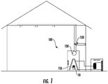
- an air conditioning system 100 is schematically shown in FIG. 1 , which incorporates the refrigerant detection assembly 10 of FIG. 2 .
- the air conditioning system 100 includes a refrigerant detection assembly 10 located proximate to the indoor heat exchanger 110.
- the air conditioning system 100 is provided for use within a building, such as a residential or commercial building, and may be configured as a ductless or ducted system. For purposes of clarity and brevity, however, the following description will relate to the exemplary use of the air conditioning system 100 as a ducted system.
- the air conditioning system 100 includes an indoor unit and an outdoor unit, the indoor unit containing an indoor heat exchanger 110 and the outdoor unit containing an outdoor heat exchanger.
- the indoor heat exchanger 110 absorbs heat from the air being passed through the air conditioning system 100.
- the cooled air is then circulated into the building by way of the air ducts.
- the outdoor unit in addition to including an outdoor heat exchanger, also includes a fan and a compressor.
- the outdoor heat exchanger in combination with the fan, operates to absorb heat from the refrigerant being passed through the outdoor unit.
- the compressor in the outdoor unit pumps the refrigerant in a cyclical manner through the air conditioning system 100. This refrigerant may, in rare instances, leak into the air conditioning system 100.
- the air conditioning system provides a refrigerant detection assembly 10 located proximate to the indoor heat exchanger 110.
- the refrigerant detection assembly 10 is attached to the indoor heat exchanger 110.
- the refrigerant detection assembly 10 may be attached to the sheet metal of the coils delta plate of the indoor heat exchanger 110.
- the refrigerant detection assembly 10 includes a nondispersive infrared sensor 11, a fan 12 disposed adjacent to the nondispersive infrared sensor 11, the fan 12 configured to direct a sample to the nondispersive infrared sensor 11, a controller 13 operatively connected to the nondispersive infrared sensor 11 and the fan 12.
- the controller 13 is configured to operate the fan 12 in constant operation and trigger a response when the refrigerant detection assembly 10 detects at least 25% lower flammability limit (LFL) in the sample.
- LFL lower flammability limit
- the controller 13 of the refrigerant detection assembly 10 is configured to trigger a response within ten seconds of the sample reaching 100% lower flammability limit.
- the response triggered by the controller 13 may include at least one of: an alarm signal, stopping operation of the air conditioning system 100, operating a zoning damper 120, and operating an indoor fan 130 of the air conditioning system 100.
- the controller 13 may encourage the dilution of refrigerant in the building or air conditioning system 100 by directing the air from the air conditioning system 100 outside the building.
- the controller operates both the zoning damper 120 and the indoor fan 130 of the air conditioning system to direct the air from the air conditioning system 100 outside the building.
- the air conditioning system 100 is capable of redirecting air outside the building when potentially hazardous conditions are present.
- the stopping operation of the air conditioning system 100 triggered by the controller 13 includes at least shutting off of the compressor in the outdoor unit to discontinue the circulation of refrigerant between the outdoor unit and the indoor unit.
- the fan 12 of the refrigerant detection assembly 10 is operated in a continuous manner by the controller 13.
- the continuous operation of the fan 12 should not be interpreted as operating for a brief period of time in order to establish a calibration (ex. calibration of the NDIR sensor), but instead should be interpreted as the uninterrupted running of the fan 12 by the controller 13 to constantly direct a sample toward the NDIR sensor 11.
- the refrigerant detection assembly 10 enables a reduced response time for detecting a leak in the air conditioning system 100 than what otherwise would be possible without the use of a fan 12.
- the refrigerant detection assembly 10 triggers a response when the NDIR sensor 11 detects at least a 25% LFL in the sample. This 25% LFL in the sample may be reached by a leak of at least one A2L refrigerant.
- the configuration and method in which the refrigerant detection assembly 10 is used reduces the response time for detecting a refrigerant leak such that effective safety measures can be initiated.
- the method 300 includes step 310 of operating a refrigerant detection assembly 10, the refrigerant detection assembly 10 including a nondispersive infrared sensor 11, a fan 12 disposed adjacent to the nondispersive infrared sensor 11, and a controller 13 operatively connected to the fan 12.
- the method 300 further includes step 320 of directing a sample to the nondispersive infrared sensor 11 continuously with the fan 12. To ensure that the fan 12 is operated continuously, in certain instances, the controller 13 is operatively connected to the fan.
- the method 300 further includes step 330 for triggering a response with the controller 13 when the sensor 11 detects at least 25% lower flammability limit in the sample.
- the 25% LFL in the sample may be reached by a leak of at least one A2L refrigerant.
- the response is triggered within ten seconds of the sample reaching 100% LFL.
- the response triggered by the controller 13 may include at least one of: an alarm signal, stopping operation of the air conditioning system 100, operating a zoning damper 120, and operating an indoor fan 130 of the air conditioning system 100. The response may make it possible to mitigate the potentially hazardous conditions.
Landscapes
- Engineering & Computer Science (AREA)
- Chemical & Material Sciences (AREA)
- General Engineering & Computer Science (AREA)
- Combustion & Propulsion (AREA)
- Mechanical Engineering (AREA)
- Physics & Mathematics (AREA)
- Life Sciences & Earth Sciences (AREA)
- Health & Medical Sciences (AREA)
- Fluid Mechanics (AREA)
- Analytical Chemistry (AREA)
- Biochemistry (AREA)
- General Health & Medical Sciences (AREA)
- General Physics & Mathematics (AREA)
- Immunology (AREA)
- Pathology (AREA)
- Air Conditioning Control Device (AREA)
- Examining Or Testing Airtightness (AREA)
Abstract
Description
- The subject matter disclosed herein relates to detecting leaks of moderate-to-low global warming potential (GWP) value refrigerants. More particularly, the subject matter disclosed herein relates to a refrigerant detection assembly for detecting moderate-to-low GWP value refrigerants, an air conditioning system for incorporating the same, and a method of detecting refrigerant leaks using the refrigerant detection assembly.
- Air conditioning systems for residential or commercial buildings typically include an outdoor unit and an indoor unit. The indoor unit contains an indoor heat exchanger, which absorbs heat from the air being passed through the system using a refrigerant when the system is operating in cooling mode. The outdoor unit contains an outdoor heat exchanger, which cools and condenses the gaseous refrigerant when the system is operating in cooling mode. This refrigerant, historically, has been provided as a fluid with a high GWP value such as R134A or R410A. Although these refrigerants are effective coolants, the effect they can have on the environment has led to the institution of requirements that new refrigerants, which have moderate-to-low GWP values, be employed instead.
- Moderate-to-low GWP refrigerants (i.e. A2L refrigerants) can be mildly flammable, however, and thus their use in air conditioning systems can present risks that needs to be addressed. In particular, to the extent that refrigerant leaks are possible in air conditioning systems, it is desirable to have leak detection systems in place when A2L refrigerants are in use for indoor units for ducted residential heating, ventilation and air conditioning (HVAC) products and other similar systems.
- One of the existing technologies available to detect refrigeration leaks is a nondispersive infrared sensor (NDIR). However, a current limitation of using a NDIR sensor is the high response time in comparison with other technologies. Such response time is critical to ensure effective safety measures. Accordingly, there remains a need to for a refrigeration detection assembly with an acceptable response time to detect leaks of A2L refrigerant.
- According to a first aspect of the invention, an air conditioning system is provided, which includes an indoor heat exchanger and a refrigerant detection assembly disposed proximate to an indoor heat exchanger. The refrigerant detection assembly includes a nondispersive infrared (NDIR) sensor, a fan disposed adjacent to the nondispersive infrared sensor, the fan configured to direct a sample to the nondispersive infrared sensor, and a controller operatively connected to the nondispersive infrared sensor and the fan. The controller is configured to operate the fan in constant operation and trigger a response when the refrigerant detection assembly detects at least 25% lower flammability limit (LFL) in the sample.
- The nondispersive infrared sensor may be configured to detect at least one A2L refrigerant.
- The response may be triggered within ten seconds of the sample reaching 100% lower flammability limit.
- The response may include at least one of: an alarm signal, stopping operation of the system, opening a zoning damper, and operating an indoor fan.
- The refrigerant detection assembly may be attached to the indoor heat exchanger.
- According to another aspect of the invention, a refrigerant detection assembly is provided, which includes a nondispersive infrared (NDIR) sensor, a fan configured to direct a sample to the nondispersive infrared sensor, and a controller operatively connected to the fan. The controller is configured to operate the fan in constant operation and trigger a response when the sensor detects at least 25% lower flammability limit in the sample.
- The at least 25% lower flammability limit in the sample may be reached by a leak of at least one A2L refrigerant.
- The response may be triggered within ten seconds of the sample reaching 100% lower flammability limit.
- The response may include at least one of: an alarm signal, stopping operation of the system, operating a zoning damper, and operating an indoor fan of an air conditioning system.
- According to another aspect of the invention, a method for detecting a refrigerant leak using a refrigerant detection assembly is provided. The method provides for the operating of a nondispersive infrared sensor, directing of a sample to the nondispersive infrared sensor continuously with a fan, and triggering a response with a controller when the sensor detects at least 25% lower flammability in the sample. The refrigerant detection assembly includes the nondispersive infrared (NDIR) sensor, a fan disposed adjacent to the nondispersive infrared sensor, and a controller operatively connected to the fan.
- The controller may be operatively connected to the fan to operate the fan continuously.
- The at least 25% lower flammability limit in the sample may be reached by a leak of at least one A2L refrigerant.
- The response may be triggered within ten seconds of the sample reaching 100% lower flammability limit.
- The response may include at least one of: an alarm signal, stopping operation of the system, opening a zoning damper, and operating an indoor fan of an air conditioning system
- The subject matter, which is regarded as the disclosure, is particularly pointed out and distinctly claimed in the claims at the conclusion of the specification. The following descriptions of the drawings are by way of example only and should not be considered limiting in any way. With reference to the accompanying drawings, like elements are numbered alike:
-
FIG. 1 is a schematic illustration of an air conditioning system -
FIG. 2 is a perspective view of a refrigerant detection assembly -
FIG. 3 is a flow diagram illustrating a method of detecting a refrigerant leak. - As will be described below, a refrigerant detection assembly, an air conditioning system for incorporating the same, and a method of detecting refrigerant leaks using the refrigerant detection assembly are provided. The refrigerant detection assembly enables the detection of leaks within ten seconds of being exposed to 100% lower flammability limit (LFL). The refrigerant detection assembly utilizes a nondispersive infrared (NDIR) sensor. The refrigerant detection assembly overcomes the high response time traditionally associated with nondispersive infrared sensors by incorporating a fan to force a sample into the NDIR sensor. This sample will contain an air and refrigerant mixture when there is a leak in the air conditioning system. By forcing the sample into the NDIR sensor, the fan effectively reduces the amount of time it takes for the refrigerant to diffuse into the NDIR sensor thereby reducing the response time of detecting a leak. For example, the refrigerant detection assembly may be capable of detecting a leak of at least one A2L refrigerant.
- The classification of refrigerant is based upon American Society of Heating, Refrigerating and Air-Conditioning (ASHRAE) Standard 34. The standard evaluates each refrigerant's flammability and toxicity and gives it a class referenced as a letter and number combination. The letter refers to the refrigerants toxicity, and is based on the particular refrigerant's occupational exposure limit (OEL). An "A" is given to refrigerants with a 400 ppm or greater OEL. A "B" is given to refrigerants with less than 400 ppm OEL. The number adjacent to the letter refers to the refrigerants flammability, and is based on the burning velocity (BV), heat of combustion (HOC), and lower flammability limits (LFL) of the particular refrigerant. A flammability of "1" is the lowest, with a "3" being the highest. Recently the second class was broken into "2L" and "2". A rating of "2L" indicates that while the refrigerant is still considered flammable, its flammability is much lower than that of class 2 or 3. It is envisioned that the refrigerant detection assembly described herein may be capable of detecting a leak and triggering a response of at least one A2L refrigerant when the NDIR sensor detects at least 25% LFL in the sample.
- A lower flammability limit (LFL) of a refrigerant is the minimum concentration limit that is required for the refrigerant to become potentially combustible. For example, R-32, which is an A2L refrigerant, has a LFL of 13.3%. A 25% LFL value is one quarter of the value of the LFL. For example, R-32 has a 25% LFL value of 3.3%. For illustrative purposes, if the R-32 were used as the refrigerant in the air conditioning system, the refrigerant detection assembly may be configured to trigger a response when the NDIR sensor detects at least 3.3% of R-32 in the sample. In certain instances, the refrigerant detection assembly may make it possible to trigger a response within ten seconds of the sample reaching 100% LFL. For example, if using R-32 as the refrigerant, the refrigerant detection assembly may make it possible to trigger a response within ten seconds of the sample containing 13.3% R-32.
- With reference now to the Figures, an
air conditioning system 100 is schematically shown inFIG. 1 , which incorporates therefrigerant detection assembly 10 ofFIG. 2 . As shown inFIG. 1 , theair conditioning system 100 includes arefrigerant detection assembly 10 located proximate to theindoor heat exchanger 110. Theair conditioning system 100 is provided for use within a building, such as a residential or commercial building, and may be configured as a ductless or ducted system. For purposes of clarity and brevity, however, the following description will relate to the exemplary use of theair conditioning system 100 as a ducted system. - In certain instances, the
air conditioning system 100 includes an indoor unit and an outdoor unit, the indoor unit containing anindoor heat exchanger 110 and the outdoor unit containing an outdoor heat exchanger. When operating in cooling mode, theindoor heat exchanger 110 absorbs heat from the air being passed through theair conditioning system 100. The cooled air is then circulated into the building by way of the air ducts. The outdoor unit, in addition to including an outdoor heat exchanger, also includes a fan and a compressor. When operating in cooling mode, the outdoor heat exchanger, in combination with the fan, operates to absorb heat from the refrigerant being passed through the outdoor unit. The compressor in the outdoor unit pumps the refrigerant in a cyclical manner through theair conditioning system 100. This refrigerant may, in rare instances, leak into theair conditioning system 100. When utilizing A2L refrigerants in theair conditioning system 100, a leak of refrigerant could lead to undesirable consequences due to the mildly flammable nature of A2L refrigerants. To identify leaks in theair conditioning system 100, the air conditioning system provides arefrigerant detection assembly 10 located proximate to theindoor heat exchanger 110. In certain instances, therefrigerant detection assembly 10 is attached to theindoor heat exchanger 110. For example, therefrigerant detection assembly 10 may be attached to the sheet metal of the coils delta plate of theindoor heat exchanger 110. - An exemplary embodiment of the
refrigerant detection assembly 10 is shown inFIG. 2 . As shown inFIG. 2 , therefrigerant detection assembly 10 includes a nondispersiveinfrared sensor 11, afan 12 disposed adjacent to the nondispersiveinfrared sensor 11, thefan 12 configured to direct a sample to the nondispersiveinfrared sensor 11, acontroller 13 operatively connected to the nondispersiveinfrared sensor 11 and thefan 12. Thecontroller 13 is configured to operate thefan 12 in constant operation and trigger a response when therefrigerant detection assembly 10 detects at least 25% lower flammability limit (LFL) in the sample. In certain instances, thecontroller 13 of therefrigerant detection assembly 10 is configured to trigger a response within ten seconds of the sample reaching 100% lower flammability limit. - In instances where the
refrigerant detection assembly 10 detects a leak (ex. when therefrigerant detection assembly 10 detects at least 25% LFL in the sample) in theair conditioning system 100, the response triggered by thecontroller 13 may include at least one of: an alarm signal, stopping operation of theair conditioning system 100, operating azoning damper 120, and operating anindoor fan 130 of theair conditioning system 100. For example, thecontroller 13 may encourage the dilution of refrigerant in the building orair conditioning system 100 by directing the air from theair conditioning system 100 outside the building. In certain instances, the controller operates both thezoning damper 120 and theindoor fan 130 of the air conditioning system to direct the air from theair conditioning system 100 outside the building. By utilizing azoning damper 120, theair conditioning system 100 is capable of redirecting air outside the building when potentially hazardous conditions are present. In certain instances, the stopping operation of theair conditioning system 100 triggered by thecontroller 13 includes at least shutting off of the compressor in the outdoor unit to discontinue the circulation of refrigerant between the outdoor unit and the indoor unit. - To ensure that the
air conditioning system 100 is effectively monitored for leaks, thefan 12 of therefrigerant detection assembly 10 is operated in a continuous manner by thecontroller 13. The continuous operation of thefan 12 should not be interpreted as operating for a brief period of time in order to establish a calibration (ex. calibration of the NDIR sensor), but instead should be interpreted as the uninterrupted running of thefan 12 by thecontroller 13 to constantly direct a sample toward theNDIR sensor 11. By running in a continuous manner, therefrigerant detection assembly 10 enables a reduced response time for detecting a leak in theair conditioning system 100 than what otherwise would be possible without the use of afan 12. In certain instances, therefrigerant detection assembly 10 triggers a response when theNDIR sensor 11 detects at least a 25% LFL in the sample. This 25% LFL in the sample may be reached by a leak of at least one A2L refrigerant. The configuration and method in which therefrigerant detection assembly 10 is used reduces the response time for detecting a refrigerant leak such that effective safety measures can be initiated. - The method of detecting a refrigerant leak using the
refrigerant detection assembly 10 is illustrated inFIG. 3 . As shown inFIG. 3 , themethod 300 includesstep 310 of operating arefrigerant detection assembly 10, therefrigerant detection assembly 10 including a nondispersiveinfrared sensor 11, afan 12 disposed adjacent to the nondispersiveinfrared sensor 11, and acontroller 13 operatively connected to thefan 12. Themethod 300 further includesstep 320 of directing a sample to the nondispersiveinfrared sensor 11 continuously with thefan 12. To ensure that thefan 12 is operated continuously, in certain instances, thecontroller 13 is operatively connected to the fan. Themethod 300 further includesstep 330 for triggering a response with thecontroller 13 when thesensor 11 detects at least 25% lower flammability limit in the sample. The 25% LFL in the sample may be reached by a leak of at least one A2L refrigerant. In certain instances, the response is triggered within ten seconds of the sample reaching 100% LFL. When thesensor 11 detects at least 25% LFL in the sample, the response triggered by thecontroller 13 may include at least one of: an alarm signal, stopping operation of theair conditioning system 100, operating azoning damper 120, and operating anindoor fan 130 of theair conditioning system 100. The response may make it possible to mitigate the potentially hazardous conditions. - While the present disclosure has been described with reference to an exemplary embodiment or embodiments, it will be understood by those skilled in the art that various changes may be made and equivalents may be substituted for elements thereof without departing from the scope of the present invention as defined by the claims. In addition, many modifications may be made to adapt a particular situation or material to the teachings of the present disclosure. Therefore, it is intended that the present invention not be limited to the particular embodiment disclosed for carrying out this present disclosure, but that the present invention will include all embodiments falling within the scope of the claims.
Claims (12)
- A refrigerant detection assembly (10), comprising:a nondispersive infrared sensor (11);a fan (12) configured to direct a sample to the nondispersive infrared sensor (11); anda controller (13) operatively connected to the fan (12), the controller configured to:operate the fan (12) in constant operation, andtrigger a response when the sensor (11) detects at least 25% lower flammability limit in the sample.
- The refrigerant detection assembly (10) of claim 1, wherein the at least 25% lower flammability limit in the sample is reached by a leak of at least one A2L refrigerant.
- The refrigerant detection assembly (10) of claim 1 or 2, wherein the response is triggered within ten seconds of the sample reaching 100% lower flammability limit.
- The refrigerant detection assembly (10) of claim 1, 2, or 3, wherein the response comprises at least one of: an alarm signal, stopping operation of the system, opening a zoning damper (120), and operating an indoor fan (130) of an air conditioning system.
- An air conditioning system (100), comprising:an indoor heat exchanger (110); andthe refrigerant detection assembly (10) of any preceding claim located proximate to the indoor heat exchanger (110), wherein the fan (12) is disposed adjacent to the nondispersive infrared sensor (11), and the controller (13) is operatively connected to the nondispersive infrared sensor (11).
- The air conditioning system (100) of claim 5, wherein the nondispersive infrared sensor (11) is configured to detect at least one A2L refrigerant.
- The air conditioning system (100) of claim 5 or 6, wherein the refrigerant detection assembly (10) is attached to the indoor heat exchanger (110).
- A method for detecting a refrigerant leak, the method comprising:operating a refrigerant detection assembly (10), the refrigerant detection assembly including a nondispersive infrared sensor (11), a fan (12) disposed adjacent to the nondispersive infrared sensor, and a controller (13) operatively connected to the fan;directing a sample to the nondispersive infrared sensor (11) continuously with the fan (12); andtriggering a response with the controller (13) when the sensor (11) detects at least 25% lower flammability in the sample.
- The method of claim 8, wherein the controller (13) is operatively connected to the fan (12) to operate the fan continuously.
- The method of claim 8 or 9, wherein the at least 25% lower flammability limit in the sample is reached by a leak of at least one A2L refrigerant.
- The method of claim 8, 9, or 10, wherein the response is triggered within ten seconds of the sample reaching 100% lower flammability limit.
- The method of any of claims 8 to 11, wherein the response comprises at least one of: an alarm signal, stopping operation of the system, opening a zoning damper (120), and operating an indoor fan (130) of an air conditioning system (100).
Applications Claiming Priority (1)
| Application Number | Priority Date | Filing Date | Title |
|---|---|---|---|
| US201962915295P | 2019-10-15 | 2019-10-15 |
Publications (2)
| Publication Number | Publication Date |
|---|---|
| EP3809056A1 true EP3809056A1 (en) | 2021-04-21 |
| EP3809056B1 EP3809056B1 (en) | 2025-08-06 |
Family
ID=73138580
Family Applications (1)
| Application Number | Title | Priority Date | Filing Date |
|---|---|---|---|
| EP20202015.2A Active EP3809056B1 (en) | 2019-10-15 | 2020-10-15 | Refrigerant detection assembly and air conditioning system comprising the same |
Country Status (3)
| Country | Link |
|---|---|
| US (1) | US11408624B2 (en) |
| EP (1) | EP3809056B1 (en) |
| CN (1) | CN112665106A (en) |
Families Citing this family (16)
| Publication number | Priority date | Publication date | Assignee | Title |
|---|---|---|---|---|
| US10119738B2 (en) | 2014-09-26 | 2018-11-06 | Waterfurnace International Inc. | Air conditioning system with vapor injection compressor |
| US10871314B2 (en) | 2016-07-08 | 2020-12-22 | Climate Master, Inc. | Heat pump and water heater |
| US10866002B2 (en) | 2016-11-09 | 2020-12-15 | Climate Master, Inc. | Hybrid heat pump with improved dehumidification |
| US11592215B2 (en) | 2018-08-29 | 2023-02-28 | Waterfurnace International, Inc. | Integrated demand water heating using a capacity modulated heat pump with desuperheater |
| CA3081986A1 (en) | 2019-07-15 | 2021-01-15 | Climate Master, Inc. | Air conditioning system with capacity control and controlled hot water generation |
| US11231198B2 (en) | 2019-09-05 | 2022-01-25 | Trane International Inc. | Systems and methods for refrigerant leak detection in a climate control system |
| US11668483B2 (en) * | 2021-02-01 | 2023-06-06 | Goodman Manufacturing Company LP | Systems and methods for air temperature control including A2L sensors |
| US11662110B2 (en) | 2021-02-01 | 2023-05-30 | Goodman Manufacturing Company LP | Systems and methods for air temperature control including R-32 sensors |
| US11920805B2 (en) | 2021-02-01 | 2024-03-05 | Goodman Manufacturing Company LP | Systems and methods for air temperature control using A2L refrigerants |
| US12235001B2 (en) | 2021-02-01 | 2025-02-25 | Goodman Manufacturing Company LP | Systems and methods for air temperature control including R-454b sensors |
| US12379308B2 (en) | 2021-09-30 | 2025-08-05 | Carrier Corporation | Environmental enclosure for a transport gas sensor |
| US12410926B2 (en) | 2021-10-05 | 2025-09-09 | Carrier Corporation | Frost remidiation and frost sensor |
| US12181189B2 (en) | 2021-11-10 | 2024-12-31 | Climate Master, Inc. | Ceiling-mountable heat pump system |
| US12487008B2 (en) | 2022-01-14 | 2025-12-02 | Trane International Inc. | Method of commissioning an HVAC system |
| US12117191B2 (en) | 2022-06-24 | 2024-10-15 | Trane International Inc. | Climate control system with improved leak detector |
| US12504189B2 (en) * | 2023-06-27 | 2025-12-23 | Lennox Industries Inc. | Refrigerant leak detection system and method |
Citations (3)
| Publication number | Priority date | Publication date | Assignee | Title |
|---|---|---|---|---|
| US20140223931A1 (en) * | 2013-02-12 | 2014-08-14 | Hussmann Corporation | Control system for a refrigerated merchandiser |
| CN108351137A (en) * | 2015-11-09 | 2018-07-31 | 开利公司 | Shunt circuit intermodal container |
| WO2018187450A1 (en) * | 2017-04-06 | 2018-10-11 | Carrier Corporation | Moderate-to-low global warming potential value refrigerant leak detection |
Family Cites Families (22)
| Publication number | Priority date | Publication date | Assignee | Title |
|---|---|---|---|---|
| DE102004030855A1 (en) | 2004-06-25 | 2006-01-12 | Tyco Electronics Raychem Gmbh | Method for reducing condensation in gas sensor arrangements |
| US9164519B2 (en) * | 2009-09-15 | 2015-10-20 | Cooper Technologies Company | Smart environmental control system for an enclosure with diagnostics |
| JP2014224612A (en) * | 2011-09-16 | 2014-12-04 | パナソニック株式会社 | Air conditioner |
| JP2014035171A (en) * | 2012-08-10 | 2014-02-24 | Mitsubishi Electric Corp | Air conditioner, air conditioning method and program |
| JP5812081B2 (en) * | 2013-11-12 | 2015-11-11 | ダイキン工業株式会社 | Indoor unit |
| US10488065B2 (en) * | 2014-12-17 | 2019-11-26 | Carrier Corporation | Leak detection unit for refrigerant system |
| JP6466219B2 (en) * | 2015-03-20 | 2019-02-06 | 日立ジョンソンコントロールズ空調株式会社 | Air conditioner indoor unit |
| WO2016157538A1 (en) * | 2015-04-03 | 2016-10-06 | 三菱電機株式会社 | Refrigeration cycle device |
| DK3329264T3 (en) * | 2015-07-28 | 2020-03-09 | Carrier Corp | Refrigerant analyzer and method of use thereof |
| US20180327179A1 (en) * | 2015-11-09 | 2018-11-15 | Carrier Corporation | Refrigerated Transport System with Refrigerant Dilution |
| WO2017109847A1 (en) * | 2015-12-22 | 2017-06-29 | 三菱電機株式会社 | Air conditioner |
| CN105823170B (en) * | 2016-03-15 | 2018-12-04 | 合肥通用机械研究院有限公司 | A comprehensive test device for refrigeration and air conditioning with explosion-proof function |
| EP3450884B1 (en) * | 2016-04-27 | 2022-03-02 | Mitsubishi Electric Corporation | Refrigeration cycle apparatus |
| AU2016404760B2 (en) * | 2016-04-28 | 2019-10-24 | Mitsubishi Electric Corporation | Refrigeration cycle apparatus |
| WO2017199342A1 (en) * | 2016-05-17 | 2017-11-23 | 三菱電機株式会社 | Refrigeration cycle device |
| WO2017213894A1 (en) | 2016-06-06 | 2017-12-14 | Honeywell International Inc. | Electrochemical gas sensor for use in ultra low oxygen storage environments |
| CN110226071B (en) * | 2017-02-01 | 2023-09-22 | 三菱电机株式会社 | Air conditioner |
| WO2018209082A1 (en) | 2017-05-12 | 2018-11-15 | Carrier Corporation | Sensor and method for gas testing |
| WO2018215069A1 (en) | 2017-05-24 | 2018-11-29 | Fraunhofer-Gesellschaft zur Förderung der angewandten Forschung e.V. | Sensor for sensing analytes using hybrid organic-inorganic sensing material |
| EP3712533B1 (en) * | 2017-11-16 | 2023-09-20 | Hitachi-Johnson Controls Air Conditioning, Inc. | Air conditioner |
| US11098915B2 (en) * | 2019-02-26 | 2021-08-24 | Lennox Industries Inc. | HVAC systems and methods with refrigerant purge |
| US11125457B1 (en) * | 2020-07-16 | 2021-09-21 | Emerson Climate Technologies, Inc. | Refrigerant leak sensor and mitigation device and methods |
-
2020
- 2020-09-25 US US16/948,621 patent/US11408624B2/en active Active
- 2020-10-15 CN CN202011102218.XA patent/CN112665106A/en active Pending
- 2020-10-15 EP EP20202015.2A patent/EP3809056B1/en active Active
Patent Citations (3)
| Publication number | Priority date | Publication date | Assignee | Title |
|---|---|---|---|---|
| US20140223931A1 (en) * | 2013-02-12 | 2014-08-14 | Hussmann Corporation | Control system for a refrigerated merchandiser |
| CN108351137A (en) * | 2015-11-09 | 2018-07-31 | 开利公司 | Shunt circuit intermodal container |
| WO2018187450A1 (en) * | 2017-04-06 | 2018-10-11 | Carrier Corporation | Moderate-to-low global warming potential value refrigerant leak detection |
Also Published As
| Publication number | Publication date |
|---|---|
| EP3809056B1 (en) | 2025-08-06 |
| US11408624B2 (en) | 2022-08-09 |
| US20210108820A1 (en) | 2021-04-15 |
| CN112665106A (en) | 2021-04-16 |
Similar Documents
| Publication | Publication Date | Title |
|---|---|---|
| EP3809056B1 (en) | Refrigerant detection assembly and air conditioning system comprising the same | |
| US12025337B2 (en) | Baffle for directing refrigerant leaks | |
| US11920806B2 (en) | Ultraviolet (UV) light-based refrigerant leak detection system and method | |
| US11835244B2 (en) | Evaporator with one or more leak mitigation dampers | |
| US12018869B2 (en) | System and method for mitigating risk from a leaked refrigerant at evaporator coils | |
| CN203672016U (en) | Air conditioner | |
| JP6785883B2 (en) | Air conditioner | |
| US20190170600A1 (en) | Systems and methods for detecting refrigerant leaks in heating, ventilating, and air conditioning (hvac) systems | |
| EP4163560B1 (en) | Frost remidiation and frost sensor | |
| EP3633282B1 (en) | Air conditioning device | |
| US20220333806A1 (en) | Dual temperature sensor arrangement to detect refrigerant leak | |
| US20220090833A1 (en) | Refrigerant cycle apparatus | |
| JP6624811B2 (en) | Refrigeration air conditioner | |
| WO2017187618A1 (en) | Refrigeration cycle apparatus | |
| WO2017081735A1 (en) | Refrigeration cycle device and refrigerant leak detection method | |
| WO2017002214A1 (en) | Refrigeration cycle system | |
| WO2018220758A1 (en) | Air-conditioning apparatus | |
| US11733723B2 (en) | Economizer temperature extrapolation systems and methods | |
| US20220325929A1 (en) | Initial power up or power outage refrigerant purge | |
| US12366392B2 (en) | Refrigerant cycle system and method | |
| JP2015215111A (en) | Heat pump device | |
| US10663936B2 (en) | Remote clear of an HVAC system | |
| US12031732B2 (en) | Air conditioning system, operation control method therefor, and operation control device for air conditioning system | |
| TR2023017514A2 (en) | A Working Method for Air Conditioning Devices. |
Legal Events
| Date | Code | Title | Description |
|---|---|---|---|
| PUAI | Public reference made under article 153(3) epc to a published international application that has entered the european phase |
Free format text: ORIGINAL CODE: 0009012 |
|
| STAA | Information on the status of an ep patent application or granted ep patent |
Free format text: STATUS: THE APPLICATION HAS BEEN PUBLISHED |
|
| AK | Designated contracting states |
Kind code of ref document: A1 Designated state(s): AL AT BE BG CH CY CZ DE DK EE ES FI FR GB GR HR HU IE IS IT LI LT LU LV MC MK MT NL NO PL PT RO RS SE SI SK SM TR |
|
| AX | Request for extension of the european patent |
Extension state: BA ME |
|
| STAA | Information on the status of an ep patent application or granted ep patent |
Free format text: STATUS: REQUEST FOR EXAMINATION WAS MADE |
|
| 17P | Request for examination filed |
Effective date: 20211018 |
|
| RBV | Designated contracting states (corrected) |
Designated state(s): AL AT BE BG CH CY CZ DE DK EE ES FI FR GB GR HR HU IE IS IT LI LT LU LV MC MK MT NL NO PL PT RO RS SE SI SK SM TR |
|
| STAA | Information on the status of an ep patent application or granted ep patent |
Free format text: STATUS: EXAMINATION IS IN PROGRESS |
|
| 17Q | First examination report despatched |
Effective date: 20221206 |
|
| GRAP | Despatch of communication of intention to grant a patent |
Free format text: ORIGINAL CODE: EPIDOSNIGR1 |
|
| STAA | Information on the status of an ep patent application or granted ep patent |
Free format text: STATUS: GRANT OF PATENT IS INTENDED |
|
| INTG | Intention to grant announced |
Effective date: 20250507 |
|
| GRAS | Grant fee paid |
Free format text: ORIGINAL CODE: EPIDOSNIGR3 |
|
| GRAA | (expected) grant |
Free format text: ORIGINAL CODE: 0009210 |
|
| STAA | Information on the status of an ep patent application or granted ep patent |
Free format text: STATUS: THE PATENT HAS BEEN GRANTED |
|
| AK | Designated contracting states |
Kind code of ref document: B1 Designated state(s): AL AT BE BG CH CY CZ DE DK EE ES FI FR GB GR HR HU IE IS IT LI LT LU LV MC MK MT NL NO PL PT RO RS SE SI SK SM TR |
|
| REG | Reference to a national code |
Ref country code: GB Ref legal event code: FG4D |
|
| REG | Reference to a national code |
Ref country code: CH Ref legal event code: EP |
|
| REG | Reference to a national code |
Ref country code: DE Ref legal event code: R096 Ref document number: 602020055852 Country of ref document: DE |
|
| REG | Reference to a national code |
Ref country code: IE Ref legal event code: FG4D |
|
| PGFP | Annual fee paid to national office [announced via postgrant information from national office to epo] |
Ref country code: GB Payment date: 20250923 Year of fee payment: 6 |
|
| PGFP | Annual fee paid to national office [announced via postgrant information from national office to epo] |
Ref country code: FR Payment date: 20250925 Year of fee payment: 6 |
|
| REG | Reference to a national code |
Ref country code: NL Ref legal event code: MP Effective date: 20250806 |
|
| PG25 | Lapsed in a contracting state [announced via postgrant information from national office to epo] |
Ref country code: IS Free format text: LAPSE BECAUSE OF FAILURE TO SUBMIT A TRANSLATION OF THE DESCRIPTION OR TO PAY THE FEE WITHIN THE PRESCRIBED TIME-LIMIT Effective date: 20251206 |
|
| PGFP | Annual fee paid to national office [announced via postgrant information from national office to epo] |
Ref country code: DE Payment date: 20250923 Year of fee payment: 6 |
|
| PG25 | Lapsed in a contracting state [announced via postgrant information from national office to epo] |
Ref country code: NO Free format text: LAPSE BECAUSE OF FAILURE TO SUBMIT A TRANSLATION OF THE DESCRIPTION OR TO PAY THE FEE WITHIN THE PRESCRIBED TIME-LIMIT Effective date: 20251106 |
|
| REG | Reference to a national code |
Ref country code: LT Ref legal event code: MG9D |
|
| PG25 | Lapsed in a contracting state [announced via postgrant information from national office to epo] |
Ref country code: PT Free format text: LAPSE BECAUSE OF FAILURE TO SUBMIT A TRANSLATION OF THE DESCRIPTION OR TO PAY THE FEE WITHIN THE PRESCRIBED TIME-LIMIT Effective date: 20251209 |
|
| PG25 | Lapsed in a contracting state [announced via postgrant information from national office to epo] |
Ref country code: FI Free format text: LAPSE BECAUSE OF FAILURE TO SUBMIT A TRANSLATION OF THE DESCRIPTION OR TO PAY THE FEE WITHIN THE PRESCRIBED TIME-LIMIT Effective date: 20250806 |
|
| PG25 | Lapsed in a contracting state [announced via postgrant information from national office to epo] |
Ref country code: HR Free format text: LAPSE BECAUSE OF FAILURE TO SUBMIT A TRANSLATION OF THE DESCRIPTION OR TO PAY THE FEE WITHIN THE PRESCRIBED TIME-LIMIT Effective date: 20250806 Ref country code: NL Free format text: LAPSE BECAUSE OF FAILURE TO SUBMIT A TRANSLATION OF THE DESCRIPTION OR TO PAY THE FEE WITHIN THE PRESCRIBED TIME-LIMIT Effective date: 20250806 |
|
| PG25 | Lapsed in a contracting state [announced via postgrant information from national office to epo] |
Ref country code: GR Free format text: LAPSE BECAUSE OF FAILURE TO SUBMIT A TRANSLATION OF THE DESCRIPTION OR TO PAY THE FEE WITHIN THE PRESCRIBED TIME-LIMIT Effective date: 20251107 |
|
| PG25 | Lapsed in a contracting state [announced via postgrant information from national office to epo] |
Ref country code: SE Free format text: LAPSE BECAUSE OF FAILURE TO SUBMIT A TRANSLATION OF THE DESCRIPTION OR TO PAY THE FEE WITHIN THE PRESCRIBED TIME-LIMIT Effective date: 20250806 |
|
| PG25 | Lapsed in a contracting state [announced via postgrant information from national office to epo] |
Ref country code: LV Free format text: LAPSE BECAUSE OF FAILURE TO SUBMIT A TRANSLATION OF THE DESCRIPTION OR TO PAY THE FEE WITHIN THE PRESCRIBED TIME-LIMIT Effective date: 20250806 |
|
| PG25 | Lapsed in a contracting state [announced via postgrant information from national office to epo] |
Ref country code: PL Free format text: LAPSE BECAUSE OF FAILURE TO SUBMIT A TRANSLATION OF THE DESCRIPTION OR TO PAY THE FEE WITHIN THE PRESCRIBED TIME-LIMIT Effective date: 20250806 Ref country code: BG Free format text: LAPSE BECAUSE OF FAILURE TO SUBMIT A TRANSLATION OF THE DESCRIPTION OR TO PAY THE FEE WITHIN THE PRESCRIBED TIME-LIMIT Effective date: 20250806 |
|
| PG25 | Lapsed in a contracting state [announced via postgrant information from national office to epo] |
Ref country code: RS Free format text: LAPSE BECAUSE OF FAILURE TO SUBMIT A TRANSLATION OF THE DESCRIPTION OR TO PAY THE FEE WITHIN THE PRESCRIBED TIME-LIMIT Effective date: 20251106 |
|
| PG25 | Lapsed in a contracting state [announced via postgrant information from national office to epo] |
Ref country code: ES Free format text: LAPSE BECAUSE OF FAILURE TO SUBMIT A TRANSLATION OF THE DESCRIPTION OR TO PAY THE FEE WITHIN THE PRESCRIBED TIME-LIMIT Effective date: 20250806 |
|
| REG | Reference to a national code |
Ref country code: AT Ref legal event code: MK05 Ref document number: 1822249 Country of ref document: AT Kind code of ref document: T Effective date: 20250806 |
|
| PG25 | Lapsed in a contracting state [announced via postgrant information from national office to epo] |
Ref country code: RO Free format text: LAPSE BECAUSE OF FAILURE TO SUBMIT A TRANSLATION OF THE DESCRIPTION OR TO PAY THE FEE WITHIN THE PRESCRIBED TIME-LIMIT Effective date: 20250806 |
|
| PG25 | Lapsed in a contracting state [announced via postgrant information from national office to epo] |
Ref country code: SM Free format text: LAPSE BECAUSE OF FAILURE TO SUBMIT A TRANSLATION OF THE DESCRIPTION OR TO PAY THE FEE WITHIN THE PRESCRIBED TIME-LIMIT Effective date: 20250806 |
|
| PG25 | Lapsed in a contracting state [announced via postgrant information from national office to epo] |
Ref country code: DK Free format text: LAPSE BECAUSE OF FAILURE TO SUBMIT A TRANSLATION OF THE DESCRIPTION OR TO PAY THE FEE WITHIN THE PRESCRIBED TIME-LIMIT Effective date: 20250806 |
|
| PG25 | Lapsed in a contracting state [announced via postgrant information from national office to epo] |
Ref country code: AT Free format text: LAPSE BECAUSE OF FAILURE TO SUBMIT A TRANSLATION OF THE DESCRIPTION OR TO PAY THE FEE WITHIN THE PRESCRIBED TIME-LIMIT Effective date: 20250806 |
|
| PG25 | Lapsed in a contracting state [announced via postgrant information from national office to epo] |
Ref country code: IT Free format text: LAPSE BECAUSE OF FAILURE TO SUBMIT A TRANSLATION OF THE DESCRIPTION OR TO PAY THE FEE WITHIN THE PRESCRIBED TIME-LIMIT Effective date: 20250806 |
|
| PG25 | Lapsed in a contracting state [announced via postgrant information from national office to epo] |
Ref country code: CZ Free format text: LAPSE BECAUSE OF FAILURE TO SUBMIT A TRANSLATION OF THE DESCRIPTION OR TO PAY THE FEE WITHIN THE PRESCRIBED TIME-LIMIT Effective date: 20250806 |
|
| PG25 | Lapsed in a contracting state [announced via postgrant information from national office to epo] |
Ref country code: SK Free format text: LAPSE BECAUSE OF FAILURE TO SUBMIT A TRANSLATION OF THE DESCRIPTION OR TO PAY THE FEE WITHIN THE PRESCRIBED TIME-LIMIT Effective date: 20250806 Ref country code: EE Free format text: LAPSE BECAUSE OF FAILURE TO SUBMIT A TRANSLATION OF THE DESCRIPTION OR TO PAY THE FEE WITHIN THE PRESCRIBED TIME-LIMIT Effective date: 20250806 |