EP3712533B1 - Air conditioner - Google Patents
Air conditioner Download PDFInfo
- Publication number
- EP3712533B1 EP3712533B1 EP17932192.2A EP17932192A EP3712533B1 EP 3712533 B1 EP3712533 B1 EP 3712533B1 EP 17932192 A EP17932192 A EP 17932192A EP 3712533 B1 EP3712533 B1 EP 3712533B1
- Authority
- EP
- European Patent Office
- Prior art keywords
- refrigerant
- leak
- controller
- air
- sealed
- Prior art date
- Legal status (The legal status is an assumption and is not a legal conclusion. Google has not performed a legal analysis and makes no representation as to the accuracy of the status listed.)
- Active
Links
- 239000003507 refrigerant Substances 0.000 claims description 329
- 238000005057 refrigeration Methods 0.000 claims description 6
- 238000000034 method Methods 0.000 description 38
- 238000004378 air conditioning Methods 0.000 description 13
- 238000012360 testing method Methods 0.000 description 13
- 230000000704 physical effect Effects 0.000 description 9
- 238000010586 diagram Methods 0.000 description 6
- 238000004891 communication Methods 0.000 description 5
- 238000009833 condensation Methods 0.000 description 3
- 230000005494 condensation Effects 0.000 description 3
- 238000001816 cooling Methods 0.000 description 3
- 230000000694 effects Effects 0.000 description 3
- 238000001704 evaporation Methods 0.000 description 3
- 230000008020 evaporation Effects 0.000 description 3
- 238000010438 heat treatment Methods 0.000 description 3
- 238000012546 transfer Methods 0.000 description 3
- CURLTUGMZLYLDI-UHFFFAOYSA-N Carbon dioxide Chemical compound O=C=O CURLTUGMZLYLDI-UHFFFAOYSA-N 0.000 description 2
- 230000006870 function Effects 0.000 description 2
- 239000007788 liquid Substances 0.000 description 2
- 238000012545 processing Methods 0.000 description 2
- 230000035945 sensitivity Effects 0.000 description 2
- 238000010792 warming Methods 0.000 description 2
- LVGUZGTVOIAKKC-UHFFFAOYSA-N 1,1,1,2-tetrafluoroethane Chemical compound FCC(F)(F)F LVGUZGTVOIAKKC-UHFFFAOYSA-N 0.000 description 1
- OHMHBGPWCHTMQE-UHFFFAOYSA-N 2,2-dichloro-1,1,1-trifluoroethane Chemical compound FC(F)(F)C(Cl)Cl OHMHBGPWCHTMQE-UHFFFAOYSA-N 0.000 description 1
- 239000004215 Carbon black (E152) Substances 0.000 description 1
- VOPWNXZWBYDODV-UHFFFAOYSA-N Chlorodifluoromethane Chemical compound FC(F)Cl VOPWNXZWBYDODV-UHFFFAOYSA-N 0.000 description 1
- 229910002092 carbon dioxide Inorganic materials 0.000 description 1
- 239000001569 carbon dioxide Substances 0.000 description 1
- 238000007084 catalytic combustion reaction Methods 0.000 description 1
- 238000012508 change request Methods 0.000 description 1
- 230000005484 gravity Effects 0.000 description 1
- 229930195733 hydrocarbon Natural products 0.000 description 1
- 150000002430 hydrocarbons Chemical class 0.000 description 1
- 238000009434 installation Methods 0.000 description 1
- 238000004519 manufacturing process Methods 0.000 description 1
- 239000000203 mixture Substances 0.000 description 1
- 238000012986 modification Methods 0.000 description 1
- 230000004048 modification Effects 0.000 description 1
- 239000004065 semiconductor Substances 0.000 description 1
- 230000001629 suppression Effects 0.000 description 1
- XLYOFNOQVPJJNP-UHFFFAOYSA-N water Substances O XLYOFNOQVPJJNP-UHFFFAOYSA-N 0.000 description 1
Images


Classifications
-
- F—MECHANICAL ENGINEERING; LIGHTING; HEATING; WEAPONS; BLASTING
- F24—HEATING; RANGES; VENTILATING
- F24F—AIR-CONDITIONING; AIR-HUMIDIFICATION; VENTILATION; USE OF AIR CURRENTS FOR SCREENING
- F24F11/00—Control or safety arrangements
- F24F11/30—Control or safety arrangements for purposes related to the operation of the system, e.g. for safety or monitoring
- F24F11/32—Responding to malfunctions or emergencies
- F24F11/36—Responding to malfunctions or emergencies to leakage of heat-exchange fluid
-
- F—MECHANICAL ENGINEERING; LIGHTING; HEATING; WEAPONS; BLASTING
- F24—HEATING; RANGES; VENTILATING
- F24F—AIR-CONDITIONING; AIR-HUMIDIFICATION; VENTILATION; USE OF AIR CURRENTS FOR SCREENING
- F24F11/00—Control or safety arrangements
- F24F11/70—Control systems characterised by their outputs; Constructional details thereof
- F24F11/72—Control systems characterised by their outputs; Constructional details thereof for controlling the supply of treated air, e.g. its pressure
- F24F11/74—Control systems characterised by their outputs; Constructional details thereof for controlling the supply of treated air, e.g. its pressure for controlling air flow rate or air velocity
- F24F11/77—Control systems characterised by their outputs; Constructional details thereof for controlling the supply of treated air, e.g. its pressure for controlling air flow rate or air velocity by controlling the speed of ventilators
-
- F—MECHANICAL ENGINEERING; LIGHTING; HEATING; WEAPONS; BLASTING
- F25—REFRIGERATION OR COOLING; COMBINED HEATING AND REFRIGERATION SYSTEMS; HEAT PUMP SYSTEMS; MANUFACTURE OR STORAGE OF ICE; LIQUEFACTION SOLIDIFICATION OF GASES
- F25B—REFRIGERATION MACHINES, PLANTS OR SYSTEMS; COMBINED HEATING AND REFRIGERATION SYSTEMS; HEAT PUMP SYSTEMS
- F25B13/00—Compression machines, plants or systems, with reversible cycle
-
- F—MECHANICAL ENGINEERING; LIGHTING; HEATING; WEAPONS; BLASTING
- F25—REFRIGERATION OR COOLING; COMBINED HEATING AND REFRIGERATION SYSTEMS; HEAT PUMP SYSTEMS; MANUFACTURE OR STORAGE OF ICE; LIQUEFACTION SOLIDIFICATION OF GASES
- F25B—REFRIGERATION MACHINES, PLANTS OR SYSTEMS; COMBINED HEATING AND REFRIGERATION SYSTEMS; HEAT PUMP SYSTEMS
- F25B49/00—Arrangement or mounting of control or safety devices
- F25B49/005—Arrangement or mounting of control or safety devices of safety devices
-
- F—MECHANICAL ENGINEERING; LIGHTING; HEATING; WEAPONS; BLASTING
- F25—REFRIGERATION OR COOLING; COMBINED HEATING AND REFRIGERATION SYSTEMS; HEAT PUMP SYSTEMS; MANUFACTURE OR STORAGE OF ICE; LIQUEFACTION SOLIDIFICATION OF GASES
- F25B—REFRIGERATION MACHINES, PLANTS OR SYSTEMS; COMBINED HEATING AND REFRIGERATION SYSTEMS; HEAT PUMP SYSTEMS
- F25B2313/00—Compression machines, plants or systems with reversible cycle not otherwise provided for
- F25B2313/029—Control issues
- F25B2313/0293—Control issues related to the indoor fan, e.g. controlling speed
-
- F—MECHANICAL ENGINEERING; LIGHTING; HEATING; WEAPONS; BLASTING
- F25—REFRIGERATION OR COOLING; COMBINED HEATING AND REFRIGERATION SYSTEMS; HEAT PUMP SYSTEMS; MANUFACTURE OR STORAGE OF ICE; LIQUEFACTION SOLIDIFICATION OF GASES
- F25B—REFRIGERATION MACHINES, PLANTS OR SYSTEMS; COMBINED HEATING AND REFRIGERATION SYSTEMS; HEAT PUMP SYSTEMS
- F25B2400/00—General features or devices for refrigeration machines, plants or systems, combined heating and refrigeration systems or heat-pump systems, i.e. not limited to a particular subgroup of F25B
- F25B2400/12—Inflammable refrigerants
-
- F—MECHANICAL ENGINEERING; LIGHTING; HEATING; WEAPONS; BLASTING
- F25—REFRIGERATION OR COOLING; COMBINED HEATING AND REFRIGERATION SYSTEMS; HEAT PUMP SYSTEMS; MANUFACTURE OR STORAGE OF ICE; LIQUEFACTION SOLIDIFICATION OF GASES
- F25B—REFRIGERATION MACHINES, PLANTS OR SYSTEMS; COMBINED HEATING AND REFRIGERATION SYSTEMS; HEAT PUMP SYSTEMS
- F25B2500/00—Problems to be solved
- F25B2500/22—Preventing, detecting or repairing leaks of refrigeration fluids
- F25B2500/222—Detecting refrigerant leaks
-
- F—MECHANICAL ENGINEERING; LIGHTING; HEATING; WEAPONS; BLASTING
- F25—REFRIGERATION OR COOLING; COMBINED HEATING AND REFRIGERATION SYSTEMS; HEAT PUMP SYSTEMS; MANUFACTURE OR STORAGE OF ICE; LIQUEFACTION SOLIDIFICATION OF GASES
- F25B—REFRIGERATION MACHINES, PLANTS OR SYSTEMS; COMBINED HEATING AND REFRIGERATION SYSTEMS; HEAT PUMP SYSTEMS
- F25B2600/00—Control issues
- F25B2600/05—Refrigerant levels
-
- F—MECHANICAL ENGINEERING; LIGHTING; HEATING; WEAPONS; BLASTING
- F25—REFRIGERATION OR COOLING; COMBINED HEATING AND REFRIGERATION SYSTEMS; HEAT PUMP SYSTEMS; MANUFACTURE OR STORAGE OF ICE; LIQUEFACTION SOLIDIFICATION OF GASES
- F25B—REFRIGERATION MACHINES, PLANTS OR SYSTEMS; COMBINED HEATING AND REFRIGERATION SYSTEMS; HEAT PUMP SYSTEMS
- F25B2700/00—Sensing or detecting of parameters; Sensors therefor
- F25B2700/19—Pressures
- F25B2700/193—Pressures of the compressor
- F25B2700/1931—Discharge pressures
-
- F—MECHANICAL ENGINEERING; LIGHTING; HEATING; WEAPONS; BLASTING
- F25—REFRIGERATION OR COOLING; COMBINED HEATING AND REFRIGERATION SYSTEMS; HEAT PUMP SYSTEMS; MANUFACTURE OR STORAGE OF ICE; LIQUEFACTION SOLIDIFICATION OF GASES
- F25B—REFRIGERATION MACHINES, PLANTS OR SYSTEMS; COMBINED HEATING AND REFRIGERATION SYSTEMS; HEAT PUMP SYSTEMS
- F25B2700/00—Sensing or detecting of parameters; Sensors therefor
- F25B2700/19—Pressures
- F25B2700/193—Pressures of the compressor
- F25B2700/1933—Suction pressures
-
- F—MECHANICAL ENGINEERING; LIGHTING; HEATING; WEAPONS; BLASTING
- F25—REFRIGERATION OR COOLING; COMBINED HEATING AND REFRIGERATION SYSTEMS; HEAT PUMP SYSTEMS; MANUFACTURE OR STORAGE OF ICE; LIQUEFACTION SOLIDIFICATION OF GASES
- F25B—REFRIGERATION MACHINES, PLANTS OR SYSTEMS; COMBINED HEATING AND REFRIGERATION SYSTEMS; HEAT PUMP SYSTEMS
- F25B2700/00—Sensing or detecting of parameters; Sensors therefor
- F25B2700/21—Temperatures
- F25B2700/2115—Temperatures of a compressor or the drive means therefor
- F25B2700/21151—Temperatures of a compressor or the drive means therefor at the suction side of the compressor
-
- F—MECHANICAL ENGINEERING; LIGHTING; HEATING; WEAPONS; BLASTING
- F25—REFRIGERATION OR COOLING; COMBINED HEATING AND REFRIGERATION SYSTEMS; HEAT PUMP SYSTEMS; MANUFACTURE OR STORAGE OF ICE; LIQUEFACTION SOLIDIFICATION OF GASES
- F25B—REFRIGERATION MACHINES, PLANTS OR SYSTEMS; COMBINED HEATING AND REFRIGERATION SYSTEMS; HEAT PUMP SYSTEMS
- F25B2700/00—Sensing or detecting of parameters; Sensors therefor
- F25B2700/21—Temperatures
- F25B2700/2115—Temperatures of a compressor or the drive means therefor
- F25B2700/21152—Temperatures of a compressor or the drive means therefor at the discharge side of the compressor
-
- Y—GENERAL TAGGING OF NEW TECHNOLOGICAL DEVELOPMENTS; GENERAL TAGGING OF CROSS-SECTIONAL TECHNOLOGIES SPANNING OVER SEVERAL SECTIONS OF THE IPC; TECHNICAL SUBJECTS COVERED BY FORMER USPC CROSS-REFERENCE ART COLLECTIONS [XRACs] AND DIGESTS
- Y02—TECHNOLOGIES OR APPLICATIONS FOR MITIGATION OR ADAPTATION AGAINST CLIMATE CHANGE
- Y02B—CLIMATE CHANGE MITIGATION TECHNOLOGIES RELATED TO BUILDINGS, e.g. HOUSING, HOUSE APPLIANCES OR RELATED END-USER APPLICATIONS
- Y02B30/00—Energy efficient heating, ventilation or air conditioning [HVAC]
- Y02B30/70—Efficient control or regulation technologies, e.g. for control of refrigerant flow, motor or heating
Definitions
- the present invention relates to an air-conditioner.
- Patent Literature 1 describes that, in case of a refrigerant leak, a controller causes an indoor fan to be driven and Patent Literature 2 describes that, based on occurrence of a flammable refrigerant, an indoor unit allows a user to stop the emission of a warning started at the user's discretion.
- Patent Literature 2 discloses also an air-conditioner with the features of the preamble of claim 1. However, depending on the type of refrigerant (whether it is flammable), it may not be necessary to drive the indoor fan even in case of a refrigerant leak. It is desirable to further enhance the comfort of a user by not unnecessarily driving the indoor fan during stoppage of an air-conditioning operation.
- an object of the present invention is to provide an air-conditioner which performs an appropriate control in the event of a leak of refrigerant.
- an air-conditioner according to the present invention is provided with the features of claim 1.
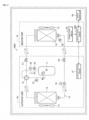
- Fig. 1 is a configuration diagram of an air-conditioner 100 according to a first embodiment.
- Fig. 1 the direction of flow of refrigerant during heating operation is indicated by solid lines.
- the direction of flow of refrigerant during cooling operation is indicated by dashed lines.
- the air-conditioner 100 is an apparatus that performs air-conditioning, such as cooling and heating.
- the air-conditioner 100 may be of a floor-installed type, a ceiling-embedded type, or a wall-hanging type.
- the air-conditioner 100 is provided with a refrigerant circuit 10, an outdoor fan Fo, an indoor fan Fi, and shut-off valves V1, V2.
- the air-conditioner 100 is also provided with, in addition to the above configuration, sensors 21 to 25, an outdoor control circuit 31 (controller), an indoor control circuit 32 (controller), and a remote controller Re.
- the refrigerant circuit 10 is a circuit through which refrigerant is circulated in a refrigeration cycle (heat pump cycle). As depicted in Fig. 1 , the refrigerant circuit 10 is provided with a compressor 11, a four-way valve 12, an outdoor heat exchanger 13, an expansion valve 14, and an indoor heat exchanger 15.
- the compressor 11 is an apparatus that compresses gaseous refrigerant.
- the type of the compressor 11 is not particularly limited, and various types of compressor, such as a scroll type, a piston type, a rotary type, a screw type, or a centrifugal type may be used. While omitted in Fig. 1 , an accumulator (gas-liquid separator) is disposed on the suction side of the compressor 11.
- the outdoor heat exchanger 13 is a heat exchanger for exchanging heat between the refrigerant flowing through a heat transfer pipe therein (not depicted) and external air delivered from the outdoor fan Fo.
- the outdoor fan Fo is a fan that delivers external air to the outdoor heat exchanger 13, and is installed in the vicinity of the outdoor heat exchanger 13.
- the indoor heat exchanger 15 is a heat exchanger that exchanges heat between the refrigerant flowing through a heat transfer pipe therein (not depicted) and the indoor air (air in a space to be air-conditioned) delivered from the indoor fan Fi.
- the indoor fan Fi is a fan that delivers the indoor air to the indoor heat exchanger 15, and is installed in the vicinity of the indoor heat exchanger 15.
- the expansion valve 14 has the function of decompressing the refrigerant that has been condensed by a "condenser” (one of the outdoor heat exchanger 13 and the indoor heat exchanger 15).
- the refrigerant that has been decompressed by the expansion valve 14 is guided to an "evaporator" (the other of the outdoor heat exchanger 13 and the indoor heat exchanger 15).
- the four-way valve 12 is a valve that switches the flow passageway of refrigerant in accordance with the operation mode of the air-conditioner 100. For example, during cooling operation (see the dashed line arrows in Fig. 1 ), the refrigerant is circulated in a refrigeration cycle in the refrigerant circuit 10 in which the compressor 11, the outdoor heat exchanger 13 (condenser), the expansion valve 14, and the indoor heat exchanger 15 (evaporator) are connected annularly successively via the four-way valve 12.
- the refrigerant is circulated in a refrigeration cycle in the refrigerant circuit 10 in which the compressor 11, the indoor heat exchanger 15 (condenser), the expansion valve 14, and the outdoor heat exchanger 13 (evaporator) are annularly successively connected via the four-way valve 12.
- the refrigerant is circulated in a refrigeration cycle through the compressor 11, the "condenser", the expansion valve 14, and the "evaporator” successively.
- the compressor 11, the four-way valve 12, the outdoor heat exchanger 13, the expansion valve 14, the outdoor fan Fo and the like are disposed in the outdoor unit Ho. Meanwhile, the indoor heat exchanger 15, the indoor fan Fi and the like are disposed in the indoor unit Hi.
- the shut-off valves V1, V2 are valves that are opened after the air-conditioner 100 has been installed, to allow the refrigerant that has been sealed in the outdoor unit Ho to be delivered throughout the refrigerant circuit 10.
- the discharge pressure sensor 21 is a sensor that detects the pressure (discharge pressure) of the refrigerant discharged from the compressor 11, and is installed in the vicinity of a discharge opening of the compressor 11.
- the discharge temperature sensor 22 is a sensor that detects the temperature (discharge temperature) of the refrigerant discharged from the compressor 11, and is installed in the vicinity of the discharge opening of the compressor 11.
- the suction pressure sensor 23 is a sensor that detects the pressure (suction pressure) of the refrigerant suctioned into the compressor 11, and is installed in the vicinity of a suction opening of the compressor 11.
- the suction temperature sensor 24 is a sensor that detects the temperature (suction temperature) of the refrigerant suctioned into the compressor 11, and is installed in the vicinity of the suction opening of the compressor 11.
- the values detected by the discharge pressure sensor 21, the discharge temperature sensor 22, the suction pressure sensor 23, and the suction temperature sensor 24 are output to the outdoor control circuit 31.
- the refrigerant leak sensor 25 is a sensor that senses a leak of refrigerant in the refrigerant circuit 10, and is installed at a predetermined location where it is easy to sense a leak of refrigerant.
- the refrigerant leak sensor 25 may be of various types, such as a semiconductor type, an infrared type, a catalytic combustion type, or an electrochemical type.
- the refrigerant leak sensor 25 When the indoor unit Hi is of floor-installed type, the refrigerant leak sensor 25 is often installed on a bottom plate (not depicted) of the indoor unit Hi. For example, if the refrigerant has leaked from a connection portion of the heat transfer pipe (not depicted) of the indoor heat exchanger 15, gaseous refrigerant settles and collects at the bottom because the refrigerant has a greater specific gravity than air. If the concentration of the refrigerant that the refrigerant leak sensor 25 has detected is more than or equal to a predetermined threshold value, the refrigerant leak sensor 25 senses a refrigerant leak and outputs a refrigerant leak sense signal to the indoor control circuit 32.
- the outdoor control circuit 31 is a microcomputer, for example, and includes, while not depicted, electronic circuits of, e.g., a central processing unit (CPU: not depicted), a read only memory (ROM), a random access memory (RAM), and various interfaces. A program stored in the ROM is read and loaded to the RAM, and the CPU performs various processes.
- the outdoor control circuit 31, based on the values detected by the sensor 21 to 24, for example, controls the compressor 11, the expansion valve 14, the outdoor fan Fo and the like.
- the indoor control circuit 32 is a microcomputer, for example, and is connected to the outdoor control circuit 31 via a communication line (the dashed and single-dotted line arrow).
- the indoor control circuit 32 controls the indoor fan Fi and the like based on information received from the outdoor control circuit 31 and signals from the remote controller Re.
- the remote controller Re is operated by a user and transmits a predetermined infrared signal to the indoor unit Hi. For example, command signals relating to operation/stoppage, a change in setting temperature, timer setting, an operation mode change request and the like are transmitted from the remote controller Re to the indoor unit Hi. Upon sensing by the refrigerant leak sensor 25 of a refrigerant leak, the relevant information is transmitted from the indoor unit Hi to the remote controller Re, and further displayed on the remote controller Re.
- the remote controller Re may include a central remote controller used in variable refrigerant flow (VRF) systems, packaged air conditioning (PAC) systems and the like.
- VRF variable refrigerant flow
- PAC packaged air conditioning
- Fig. 2 is a functional block diagram including the indoor control circuit 32 of the air-conditioner 100.
- the indoor control circuit 32 is provided with a communication portion 321, a controller 322, and a storage 323.
- the communication portion 321 provides an interface for acquiring signals from the refrigerant leak sensor 25 and exchanging predetermined data with the outdoor control circuit 31.
- the controller 322 has the function of controlling the indoor fan Fi and the like based on whether the refrigerant sealed in the refrigerant circuit 10 is flammable. As depicted in Fig. 2 , the controller 322 is provided with a data acquisition portion 322a, a refrigerant type identification portion 322b, and an operation controller 322c.
- the data acquisition portion 322a acquires, via the communication portion 321, predetermined data from the refrigerant leak sensor 25 and the outdoor control circuit 31, for example.
- the data acquired by the data acquisition portion 322a are stored in the storage 323.
- the refrigerant type identification portion 322b identifies the type of the refrigerant sealed in the refrigerant circuit 10 based on, for example, the degree of superheat of the refrigerant on the suction side/discharge side of the compressor 11 (see Fig. 1 ). The process performed by the refrigerant type identification portion 322b will be described later.
- the operation controller 322c controls the indoor fan Fi and the like based on a predetermined program.
- the data acquired by the data acquisition portion 322a are temporarily stored.
- a target value of discharge superheat degree and refrigerant physical property data (data used for calculating a condensation temperature and an evaporation temperature), which will be described later, are associated with the type of refrigerant (such as refrigerant R410A and refrigerant R32) and stored in advance.
- the refrigerant R410A is an HFC-type mixed refrigerant which is a mixture of refrigerant R32 and refrigerant R125.
- the refrigerant R410A has the characteristic of having a relatively high vapor pressure, and making it possible to achieve an increase in refrigeration cycle efficiency easily.
- the refrigerant R32 is an HFC-type single refrigerant.
- the refrigerant R32 has the characteristic of having a lower global warming potential (GWP) than refrigerant R410A, and making it possible to contribute to suppression of global warming.
- GWP global warming potential
- the refrigerant R32 is flammable (mildly flammable)
- the refrigerant R410A is nonflammable.
- the difference in refrigerant physical property is taken into consideration in implementing a control in case of a refrigerant leak.
- the predetermined threshold value (threshold value of the concentration of the refrigerant) as a reference in determining whether a refrigerant leak is sensed by the refrigerant leak sensor 25 may be set to different values depending on the type of refrigerant. For example, when the refrigerant sealed in the refrigerant circuit 10 is flammable, the controller 322 sets the predetermined threshold value (threshold value of the concentration of the refrigerant) to a value smaller than when the refrigerant sealed in the refrigerant circuit 10 is nonflammable. In this way, it becomes possible to sense a leak of flammable refrigerant with high sensitivity. In addition, no matter whether the refrigerant R410A or the refrigerant R32 is sealed in the refrigerant circuit 10, it becomes possible to sense a leak of refrigerant appropriately using a single refrigerant leak sensor 25.
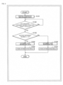
- Fig. 3 is a flowchart of a process during a test operation of the air-conditioner 100 (see Fig. 1 and Fig. 2 , as appropriate,).
- test operation refers to an operation that is performed on a trial basis prior to a normal air-conditioning operation after the air-conditioner 100 has been installed. It is assumed that in the refrigerant circuit 10 of the air-conditioner 100, the refrigerant R410A or the refrigerant R32 is sealed (either one of the refrigerants may be sealed).
- step S101 the controller 322 controls the compressor 11 and the expansion valve 14, as appropriate, using the operation controller 322c.
- the controller 322 based on a target value Kd1 of the degree of superheat of the refrigerant on the discharge side of the compressor 11, sets control command values for the compressor 11 and the expansion valve 14, and performs a test operation of the air-conditioner 100.
- the “degree of superheat” refers to a numerical value that indicates by how many degrees the actual temperature of refrigerant is higher than the saturation temperature of refrigerant with respect to a pressure.
- the degree of superheat of the refrigerant on the discharge side of the compressor 11 is referred to as a "discharge superheat degree”.
- the degree of superheat of the refrigerant on the suction side of the compressor 11 is referred to as a "suction superheat degree”.
- the target value of the discharge superheat degree Kd1 during a test operation is set in advance based on the physical property of refrigerant R410A or refrigerant R32.
- step S102 the controller 322 determines whether the discharge superheat degree Kd at the current point in time has reached the predetermined target value Kd1. For example, the controller 322 calculates, based on the physical property of refrigerant R410A, a condensation temperature corresponding to a detected value from the discharge pressure sensor 21. Further, the controller 322 subtracts the condensation temperature from a detected value from the discharge temperature sensor 22, thereby calculating the discharge superheat degree Kd of refrigerant at the current point in time. That is, the controller 322 calculates the discharge superheat degree Kd when it is assumed in this case that refrigerant R410A is sealed in the refrigerant circuit 10. The controller 322 then determines whether the discharge superheat degree Kd at the current point in time has reached the predetermined target value Kd1 (the target value Kd1 corresponding to refrigerant R410A).
- step S102 if the discharge superheat degree Kd has reached the target value Kd1 (S102: Yes), the process of the controller 322 proceeds to step S103. On the other hand, if the discharge superheat degree Kd has not reached the target value Kd1 (S102: No), the controller 322 repeats the process of step S102.
- the controller 322 determines whether a suction superheat degree Ki is higher than a predetermined threshold value Ki1, using the refrigerant type identification portion 322b.
- the predetermined threshold value Ki1 is a threshold value of a suction superheat degree as a reference for determining the type of refrigerant, and is set in advance.
- the controller 322 based on the physical property of refrigerant R410A, determines an evaporation temperature corresponding to a detected value from the suction pressure sensor 23. Further, the controller 322 subtracts the evaporation temperature from a detected value from the suction temperature sensor 24, thereby calculating the suction superheat degree Ki of refrigerant at the current point in time. The controller 322 then compares the magnitudes of the suction superheat degree Ki and the predetermined threshold value Ki1.
- step S103 if the suction superheat degree Ki is higher than the predetermined threshold value Ki1 (S103: Yes), the process of the controller 322 proceeds to step S104.
- step S104 the controller 322 determines that the refrigerant sealed in the refrigerant circuit 10 is refrigerant R410A. This is because refrigerant R410A is more likely to become a superheated vapor than refrigerant R32 is. Thus, the controller 322 identifies the type of the refrigerant sealed in the refrigerant circuit 10 based on the degree of superheat of the refrigerant on the suction side/discharge side of the compressor 11.
- step S105 the controller 322 stores the result of determination in step S104. That is, the controller 322 stores in the storage 323 information that the refrigerant actually sealed in the refrigerant circuit 10 is refrigerant R410A.
- step S103 the suction superheat degree Ki is smaller than or equal to the predetermined threshold value Ki1 (S103: No)
- the process of the controller 322 proceeds to step S106.
- step S106 the controller 322 determines that the refrigerant sealed in the refrigerant circuit 10 is refrigerant R32. This is because refrigerant R32 is less likely to become a superheated vapor (more likely to remain in a gas-liquid two-phase state) than refrigerant R410A.
- step S107 the controller 322 stores the result of the determination of step S106. That is, the controller 322 stores in the storage 323 information that the refrigerant actually sealed in the refrigerant circuit 10 is refrigerant R32.
- the controller 322 ends the process for the test operation (END).
- the controller 322 may calculate the discharge superheat degree Kd and the suction superheat degree Ki (S102, S103) based on predetermined physical property information that lies somewhere between those of refrigerant R410A and refrigerant R32.
- the series of processes depicted in Fig. 3 may be performed by the outdoor control circuit 31 (see Fig. 1 ).
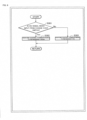
- Fig. 4 is a flowchart when an air-conditioning operation of the air-conditioner 100 is not being performed (see Fig. 1 and Fig. 2 , as appropriate).
- step S201 the controller 322 determines whether there is a refrigerant leak. That is, the controller 322 determines whether a leak of refrigerant in the refrigerant circuit 10 has been sensed by the refrigerant leak sensor 25.
- step S201 if there is no refrigerant leak (S201: No), the process of the controller 322 returns (RETURN) to "START". On the other hand, if there is a refrigerant leak in step S201 (S201: Yes), the process of the controller 322 proceeds to step S202.
- step S202 the controller 322 determines whether the refrigerant sealed in the refrigerant circuit 10 is flammable. That is, the controller 322, based on the result of processing (S104 or S106 in Fig. 3 ) during the test operation, determines whether the refrigerant sealed in the refrigerant circuit 10 is flammable.
- step S202 if the refrigerant sealed in the refrigerant circuit 10 is flammable (S202: Yes), the process of the controller 322 proceeds to step S203. That is, if it is determined that, of refrigerant R410A and refrigerant R32, the flammable refrigerant R32 is sealed in the refrigerant circuit 10, the process of the controller 322 proceeds to step S203.
- step S203 the controller 322 causes the indoor fan Fi to be driven, and further issues an alert of the refrigerant leak.
- the controller 322 causes the indoor fan Fi to be driven, whereby the flammable refrigerant that has leaked from the refrigerant circuit 10 is dispersed (agitated). That is, it becomes possible, in the space to be air-conditioned, to suppress a localized increase in the concentration of refrigerant and to increase the reliability of the air-conditioner 100.
- the controller 322 causes the remote controller Re or the like to display the fact that a refrigerant leak has occurred, thus making it possible to alert the user that the refrigerant has leaked from the refrigerant circuit 10.
- the "alert" of a refrigerant leak may be issued in the form of an audible warning that a refrigerant leak has occurred, for example.
- step S202 if the refrigerant sealed in the refrigerant circuit 10 is not flammable (S202: No), the process of the controller 322 proceeds to step S204. That is, if it is determined that, of refrigerant R410A and refrigerant R32, the nonflammable refrigerant R410A is sealed in the refrigerant circuit 10, the process of the controller 322 proceeds to step S204.
- step S204 the controller 322 issues an alert of the refrigerant leak. That is, when a leak of refrigerant has been sensed by the refrigerant leak sensor 25 (S201: Yes), the controller 322, if the refrigerant sealed in the refrigerant circuit 10 is nonflammable (S202: No), issues an alert of a leak of refrigerant (S204) without causing the indoor fan Fi to be driven.
- step S203 the process of the controller 322 returns (RETURN) to "START". In this way, the controller 322 repeats the series of processes depicted in Fig. 4 .
- the controller 322 causes the indoor fan Fi to be driven, and further issues an alert of the refrigerant leak (S203). In this way, it is possible to suppress a localized increase in the concentration of refrigerant in the space to be air-conditioned, and to alert the user about the occurrence of a refrigerant leak.
- the controller 322 issues an alert of the refrigerant leak (S204) without causing the indoor fan Fi to be driven.
- S204 the refrigerant leak
- the air-conditioner 100 which performs an appropriate control in the event of a leak of refrigerant.
- a control in accordance with the type of the refrigerant sealed in the refrigerant circuit 10 is performed by the controller 32.
- the indoor unit Hi of the same model can be commonly used. Accordingly, the manufacturing cost for mass-producing the air-conditioner 100 can be reduced compared to before. Further, when the refrigerant R410A sealed in the refrigerant circuit 10 is replaced with refrigerant R32, for example, it is not necessary to exchange the indoor unit Hi, and the cost on the user side can also be reduced.
- a second embodiment differs from the first embodiment in that the type of refrigerant is identified by the operation of a change-over switch 41 (see Fig. 5 ).
- the second embodiment is similar in other respects (such as the configuration of the refrigerant circuit 10 and the presumed use of refrigerant R410A or refrigerant R32). Accordingly, the portions different from those of the first embodiment will be described, while description of redundant portions will be omitted.
- Fig. 5 is a configuration diagram of an air-conditioner 100A according to the second embodiment.
- the air-conditioner 100A depicted in Fig. 5 is provided with the change-over switch 41 (change-over portion), in addition to the configuration (see Fig. 1 ) described with reference to the first embodiment.
- the change-over switch 41 is a switch for a change-over operation to be performed by a user (such as a worker during installation) to cause a signal indicating the type of the refrigerant sealed in the refrigerant circuit 10 to be output to an indoor control circuit 32A (controller).
- the change-over switch 41 is installed at a predetermined location in the indoor unit Hi, for example, and is changed over by an operation performed by the user.
- the change-over switch 41 is changed over to on-state by the user, and an on-signal is output from the change-over switch 41 to the indoor control circuit 32A.
- the change-over switch 41 is changed over to off-state by the user, and an off-signal is output from the change-over switch 41 to the indoor control circuit 32A.
- the indoor control circuit 32A based on the signal input from the change-over switch 41, controls the indoor fan Fi. The process of the indoor control circuit 32A will be described with reference to Fig. 6 .
- Fig. 6 is a flowchart of the process performed by the indoor control circuit 32A.
- Fig. 6 The process of Fig. 6 is performed after the test operation of the air-conditioner 100 has been completed. During the test operation, the user (worker) operates the change-over switch 41 appropriately based on the type of refrigerant actually sealed in the refrigerant circuit 10.
- step S301 the indoor control circuit 32A determines whether an on-signal is being input from the change-over switch 41. If an on-signal is being input from the change-over switch 41 (S301: Yes), the process of the indoor control circuit 32A proceeds to step S302.
- step S302 the indoor control circuit 32A, based on the on-signal input from the change-over switch 41, performs a control corresponding to the nonflammable refrigerant R410A. For example, if a leak of refrigerant has been sensed by the refrigerant leak sensor 25 during stoppage of an air-conditioning operation, the indoor control circuit 32A issues an alert of a leak of refrigerant without causing the indoor fan Fi to be driven.
- step S301 if an off-signal is being input from the change-over switch 41 (S301: No), the process of the indoor control circuit 32A proceeds to step S303.
- step S303 the indoor control circuit 32A, based on the off-signal input from the change-over switch 41, performs a control corresponding to the flammable refrigerant R32. For example, if a leak of refrigerant has been sensed by the refrigerant leak sensor 25 during stoppage of an air-conditioning operation, the indoor control circuit 32A causes the indoor fan Fi to be driven, and further issues an alert of a leak of refrigerant.
- step S302 or step S303 the process of the indoor control circuit 32A returns (RETURN) to "START". In this way, the indoor control circuit 32A repeats the series of processes depicted in Fig. 6 .
- a predetermined threshold value (threshold value of the concentration of refrigerant) as a reference in determining whether a leak of refrigerant is sensed by the refrigerant leak sensor 25 may be set by the indoor control circuit 32A as follows. That is, the indoor control circuit 32A sets the predetermined threshold value (threshold value of the concentration of refrigerant) when the refrigerant sealed in the refrigerant circuit 10 is flammable to a value smaller than when the refrigerant is nonflammable. In this way, it is possible to sense a leak of flammable refrigerant with high sensitivity, for example.
- the indoor control circuit 32A based on the signal input from the change-over switch 41, it is possible for the indoor control circuit 32A to perform a control suitable for the type of the refrigerant sealed in the refrigerant circuit 10 (refrigerant R410A or refrigerant R32).
- the first embodiment has been described with reference to the process (see Fig. 3 ) in which, based on the degree of superheat on the discharge side/suction side of the compressor 11, the controller 322 identifies the type of the refrigerant sealed in the refrigerant circuit 10.
- the type of the refrigerant sealed in the refrigerant circuit 10 may be identified using other well-known methods based on the physical property and the like of the refrigerant.
- the first embodiment has been described with reference to the configuration in which the controller 322 (see Fig. 2 ) identifies the type of refrigerant.
- the second embodiment has been described with reference to the configuration in which the change-over switch 41 (see Fig. 5 ) outputs a sg indicating the type of refrigerant.
- the outdoor control circuit 31 may transmit data indicating the form of the outdoor unit Ho to the indoor control circuit 32. This is because the type of the refrigerant sealed in the refrigerant circuit 10 is often uniquely identified by the form of the outdoor unit Ho. Then, the indoor control circuit 32 performs a control in the event of a refrigerant leak appropriately, based on the data (corresponding to the type of refrigerant) indicating the type of the outdoor unit Ho.
- refrigerant R410A and refrigerant R32 are used in the air-conditioner 100.
- this is not a limitation.
- a manager may select any two types of refrigerant from various refrigerants, such as HFC-type refrigerants, HCFC-type refrigerants, and natural refrigerants.
- the HFC-type refrigerants may include, in addition to refrigerant R410A and refrigerant R32, refrigerant R125, refrigerant R134a, refrigerant R152a, refrigerant R404A, and refrigerant R407C.
- the HCFC-type refrigerants may include refrigerant R22, refrigerant R123, refrigerant R141b, refrigerant R142b, and refrigerant R225.
- the natural refrigerant may include carbon dioxide, hydrocarbon, and water.
- the first embodiment has been described with reference to the process (S204) in which, if a leak of nonflammable refrigerant has been sensed (in Fig. 4 , S201: Yes, S202: No), the controller 322 issues an alert of a leak of refrigerant.
- this is not a limitation. For example, if a leak of nonflammable refrigerant has been sensed, the controller 322 may neither drive the indoor fan Fi nor issue an alert of the leak of refrigerant. If a leak of flammable refrigerant has been sensed, the controller 322 may cause the indoor fan Fi to be driven without issuing an alert of the leak of refrigerant.
- the controller 322 may identify the refrigerant sealed in the refrigerant circuit 10 from among three or more types of refrigerant, and perform a control corresponding to the identified type of refrigerant.
- the controller 322, based on information from the change-over switch 41, may identify the refrigerant sealed in the refrigerant circuit 10 from among three or more types of refrigerant, and perform a control corresponding to the identified type of refrigerant.
- the first embodiment has been described with reference to the process in which the controller 322 determines the type of the refrigerant sealed in the refrigerant circuit 10 during a test operation.
- the controller 322 may determine the type of the refrigerant sealed in the refrigerant circuit 10 during a normal air-conditioning operation.
- the embodiments have been described with reference to the configuration in which the air-conditioner 100 (see Fig. 1 ) is provided with a single indoor unit Hi.
- the embodiments may be applied to a multi-type air-conditioner provided with a plurality of indoor units.
- the embodiments may also be applied to an integrated-type air-conditioner in which an indoor unit and an outdoor unit are integrated.
Description
- The present invention relates to an air-conditioner.
- As a countermeasure for a leak of refrigerant from a refrigerant circuit of an air-conditioner, techniques described in Patent Literatures 1 and 2 are known, for example. Specifically, Patent Literature 1 describes that, in case of a refrigerant leak, a controller causes an indoor fan to be driven and Patent Literature 2 describes that, based on occurrence of a flammable refrigerant, an indoor unit allows a user to stop the emission of a warning started at the user's discretion.
-
- Patent Literature 1:
JP-A-2016-197006 - Patent Literature 2:
EP 3 070 420 A1 - According to the technique described in Patent Literature 1, in the event that the refrigerant has leaked from a refrigerant circuit, the indoor fan is driven in any case in order to disperse the refrigerant regardless of whether the refrigerant is flammable. Patent Literature 2 discloses also an air-conditioner with the features of the preamble of claim 1. However, depending on the type of refrigerant (whether it is flammable), it may not be necessary to drive the indoor fan even in case of a refrigerant leak. It is desirable to further enhance the comfort of a user by not unnecessarily driving the indoor fan during stoppage of an air-conditioning operation.
- Accordingly, an object of the present invention is to provide an air-conditioner which performs an appropriate control in the event of a leak of refrigerant.
- In order to solve the problem, an air-conditioner according to the present invention is provided with the features of claim 1.
- According to the present invention, it is possible to provide an air-conditioner which performs an appropriate control in the event of a leak of refrigerant.
-
-
Fig. 1 is a configuration diagram of an air-conditioner according to a first embodiment of the present invention. -
Fig. 2 is a functional block diagram including an indoor control circuit of the air-conditioner according to the first embodiment of the present invention. -
Fig. 3 is a flowchart of a process during a test operation of the air-conditioner according to the first embodiment of the present invention. -
Fig. 4 is a flowchart when an air-conditioning operation of the air-conditioner according to the first embodiment of the present invention is not being performed. -
Fig. 5 is a configuration diagram of an air-conditioner according to a second embodiment of the present invention. -
Fig. 6 is a flowchart of a process performed by a controller of the air-conditioner according to the second embodiment of the present invention. -
Fig. 1 is a configuration diagram of an air-conditioner 100 according to a first embodiment. - In
Fig. 1 , the direction of flow of refrigerant during heating operation is indicated by solid lines. The direction of flow of refrigerant during cooling operation is indicated by dashed lines. - The air-
conditioner 100 is an apparatus that performs air-conditioning, such as cooling and heating. The air-conditioner 100 may be of a floor-installed type, a ceiling-embedded type, or a wall-hanging type. - As depicted in
Fig. 1 , the air-conditioner 100 is provided with arefrigerant circuit 10, an outdoor fan Fo, an indoor fan Fi, and shut-off valves V1, V2. The air-conditioner 100 is also provided with, in addition to the above configuration,sensors 21 to 25, an outdoor control circuit 31 (controller), an indoor control circuit 32 (controller), and a remote controller Re. - The
refrigerant circuit 10 is a circuit through which refrigerant is circulated in a refrigeration cycle (heat pump cycle). As depicted inFig. 1 , therefrigerant circuit 10 is provided with acompressor 11, a four-way valve 12, anoutdoor heat exchanger 13, anexpansion valve 14, and anindoor heat exchanger 15. - The
compressor 11 is an apparatus that compresses gaseous refrigerant. The type of thecompressor 11 is not particularly limited, and various types of compressor, such as a scroll type, a piston type, a rotary type, a screw type, or a centrifugal type may be used. While omitted inFig. 1 , an accumulator (gas-liquid separator) is disposed on the suction side of thecompressor 11. - The
outdoor heat exchanger 13 is a heat exchanger for exchanging heat between the refrigerant flowing through a heat transfer pipe therein (not depicted) and external air delivered from the outdoor fan Fo. - The outdoor fan Fo is a fan that delivers external air to the
outdoor heat exchanger 13, and is installed in the vicinity of theoutdoor heat exchanger 13. - The
indoor heat exchanger 15 is a heat exchanger that exchanges heat between the refrigerant flowing through a heat transfer pipe therein (not depicted) and the indoor air (air in a space to be air-conditioned) delivered from the indoor fan Fi. - The indoor fan Fi is a fan that delivers the indoor air to the
indoor heat exchanger 15, and is installed in the vicinity of theindoor heat exchanger 15. - The
expansion valve 14 has the function of decompressing the refrigerant that has been condensed by a "condenser" (one of theoutdoor heat exchanger 13 and the indoor heat exchanger 15). The refrigerant that has been decompressed by theexpansion valve 14 is guided to an "evaporator" (the other of theoutdoor heat exchanger 13 and the indoor heat exchanger 15). - The four-
way valve 12 is a valve that switches the flow passageway of refrigerant in accordance with the operation mode of the air-conditioner 100. For example, during cooling operation (see the dashed line arrows inFig. 1 ), the refrigerant is circulated in a refrigeration cycle in therefrigerant circuit 10 in which thecompressor 11, the outdoor heat exchanger 13 (condenser), theexpansion valve 14, and the indoor heat exchanger 15 (evaporator) are connected annularly successively via the four-way valve 12. - During heating operation (see the solid line arrows in
Fig. 1 ), the refrigerant is circulated in a refrigeration cycle in therefrigerant circuit 10 in which thecompressor 11, the indoor heat exchanger 15 (condenser), theexpansion valve 14, and the outdoor heat exchanger 13 (evaporator) are annularly successively connected via the four-way valve 12. Thus, in therefrigerant circuit 10, the refrigerant is circulated in a refrigeration cycle through thecompressor 11, the "condenser", theexpansion valve 14, and the "evaporator" successively. - In the example depicted in
Fig. 1 , thecompressor 11, the four-way valve 12, theoutdoor heat exchanger 13, theexpansion valve 14, the outdoor fan Fo and the like are disposed in the outdoor unit Ho. Meanwhile, theindoor heat exchanger 15, the indoor fan Fi and the like are disposed in the indoor unit Hi. - The shut-off valves V1, V2 are valves that are opened after the air-
conditioner 100 has been installed, to allow the refrigerant that has been sealed in the outdoor unit Ho to be delivered throughout therefrigerant circuit 10. - The
discharge pressure sensor 21 is a sensor that detects the pressure (discharge pressure) of the refrigerant discharged from thecompressor 11, and is installed in the vicinity of a discharge opening of thecompressor 11. - The
discharge temperature sensor 22 is a sensor that detects the temperature (discharge temperature) of the refrigerant discharged from thecompressor 11, and is installed in the vicinity of the discharge opening of thecompressor 11. - The
suction pressure sensor 23 is a sensor that detects the pressure (suction pressure) of the refrigerant suctioned into thecompressor 11, and is installed in the vicinity of a suction opening of thecompressor 11. - The
suction temperature sensor 24 is a sensor that detects the temperature (suction temperature) of the refrigerant suctioned into thecompressor 11, and is installed in the vicinity of the suction opening of thecompressor 11. - The values detected by the
discharge pressure sensor 21, thedischarge temperature sensor 22, thesuction pressure sensor 23, and thesuction temperature sensor 24 are output to theoutdoor control circuit 31. - The
refrigerant leak sensor 25 is a sensor that senses a leak of refrigerant in therefrigerant circuit 10, and is installed at a predetermined location where it is easy to sense a leak of refrigerant. Therefrigerant leak sensor 25 may be of various types, such as a semiconductor type, an infrared type, a catalytic combustion type, or an electrochemical type. - When the indoor unit Hi is of floor-installed type, the
refrigerant leak sensor 25 is often installed on a bottom plate (not depicted) of the indoor unit Hi. For example, if the refrigerant has leaked from a connection portion of the heat transfer pipe (not depicted) of theindoor heat exchanger 15, gaseous refrigerant settles and collects at the bottom because the refrigerant has a greater specific gravity than air. If the concentration of the refrigerant that therefrigerant leak sensor 25 has detected is more than or equal to a predetermined threshold value, therefrigerant leak sensor 25 senses a refrigerant leak and outputs a refrigerant leak sense signal to theindoor control circuit 32. - The
outdoor control circuit 31 is a microcomputer, for example, and includes, while not depicted, electronic circuits of, e.g., a central processing unit (CPU: not depicted), a read only memory (ROM), a random access memory (RAM), and various interfaces. A program stored in the ROM is read and loaded to the RAM, and the CPU performs various processes. Theoutdoor control circuit 31, based on the values detected by thesensor 21 to 24, for example, controls thecompressor 11, theexpansion valve 14, the outdoor fan Fo and the like. - The
indoor control circuit 32 is a microcomputer, for example, and is connected to theoutdoor control circuit 31 via a communication line (the dashed and single-dotted line arrow). Theindoor control circuit 32 controls the indoor fan Fi and the like based on information received from theoutdoor control circuit 31 and signals from the remote controller Re. - The remote controller Re is operated by a user and transmits a predetermined infrared signal to the indoor unit Hi. For example, command signals relating to operation/stoppage, a change in setting temperature, timer setting, an operation mode change request and the like are transmitted from the remote controller Re to the indoor unit Hi. Upon sensing by the
refrigerant leak sensor 25 of a refrigerant leak, the relevant information is transmitted from the indoor unit Hi to the remote controller Re, and further displayed on the remote controller Re. - The remote controller Re may include a central remote controller used in variable refrigerant flow (VRF) systems, packaged air conditioning (PAC) systems and the like.
-
Fig. 2 is a functional block diagram including theindoor control circuit 32 of the air-conditioner 100. - As depicted in
Fig. 2 , theindoor control circuit 32 is provided with acommunication portion 321, acontroller 322, and astorage 323. - The
communication portion 321 provides an interface for acquiring signals from therefrigerant leak sensor 25 and exchanging predetermined data with theoutdoor control circuit 31. - The
controller 322 has the function of controlling the indoor fan Fi and the like based on whether the refrigerant sealed in therefrigerant circuit 10 is flammable. As depicted inFig. 2 , thecontroller 322 is provided with adata acquisition portion 322a, a refrigeranttype identification portion 322b, and anoperation controller 322c. - The
data acquisition portion 322a acquires, via thecommunication portion 321, predetermined data from therefrigerant leak sensor 25 and theoutdoor control circuit 31, for example. The data acquired by thedata acquisition portion 322a are stored in thestorage 323. - The refrigerant
type identification portion 322b identifies the type of the refrigerant sealed in therefrigerant circuit 10 based on, for example, the degree of superheat of the refrigerant on the suction side/discharge side of the compressor 11 (seeFig. 1 ). The process performed by the refrigeranttype identification portion 322b will be described later. - The
operation controller 322c controls the indoor fan Fi and the like based on a predetermined program. - In the
storage 323, the data acquired by thedata acquisition portion 322a are temporarily stored. In thestorage 323, a target value of discharge superheat degree and refrigerant physical property data (data used for calculating a condensation temperature and an evaporation temperature), which will be described later, are associated with the type of refrigerant (such as refrigerant R410A and refrigerant R32) and stored in advance. - In the following, an example will be described in which one of two types of refrigerant R410A and refrigerant R32 is sealed in the refrigerant circuit 10 (see
Fig. 1 ). The refrigerant R410A is an HFC-type mixed refrigerant which is a mixture of refrigerant R32 and refrigerant R125. The refrigerant R410A has the characteristic of having a relatively high vapor pressure, and making it possible to achieve an increase in refrigeration cycle efficiency easily. - On the other hand, the refrigerant R32 is an HFC-type single refrigerant. The refrigerant R32 has the characteristic of having a lower global warming potential (GWP) than refrigerant R410A, and making it possible to contribute to suppression of global warming.
- While the refrigerant R32 is flammable (mildly flammable), the refrigerant R410A is nonflammable. In the present embodiment, the difference in refrigerant physical property (flammable/nonflammable) is taken into consideration in implementing a control in case of a refrigerant leak.
- The predetermined threshold value (threshold value of the concentration of the refrigerant) as a reference in determining whether a refrigerant leak is sensed by the
refrigerant leak sensor 25 may be set to different values depending on the type of refrigerant. For example, when the refrigerant sealed in therefrigerant circuit 10 is flammable, thecontroller 322 sets the predetermined threshold value (threshold value of the concentration of the refrigerant) to a value smaller than when the refrigerant sealed in therefrigerant circuit 10 is nonflammable. In this way, it becomes possible to sense a leak of flammable refrigerant with high sensitivity. In addition, no matter whether the refrigerant R410A or the refrigerant R32 is sealed in therefrigerant circuit 10, it becomes possible to sense a leak of refrigerant appropriately using a singlerefrigerant leak sensor 25. -
Fig. 3 is a flowchart of a process during a test operation of the air-conditioner 100 (seeFig. 1 andFig. 2 , as appropriate,). - It is assumed that the test operation of the air-
conditioner 100 is started at "START" inFig. 3 . The "test operation" herein refers to an operation that is performed on a trial basis prior to a normal air-conditioning operation after the air-conditioner 100 has been installed. It is assumed that in therefrigerant circuit 10 of the air-conditioner 100, the refrigerant R410A or the refrigerant R32 is sealed (either one of the refrigerants may be sealed). - In step S101, the
controller 322 controls thecompressor 11 and theexpansion valve 14, as appropriate, using theoperation controller 322c. For example, thecontroller 322, based on a target value Kd1 of the degree of superheat of the refrigerant on the discharge side of thecompressor 11, sets control command values for thecompressor 11 and theexpansion valve 14, and performs a test operation of the air-conditioner 100. - The "degree of superheat" refers to a numerical value that indicates by how many degrees the actual temperature of refrigerant is higher than the saturation temperature of refrigerant with respect to a pressure. The degree of superheat of the refrigerant on the discharge side of the
compressor 11 is referred to as a "discharge superheat degree". The degree of superheat of the refrigerant on the suction side of thecompressor 11 is referred to as a "suction superheat degree". The target value of the discharge superheat degree Kd1 during a test operation is set in advance based on the physical property of refrigerant R410A or refrigerant R32. - In step S102, the
controller 322 determines whether the discharge superheat degree Kd at the current point in time has reached the predetermined target value Kd1. For example, thecontroller 322 calculates, based on the physical property of refrigerant R410A, a condensation temperature corresponding to a detected value from thedischarge pressure sensor 21. Further, thecontroller 322 subtracts the condensation temperature from a detected value from thedischarge temperature sensor 22, thereby calculating the discharge superheat degree Kd of refrigerant at the current point in time. That is, thecontroller 322 calculates the discharge superheat degree Kd when it is assumed in this case that refrigerant R410A is sealed in therefrigerant circuit 10. Thecontroller 322 then determines whether the discharge superheat degree Kd at the current point in time has reached the predetermined target value Kd1 (the target value Kd1 corresponding to refrigerant R410A). - In step S102, if the discharge superheat degree Kd has reached the target value Kd1 (S102: Yes), the process of the
controller 322 proceeds to step S103. On the other hand, if the discharge superheat degree Kd has not reached the target value Kd1 (S102: No), thecontroller 322 repeats the process of step S102. - In step S103, the
controller 322 determines whether a suction superheat degree Ki is higher than a predetermined threshold value Ki1, using the refrigeranttype identification portion 322b. The predetermined threshold value Ki1 is a threshold value of a suction superheat degree as a reference for determining the type of refrigerant, and is set in advance. For example, thecontroller 322, based on the physical property of refrigerant R410A, determines an evaporation temperature corresponding to a detected value from thesuction pressure sensor 23. Further, thecontroller 322 subtracts the evaporation temperature from a detected value from thesuction temperature sensor 24, thereby calculating the suction superheat degree Ki of refrigerant at the current point in time. Thecontroller 322 then compares the magnitudes of the suction superheat degree Ki and the predetermined threshold value Ki1. - In step S103, if the suction superheat degree Ki is higher than the predetermined threshold value Ki1 (S103: Yes), the process of the
controller 322 proceeds to step S104. - In step S104, the
controller 322 determines that the refrigerant sealed in therefrigerant circuit 10 is refrigerant R410A. This is because refrigerant R410A is more likely to become a superheated vapor than refrigerant R32 is. Thus, thecontroller 322 identifies the type of the refrigerant sealed in therefrigerant circuit 10 based on the degree of superheat of the refrigerant on the suction side/discharge side of thecompressor 11. - In step S105, the
controller 322 stores the result of determination in step S104. That is, thecontroller 322 stores in thestorage 323 information that the refrigerant actually sealed in therefrigerant circuit 10 is refrigerant R410A. - On the other hand, if in step S103 the suction superheat degree Ki is smaller than or equal to the predetermined threshold value Ki1 (S103: No), the process of the
controller 322 proceeds to step S106. - In step S106, the
controller 322 determines that the refrigerant sealed in therefrigerant circuit 10 is refrigerant R32. This is because refrigerant R32 is less likely to become a superheated vapor (more likely to remain in a gas-liquid two-phase state) than refrigerant R410A. - In step S107, the
controller 322 stores the result of the determination of step S106. That is, thecontroller 322 stores in thestorage 323 information that the refrigerant actually sealed in therefrigerant circuit 10 is refrigerant R32. - Prior to the test operation, it is not clear on the
controller 322 side which of refrigerant R410A and refrigerant R32 is sealed in therefrigerant circuit 10. Accordingly, when refrigerant R32 is actually sealed in therefrigerant circuit 10, for example, there is the possibility that the physical property of refrigerant R410A information might be used when calculating the discharge superheat degree Kd in step S102 and the suction superheat degree Ki in step S103. - In order to prevent an erroneous determination in the processes of steps S104 and S106 even in such a case, the target value Kd1 (S102) and the predetermined threshold value Ki1 (S103) are set appropriately. After the process of step S105 or step S107 has been performed, the
controller 322 ends the process for the test operation (END). - The
controller 322 may calculate the discharge superheat degree Kd and the suction superheat degree Ki (S102, S103) based on predetermined physical property information that lies somewhere between those of refrigerant R410A and refrigerant R32. The series of processes depicted inFig. 3 may be performed by the outdoor control circuit 31 (seeFig. 1 ). -
Fig. 4 is a flowchart when an air-conditioning operation of the air-conditioner 100 is not being performed (seeFig. 1 andFig. 2 , as appropriate). - It is assumed that at "START" in
Fig. 4 , the test operation of the air-conditioner 100 (seeFig. 3 ) has already been completed. In step S201, thecontroller 322 determines whether there is a refrigerant leak. That is, thecontroller 322 determines whether a leak of refrigerant in therefrigerant circuit 10 has been sensed by therefrigerant leak sensor 25. - In step S201, if there is no refrigerant leak (S201: No), the process of the
controller 322 returns (RETURN) to "START". On the other hand, if there is a refrigerant leak in step S201 (S201: Yes), the process of thecontroller 322 proceeds to step S202. - In step S202, the
controller 322 determines whether the refrigerant sealed in therefrigerant circuit 10 is flammable. That is, thecontroller 322, based on the result of processing (S104 or S106 inFig. 3 ) during the test operation, determines whether the refrigerant sealed in therefrigerant circuit 10 is flammable. - Data indicating that refrigerant R32 is flammable and refrigerant R410A is nonflammable (data specifying the process of step S203 or S204, as will be described later) are stored in the
storage 323 in advance. - In step S202, if the refrigerant sealed in the
refrigerant circuit 10 is flammable (S202: Yes), the process of thecontroller 322 proceeds to step S203. That is, if it is determined that, of refrigerant R410A and refrigerant R32, the flammable refrigerant R32 is sealed in therefrigerant circuit 10, the process of thecontroller 322 proceeds to step S203. - In step S203, the
controller 322 causes the indoor fan Fi to be driven, and further issues an alert of the refrigerant leak. Thus, even when an air-conditioning operation is not being performed, thecontroller 322 causes the indoor fan Fi to be driven, whereby the flammable refrigerant that has leaked from therefrigerant circuit 10 is dispersed (agitated). That is, it becomes possible, in the space to be air-conditioned, to suppress a localized increase in the concentration of refrigerant and to increase the reliability of the air-conditioner 100. Further, thecontroller 322 causes the remote controller Re or the like to display the fact that a refrigerant leak has occurred, thus making it possible to alert the user that the refrigerant has leaked from therefrigerant circuit 10. The "alert" of a refrigerant leak may be issued in the form of an audible warning that a refrigerant leak has occurred, for example. - In step S202, if the refrigerant sealed in the
refrigerant circuit 10 is not flammable (S202: No), the process of thecontroller 322 proceeds to step S204. That is, if it is determined that, of refrigerant R410A and refrigerant R32, the nonflammable refrigerant R410A is sealed in therefrigerant circuit 10, the process of thecontroller 322 proceeds to step S204. - In step S204, the
controller 322 issues an alert of the refrigerant leak. That is, when a leak of refrigerant has been sensed by the refrigerant leak sensor 25 (S201: Yes), thecontroller 322, if the refrigerant sealed in therefrigerant circuit 10 is nonflammable (S202: No), issues an alert of a leak of refrigerant (S204) without causing the indoor fan Fi to be driven. - When the refrigerant that has leaked from the
refrigerant circuit 10 is nonflammable (S202: No), no particular problem would be caused if a localized increase in refrigerant concentration has occurred in the space to be air-conditioned. In addition, as thecontroller 322 does not cause the indoor fan Fi to be driven in the event of a leak of nonflammable refrigerant, the user is hardly made to feel uncomfortable (uncomfortable about the indoor fan Fi being driven despite the absence of an air-conditioning operation). Accordingly, it becomes possible to make the level of comfort and energy-saving performance of the air-conditioner higher than before. - After the process of step S203 or step S204 has been performed, the process of the
controller 322 returns (RETURN) to "START". In this way, thecontroller 322 repeats the series of processes depicted inFig. 4 . - If a leak of refrigerant has been sensed during an air-conditioning operation, gaseous refrigerant dispersed by the driving of the indoor fan Fi, regardless of whether the refrigerant is flammable or not. The control after the air-conditioning operation is later stopped is as described with reference to
Fig. 4 . - According to the present embodiment, it is possible, based on the degree of superheat of the refrigerant on the suction side/discharge side of the
compressor 11, to identify the type of the refrigerant sealed in therefrigerant circuit 10 easily. In the event of a leak of flammable refrigerant (inFig. 4 , S201: Yes, S202: Yes), thecontroller 322 causes the indoor fan Fi to be driven, and further issues an alert of the refrigerant leak (S203). In this way, it is possible to suppress a localized increase in the concentration of refrigerant in the space to be air-conditioned, and to alert the user about the occurrence of a refrigerant leak. - On the other hand, in the event of a leak of nonflammable refrigerant (in
Fig. 4 , S201: Yes, S202: No), thecontroller 322 issues an alert of the refrigerant leak (S204) without causing the indoor fan Fi to be driven. In this way, it is possible to alert the user about the occurrence of a refrigerant leak appropriately, without causing the indoor fan Fi to be driven unnecessarily. Thus, according to the present embodiment, it is possible to provide the air-conditioner 100 which performs an appropriate control in the event of a leak of refrigerant. - In addition, a control in accordance with the type of the refrigerant sealed in the
refrigerant circuit 10 is performed by thecontroller 32. Thus, no matter which of refrigerant R410A and refrigerant R32 is used, the indoor unit Hi of the same model can be commonly used. Accordingly, the manufacturing cost for mass-producing the air-conditioner 100 can be reduced compared to before. Further, when the refrigerant R410A sealed in therefrigerant circuit 10 is replaced with refrigerant R32, for example, it is not necessary to exchange the indoor unit Hi, and the cost on the user side can also be reduced. - A second embodiment differs from the first embodiment in that the type of refrigerant is identified by the operation of a change-over switch 41 (see
Fig. 5 ). The second embodiment is similar in other respects (such as the configuration of therefrigerant circuit 10 and the presumed use of refrigerant R410A or refrigerant R32). Accordingly, the portions different from those of the first embodiment will be described, while description of redundant portions will be omitted. -
Fig. 5 is a configuration diagram of an air-conditioner 100A according to the second embodiment. - The air-
conditioner 100A depicted inFig. 5 is provided with the change-over switch 41 (change-over portion), in addition to the configuration (seeFig. 1 ) described with reference to the first embodiment. The change-over switch 41 is a switch for a change-over operation to be performed by a user (such as a worker during installation) to cause a signal indicating the type of the refrigerant sealed in therefrigerant circuit 10 to be output to anindoor control circuit 32A (controller). - The change-
over switch 41 is installed at a predetermined location in the indoor unit Hi, for example, and is changed over by an operation performed by the user. In an example, when refrigerant R410A is sealed in therefrigerant circuit 10, the change-over switch 41 is changed over to on-state by the user, and an on-signal is output from the change-over switch 41 to theindoor control circuit 32A. When refrigerant R32 is sealed in therefrigerant circuit 10, the change-over switch 41 is changed over to off-state by the user, and an off-signal is output from the change-over switch 41 to theindoor control circuit 32A. - The
indoor control circuit 32A, based on the signal input from the change-over switch 41, controls the indoor fan Fi. The process of theindoor control circuit 32A will be described with reference toFig. 6 . -
Fig. 6 is a flowchart of the process performed by theindoor control circuit 32A. - The process of
Fig. 6 is performed after the test operation of the air-conditioner 100 has been completed. During the test operation, the user (worker) operates the change-over switch 41 appropriately based on the type of refrigerant actually sealed in therefrigerant circuit 10. - In step S301, the
indoor control circuit 32A determines whether an on-signal is being input from the change-over switch 41. If an on-signal is being input from the change-over switch 41 (S301: Yes), the process of theindoor control circuit 32A proceeds to step S302. - In step S302, the
indoor control circuit 32A, based on the on-signal input from the change-over switch 41, performs a control corresponding to the nonflammable refrigerant R410A. For example, if a leak of refrigerant has been sensed by therefrigerant leak sensor 25 during stoppage of an air-conditioning operation, theindoor control circuit 32A issues an alert of a leak of refrigerant without causing the indoor fan Fi to be driven. - On the other hand, in step S301, if an off-signal is being input from the change-over switch 41 (S301: No), the process of the
indoor control circuit 32A proceeds to step S303. - In step S303, the
indoor control circuit 32A, based on the off-signal input from the change-over switch 41, performs a control corresponding to the flammable refrigerant R32. For example, if a leak of refrigerant has been sensed by therefrigerant leak sensor 25 during stoppage of an air-conditioning operation, theindoor control circuit 32A causes the indoor fan Fi to be driven, and further issues an alert of a leak of refrigerant. - After the process of step S302 or step S303 has been performed, the process of the
indoor control circuit 32A returns (RETURN) to "START". In this way, theindoor control circuit 32A repeats the series of processes depicted inFig. 6 . - A predetermined threshold value (threshold value of the concentration of refrigerant) as a reference in determining whether a leak of refrigerant is sensed by the
refrigerant leak sensor 25 may be set by theindoor control circuit 32A as follows.
That is, theindoor control circuit 32A sets the predetermined threshold value (threshold value of the concentration of refrigerant) when the refrigerant sealed in therefrigerant circuit 10 is flammable to a value smaller than when the refrigerant is nonflammable. In this way, it is possible to sense a leak of flammable refrigerant with high sensitivity, for example. - According to the present embodiment, based on the signal input from the change-
over switch 41, it is possible for theindoor control circuit 32A to perform a control suitable for the type of the refrigerant sealed in the refrigerant circuit 10 (refrigerant R410A or refrigerant R32). - While the air-
conditioners - For example, the first embodiment has been described with reference to the process (see
Fig. 3 ) in which, based on the degree of superheat on the discharge side/suction side of thecompressor 11, thecontroller 322 identifies the type of the refrigerant sealed in therefrigerant circuit 10. However, this is not a limitation. That is, the type of the refrigerant sealed in therefrigerant circuit 10 may be identified using other well-known methods based on the physical property and the like of the refrigerant. - The first embodiment has been described with reference to the configuration in which the controller 322 (see
Fig. 2 ) identifies the type of refrigerant. The second embodiment has been described with reference to the configuration in which the change-over switch 41 (seeFig. 5 ) outputs a sg indicating the type of refrigerant. However, these are not limitations. For example, when the outdoor unit Ho and the indoor unit Hi have been electrically connected, theoutdoor control circuit 31 may transmit data indicating the form of the outdoor unit Ho to theindoor control circuit 32. This is because the type of the refrigerant sealed in therefrigerant circuit 10 is often uniquely identified by the form of the outdoor unit Ho. Then, theindoor control circuit 32 performs a control in the event of a refrigerant leak appropriately, based on the data (corresponding to the type of refrigerant) indicating the type of the outdoor unit Ho. - The embodiments have been described with reference to the case in which one of refrigerant R410A and refrigerant R32 is used in the air-
conditioner 100. However, this is not a limitation. For example, a manager may select any two types of refrigerant from various refrigerants, such as HFC-type refrigerants, HCFC-type refrigerants, and natural refrigerants. - The HFC-type refrigerants may include, in addition to refrigerant R410A and refrigerant R32, refrigerant R125, refrigerant R134a, refrigerant R152a, refrigerant R404A, and refrigerant R407C. The HCFC-type refrigerants may include refrigerant R22, refrigerant R123, refrigerant R141b, refrigerant R142b, and refrigerant R225. The natural refrigerant may include carbon dioxide, hydrocarbon, and water.
- The first embodiment has been described with reference to the process (S204) in which, if a leak of nonflammable refrigerant has been sensed (in
Fig. 4 , S201: Yes, S202: No), thecontroller 322 issues an alert of a leak of refrigerant. However, this is not a limitation. For example, if a leak of nonflammable refrigerant has been sensed, thecontroller 322 may neither drive the indoor fan Fi nor issue an alert of the leak of refrigerant. If a leak of flammable refrigerant has been sensed, thecontroller 322 may cause the indoor fan Fi to be driven without issuing an alert of the leak of refrigerant. - The
controller 322 may identify the refrigerant sealed in therefrigerant circuit 10 from among three or more types of refrigerant, and perform a control corresponding to the identified type of refrigerant. Thecontroller 322, based on information from the change-over switch 41, may identify the refrigerant sealed in therefrigerant circuit 10 from among three or more types of refrigerant, and perform a control corresponding to the identified type of refrigerant. - The first embodiment has been described with reference to the process in which the
controller 322 determines the type of the refrigerant sealed in therefrigerant circuit 10 during a test operation. However, this is not a limitation. For example, thecontroller 322 may determine the type of the refrigerant sealed in therefrigerant circuit 10 during a normal air-conditioning operation. - The embodiments have been described with reference to the configuration in which the air-conditioner 100 (see
Fig. 1 ) is provided with a single indoor unit Hi. However, this is not a limitation. That is, the embodiments may be applied to a multi-type air-conditioner provided with a plurality of indoor units. The embodiments may also be applied to an integrated-type air-conditioner in which an indoor unit and an outdoor unit are integrated. -
- 100, 100A
- Air-conditioner
- 10
- Refrigerant circuit
- 11
- Compressor
- 12
- Four-way valve
- 13
- Outdoor heat exchanger (condenser/evaporator)
- 14
- Expansion valve
- 15
- Indoor heat exchanger (evaporator/condenser)
- 21
- Discharge pressure sensor
- 22
- Discharge temperature sensor
- 23
- Suction pressure sensor
- 24
- Suction temperature sensor
- 25
- Refrigerant leak sensor
- 31
- Outdoor control circuit (controller)
- 32, 32A
- Indoor control circuit (controller)
- 41
- Change-over switch (change-over portion)
- 321
- Communication portion
- 322
- Controller
- 323
- Storage
- Fi
- Indoor fan
- Fo
- Outdoor fan
- Ho
- Outdoor unit
- Hi
- Indoor unit
Claims (6)
- An air-conditioner comprising:a refrigerant circuit (10) through which a refrigerant is circulated in a refrigeration cycle via a compressor (11), a condenser, an expansion valve (14), and an evaporator successively;a refrigerant leak sensor (25) which senses a leak of the refrigerant in the refrigerant circuit (10); andan indoor fan (Fi) which delivers air to an indoor heat exchanger (15) functioning as the condenser or the evaporator;the air-conditioner is characterized by comprising a controller (322) which, upon sensing a leak of the refrigerant by the refrigerant leak sensor (25), causes the indoor fan (Fi) to be driven when the refrigerant sealed in the refrigerant circuit (10) is flammable and does not cause the indoor fan (Fi) to be driven when the refrigerant sealed in the refrigerant circuit (10) is nonflammable.
- The air-conditioner according to claim 1, wherein the controller (322), upon sensing a leak of the refrigerant by the refrigerant leak sensor (25), causes the indoor fan (Fi) to be driven and further issues an alert of a leak of the refrigerant when the refrigerant sealed in the refrigerant circuit (10) is flammable.
- The air-conditioner according to claim 1, wherein the controller (322), upon sensing a leak of the refrigerant by the refrigerant leak sensor (25), issues an alert of a leak of the refrigerant without causing the indoor fan (Fi) to be driven when the refrigerant sealed in the refrigerant circuit (10) is nonflammable.
- The air-conditioner according to claim 1, wherein the controller (322) identifies a type of the refrigerant sealed in the refrigerant circuit based on a degree of superheat of the refrigerant on a suction side/discharge side of the compressor (11), and further controls the indoor fan (Fi) based on whether the refrigerant of the type is flammable.
- The air-conditioner according to claim 1, comprising a change-over portion (41) for a change-over operation to be performed by a user to cause a signal indicating the type of the refrigerant sealed in the refrigerant circuit (10) to be output to the controller (322),
wherein the controller (322), upon sensing a leak of the refrigerant by the refrigerant leak sensor (25), controls the indoor fan (Fi) based on the signal input from the change-over portion (41). - The air-conditioner according to claim 4 or 5, wherein:the refrigerant leak sensor (25) senses a leak of the refrigerant when a concentration of the refrigerant detected by the refrigerant leak sensor (25) is greater than or equal to a predetermined threshold value; andthe controller (322) sets the predetermined threshold value when the refrigerant sealed in the refrigerant circuit (10) is flammable to a value smaller than when the refrigerant sealed in the refrigerant circuit (10) is nonflammable.
Applications Claiming Priority (1)
| Application Number | Priority Date | Filing Date | Title |
|---|---|---|---|
| PCT/JP2017/041188 WO2019097620A1 (en) | 2017-11-16 | 2017-11-16 | Air conditioner |
Publications (3)
| Publication Number | Publication Date |
|---|---|
| EP3712533A1 EP3712533A1 (en) | 2020-09-23 |
| EP3712533A4 EP3712533A4 (en) | 2021-06-23 |
| EP3712533B1 true EP3712533B1 (en) | 2023-09-20 |
Family
ID=66539541
Family Applications (1)
| Application Number | Title | Priority Date | Filing Date |
|---|---|---|---|
| EP17932192.2A Active EP3712533B1 (en) | 2017-11-16 | 2017-11-16 | Air conditioner |
Country Status (5)
| Country | Link |
|---|---|
| US (1) | US11280507B2 (en) |
| EP (1) | EP3712533B1 (en) |
| JP (1) | JP6861804B2 (en) |
| CN (1) | CN110050159B (en) |
| WO (1) | WO2019097620A1 (en) |
Families Citing this family (9)
| Publication number | Priority date | Publication date | Assignee | Title |
|---|---|---|---|---|
| US11060746B2 (en) * | 2017-12-01 | 2021-07-13 | Johnson Controls Technology Company | Systems and methods for detecting and responding to refrigerant leaks in heating, ventilating, and air conditioning systems |
| US10941953B2 (en) | 2018-10-17 | 2021-03-09 | Lennox Industries Inc. | HVAC system and method of circulating flammable refrigerant |
| US10767882B2 (en) * | 2018-10-17 | 2020-09-08 | Lennox Industries Inc. | Refrigerant pump down for an HVAC system |
| WO2020217380A1 (en) * | 2019-04-25 | 2020-10-29 | 東芝キヤリア株式会社 | Indoor unit of air conditioner and air conditioner |
| WO2021044547A1 (en) * | 2019-09-04 | 2021-03-11 | ダイキン工業株式会社 | Compressor unit and refrigeration device |
| US11408624B2 (en) * | 2019-10-15 | 2022-08-09 | Carrier Corporation | Refrigerant leak detection |
| EP3875861B1 (en) * | 2020-03-06 | 2023-05-17 | Daikin Industries, Ltd. | Air-conditioner, air-conditioning system, and method for monitoring air-conditioner |
| US11512867B2 (en) | 2020-03-12 | 2022-11-29 | Johnson Controls Tyco IP Holdings LLP | Refrigerant detection and control of HVAC system |
| CN117795271A (en) * | 2021-09-24 | 2024-03-29 | 东芝开利株式会社 | Refrigeration cycle device |
Family Cites Families (23)
| Publication number | Priority date | Publication date | Assignee | Title |
|---|---|---|---|---|
| US5230223A (en) * | 1992-03-20 | 1993-07-27 | Envirosystems Corporation | Method and apparatus for efficiently controlling refrigeration and air conditioning systems |
| US5608384A (en) * | 1992-10-23 | 1997-03-04 | Sentech Corporation | Method and apparatus for monitoring for the presence of a gas |
| US6510698B2 (en) * | 1999-05-20 | 2003-01-28 | Mitsubishi Denki Kabushiki Kaisha | Refrigeration system, and method of updating and operating the same |
| AU777879B2 (en) * | 2000-09-26 | 2004-11-04 | Daikin Industries, Ltd. | Air conditioner |
| US8310829B2 (en) * | 2008-05-05 | 2012-11-13 | Carrier Corporation | Integrated computer equipment container and cooling unit |
| US8973380B2 (en) * | 2009-05-28 | 2015-03-10 | Schneider Electric It Corporation | Systems and methods for detecting refrigerant leaks in cooling systems |
| CN201652623U (en) * | 2010-04-22 | 2010-11-24 | 广东美的电器股份有限公司 | Air-conditioning outdoor machine for preventing flammable refrigerant from accumulating |
| CN103154637B (en) * | 2010-09-30 | 2015-11-25 | 三菱电机株式会社 | Aircondition |
| JP5115667B2 (en) * | 2011-01-17 | 2013-01-09 | ダイキン工業株式会社 | Air conditioner |
| CN103076360A (en) * | 2013-01-30 | 2013-05-01 | 长城汽车股份有限公司 | Test device for superheating degree and supercooling degree |
| US20140223931A1 (en) * | 2013-02-12 | 2014-08-14 | Hussmann Corporation | Control system for a refrigerated merchandiser |
| JP5812081B2 (en) | 2013-11-12 | 2015-11-11 | ダイキン工業株式会社 | Indoor unit |
| JP6099608B2 (en) * | 2014-09-25 | 2017-03-22 | 三菱電機株式会社 | Heat pump equipment |
| WO2016157538A1 (en) | 2015-04-03 | 2016-10-06 | 三菱電機株式会社 | Refrigeration cycle device |
| JP6558066B2 (en) * | 2015-05-11 | 2019-08-14 | ダイキン工業株式会社 | Air conditioning ventilation system |
| US10151663B2 (en) * | 2015-09-15 | 2018-12-11 | Emerson Climate Technologies, Inc. | Leak detector sensor systems using tag-sensitized refrigerants |
| JP6697890B2 (en) | 2016-02-08 | 2020-05-27 | 日立ジョンソンコントロールズ空調株式会社 | Unit mechanism for air conditioner and air conditioner including the same |
| WO2017163321A1 (en) * | 2016-03-23 | 2017-09-28 | 三菱電機株式会社 | Refrigeration cycle device |
| JP6876375B2 (en) * | 2016-04-18 | 2021-05-26 | ダイキン工業株式会社 | Fan drive circuit of heat pump device |
| JP2017207256A (en) * | 2016-05-20 | 2017-11-24 | 三菱重工サーマルシステムズ株式会社 | Air conditioner and control method of air conditioner |
| EP3505842B1 (en) * | 2017-12-26 | 2023-01-25 | Trane International Inc. | Retrofitting r-410a hvac products to handle flammable refrigerants |
| US10767882B2 (en) * | 2018-10-17 | 2020-09-08 | Lennox Industries Inc. | Refrigerant pump down for an HVAC system |
| US10982887B2 (en) * | 2018-11-20 | 2021-04-20 | Rheem Manufacturing Company | Expansion valve with selectable operation modes |
-
2017
- 2017-11-16 CN CN201780069153.3A patent/CN110050159B/en active Active
- 2017-11-16 US US16/479,965 patent/US11280507B2/en active Active
- 2017-11-16 WO PCT/JP2017/041188 patent/WO2019097620A1/en unknown
- 2017-11-16 EP EP17932192.2A patent/EP3712533B1/en active Active
- 2017-11-16 JP JP2019515553A patent/JP6861804B2/en active Active
Also Published As
| Publication number | Publication date |
|---|---|
| EP3712533A4 (en) | 2021-06-23 |
| JPWO2019097620A1 (en) | 2019-11-21 |
| WO2019097620A1 (en) | 2019-05-23 |
| US20190338971A1 (en) | 2019-11-07 |
| CN110050159B (en) | 2021-06-25 |
| EP3712533A1 (en) | 2020-09-23 |
| US11280507B2 (en) | 2022-03-22 |
| CN110050159A (en) | 2019-07-23 |
| JP6861804B2 (en) | 2021-04-21 |
Similar Documents
| Publication | Publication Date | Title |
|---|---|---|
| EP3712533B1 (en) | Air conditioner | |
| EP3683524B1 (en) | Refrigeration apparatus | |
| EP1762794B1 (en) | Refrigerating device | |
| EP2354724B1 (en) | Air conditioner and method for controlling air conditioner | |
| EP2535670B1 (en) | Air conditioner | |
| JPH10122711A (en) | Refrigerating cycle control device | |
| JP3852472B2 (en) | Air conditioner | |
| KR101488390B1 (en) | Method for calculating the mass of a refrigerant in air conditioning apparatus | |
| JP6697890B2 (en) | Unit mechanism for air conditioner and air conditioner including the same | |
| US11125473B2 (en) | Air conditioner | |
| EP2306122A1 (en) | Refrigerating cycle apparatus, and air conditioning apparatus | |
| CN109392304B (en) | Air conditioning system, air conditioning method and control device | |
| CN109737559B (en) | Air source heat pump, air conditioner, defrosting control method and storage medium | |
| EP3578904B1 (en) | Air conditioner | |
| JPWO2019053858A1 (en) | Refrigeration cycle device and refrigeration device | |
| CN112840164A (en) | Air conditioner, management device, and refrigerant communication pipe | |
| CN108954501B (en) | Air conditioner | |
| EP4086539A1 (en) | Air-conditioning system | |
| US20230258350A1 (en) | Method for detecting refrigerant leakage, air conditioner, and storage medium | |
| EP3663681B1 (en) | Refrigeration device | |
| JP2002162126A (en) | Air conditioner | |
| JPH11118270A (en) | Air conditioner | |
| CN113272594B (en) | Air conditioner | |
| JP6519098B2 (en) | Air conditioner | |
| WO2022249502A1 (en) | Refrigeration and air-conditioning device |
Legal Events
| Date | Code | Title | Description |
|---|---|---|---|
| STAA | Information on the status of an ep patent application or granted ep patent |
Free format text: STATUS: THE INTERNATIONAL PUBLICATION HAS BEEN MADE |
|
| PUAI | Public reference made under article 153(3) epc to a published international application that has entered the european phase |
Free format text: ORIGINAL CODE: 0009012 |
|
| STAA | Information on the status of an ep patent application or granted ep patent |
Free format text: STATUS: REQUEST FOR EXAMINATION WAS MADE |
|
| 17P | Request for examination filed |
Effective date: 20190726 |
|
| AK | Designated contracting states |
Kind code of ref document: A1 Designated state(s): AL AT BE BG CH CY CZ DE DK EE ES FI FR GB GR HR HU IE IS IT LI LT LU LV MC MK MT NL NO PL PT RO RS SE SI SK SM TR |
|
| AX | Request for extension of the european patent |
Extension state: BA ME |
|
| DAV | Request for validation of the european patent (deleted) | ||
| DAX | Request for extension of the european patent (deleted) | ||
| A4 | Supplementary search report drawn up and despatched |
Effective date: 20210521 |
|
| RIC1 | Information provided on ipc code assigned before grant |
Ipc: F24F 11/74 20180101AFI20210517BHEP Ipc: F25B 1/00 20060101ALI20210517BHEP Ipc: F25B 49/02 20060101ALI20210517BHEP Ipc: F25B 49/00 20060101ALI20210517BHEP |
|
| GRAP | Despatch of communication of intention to grant a patent |
Free format text: ORIGINAL CODE: EPIDOSNIGR1 |
|
| STAA | Information on the status of an ep patent application or granted ep patent |
Free format text: STATUS: GRANT OF PATENT IS INTENDED |
|
| INTG | Intention to grant announced |
Effective date: 20230602 |
|
| GRAS | Grant fee paid |
Free format text: ORIGINAL CODE: EPIDOSNIGR3 |
|
| GRAA | (expected) grant |
Free format text: ORIGINAL CODE: 0009210 |
|
| STAA | Information on the status of an ep patent application or granted ep patent |
Free format text: STATUS: THE PATENT HAS BEEN GRANTED |
|
| AK | Designated contracting states |
Kind code of ref document: B1 Designated state(s): AL AT BE BG CH CY CZ DE DK EE ES FI FR GB GR HR HU IE IS IT LI LT LU LV MC MK MT NL NO PL PT RO RS SE SI SK SM TR |
|
| REG | Reference to a national code |
Ref country code: GB Ref legal event code: FG4D |
|
| REG | Reference to a national code |
Ref country code: CH Ref legal event code: EP |
|
| REG | Reference to a national code |
Ref country code: DE Ref legal event code: R096 Ref document number: 602017074556 Country of ref document: DE |
|
| REG | Reference to a national code |
Ref country code: IE Ref legal event code: FG4D |
|
| REG | Reference to a national code |
Ref country code: LT Ref legal event code: MG9D |
|
| PG25 | Lapsed in a contracting state [announced via postgrant information from national office to epo] |
Ref country code: GR Free format text: LAPSE BECAUSE OF FAILURE TO SUBMIT A TRANSLATION OF THE DESCRIPTION OR TO PAY THE FEE WITHIN THE PRESCRIBED TIME-LIMIT Effective date: 20231221 |
|
| REG | Reference to a national code |
Ref country code: NL Ref legal event code: MP Effective date: 20230920 |
|
| PG25 | Lapsed in a contracting state [announced via postgrant information from national office to epo] |
Ref country code: SE Free format text: LAPSE BECAUSE OF FAILURE TO SUBMIT A TRANSLATION OF THE DESCRIPTION OR TO PAY THE FEE WITHIN THE PRESCRIBED TIME-LIMIT Effective date: 20230920 Ref country code: RS Free format text: LAPSE BECAUSE OF FAILURE TO SUBMIT A TRANSLATION OF THE DESCRIPTION OR TO PAY THE FEE WITHIN THE PRESCRIBED TIME-LIMIT Effective date: 20230920 Ref country code: NO Free format text: LAPSE BECAUSE OF FAILURE TO SUBMIT A TRANSLATION OF THE DESCRIPTION OR TO PAY THE FEE WITHIN THE PRESCRIBED TIME-LIMIT Effective date: 20231220 Ref country code: LV Free format text: LAPSE BECAUSE OF FAILURE TO SUBMIT A TRANSLATION OF THE DESCRIPTION OR TO PAY THE FEE WITHIN THE PRESCRIBED TIME-LIMIT Effective date: 20230920 Ref country code: LT Free format text: LAPSE BECAUSE OF FAILURE TO SUBMIT A TRANSLATION OF THE DESCRIPTION OR TO PAY THE FEE WITHIN THE PRESCRIBED TIME-LIMIT Effective date: 20230920 Ref country code: HR Free format text: LAPSE BECAUSE OF FAILURE TO SUBMIT A TRANSLATION OF THE DESCRIPTION OR TO PAY THE FEE WITHIN THE PRESCRIBED TIME-LIMIT Effective date: 20230920 Ref country code: GR Free format text: LAPSE BECAUSE OF FAILURE TO SUBMIT A TRANSLATION OF THE DESCRIPTION OR TO PAY THE FEE WITHIN THE PRESCRIBED TIME-LIMIT Effective date: 20231221 Ref country code: FI Free format text: LAPSE BECAUSE OF FAILURE TO SUBMIT A TRANSLATION OF THE DESCRIPTION OR TO PAY THE FEE WITHIN THE PRESCRIBED TIME-LIMIT Effective date: 20230920 |
|
| PGFP | Annual fee paid to national office [announced via postgrant information from national office to epo] |
Ref country code: FR Payment date: 20231020 Year of fee payment: 7 |
|
| REG | Reference to a national code |
Ref country code: AT Ref legal event code: MK05 Ref document number: 1613654 Country of ref document: AT Kind code of ref document: T Effective date: 20230920 |
|
| PG25 | Lapsed in a contracting state [announced via postgrant information from national office to epo] |
Ref country code: NL Free format text: LAPSE BECAUSE OF FAILURE TO SUBMIT A TRANSLATION OF THE DESCRIPTION OR TO PAY THE FEE WITHIN THE PRESCRIBED TIME-LIMIT Effective date: 20230920 |
|
| PG25 | Lapsed in a contracting state [announced via postgrant information from national office to epo] |
Ref country code: IS Free format text: LAPSE BECAUSE OF FAILURE TO SUBMIT A TRANSLATION OF THE DESCRIPTION OR TO PAY THE FEE WITHIN THE PRESCRIBED TIME-LIMIT Effective date: 20240120 |
|
| PG25 | Lapsed in a contracting state [announced via postgrant information from national office to epo] |
Ref country code: AT Free format text: LAPSE BECAUSE OF FAILURE TO SUBMIT A TRANSLATION OF THE DESCRIPTION OR TO PAY THE FEE WITHIN THE PRESCRIBED TIME-LIMIT Effective date: 20230920 |