EP3808949B1 - Mixer arrangement - Google Patents
Mixer arrangement Download PDFInfo
- Publication number
- EP3808949B1 EP3808949B1 EP20196336.0A EP20196336A EP3808949B1 EP 3808949 B1 EP3808949 B1 EP 3808949B1 EP 20196336 A EP20196336 A EP 20196336A EP 3808949 B1 EP3808949 B1 EP 3808949B1
- Authority
- EP
- European Patent Office
- Prior art keywords
- exhaust gas
- reactant
- opening
- accordance
- bottom element
- Prior art date
- Legal status (The legal status is an assumption and is not a legal conclusion. Google has not performed a legal analysis and makes no representation as to the accuracy of the status listed.)
- Active
Links
- 239000000376 reactant Substances 0.000 claims description 69
- 238000002156 mixing Methods 0.000 claims description 38
- 238000002485 combustion reaction Methods 0.000 claims description 7
- 239000007789 gas Substances 0.000 description 80
- 239000000463 material Substances 0.000 description 7
- MWUXSHHQAYIFBG-UHFFFAOYSA-N nitrogen oxide Inorganic materials O=[N] MWUXSHHQAYIFBG-UHFFFAOYSA-N 0.000 description 6
- 239000007921 spray Substances 0.000 description 6
- 238000002347 injection Methods 0.000 description 4
- 239000007924 injection Substances 0.000 description 4
- 230000002093 peripheral effect Effects 0.000 description 4
- 230000003197 catalytic effect Effects 0.000 description 3
- 230000010354 integration Effects 0.000 description 3
- 230000015572 biosynthetic process Effects 0.000 description 2
- 239000002184 metal Substances 0.000 description 2
- 239000000203 mixture Substances 0.000 description 2
- XSQUKJJJFZCRTK-UHFFFAOYSA-N Urea Chemical compound NC(N)=O XSQUKJJJFZCRTK-UHFFFAOYSA-N 0.000 description 1
- 230000006978 adaptation Effects 0.000 description 1
- 230000000712 assembly Effects 0.000 description 1
- 238000000429 assembly Methods 0.000 description 1
- 238000005452 bending Methods 0.000 description 1
- 239000004202 carbamide Substances 0.000 description 1
- 238000006555 catalytic reaction Methods 0.000 description 1
- 238000010531 catalytic reduction reaction Methods 0.000 description 1
- 239000004035 construction material Substances 0.000 description 1
- 238000001816 cooling Methods 0.000 description 1
- 238000003754 machining Methods 0.000 description 1
- 238000004519 manufacturing process Methods 0.000 description 1
- 238000000746 purification Methods 0.000 description 1
- 239000007787 solid Substances 0.000 description 1
- 239000000243 solution Substances 0.000 description 1
- 238000009834 vaporization Methods 0.000 description 1
- 230000008016 vaporization Effects 0.000 description 1
- XLYOFNOQVPJJNP-UHFFFAOYSA-N water Substances O XLYOFNOQVPJJNP-UHFFFAOYSA-N 0.000 description 1
- 238000003466 welding Methods 0.000 description 1
Images
Classifications
-
- F—MECHANICAL ENGINEERING; LIGHTING; HEATING; WEAPONS; BLASTING
- F01—MACHINES OR ENGINES IN GENERAL; ENGINE PLANTS IN GENERAL; STEAM ENGINES
- F01N—GAS-FLOW SILENCERS OR EXHAUST APPARATUS FOR MACHINES OR ENGINES IN GENERAL; GAS-FLOW SILENCERS OR EXHAUST APPARATUS FOR INTERNAL COMBUSTION ENGINES
- F01N3/00—Exhaust or silencing apparatus having means for purifying, rendering innocuous, or otherwise treating exhaust
- F01N3/08—Exhaust or silencing apparatus having means for purifying, rendering innocuous, or otherwise treating exhaust for rendering innocuous
- F01N3/10—Exhaust or silencing apparatus having means for purifying, rendering innocuous, or otherwise treating exhaust for rendering innocuous by thermal or catalytic conversion of noxious components of exhaust
- F01N3/24—Exhaust or silencing apparatus having means for purifying, rendering innocuous, or otherwise treating exhaust for rendering innocuous by thermal or catalytic conversion of noxious components of exhaust characterised by constructional aspects of converting apparatus
- F01N3/28—Construction of catalytic reactors
- F01N3/2892—Exhaust flow directors or the like, e.g. upstream of catalytic device
-
- B—PERFORMING OPERATIONS; TRANSPORTING
- B01—PHYSICAL OR CHEMICAL PROCESSES OR APPARATUS IN GENERAL
- B01F—MIXING, e.g. DISSOLVING, EMULSIFYING OR DISPERSING
- B01F25/00—Flow mixers; Mixers for falling materials, e.g. solid particles
- B01F25/40—Static mixers
- B01F25/42—Static mixers in which the mixing is affected by moving the components jointly in changing directions, e.g. in tubes provided with baffles or obstructions
- B01F25/43—Mixing tubes, e.g. wherein the material is moved in a radial or partly reversed direction
- B01F25/431—Straight mixing tubes with baffles or obstructions that do not cause substantial pressure drop; Baffles therefor
- B01F25/4315—Straight mixing tubes with baffles or obstructions that do not cause substantial pressure drop; Baffles therefor the baffles being deformed flat pieces of material
-
- F—MECHANICAL ENGINEERING; LIGHTING; HEATING; WEAPONS; BLASTING
- F01—MACHINES OR ENGINES IN GENERAL; ENGINE PLANTS IN GENERAL; STEAM ENGINES
- F01N—GAS-FLOW SILENCERS OR EXHAUST APPARATUS FOR MACHINES OR ENGINES IN GENERAL; GAS-FLOW SILENCERS OR EXHAUST APPARATUS FOR INTERNAL COMBUSTION ENGINES
- F01N3/00—Exhaust or silencing apparatus having means for purifying, rendering innocuous, or otherwise treating exhaust
- F01N3/08—Exhaust or silencing apparatus having means for purifying, rendering innocuous, or otherwise treating exhaust for rendering innocuous
- F01N3/10—Exhaust or silencing apparatus having means for purifying, rendering innocuous, or otherwise treating exhaust for rendering innocuous by thermal or catalytic conversion of noxious components of exhaust
- F01N3/18—Exhaust or silencing apparatus having means for purifying, rendering innocuous, or otherwise treating exhaust for rendering innocuous by thermal or catalytic conversion of noxious components of exhaust characterised by methods of operation; Control
- F01N3/20—Exhaust or silencing apparatus having means for purifying, rendering innocuous, or otherwise treating exhaust for rendering innocuous by thermal or catalytic conversion of noxious components of exhaust characterised by methods of operation; Control specially adapted for catalytic conversion ; Methods of operation or control of catalytic converters
- F01N3/2066—Selective catalytic reduction [SCR]
-
- F—MECHANICAL ENGINEERING; LIGHTING; HEATING; WEAPONS; BLASTING
- F01—MACHINES OR ENGINES IN GENERAL; ENGINE PLANTS IN GENERAL; STEAM ENGINES
- F01N—GAS-FLOW SILENCERS OR EXHAUST APPARATUS FOR MACHINES OR ENGINES IN GENERAL; GAS-FLOW SILENCERS OR EXHAUST APPARATUS FOR INTERNAL COMBUSTION ENGINES
- F01N2240/00—Combination or association of two or more different exhaust treating devices, or of at least one such device with an auxiliary device, not covered by indexing codes F01N2230/00 or F01N2250/00, one of the devices being
- F01N2240/20—Combination or association of two or more different exhaust treating devices, or of at least one such device with an auxiliary device, not covered by indexing codes F01N2230/00 or F01N2250/00, one of the devices being a flow director or deflector
-
- Y—GENERAL TAGGING OF NEW TECHNOLOGICAL DEVELOPMENTS; GENERAL TAGGING OF CROSS-SECTIONAL TECHNOLOGIES SPANNING OVER SEVERAL SECTIONS OF THE IPC; TECHNICAL SUBJECTS COVERED BY FORMER USPC CROSS-REFERENCE ART COLLECTIONS [XRACs] AND DIGESTS
- Y02—TECHNOLOGIES OR APPLICATIONS FOR MITIGATION OR ADAPTATION AGAINST CLIMATE CHANGE
- Y02T—CLIMATE CHANGE MITIGATION TECHNOLOGIES RELATED TO TRANSPORTATION
- Y02T10/00—Road transport of goods or passengers
- Y02T10/10—Internal combustion engine [ICE] based vehicles
- Y02T10/12—Improving ICE efficiencies
Definitions
- the present invention relates to a mixer arrangement for an exhaust system of an internal combustion engine.
- such mixer arrangements ensure that a reactant injected into the exhaust gas flow, for example a urea/water solution, is efficiently mixed with the exhaust gas, so that in a downstream catalytic converter arrangement, in particular an SCR catalytic converter arrangement, which forms a Reducing the proportion of nitrogen oxides in the exhaust gas leading catalytic reaction can take place.
- a reactant injected into the exhaust gas flow for example a urea/water solution
- a mixer arrangement which comprises an approximately cylindrical exhaust gas mixing tube.
- a base element is carried on an axial end region of the exhaust gas mixing tube, on which a reactant delivery arrangement, also generally referred to as an injector, injects the reactant into a mixing volume formed in the exhaust gas mixing tube.
- a reactant delivery arrangement also generally referred to as an injector
- injector injects the reactant into a mixing volume formed in the exhaust gas mixing tube.
- several rows of exhaust gas passage openings are formed in succession in the direction of a longitudinal axis of the tube, through which exhaust gas flowing around the exhaust gas mixing tube can enter the mixing volume and mix there with the reactant.
- Exhaust gas through-openings are also provided in a longitudinal area of the exhaust gas mixing tube that widens essentially conically radially.
- a mixer arrangement is from WO 2016/118720 A1 known.
- a swirl-generating element is formed with a cylindrical section and a truncated-cone-like and thus radially widening section adjoining it in an axial end region of the cylindrical section.
- a bottom member is supported, in which on a front side facing the exhaust flow of a a reactant input opening and radially widening reactant receiving volume is formed.
- the DE 42 03 807 A1 discloses a device for the catalytic reduction of nitrogen oxides, in which a flow guide element with a cylindrical section and an adjoining frustoconical section is arranged in the exhaust gas flow.
- this object is achieved by a mixer arrangement for an exhaust system of an internal combustion engine according to claim 1.
- the base element not only has the task of axially closing off the mixing volume provided in a swirl-generating element or of carrying the reactant input arrangement for injecting the reactant, but also provides a volume with the reactant-receiving volume into which the Reactant receiving volume open exhaust gas passages surrounding the injected reactant exhaust gas flow is generated.
- This feeding of exhaust gas into the reactant holding volume ensures that no reactant droplets deflected from the spray cone of the reactant by a flow deflection or turbulence can collect on the base element and form deposits there.
- the exhaust gas flow introduced into the reactant receiving volume ensures that all of the injected reactant reaches the area of the mixing volume and can mix there efficiently with the exhaust gas introduced equally into the mixing volume via the exhaust gas passage openings.
- the twist-generating element can be placed axially with a ring-like connection area on a receiving area on the front side of the floor element and connected to the floor element.
- a design that is structurally simple to implement and that efficiently prevents the deposit of reactant on the base element is achieved in that at least one, preferably each, exhaust gas through-duct comprises an axially open, groove-like depression provided on the front side of the base element.
- At least one, preferably each exhaust gas passage in the area between The inlet opening formed between the bottom element and the ring-like connecting area of the swirl-generating element must be open radially outwards.
- At least one exhaust gas through-channel can also comprise a hole which is open radially inward towards the reactant holding volume and passes through the base element.
- a hole can, for example, be drilled into the floor element.
- the mixing volume provided in the swirl-generating element can be designed to widen radially, starting from the base element in the direction of the opening axis.
- the formation of a swirl flow can be supported by providing at least one flow deflection element in association with at least one, preferably each, exhaust gas through-opening on the swirl-generating element.
- At least one, preferably each, flow deflection element extends in the direction away from the mixing volume, ie outwards at the swirl generation element.
- a fastening arrangement can be provided on the rear side of the floor element in order to connect a reactant input arrangement to the floor element.
- the fastening arrangement comprises a plurality of fastening openings, preferably internally threaded openings, arranged around the reactant input opening at a circumferential distance from one another and open to the rear
- the reactant input arrangement can be connected to the base element in a simple manner, for example using bolts.
- At least one fastening opening can have a greater radial distance from the opening axis than at least one other fastening opening.
- fastening openings are basically designed as openings open only to the rear of the floor element in order to avoid exhaust gas leaks
- at least one fastening opening can be provided in the area of a positioning projection of the positioning means provided on the floor element for efficient utilization of the available construction material of the floor element.
- the invention also relates to an exhaust system, comprising an exhaust gas routing component and a mixer arrangement carried on the exhaust gas routing component and having a structure according to the invention, a reactant input arrangement being arranged on the rear side of the floor element.
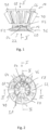
- the mixer arrangement 10 shown is essentially constructed with two components or two assemblies. On the one hand, this is a base element, generally designated 12, with which the mixer arrangement 10 is connected at an in 6 recognizable, for example hood-like component 14 of an exhaust system, generally designated 16, and on which, as in 3 1, a reactant input assembly, generally designated 18, is attached. Furthermore, the mixer arrangement 10 comprises a swirl generation element 20 which is connected to the base element 12 in the manner described below.
- the floor element 12 can be provided, for example, as a forged component, as a cast component, as a sintered component or as a metal component produced by machining.
- the twist-generating element 20 can be designed, for example, as a formed sheet metal part.
- the base element 12 has a rear side, generally designated 22, to which the reactant input arrangement 18, also generally designated as an injector, can be attached, for example with a fastening flange 24.
- An injection nozzle 26 is carried on the fastening flange 24, via which, as described below and in 3 indicated that the reactant to be injected is released in the form of a spray cone 28 .
- a reactant inlet opening 31 is formed in the base element 12, into which, for example, the injection nozzle 26 can be positioned to engage or through which the reactant to be injected is guided or injected.
- the fastening arrangement 30 can comprise, for example, a planar contact surface area 32 designed for contact with the fastening flange 24 and a plurality of fastening openings 34 arranged at a circumferential distance from one another around the reactant inlet opening 31 and designed, for example, as internally threaded openings.
- the shape of the contact surface area 32 and the positioning of the fastening openings 34 can be matched to the shape of the fastening flange 24 .
- the fastening openings 34 are at different distances from the reactant inlet opening 31 or a 3 recognizable opening axis or opening center axis A of the same.
- the base element 12 has a slightly oval peripheral contour that deviates from an essentially round peripheral contour.
- a connection region 36 is provided on the base element 12 so as to surround the fastening arrangement 30 radially on the outside.
- This connecting area 36 has a connecting flange 38 projecting radially outwards and a connecting shoulder 40 adjoining this radially inwards.
- the opening 42 formed in the exhaust gas routing component 14 can be used, for example, from the inside, so that the connecting flange 38 rests against the inside of the exhaust gas routing component 14 and the connecting shoulder 40 can be used to center the base element 12 in the opening 42 .
- the base element 12 can then be connected to the exhaust gas routing component 14 in a fixed and gas-tight manner, for example by a circumferential weld seam in the area of the connecting shoulder 40 or the connecting flange 38 .
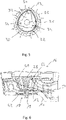
- a reactant-accommodating volume 46 is formed in the base element.
- the reactant inlet opening 31 is open to the reactant holding volume 46, and the reactant holding volume 46 has a radially expanding, for example conical, structure in the axial direction, starting from the reactant inlet opening 31, so that the reactant holding volume 46 has a smaller cross-sectional area at its area closer to the rear side 22 than at its area closer to the front side 44 .
- the base element 12 forms a receiving area 48 designed with a step, onto which the swirl-generating element 20 is placed axially with a ring-like connection area 50 and through which the swirl-generating element 20 is positioned in a radially and axially defined manner with respect to the base element 12.
- the twist-generating element 20 can be firmly connected, for example, by welding to the base element 12 in the area of the connection area 50 that overlaps the receiving area 48 or is axially supported thereon.
- the swirl-generating element 20 can be configured in its ring-like connecting region 50 to match a corresponding shape of the receiving region 48 with a substantially cylindrical structure.
- Positioning means generally designated 52 is provided.
- the positioning means 52 include, for example, where the in figure 5 recognizable fastening opening 34 is arranged at a greater distance from the reactant inlet opening 31, a positioning projection 54, which is in a 1 recognizable positioning recess 56 is positioned engagingly in the ring-like connection region 50 of the swirl-generating element 20 and thus allows only a single rotary positioning of the swirl-generating element 20 with respect to the base element 12 .
- positioning projections 54 and correspondingly also positioning recesses 56 could be provided distributed over the circumference, so that the ring-like connection area can in principle also be interrupted several times in the circumferential direction, but nevertheless still a generally ring-like overall structure for the connection of the swirl-generating element 20 to the floor element 12 provides.
- one of the fastening openings 34 is arranged in the area of such a positioning projection 54, i.e. is positioned so that it overlaps in the circumferential direction and also in the radial direction, ensures that the fastening opening 34, which is to be designed as a blind opening to avoid gas leaks, extends into the axially solid structural material of the floor element 12 can be introduced.
- a plurality of exhaust gas through-channels 58 are provided in association with the reactant-accommodating volume 46 , arranged at a distance from one another and one after the other.
- the exhaust gas passage channels 58 extend, for example, radially from the reactant inlet opening 31 to the outside radially and are basically open axially in the direction of the front side 44 due to their design as axially open, groove-like depressions.
- the essentially radially extending exhaust gas through-ducts 58 are slightly inclined in the direction of the opening axis A.
- the exhaust gas passage channels 58 are open to the outside via inlet openings 60 , that is to say to the environment with respect to the mixer arrangement 10 .
- These inlet openings 60 are between the Floor element 12 and the ring-like connection area 50 of the swirl generating element 20 is limited.
- the swirl generating element 20 provides a mixing volume 64 in its interior.
- This mixing volume 64 also has a radially widening, for example conical, structure in the axial direction, starting from the connection of the swirl-generating element 20 to the base element 12 .
- Swirl generating element 20 is provided with a plurality of exhaust gas passage openings 66 arranged at a circumferential distance from one another.
- the exhaust gas passage openings 66 can, for example, be designed or dimensioned in such a way that they each essentially extend over almost the entire axial extent of the swirl-generating element 20 and have an increasing circumferential dimension in the direction away from the base element 12, so that between immediately adjacent exhaust gas passage openings 66 Webs 68 are formed with approximately constant dimensions in the circumferential direction.
- a flap-like or wing-like flow deflection element 70 is provided in association with each exhaust gas passage opening 66 .
- These can be produced, for example, by bending the material area surrounded by this slot radially outwards when making a substantially U-shaped slot in the structural material of the swirl-generating element to create a respective exhaust gas passage opening 66, so that on the one hand a respective exhaust gas passage opening 66 is formed, and on the other hand, a flow deflection element 70 adjoining a respective web 68 is formed by this material region.
- the peripheral contour of the flow deflection elements 70 thus essentially also corresponds to the peripheral contour of the exhaust gas passage openings 66 associated with them , ie segments arranged at different angles with respect to the basic geometry of the swirl-generating element 20 can be subdivided.
- the exhaust gas passage openings 66 following one another in the circumferential direction are provided with varying circumferential distances. This means that not all exhaust gas passage openings 66 are at the same circumferential distance from the directly adjacent exhaust gas passage openings 66, with the result that webs 68 with different circumferential dimensions are present.
- the exhaust gas passage openings 66 can also be dimensioned differently from one another.
- the flow deflection elements 70 can also be dimensioned differently from one another or set or angled differently with respect to the basic geometry of the swirl-generating element 20, ie bent radially outwards to a different extent.
- the 6 illustrates the integration of a mixer assembly 10 constructed in this way into the exhaust system 16.
- the mixer arrangement 10 in the region of the swirl-generating element 20 is not evenly flown by exhaust gas in the circumferential direction and thus a fundamentally non-uniform entry characteristic of the exhaust gas into the mixing volume 64 would occur when generating a swirl flow.
- This uneven inflow is compensated for by the previously described varying positioning and/or different dimensions and/or different shapes of the exhaust gas passage openings 66 and also of the flow deflection elements 70
- An approximately concentric or almost symmetrical swirl flow can be generated when exhaust gas enters the mixing volume, so that very uniform mixing with the reactant injected into the mixing volume 64 in the form of the spray cone 28 can also be generated.
- the exhaust gas flowing onto mixer arrangement 10 from the outside not only flows into mixing volume 10 via exhaust gas passage openings 66, but also flows via inlet openings 60 and exhaust gas passage channels 58 into reactant holding volume 46 in the region in which the reactant from the Injection nozzle 26 of the reactant input arrangement 18 exits.
- an exhaust gas flow is generated in the interior of the reactant holding volume 46 which, starting from the surface of the base element 12, envelops the spray cone 28, thus forming a sheath flow.
- This sheath flow directs the reactant discharged in the form of the spray cone 28 from the reactant receiving volume into the mixing volume 64, where the primary mixing with exhaust gas then occurs.
- this exhaust gas flow introduced into the reactant holding volume 46 ensures that turbulence or backflow cannot lead to reactant droplets being deposited in the area of the surface of the base element 12, i.e. in the area of the reactant holding volume 46, on the base element 12 and there deposits can form.
- Generating such a jacket flow ensures that essentially all of the reactant that is released reaches the mixing volume 64 and is available there for mixing with the exhaust gas that is also introduced into the mixing volume 64 in the form of a swirl flow.
- the fact that the hot combustion exhaust gases flow around the base element 12 in the region of the reactant-receiving volume 46 ensures that the formation of deposits is prevented from cooling the base element 12 .
- the configuration of a mixer arrangement according to the invention ensures that with a significantly reduced risk of deposits forming due to a very uniform delivery of the reactant into the mixing volume and due to the possibility of being able to generate a very uniform turbulent flow with a structure that is essentially concentric to the opening axis A, a very efficient mixing of reactant and exhaust gas and efficient vaporization of exhaust gas can be generated, which in turn can lead to improved exhaust gas purification, especially during a cold start or at low load points in an SCR catalytic converter arrangement that follows downstream.
- the mixer arrangement shown in the figures and previously described in detail can be varied in various aspects.
- the arrangement and/or shape of the exhaust gas passage openings or the flow deflection elements can be adapted to the structure of a respective exhaust system or the flow guidance in an exhaust system can be selected differently than shown.
- the number and dimensioning of the exhaust gas through-channels can also deviate from the arrangement and dimensioning shown.
- these exhaust gas passage channels can also be provided as holes extending inside the base element, for example drilled holes, which on the one hand are open radially outwards and on the other hand are open in the area of the surface of the base element surrounding the reactant-accommodating volume to the reactant-accommodating volume.
- the shape of the exhaust gas passages is to ensure that they do not intersect with the fastening openings used to connect the reactant delivery arrangement, which ultimately means that the fastening openings on the one hand and the exhaust gas passages on the other hand are to be arranged in different circumferential areas with respect to the axis of the opening.
Landscapes
- Chemical & Material Sciences (AREA)
- Chemical Kinetics & Catalysis (AREA)
- Engineering & Computer Science (AREA)
- Health & Medical Sciences (AREA)
- Toxicology (AREA)
- Combustion & Propulsion (AREA)
- Mechanical Engineering (AREA)
- General Engineering & Computer Science (AREA)
- Dispersion Chemistry (AREA)
- Exhaust Gas After Treatment (AREA)
- Exhaust Gas Treatment By Means Of Catalyst (AREA)
Description
Die vorliegende Erfindung betrifft eine Mischeranordnung für eine Abgasanlage einer Brennkraftmaschine.The present invention relates to a mixer arrangement for an exhaust system of an internal combustion engine.
Derartige Mischeranordnungen sorgen in Abgasanlagen von insbesondere als Dieselaggregate ausgebildeten Brennkraftmaschinen dafür, dass ein in den Abgasstrom eingespritztes Reaktionsmittel, beispielsweise eine Harnstoff/WasserLösung, mit dem Abgas effizient durchmischt wird, so dass in einer stromabwärts folgenden Katalysatoranordnung, insbesondere SCR-Katalysatoranordnung, die zu einer Verringerung des Stickoxidanteils im Abgas führende katalytische Reaktion ablaufen kann.In exhaust systems of internal combustion engines designed in particular as diesel units, such mixer arrangements ensure that a reactant injected into the exhaust gas flow, for example a urea/water solution, is efficiently mixed with the exhaust gas, so that in a downstream catalytic converter arrangement, in particular an SCR catalytic converter arrangement, which forms a Reducing the proportion of nitrogen oxides in the exhaust gas leading catalytic reaction can take place.
Aus der
Eine Mischeranordnung gemäß dem Oberbegriff des Anspruchs 1 ist aus der
Die
Es ist die Aufgabe der vorliegenden Erfindung, eine Mischeranordnung für eine Abgasanlage einer Brennkraftmaschine bereitzustellen, welche bei verringerter Gefahr der Entstehung von Ablagerungen eines Reaktionsmittels ein verbessertes Mischverhalten für das eingespritzte Reaktionsmittel bereitstellt.It is the object of the present invention to provide a mixer arrangement for an exhaust system of an internal combustion engine which, with a reduced risk of deposits of a reactant forming, provides improved mixing behavior for the injected reactant.
Erfindungsgemäß wird diese Aufgabe gelöst durch eine Mischeranordnung für eine Abgasanlage einer Brennkraftmaschine gemäß Anspruch 1.According to the invention, this object is achieved by a mixer arrangement for an exhaust system of an internal combustion engine according to claim 1.
Bei der erfindungsgemäß aufgebauten Mischeranordnung hat das Bodenelement nicht nur die Aufgabe, das in einem Drallerzeugungselement bereitgestellte Mischvolumen axial abzuschließen bzw. die Reaktionsmitteleingabeanordnung zum Einspritzen des Reaktionsmittels zu tragen, sondern stellt mit dem Reaktionsmittel-Aufnahmevolumen auch ein Volumen bereit, in welches über die zu diesem Reaktionsmittel-Aufnahmevolumen offenen Abgasdurchtrittskanäle ein das eingespritzte Reaktionsmittel umgebender Abgasstrom erzeugt wird. Diese Einspeisung von Abgas in das Reaktionsmittel-Aufnahmevolumen sorgt dafür, dass keine durch eine Strömungsumlenkung oder Verwirbelungen aus dem Sprühkegel des Reaktionsmittels abgelenkten Reaktionsmitteltröpfchen sich am Bodenelement ansammeln und dort Ablagerungen bilden können. Der in das Reaktionsmittel-Aufnahmevolumen eingeleitete Abgasstrom sorgt dafür, dass das gesamte eingespritzte Reaktionsmittel in den Bereich des Mischvolumens gelangt und sich dort effizient mit dem über die Abgasdurchtrittsöffnungen gleichermaßen in das Mischvolumen eingeleiteten Abgas durchmischen kann.In the mixer arrangement constructed according to the invention, the base element not only has the task of axially closing off the mixing volume provided in a swirl-generating element or of carrying the reactant input arrangement for injecting the reactant, but also provides a volume with the reactant-receiving volume into which the Reactant receiving volume open exhaust gas passages surrounding the injected reactant exhaust gas flow is generated. This feeding of exhaust gas into the reactant holding volume ensures that no reactant droplets deflected from the spray cone of the reactant by a flow deflection or turbulence can collect on the base element and form deposits there. The exhaust gas flow introduced into the reactant receiving volume ensures that all of the injected reactant reaches the area of the mixing volume and can mix there efficiently with the exhaust gas introduced equally into the mixing volume via the exhaust gas passage openings.
Für eine feste Verbindung mit dem Bodenelement kann das Drallerzeugungselement mit einem ringartigen Verbindungsbereich auf einen Aufnahmebereich an der Vorderseite des Bodenelements axial aufgesetzt und mit dem Bodenelement verbunden sein.For a fixed connection to the floor element, the twist-generating element can be placed axially with a ring-like connection area on a receiving area on the front side of the floor element and connected to the floor element.
Eine baulich einfach zu realisierende und die Ablagerung von Reaktionsmittel auf dem Bodenelement effizient unterbindende Ausgestaltung wird dadurch erreicht, dass wenigstens ein, vorzugsweise jeder Abgasdurchtrittskanal eine an der Vorderseite des Bodenelements vorgesehene, axial offene nutartige Einsenkung umfasst.A design that is structurally simple to implement and that efficiently prevents the deposit of reactant on the base element is achieved in that at least one, preferably each, exhaust gas through-duct comprises an axially open, groove-like depression provided on the front side of the base element.
Um dabei den Eintritt von Abgas in die Abgasdurchtrittskanäle zu ermöglichen, kann wenigstens ein, vorzugsweise jeder Abgasdurchtrittskanal im Bereich einer zwischen dem Bodenelement und dem ringartigen Verbindungsbereich des Drallerzeugungselements gebildeten Eintrittsöffnung nach radial außen offen sein.In order to allow the entry of exhaust gas into the exhaust gas passages, at least one, preferably each exhaust gas passage in the area between The inlet opening formed between the bottom element and the ring-like connecting area of the swirl-generating element must be open radially outwards.
Für den Eintritt von Abgas in das im Bodenelement gebildete Reaktionsmittel-Aufnahmevolumen kann ferner wenigstens ein Abgasdurchtrittskanal ein zu dem Reaktionsmittel-Aufnahmevolumen nach radial innen offenes, das Bodenelement durchsetzendes Loch umfassen. Ein derartiges Loch kann beispielsweise als Bohrung in das Bodenelement eingebracht werden.For the entry of exhaust gas into the reactant holding volume formed in the base element, at least one exhaust gas through-channel can also comprise a hole which is open radially inward towards the reactant holding volume and passes through the base element. Such a hole can, for example, be drilled into the floor element.
Für eine effiziente Durchmischung des in das Mischvolumen gelangenden Reaktionsmittels mit in das Mischvolumen eintretendem Abgas kann das im Drallerzeugungselement bereitgestellte Mischvolumen ausgehend vom Bodenelement in Richtung der Öffnungsachse sich radial erweiternd ausgebildet sein.For efficient mixing of the reactant entering the mixing volume with the exhaust gas entering the mixing volume, the mixing volume provided in the swirl-generating element can be designed to widen radially, starting from the base element in the direction of the opening axis.
Grundsätzlich ist es vorteilhaft, für eine gleichmäßige und effiziente Durchmischung von Abgas und Reaktionsmittel eine zur Öffnungsachse, welche im Wesentlichen auch einer Längsmittenachse des Drallerzeugungselements bzw. des Mischvolumens entsprechen kann, konzentrische bzw. im Wesentlichen symmetrische Drallströmung zu erzeugen. Da, abhängig von der Integration der Mischeranordnung in den Abgasstrom, jedoch grundsätzlich nicht gewährleistet werden kann, dass das Drallerzeugungselement in allen Umfangsbereichen gleichmäßig von Abgas angeströmt wird, wird für eine eine ungleichmäßige Anströmung mit Abgas kompensierende Ausgestaltung des Drallerzeugungselements vorgeschlagen, dass wenigstens ein Teil der in Umfangsrichtung aufeinander folgenden Abgasdurchtrittsöffnungen mit zueinander unterschiedlicher Größe oder/und Form oder/und unterschiedlichem Abstand zu einer in Umfangsrichtung unmittelbar folgenden Abgasdurchtrittsöffnung ausgebildet ist.In principle, it is advantageous for uniform and efficient mixing of exhaust gas and reactant to generate a swirl flow that is concentric or essentially symmetrical to the opening axis, which can essentially also correspond to a longitudinal central axis of the swirl generating element or the mixing volume. Since, depending on the integration of the mixer arrangement in the exhaust gas flow, it cannot be guaranteed that exhaust gas flows evenly against the swirl generating element in all circumferential areas, it is proposed for a design of the swirl generating element that compensates for an uneven flow of exhaust gas that at least part of the exhaust gas passage openings that follow one another in the circumferential direction and have different sizes and/or shapes and/or different distances from an exhaust gas passage opening that follows immediately in the circumferential direction.
Die Entstehung einer Drallströmung kann dadurch unterstützt werden, dass in Zuordnung zu wenigstens einer, vorzugsweise jeder Abgasdurchtrittsöffnung am Drallerzeugungselement wenigstens ein Strömungsablenkelement vorgesehen ist.The formation of a swirl flow can be supported by providing at least one flow deflection element in association with at least one, preferably each, exhaust gas through-opening on the swirl-generating element.
Wenn dabei wenigstens zwei in Zuordnung zu verschiedenen Abgasdurchtrittsöffnungen vorgesehene Strömungsablenkelemente mit zueinander unterschiedlicher Größe oder/und Form oder/und Anstellung ausgebildet sind, kann auch dadurch eine ungleichmäßige Anströmung des Drallerzeugungselements mit Abgas kompensiert werden.If at least two flow deflection elements assigned to different exhaust gas passage openings are designed with different sizes and/or shapes and/or positions, an uneven flow of exhaust gas onto the swirl-generating element can also be compensated for.
Um im Inneren des Mischvolumens das Entstehen der Drallströmung nicht zu beeinträchtigen, wird weiter vorgeschlagen, dass wenigstens ein, vorzugsweise jedes Strömungsablenkelement sich in Richtung vom Mischvolumen weg, also am Drallerzeugungselement sich nach außen erstreckt.In order not to impair the creation of the swirl flow in the interior of the mixing volume, it is further proposed that at least one, preferably each, flow deflection element extends in the direction away from the mixing volume, ie outwards at the swirl generation element.
Insbesondere bei der vorangehend beschriebenen nicht symmetrischen Ausgestaltung des Drallerzeugungselements ist es vorteilhaft, für eine definierte Positionierung desselben im Abgasstrom Positioniermittel vorzusehen, um eine definierte Drehpositionierung des Drallerzeugungselements bezüglich des Bodenelements um die Öffnungsachse vorgeben zu können.In particular, in the afore-described non-symmetrical configuration of the swirl-generating element, it is advantageous to provide positioning means for a defined positioning of the same in the exhaust-gas flow, in order to defined rotational positioning of the swirl generating element with respect to the bottom element to be able to specify the opening axis.
Zur Anbindung einer Reaktionsmitteleingabeanordnung an das Bodenelement kann an der Rückseite des Bodenelements eine Befestigungsanordnung vorgesehen sein.A fastening arrangement can be provided on the rear side of the floor element in order to connect a reactant input arrangement to the floor element.
Wenn die Befestigungsanordnung eine Mehrzahl von um die Reaktionsmittel-Eingabeöffnung mit Umfangsabstand zueinander angeordneten und zur Rückseite offenen Befestigungsöffnungen, vorzugsweise Innengewindeöffnungen, umfasst, kann die Reaktionsmitteleingabeanordnung in einfacher Weise beispielsweise unter Einsatz von Schraubbolzen an das Bodenelement angebunden werden.If the fastening arrangement comprises a plurality of fastening openings, preferably internally threaded openings, arranged around the reactant input opening at a circumferential distance from one another and open to the rear, the reactant input arrangement can be connected to the base element in a simple manner, for example using bolts.
Um dabei eine Anpassung an die bauliche Ausgestaltung einer Reaktionsmitteleingabeanordnung erreichen zu können, kann wenigstens eine Befestigungsöffnung einen größeren Radialabstand zur Öffnungsachse aufweisen als wenigstens eine andere Befestigungsöffnung.In order to be able to achieve an adaptation to the structural design of a reactant input arrangement, at least one fastening opening can have a greater radial distance from the opening axis than at least one other fastening opening.
Da die Befestigungsöffnungen grundsätzlich als nur zur Rückseite des Bodenelements offene Öffnungen auszugestalten sind, um Abgasleckagen zu vermeiden, kann für eine effiziente Ausnutzung des zur Verfügung stehenden Aufbaumaterials des Bodenelements wenigstens eine Befestigungsöffnung im Bereich eines am Bodenelement vorgesehenen Positioniervorsprungs der Positioniermittel vorgesehen sein.Since the fastening openings are basically designed as openings open only to the rear of the floor element in order to avoid exhaust gas leaks, at least one fastening opening can be provided in the area of a positioning projection of the positioning means provided on the floor element for efficient utilization of the available construction material of the floor element.
Die Erfindung betrifft ferner eine Abgasanlage, umfassend eine Abgasführungskomponente und eine an der Abgasführungskomponente getragene Mischeranordnung mit erfindungsgemäßem Aufbau, wobei an der Rückseite des Bodenelements eine Reaktionsmitteleingabeanordnung angeordnet ist.The invention also relates to an exhaust system, comprising an exhaust gas routing component and a mixer arrangement carried on the exhaust gas routing component and having a structure according to the invention, a reactant input arrangement being arranged on the rear side of the floor element.
Die vorliegende Erfindung wird nachfolgend mit Bezug auf die beiliegenden Figuren detailliert beschrieben. Es zeigt:
- Fig. 1
- eine Seitenansicht einer Mischeranordnung für eine Abgasanordnung einer Brennkraftmaschine in Bildrichtung I in
Fig. 2 undFig. 4 ; - Fig. 2
- eine Draufsicht der Mischeranordnung der
Fig. 1 in Blickrichtung II inFig. 1 ; - Fig. 3
- eine Längsschnittansicht der Mischeranordnung der
Fig. 1 , geschnitten längs einer Linie III-III inFig. 2 ; - Fig. 4
- eine Längsschnittansicht der Mischeranordnung der
Fig. 1 , geschnitten längs einer Linie IV-IV inFig. 2 ; - Fig. 5
- eine Rückansicht der Mischeranordnung der
Fig. 1 , betrachtet in Richtung V inFig. 1 ; - Fig. 6
- eine Teilansicht einer Abgasanlage mit der in diese integrierten Mischeranordnung der
Fig. 1 .
- 1
- a side view of a mixer arrangement for an exhaust arrangement of an internal combustion engine in the image direction I in
2 and4 ; - 2
- a plan view of the mixer assembly of FIG
1 in line of sight II in1 ; - 3
- a longitudinal sectional view of the mixer assembly of FIG
1 , cut along a line III-III in2 ; - 4
- a longitudinal sectional view of the mixer assembly of FIG
1 , cut along a line IV-IV in2 ; - figure 5
- a rear view of the mixer assembly of FIG
1 , viewed in direction V in1 ; - 6
- a partial view of an exhaust system with the integrated into this mixer assembly
1 .
Die in den
Das Bodenelement 12 kann beispielsweise als geschmiedetes Bauteil, als Gussbauteil, als Sinterbauteil oder als durch spanabhebende Bearbeitung hergestelltes Metallbauteil bereitgestellt sein. Das Drallerzeugungselement 20 kann beispielsweise als Blechumformteil ausgebildet sein.The
Das Bodenelement 12 weist eine allgemein mit 22 bezeichnete Rückseite auf, an welcher die allgemein auch als Injektor bezeichnete Reaktionsmitteleingabeanordnung 18 beispielsweise mit einem Befestigungsflansch 24 angebracht werden kann. An dem Befestigungsflansch 24 ist eine Einspritzdüse 26 getragen, über welche, wie nachfolgend noch beschrieben und in
An der Rückseite 22 des Bodenelements 12 ist eine in
Die Befestigungsanordnung 30 radial außen umgebend ist am Bodenelement 12 ein Verbindungsbereich 36 vorgesehen. Dieser Verbindungsbereich 36 weist einen nach radial außen vorstehenden Verbindungsflansch 38 und radial innen an diesen anschließend eine Verbindungsschulter 40 auf. Wie in
An einer Vorderseite 44 des Bodenelements 12 ist in diesem ein Reaktionsmittel-Aufnahmevolumen 46 ausgebildet. Die Reaktionsmittel-Eingabeöffnung 31 ist zu dem Reaktionsmittel-Aufnahmevolumen 46 offen, und das Reaktionsmittel-Aufnahmevolumen 46 weist in axialer Richtung, ausgehend von der Reaktionsmittel-Eingabeöffnung 31, eine radial sich erweiternde, beispielsweise konische Struktur auf, so dass das Reaktionsmittel-Aufnahmevolumen 46 an seinem der Rückseite 22 näher liegenden Bereich eine geringere Querschnittsfläche aufweist, als an seinem der Vorderseite 44 näher liegenden Bereich.On a
Im Bereich der Vorderseite 44 bildet das Bodenelement 12 einen mit einer Stufe ausgebildeten Aufnahmebereich 48, auf welchen das Drallerzeugungselement 20 mit einem ringartigen Verbindungsbereich 50 axial aufgesetzt ist und durch welchen das Drallerzeugungselement 20 radial und axial definiert bezüglich des Bodenelements 12 positioniert ist. Das Drallerzeugungselement 20 kann beispielsweise durch Verschweißung mit dem Bodenelement 12 im Bereich des den Aufnahmebereich 48 übergreifenden bzw. daran sich axial abstützenden Verbindungsbereichs 50 fest verbunden sein. Insbesondere kann zur einfachen Herstellung der Verbindung des Drallerzeugungselements 20 mit dem Bodenelement 12 das Drallerzeugungselement 20 in seinem ringartigen Verbindungsbereich 50 angepasst an eine entsprechende Formgebung des Aufnahmebereichs 48 mit im Wesentlichen zylindrischer Struktur ausgebildet sein.In the area of the
Um auch eine definierte Drehpositionierung bzw. Umfangspositionierung des Drallerzeugungselements 20 bezüglich des Bodenelements 12 zu erhalten, sind allgemein mit 52 bezeichnete Positioniermittel vorgesehen. Die Positioniermittel 52 umfassen beispielsweise dort, wo die in
Im Bodenelement 12 sind in Zuordnung zu dem Reaktionsmittel-Aufnahmevolumen 46 mehrere in Umfangsrichtung mit Abstand zueinander und aufeinander folgend angeordnete, allgemein in sternartiger Struktur vorgesehene Abgasdurchtrittskanäle 58 vorgesehen. Die Abgasdurchtrittskanäle 58 erstrecken sich z.B. radial ausgehend von der Reaktionsmittel-Eingabeöffnung 31 bis nach radial außen und sind aufgrund ihrer Ausgestaltung als axial offene, nutartige Einsenkungen grundsätzlich axial in Richtung zur Vorderseite 44 hin offen. Entsprechend der Formgebung des Bodenelements 12 zum Bereitstellen der sich erweiternden Geometrie des Reaktionsmittel-Aufnahmevolumens 46 sind die im Wesentlichen radial sich erstreckenden Abgasdurchtrittskanäle 58 dabei in Richtung der Öffnungsachse A leicht angestellt. Radial außen sind die Abgasdurchtrittskanäle 58 über Eintrittsöffnungen 60 nach außen, also zur Umgebung bezüglich der Mischeranordnung 10, offen. Diese Eintrittsöffnungen 60 sind zwischen dem Bodenelement 12 und dem ringartigen Verbindungsbereich 50 des Drallerzeugungselements 20 begrenzt.In the
In Umfangsrichtung zwischen den Abgasdurchtrittskanälen 58 liegen Materialbereiche 62 des Bodenelements 12, welche im Wesentlichen auch die in Achsrichtung radial sich erweiternde Struktur des Reaktionsmittel-Aufnahmevolumens 46 festlegen. Die nicht im Bereich des Positioniervorsprungs 54 positionierten Befestigungsöffnungen 34, welche gleichermaßen zum Vermeiden von Gasleckagen als Sacköffnungen ausgebildet sind, können im Bereich dieser Materialbereiche 62 vorgesehen sein, also dort, wo das Bodenelement 12 eine vergleichsweise große axiale Materialdicke aufweist. Auf diese Art und Weise kann eine stabile, beispielsweise durch Verschraubung realisierte Anbindung der Reaktionsmittelabgabeanordnung 18 an das Bodenelement 12 gewährleistet werden.In the circumferential direction between the exhaust gas through-
Das Drallerzeugungselement 20 stellt in seinem Innenbereich ein Mischvolumen 64 bereit. Auch dieses Mischvolumen 64 weist in axialer Richtung, ausgehend von der Anbindung des Drallerzeugungselements 20 an das Bodenelement 12, eine radial sich erweiternde, beispielsweise konische Struktur auf. In Umfangsrichtung um die Öffnungsachse A, welche auch einer Längsmittenachse des Drallerzeugungselements 20 und im Wesentlichen auch der Haupt-Einspritzrichtung entspricht, in welcher das Reaktionsmittel in Form des Sprühkegels 28 in das Reaktionsmittel-Aufnahmevolumen 46 bzw. das Mischvolumen 64 eingespritzt wird, sind in dem Drallerzeugungselement 20 mehrere mit Umfangsabstand zueinander angeordnete Abgasdurchtrittsöffnungen 66 vorgesehen. Die Abgasdurchtrittsöffnungen 66 können beispielsweise so gestaltet bzw. dimensioniert sein, dass sie sich im Wesentlichen jeweils über nahezu die gesamte axiale Ausdehnung des Drallerzeugungselements 20 erstrecken und in Richtung vom Bodenelement 12 weg eine zunehmende Umfangsabmessung aufweisen, so dass zwischen in Umfangsrichtung einander unmittelbar benachbarten Abgasdurchtrittsöffnungen 66 Stege 68 mit näherungsweise konstanter Abmessung in Umfangsrichtung ausgebildet sind.The
In Zuordnung zu jeder Abgasdurchtrittsöffnung 66 ist ein klappen- oder flügelartiges Strömungsablenkelement 70 vorgesehen. Diese können beispielsweise dadurch erzeugt werden, dass beim Einbringen eines im Wesentlichen U-förmigen Schlitzes in das Aufbaumaterial des Drallerzeugungselements zum Erzeugen einer jeweiligen Abgasdurchtrittsöffnung 66 der von diesem Schlitz umgebene Materialbereich nach radial außen abgebogen wird, so dass einerseits eine jeweilige Abgasdurchtrittsöffnung 66 entsteht, und andererseits durch diesen Materialbereich ein an einen jeweiligen Steg 68 anschließendes Strömungsablenkelement 70 entsteht. Die Umfangskontur der Strömungsablenkelemente 70 entspricht somit im Wesentlichen auch der Umfangskontur der diesen jeweils zugeordneten Abgasdurchtrittsöffnungen 66. Es ist selbstverständlich, dass die Strömungsablenkelemente 70 auch von der Umfangskontur der jeweils zugeordneten Abgasdurchtrittsöffnungen 66 abweichende Umfangskonturen aufweisen können und beispielsweise in mehrere verschieden geformte und auch verschieden angestellte, also bezüglich der Grundgeometrie des Drallerzeugungselements 20 unter verschiedenen Winkeln angeordnete Segmente unterteilt sein können.A flap-like or wing-like
Der
Die
Insbesondere ist zu erkennen, dass aufgrund der Einbindung in die Abgasanlage 16 die Mischeranordnung 10 im Bereich des Drallerzeugungselements 20 in Umfangsrichtung nicht gleichmäßig von Abgas angeströmt wird und somit eine grundsätzlich ungleichmäßige Eintrittscharakteristik des Abgases in das Mischvolumen 64 bei Erzeugung einer Drallströmung auftreten würde. Diese ungleichmäßige Einströmung wird kompensiert durch die vorangehend beschriebene variierende Positionierung oder/und unterschiedliche Dimensionierung oder/und unterschiedliche Formgebung der Abgasdurchtrittsöffnungen 66 bzw. auch der Strömungsablenkelemente 70. Trotz der in Umfangsrichtung unterschiedlichen Anströmung des Drallerzeugungselements 20 kann auf diese Art und Weise eine bezüglich der Öffnungsachse A näherungsweise konzentrische bzw. nahezu symmetrische Drallströmung beim Eintritt von Abgas in das Mischvolumen erzeugt werden, so dass auch eine sehr gleichmäßige Durchmischung mit dem in Form des Sprühkegels 28 in das Mischvolumen 64 eingespritzten Reaktionsmittel erzeugt werden kann.In particular, it can be seen that due to the integration into the
Das die Mischeranordnung 10 von außen anströmende Abgas strömt jedoch nicht nur über die Abgasdurchtrittsöffnungen 66 in das Mischvolumen 10 ein, sondern strömt auch über die Eintrittsöffnungen 60 und die Abgasdurchtrittskanäle 58 in das Reaktionsmittel-Aufnahmevolumen 46 in dem Bereich ein, in welchem das Reaktionsmittel aus der Einspritzdüse 26 der Reaktionsmitteleingabeanordnung 18 austritt. Es wird dadurch ein Abgasstrom im Inneren des Reaktionsmittel-Aufnahmevolumens 46 erzeugt, welcher, ausgehend von der Oberfläche des Bodenelements 12, den Sprühkegel 28 umhüllt, somit also eine Mantelströmung bildet. Diese Mantelströmung leitet das in Form des Sprühkegels 28 abgegebene Reaktionsmittel aus dem Reaktionsmittel-Aufnahmevolumen in das Mischvolumen 64, wo dann die primäre Vermischung mit Abgas auftritt.However, the exhaust gas flowing onto
Durch das Erzeugen dieses in das Reaktionsmittel-Aufnahmevolumen 46 eingeleiteten Abgasstroms wird gewährleistet, dass Verwirbelungen oder Rückströmungen nicht dazu führen können, dass Reaktionsmitteltröpfchen sich im Bereich der Oberfläche des Bodenelements 12, also im Bereich des Reaktionsmittel-Aufnahmevolumens 46, am Bodenelement 12 niederschlagen und dort Ablagerungen bilden können. Das Erzeugen einer derartigen Mantelströmung gewährleistet, dass im Wesentlichen das gesamte abgegebene Reaktionsmittel in das Mischvolumen 64 gelangt und dort zur Durchmischung mit dem in Form einer Drallströmung ebenfalls in das Mischvolumen 64 eingeleiteten Abgas zur Verfügung steht. Gleichzeitig gewährleistet die Umströmung des Bodenelements 12 im Bereich des Reaktionsmittel-Aufnahmevolumens 46 mit den heißen Verbrennungsabgasen, dass eine das Entstehen von Ablagerungen unterstützende Abkühlung des Bodenelements 12 vermieden wird.The generation of this exhaust gas flow introduced into the
Durch die erfindungsgemäße Ausgestaltung einer Mischeranordnung wird gewährleistet, dass bei deutlich verminderter Gefahr der Entstehung von Ablagerungen aufgrund einer sehr gleichförmigen Abgabe des Reaktionsmittels in das Mischvolumen und aufgrund der Möglichkeit, eine sehr gleichmäßige Wirbelströmung mit zur Öffnungsachse A im Wesentlichen konzentrischer Struktur erzeugen zu können, eine sehr effiziente Durchmischung von Reaktionsmittel und Abgas und eine effiziente Verdampfung von Abgas erzeugt werden können, was wiederum zu einer verbesserten Abgasreinigung insbesondere im Kaltstart oder in niedrigen Lastpunkten in einer stromabwärts folgenden SCR-Katalysatoranordnung führen kann.The configuration of a mixer arrangement according to the invention ensures that with a significantly reduced risk of deposits forming due to a very uniform delivery of the reactant into the mixing volume and due to the possibility of being able to generate a very uniform turbulent flow with a structure that is essentially concentric to the opening axis A, a very efficient mixing of reactant and exhaust gas and efficient vaporization of exhaust gas can be generated, which in turn can lead to improved exhaust gas purification, especially during a cold start or at low load points in an SCR catalytic converter arrangement that follows downstream.
Es ist abschließend darauf hinzuweisen, dass die in den Figuren dargestellte und vorangehend detailliert beschriebene Mischeranordnung in verschiedenen Aspekten variiert werden kann. So kann beispielsweise die Anordnung oder/und Formgebung der Abgasdurchtrittsöffnungen bzw. der Strömungsablenkelemente angepasst an die Struktur einer jeweiligen Abgasanlage bzw. die Strömungsführung in einer Abgasanlage anders gewählt werden, als dargestellt. Auch die Anzahl bzw. Dimensionierung der Abgasdurchtrittskanäle kann von der dargestellten Anordnung bzw. Dimensionierung abweichen. Grundsätzlich können diese Abgasdurchtrittskanäle auch als im Inneren des Bodenelements sich ersteckende Löcher, beispielsweise durch Bohrungen eingebracht, bereitgestellt werden, welche einerseits nach radial außen offen sind und andererseits im Bereich der das Reaktionsmittel-Aufnahmevolumen umgebenden Oberfläche des Bodenelements zum Reaktionsmittel-Aufnahmevolumen offen sind. Unabhängig davon, in welcher Form die Abgasdurchtrittskanäle ausgebildet sind, ist jedoch darauf zu achten, dass diese sich nicht mit zur Anbindung der Reaktionsmittelabgabeanordnung dienenden Befestigungsöffnungen schneiden, was letztendlich bedeutet, dass die Befestigungsöffnungen einerseits und die Abgasdurchtrittskanäle andererseits in verschiedenen Umfangsbereichen bezüglich der Öffnungsachse anzuordnen sind.Finally, it should be pointed out that the mixer arrangement shown in the figures and previously described in detail can be varied in various aspects. For example, the arrangement and/or shape of the exhaust gas passage openings or the flow deflection elements can be adapted to the structure of a respective exhaust system or the flow guidance in an exhaust system can be selected differently than shown. The number and dimensioning of the exhaust gas through-channels can also deviate from the arrangement and dimensioning shown. In principle, these exhaust gas passage channels can also be provided as holes extending inside the base element, for example drilled holes, which on the one hand are open radially outwards and on the other hand are open in the area of the surface of the base element surrounding the reactant-accommodating volume to the reactant-accommodating volume. Regardless of which The shape of the exhaust gas passages is to ensure that they do not intersect with the fastening openings used to connect the reactant delivery arrangement, which ultimately means that the fastening openings on the one hand and the exhaust gas passages on the other hand are to be arranged in different circumferential areas with respect to the axis of the opening.
Claims (15)
- Mixer device for an exhaust system of an internal combustion engine, comprising:- a bottom element (12) with a rear side (22) to be positioned facing away from an exhaust gas stream in an exhaust system (16) and with a front side (44) to be positioned facing the exhaust gas stream, wherein a reactant introduction opening (31) is formed in the bottom element (12), wherein the reactant introduction opening (31) is open to a reactant receiving volume (46) formed in the bottom element (12) expanding radially in the direction of an opening axis (A) on the front side (44) of the bottom element (12) starting from the reactant introduction opening (31),- a swirl generation element (20) connected to the bottom element (12) and enclosing the opening axis (A) in a ring-like manner, wherein a mixing volume (64) adjoining the reactant receiving volume (46) in the direction of the opening axis (A) is formed in the swirl generation element (20) and a plurality of exhaust gas passage openings (66) following one another in the circumferential direction about the opening axis (A) are provided in the swirl generation element (20),characterized in that a plurality of exhaust gas passage ducts (58), which are arranged in succession in the circumferential direction about the opening axis (A) and are open towards the reactant receiving volume (46), are provided in the bottom element (12), and in that at least one exhaust gas passage duct (58) comprises an axially open groove-like depression provided on the front side (44) of the bottom element (12).
- Mixer device in accordance with claim 1, characterized in that the swirl generation element (20) is placed axially with a ring-like connection area (50) onto a mounting area (48) on the front side (44) of the bottom element (12) and is connected to the bottom element (12).
- Mixer device in accordance with claim 1 or 2, characterized in that each exhaust gas passage duct (58) comprises an axially open, groove-like recess provided on the front side (44) of the bottom element (12).
- Mixer device in accordance with claim 2 and claim 3, characterized in that at least one and preferably each exhaust gas passage duct (58) is open radially outwards in the area of an inlet opening (60) formed between the bottom element (12) and the ring-like connection area (50) of the swirl generation element (26).
- Mixer device in accordance with one of the above claims, characterized in that at least one exhaust gas passage duct (58) comprises a hole, which is open radially inwards to the reactant receiving volume (46) and passes through the bottom element (12).
- Mixer device in accordance with one of the above claims, characterized in that the mixing volume (64) provided in the swirl generation element (20) has a radially expanding configuration starting from the bottom element (12) in the direction of the opening axis (A).
- Mixer device in accordance with one of the above claims, characterized in that at least part of the exhaust gas passage openings (66) following one another in the circumferential direction are configured with mutually different sizes or/and shapes or/and with different distances from an exhaust gas passage opening (66) following directly in the circumferential direction.
- Mixer device in accordance with one of the above claims, characterized in that at least one flow deflection element (70) is provided in association with at least one and preferably each exhaust gas passage opening (66) at the swirl generation element (20).
- Mixer device in accordance with claim 8, characterized in that at least two flow deflection elements (70) provided in association with different exhaust gas passage openings (66) are configured with mutually different sizes or/and shapes or/and pitch angles, or/and that at least one and preferably each flow deflection element (70) extends in the direction away from the mixing volume (64).
- Mixer device in accordance with one of the above claims, characterized in that positioning devices (52) are provided for predefining a defined rotary positioning of the swirl generation element (20) in relation to the bottom element (12) about the opening axis (A).
- Mixer device in accordance with one of the above claims, characterized in that a fastening device (30) for arranging a reactant release device (18) at the bottom element (12) is provided on the rear side (22) of the bottom element (12).
- Mixer device in accordance with claim 11, characterized in that the fastening device (30) comprises a plurality of fastening openings (34), preferably internally threaded openings, which are arranged at circumferentially spaced locations around the reactant introduction opening (31) and are open to the rear side (22).
- Mixer device in accordance with claim 12, characterized in that at least one fastening opening (34) has a greater radial distance to the opening axis (A) than at least one other fastening opening (34).
- Mixer device in accordance with claim 10 and claim 12 or 13, characterized in that at least one fastening opening (34) is provided in the area of a positioning projection (54) of the positioning devices (52) provided at the bottom element (12).
- Exhaust system, comprising an exhaust gas guide component (14) and a mixer device (10) carried at the exhaust gas guide component (14) in accordance with claim 1, wherein a reactant introduction device (18) is arranged on the rear side (22) of the bottom element (22).
Applications Claiming Priority (1)
| Application Number | Priority Date | Filing Date | Title |
|---|---|---|---|
| DE102019128193.8A DE102019128193A1 (en) | 2019-10-18 | 2019-10-18 | Mixer arrangement |
Publications (2)
| Publication Number | Publication Date |
|---|---|
| EP3808949A1 EP3808949A1 (en) | 2021-04-21 |
| EP3808949B1 true EP3808949B1 (en) | 2023-03-22 |
Family
ID=72521469
Family Applications (1)
| Application Number | Title | Priority Date | Filing Date |
|---|---|---|---|
| EP20196336.0A Active EP3808949B1 (en) | 2019-10-18 | 2020-09-16 | Mixer arrangement |
Country Status (5)
| Country | Link |
|---|---|
| US (1) | US11441470B2 (en) |
| EP (1) | EP3808949B1 (en) |
| JP (1) | JP7022187B2 (en) |
| CN (1) | CN112682136B (en) |
| DE (1) | DE102019128193A1 (en) |
Family Cites Families (19)
| Publication number | Priority date | Publication date | Assignee | Title |
|---|---|---|---|---|
| DE4203807A1 (en) * | 1990-11-29 | 1993-08-12 | Man Nutzfahrzeuge Ag | Catalytic nitrogen oxide(s) redn. appts. for vehicles - comprises flow mixer urea evaporator hydrolysis catalyst, for exhaust gas treatment |
| US5105621A (en) * | 1991-08-16 | 1992-04-21 | Parker-Hannifin Corporation | Exhaust system combustor |
| US5339630A (en) * | 1992-08-28 | 1994-08-23 | General Motors Corporation | Exhaust burner catalyst preheater |
| DE102009053950A1 (en) * | 2009-11-19 | 2011-05-26 | Man Nutzfahrzeuge Aktiengesellschaft | Device for aftertreatment of exhaust gases of internal combustion engines |
| SE535219C2 (en) * | 2010-10-06 | 2012-05-29 | Scania Cv Abp | Arrangement for introducing a liquid medium into exhaust gases from an internal combustion engine |
| US8438839B2 (en) | 2010-10-19 | 2013-05-14 | Tenneco Automotive Operating Company Inc. | Exhaust gas stream vortex breaker |
| JP5349575B2 (en) | 2011-12-27 | 2013-11-20 | 株式会社小松製作所 | Reducing agent aqueous solution mixing device and exhaust gas aftertreatment device |
| JP5728578B2 (en) | 2013-01-17 | 2015-06-03 | 株式会社小松製作所 | Reducing agent aqueous solution mixing device and exhaust gas aftertreatment device having the same |
| US9314750B2 (en) * | 2013-05-07 | 2016-04-19 | Tenneco Automotive Operating Company Inc. | Axial flow atomization module |
| DE102013012909B4 (en) * | 2013-08-05 | 2020-12-03 | Tenneco Gmbh | Mixing chamber |
| GB2523084A (en) * | 2014-02-05 | 2015-08-19 | Gm Global Tech Operations Inc | An exhaust mixing device |
| DE102014108809C5 (en) * | 2014-06-10 | 2019-04-25 | Tenneco Gmbh | exhaust mixer |
| DE102014222296A1 (en) * | 2014-10-31 | 2016-05-04 | Eberspächer Exhaust Technology GmbH & Co. KG | Exhaust gas treatment device |
| US9784163B2 (en) | 2015-01-22 | 2017-10-10 | Tenneco Automotive Operating Company Inc. | Exhaust aftertreatment system having mixer assembly |
| JP6345628B2 (en) | 2015-05-26 | 2018-06-20 | コベルコ建機株式会社 | Gasket for reducing agent injector and exhaust gas aftertreatment device having the same |
| US10612442B2 (en) * | 2016-08-22 | 2020-04-07 | Daimler Ag | Exhaust gas treatment device for an internal combustion engine of a motor vehicle |
| DE102017100246A1 (en) | 2016-11-14 | 2018-05-17 | Eberspächer Exhaust Technology GmbH & Co. KG | Reagent dispensing assembly |
| EP3321484B1 (en) | 2016-11-14 | 2021-04-07 | Eberspächer Exhaust Technology GmbH & Co. KG | Reaction agent dispensing assembly |
| US10724412B2 (en) * | 2017-12-20 | 2020-07-28 | Cnh Industrial America Llc | Exhaust system for a work vehicle |
-
2019
- 2019-10-18 DE DE102019128193.8A patent/DE102019128193A1/en active Pending
-
2020
- 2020-09-16 EP EP20196336.0A patent/EP3808949B1/en active Active
- 2020-09-29 US US17/036,927 patent/US11441470B2/en active Active
- 2020-10-16 CN CN202011106191.1A patent/CN112682136B/en active Active
- 2020-10-16 JP JP2020174756A patent/JP7022187B2/en active Active
Also Published As
| Publication number | Publication date |
|---|---|
| EP3808949A1 (en) | 2021-04-21 |
| JP7022187B2 (en) | 2022-02-17 |
| CN112682136B (en) | 2022-10-14 |
| DE102019128193A1 (en) | 2021-04-22 |
| JP2021067267A (en) | 2021-04-30 |
| CN112682136A (en) | 2021-04-20 |
| US11441470B2 (en) | 2022-09-13 |
| US20210115829A1 (en) | 2021-04-22 |
Similar Documents
| Publication | Publication Date | Title |
|---|---|---|
| DE102015115220B4 (en) | Mixer assembly to provide a compact mixer | |
| EP3216992B1 (en) | Mixer | |
| DE102006024778B3 (en) | Static mixer for exhaust system of internal combustion engine, has flow conducting surfaces arranged at web materials so that surfaces are arranged with cells at their diverting side and extend in direction of flow in tube | |
| DE69531806T2 (en) | Gas turbine combustor | |
| EP2687286B1 (en) | Mixing device for the aftertreatment of exhaust gases | |
| EP2855868B2 (en) | Reducing agent addition and preparing system for a motor vehicle | |
| EP2700442B1 (en) | Exhaust system with mixing and/or vaporisation device | |
| EP1151184B1 (en) | Exhaust system with at least one baffle plate | |
| EP2691614B1 (en) | Heating module for an exhaust purification system | |
| WO2000032302A1 (en) | Device for introducing a reducing agent into a section of the exhaust pipe of an internal combustion engine | |
| DE112017007996T5 (en) | Injector cone like a Venturi nozzle | |
| EP2161423A1 (en) | Exhaust gas facility for diesel vehicles with an SCR catalytic converter | |
| DE112013004524T5 (en) | Exhaust power distribution system | |
| EP2726718A1 (en) | Device and method for introducing a reducing agent into an exhaust train | |
| EP4086439B1 (en) | Exhaust gas treatment module | |
| WO2016062395A1 (en) | Exhaust gas post-treatment device for an internal combustion engine, in particular of a motor vehicle | |
| DE102019104772A1 (en) | Exhaust system | |
| EP3889403B1 (en) | Mixing assembly | |
| AT512193A1 (en) | INTERNAL COMBUSTION ENGINE WITH AN EXHAUST SYSTEM | |
| EP3680463B1 (en) | Mixer for an exhaust gas system of a combustion engine | |
| EP3808949B1 (en) | Mixer arrangement | |
| WO2017137032A1 (en) | Mixer for mixing an exhaust gas flow of an internal combustion engine, and exhaust gas system | |
| DE102013209272A1 (en) | Valve for metering fluid | |
| EP3812557B1 (en) | Mixer | |
| DE112020000264T5 (en) | Reducing agent nozzle |
Legal Events
| Date | Code | Title | Description |
|---|---|---|---|
| PUAI | Public reference made under article 153(3) epc to a published international application that has entered the european phase |
Free format text: ORIGINAL CODE: 0009012 |
|
| STAA | Information on the status of an ep patent application or granted ep patent |
Free format text: STATUS: THE APPLICATION HAS BEEN PUBLISHED |
|
| AK | Designated contracting states |
Kind code of ref document: A1 Designated state(s): AL AT BE BG CH CY CZ DE DK EE ES FI FR GB GR HR HU IE IS IT LI LT LU LV MC MK MT NL NO PL PT RO RS SE SI SK SM TR |
|
| AX | Request for extension of the european patent |
Extension state: BA ME |
|
| STAA | Information on the status of an ep patent application or granted ep patent |
Free format text: STATUS: REQUEST FOR EXAMINATION WAS MADE |
|
| RAP3 | Party data changed (applicant data changed or rights of an application transferred) |
Owner name: PUREM GMBH |
|
| 17P | Request for examination filed |
Effective date: 20210802 |
|
| RBV | Designated contracting states (corrected) |
Designated state(s): AL AT BE BG CH CY CZ DE DK EE ES FI FR GB GR HR HU IE IS IT LI LT LU LV MC MK MT NL NO PL PT RO RS SE SI SK SM TR |
|
| STAA | Information on the status of an ep patent application or granted ep patent |
Free format text: STATUS: EXAMINATION IS IN PROGRESS |
|
| 17Q | First examination report despatched |
Effective date: 20211103 |
|
| GRAP | Despatch of communication of intention to grant a patent |
Free format text: ORIGINAL CODE: EPIDOSNIGR1 |
|
| STAA | Information on the status of an ep patent application or granted ep patent |
Free format text: STATUS: GRANT OF PATENT IS INTENDED |
|
| INTG | Intention to grant announced |
Effective date: 20221028 |
|
| GRAS | Grant fee paid |
Free format text: ORIGINAL CODE: EPIDOSNIGR3 |
|
| GRAA | (expected) grant |
Free format text: ORIGINAL CODE: 0009210 |
|
| STAA | Information on the status of an ep patent application or granted ep patent |
Free format text: STATUS: THE PATENT HAS BEEN GRANTED |
|
| RAP1 | Party data changed (applicant data changed or rights of an application transferred) |
Owner name: VOLVO TRUCK CORPORATION Owner name: PUREM GMBH |
|
| AK | Designated contracting states |
Kind code of ref document: B1 Designated state(s): AL AT BE BG CH CY CZ DE DK EE ES FI FR GB GR HR HU IE IS IT LI LT LU LV MC MK MT NL NO PL PT RO RS SE SI SK SM TR |
|
| REG | Reference to a national code |
Ref country code: GB Ref legal event code: FG4D Free format text: NOT ENGLISH |
|
| REG | Reference to a national code |
Ref country code: CH Ref legal event code: EP |
|
| REG | Reference to a national code |
Ref country code: IE Ref legal event code: FG4D Free format text: LANGUAGE OF EP DOCUMENT: GERMAN |
|
| REG | Reference to a national code |
Ref country code: DE Ref legal event code: R096 Ref document number: 502020002792 Country of ref document: DE |
|
| REG | Reference to a national code |
Ref country code: AT Ref legal event code: REF Ref document number: 1555412 Country of ref document: AT Kind code of ref document: T Effective date: 20230415 |
|
| REG | Reference to a national code |
Ref country code: LT Ref legal event code: MG9D |
|
| REG | Reference to a national code |
Ref country code: NL Ref legal event code: MP Effective date: 20230322 |
|
| PG25 | Lapsed in a contracting state [announced via postgrant information from national office to epo] |
Ref country code: RS Free format text: LAPSE BECAUSE OF FAILURE TO SUBMIT A TRANSLATION OF THE DESCRIPTION OR TO PAY THE FEE WITHIN THE PRESCRIBED TIME-LIMIT Effective date: 20230322 Ref country code: NO Free format text: LAPSE BECAUSE OF FAILURE TO SUBMIT A TRANSLATION OF THE DESCRIPTION OR TO PAY THE FEE WITHIN THE PRESCRIBED TIME-LIMIT Effective date: 20230622 Ref country code: LV Free format text: LAPSE BECAUSE OF FAILURE TO SUBMIT A TRANSLATION OF THE DESCRIPTION OR TO PAY THE FEE WITHIN THE PRESCRIBED TIME-LIMIT Effective date: 20230322 Ref country code: LT Free format text: LAPSE BECAUSE OF FAILURE TO SUBMIT A TRANSLATION OF THE DESCRIPTION OR TO PAY THE FEE WITHIN THE PRESCRIBED TIME-LIMIT Effective date: 20230322 Ref country code: HR Free format text: LAPSE BECAUSE OF FAILURE TO SUBMIT A TRANSLATION OF THE DESCRIPTION OR TO PAY THE FEE WITHIN THE PRESCRIBED TIME-LIMIT Effective date: 20230322 |
|
| PG25 | Lapsed in a contracting state [announced via postgrant information from national office to epo] |
Ref country code: SE Free format text: LAPSE BECAUSE OF FAILURE TO SUBMIT A TRANSLATION OF THE DESCRIPTION OR TO PAY THE FEE WITHIN THE PRESCRIBED TIME-LIMIT Effective date: 20230322 Ref country code: NL Free format text: LAPSE BECAUSE OF FAILURE TO SUBMIT A TRANSLATION OF THE DESCRIPTION OR TO PAY THE FEE WITHIN THE PRESCRIBED TIME-LIMIT Effective date: 20230322 Ref country code: GR Free format text: LAPSE BECAUSE OF FAILURE TO SUBMIT A TRANSLATION OF THE DESCRIPTION OR TO PAY THE FEE WITHIN THE PRESCRIBED TIME-LIMIT Effective date: 20230623 Ref country code: FI Free format text: LAPSE BECAUSE OF FAILURE TO SUBMIT A TRANSLATION OF THE DESCRIPTION OR TO PAY THE FEE WITHIN THE PRESCRIBED TIME-LIMIT Effective date: 20230322 |
|
| PG25 | Lapsed in a contracting state [announced via postgrant information from national office to epo] |
Ref country code: SM Free format text: LAPSE BECAUSE OF FAILURE TO SUBMIT A TRANSLATION OF THE DESCRIPTION OR TO PAY THE FEE WITHIN THE PRESCRIBED TIME-LIMIT Effective date: 20230322 Ref country code: RO Free format text: LAPSE BECAUSE OF FAILURE TO SUBMIT A TRANSLATION OF THE DESCRIPTION OR TO PAY THE FEE WITHIN THE PRESCRIBED TIME-LIMIT Effective date: 20230322 Ref country code: PT Free format text: LAPSE BECAUSE OF FAILURE TO SUBMIT A TRANSLATION OF THE DESCRIPTION OR TO PAY THE FEE WITHIN THE PRESCRIBED TIME-LIMIT Effective date: 20230724 Ref country code: ES Free format text: LAPSE BECAUSE OF FAILURE TO SUBMIT A TRANSLATION OF THE DESCRIPTION OR TO PAY THE FEE WITHIN THE PRESCRIBED TIME-LIMIT Effective date: 20230322 Ref country code: EE Free format text: LAPSE BECAUSE OF FAILURE TO SUBMIT A TRANSLATION OF THE DESCRIPTION OR TO PAY THE FEE WITHIN THE PRESCRIBED TIME-LIMIT Effective date: 20230322 |
|
| PG25 | Lapsed in a contracting state [announced via postgrant information from national office to epo] |
Ref country code: SK Free format text: LAPSE BECAUSE OF FAILURE TO SUBMIT A TRANSLATION OF THE DESCRIPTION OR TO PAY THE FEE WITHIN THE PRESCRIBED TIME-LIMIT Effective date: 20230322 Ref country code: PL Free format text: LAPSE BECAUSE OF FAILURE TO SUBMIT A TRANSLATION OF THE DESCRIPTION OR TO PAY THE FEE WITHIN THE PRESCRIBED TIME-LIMIT Effective date: 20230322 Ref country code: IS Free format text: LAPSE BECAUSE OF FAILURE TO SUBMIT A TRANSLATION OF THE DESCRIPTION OR TO PAY THE FEE WITHIN THE PRESCRIBED TIME-LIMIT Effective date: 20230722 |
|
| PGFP | Annual fee paid to national office [announced via postgrant information from national office to epo] |
Ref country code: FR Payment date: 20230928 Year of fee payment: 4 Ref country code: DE Payment date: 20230920 Year of fee payment: 4 |
|
| REG | Reference to a national code |
Ref country code: DE Ref legal event code: R097 Ref document number: 502020002792 Country of ref document: DE |
|
| PLBE | No opposition filed within time limit |
Free format text: ORIGINAL CODE: 0009261 |
|
| STAA | Information on the status of an ep patent application or granted ep patent |
Free format text: STATUS: NO OPPOSITION FILED WITHIN TIME LIMIT |
|
| PG25 | Lapsed in a contracting state [announced via postgrant information from national office to epo] |
Ref country code: SI Free format text: LAPSE BECAUSE OF FAILURE TO SUBMIT A TRANSLATION OF THE DESCRIPTION OR TO PAY THE FEE WITHIN THE PRESCRIBED TIME-LIMIT Effective date: 20230322 Ref country code: DK Free format text: LAPSE BECAUSE OF FAILURE TO SUBMIT A TRANSLATION OF THE DESCRIPTION OR TO PAY THE FEE WITHIN THE PRESCRIBED TIME-LIMIT Effective date: 20230322 Ref country code: CZ Free format text: LAPSE BECAUSE OF FAILURE TO SUBMIT A TRANSLATION OF THE DESCRIPTION OR TO PAY THE FEE WITHIN THE PRESCRIBED TIME-LIMIT Effective date: 20230322 |
|
| 26N | No opposition filed |
Effective date: 20240102 |
|
| REG | Reference to a national code |
Ref country code: CH Ref legal event code: PL |