EP3808647A1 - Underwater power supply system - Google Patents
Underwater power supply system Download PDFInfo
- Publication number
- EP3808647A1 EP3808647A1 EP19819339.3A EP19819339A EP3808647A1 EP 3808647 A1 EP3808647 A1 EP 3808647A1 EP 19819339 A EP19819339 A EP 19819339A EP 3808647 A1 EP3808647 A1 EP 3808647A1
- Authority
- EP
- European Patent Office
- Prior art keywords
- battery unit
- working apparatus
- battery
- underwater
- power
- Prior art date
- Legal status (The legal status is an assumption and is not a legal conclusion. Google has not performed a legal analysis and makes no representation as to the accuracy of the status listed.)
- Granted
Links
Images


Classifications
-
- B—PERFORMING OPERATIONS; TRANSPORTING
- B63—SHIPS OR OTHER WATERBORNE VESSELS; RELATED EQUIPMENT
- B63C—LAUNCHING, HAULING-OUT, OR DRY-DOCKING OF VESSELS; LIFE-SAVING IN WATER; EQUIPMENT FOR DWELLING OR WORKING UNDER WATER; MEANS FOR SALVAGING OR SEARCHING FOR UNDERWATER OBJECTS
- B63C11/00—Equipment for dwelling or working underwater; Means for searching for underwater objects
- B63C11/52—Tools specially adapted for working underwater, not otherwise provided for
-
- H—ELECTRICITY
- H02—GENERATION; CONVERSION OR DISTRIBUTION OF ELECTRIC POWER
- H02J—ELECTRIC POWER NETWORKS; CIRCUIT ARRANGEMENTS OR SYSTEMS FOR SUPPLYING OR DISTRIBUTING ELECTRIC POWER; SYSTEMS FOR STORING ELECTRIC ENERGY
- H02J7/00—Circuit arrangements for charging or discharging batteries or for supplying loads from batteries
- H02J7/50—Circuit arrangements for charging or discharging batteries or for supplying loads from batteries acting upon multiple batteries simultaneously or sequentially
-
- B—PERFORMING OPERATIONS; TRANSPORTING
- B60—VEHICLES IN GENERAL
- B60L—PROPULSION OF ELECTRICALLY-PROPELLED VEHICLES; SUPPLYING ELECTRIC POWER FOR AUXILIARY EQUIPMENT OF ELECTRICALLY-PROPELLED VEHICLES; ELECTRODYNAMIC BRAKE SYSTEMS FOR VEHICLES IN GENERAL; MAGNETIC SUSPENSION OR LEVITATION FOR VEHICLES; MONITORING OPERATING VARIABLES OF ELECTRICALLY-PROPELLED VEHICLES; ELECTRIC SAFETY DEVICES FOR ELECTRICALLY-PROPELLED VEHICLES
- B60L50/00—Electric propulsion with power supplied within the vehicle
- B60L50/50—Electric propulsion with power supplied within the vehicle using propulsion power supplied by batteries or fuel cells
-
- B—PERFORMING OPERATIONS; TRANSPORTING
- B60—VEHICLES IN GENERAL
- B60L—PROPULSION OF ELECTRICALLY-PROPELLED VEHICLES; SUPPLYING ELECTRIC POWER FOR AUXILIARY EQUIPMENT OF ELECTRICALLY-PROPELLED VEHICLES; ELECTRODYNAMIC BRAKE SYSTEMS FOR VEHICLES IN GENERAL; MAGNETIC SUSPENSION OR LEVITATION FOR VEHICLES; MONITORING OPERATING VARIABLES OF ELECTRICALLY-PROPELLED VEHICLES; ELECTRIC SAFETY DEVICES FOR ELECTRICALLY-PROPELLED VEHICLES
- B60L53/00—Methods of charging batteries, specially adapted for electric vehicles; Charging stations or on-board charging equipment therefor; Exchange of energy storage elements in electric vehicles
- B60L53/10—Methods of charging batteries, specially adapted for electric vehicles; Charging stations or on-board charging equipment therefor; Exchange of energy storage elements in electric vehicles characterised by the energy transfer between the charging station and the vehicle
- B60L53/12—Inductive energy transfer
-
- B—PERFORMING OPERATIONS; TRANSPORTING
- B60—VEHICLES IN GENERAL
- B60L—PROPULSION OF ELECTRICALLY-PROPELLED VEHICLES; SUPPLYING ELECTRIC POWER FOR AUXILIARY EQUIPMENT OF ELECTRICALLY-PROPELLED VEHICLES; ELECTRODYNAMIC BRAKE SYSTEMS FOR VEHICLES IN GENERAL; MAGNETIC SUSPENSION OR LEVITATION FOR VEHICLES; MONITORING OPERATING VARIABLES OF ELECTRICALLY-PROPELLED VEHICLES; ELECTRIC SAFETY DEVICES FOR ELECTRICALLY-PROPELLED VEHICLES
- B60L53/00—Methods of charging batteries, specially adapted for electric vehicles; Charging stations or on-board charging equipment therefor; Exchange of energy storage elements in electric vehicles
- B60L53/80—Exchanging energy storage elements, e.g. removable batteries
-
- B—PERFORMING OPERATIONS; TRANSPORTING
- B63—SHIPS OR OTHER WATERBORNE VESSELS; RELATED EQUIPMENT
- B63C—LAUNCHING, HAULING-OUT, OR DRY-DOCKING OF VESSELS; LIFE-SAVING IN WATER; EQUIPMENT FOR DWELLING OR WORKING UNDER WATER; MEANS FOR SALVAGING OR SEARCHING FOR UNDERWATER OBJECTS
- B63C11/00—Equipment for dwelling or working underwater; Means for searching for underwater objects
-
- B—PERFORMING OPERATIONS; TRANSPORTING
- B63—SHIPS OR OTHER WATERBORNE VESSELS; RELATED EQUIPMENT
- B63G—OFFENSIVE OR DEFENSIVE ARRANGEMENTS ON VESSELS; MINE-LAYING; MINE-SWEEPING; SUBMARINES; AIRCRAFT CARRIERS
- B63G8/00—Underwater vessels, e.g. submarines; Equipment specially adapted therefor
- B63G8/001—Underwater vessels adapted for special purposes, e.g. unmanned underwater vessels; Equipment specially adapted therefor, e.g. docking stations
-
- H—ELECTRICITY
- H02—GENERATION; CONVERSION OR DISTRIBUTION OF ELECTRIC POWER
- H02J—ELECTRIC POWER NETWORKS; CIRCUIT ARRANGEMENTS OR SYSTEMS FOR SUPPLYING OR DISTRIBUTING ELECTRIC POWER; SYSTEMS FOR STORING ELECTRIC ENERGY
- H02J50/00—Circuit arrangements or systems for wireless supply or distribution of electric power
- H02J50/005—Mechanical details of housing or structure aiming to accommodate the power transfer means, e.g. mechanical integration of coils, antennas or transducers into emitting or receiving devices
-
- H—ELECTRICITY
- H02—GENERATION; CONVERSION OR DISTRIBUTION OF ELECTRIC POWER
- H02J—ELECTRIC POWER NETWORKS; CIRCUIT ARRANGEMENTS OR SYSTEMS FOR SUPPLYING OR DISTRIBUTING ELECTRIC POWER; SYSTEMS FOR STORING ELECTRIC ENERGY
- H02J7/00—Circuit arrangements for charging or discharging batteries or for supplying loads from batteries
- H02J7/855—Circuit arrangements for charging or discharging batteries or for supplying loads from batteries with circuits adapted for supplying loads from the battery
-
- B—PERFORMING OPERATIONS; TRANSPORTING
- B60—VEHICLES IN GENERAL
- B60L—PROPULSION OF ELECTRICALLY-PROPELLED VEHICLES; SUPPLYING ELECTRIC POWER FOR AUXILIARY EQUIPMENT OF ELECTRICALLY-PROPELLED VEHICLES; ELECTRODYNAMIC BRAKE SYSTEMS FOR VEHICLES IN GENERAL; MAGNETIC SUSPENSION OR LEVITATION FOR VEHICLES; MONITORING OPERATING VARIABLES OF ELECTRICALLY-PROPELLED VEHICLES; ELECTRIC SAFETY DEVICES FOR ELECTRICALLY-PROPELLED VEHICLES
- B60L2200/00—Type of vehicles
- B60L2200/32—Waterborne vessels
-
- B—PERFORMING OPERATIONS; TRANSPORTING
- B63—SHIPS OR OTHER WATERBORNE VESSELS; RELATED EQUIPMENT
- B63B—SHIPS OR OTHER WATERBORNE VESSELS; EQUIPMENT FOR SHIPPING
- B63B2211/00—Applications
- B63B2211/02—Oceanography
-
- B—PERFORMING OPERATIONS; TRANSPORTING
- B63—SHIPS OR OTHER WATERBORNE VESSELS; RELATED EQUIPMENT
- B63G—OFFENSIVE OR DEFENSIVE ARRANGEMENTS ON VESSELS; MINE-LAYING; MINE-SWEEPING; SUBMARINES; AIRCRAFT CARRIERS
- B63G8/00—Underwater vessels, e.g. submarines; Equipment specially adapted therefor
- B63G8/001—Underwater vessels adapted for special purposes, e.g. unmanned underwater vessels; Equipment specially adapted therefor, e.g. docking stations
- B63G2008/002—Underwater vessels adapted for special purposes, e.g. unmanned underwater vessels; Equipment specially adapted therefor, e.g. docking stations unmanned
- B63G2008/004—Underwater vessels adapted for special purposes, e.g. unmanned underwater vessels; Equipment specially adapted therefor, e.g. docking stations unmanned autonomously operating
-
- B—PERFORMING OPERATIONS; TRANSPORTING
- B63—SHIPS OR OTHER WATERBORNE VESSELS; RELATED EQUIPMENT
- B63G—OFFENSIVE OR DEFENSIVE ARRANGEMENTS ON VESSELS; MINE-LAYING; MINE-SWEEPING; SUBMARINES; AIRCRAFT CARRIERS
- B63G8/00—Underwater vessels, e.g. submarines; Equipment specially adapted therefor
- B63G8/001—Underwater vessels adapted for special purposes, e.g. unmanned underwater vessels; Equipment specially adapted therefor, e.g. docking stations
- B63G2008/002—Underwater vessels adapted for special purposes, e.g. unmanned underwater vessels; Equipment specially adapted therefor, e.g. docking stations unmanned
- B63G2008/005—Underwater vessels adapted for special purposes, e.g. unmanned underwater vessels; Equipment specially adapted therefor, e.g. docking stations unmanned remotely controlled
- B63G2008/007—Underwater vessels adapted for special purposes, e.g. unmanned underwater vessels; Equipment specially adapted therefor, e.g. docking stations unmanned remotely controlled by means of a physical link to a base, e.g. wire, cable or umbilical
-
- B—PERFORMING OPERATIONS; TRANSPORTING
- B63—SHIPS OR OTHER WATERBORNE VESSELS; RELATED EQUIPMENT
- B63G—OFFENSIVE OR DEFENSIVE ARRANGEMENTS ON VESSELS; MINE-LAYING; MINE-SWEEPING; SUBMARINES; AIRCRAFT CARRIERS
- B63G8/00—Underwater vessels, e.g. submarines; Equipment specially adapted therefor
- B63G8/001—Underwater vessels adapted for special purposes, e.g. unmanned underwater vessels; Equipment specially adapted therefor, e.g. docking stations
- B63G2008/002—Underwater vessels adapted for special purposes, e.g. unmanned underwater vessels; Equipment specially adapted therefor, e.g. docking stations unmanned
- B63G2008/008—Docking stations for unmanned underwater vessels, or the like
-
- H—ELECTRICITY
- H02—GENERATION; CONVERSION OR DISTRIBUTION OF ELECTRIC POWER
- H02J—ELECTRIC POWER NETWORKS; CIRCUIT ARRANGEMENTS OR SYSTEMS FOR SUPPLYING OR DISTRIBUTING ELECTRIC POWER; SYSTEMS FOR STORING ELECTRIC ENERGY
- H02J2105/00—Networks for supplying or distributing electric power characterised by their spatial reach or by the load
- H02J2105/30—Networks for supplying or distributing electric power characterised by their spatial reach or by the load the load networks being external to vehicles, i.e. exchanging power with vehicles
- H02J2105/31—Networks for supplying or distributing electric power characterised by their spatial reach or by the load the load networks being external to vehicles, i.e. exchanging power with vehicles for ships or vessels
-
- Y—GENERAL TAGGING OF NEW TECHNOLOGICAL DEVELOPMENTS; GENERAL TAGGING OF CROSS-SECTIONAL TECHNOLOGIES SPANNING OVER SEVERAL SECTIONS OF THE IPC; TECHNICAL SUBJECTS COVERED BY FORMER USPC CROSS-REFERENCE ART COLLECTIONS [XRACs] AND DIGESTS
- Y02—TECHNOLOGIES OR APPLICATIONS FOR MITIGATION OR ADAPTATION AGAINST CLIMATE CHANGE
- Y02T—CLIMATE CHANGE MITIGATION TECHNOLOGIES RELATED TO TRANSPORTATION
- Y02T10/00—Road transport of goods or passengers
- Y02T10/60—Other road transportation technologies with climate change mitigation effect
- Y02T10/70—Energy storage systems for electromobility, e.g. batteries
-
- Y—GENERAL TAGGING OF NEW TECHNOLOGICAL DEVELOPMENTS; GENERAL TAGGING OF CROSS-SECTIONAL TECHNOLOGIES SPANNING OVER SEVERAL SECTIONS OF THE IPC; TECHNICAL SUBJECTS COVERED BY FORMER USPC CROSS-REFERENCE ART COLLECTIONS [XRACs] AND DIGESTS
- Y02—TECHNOLOGIES OR APPLICATIONS FOR MITIGATION OR ADAPTATION AGAINST CLIMATE CHANGE
- Y02T—CLIMATE CHANGE MITIGATION TECHNOLOGIES RELATED TO TRANSPORTATION
- Y02T10/00—Road transport of goods or passengers
- Y02T10/60—Other road transportation technologies with climate change mitigation effect
- Y02T10/7072—Electromobility specific charging systems or methods for batteries, ultracapacitors, supercapacitors or double-layer capacitors
-
- Y—GENERAL TAGGING OF NEW TECHNOLOGICAL DEVELOPMENTS; GENERAL TAGGING OF CROSS-SECTIONAL TECHNOLOGIES SPANNING OVER SEVERAL SECTIONS OF THE IPC; TECHNICAL SUBJECTS COVERED BY FORMER USPC CROSS-REFERENCE ART COLLECTIONS [XRACs] AND DIGESTS
- Y02—TECHNOLOGIES OR APPLICATIONS FOR MITIGATION OR ADAPTATION AGAINST CLIMATE CHANGE
- Y02T—CLIMATE CHANGE MITIGATION TECHNOLOGIES RELATED TO TRANSPORTATION
- Y02T90/00—Enabling technologies or technologies with a potential or indirect contribution to GHG emissions mitigation
- Y02T90/10—Technologies relating to charging of electric vehicles
- Y02T90/14—Plug-in electric vehicles
Definitions
- the present invention relates to an underwater power supply system.
- Working apparatuses such as underwater stations and AUVs (Autonomous Underwater Vehicles), arranged underwater are conventionally equipped with batteries as driving sources.
- PTL 1 describes that a battery attached to an underwater station is charged by non-contact power supply from an underwater robot connected to a surface ship through a cable.
- An object of the present invention is to provide an underwater power supply system capable of shortening a standby time of a surface ship.
- an underwater power supply system includes: a working apparatus arranged underwater and including at least one power receiving pad; a first battery unit detachably attached to the working apparatus and including a power supplying pad and a battery, the power supplying pad being configured to supply electric power to the power receiving pad in a non-contact state, the battery being electrically connected to the power supplying pad; and an underwater sailing body configured to shuttle between the working apparatus and a surface ship or between the working apparatus and an underwater station suspended from the surface ship, the underwater sailing body being configured to carry a second battery unit to the working apparatus, detach the first battery unit from the working apparatus, and attach the second battery unit to the working apparatus, the second battery unit including a power supplying pad and a battery, the power supplying pad being configured to supply the electric power to the power receiving pad in a non-contact state, the battery being electrically connected to the power supplying pad.
- the second battery unit is attached to the working apparatus in place of the first battery unit.
- the surface ship does not have to stand by on the sea until the completion of the charging of the battery of the first battery unit. Therefore, the standby time of the surface ship can be shortened.
- the working apparatus may include a plurality of attaching portions each including the power receiving pad, and the first battery unit is attached to one of the plurality of attaching portions.
- the underwater sailing body may attach the second battery unit to the attaching portion which is one of the plurality of attaching portions and to which the first battery unit is not being attached. According to this configuration, the first battery unit can be detached from the working apparatus after the second battery unit is attached to the working apparatus. With this, the working apparatus can continuously perform work while using the battery as a driving source.
- the working apparatus may include: a controller electrically connected to the power receiving pad; and an auxiliary battery configured to supply the electric power to the controller when the first battery unit is being detached from the working apparatus, and the second battery unit is not yet attached to the working apparatus. According to this configuration, even when the number of attaching portions is one, the working apparatus can continuously perform work when replacing the first battery unit with the second battery unit.
- the working apparatus may include a first controller electrically connected to the power receiving pad and an observation device and a first communication device electrically connected to the first controller.
- Each of the first battery unit and the second battery unit may include a second controller electrically connected to the battery and a second communication device electrically connected to the second controller.
- observation data of the observation device may be transmitted from the first controller through the first communication device and the second communication device to the second controller and stored in the second controller. According to this configuration, the observation data can be collected at the same time when the battery of the first battery unit or the battery of the second battery unit is charged underwater or on water at a position away from the working apparatus.
- the standby time of the surface ship can be shortened.
- FIG. 1 shows an underwater power supply system 1 according to one embodiment of the present invention.
- the underwater power supply system 1 includes a working apparatus 4 arranged underwater and an underwater sailing body 3.
- the working apparatus 4 is an underwater station placed on the seabed and connected to an observation device 6.
- the underwater station performs work, such as processing of observation data of the observation device 6 and power supply to the observation device 6.
- Examples of the observation device 6 include a seismometer, a thermometer, a densitometer, a sonic meter, and a camera.
- the working apparatus 4 may be an AUV which performs work, such as inspection of underwater structures and topographical survey of the seabed.
- a first battery unit 5A is detachably attached to the working apparatus 4.
- the underwater sailing body 3 carries a second battery unit 5B to the working apparatus 4, detaches the first battery unit 5A from the working apparatus 4, and attaches the second battery unit 5B to the working apparatus 4.
- the underwater sailing body 3 is provided with a holding device (not shown).
- the holding device holds or releases the second battery unit 5B or the first battery unit 5A.
- the underwater sailing body 3 is an AUV which shuttles between the working apparatus 4 and an underwater station 23 suspended from a surface ship 21 through a cable 22.
- the underwater station 23 charges a battery incorporated in the AUV and receives various data from a controller incorporated in the AUV.
- the underwater station 23 may be omitted, and the AUV may shuttle between the surface ship 21 and the working apparatus 4.
- the underwater sailing body 3 may be a ROV (Remotely Operated Vehicle) connected to the surface ship 21 through a cable or may be a manned submersible vessel.
- ROV Remote Operated Vehicle
- the working apparatus 4 includes two attaching portions 4a and 4b for the battery units. It should be noted that the number of attaching portions (4a, 4b) may be three or more. Specifically, the working apparatus 4 includes a base 40, and part of the base 40 constitutes the attaching portions 4a and 4b.
- each of the attaching portions 4a and 4b includes a power receiving pad 41, a first communication device 42, and a positioning fitting 43.
- the first battery unit 5A is attached to one of the attaching portions 4a and 4b (in the illustrated example, the first battery unit 5A is attached to the attaching portion 4a but may be attached to the attaching portion 4b).
- the working apparatus 4 includes a first controller 44 and an auxiliary battery 45 electrically connected to the first controller 44.
- the first controller 44 is electrically connected to the power receiving pads 41 and first communication devices 42 of the attaching portions 4a and 4b.
- the observation device 6 is electrically connected to the first controller 44.
- the first controller 44 is a computer including memories (such as a ROM and a RAM), storages (such as a HDD and a SSD), and a CPU, and programs stored in the ROM are executed by the CPU. The processing of the observation data and the power supply to the observation device 6 are performed by the first controller 44.
- the auxiliary battery 45 plays a role of supplying power to the first controller 44. After the first battery unit 5A or the second battery unit 5B is attached to the working apparatus 4, the auxiliary battery 45 is charged by a below-described battery 54.
- the first battery unit 5A and the second battery unit 5B are the same in structure as each other.
- each of the first battery unit 5A and the second battery unit 5B includes a frame 50, a power supplying pad 51, a second communication device 52, the battery 54, and a second controller 55.
- the power supplying pad 51, the second communication device 52, the battery 54, and the second controller 55 are arranged in the frame 50.
- the size of the battery 54 of the first battery unit 5A and the size of the battery 54 of the second battery unit 5B may be the same as each other or may be different from each other.
- the frame 50 When the battery unit (5A or 5B) is attached to the attaching portion (4a or 4b) of the working apparatus 4, the frame 50 is placed on the base 40 of the working apparatus 4.
- the frame 50 includes a positioning fitting 53 that engages with the positioning fitting 43 of the working apparatus 4.
- one of the positioning fittings 43 and 53 includes a conical projection
- the other of the positioning fittings 43 and 53 includes a conical depression to which the projection is fitted.
- the power supplying pad 51 is opposed to the power receiving pad 41 with a small gap
- the second communication device 52 is opposed to the first communication device 42 with a small gap.
- the power supplying pad 51 is capable of supplying electric power to the power receiving pad 41 in a non-contact state.
- the battery 54 is electrically connected to the power supplying pad 51.
- the battery 54 is also electrically connected to the second controller 55, and the second controller 55 is electrically connected to the second communication device 52.
- the second controller 55 is a computer including memories (such as a ROM and a RAM), storages (such as a HDD and a SSD), and a CPU, and programs stored in the ROM are executed by the CPU.
- the second controller 55 controls the amount of electric power supplied from the battery 54 through the power supplying pad 51 and the power receiving pad 41 to the first controller 44.
- the working apparatus 4 the underwater station 23, and the underwater sailing body 3 include respective transponders for mutual acoustic communication.
- the working apparatus 4 transmits such information to the underwater station 23 or the underwater sailing body 3 by the acoustic communication. Based on this, the underwater sailing body 3 departs from the underwater station 23.
- the underwater sailing body 3 carries the second battery unit 5B to the working apparatus 4 and attaches the second battery unit 5B to the attaching portion 4b to which the first battery unit 5A is not being attached.
- the underwater sailing body 3 detaches the first battery unit 5A from the working apparatus 4.
- the underwater sailing body 3 returns to the underwater station 23, and the battery 54 of the first battery unit 5A is charged underwater by the underwater station 23.
- the first battery unit 5A may be pulled up onto the surface ship 21 together with the underwater sailing body 3, and the battery 54 of the first battery unit 5A may be charged on the water.
- the underwater sailing body 3 may stand by on the water, and only the first battery unit 5A may be pulled up onto the surface ship 21.
- the observation data of the observation device 6 is transmitted from the first controller 44 through the first communication device 42 and the second communication device 52 to the second controller 55 and stored in the second controller 55.
- the second battery unit 5B is attached to the working apparatus 4 in place of the first battery unit 5A.
- the surface ship 21 does not have to stand by on the sea until the completion of the charging of the battery 54 of the first battery unit 5A. Therefore, a standby time of the surface ship 21 can be shortened.
- the observation data is stored in the second controller 55 of the first battery unit 5A and the second controller 55 of the second battery unit 5B. Therefore, the observation data can be collected at the same time when the battery 54 of the first battery unit 5A or the battery 54 of the second battery unit 5B is charged underwater at a position away from the working apparatus 4 (or at the same time when the battery 54 is charged on the water in a case where the first battery unit 5A is pulled up onto the surface ship 21 together with the underwater sailing body 3 or only the first battery unit 5A is pulled up onto the surface ship 21 as described above).
- the working apparatus 4 does not necessarily have to include a plurality of attaching portions and may include only one attaching portion. In this case, it is desirable that the working apparatus 4 include a temporarily placing space where the second battery unit 5B is temporarily placed before the first battery unit 5A is replaced with the second battery unit 5B.
- the working apparatus 4 when the working apparatus 4 includes a plurality of attaching portions as in the above embodiment, the first battery unit 5A can be detached from the working apparatus 4 after the second battery unit 5B is attached to the working apparatus 4. With this, the working apparatus 4 can continuously perform work while using the battery 54 as the driving source. When the number of attaching portions is one, but the working apparatus 4 includes the auxiliary battery 45, the working apparatus 4 can continuously perform work when replacing the first battery unit 5A with the second battery unit 5B.
- the underwater sailing body 3 may collect, in a first shuttling operation, the first battery unit 5A in which the amount of electric power stored in the battery 54 is small, and the underwater sailing body 3 may carry the second battery unit 5B to the working apparatus 4 in a second shuttling operation.
- the underwater sailing body 3 may collect, in the first shuttling operation between the underwater station 23 and the working apparatus 4, the first battery unit 5A in which the amount of electric power stored in the battery 54 is small, and the underwater sailing body 3 may carry the second battery unit 5B to the working apparatus 4 in the second shuttling operation.
- two underwater sailing bodies 3 that are an underwater sailing body 3 for collecting the first battery unit 5A and an underwater sailing bodies 3 for carrying the second battery unit 5B may be used.
Landscapes
- Engineering & Computer Science (AREA)
- Mechanical Engineering (AREA)
- Power Engineering (AREA)
- Transportation (AREA)
- Ocean & Marine Engineering (AREA)
- Aviation & Aerospace Engineering (AREA)
- Life Sciences & Earth Sciences (AREA)
- Sustainable Development (AREA)
- Sustainable Energy (AREA)
- Computer Networks & Wireless Communication (AREA)
- Charge And Discharge Circuits For Batteries Or The Like (AREA)
- Secondary Cells (AREA)
Abstract
Description
- The present invention relates to an underwater power supply system.
- Working apparatuses, such as underwater stations and AUVs (Autonomous Underwater Vehicles), arranged underwater are conventionally equipped with batteries as driving sources. For example,
PTL 1 describes that a battery attached to an underwater station is charged by non-contact power supply from an underwater robot connected to a surface ship through a cable. - PTL 1: Japanese Laid-Open Patent Application Publication No.
2004-166459 - However, as described in
PTL 1, when charging the battery attached to the working apparatus arranged underwater, the surface ship has to stand by on the sea for a long period of time until the completion of the charging of the battery, and therefore, a large amount of fuel is consumed. - An object of the present invention is to provide an underwater power supply system capable of shortening a standby time of a surface ship.
- To solve the above problems, an underwater power supply system according to the present invention includes: a working apparatus arranged underwater and including at least one power receiving pad; a first battery unit detachably attached to the working apparatus and including a power supplying pad and a battery, the power supplying pad being configured to supply electric power to the power receiving pad in a non-contact state, the battery being electrically connected to the power supplying pad; and an underwater sailing body configured to shuttle between the working apparatus and a surface ship or between the working apparatus and an underwater station suspended from the surface ship, the underwater sailing body being configured to carry a second battery unit to the working apparatus, detach the first battery unit from the working apparatus, and attach the second battery unit to the working apparatus, the second battery unit including a power supplying pad and a battery, the power supplying pad being configured to supply the electric power to the power receiving pad in a non-contact state, the battery being electrically connected to the power supplying pad.
- According to the above configuration, when the amount of electric power stored in the battery of the first battery unit attached to the working apparatus becomes small, the second battery unit is attached to the working apparatus in place of the first battery unit. To be specific, the surface ship does not have to stand by on the sea until the completion of the charging of the battery of the first battery unit. Therefore, the standby time of the surface ship can be shortened.
- The working apparatus may include a plurality of attaching portions each including the power receiving pad, and the first battery unit is attached to one of the plurality of attaching portions. The underwater sailing body may attach the second battery unit to the attaching portion which is one of the plurality of attaching portions and to which the first battery unit is not being attached. According to this configuration, the first battery unit can be detached from the working apparatus after the second battery unit is attached to the working apparatus. With this, the working apparatus can continuously perform work while using the battery as a driving source.
- The working apparatus may include: a controller electrically connected to the power receiving pad; and an auxiliary battery configured to supply the electric power to the controller when the first battery unit is being detached from the working apparatus, and the second battery unit is not yet attached to the working apparatus. According to this configuration, even when the number of attaching portions is one, the working apparatus can continuously perform work when replacing the first battery unit with the second battery unit.
- The working apparatus may include a first controller electrically connected to the power receiving pad and an observation device and a first communication device electrically connected to the first controller. Each of the first battery unit and the second battery unit may include a second controller electrically connected to the battery and a second communication device electrically connected to the second controller. When the first battery unit or the second battery unit is being attached to the working apparatus, observation data of the observation device may be transmitted from the first controller through the first communication device and the second communication device to the second controller and stored in the second controller. According to this configuration, the observation data can be collected at the same time when the battery of the first battery unit or the battery of the second battery unit is charged underwater or on water at a position away from the working apparatus.
- According to the present invention, the standby time of the surface ship can be shortened.
-
-
FIG. 1 is a schematic configuration diagram of an underwater power supply system according to one embodiment of the present invention. -
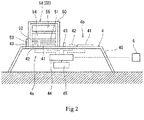
FIG. 2 is an enlarged view of major components ofFIG. 1 . -
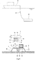
FIG. 3 is a diagram showing that a second battery unit is attached to a working apparatus before a first battery unit is detached from the working apparatus. -
FIG. 4 is a diagram showing that the first battery unit is detached from the working apparatus after the second battery unit is attached to the working apparatus. -
FIG. 1 shows an underwaterpower supply system 1 according to one embodiment of the present invention. The underwaterpower supply system 1 includes a workingapparatus 4 arranged underwater and anunderwater sailing body 3. - In the present embodiment, the working
apparatus 4 is an underwater station placed on the seabed and connected to anobservation device 6. The underwater station performs work, such as processing of observation data of theobservation device 6 and power supply to theobservation device 6. Examples of theobservation device 6 include a seismometer, a thermometer, a densitometer, a sonic meter, and a camera. It should be noted that the workingapparatus 4 may be an AUV which performs work, such as inspection of underwater structures and topographical survey of the seabed. - A
first battery unit 5A is detachably attached to the workingapparatus 4. Theunderwater sailing body 3 carries asecond battery unit 5B to the workingapparatus 4, detaches thefirst battery unit 5A from the workingapparatus 4, and attaches thesecond battery unit 5B to the workingapparatus 4. - The
underwater sailing body 3 is provided with a holding device (not shown). The holding device holds or releases thesecond battery unit 5B or thefirst battery unit 5A. - In the present embodiment, the
underwater sailing body 3 is an AUV which shuttles between the workingapparatus 4 and anunderwater station 23 suspended from asurface ship 21 through acable 22. Theunderwater station 23 charges a battery incorporated in the AUV and receives various data from a controller incorporated in the AUV. It should be noted that theunderwater station 23 may be omitted, and the AUV may shuttle between thesurface ship 21 and the workingapparatus 4. Or, theunderwater sailing body 3 may be a ROV (Remotely Operated Vehicle) connected to thesurface ship 21 through a cable or may be a manned submersible vessel. - The working
apparatus 4 includes two attachingportions apparatus 4 includes abase 40, and part of thebase 40 constitutes the attachingportions - As shown in
FIG. 2 , each of the attachingportions power receiving pad 41, afirst communication device 42, and a positioning fitting 43. Thefirst battery unit 5A is attached to one of the attachingportions first battery unit 5A is attached to the attachingportion 4a but may be attached to the attachingportion 4b). - Moreover, the working
apparatus 4 includes afirst controller 44 and anauxiliary battery 45 electrically connected to thefirst controller 44. Thefirst controller 44 is electrically connected to the power receivingpads 41 andfirst communication devices 42 of the attachingportions observation device 6 is electrically connected to thefirst controller 44. - For example, the
first controller 44 is a computer including memories (such as a ROM and a RAM), storages (such as a HDD and a SSD), and a CPU, and programs stored in the ROM are executed by the CPU. The processing of the observation data and the power supply to theobservation device 6 are performed by thefirst controller 44. - When the
first battery unit 5A is being detached from the workingapparatus 4, and thesecond battery unit 5B is not yet attached to the workingapparatus 4, theauxiliary battery 45 plays a role of supplying power to thefirst controller 44. After thefirst battery unit 5A or thesecond battery unit 5B is attached to the workingapparatus 4, theauxiliary battery 45 is charged by a below-describedbattery 54. - The
first battery unit 5A and thesecond battery unit 5B are the same in structure as each other. Specifically, each of thefirst battery unit 5A and thesecond battery unit 5B includes aframe 50, apower supplying pad 51, asecond communication device 52, thebattery 54, and asecond controller 55. Thepower supplying pad 51, thesecond communication device 52, thebattery 54, and thesecond controller 55 are arranged in theframe 50. It should be noted that the size of thebattery 54 of thefirst battery unit 5A and the size of thebattery 54 of thesecond battery unit 5B may be the same as each other or may be different from each other. - When the battery unit (5A or 5B) is attached to the attaching portion (4a or 4b) of the working
apparatus 4, theframe 50 is placed on thebase 40 of the workingapparatus 4. Theframe 50 includes a positioning fitting 53 that engages with the positioning fitting 43 of the workingapparatus 4. For example, one of thepositioning fittings positioning fittings - When the battery unit (5A or 5B) is attached to the attaching portion (4a or 4b) of the working
apparatus 4, thepower supplying pad 51 is opposed to thepower receiving pad 41 with a small gap, and thesecond communication device 52 is opposed to thefirst communication device 42 with a small gap. - The
power supplying pad 51 is capable of supplying electric power to thepower receiving pad 41 in a non-contact state. Thebattery 54 is electrically connected to thepower supplying pad 51. Thebattery 54 is also electrically connected to thesecond controller 55, and thesecond controller 55 is electrically connected to thesecond communication device 52. - For example, the
second controller 55 is a computer including memories (such as a ROM and a RAM), storages (such as a HDD and a SSD), and a CPU, and programs stored in the ROM are executed by the CPU. Thesecond controller 55 controls the amount of electric power supplied from thebattery 54 through thepower supplying pad 51 and thepower receiving pad 41 to thefirst controller 44. - Next, the operations of the
underwater sailing body 3 will be described. Although not shown in the drawings, the workingapparatus 4, theunderwater station 23, and theunderwater sailing body 3 include respective transponders for mutual acoustic communication. - As shown in
FIG. 1 , when thefirst battery unit 5A is being attached to the attachingportion 4a of the workingapparatus 4, and the amount of electric power stored in thebattery 54 of thefirst battery unit 5A is small, the workingapparatus 4 transmits such information to theunderwater station 23 or theunderwater sailing body 3 by the acoustic communication. Based on this, theunderwater sailing body 3 departs from theunderwater station 23. - After that, as shown in
FIG. 3 , theunderwater sailing body 3 carries thesecond battery unit 5B to the workingapparatus 4 and attaches thesecond battery unit 5B to the attachingportion 4b to which thefirst battery unit 5A is not being attached. Next, as shown inFIG. 4 , theunderwater sailing body 3 detaches thefirst battery unit 5A from the workingapparatus 4. - After that, the
underwater sailing body 3 returns to theunderwater station 23, and thebattery 54 of thefirst battery unit 5A is charged underwater by theunderwater station 23. It should be noted that in a case where theunderwater sailing body 3 shuttles between thesurface ship 21 and the workingapparatus 4, and when theunderwater sailing body 3 returns to thesurface ship 21, thefirst battery unit 5A may be pulled up onto thesurface ship 21 together with theunderwater sailing body 3, and thebattery 54 of thefirst battery unit 5A may be charged on the water. Or, when theunderwater sailing body 3 returns to thesurface ship 21, theunderwater sailing body 3 may stand by on the water, and only thefirst battery unit 5A may be pulled up onto thesurface ship 21. - When the
first battery unit 5A or thesecond battery unit 5B is being attached to the workingapparatus 4, the observation data of theobservation device 6 is transmitted from thefirst controller 44 through thefirst communication device 42 and thesecond communication device 52 to thesecond controller 55 and stored in thesecond controller 55. - As described above, in the underwater
power supply system 1 of the present embodiment, when the amount of electric power stored in thebattery 54 of thefirst battery unit 5A attached to the workingapparatus 4 becomes small, thesecond battery unit 5B is attached to the workingapparatus 4 in place of thefirst battery unit 5A. To be specific, thesurface ship 21 does not have to stand by on the sea until the completion of the charging of thebattery 54 of thefirst battery unit 5A. Therefore, a standby time of thesurface ship 21 can be shortened. - Moreover, in the present embodiment, the observation data is stored in the
second controller 55 of thefirst battery unit 5A and thesecond controller 55 of thesecond battery unit 5B. Therefore, the observation data can be collected at the same time when thebattery 54 of thefirst battery unit 5A or thebattery 54 of thesecond battery unit 5B is charged underwater at a position away from the working apparatus 4 (or at the same time when thebattery 54 is charged on the water in a case where thefirst battery unit 5A is pulled up onto thesurface ship 21 together with theunderwater sailing body 3 or only thefirst battery unit 5A is pulled up onto thesurface ship 21 as described above). - The present invention is not limited to the above embodiment, and various modifications may be made within the scope of the present invention.
- For example, the working
apparatus 4 does not necessarily have to include a plurality of attaching portions and may include only one attaching portion. In this case, it is desirable that the workingapparatus 4 include a temporarily placing space where thesecond battery unit 5B is temporarily placed before thefirst battery unit 5A is replaced with thesecond battery unit 5B. - It should be noted that when the working
apparatus 4 includes a plurality of attaching portions as in the above embodiment, thefirst battery unit 5A can be detached from the workingapparatus 4 after thesecond battery unit 5B is attached to the workingapparatus 4. With this, the workingapparatus 4 can continuously perform work while using thebattery 54 as the driving source. When the number of attaching portions is one, but the workingapparatus 4 includes theauxiliary battery 45, the workingapparatus 4 can continuously perform work when replacing thefirst battery unit 5A with thesecond battery unit 5B. - Moreover, in a case where the
underwater sailing body 3 shuttles between thesurface ship 21 and the workingapparatus 4, theunderwater sailing body 3 may collect, in a first shuttling operation, thefirst battery unit 5A in which the amount of electric power stored in thebattery 54 is small, and theunderwater sailing body 3 may carry thesecond battery unit 5B to the workingapparatus 4 in a second shuttling operation. Or, in a case where theunderwater station 23 is also provided with a plurality of attaching portions including respective power supplying pads for the battery units, theunderwater sailing body 3 may collect, in the first shuttling operation between theunderwater station 23 and the workingapparatus 4, thefirst battery unit 5A in which the amount of electric power stored in thebattery 54 is small, and theunderwater sailing body 3 may carry thesecond battery unit 5B to the workingapparatus 4 in the second shuttling operation. - Furthermore, two
underwater sailing bodies 3 that are anunderwater sailing body 3 for collecting thefirst battery unit 5A and anunderwater sailing bodies 3 for carrying thesecond battery unit 5B may be used. -
- 1
- underwater power supply system
- 21
- surface ship
- 23
- underwater station
- 3
- underwater sailing body
- 4
- working apparatus
- 4a, 4b
- attaching portion
- 41
- power receiving pad
- 42
- first communication device
- 44
- first controller
- 45
- auxiliary battery
- 5A
- first battery unit
- 5B
- second battery unit
- 51
- power supplying pad
- 52
- second communication device
- 54
- battery
- 55
- second controller
Claims (4)
- An underwater power supply system comprising:a working apparatus arranged underwater and including at least one power receiving pad;a first battery unit detachably attached to the working apparatus and including a power supplying pad and a battery, the power supplying pad being configured to supply electric power to the power receiving pad in a non-contact state, the battery being electrically connected to the power supplying pad; andan underwater sailing body configured to shuttle between the working apparatus and a surface ship or between the working apparatus and an underwater station suspended from the surface ship, the underwater sailing body being configured to carry a second battery unit to the working apparatus, detach the first battery unit from the working apparatus, and attach the second battery unit to the working apparatus, the second battery unit including a power supplying pad and a battery, the power supplying pad being configured to supply the electric power to the power receiving pad in a non-contact state, the battery being electrically connected to the power supplying pad.
- The underwater power supply system according to claim 1, wherein:the working apparatus includes a plurality of attaching portions each including the power receiving pad, and the first battery unit is attached to one of the plurality of attaching portions; andthe underwater sailing body attaches the second battery unit to the attaching portion which is one of the plurality of attaching portions and to which the first battery unit is not being attached.
- The underwater power supply system according to claim 1 or 2, wherein the working apparatus includes:a controller electrically connected to the power receiving pad; andan auxiliary battery configured to supply the electric power to the controller when the first battery unit is being detached from the working apparatus, and the second battery unit is not yet attached to the working apparatus.
- The underwater power supply system according to any one of claims 1 to 3, wherein:the working apparatus includesa first controller electrically connected to the power receiving pad and an observation device anda first communication device electrically connected to the first controller;each of the first battery unit and the second battery unit includesa second controller electrically connected to the battery anda second communication device electrically connected to the second controller; andwhen the first battery unit or the second battery unit is being attached to the working apparatus, observation data of the observation device is transmitted from the first controller through the first communication device and the second communication device to the second controller and stored in the second controller.
Applications Claiming Priority (2)
| Application Number | Priority Date | Filing Date | Title |
|---|---|---|---|
| JP2018114293A JP7068060B2 (en) | 2018-06-15 | 2018-06-15 | Underwater power supply system |
| PCT/JP2019/023635 WO2019240256A1 (en) | 2018-06-15 | 2019-06-14 | Underwater power supply system |
Publications (3)
| Publication Number | Publication Date |
|---|---|
| EP3808647A1 true EP3808647A1 (en) | 2021-04-21 |
| EP3808647A4 EP3808647A4 (en) | 2022-03-16 |
| EP3808647B1 EP3808647B1 (en) | 2023-08-02 |
Family
ID=68841951
Family Applications (1)
| Application Number | Title | Priority Date | Filing Date |
|---|---|---|---|
| EP19819339.3A Active EP3808647B1 (en) | 2018-06-15 | 2019-06-14 | Underwater power supply system |
Country Status (6)
| Country | Link |
|---|---|
| US (1) | US11239669B2 (en) |
| EP (1) | EP3808647B1 (en) |
| JP (1) | JP7068060B2 (en) |
| AU (1) | AU2019285867B2 (en) |
| FI (1) | FI3808647T3 (en) |
| WO (1) | WO2019240256A1 (en) |
Families Citing this family (3)
| Publication number | Priority date | Publication date | Assignee | Title |
|---|---|---|---|---|
| CN113895599B (en) * | 2021-12-09 | 2022-03-25 | 浙江大学 | Long-term duty AUV submarine connection base station and its non-contact operation and maintenance system and method |
| CN117104036A (en) * | 2023-08-30 | 2023-11-24 | 哈尔滨工程大学 | An AUV underwater charging platform |
| JP2025145800A (en) * | 2024-03-22 | 2025-10-03 | トヨタ自動車株式会社 | Underwater Energy Transfer System |
Family Cites Families (11)
| Publication number | Priority date | Publication date | Assignee | Title |
|---|---|---|---|---|
| US6223675B1 (en) * | 1999-09-20 | 2001-05-01 | Coflexip, S.A. | Underwater power and data relay |
| US6807921B2 (en) * | 2002-03-07 | 2004-10-26 | Dwight David Huntsman | Underwater vehicles |
| JP2004166459A (en) * | 2002-11-15 | 2004-06-10 | Mitsui Eng & Shipbuild Co Ltd | Wireless power supply |
| US6854410B1 (en) * | 2003-11-24 | 2005-02-15 | The United States Of America As Represented By The Secretary Of The Navy | Underwater investigation system using multiple unmanned vehicles |
| GB0719946D0 (en) * | 2007-10-12 | 2007-11-21 | Subsea 7 Ltd | Apparatus and method |
| KR20100129511A (en) * | 2009-06-01 | 2010-12-09 | 대우조선해양 주식회사 | Submersible Unmanned Mooring System and Its Operation Method |
| JP2013039876A (en) * | 2011-08-16 | 2013-02-28 | Nobufumi Edamura | Closed-circuit self-contained underwater breathing apparatus |
| DE102011121856A1 (en) * | 2011-12-21 | 2013-06-27 | Atlas Elektronik Gmbh | Combustion agent for clearing munitions, such as sea mines, underwater, ordnance clearance combination with unmanned underwater vehicle and such ordnance and apparatus for this purpose. |
| EP2834865B1 (en) * | 2012-08-07 | 2021-03-31 | EaglePicher Technologies, LLC | Underwater charging station |
| JP5812024B2 (en) * | 2013-02-15 | 2015-11-11 | 三菱電機株式会社 | Underwater elevator |
| ITUA20161587A1 (en) * | 2016-03-11 | 2017-09-11 | Saipem Spa | UNDERWATER VEHICLE WITHOUT CREW, SYSTEM AND METHOD FOR MAINTENANCE AND UNDERWATER INSPECTION |
-
2018
- 2018-06-15 JP JP2018114293A patent/JP7068060B2/en active Active
-
2019
- 2019-06-14 EP EP19819339.3A patent/EP3808647B1/en active Active
- 2019-06-14 AU AU2019285867A patent/AU2019285867B2/en active Active
- 2019-06-14 WO PCT/JP2019/023635 patent/WO2019240256A1/en not_active Ceased
- 2019-06-14 FI FIEP19819339.3T patent/FI3808647T3/en active
- 2019-06-14 US US17/252,426 patent/US11239669B2/en active Active
Also Published As
| Publication number | Publication date |
|---|---|
| EP3808647A4 (en) | 2022-03-16 |
| JP7068060B2 (en) | 2022-05-16 |
| AU2019285867A1 (en) | 2021-01-07 |
| EP3808647B1 (en) | 2023-08-02 |
| US11239669B2 (en) | 2022-02-01 |
| US20210188104A1 (en) | 2021-06-24 |
| JP2019217796A (en) | 2019-12-26 |
| WO2019240256A1 (en) | 2019-12-19 |
| AU2019285867B2 (en) | 2021-11-11 |
| FI3808647T3 (en) | 2023-11-01 |
Similar Documents
| Publication | Publication Date | Title |
|---|---|---|
| EP3808647B1 (en) | Underwater power supply system | |
| CN114872841A (en) | Autonomous underwater detection system and method for automatically recovering and laying AUV | |
| US6807921B2 (en) | Underwater vehicles | |
| RU2013153205A (en) | AUTONOMOUS UNDERWATER SYSTEM FOR FOUR-DIMENSIONAL MONITORING OF THE ENVIRONMENT | |
| CN108988449A (en) | A submarine power station system applied to underwater vehicles | |
| CN104396047A (en) | underwater charging station | |
| CN107187565B (en) | A system and method for underwater online charging | |
| US7194975B2 (en) | Unmanned underwater vehicle health monitoring system and method | |
| KR20150105089A (en) | Underwater robot operating apparatus and underwater robot operating method therewith | |
| CN206871329U (en) | A kind of underwater system to charge online | |
| CN107014971A (en) | Underwater hiding-machine with efficient charging and remote data transmission function uses buoy base station | |
| CN105700412A (en) | Supervision on-duty control system and supervision on-duty control method for time-sharing operation of underwater robot/submersible | |
| Kawasaki et al. | Development of AUV" Marine Bird" with underwater docking and recharging system | |
| Murashima et al. | 7000 m class ROV KAIKO7000 | |
| CN109357688A (en) | An underwater integrated navigation system test cabin device | |
| CN105548517A (en) | Continuous monitoring method for water quality survey in offshore environment | |
| CN221841497U (en) | An unmanned remote-controlled underwater robot communication system | |
| CN208921140U (en) | An underwater integrated navigation system test cabin device | |
| CN106218816A (en) | A kind of Multifunctional marine acoustic buoy | |
| KR101224893B1 (en) | Emergency module device for autonomous underwater vehicle | |
| CN104392584A (en) | Emergency call watch equipment for offshore worker | |
| KR20100129511A (en) | Submersible Unmanned Mooring System and Its Operation Method | |
| CN110260926A (en) | Intelligent monitoring and protection system for energy supply of deep-sea manned submersible | |
| CN204726643U (en) | A kind of modularization under-water robot | |
| Manos et al. | Underwater Robotics: Challenges and Solutions |
Legal Events
| Date | Code | Title | Description |
|---|---|---|---|
| STAA | Information on the status of an ep patent application or granted ep patent |
Free format text: STATUS: THE INTERNATIONAL PUBLICATION HAS BEEN MADE |
|
| PUAI | Public reference made under article 153(3) epc to a published international application that has entered the european phase |
Free format text: ORIGINAL CODE: 0009012 |
|
| STAA | Information on the status of an ep patent application or granted ep patent |
Free format text: STATUS: REQUEST FOR EXAMINATION WAS MADE |
|
| 17P | Request for examination filed |
Effective date: 20201201 |
|
| AK | Designated contracting states |
Kind code of ref document: A1 Designated state(s): AL AT BE BG CH CY CZ DE DK EE ES FI FR GB GR HR HU IE IS IT LI LT LU LV MC MK MT NL NO PL PT RO RS SE SI SK SM TR |
|
| AX | Request for extension of the european patent |
Extension state: BA ME |
|
| DAV | Request for validation of the european patent (deleted) | ||
| DAX | Request for extension of the european patent (deleted) | ||
| A4 | Supplementary search report drawn up and despatched |
Effective date: 20220216 |
|
| RIC1 | Information provided on ipc code assigned before grant |
Ipc: B63G 8/00 20060101ALI20220210BHEP Ipc: B63C 11/52 20060101ALI20220210BHEP Ipc: B60L 53/80 20190101AFI20220210BHEP |
|
| REG | Reference to a national code |
Ref country code: DE Ref legal event code: R079 Ref country code: DE Ref legal event code: R079 Ref document number: 602019034202 Country of ref document: DE Free format text: PREVIOUS MAIN CLASS: B63C0011000000 Ipc: B60L0053800000 |
|
| GRAP | Despatch of communication of intention to grant a patent |
Free format text: ORIGINAL CODE: EPIDOSNIGR1 |
|
| STAA | Information on the status of an ep patent application or granted ep patent |
Free format text: STATUS: GRANT OF PATENT IS INTENDED |
|
| RIC1 | Information provided on ipc code assigned before grant |
Ipc: B63G 8/00 20060101ALI20230220BHEP Ipc: B63C 11/52 20060101ALI20230220BHEP Ipc: B60L 53/80 20190101AFI20230220BHEP |
|
| INTG | Intention to grant announced |
Effective date: 20230316 |
|
| GRAS | Grant fee paid |
Free format text: ORIGINAL CODE: EPIDOSNIGR3 |
|
| GRAA | (expected) grant |
Free format text: ORIGINAL CODE: 0009210 |
|
| STAA | Information on the status of an ep patent application or granted ep patent |
Free format text: STATUS: THE PATENT HAS BEEN GRANTED |
|
| AK | Designated contracting states |
Kind code of ref document: B1 Designated state(s): AL AT BE BG CH CY CZ DE DK EE ES FI FR GB GR HR HU IE IS IT LI LT LU LV MC MK MT NL NO PL PT RO RS SE SI SK SM TR |
|
| REG | Reference to a national code |
Ref country code: GB Ref legal event code: FG4D |
|
| REG | Reference to a national code |
Ref country code: CH Ref legal event code: EP |
|
| REG | Reference to a national code |
Ref country code: DE Ref legal event code: R096 Ref document number: 602019034202 Country of ref document: DE |
|
| REG | Reference to a national code |
Ref country code: IE Ref legal event code: FG4D |
|
| REG | Reference to a national code |
Ref country code: FI Ref legal event code: FGE |
|
| REG | Reference to a national code |
Ref country code: NO Ref legal event code: T2 Effective date: 20230802 |
|
| REG | Reference to a national code |
Ref country code: LT Ref legal event code: MG9D |
|
| REG | Reference to a national code |
Ref country code: NL Ref legal event code: MP Effective date: 20230802 |
|
| REG | Reference to a national code |
Ref country code: AT Ref legal event code: MK05 Ref document number: 1594324 Country of ref document: AT Kind code of ref document: T Effective date: 20230802 |
|
| PG25 | Lapsed in a contracting state [announced via postgrant information from national office to epo] |
Ref country code: GR Free format text: LAPSE BECAUSE OF FAILURE TO SUBMIT A TRANSLATION OF THE DESCRIPTION OR TO PAY THE FEE WITHIN THE PRESCRIBED TIME-LIMIT Effective date: 20231103 |
|
| PG25 | Lapsed in a contracting state [announced via postgrant information from national office to epo] |
Ref country code: IS Free format text: LAPSE BECAUSE OF FAILURE TO SUBMIT A TRANSLATION OF THE DESCRIPTION OR TO PAY THE FEE WITHIN THE PRESCRIBED TIME-LIMIT Effective date: 20231202 |
|
| PG25 | Lapsed in a contracting state [announced via postgrant information from national office to epo] |
Ref country code: SE Free format text: LAPSE BECAUSE OF FAILURE TO SUBMIT A TRANSLATION OF THE DESCRIPTION OR TO PAY THE FEE WITHIN THE PRESCRIBED TIME-LIMIT Effective date: 20230802 Ref country code: RS Free format text: LAPSE BECAUSE OF FAILURE TO SUBMIT A TRANSLATION OF THE DESCRIPTION OR TO PAY THE FEE WITHIN THE PRESCRIBED TIME-LIMIT Effective date: 20230802 Ref country code: PT Free format text: LAPSE BECAUSE OF FAILURE TO SUBMIT A TRANSLATION OF THE DESCRIPTION OR TO PAY THE FEE WITHIN THE PRESCRIBED TIME-LIMIT Effective date: 20231204 Ref country code: NL Free format text: LAPSE BECAUSE OF FAILURE TO SUBMIT A TRANSLATION OF THE DESCRIPTION OR TO PAY THE FEE WITHIN THE PRESCRIBED TIME-LIMIT Effective date: 20230802 Ref country code: LV Free format text: LAPSE BECAUSE OF FAILURE TO SUBMIT A TRANSLATION OF THE DESCRIPTION OR TO PAY THE FEE WITHIN THE PRESCRIBED TIME-LIMIT Effective date: 20230802 Ref country code: LT Free format text: LAPSE BECAUSE OF FAILURE TO SUBMIT A TRANSLATION OF THE DESCRIPTION OR TO PAY THE FEE WITHIN THE PRESCRIBED TIME-LIMIT Effective date: 20230802 Ref country code: IS Free format text: LAPSE BECAUSE OF FAILURE TO SUBMIT A TRANSLATION OF THE DESCRIPTION OR TO PAY THE FEE WITHIN THE PRESCRIBED TIME-LIMIT Effective date: 20231202 Ref country code: HR Free format text: LAPSE BECAUSE OF FAILURE TO SUBMIT A TRANSLATION OF THE DESCRIPTION OR TO PAY THE FEE WITHIN THE PRESCRIBED TIME-LIMIT Effective date: 20230802 Ref country code: GR Free format text: LAPSE BECAUSE OF FAILURE TO SUBMIT A TRANSLATION OF THE DESCRIPTION OR TO PAY THE FEE WITHIN THE PRESCRIBED TIME-LIMIT Effective date: 20231103 Ref country code: AT Free format text: LAPSE BECAUSE OF FAILURE TO SUBMIT A TRANSLATION OF THE DESCRIPTION OR TO PAY THE FEE WITHIN THE PRESCRIBED TIME-LIMIT Effective date: 20230802 |
|
| PG25 | Lapsed in a contracting state [announced via postgrant information from national office to epo] |
Ref country code: PL Free format text: LAPSE BECAUSE OF FAILURE TO SUBMIT A TRANSLATION OF THE DESCRIPTION OR TO PAY THE FEE WITHIN THE PRESCRIBED TIME-LIMIT Effective date: 20230802 |
|
| PG25 | Lapsed in a contracting state [announced via postgrant information from national office to epo] |
Ref country code: ES Free format text: LAPSE BECAUSE OF FAILURE TO SUBMIT A TRANSLATION OF THE DESCRIPTION OR TO PAY THE FEE WITHIN THE PRESCRIBED TIME-LIMIT Effective date: 20230802 |
|
| PG25 | Lapsed in a contracting state [announced via postgrant information from national office to epo] |
Ref country code: SM Free format text: LAPSE BECAUSE OF FAILURE TO SUBMIT A TRANSLATION OF THE DESCRIPTION OR TO PAY THE FEE WITHIN THE PRESCRIBED TIME-LIMIT Effective date: 20230802 Ref country code: RO Free format text: LAPSE BECAUSE OF FAILURE TO SUBMIT A TRANSLATION OF THE DESCRIPTION OR TO PAY THE FEE WITHIN THE PRESCRIBED TIME-LIMIT Effective date: 20230802 Ref country code: ES Free format text: LAPSE BECAUSE OF FAILURE TO SUBMIT A TRANSLATION OF THE DESCRIPTION OR TO PAY THE FEE WITHIN THE PRESCRIBED TIME-LIMIT Effective date: 20230802 Ref country code: EE Free format text: LAPSE BECAUSE OF FAILURE TO SUBMIT A TRANSLATION OF THE DESCRIPTION OR TO PAY THE FEE WITHIN THE PRESCRIBED TIME-LIMIT Effective date: 20230802 Ref country code: DK Free format text: LAPSE BECAUSE OF FAILURE TO SUBMIT A TRANSLATION OF THE DESCRIPTION OR TO PAY THE FEE WITHIN THE PRESCRIBED TIME-LIMIT Effective date: 20230802 Ref country code: CZ Free format text: LAPSE BECAUSE OF FAILURE TO SUBMIT A TRANSLATION OF THE DESCRIPTION OR TO PAY THE FEE WITHIN THE PRESCRIBED TIME-LIMIT Effective date: 20230802 Ref country code: SK Free format text: LAPSE BECAUSE OF FAILURE TO SUBMIT A TRANSLATION OF THE DESCRIPTION OR TO PAY THE FEE WITHIN THE PRESCRIBED TIME-LIMIT Effective date: 20230802 |
|
| REG | Reference to a national code |
Ref country code: DE Ref legal event code: R097 Ref document number: 602019034202 Country of ref document: DE |
|
| PLBE | No opposition filed within time limit |
Free format text: ORIGINAL CODE: 0009261 |
|
| STAA | Information on the status of an ep patent application or granted ep patent |
Free format text: STATUS: NO OPPOSITION FILED WITHIN TIME LIMIT |
|
| 26N | No opposition filed |
Effective date: 20240503 |
|
| PG25 | Lapsed in a contracting state [announced via postgrant information from national office to epo] |
Ref country code: SI Free format text: LAPSE BECAUSE OF FAILURE TO SUBMIT A TRANSLATION OF THE DESCRIPTION OR TO PAY THE FEE WITHIN THE PRESCRIBED TIME-LIMIT Effective date: 20230802 |
|
| PG25 | Lapsed in a contracting state [announced via postgrant information from national office to epo] |
Ref country code: BG Free format text: LAPSE BECAUSE OF FAILURE TO SUBMIT A TRANSLATION OF THE DESCRIPTION OR TO PAY THE FEE WITHIN THE PRESCRIBED TIME-LIMIT Effective date: 20230802 |
|
| PG25 | Lapsed in a contracting state [announced via postgrant information from national office to epo] |
Ref country code: BG Free format text: LAPSE BECAUSE OF FAILURE TO SUBMIT A TRANSLATION OF THE DESCRIPTION OR TO PAY THE FEE WITHIN THE PRESCRIBED TIME-LIMIT Effective date: 20230802 |
|
| REG | Reference to a national code |
Ref country code: DE Ref legal event code: R119 Ref document number: 602019034202 Country of ref document: DE |
|
| PG25 | Lapsed in a contracting state [announced via postgrant information from national office to epo] |
Ref country code: MC Free format text: LAPSE BECAUSE OF FAILURE TO SUBMIT A TRANSLATION OF THE DESCRIPTION OR TO PAY THE FEE WITHIN THE PRESCRIBED TIME-LIMIT Effective date: 20230802 |
|
| REG | Reference to a national code |
Ref country code: CH Ref legal event code: PL |
|
| PG25 | Lapsed in a contracting state [announced via postgrant information from national office to epo] |
Ref country code: LU Free format text: LAPSE BECAUSE OF NON-PAYMENT OF DUE FEES Effective date: 20240614 |
|
| PG25 | Lapsed in a contracting state [announced via postgrant information from national office to epo] |
Ref country code: DE Free format text: LAPSE BECAUSE OF NON-PAYMENT OF DUE FEES Effective date: 20250101 |
|
| PG25 | Lapsed in a contracting state [announced via postgrant information from national office to epo] |
Ref country code: IE Free format text: LAPSE BECAUSE OF NON-PAYMENT OF DUE FEES Effective date: 20240614 |
|
| PG25 | Lapsed in a contracting state [announced via postgrant information from national office to epo] |
Ref country code: BE Free format text: LAPSE BECAUSE OF NON-PAYMENT OF DUE FEES Effective date: 20240630 Ref country code: CH Free format text: LAPSE BECAUSE OF NON-PAYMENT OF DUE FEES Effective date: 20240630 |
|
| PG25 | Lapsed in a contracting state [announced via postgrant information from national office to epo] |
Ref country code: FR Free format text: LAPSE BECAUSE OF NON-PAYMENT OF DUE FEES Effective date: 20240630 |
|
| REG | Reference to a national code |
Ref country code: BE Ref legal event code: MM Effective date: 20240630 |
|
| PG25 | Lapsed in a contracting state [announced via postgrant information from national office to epo] |
Ref country code: CY Free format text: LAPSE BECAUSE OF FAILURE TO SUBMIT A TRANSLATION OF THE DESCRIPTION OR TO PAY THE FEE WITHIN THE PRESCRIBED TIME-LIMIT; INVALID AB INITIO Effective date: 20190614 |
|
| PG25 | Lapsed in a contracting state [announced via postgrant information from national office to epo] |
Ref country code: HU Free format text: LAPSE BECAUSE OF FAILURE TO SUBMIT A TRANSLATION OF THE DESCRIPTION OR TO PAY THE FEE WITHIN THE PRESCRIBED TIME-LIMIT; INVALID AB INITIO Effective date: 20190614 |
|
| PG25 | Lapsed in a contracting state [announced via postgrant information from national office to epo] |
Ref country code: TR Free format text: LAPSE BECAUSE OF FAILURE TO SUBMIT A TRANSLATION OF THE DESCRIPTION OR TO PAY THE FEE WITHIN THE PRESCRIBED TIME-LIMIT Effective date: 20230802 |
|
| PGFP | Annual fee paid to national office [announced via postgrant information from national office to epo] |
Ref country code: GB Payment date: 20260507 Year of fee payment: 8 |
|
| PGFP | Annual fee paid to national office [announced via postgrant information from national office to epo] |
Ref country code: IT Payment date: 20260522 Year of fee payment: 8 |
|
| PGFP | Annual fee paid to national office [announced via postgrant information from national office to epo] |
Ref country code: NO Payment date: 20260610 Year of fee payment: 8 |
|
| PGFP | Annual fee paid to national office [announced via postgrant information from national office to epo] |
Ref country code: FI Payment date: 20260623 Year of fee payment: 8 |