EP3808288A1 - Lithotripsievorrichtung - Google Patents
Lithotripsievorrichtung Download PDFInfo
- Publication number
- EP3808288A1 EP3808288A1 EP20201314.0A EP20201314A EP3808288A1 EP 3808288 A1 EP3808288 A1 EP 3808288A1 EP 20201314 A EP20201314 A EP 20201314A EP 3808288 A1 EP3808288 A1 EP 3808288A1
- Authority
- EP
- European Patent Office
- Prior art keywords
- probe
- lithotripsy device
- amorphous material
- probe head
- rod
- Prior art date
- Legal status (The legal status is an assumption and is not a legal conclusion. Google has not performed a legal analysis and makes no representation as to the accuracy of the status listed.)
- Granted
Links
Images



Classifications
-
- A—HUMAN NECESSITIES
- A61—MEDICAL OR VETERINARY SCIENCE; HYGIENE
- A61B—DIAGNOSIS; SURGERY; IDENTIFICATION
- A61B17/00—Surgical instruments, devices or methods
- A61B17/22—Implements for squeezing-off ulcers or the like on inner organs of the body; Implements for scraping-out cavities of body organs, e.g. bones; for invasive removal or destruction of calculus using mechanical vibrations; for removing obstructions in blood vessels, not otherwise provided for
- A61B17/22004—Implements for squeezing-off ulcers or the like on inner organs of the body; Implements for scraping-out cavities of body organs, e.g. bones; for invasive removal or destruction of calculus using mechanical vibrations; for removing obstructions in blood vessels, not otherwise provided for using mechanical vibrations, e.g. ultrasonic shock waves
- A61B17/22012—Implements for squeezing-off ulcers or the like on inner organs of the body; Implements for scraping-out cavities of body organs, e.g. bones; for invasive removal or destruction of calculus using mechanical vibrations; for removing obstructions in blood vessels, not otherwise provided for using mechanical vibrations, e.g. ultrasonic shock waves in direct contact with, or very close to, the obstruction or concrement
-
- A—HUMAN NECESSITIES
- A61—MEDICAL OR VETERINARY SCIENCE; HYGIENE
- A61B—DIAGNOSIS; SURGERY; IDENTIFICATION
- A61B17/00—Surgical instruments, devices or methods
- A61B2017/00831—Material properties
-
- A—HUMAN NECESSITIES
- A61—MEDICAL OR VETERINARY SCIENCE; HYGIENE
- A61B—DIAGNOSIS; SURGERY; IDENTIFICATION
- A61B17/00—Surgical instruments, devices or methods
- A61B17/22—Implements for squeezing-off ulcers or the like on inner organs of the body; Implements for scraping-out cavities of body organs, e.g. bones; for invasive removal or destruction of calculus using mechanical vibrations; for removing obstructions in blood vessels, not otherwise provided for
- A61B17/22004—Implements for squeezing-off ulcers or the like on inner organs of the body; Implements for scraping-out cavities of body organs, e.g. bones; for invasive removal or destruction of calculus using mechanical vibrations; for removing obstructions in blood vessels, not otherwise provided for using mechanical vibrations, e.g. ultrasonic shock waves
- A61B17/22012—Implements for squeezing-off ulcers or the like on inner organs of the body; Implements for scraping-out cavities of body organs, e.g. bones; for invasive removal or destruction of calculus using mechanical vibrations; for removing obstructions in blood vessels, not otherwise provided for using mechanical vibrations, e.g. ultrasonic shock waves in direct contact with, or very close to, the obstruction or concrement
- A61B2017/22014—Implements for squeezing-off ulcers or the like on inner organs of the body; Implements for scraping-out cavities of body organs, e.g. bones; for invasive removal or destruction of calculus using mechanical vibrations; for removing obstructions in blood vessels, not otherwise provided for using mechanical vibrations, e.g. ultrasonic shock waves in direct contact with, or very close to, the obstruction or concrement the ultrasound transducer being outside patient's body; with an ultrasound transmission member; with a wave guide; with a vibrated guide wire
- A61B2017/22015—Implements for squeezing-off ulcers or the like on inner organs of the body; Implements for scraping-out cavities of body organs, e.g. bones; for invasive removal or destruction of calculus using mechanical vibrations; for removing obstructions in blood vessels, not otherwise provided for using mechanical vibrations, e.g. ultrasonic shock waves in direct contact with, or very close to, the obstruction or concrement the ultrasound transducer being outside patient's body; with an ultrasound transmission member; with a wave guide; with a vibrated guide wire with details of the transmission member
Definitions
- the invention relates to a lithotripsy device, in particular an intracorporeal lithotripsy device, according to the preamble of claim 1.
- lithotripsy device which comprises a smashing unit, the smashing unit being set up to remove concretions and comprising at least one probe set up to act on concretions, and at least one pulse unit that transmits at least indirect pulses to the probe.
- the invention is based on a lithotripsy device, in particular an intracorporeal lithotripsy device, with a smashing unit which is set up to remove concretions and which comprises at least one probe set up for at least indirect application of concretions, as well as at least one pulse unit which at least indirectly transmits pulses to the probe, which has a probe rod for the at least indirect application of calculus and a probe head for the reception of impulses.
- the fragmentation unit consists at least partially, in particular at least to a large extent and particularly preferably completely, of an amorphous material , which has an elastic limit of at least 1.5% and / or a strength of at least 500 MPa.
- this can improve efficiency.
- the use of the amorphous material can advantageously be used to improve energy transfer between components of the lithotripsy device and / or to the calculus, as a result of which an improvement in energy efficiency in the operation of the lithotripsy device can be achieved.
- the use of the amorphous material can advantageously reduce signs of wear and / or increase the service life of components and parts of the lithotripsy device, whereby an improvement in component efficiency can be achieved. Overall, energy efficiency and component efficiency can thus be improved in particular at the same time.
- a “lithotripsy device” is to be understood as meaning, in particular, a preferably functional component, in particular a subassembly and / or a construction and / or a functional component of a lithotripter.
- the lithotripsy device can preferably form the lithotripter at least partially, preferably at least to a large extent and particularly preferably completely.
- the lithotripsy device is set up to destroy concretions.
- "Concrements” are to be understood in particular as solid structures formed in bodies by deposition, which at least partially, preferably at least a large part and particularly preferably completely consist of salts, such as kidney stones, gallstones, urinary stones, salivary stones or the like.
- the lithotripsy device is preferably designed as an intracorporeal lithotripsy device, which is designed to be introduced at least partially and preferably at least to a large extent into an in particular artificial and / or natural opening, in particular a body opening, in order to smash and / or close concretions that have accumulated there remove.
- “Set up” is to be understood in particular as specifically programmed, designed, designed and / or equipped. The fact that a component is set up for a specific function is to be understood in particular to mean that the component can perform this specific function in at least one application and / or Operational condition fulfilled and / or executes.
- a “shattering unit” is to be understood in particular as a unit which is composed at least of the, in particular, intracorporeal probe and the pulse unit.
- the disintegration unit can furthermore have further units, components and parts.
- a “probe” is to be understood in particular as a rod-shaped, tubular and / or hose-shaped component which is set up for examination and / or treatment.
- the probe is preferably designed as an intracorporeal probe.
- an "intracorporeal probe” is to be understood as meaning, in particular, a probe, and in particular a part of the lithotripsy device, which is designed to be inserted at least partially, preferably at least for the most part and particularly preferably completely, into an in particular artificial and / or natural opening, in particular body opening, to be introduced, for example, to smash and / or remove concretions that have accumulated there.
- the probe has at least one 7, which is set up to contact concretions directly and, in particular, to transmit impulses to them.
- the probe has in particular at least one probe head which is set up to receive the pulses provided by the pulse unit.
- the probe has, in particular, a probe rod which at least indirectly transmits recorded pulses from the probe head to the probe tip.
- At least indirectly should be understood to mean in particular indirect but preferably also directly, that is to say in particular directly.
- the probe head is preferably formed separately from the probe rod.
- the probe is at least partially, preferably at least to a large extent, and particularly preferably completely, designed in one piece.
- the fact that "a component and a further component are at least partially formed / connected in one piece” is to be understood in particular to mean that at least one element and / or part of the component and at least one element and / or part of the further component are constructed / connected in one piece .
- “In one piece” is intended to be connected in particular at least in a materially bonded manner, for example by a welding process, an adhesive process, an injection molding process and / or another one that appears sensible to a person skilled in the art Process, and / or advantageously be understood as being formed in one piece, such as, for example, by production from a cast and / or by production in a one-component or multi-component injection molding process and advantageously from a single blank.
- the probe tip and the probe rod could be formed in one piece.
- “Impulses” are to be understood as meaning, in particular, shock pulses and / or oscillation pulses.
- a “pulse unit” is to be understood in particular as a unit which generates and / or provides pulses to be transmitted.
- amorphous material is to be understood in particular as a material which has an irregular, preferably non-crystalline, arrangement of atoms and which advantageously only has short-range order but not long-range order.
- the amorphous material has, in particular, an elastic limit of at least 1.5%, preferably of at least 1.75% and particularly preferably of at least 2% and / or in particular of at most 2.75%, preferably of at most 2.5 and particularly preferably of at most 2.25% Elasticity limit of at least essentially 3%.
- the amorphous W Material has in particular a strength of at least 500 MPa, preferably of at least 1000 MPa and particularly preferably of at least 1500 MPa and / or in particular of at most 3400 MPa, preferably of at most 2900 MPa and particularly preferably of at most 2400 MPa.
- a strength of the amorphous material is very particularly preferably at least essentially 2000 MPa.
- a ratio of the elastic limit and the strength of the amorphous material is at least 400 MPa /%, preferably at least 600 MPa /% and particularly preferably at least 800 MPa /% and / or at most 1600 MPa /%, preferably at most 1400 MPa /% and particularly preferably at most 1200 MPa /%.
- a ratio of the strength and the elastic limit is very particularly preferably at least essentially 1000 MPa /%.
- the amorphous material is metallic glass.
- Efficiency can advantageously be further improved.
- metallic glasses have high elasticity limits corresponding to the requirement, which improves elastic energy transmission and thus energy efficiency.
- metallic glasses have a high level of strength in accordance with the requirement, which increases the service life and thus the component efficiency.
- Metallic glass is to be understood as meaning, in particular, a material which comprises at least one metal which is present in an amorphous structure.
- Metallic glass should also be understood to mean, in particular, amorphous metal.
- the metallic glass is preferably an alloy of metals or non-metals and metals.
- the amorphous material comprises at least one metal, at least one transition metal, at least one alkaline earth metal and / or a mixture of these.
- a strength and / or elastic limit can advantageously be increased further, as a result of which efficiency can be further improved.
- the metal can in particular be copper, aluminum and / or the like.
- the transition metals can be zirconium, niobium, titanium, nickel and / or the like.
- the alkaline earth metal can be beryllium, magnesium and / or the like.
- the amorphous material is an alloy of metals, transition metals and / or alkaline earth metals.
- the amorphous material is particularly preferably a metallic glass, in particular Vitreloy TM 1, Vitreloy TM 1b, Vitreloy TM 4, Vitreloy TM 101, Vitreloy TM 105, Vitreloy TM 106, Vitreloy TM 106a, and / or AMZ TM 4 .
- the amorphous material has, for example, one of the following compositions: Vitreloy TM 1: Zr 41.2 Be 22.5 Ti 13.8 Cu 12.5 Ni 10 (at%) Vitreloy TM 1b: Zr 44 Be 25 Ti 11 Cu 10 Ni 10 (at%) Vitreloy TM 4: Zr 46.75 Ti 8; 25 Cu 7.5 Ni 10 Be 27.5 (at%) Vitreloy TM 101: Cu 47 Ti 34 Zr 11 Ni 8 (at%) Vitreloy TM 105: Zr 52.5 Cu 17.9 Ni 14.6 Al 10 Ti 5 (at%) Vitreloy TM 106: Zr 57 Cu 15.4 Ni 12.6 Al 10 Nb 5 (at%) Vitreloy TM 106a: Zr 58.5 Cu 15.6 Ni 12.8 Al 10.3 Nb 2.8 (at%) AMZ TM 4: Zr 59.3 Cu 28.8 Al 10.4 Nb 1.5 (at%)
- the amorphous material could be based on copper and / or titanium.
- the fact that the amorphous material "is based on a chemical element" is to be understood in particular as meaning that this chemical element makes up the largest proportion of the amorphous material.
- amorphous materials based on zirconium in particular have the requirement of correspondingly high strengths and elasticity limits in order to advantageously further increase efficiency, it is proposed in a preferred embodiment of the invention that the aforementioned amorphous material be based on zirconium.
- zirconium forms the largest proportion of the amorphous materials Vitreloy TM 106 or AMZ TM 4.
- the amorphous material consists of at least 40%, preferably at least 45%, particularly preferably at least 50% and very particularly preferably at least 55% zirconium.
- the amorphous material is particularly preferably free from beryllium and / or niobium, as a result of which a biocompatibility of the amorphous material can advantageously be improved.
- the probe consists at least partially, in particular at least to a large extent and particularly preferably completely, of the amorphous material. Energy efficiency can advantageously be increased further. In particular, an energy transfer between the projectile and the probe can be improved.
- the probe is preferably made up of several parts. Particularly preferably, the probe consists at most partially, that is to say for example always less than completely, of the amorphous material, as a result of which costs can advantageously be saved.
- the probe head set up to receive pulses consists at least partially, in particular at least to a large extent and particularly preferably completely, of the amorphous material. Energy efficiency can advantageously be increased even further. In particular, an energy transfer between projectile and probe can be further improved.
- the probe head is preferably designed in one piece.
- the probe rod be free of the amorphous material.
- An efficiency can advantageously be increased.
- a component efficiency can be increased, since compared with the probe rod separately from one to the amorphous material cheaper material such as steel, titanium or the like can be produced.
- cheaper material such as steel, titanium or the like can be produced.
- the probe tip of the probe is free of the amorphous material.
- the probe rod and the probe head are positively and / or non-positively, in particular frictionally, connected to one another.
- an energy transfer between these components can advantageously be further improved.
- Unintentional triggering of the components can also advantageously be avoided, as a result of which, in particular, service life and thus component efficiency can be improved.
- a production and / or assembly efficiency can be improved or a production and / or assembly can be simplified in a particularly advantageous manner.
- a "positive and / or non-positive connection” is to be understood in particular to be connected, preferably releasably connected, with a holding force between two components preferably via a geometric engagement of the components in one another and / or via a frictional force, which is preferably between the components acts, is transmitted.
- the probe have an engagement area in which the probe rod and the probe head are in engagement with one another.
- energy efficiency and / or component efficiency can be further improved.
- manufacture and / or assembly can be simplified.
- An “engagement” is to be understood in particular to mean that a component encloses another component on at least three sides.
- a “page” is to be understood in particular as an imaginary plane which is oriented perpendicular to a coordinate axis, in particular an abscissa axis, an ordinate axis and / or an application axis. Accordingly, a component can be surrounded by a maximum of six sides in a three-dimensional coordinate system.
- the engagement area corresponds to an entire main extension of the probe head.
- an extension of the engagement area is advantageously smaller than a main extension of the probe head.
- a main extension of a component should in particular, a longest extent of the component along its main direction of extent is understood here.
- a “main direction of extent” of a component is to be understood in particular as a direction which runs parallel to a longest edge of a smallest imaginary cuboid which just completely encloses the component.
- the engagement area is in particular at least partially formed by an engagement section of the probe rod. Furthermore, the engagement area is at least partially formed by an engagement section of the probe rod.
- the 6 can preferably be a full recess.
- a connection between probe head and probe rod can advantageously be further improved by, as proposed in a preferred embodiment of the invention, the engagement area extending over at least 3 mm, preferably at least 3.5 mm and particularly preferably at least 4 mm along a main axis of extension of the probe rod and / or the probe head. Furthermore, the engagement area extends in particular over a maximum of 7 mm, preferably a maximum of 6 mm and particularly preferably a maximum of 5 mm, along a main axis of extension of the probe rod and / or the probe head.
- a “main axis of extension” is to be understood in particular as an axis which runs parallel to a main direction of extension of the component and in particular through its mass and / or geometric center.
- the extension of the engagement area is preferably significantly smaller than a main extension of the probe rod and / or the probe head. "Much smaller” is to be understood here in particular as less than half.
- the probe rod could surround the probe head in the area of engagement, for example if the probe rod were to be widened.
- the probe head surrounds the probe rod in the engagement area. Energy efficiency and / or component efficiency can advantageously be further improved. In particular, manufacture and / or assembly can be further simplified.
- the probe head surrounds the probe rod on at least four sides. The probe head particularly preferably surrounds the probe rod on five sides.
- the probe head and / or the probe rod be profiled in the engagement area. Energy efficiency and / or component efficiency can advantageously be particularly improved.
- either the probe head or the probe rod can be profiled.
- both the probe head and the probe rod are profiled.
- the fact that a component is profiled is to be understood in particular to mean that it is provided with a profiling in certain areas.
- the profiling preferably has an undulation, a thread, notches, projections and / or the like.
- Energy efficiency and / or component efficiency can be particularly improved if the probe head and the probe rod, as proposed, are pressed together, in particular crimped.
- manufacture and / or assembly can be simplified.
- the probe head and / or the probe rod are preferably pressed together by being deformed.
- the probe head is pressed, in particular crimped, radially with the probe rod.
- a profiled portion of the probe head and / or the probe rod preferably cut into one another in the engagement area.
- the probe head and the probe rod are materially connected to one another.
- Energy efficiency and / or component efficiency can advantageously be further improved.
- “Cohesively connected” is to be understood in particular to mean that the objects are held together by atomic or molecular forces, such as, for example, during soldering, welding, gluing and / or vulcanizing.
- the probe head and the probe rod are welded to one another.
- the probe head and the probe rod are adhesively connected to one another. A particularly efficient connection can advantageously be created.
- the probe head and the probe rod are encapsulated with one another.
- An efficient connection can advantageously be created.
- manufacture and / or assembly can be simplified.
- the probe rod is overmolded by the probe head.
- the probe rod and probe head together preferably form a multi-component injection-molded assembly.
- the impulse unit comprises at least one impact unit, which comprises at least one movably mounted projectile for providing impact impulses, which projectile is set up to at least indirectly apply impact impulses to the probe.
- Energy efficiency can advantageously be further improved.
- a high-amplitude pulse for breaking up calculus can be provided and transmitted with little loss in an efficient manner.
- the impact unit is particularly designed to accelerate the projectile mechanically, pneumatically, hydraulically and / or electromagnetically, with the projectile preferably at least partially, preferably at least a large part and particularly preferably completely, transmits its impulse experienced by the acceleration to the probe as a shock impulse .
- the projectile consists in particular at least partially, preferably at least to a large extent and particularly preferably completely, from the amorphous material.
- the projectile is very particularly preferably designed in one piece.
- the pulse unit comprises at least one ultrasonic unit, which comprises at least one ultrasonic horn for providing and focusing ultrasonic pulses, which horn is set up to apply ultrasonic pulses to the probe at least indirectly.
- Energy efficiency can advantageously be further improved.
- high-frequency pulses for breaking up calculus can be provided in an efficient manner and transmitted with little loss.
- An “ultrasonic unit” is to be understood as meaning, in particular, a unit which is designed to generate and provide ultrasonic pulses and / or to direct them to a concrement to be broken up and to act on them.
- Ultrasonic pulses are to be understood as meaning, in particular, ultrasonic waves, in particular above a human hearing frequency range.
- the ultrasonic pulses have in particular an ultrasonic frequency of at least 10 kHz, preferably at least 15 kHz and particularly preferably at least 20 kHz and / or at most 100 kHz, preferably at most 80 kHz and especially preferably of at most 56 kHz.
- the ultrasonic frequency is very particularly preferably between 22 kHz and 55 kHz.
- the ultrasonic generator is designed in particular to generate ultrasonic pulses and preferably to provide further components of the ultrasonic unit.
- the ultrasonic generator has in particular at least one, preferably at least two, particularly preferably at least three and very particularly preferably a multiplicity of ultrasonic actuators, which is / are designed in particular as a piezo actuator (s).
- the ultrasonic generator comprises at least two ultrasonic actuators, these are at least indirectly in contact with one another in order to advantageously increase an intensity of the ultrasonic generated.
- the ultrasonic generator is in particular operatively connected to the ultrasonic horn.
- the ultrasonic horn preferably has a cylindrical shape that tapers concavely.
- the ultrasonic horn is preferably at least partially, preferably at least to a large extent and particularly preferably completely made of metal, such as iron, titanium, steel or a metal alloy.
- the ultrasonic horn consists at least partially, in particular at least to a large extent and particularly preferably completely, of the amorphous material. Energy efficiency and / or component efficiency can advantageously be further improved.
- a lithotripter with at least one lithotripsy device is claimed.
- a lithotripter with increased efficiency, in particular energy efficiency and / or component efficiency, can advantageously be provided.
- a method for operating and / or producing a lithotripsy device is claimed.
- a lithotripsy device of increased efficiency, in particular energy efficiency and / or component efficiency, can advantageously be operated and / or manufactured.
- the lithotripsy device according to the invention, the lithotripter according to the invention and / or the method for operating the lithotripsy device and the method according to the invention for producing the lithotripsy device should / should not be limited to the application and embodiment described above.
- the lithotripsy device according to the invention, the lithotripter according to the invention and / or the method for operating the lithotripsy device as well as the method according to the invention for producing the lithotripsy device can have a different number of individual elements, components and units, as well as method steps, in order to fulfill a functionality described herein Have number.
- values lying within the stated limits should also be considered disclosed and can be used as required.
- the Figure 1 shows a schematic representation of a lithotripter 34 in a perspective view.
- the lithotripter 34 is designed as an intracorporeal lithotripter 34.
- the lithotripter 34 is designed to be inserted at least partially into body orifices in order to smash and / or remove concretions that have accumulated there.
- the lithotripter 34 comprises at least one lithotripsy device.
- the lithotripsy device forms the lithotripter 34 completely.
- the lithotripter device is designed as an intracorporeal lithotripsy device.
- the lithotripter 34 could also be an industrial lithotripter 34, which can be used, for example, to destroy and / or disperse particles.
- the lithotripsy device has a smashing unit 10.
- the smashing unit 10 is set up to remove concretions.
- the disintegration unit 10 has at least one probe 12.
- the probe 12 is set up to apply pulses to calculus.
- the probe 12 is designed as an intracorporeal probe 12.
- the probe 12 is designed to be inserted into a body opening.
- the probe 12 is rod-shaped in the present case.
- the probe 12 could also be tubular and / or hose-shaped, in particular to provide a channel for suction and / or cleaning.
- the probe 12 has a probe rod 22.
- the probe rod 22 is set up for the at least indirect application of calculus.
- the probe rod 22 transmits pulses to a probe tip 36 of the probe 12.
- the probe tip 36 is set up to contact calculus directly.
- the probe tip 36 is set up to transmit impulses to calculus.
- the probe tip 36 is arranged on a distal end portion of the probe rod 22.
- the probe tip 36 and the probe rod 22 are formed in one piece.
- the probe tip 36 and the probe rod 22 could be formed separately from one another. It would also be conceivable that the probe tip 36 is movably mounted on the probe rod 22.
- the probe 22 also has a probe head 24 for receiving pulses.
- the probe head 24 is arranged on a proximal end portion of the probe rod 22.
- the probe head 24 is designed as a sleeve.
- the probe head 24 is formed separately from the probe rod 22.
- the probe rod 22 and the probe head 24 are at least positively and non-positively connected to one another.
- the probe head 24 could also be connected and / or formed in one piece with the probe rod 22.
- the probe head 24 encloses the probe rod 22 at the proximal end section of the probe rod 22.
- the probe head 24 has a recess 38.
- the main axis of extension 40 of the recess 38 is identical to the main axis of extension 28 of the probe rod 22 in the present case Recess 38 is at least essentially identical to a smallest outer diameter of probe rod 22.
- the recess 38 is a partial recess.
- the recess 38 penetrates the probe rod 22 at most partially.
- the recess 38 is designed as a blind hole.
- the recess 38 has a main axis of extension 40.
- the probe rod 22 is arranged in the recess 38 in the region of the end section.
- the recess 38 could also be a full recess 52 and advantageously extend through the entire extent of the probe head 24.
- the probe rod 22 could extend at least partially over the probe head 24.
- the probe 12 has an engagement region 26.
- the probe head 24 surrounds the probe rod 22.
- the probe rod 22 and the probe head 24 are in engagement with one another in the engagement region 26.
- the engagement area 26 extends over at least 3 mm along a main extension axis 28 of the probe rod 22 and / or of the probe head 24.
- the probe rod 22 has an engaging portion 44.
- the probe head 24 also has an engagement section 46.
- the engagement region 26 is formed at least by the engagement section 44 of the probe rod 22 and the engagement section 46 of the probe head 24.
- the probe head 24 and the probe rod 22 are arranged in relation to one another in such a way that the engagement section 44 of the probe rod 22 and the engagement section 46 of the probe head 24 are arranged congruently to one another and thus form the engagement area 26.
- the engagement section 46 of the probe head 24 extends at least over part of the recess 38. It is also conceivable that the engagement section 46 extends over the entire recess 38. A main extension of the engagement region 26 is smaller than a main extension of the probe head 24. Furthermore, the engagement region 26 is smaller than a main extension of the recess 38.
- the probe rod 22 is profiled in the engagement area 26.
- the engagement section 44 of the probe rod 22 has at least one profile 42.
- the profiling 42 has at least one recess 48.
- the recess 48 is a radial recess 48.
- the profiling 42 comprises at least one further recess 48.
- the further recess 48 is essentially identical to the service the recess 48 is formed.
- the profiling 42 comprises two recesses 48.
- the further recess 48 is arranged along the main extension of the probe rod 22 offset from the recess 48.
- the engagement section 44 of the probe rod 22 could have a thread, teeth or the like as a profile 42.
- the probe head 24 could be profiled in the engagement area 26.
- the engagement section 46 of the probe head 24 could have a profile 42.
- the profile 42 of the engagement section 46 of the probe head 24 could be designed to correspond to the profile 42 of the engagement section 44 of the probe rod 22.
- the probe head 24 has a reduced wall thickness in the area of the engagement section 46.
- the probe head 24 has at least a first wall thickness. Furthermore, the probe head 24 has at least a second wall thickness. The second wall thickness is assigned to the engagement section 44.
- the probe rod 22 and the probe head 24 are connected to one another in an assembled state by a press fitting.
- the press socket is a thermal press socket.
- the probe rod 22 and the probe head 24 are held in one another and connected to one another by successive heating and / or cooling.
- the probe rod 22 and the probe head 24 are axially pressed together in the engagement area 26 in an assembled state.
- the probe head 24 and the probe rod 22 are filled with any cavities and / or joints with an adhesive.
- the disintegration unit 10 has at least one pulse unit 14.
- the pulse unit 14 is set up to transmit pulses to the probe 12 at least indirectly.
- the pulse unit 14 has at least one ultrasonic unit 30.
- the ultrasonic unit 30 has at least one ultrasonic horn 32.
- the ultrasonic horn 32 is used to provide and focus ultrasonic pulses.
- the ultrasonic horn 32 is set up to act on the probe 12 at least indirectly with ultrasonic pulses.
- the ultrasonic horn 32 has the shape of a body of revolution. In the present case, the ultrasonic horn 32 has a hollow cylinder-like shape.
- the ultrasonic horn 32 consists at least partially of metal, in particular steel or titanium.
- the probe 12 is arranged on the ultrasonic horn 32.
- the probe 12 is non-positively and / or positively connected to the ultrasonic horn 32.
- the ultrasonic horn 32 has an internal thread.
- the probe 12 has an external thread.
- the internal thread of the probe 12 is arranged on an outside of the probe head 24. In this way, the probe 12 is screwed into the ultrasonic horn 32 in an assembled state.
- the ultrasonic unit 30 has at least one ultrasonic generator 58.
- the ultrasonic generator 58 is set up to provide ultrasonic pulses.
- the ultrasonic generator 58 has at least one ultrasonic actuator 54.
- the ultrasonic generator 58 has several ultrasonic actuators 54.
- the ultrasonic generator 58 has three ultrasonic actuators 54.
- the ultrasonic actuators 54 are stacked adjacent to one another. For the sake of clarity, only one ultrasonic actuator 54 is provided with a reference number in the drawings.
- the ultrasonic actuators 54 are designed to be at least essentially identical to one another. Only one ultrasonic actuator 54 is described in more detail below. This description can also be transferred to the further ultrasonic actuators 54.
- the ultrasonic actuator 54 has the shape of a hollow cylinder. In the present case, the ultrasonic actuator 54 is designed as a piezo actuator 56. In the present case, for the sake of clarity, any connection and / or contacting means and / or insulation of the ultrasonic actuators 54 are not shown.
- the pulse unit 14 has at least one push unit 18.
- the shock unit 18 is set up to provide shock pulses.
- the impact unit 18 comprises at least one movably mounted projectile 20.
- the projectile 20 is set up to apply impact pulses to the probe 12 at least indirectly.
- the impact unit 18 is set up to accelerate the projectile 20.
- the impact unit 18 accelerates the projectile 20 pneumatically.
- the impact unit 18 has a projectile channel.
- the projectile 20 is arranged in the projectile channel.
- the projectile 20 rests in a fluid-tight manner on a wall of the projectile channel.
- the pushing unit 18 also has a fluid connection.
- the fluid connection is fluidically connected to the projectile channel.
- the fluid connection is connected to a pneumatic unit of the lithotripsy device, which provides pneumatic energy in the form of compressed air to the pushing unit 18.
- the projectile 20 can by means of compressed air within the projectile channel be accelerated. If the projectile 20 hits the probe 12, the projectile 20 transmits its impulse experienced by the acceleration as a shock pulse to the probe 12, at least for the most part.
- the shock unit 18 could be set up for mechanical, hydraulic and / or electromagnetic acceleration of the projectile 20 .
- the fragmentation unit 10 consists at least partially of an amorphous material 16.
- Fig. 5 a schematic representation of a structural arrangement of atoms in the amorphous material 16 is shown.
- Fig. 4 a schematic representation of a structural arrangement of atoms in a crystalline material 17 different from the amorphous material 16.
- the amorphous material 16 has an elastic limit of at least 1.5%. Furthermore, the amorphous material 16 has a strength of at least 500 MPa.
- the amorphous material 16 is metallic glass.
- the amorphous material 16 has at least one metal. In the present case, the amorphous material 16 has copper and aluminum as metals. Furthermore, the amorphous material 16 has at least one transition metal. In the present case, the present amorphous material 16 has at least zirconium, titanium and nickel as transition metals.
- the amorphous material 16 thus comprises a mixture of metals and transition metals. In the present case, the amorphous material 16 is free from alkaline earth metals. Alternatively, the amorphous material 16 could also comprise alkaline earth metals.
- the amorphous material 16 is based on zirconium in the present case. Zirconium forms a major part of the amorphous material 16.
- the amorphous material 16 comprises at least 40% zirconium. In the present case, the amorphous material 16 even has at least 50% zirconium.
- the amorphous material 16 could also be based on copper and / or titanium. In the present case, Zr 52.5 Cu 17.9 Ni 14.6 Al 10 Ti 5 (at%) is selected as the amorphous material 16.
- the amorphous material 16 is known under the brand name Vitreloy TM 105. Alternatively, another amorphous material 16 could also be used.
- the probe 12 consists at least partially of the amorphous material 16.
- the probe head 24 consists at least partially of the amorphous material 16. In the present case, the probe head 24 even consists entirely of the amorphous material Material 16. In contrast, the probe rod 22 is free of the amorphous material 16 in the present case. Alternatively or additionally, the probe rod 22 could also consist at least partially of the amorphous material 16.
- the impulse unit 14 consists at least partially of the amorphous material 16.
- the impact unit 18 of the impulse unit 14 consists at least partially of the amorphous material 16.
- the projectile 20 of the impact unit 18 consists at least partially of the amorphous material 16. In the present case, this consists of Projectile 20 even completely made of amorphous material 16.
- ultrasonic unit 30 could consist at least partially of amorphous material 16.
- the ultrasonic horn 32 of the ultrasonic unit 30 can consist at least partially of the amorphous material 16.
- FIG. 11 shows a schematic flow diagram of an exemplary method for producing the lithotripsy device.
- the fragmentation unit 10 is formed at least partially from the amorphous material 16.
- the method comprises at least one method step 110.
- the components of the disintegration unit 10 consisting of the amorphous material 16 are produced.
- At least the probe 12 and / or the pulse unit 14 are manufactured from the amorphous material 16 as components.
- at least the probe head 24 is made at least partially from the amorphous material 16.
- the pushing unit 18 and / or the ultrasonic unit 30 are also produced at least partially from the amorphous material 16.
- the projectile 20 of the impact unit 18 is produced from the amorphous material 16.
- the ultrasonic horn 32 could be produced at least partially from the amorphous material 16.
- the components are produced by primary molding, in particular injection molding. Alternatively or additionally, the components could also be produced by laser melting, laser sintering or the like.
- the method comprises at least one further method step 112.
- components produced from the amorphous material are also included other components of the lithotripsy device connected.
- the probe head 24 is connected to the probe rod 22.
- the method step 112 comprises at least one sub-method step 114.
- the probe head 24 is connected to the probe rod 22 in a form-fitting and / or force-fitting manner. These are connected to one another by means of a press fitting.
- the press socket is a thermal press socket.
- the probe head 24 is heated in proportion to the temperature of the probe rod 22. By heating the probe head 24, the recess 38 of the probe head 24 is widened so that the probe rod 22 can be inserted into it.
- the probe rod 22 is inserted into the probe head 24 to such an extent that the engagement section 44 of the probe rod 22 is arranged congruently with the engagement section 46 of the probe head 24.
- the probe rod 22 is furthermore inserted into the probe head 24 until it strikes an end surface of the recess 38.
- the probe head 24 is cooled, as a result of which its recess 38 narrows.
- the probe rod 22 is pressed radially with the probe head 24.
- the profiling 42 of the end section of the probe rod 22 engages in the end section 46 of the probe head 24. In the end section area 26, the probe head 24 and the probe rod 22 therefore engage with one another.
- Method step 112 can include a further sub-method step 116. This can be carried out in addition to or as an alternative to sub-method step 114.
- the probe rod 22 introduced into the probe head 24 is subjected to an external force radially at least in the engagement area 26, as a result of which it is crimped to the probe rod 22 in the engagement area 26.
- Method step 112 can include a further sub-method step 118. This can be carried out in addition or as an alternative to sub-method step 114 and / or sub-method step 116.
- this sub-method step 118 the probe rod 22 and probe head 24 inserted into one another are connected to one another in a materially bonded manner.
- an adhesive is used, by means of which joints and / or recesses in the probe 12, in particular between the probe rod 22 and the probe head 24, are filled.
- Method step 112 can include a further sub-method step 120. This can be carried out in addition or as an alternative to sub-method step 114, sub-method step 116 and / or sub-method step 118. Furthermore, the partial method step 120 can be carried out simultaneously with the partial method step 114, with the partial method step 116 and / or with the partial method step 118. In the partial process step 120, the probe head 24 is produced at the same time and connected to the probe head 24 with the probe rod 22 in a form-fitting and / or force-fitting manner. The probe rod 22 is encapsulated with the probe head 24.
- the method comprises at least one further method step 122.
- the components previously produced and / or connected from the amorphous material 16 are connected to further components of the lithotripsy device.
- the probe 12 is connected to the ultrasonic horn 32. Furthermore, the projectile 20 is inserted into the projectile channel.
- the method comprises at least one further method step 124.
- the pulse unit 14 is arranged in a housing.
- Fig. 7 shows a schematic representation of a further embodiment of the lithotripsy device with a probe 12a in a sectional view.
- the present exemplary embodiment essentially differs from the preceding one in the configuration of the probe 12a.
- a probe head 24a of the probe 12a has a recess 38a which is designed as a full recess 52a.
- the probe rod 22a has a Widening 50a.
- the widening 50a is arranged on a proximal end section of the probe rod 22a.
- the widening 50a forms a stop.
- the end face of the probe rod 22a rests on a proximal side of the probe head 24a.
- the fact that the widening 50a rests on the proximal end face of the probe head 24a can also prevent the connection between the probe head 24a and the probe rod 22a from being unintentionally released.
- the probe rod 22a is introduced into the probe head 24a on the proximal side during the manufacture of the present lithotripsy device. If the widening 50a abuts the proximal end face of the probe rod 22a, then engagement sections 44a, 46a of the probe rod 22a and of the probe head 24a are arranged congruently with one another.
- the widening 50a of the probe rod 22a could be produced by means of original molding. Preferably, however, the widening 50a is achieved by reshaping, for example by nailing.
- Fig. 8 shows a schematic representation of an alternative embodiment of the lithotripsy device with a probe 12b in a sectional view.
- the present exemplary embodiment essentially differs from the previous one in the design of the probe 12b.
- the probe 12b has a probe head 24b.
- the probe 12b also has a probe rod 22b.
- the probe rod 22b and the probe head 24b are cohesively connected to one another.
- the probe 12b has an engagement area 26b.
- the probe rod 22b has an engaging portion 44b.
- the engaging portion 44b partially forms the engaging portion 26b.
- the probe rod 22b has a profile 42b.
- the profiling 42b is formed by at least two recesses 48b.
- the probe head 24b has an engagement section 46b.
- the engagement section 46b at least partially forms the engagement region 26b.
- the probe rod 22b is also used in the manufacture of the present lithotripsy device encapsulated in the probe head 24b. Furthermore, the probe rod 22b could also be poured into the probe head 24b. The material of the probe head 24b surrounds the profile 42b of the engagement section 46b of the probe head 24b. The material of the probe head 24b fills the recesses 48b.
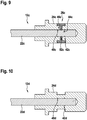
- Fig. 9 shows a schematic representation of an additional embodiment of the lithotripsy device with a probe 12c in a sectional view.
- the present exemplary embodiment essentially differs from the previous one in the design of the probe 12c.
- the probe 12c has a probe head 24c.
- the probe 12c also has a probe rod 22c.
- the probe head 24 and the probe rod 22c are connected to one another in an engagement area 26 of the probe 12c.
- the probe rod 22c has an engaging portion 46c.
- the probe rod 22c has an engaging portion 44c.
- the engaging portion 44c partially forms the engaging portion 26c.
- the probe rod 22c has a profile 42c.
- the profiling 42c is formed by at least two recesses 48c.
- the profiling 42c has an additional recess 48c.
- the additional recess 48c is arranged centrally between the two recesses 48c.
- the probe head 24c has, perpendicular to its main extension axis 28c, a full recess 52c in the area of the engagement section 46c.
- the full recess 52c is intended to be filled with an adhesive. If an engagement section 26c of the probe 12c and an engagement section 26c of the probe head 24c are arranged congruently with one another, the recess 38c is congruent with the additional recess 48c of the profiling 42c.
- the full recess 52c and the additional recess 48c are filled with the adhesive in the case of an adhesive connection of the probe head 24c to the probe rod 22c.
- the probe rod 22c is adhesively connected to the probe head 24c in the manufacture of the present lithotripsy device.
- An adhesive is filled into the recess 38c.
- the adhesive flows into the further recess 48c of the profiling 42c.
- Fig. 10 a schematic representation of a different embodiment of the lithotripsy device with a probe 12d in a sectional view.
- the present The exemplary embodiment differs essentially from the previous one in the design of the probe 12d.
- the probe 12d has a probe head 24d.
- the probe 12d also has a probe rod 22d.
- the probe head 24d has a profile 42d.
- the profiling 42d comprises two recesses 48d arranged offset from one another.
- Fig.11 shows a schematic representation of a particular embodiment of the lithotripsy device with a probe 12e in a sectional view.
- the present exemplary embodiment essentially differs from the preceding one in a configuration of the probe 12e.
- the probe 12e has a probe head 24e.
- the probe 12e also has a probe rod 22e.
- the probe rod 22e has a profile 42e.
- the profile 42e is designed as a thread in the present case. 10
- Ultrasonic actuator 16 amorphous material 56
- Piezo actuator 17th crystalline material 58
- Ultrasonic generator 18th Push unit 110 Process step 20th projectile 112
- Process step 22nd Probe rod 114
- Subprocess step 24 Probe head 116
- Subprocess step 28 Main axis of extension 120
- Ultrasonic horn 124 Process step 34 Lithotripter 36
- Probe tip 38 Recess 40
- Engaging portion 46
- Engaging portion 48 Puncture
Landscapes
- Health & Medical Sciences (AREA)
- Surgery (AREA)
- Engineering & Computer Science (AREA)
- Life Sciences & Earth Sciences (AREA)
- Biomedical Technology (AREA)
- Nuclear Medicine, Radiotherapy & Molecular Imaging (AREA)
- Vascular Medicine (AREA)
- Orthopedic Medicine & Surgery (AREA)
- Mechanical Engineering (AREA)
- Heart & Thoracic Surgery (AREA)
- Medical Informatics (AREA)
- Molecular Biology (AREA)
- Animal Behavior & Ethology (AREA)
- General Health & Medical Sciences (AREA)
- Public Health (AREA)
- Veterinary Medicine (AREA)
- Surgical Instruments (AREA)
Abstract
Description
- Die Erfindung betrifft eine Lithotripsievorrichtung, insbesondere eine intrakorporale Lithotripsievorrichtung, nach dem Oberbegriff des Anspruchs 1.
- Aus der
US 6,875,220 B2 ist bereits eine Lithotripsievorrichtung bekannt, welche eine Zertrümmerungseinheit umfasst, wobei die Zertrümmerungseinheit zur Beseitigung von Konkrementen eingerichteten ist und wenigstens eine zur Beaufschlagung von Konkrementen eingerichtete Sonde, sowie wenigstens eine zumindest mittelbar Impulse auf die Sonde übertragende Impulseinheit umfasst. - Die Aufgabe der Erfindung besteht insbesondere darin, eine gattungsgemäße Vorrichtung mit verbesserten Eigenschaften hinsichtlich einer Effizienz, insbesondere einer Energieeffizienz und/oder einer Bauteileffizienz, bereitzustellen. Die Aufgabe wird erfindungsgemäß durch die Merkmale des Patentanspruchs 1 gelöst, während vorteilhafte Ausgestaltungen und Weiterbildungen der Erfindung den Unteransprüchen entnommen werden können.
- Die Erfindung geht aus von einer Lithotripsievorrichtung, insbesondere einer intrakorporalen Lithotripsievorrichtung, mit einer Zertrümmerungseinheit, welche zur Beseitigung von Konkrementen eingerichteten ist und welche wenigstens eine zur wenigstens mittelbaren Beaufschlagung von Konkrementen eingerichtete Sonde, sowie wenigstens eine zumindest mittelbar Impulse auf die Sonde übertragende Impulseinheit umfasst, welche zur wenigstens mittelbaren Beaufschlagung von Konkrementen einen Sondenstab, sowie zur Aufnahme von Impulsen einen Sondenkopf aufweist.
- In einem Aspekt der Erfindung, welcher insbesondere für sich alleine genommen und/oder in Kombination mit weiteren Aspekten der Erfindung betrachtet werden kann, wird vorgeschlagen, dass die Zertrümmerungseinheit wenigstens teilweise, insbesondere zumindest zu einem Großteil und besonders bevorzugt vollständig, aus einem amorphen Werkstoff besteht, welcher eine Elastizitätsgrenze von wenigstens 1,5% und/oder eine Festigkeit von wenigstens 500 MPa aufweist. Hierdurch kann insbesondere eine Effizienz verbessert werden. Vorteilhaft kann die Nutzung des amorphen Werkstoffs eine Energieübertragung zwischen Bauteilen der Lithotripsievorrichtung und/oder auf die Konkremente verbessert werden, wodurch eine Verbesserung der Energieeffizienz im Betrieb der Lithotripsievorrichtung erzielt werden kann. Weiter vorteilhaft kann durch die Nutzung des amorphen Werkstoffs Abnutzungserscheinungen verringert und/oder eine Standzeit von Komponenten und Bauteilen der Lithotripsievorrichtung erhöht werden, wodurch eine Verbesserung einer Bauteileffizienz erzielt werden kann. Insgesamt kann somit insbesondere gleichzeitig eine Energieeffizienz als auch eine Bauteileffizienz verbessert werden.
- Unter einer "Lithotripsievorrichtung" soll insbesondere ein, vorzugsweise funktionsfähiger Bestandteil, insbesondere eine Unterbaugruppe und/oder eine Konstruktions- und/oder eine Funktionskomponente eines Lithotripters verstanden werden. Vorzugsweise kann die Lithotripsievorrichtung den Lithotripter zumindest teilweise, vorzugsweise zumindest zu einem Großteil und besonders bevorzugt vollständig ausbilden. Die Lithotripsievorrichtung ist zu einer Zertrümmerung von Konkrementen eingerichtet. Unter "Konkrementen" sollen insbesondere sich in Körpern durch Abscheidung entstehende feste Gebilde verstanden werden, welche zumindest teilweise, vorzugsweise zumindest zu einem Großteil und besonders bevorzugt vollständig aus Salzen bestehen, wie beispielsweise Nierensteinen, Gallensteinen, Harnsteinen, Speichelsteinen oder dergleichen. Die Lithotripsievorrichtung ist vorzugsweise als eine intrakorporale Lithotripsievorrichtung ausgebildet, welche dazu ausgebildet ist, zumindest teilweise und vorzugsweise zumindest zu einem Großteil in eine insbesondere künstliche und/oder natürliche Öffnung, insbesondere Körperöffnung, eingeführt zu werden, um dort angesammelte Konkremente zu zertrümmern und/oder zu entfernen. Unter "eingerichtet" soll insbesondere speziell programmiert, ausgelegt, ausgebildet und/oder ausgestattet verstanden werden. Darunter, dass ein Bauteil zu einer bestimmten Funktion eingerichtet ist, soll insbesondere verstanden werden, dass das Bauteil diese bestimmte Funktion in zumindest einem Anwendungs- und/oder Betriebszustand erfüllt und/oder ausführt. Unter dem Ausdruck "zumindest zu einem Großteil" soll dabei insbesondere zumindest zu 55 %, vorzugsweise zumindest zu 65 %, bevorzugt zumindest zu 75 %, besonders bevorzugt zumindest zu 85 % und ganz besonders bevorzugt zumindest zu 95 %, sowie vorteilhaft vollständig verstanden werden und zwar insbesondere mit Bezug auf ein Volumen und/oder eine Masse eines Bauteils. Unter einer "Zertrümmerungseinheit", soll insbesondere eine Einheit verstanden werden, welche sich wenigstens aus der insbesondere intrakorporalen Sonde und der Impulseinheit zusammensetzt. Die Zertrümmerungseinheit kann ferner weitere Einheiten, Komponenten und Bauteile aufweisen. Unter einer "Sonde" soll insbesondere ein stab-, röhren- und/oder schlauchförmiges Bauteil verstanden werden, welches zur Untersuchung und/oder Behandlung eingerichtet ist. Vorzugsweise ist die Sonde als eine intrakorporale Sonde ausgebildet. Unter einer "intrakorporalen Sonde" soll insbesondere eine Sonde, und insbesondere ein Teil der Lithotripsievorrichtung verstanden werden, welche/welcher dazu eingerichtet ist, zumindest teilweise, vorzugsweise zumindest zu einem Großteil und besonders bevorzugt vollständig, in eine insbesondere künstliche und/oder natürliche Öffnung, insbesondere Körperöffnung, eingeführt zu werden, um beispielsweise dort angesammelte Konkremente zu zertrümmern und/oder zu entfernen. Die Sonde weist insbesondere zumindest eine 7 auf, welche dazu eingerichtet ist Konkremente unmittelbar zu kontaktieren, sowie insbesondere Impulse auf diese zu übertragen. Ferner weist die Sonde insbesondere wenigstens einen Sondenkopf auf, welcher zur Aufnahme von den von der Impulseinheit bereitgestellten Impulsen eingerichtet ist. Zudem weist die Sonde insbesondere einen Sondenstab auf, welcher aufgenommene Impulse von dem Sondenkopf zur Sondenspitze zumindest mittelbar überträgt. Unter "zumindest mittelbar" soll insbesondere indirekt aber vorzugsweise auch direkt, also insbesondere unmittelbar, verstanden werden. Vorzugsweise ist der Sondenkopf von dem Sondenstab separat ausgebildet. Es ist jedoch auch denkbar, dass die Sonde zumindest teilweise, vorzugsweise zumindest zu einem Großteil und besonders bevorzugt vollständig einstückig ausgebildet ist. Darunter, dass "ein Bauteil und ein weiteres Bauteil zumindest teilweise einteilig ausgebildet/verbunden sind", soll insbesondere verstanden werden, dass zumindest ein Element und/oder Teil des Bauteils und zumindest ein Element und/oder Teil des weiteren Bauteils einteilig ausgebildet/verbunden sind. Unter "einstückig" soll insbesondere zumindest stoffschlüssig verbunden, beispielsweise durch einen Schweißprozess, einen Klebeprozess, einen Anspritzprozess und/oder einen anderen, dem Fachmann als sinnvoll erscheinenden Prozess, und/oder vorteilhaft in einem Stück geformt verstanden werden, wie beispielsweise durch eine Herstellung aus einem Guss und/oder durch eine Herstellung in einem Ein- oder Mehrkomponentenspritzverfahren und vorteilhaft aus einem einzelnen Rohling. Beispielsweise könnten die Sondenspitze und der Sondenstab einstückig ausgebildet sein. Unter "Impulsen" sollen insbesondere Stoßimpulse und/oder Schwingungsimpulse verstanden werden. Unter einer "Impulseinheit" soll insbesondere eine Einheit verstanden werden, welche zu übertragende Impulse erzeugt und/oder bereitstellt. Unter einem "amorphen Werkstoff soll insbesondere ein Werkstoff verstanden werden, welcher eine unregelmäßige, vorzugsweise nicht kristalline, Anordnung von Atomen aufweist und welche vorteilhaft lediglich über Nahordnung, nicht aber Fernordnung verfügt. Der amorphe Werkstoff weist insbesondere eine Elastizitätsgrenze von wenigstens 1,5%, vorzugsweise von wenigstens 1,75% und besonders bevorzugt von wenigstens 2% und/oder insbesondere von höchstens 2,75%, vorzugsweise von höchstens 2,5 und besonders bevorzugt von höchstens 2,25% auf. Ganz besonders bevorzugt weist der amorphe Werkstoff eine Elastizitätsgrenze von zumindest im Wesentlichen 3% auf. Unter "zumindest im Wesentlichen" in Bezug auf einen Wert einer Wertangabe soll insbesondere verstanden werden, dass der Wert im Rahmen einer Ungenauigkeit von höchstens 15 %, vorzugsweise höchstens 5 % und besonders bevorzugt von höchstens 1 % genau ist oder aber auch frei von einer Ungenauigkeit ist, also vorzugsweise genau ist. Der amorph Werkstoff weist insbesondere eine Festigkeit von wenigstens 500 MPa, vorzugswiese von wenigstens 1000 MPa und besonders bevorzugt von wenigstens 1500 MPa und/oder insbesondere von höchstens 3400 MPa, vorzugsweise von höchstens 2900 MPa und besonders bevorzugt von höchstens 2400 MPa auf. Ganz besonders bevorzugt beträgt eine Festigkeit des amorphen Werkstoffs zumindest im Wesentlichen 2000 MPa. Beispielsweise beträgt ein Verhältnis aus der Elastizitätsgrenze und der Festigkeit des amorphen Werkstoffs wenigstens 400 MPa/%, vorzugsweise wenigstens 600 MPa/% und besonders bevorzugt wenigstens 800 MPa/% und/oder höchstens 1600 MPa/%, vorzugsweise höchstens 1400 MPa/% und besonders bevorzugt höchstens 1200 MPa/%. Ganz besonders bevorzugt beträgt ein Verhältnis der Festigkeit und der Elastizitätsgrenze zumindest im Wesentlichen 1000 MPa/%.
- Beispielsweise sind Hochleistungskunststoffe als amorphe Werkstoffe in der Lage angefordert hohe Elastizitätsgrenzen zu erzielen. Auch sind Hochleistungsmetalllegierungen in der Lage, entsprechend hohe Festigkeiten zu erzielen. Um jedoch insbesondere gleichzeitig eine derartige Elastizitätsgrenze und Festigkeit in Kombination zu erzielen, wird in einer bevorzugten Ausgestaltung der Erfindung vorgeschlagen, dass der amorphe Werkstoff metallisches Glas ist. Es kann vorteilhaft eine Effizienz weiter verbessert werden. Insbesondere weisen metallische Gläser der Anforderung entsprechend hohe Elastizitätsgrenzen auf, welche eine elastische Energieübertragung und somit eine Energieeffizient verbessert. Ferner weisen metallische Gläser der Anforderung entsprechend eine hohe Festigkeit auf, welche die Standzeit und somit die Bauteileffizienz erhöht. Unter "metallischem Glas" soll insbesondere ein Werkstoff verstanden werden, welcher wenigstens ein Metall umfasst, welches in einer amorphen Struktur vorliegt. Auch soll unter metallischem Glas insbesondere amorphes Metall verstanden werden. Das metallische Glas ist vorzugsweise eine Legierung aus Metallen oder Nichtmetallen und Metallen.
- Weiter wird vorgeschlagen, dass der amorphe Werkstoff wenigstens ein Metall, wenigstens ein Übergangsmetall, wenigstens ein Erdalkalimetall und/oder ein Gemisch dieser umfasst. Es kann vorteilhaft eine Festigkeit und/oder Elastizitätsgrenze weiter erhöht werden, wodurch eine Effizienz weiter verbessert werden kann. Bei dem Metall kann es sich insbesondere um Kupfer, Aluminium und/oder dergleichen handeln. Ferner kann es sich bei den Übergangsmetallen um Zirconium, Niob, Titan, Nickel und/oder dergleichen handeln. Ferner kann es sich bei dem Erdalkalimetall um Beryllium, Magnesium und/oder der gleichen handeln. Insbesondere ist der amorphe Werkstoff eine Legierung aus Metallen, Übergangsmetallen und/oder Erdalkalimetallen. Besonders bevorzugt handelt es sich bei dem amorphe Werkstoff um ein metallisches Glas, insbesondere Vitreloy™ 1, Vitreloy™ 1b, Vitreloy™ 4, Vitreloy™ 101, Vitreloy™ 105, Vitreloy™ 106, Vitreloy™ 106a, und/oder AMZ™ 4 bekannt. Das amorphe Material weist dabei beispielsweise eine der folgenden Zusammensetzungen auf:
Vitreloy™ 1: Zr41,2Be22,5Ti13,8Cu12,5Ni10 (at%) Vitreloy™ 1b: Zr44Be25Ti11Cu10Ni10 (at%) Vitreloy™ 4: Zr46,75Ti8;25Cu7,5Ni10Be27,5 (at%) Vitreloy™ 101: Cu47Ti34Zr11Ni8 (at%) Vitreloy™ 105: Zr52,5Cu17,9Ni14,6Al10Ti5 (at%) Vitreloy™ 106: Zr57Cu15,4Ni12,6Al10Nb5 (at%) Vitreloy™ 106a: Zr58,5Cu15,6Ni12,8Al10,3Nb2,8 (at%) AMZ™ 4: Zr59,3Cu28,8Al10,4Nb1,5 (at%) - Der amorphe Werkstoff könnte Kupfer und/oder Titan basiert sein. Darunter, dass der amorphe Werkstoff "auf einem chemischen Element basiert" soll insbesondere verstanden werden, dass dieses chemische Element einen größten Anteil des amorphen Werkstoff ausmacht. Da insbesondere Zirconium basierte amorphe Werkstoffe den Anforderung entsprechend hoher Festigkeiten und Elastizitätsgrenzen aufweisen wird, um vorteilhaft eine Effizienz weiter zu erhöhen in einer bevorzugten Ausgestaltung der Erfindung vorgeschlagen, dass der vorbenannte amorphe Werkstoff Zirconium basiert ist. Beispielsweise bildet Zirconium den größten Anteil bei den amorphen Werkstoffen Vitreloy™ 106 oder AMZ™ 4 aus. Insbesondere besteht der amorphe Werkstoff wenigstens zu 40%, vorzugsweise zu wenigstens 45%, besonders bevorzugt zu wenigstens 50% und ganz besonders bevorzugt zu wenigstens 55% aus Zirconium. Besonders bevorzugt ist der amorphe Werkstoff frei von Beryllium und/oder Niob, wodurch vorteilhaft eine Biokompatibilität des amorphen Werkstoffs verbessert werden kann.
- Es wird weiterhin vorgeschlagen, dass die Sonde wenigstens teilweise, insbesondere zumindest zu einem Großteil und besonders bevorzugt vollständig, aus dem amorphen Werkstoff besteht. Es kann vorteilhaft eine Energieeffizienz weiter erhöht werden. Insbesondere kann eine Energieübertragung zwischen Projektil und Sonde verbessert werden. Vorzugsweise ist die Sonde mehrteilig. Besonders bevorzugt besteht die Sonde höchstens teilweise, also beispielsweise stets weniger als vollständig, aus dem amorphen Werkstoff, wodurch vorteilhaft Kosten eingespart werden können.
- Weiter wird vorgeschlagen, dass der zur Aufnahme von Impulsen eingerichtete Sondenkopf zumindest teilweise, insbesondere zumindest zu einem Großteil und besonders bevorzugt vollständig, aus dem amorphen Werkstoff besteht. Es kann vorteilhaft eine Energieeffizienz noch weiter erhöht werden. Insbesondere kann eine Energieübertragung zwischen Projektil und Sonde weiter verbessert werden. Vorzugsweise ist der Sondenkopf einstückig ausgebildet.
- Des Weiteren wird vorgeschlagen, dass der Sondenstab frei von dem amorphen Werkstoff ist. Es kann vorteilhaft eine Effizienz erhöht werden. Insbesondere kann eine Bauteileffizienz erhöht werden, da mit dem Sondenstab separat aus einem im Vergleich zum amorphen Werkstoff günstigeren Material, wie beispielsweise Stahl, Titan oder dergleichen hergestellt werden kann. Insbesondere kann vermieden werden, dass ein Teil der Sonde, welcher mit einem Patienten in Berührung kommt aus einem nicht biokompatiblen Material besteht. Ferner ist insbesondere die Sondenspitze der Sonde frei von dem amorphen Werkstoff.
- In einem weiteren Aspekt der Erfindung, welcher insbesondere für sich alleine genommen und/oder in Kombination mit weiteren Aspekten der Erfindung betrachtet werden kann, wird vorgeschlagen, dass der Sondenstab und der Sondenkopf form- und/oder kraftschlüssig, insbesondere reibschlüssig, miteinander verbunden sind. Indem eine effiziente Verbindung von Sondenstab und Sondenkopf hergestellt wird, kann vorteilhaft eine Energieübertragung zwischen diesen Bauteilen weiter verbessert werden. Weiter vorteilhaft kann ein ungewolltes Auslösen der Bauteile vermieden werden, wodurch insbesondere eine Standzeit und somit eine Bauteileffizienz verbessert werden kann. Besonders vorteilhaft kann eine Effizienz einer Herstellung und/oder Montage verbessert werden bzw. eine Herstellung und/oder Montage vereinfacht werden. Unter einer "form- und/oder kraftschlüssigen Verbindung" ist insbesondere zu verstehen, verbunden, vorzugsweise lösbar verbunden zu sein, wobei eine Haltekraft zwischen zwei Bauteilen vorzugsweise über einen geometrischen Eingriff der Bauteile ineinander und/oder über eine Reibungskraft, die vorzugsweise zwischen den Bauteilen wirkt, übertragen wird.
- Außerdem wird zudem vorgeschlagen, dass die Sonde einen Eingriffsbereich aufweist, in welchem der Sondenstab und der Sondenkopf miteinander in Eingriff stehen. Durch Schaffung einer festen Verbindung der Bauteile kann eine Energieeffizienz und/oder eine Bauteileffizienz weiter verbessert werden. Insbesondere kann eine Herstellung und/oder Montage vereinfacht werden. Unter einem "Eingriff" soll insbesondere verstanden werden, dass ein Bauteil ein anderes Bauteil von wenigstens drei Seiten umschließt. Unter einer "Seite" soll insbesondere eine gedachte Ebene verstanden werden, welche senkrecht zu einer Koordinatenachse, insbesondere einer Abszissenachse, einer Ordinatenachse und /oder einer Applikatenachse, orientiert ist. Demnach kann ein Bauteil in einem dreidimensionalen Koordinatensystem maximal von sechs Seiten umgeben sein. Denkbar ist, dass sich der Eingriffsbereich einer gesamten Haupterstreckung des Sondenkopfs entspricht. Vorteilhaft ist eine Erstreckung des Eingriffsbereichs jedoch kleiner als eine Haupterstreckung des Sondenkopfs. Unter einer "Haupterstreckung" eines Bauteils soll dabei insbesondere eine längste Erstreckung des Bauteils entlang dessen Haupterstreckungsrichtung verstanden werden. Unter einer "Haupterstreckungsrichtung" eines Bauteils soll dabei insbesondere eine Richtung verstanden werden, welche parallel zu einer längsten Kante eines kleinsten gedachten Quaders verläuft, welcher das Bauteil gerade noch vollständig umschließt. Der Eingriffsbereich ist insbesondere zumindest teilweise von einem Eingriffsabschnitt des Sondenstabs gebildet. Ferner ist der Eingriffsbereich zumindest teilweise von einem Eingriffsabschnitt des Sondenstabs gebildet. Vorzugsweise kann es sich bei der 6 um eine Vollausnehmung handeln.
- Um insbesondere eine stabile und energieeffiziente Energieübertragung zu erzielen, kann vorteilhaft eine Verbindung zwischen Sondenkopf und Sondenstab weiter verbessert werden, indem, wie in einer bevorzugten Ausgestaltung der Erfindung vorgeschlagen, der Eingriffsbereich sich über wenigstens 3 mm, vorzugsweise wenigstens 3,5 mm und besonders bevorzugt wenigstens 4 mm, entlang einer Haupterstreckungsachse des Sondenstab und/oder des Sondenkopfs erstreckt. Ferner erstreckt sich der Eingriffsbereich insbesondere über höchstens 7 mm, vorzugsweise über höchstens 6 mm und besonders bevorzugt über höchstens 5 mm, entlang einer Haupterstreckungsachse des Sondenstab und/oder des Sondenkopfs. Unter einer "Haupterstreckungsachse" soll insbesondere eine Achse verstanden werden, welche parallel zu einer Haupterstreckungsrichtung des Bauteils und insbesondere durch dessen Massen- und/oder geometrischen Mittelpunkt verläuft. Vorzugsweise ist die Erstreckung des Eingriffsbereichs wesentlich kleiner als eine Haupterstreckung des Sondenstab und/oder des Sondenkopfs. Unter "wesentlich kleiner" soll hier insbesondere weniger als die Hälfte verstanden werden.
- Es ist denkbar, dass der Sondenstab den Sondenkopf im Eingriffsbereich umgeben könnte, beispielsweise wenn der Sondenstab über eine Verbreiterung verfügen würde. In einer besonders bevorzugten Ausgestaltung der Erfindung wird jedoch vorgeschlagen, dass im Eingriffsbereich der Sondenkopf den Sondenstab umgibt. Es kann vorteilhaft eine Energieeffizienz und/oder eine Bauteileffizienz weiter verbessert werden. Insbesondere kann eine Herstellung und/oder Montage weiter vereinfacht werden. Insbesondere umgibt der Sondenkopf den Sondenstab von wenigstens vier Seiten. Besonders bevorzugt umgibt der Sondenkopf den Sondenstab von fünf Seiten.
- Ferner wird vorgeschlagen, dass im Eingriffsbereich der Sondenkopf und/oder der Sondenstab profiliert sind. Es kann vorteilhaft eine Energieeffizienz und/oder eine Bauteileffizienz besonders verbessert werden. Insbesondere kann entweder der Sondenkopf oder der Sondenstab profiliert sein. Ferner ist denkbar, dass sowohl der Sondenkopf als auch der Sondenstab profiliert sind. Darunter, dass ein Bauteil profiliert ist" soll insbesondere verstanden werden, dass dieses bereichsweise mit einer Profilierung versehen ist. Vorzugsweise weist die Profilierung eine Undulation, ein Gewinde Einkerbungen, Vorsprünge und/oder dergleichen auf.
- Eine Energieeffizienz und/oder eine Bauteileffizienz kann ganz besonders verbessert werden, wenn der Sondenkopf und der Sondenstab, wie vorgeschlagen, miteinander verpresst, insbesondere vercrimpt, sind. Insbesondere kann eine Herstellung und/oder Montage vereinfacht werden. Vorzugsweise wird der Sondenkopf und/oder der Sondenstab durch verformen miteinander verpresst. Insbesondere ist der Sondenkopf radial mit dem Sondenstab verpresst, insbesondere vercrimpt. Vorzugsweise schneiden im Eingriffsbereich insbesondere ein profilierter Anteil des Sondenkopfs und/oder des Sondenstabs ineinander ein.
- In einem weiteren Aspekt der Erfindung, welcher insbesondere für sich alleine genommen und/oder in Kombination mit weiteren Aspekten der Erfindung betrachtet werden kann, wird vorgeschlagen, dass der Sondenkopf und der Sondenstab miteinander stoffschlüssig verbunden sind. Es kann vorteilhaft eine Energieeffizienz und/oder eine Bauteileffizienz weiter verbessert werden. Unter "stoffschlüssig verbunden" soll insbesondere verstanden werden, dass die Objekte durch atomare oder molekulare Kräfte zusammengehalten werden, wie beispielsweise beim Löten, Schweißen, Kleben und/oder Vulkanisieren.
- In einer Ausgestaltung der Erfindung sind der Sondenkopf und der Sondenstab miteinander verschweißt. In der gleichen oder einer alternativen Ausgestaltung der Erfindung sind der Sondenkopf und der Sondenstab adhäsiv miteinander verbunden. Es kann vorteilhaft eine besonders effiziente Verbindung geschaffen werden.
- Weiterhin wird vorgeschlagen, dass der Sondenkopf und der Sondenstab miteinander umspritzt sind. Es kann vorteilhaft eine effiziente Verbindung geschaffen werden. Insbesondere kann eine Herstellung und/oder Montage vereinfacht werden. Insbesondere ist der Sondenstab von dem Sondenkopf umspritzt. Vorzugsweise bilden Sondenstab und Sondenkopf zusammen eine Mehrkomponenten-Spritzgussbaugruppe aus.
- Außerdem wird vorgeschlagen, dass die Impulseinheit wenigstens eine Stoßeinheit umfasst, welche zur Bereitstellung von Stoßimpulsen wenigstens ein beweglich gelagertes Projektil umfasst, welches dazu eingerichtet ist, die Sonde zumindest mittelbar mit Stoßimpulsen zu beaufschlagen. Es kann vorteilhaft eine Energieeffizienz weiter verbesset werden. Insbesondere kann auf eine effiziente Art und Weise ein Impuls hoher Amplitude zur Zertrümmerung von Konkrementen bereitgestellt und verlustarm übertragen werden. Die Stoßeinheit ist insbesondere dazu eingerichtet, das Projektil mechanisch, pneumatisch, hydraulisch und/oder elektromagnetisch zu beschleunigen, wobei vorzugsweise das Projektil seinen durch die Beschleunigung erfahrenen Impuls zumindest teilweise, vorzugsweise zumindest zu einem Großteil und besonders bevorzugt vollständig, als Stoßimpuls auf die Sonde überträgt.
- Um vorteilhaft eine Energieeffizienz, insbesondere eine Energieübertragung zwischen Projektil und Sonde, weiter zu verbessern, besteht das Projektil insbesondere wenigstens teilweise, vorzugsweise zumindest zu einem Großteil und besonders bevorzugt vollständig, aus dem amorphen Werkstoff. Ganz besonders bevorzugt ist das Projektil einstückig ausgebildet.
- Zudem wird vorgeschlagen, dass die Impulseinheit wenigstens eine Ultraschalleinheit umfasst, welche zur Bereitstellung und Fokussierung von Ultraschallimpulsen wenigstens ein Ultraschallhorn umfasst, welche dazu eingerichtet ist, die Sonde zumindest mittelbar mit Ultraschallimpulsen zu beaufschlagen. Es kann vorteilhaft eine Energieeffizienz weiter verbesset werden. Insbesondere kann auf eine effiziente Art und Weise Impulse hoher Frequenz zur Zertrümmerung von Konkrementen bereitgestellt und verlustarm übertragen werden. Unter einer "Ultraschalleinheit" soll insbesondere eine Einheit verstanden werden, welche dazu ausgebildet ist, Ultraschallimpulse zu erzeugen, bereitzustellen und/oder an ein zu zertrümmerndes Konkrement zu leiten, sowie damit zu beaufschlagen. Unter "Ultraschallimpulse" sollen insbesondere Ultraschallwellen verstanden werden und zwar insbesondere oberhalb eines Hörfrequenzbereichs des Menschen. Im vorliegenden Fall weisen die Ultraschallimpulse insbesondere eine Ultraschallfrequenz von zumindest 10 kHz, vorzugsweise zumindest 15 kHz und besonders bevorzugt zumindest 20 kHz und/oder von höchstens 100 kHz, vorzugsweise von höchstens 80 kHz und besonders bevorzugt von höchstens 56 kHz auf. Ganz besonders bevorzugt beträgt die Ultraschallfrequenz zwischen 22 kHz und 55 kHz. Der Ultraschallgenerator ist insbesondere dabei dazu ausgebildet, Ultraschallimpulse zu erzeugen und vorzugsweise weitere Komponenten der Ultraschalleinheit bereitzustellen. Der Ultraschallgenerator weist insbesondere zumindest einen, vorzugsweise zumindest zwei, besonders bevorzugt zumindest drei und ganz besonders bevorzugt eine Vielzahl von Ultraschallaktoren auf, welcher/welche insbesondere als ein Piezoaktor/Piezoaktoren ausgebildet ist/sind. Insbesondere für den Fall, dass der Ultraschallgenerator zumindest zwei Ultraschallaktoren umfasst, liegen diese zumindest mittelbar aneinander an, um vorteilhaft eine Intensität des erzeugten Ultraschalls zu erhöhen. Der Ultraschallgenerator ist insbesondere mit dem Ultraschallhorn wirkverbunden. Insbesondere um Ultraschallimpulse zu übertragen und zu fokussieren weist das Ultraschallhorn vorzugsweise eine sich vorzugsweise konkav verjüngende Zylinderform auf. Vorzugsweise besteht das Ultraschallhorn zumindest teilweise, vorzugsweise zumindest zu einem Großteil und besonders bevorzugt vollständig aus Metall, wie beispielsweise Eisen, Titan, Stahl oder einer Metalllegierung.
- Es wird weiter vorgeschlagen, dass das Ultraschallhorn wenigstens teilweise, insbesondere zumindest zu einem Großteil und besonders bevorzugt vollständig, aus dem amorphen Werkstoff besteht. Es kann vorteilhaft eine Energieeffizienz und/oder eine Bauteileffizienz weiter verbessert werden.
- In einem weiteren Aspekt der Erfindung wird ein Lithotripter mit wenigstens einer Lithotripsievorrichtung beansprucht. Es kann vorteilhaft ein Lithotripter mit einer erhöhten Effizienz, insbesondere Energieeffizienz und/oder Bauteileffizienz bereitgestellt werden.
- In einem weiteren Aspekt der Erfindung wird ein Verfahren zum Betrieb und/oder zur Herstellung einer Lithotripsievorrichtung beansprucht. Es kann vorteilhaft ein Lithotripsievorrichtung einer erhöhten Effizienz, insbesondere Energieeffizienz und/oder Bauteileffizienz betrieben und/oder hergestellt werden.
- Die erfindungsgemäße Lithotripsievorrichtung, der erfindungsgemäße Lithotripter und/oder das Verfahren zum Betrieb der Lithotripsievorrichtung sowie das erfindungsgemäße Verfahren zur Herstellung der Lithotripsievorrichtung sollen/soll hierbei nicht auf die oben beschriebene Anwendung und Ausführungsform beschränkt sein.
- Insbesondere kann die erfindungsgemäße Lithotripsievorrichtung, der erfindungsgemäße Lithotripter und/oder das Verfahren zum Betrieb der Lithotripsievorrichtung sowie das erfindungsgemäße Verfahren zur Herstellung der Lithotripsievorrichtung zu einer Erfüllung einer hierin beschriebenen Funktionsweise eine von einer hierin genannten Anzahl von einzelnen Elementen, Bauteilen und Einheiten, sowie Verfahrensschritten abweichende Anzahl aufweisen. Zudem sollen bei den in dieser Offenbarung angegebenen Wertebereichen auch innerhalb der genannten Grenzen liegende Werte als offenbart und als beliebig einsetzbar gelten.
- Es wird insbesondere darauf hingewiesen, dass alle in Bezug auf die Lithotripsievorrichtung beschriebenen Merkmale und Eigenschaften aber auch Verfahrensweisen sinngemäß auf das erfindungsgemäße Verfahrens übertragbar und im Sinne der Erfindung einsetzbar und als mitoffenbart gelten. Gleiches gilt auch in umgekehrter Richtung. Das bedeutet, dass auch in Bezug auf das Verfahren genannte, bauliche, also vorrichtungsgemäße Merkmale im Rahmen der Vorrichtungsansprüche berücksichtigt, beansprucht und ebenfalls zur Offenbarung gezählt werden können.
- Falls von einem bestimmten Bauteil mehr als ein Exemplar vorhanden ist, ist nur eines davon in den Figuren und in der Beschreibung mit einem Bezugszeichen versehen. Die Beschreibung dieses Exemplars kann entsprechend auf die anderen Exemplare von dem Bauteil übertragen werden.
- Weitere Vorteile ergeben sich aus der folgenden Zeichnungsbeschreibung. In den Zeichnungen ist ein Ausführungsbeispiel der Erfindung dargestellt. Die Zeichnungen, die Beschreibung und die Ansprüche enthalten zahlreiche Merkmale in Kombination. Der Fachmann wird die Merkmale zweckmäßigerweise auch einzeln betrachten und zu sinnvollen weiteren Kombinationen zusammenfassen.
- Es zeigen:
- Fig. 1
- eine schematische Darstellung eines Lithotripters mit einer Lithotripsievorrichtung in einer perspektivischen Ansicht,
- Fig. 2
- eine schematische Darstellung eines Teils der Lithotripsievorrichtung mit einer Sonde und einer Zertrümmerungseinheit in einer Schnittansicht,
- Fig. 3
- eine schematische Darstellung eines Teils der Sonde mit einem Sondenkopf und einem Sondenstab in einer Schnittansicht,
- Fig. 4
- eine schematische Darstellung einer atomaren Anordnung eines kristallinen Werkstoffs,
- Fig. 5
- eine schematische Darstellung einer atomaren Anordnung eines amorphen Werkstoffs, aus welchem wenigstens teilweise die Zertrümmerungseinheit ausgebildet ist,
- Fig. 6
- einen schematischen Ablaufplan eines beispielhaften Verfahrens zur Herstellung der Lithotripsievorrichtung,
- Fig. 7
- eine schematische Darstellung einer weiteren Ausgestaltung der Lithotripsievorrichtung mit einer Sonde in einer Schnittansicht,
- Fig. 8
- eine schematische Darstellung einer alternativen Ausgestaltung der Lithotripsievorrichtung mit einer Sonde in einer Schnittansicht,
- Fig. 9
- eine schematische Darstellung einer zusätzlichen Ausgestaltung der Lithotripsievorrichtung mit einer Sonde in einer Schnittansicht,
- Fig. 10
- eine schematische Darstellung einer andersartigen Ausgestaltung der Lithotripsievorrichtung mit einer Sonde in einer Schnittansicht und
- Fig. 11
- eine schematische Darstellung einer besonderen Ausgestaltung der Lithotripsievorrichtung mit einer Sonde in einer Schnittansicht.
- Die
Figur 1 zeigt eine schematische Darstellung eines Lithotripters 34 in einer perspektivischen Ansicht. Im vorliegenden Fall ist der Lithotripter 34 als ein intrakorporaler Lithotripter 34 ausgebildet. Der Lithotripter 34 ist dazu eingerichtet zumindest teilweise in Körperöffnungen eingeführt zu werden, um dort angesammelte Konkremente zu zertrümmern und/oder zu entfernen. Der Lithotripter 34 umfasst wenigstens eine Lithotripsievorrichtung. Im vorliegenden Fall bildet die Lithotripsievorrichtung den Lithotripter 34 vollständig aus. Die Lithotriptervorrichtung ist als eine intrakorporale Lithotripsievorrichtung ausgebildet. Alternativ könnte es sich bei dem Lithotripter 34 auch um einen industriellen Lithotripter 34 handeln, welcher beispielsweise zum Zerstören und/oder Dispergieren von Partikeln eingesetzt werden kann. - Die Lithotripsievorrichtung weist eine Zertrümmerungseinheit 10 auf. Die Zertrümmerungseinheit 10 ist zur Beseitigung von Konkrementen eingerichteten. Die Zertrümmerungseinheit 10 weist wenigstens eine Sonde 12 auf. Die Sonde 12 ist dazu eingerichtet Konkremente mit Impulsen zu beaufschlagen. Die Sonde 12 ist im vorliegenden Fall als eine intrakorporale Sonde 12 ausgebildet. Die Sonde 12 ist dazu eingerichtet, um in eine Körperöffnung eingeführt zu werden. Die Sonde 12 ist im vorliegenden Fall stabförmig ausgebildet. Alternativ könnte die Sonde 12 auch röhren und/oder schlauchförmig ausgebildet sein, insbesondere um einen Kanal zum Absaugen und/oder zur Reinigung bereitzustellen.
- Die Sonde 12 weist einen Sondenstab 22 auf. Der Sondenstab 22 ist zur wenigstens mittelbaren Beaufschlagung von Konkrementen eingerichtet. Der Sondenstab 22 überträgt Impulse auf eine Sondenspitze 36 der Sonde 12.
- Die Sondenspitze 36 ist dazu eingerichtet, Konkremente unmittelbar zu kontaktieren. Die Sondenspitze 36 ist dazu eingerichtet, Impulse auf Konkremente zu übertragen. Die Sondenspitze 36 ist an einem distalen Endabschnitt des Sondenstabs 22 angeordnet. Im vorliegenden Fall sind die Sondenspitze 36 und der Sondenstab 22 einstückig ausgebildet. Alternativ könnten die Sondenspitze 36 und der Sondenstab 22 separat voneinander ausgebildet sein. Ferner wäre denkbar, dass die Sondenspitze 36 beweglich am Sondenstab 22 gelagert ist.
- Ferner weist die Sonde 22 zur Aufnahme von Impulsen einen Sondenkopf 24 auf. Der Sondenkopf 24 ist an einem proximalen Endabschnitt des Sondenstabs 22 angeordnet. Der Sondenkopf 24 ist im vorliegenden Fall als eine Hülse ausgebildet.
- Im vorliegenden Fall ist der Sondenkopf 24 separat von dem Sondenstab 22 ausgebildet. Der Sondenstab 22 und der Sondenkopf 24 sind wenigstens form- und kraftschlüssig miteinander verbunden. Alternativ könnte der Sondenkopf 24 auch einstückig mit dem Sondenstab 22 verbunden und/oder ausgebildet sein.
- Der Sondenkopf 24 umschließt den Sondenstab 22 an dem proximalen Endabschnitt des Sondenstabs 22. Der Sondenkopf 24 weist eine Ausnehmung 38 auf. Die Haupterstreckungsachse 40 der Ausnehmung 38 ist im vorliegenden Fall identisch mit der Haupterstreckungsachse 28 des Sondenstabs 22. Ein größter Innendurchmesser der Ausnehmung 38 ist zumindest im Wesentlichen identisch zu einem kleinsten Außendurchmesser des Sondenstabs 22.
- Die Ausnehmung 38 ist eine Teilausnehmung. Die Ausnehmung 38 durchstößt den Sondenstab 22 höchstens teilweise. Die Ausnehmung 38 ist als ein Sackloch ausgebildet. Die Ausnehmung 38 weist eine Haupterstreckungsachse 40 auf. Der Sondenstab 22 ist im Bereich des Endabschnitts in der Ausnehmung 38 angeordnet. Alternativ könnte die Ausnehmung 38 auch eine Vollausnehmung 52 sein und sich vorteilhaft durch die gesamte Erstreckung des Sondenkopfs 24 erstrecken. Ferner könnte sich der Sondenstab 22 wenigstens teilweise über den Sondenkopf 24 heraus erstrecken.
- Die Sonde 12 weist einen Eingriffsbereich 26 auf. Im Eingriffsbereich 26 umgibt der Sondenkopf 24 den Sondenstab 22. Der Sondenstab 22 und der Sondenkopf 24 stehen in dem Eingriffsbereich 26 miteinander in Eingriff. Der Eingriffsbereich 26 erstreckt sich über wenigstens 3 mm entlang einer Haupterstreckungsachse 28 des Sondenstabs 22 und/oder des Sondenkopfs 24.
- Der Sondenstab 22 weist einen Eingriffsabschnitt 44 auf. Ferner weist der Sondenkopf 24 einen Eingriffsabschnitt 46 auf. Der Eingriffsbereich 26 ist zumindest von dem Eingriffsabschnitt 44 des Sondenstabs 22 und dem Eingriffsabschnitt 46 des Sondenkopfs 24 gebildet. In einem montierten Zustand sind der Sondenkopf 24 und der Sondenstab 22 so zueinander angeordnet, dass der Eingriffsabschnitt 44 des Sondenstabs 22 und der Eingriffsabschnitt 46 des Sondenkopfs 24 zueinander deckungsgleich zueinander angeordnet sind und derart den Eingriffsbereich 26 ausbilden.
- Der Eingriffsabschnitt 46 des Sondenkopfs 24 erstreckt sich wenigstens über einen Teil der Ausnehmung 38. Ferner ist denkbar, dass sich der Eingriffsabschnitt 46 über die gesamte Ausnehmung 38 erstreckt. Eine Haupterstreckung des Eingriffsbereichs 26 ist kleiner als eine Haupterstreckung des Sondenkopfs 24. Ferner ist der Eingriffsbereich 26 kleiner als eine Haupterstreckung der Ausnehmung 38.
- Im vorliegenden Fall ist der Sondenstab 22 im Eingriffsbereich 26 profiliert. Der Eingriffsabschnitt 44 des Sondenstabs 22 weist wenigstens eine Profilierung 42 auf. Die Profilierung 42 weist wenigstens einen Einstich 48 auf. Bei dem Einstich 48 handelt es sich um einen radialen Einstich 48. Ferner umfasst die Profilierung 42 wenigstens einen weiteren Einstich 48. Der weitere Einstich 48 ist zum Dienst im Wesentlichen identisch zu dem Einstich 48 ausgebildet. Im vorliegenden Fall umfass die Profilierung 42 zwei Einstiche 48. Der weitere Einstich 48 ist entlang der Haupterstreckung des Sondenstabs 22 versetzt zu dem Einstich 48 angeordnet. Ferner könnte der Eingriffsabschnitt 44 des Sondenstabs 22 als Profilierung 42 ein Gewinde, Zähne oder dergleichen aufweisen. Alternativ oder zusätzlich könnte der Sondenkopf 24 im Eingriffsbereich 26 profiliert sein. Dazu könnte der Eingriffsabschnitt 46 des Sondenkopfs 24 eine Profilierung 42 aufweisen. Insbesondere könnte die Profilierung 42 des Eingriffsabschnitts 46 des Sondenkopfs 24 korrespondierend zu der Profilierung 42 des Eingriffsabschnitts 44 des Sondenstabs 22 ausgebildet sein.
- Der Sondenkopf 24 weist im Bereich des Eingriffsabschnitts 46 eine verringerte Wandstärke auf. Der Sondenkopf 24 weist wenigstens eine erste Wandstärke auf. Ferner weist der Sondenkopf 24 wenigstens eine zweite Wandstärke auf. Die zweite Wandstärke ist dem Eingriffsabschnitt 44 zugeordnet.
- Der Sondenstab 22 und der Sondenkopf 24 sind in einem montierten Zustand durch eine Pressfassung miteinander verbunden. Im vorliegenden Fall ist die Pressfassung eine thermische Pressfassung. Bei der thermischen Pressfassung sind der Sondenstab 22 und der Sondenkopf 24 durch nacheinander Erhitzen und/oder Abkühlen ineinander gefasst und miteinander verbunden. Ferner sind der Sondenstab 22 und der Sondenkopf 24 in einem montierten Zustand axial miteinander im Eingriffsbereich 26 miteinander verpresst. Alternativ oder zusätzlich sind in einem montierten Zustand der Sondenkopfs 24 und des Sondenstabs 22 etwaige Hohlräume und/oder Fugen mit einem Adhäsiv verfüllt.
- Ferner weist die Zertrümmerungseinheit 10 wenigstens eine Impulseinheit 14 auf. Die Impulseinheit 14 ist dazu eingerichtet, wenigstens mittelbar Impulse auf die Sonde 12 zu übertragen. Die Impulseinheit 14 weist wenigstens eine Ultraschalleinheit 30 auf. Die Ultraschalleinheit 30 weist wenigstens ein Ultraschallhorn 32 auf. Das Ultraschallhorn 32 dient zur Bereitstellung und Fokussierung von Ultraschallimpulsen. Das Ultraschallhorn 32 ist dazu eingerichtet, die Sonde 12 zumindest mittelbar mit Ultraschallimpulsen zu beaufschlagen. Das Ultraschallhorn 32 weist die Form eines Rotationskörpers auf. Im vorliegenden Fall weist das Ultraschallhorn 32 eine hohlzylinderartige Form auf. Das Ultraschallhorn 32 besteht zumindest teilweise aus Metall, insbesondere Stahl oder Titan.
- Die Sonde 12 ist an dem Ultraschallhorn 32 angeordnet. Die Sonde 12 ist mit dem Ultraschallhorn 32 kraft- und/oder formschlüssig verbunden. Im vorliegenden Fall weist das Ultraschallhorn 32 ein Innengewinde auf. Die Sonde 12 weist ein Außengewinde auf. Das Innengewinde der Sonde 12 ist an einer Außenseite des Sondenkopfs 24 angeordnet. Derart ist die Sonde 12 in einem montierten Zustand in das Ultraschallhorn 32 eingedreht.
- Die Ultraschalleinheit 30 weist wenigstens einen Ultraschallgenerator 58 auf. Der Ultraschallgenerator 58 ist dazu eingerichtet Ultraschallimpulse bereitzustellen. Der Ultraschallgenerator 58 weist wenigstens einen Ultraschallaktor 54 auf. Im vorliegenden Fall weist der Ultraschallgenerator 58 mehrere Ultraschallaktoren 54 auf. Der Ultraschallgenerator 58 weist drei Ultraschallaktoren 54 auf. Die Ultraschallaktoren 54 sind aneinander anliegend gestapelt angeordnet. Der Übersichtlichkeit halber ist in den Zeichnungen nur ein Ultraschallaktor 54 mit einem Bezugszeichen versehen. Die Ultraschallaktoren 54 sind zumindest im Wesentlichen identisch zueinander ausgebildet. Im Folgenden ist nur ein Ultraschallaktor 54 näher beschrieben. Diese Beschreibung ist auch auf die weiteren Ultraschallaktoren 54 übertragbar. Der Ultraschallaktor 54 weist die Form eines Hohlzylinders auf. Im vorliegenden Fall ist der Ultraschallaktor 54 als ein Piezoaktor 56 ausgebildet. Im vorliegenden Fall sind der Übersichtlichkeit halber etwaige Anschluss- und/oder Kontaktierungsmittel und/oder Isolationen der Ultraschallaktoren 54 nicht dargestellt.
- Die Impulseinheit 14 weist wenigstens eine Stoßeinheit 18 auf. Die Stoßeinheit 18 ist zu Bereitstellung von Stoßimpulsen eingerichtet. Die Stoßeinheit 18 umfasst wenigstens ein beweglich gelagertes Projektil 20. Das Projektil 20 ist dazu eingerichtet, die Sonde 12 zumindest mittelbar mit Stoßimpulsen zu beaufschlagen. Die Stoßeinheit 18 ist dazu eingerichtet das Projektil 20 zu beschleunigen. Im vorliegenden Fall beschleunigt die Stoßeinheit 18 das Projektil 20 pneumatisch. Dazu weist die Stoßeinheit 18 einen Projektilkanal auf. In dem Projektilkanal ist das Projektil 20 angeordnet. Das Projektil 20 liegt fluiddicht an einer Wandung des Projektilkanals an. Ferner weist die Stoßeinheit 18 einen Fluidanschluss auf. Der Fluidanschluss ist fluidtechnisch mit dem Projektilkanal verbunden. Der Fluidanschluss ist mit einer Pneumatikeinheit der Lithotripsievorrichtung verbunden, welches der Stoßeinheit 18 pneumatische Energie in Form von Pressluft zur Verfügung stellt. Derart kann das Projektil 20 durch Pressluft innerhalb des Projektilkanals beschleunigt werden. Trifft das Projektil 20 auf die Sonde 12 überträgt das Projektil 20 seinen durch die Beschleunigung erfahrenen Impuls als Stoßimpuls zumindest zu einem Großteil auf die Sonde 12. Alternativ oder zusätzlich könnte die Stoßeinheit 18 zur mechanischen, hydraulischen und/oder elektromagnetischen Beschleunigung des Projektils 20 eingerichtet sein.
- Die Zertrümmerungseinheit 10 besteht wenigstens teilweise aus einem amorphen Werkstoff 16. In
Fig. 5 ist eine schematische Darstellung einer strukturellen Anordnung von Atomen in dem amorphen Werkstoff 16 gezeigt. Im Vergleich dazu zeigtFig. 4 eine schematische Darstellung einer strukturellen Anordnung von Atomen in einem von dem amorphen Werkstoff 16 verschiedenen kristallinen Werkstoff 17. - Der amorphe Werkstoff 16 weist eine Elastizitätsgrenze von wenigstens 1,5% auf. Ferner weist der amorphe Werkstoff 16 eine Festigkeit von wenigstens 500 MPa auf. Der amorphe Werkstoff 16 ist metallisches Glas ist. Der amorphe Werkstoff 16 weist wenigstens ein Metall auf. Im vorliegenden Fall weist der amorphe Werkstoff 16 als Metalle Kupfer und Aluminium auf. Ferner weist der amorphe Werkstoff 16 wenigstens ein Übergangsmetall auf. Im vorliegenden Fall weist der vorliegende amorphe Werkstoff 16 als Übergangsmetalle wenigstens Zirconium, Titan und Nickel auf. Der amorphe Werkstoff 16 umfasst also ein Gemisch aus Metallen und Übergangsmetallen. Im vorliegenden Fall ist der amorphe Werkstoff 16 frei von Erdalkalimetallen. Alternativ könnte der amorphe Werkstoff 16 auch Erdalkalimetalle umfassen.
- Der amorphe Werkstoff 16 ist im vorliegenden Fall Zirconium basiert. Zirconium bildet einen größten Anteil des amorphen Werkstoffs 16 aus. Der amorphe Werkstoff 16 weist wenigstens 40 % Zirconium auf. Im vorliegenden Fall weist der amorphe Werkstoff 16 sogar wenigstens 50 % Zirconium auf. Alternativ könnte der amorphe Werkstoff 16 auch Kupfer und/oder Titan basiert sein. Im vorliegenden Fall ist als amorpher Werkstoff 16 Zr52,5Cu17,9Ni14,6Al10Ti5 (at%) gewählt. Der amorphe Werkstoff 16 ist bekannt unter dem Markennamen Vitreloy™ 105. Alternativ könnte auch ein anderer amorpher Werkstoff 16 genutzt werden.
- Die Sonde 12 besteht wenigstens teilweise aus dem amorphen Werkstoff 16. Der Sondenkopf 24 besteht zumindest teilweise aus dem amorphen Werkstoff 16. Im vorliegenden Fall besteht der Sondenkopf 24 sogar vollständig aus dem amorphen Werkstoff 16. Der Sondenstab 22 hingegen ist im vorliegenden Fall frei von dem amorphen Werkstoff 16. Alternativ oder zusätzlich könnte auch der Sondenstab 22 zumindest teilweise aus dem amorphen Werkstoff 16 bestehen.
- Die Impulseinheit 14 besteht wenigstens teilweise aus dem amorphen Werkstoff 16. Im vorliegenden Fall besteht die Stoßeinheit 18 der Impulseinheit 14 wenigstens teilweise aus dem amorphen Werkstoff 16. Das Projektil 20 der Stoßeinheit 18 besteht wenigstens teilweise aus dem amorphen Werkstoff 16. Im vorliegenden Fall besteht das Projektil 20 sogar vollständig aus dem amorphen Werkstoff 16. Alternativ oder zusätzlich könnte die Ultraschalleinheit 30 wenigstens teilweise aus dem amorphen Werkstoff 16 bestehen. Beispielsweise kann das Ultraschallhorn 32 der Ultraschalleinheit 30 wenigstens teilweise aus dem amorphen Werkstoff 16 bestehen.
-
Fig. 6 zeigt einen schematischen Ablaufplan eines beispielhaften Verfahrens zur Herstellung der Lithotripsievorrichtung. In dem Verfahren wird die Zertrümmerungseinheit 10 wenigstens teilweise aus dem amorphen Werkstoff 16 ausgebildet. - Das Verfahren umfasst wenigsten einen Verfahrensschritt 110. In dem Verfahrensschritt 110 werden die aus dem amorphen Werkstoff 16 bestehenden Komponenten der Zertrümmerungseinheit 10 hergestellt. Als Komponenten werden zumindest die Sonde 12 und/oder die Impulseinheit 14 aus dem amorphen Werkstoff 16 hergestellt. Bei der vorliegenden Sonde 12 wird wenigstens der Sondenkopf 24 zumindest teilweise aus dem amorphen Werkstoff 16 hergestellt. Bei der vorliegenden Impulseinheit 14 werden ferner die Stoßeinheit 18 und/oder die Ultraschalleinheit 30 zumindest teilweise aus dem amorpher Werkstoff 16 hergestellt. Aus dem amorphen Werkstoff 16 wird das Projektil 20 der Stoßeinheit 18 hergestellt. Ferner könnte das Ultraschallhorn 32 wenigstens teilweise aus dem amorphen Werkstoff 16 hergestellt werden. Im vorliegenden Fall werden die Komponenten durch Urformen, insbesondere Spritzgießen hergestellt. Alternativ oder zusätzlich könnten die Komponenten auch durch Laserschmelzen, Lasersintern oder dergleichen hergestellt werden.
- Das Verfahren umfasst wenigstens einen weiteren Verfahrensschritt 112. In dem weiteren Verfahrensschritt 112 werden aus dem amorphen Material hergestellte Komponenten mit weiteren Bauteilen der Lithotripsievorrichtung verbunden. Beispielsweise wird der Sondenkopf 24 wird mit dem Sondenstab 22 verbunden.
- Der Verfahrensschritt 112 umfasst wenigstens einen Teilverfahrensschritt 114. In dem Teilverfahrensschritt 114 wird der Sondenkopf 24 form- und/oder kraftschlüssig mit dem Sondenstab 22 verbunden. Diese werden mittels einer Pressfassung miteinander verbunden. Im vorliegenden Fall ist die Pressfassung eine thermische Pressfassung. Der Sondenkopf 24 wird im Verhältnis zu der Temperatur des Sondenstabs 22 erhitzt. Durch Erhitzen des Sondenkopfs 24 wird die Ausnehmung 38 des Sondenkopfs 24 geweitet, sodass der Sondenstab 22 in diesen eingeführt werden kann. Der Sondenstab 22 wird in den Sondenkopf 24 soweit eingeführt, dass der Eingriffsabschnitt 44 des Sondenstabs 22 deckungsgleich mit dem Eingriffsabschnitt 46 des Sondenkopfs 24 angeordnet ist. Ist die Ausnehmung 38 als ein Sackloch ausgebildet wird der Sondenstab 22 ferner soweit in den Sondenkopf 24 eingeführt, bis dieser an eine Endfläche der Ausnehmung 38 anstößt. Der Sondenkopf 24 wird abgekühlt, wodurch sich dessen Ausnehmung 38 verengt. Der Sondenstab 22 wird mit dem Sondenkopf 24 radial verpresst. Dadurch werden der Sondenkopf 24 und der Sondenstab 22 ineinander verkeilt. Dabei greift die Profilierung 42 des Endabschnitts des Sondenstabs 22 in den Endabschnitt 46 des Sondenkopfs 24 ein. Im Endabschnittsbereich 26 greifen somit der Sondenkopf 24 und der Sondenstab 22 ineinander ein.
- Der Verfahrensschritt 112 kann einen weiteren Teilverfahrensschritt 116 umfassen. Dieser kann zusätzlich oder alternativ zu dem Teilverfahrensschritt 114 durchgeführt werden. Der in dem Sondenkopf 24 eingeführte Sondenstab 22 wird wenigstens im Eingriffsbereich 26 radial mit einer externen Kraft beaufschlagt, wodurch dieser im Eingriffsbereich 26 mit dem Sondenstab 22 vercrimpt wird.
- Der Verfahrensschritt 112 kann einen weiteren Teilverfahrensschritt 118 umfassen. Dieser kann zusätzlich oder alternativ zu dem Teilverfahrensschritt 114 und/oder zu dem Teilverfahrensschritt 116 durchgeführt werden. In diesem Teilverfahrensschritt 118 werden der ineinander eingeführte Sondenstab 22 und Sondenkopf 24 stoffschlüssig miteinander verbunden. Dazu wird ein Adhäsiv genutzt, mittels welchem Fugen und/oder Ausnehmungen der Sonde 12, insbesondere zwischen dem Sondenstab 22 und dem Sondenkopf 24 gefüllt werden.
- Der Verfahrensschritt 112 kann einen weiteren Teilverfahrensschritt 120 umfassen. Dieser kann zusätzlich oder alternativ zu dem Teilverfahrensschritt 114, zu dem Teilverfahrensschritt 116 und/oder zu dem Teilverfahrensschritt 118 durchgeführt werden. Ferner kann der Teilverfahrensschritt 120 gleichzeitig mit dem Teilverfahrensschritt 114, mit dem Teilverfahrensschritt 116 und/oder mit dem Teilverfahrensschritt 118 ausgeführt werden. In dem Teilverfahrensschritt 120 wird der Sondenkopf 24 gleichzeitig Hergestellt und mit dem Sondenstab 22 form- und/oder kraftschlüssig mit dem Sondenkopf 24 verbunden. Der Sondenstab 22 wird mit dem Sondenkopf 24 umspritzt.
- Das Verfahren umfasst wenigstens einen weiteren Verfahrensschritt 122. In dem weiteren Verfahrensschritt 122 werden die zuvor aus dem amorphen Werkstoff 16 hergestellt und/oder verbundenen Komponenten mit weiteren Komponenten der Lithotripsievorrichtung verbunden. Die Sonde 12 wird mit dem Ultraschallhorn 32 verbunden. Ferner wir das Projektil 20 in den Projektilkanal eingelegt.
- Das Verfahren umfasst wenigstens einen weiteren Verfahrensschritt 124. In dem weiteren Verfahrensschritt 124 wird die Impulseinheit 14 in einem Gehäuse angeordnet.
- In den
Figuren 7 bis 11 sind Ausführungsbeispiele der Erfindung gezeigt. Die nachfolgenden Beschreibungen und die Zeichnungen beschränken sich im Wesentlichen auf die Unterschiede zwischen den Ausführungsbeispielen, wobei bezüglich gleich bezeichneter Bauteile, insbesondere in Bezug auf Bauteile mit gleichen Bezugszeichen, grundsätzlich auch auf die Zeichnungen und/oder die Beschreibung der anderen Ausführungsbeispielen, insbesondere derFiguren 1 bis 6 verwiesen wird. Zur Unterscheidung der weiteren Ausführungsbeispiele derFiguren 7 bis 11 ist den Bezugszeichen die Buchstaben a, b, c, d und e nachgestellt, wobei sich gleiche Bezugszeichen auf die entsprechenden Bauteile des vorhergehenden Ausführungsbeispiels beziehen. -
Fig.7 zeigt eine schematische Darstellung einer weiteren Ausgestaltung der Lithotripsievorrichtung mit einer Sonde 12a in einer Schnittansicht. Das vorliegende Ausführungsbeispiel unterscheidet sich im Wesentlichen von dem Vorhergehenden durch eine Ausgestaltung der Sonde 12a. - Im vorliegenden Fall weist ein Sondenkopf 24a der Sonde 12a eine Ausnehmung 38a auf, welche als eine Vollausnehmung 52a ausgebildet ist. Der Sondenstab 22a weist eine Verbreiterung 50a auf. Die Verbreiterung 50a ist an einem proximalen Endabschnitt des Sondenstabs 22a angeordnet. Die Verbreiterung 50a bildet einen Anschlag aus. Mittels der Verbreiterung 50a liegt der Sondenstab 22a stirnseitig an einer proximalen Seite des Sondenkopfs 24a an. Durch das Anliegen der Verbreiterung 50a an der proximalen Stirnseite des Sondenkopfs 24a kann zusätzlich ein ungewolltes Auslösen der Verbindung zwischen Sondenkopf 24a und Sondenstab 22a vermieden werden. Vorteilhaft kann vermieden werden, dass sich im Betrieb der Sondenstab 22a in Distalrichtung löst, wobei er wohlmöglich in einem Patienten stecken bleiben könnte.
- Alternativ oder zusätzlich zu dem Verfahren des vorhergehenden Ausführungsbeispiels wird bei der Herstellung der vorliegenden Lithotripsievorrichtung der Sondenstab 22a proximalseitig in den Sondenkopf 24a eingeführt. Stößt die Verbreiterung 50a an die proximale Stirnseite des Sondenstabs 22a an, so sind Eingriffsabschnitte 44a, 46a des Sondenstabs 22a und des Sondenkopf 24a miteinander deckungsgleich angeordnet. Die Verbreiterung 50a des Sondenstabs 22a könnte mittels Urformen hergestellt werden. Vorzugsweise wird die Verbreiterung 50a jedoch durch Umformen, wie beispielsweise dengeln erzielt.
-
Fig.8 zeigt eine schematische Darstellung einer alternativen Ausgestaltung der Lithotripsievorrichtung mit einer Sonde 12b in einer Schnittansicht. Das vorliegende Ausführungsbeispiel unterscheidet sich im Wesentlichen von dem vorhergehenden durch eine Ausgestaltung der Sonde 12b. - Die Sonde 12b weist einen Sondenkopf 24b auf. Ferner weist die Sonde 12b einen Sondenstab 22b auf. Im vorliegenden Fall ist der Sondenstab 22b und der Sondenkopf 24b miteinander stoffschlüssig verbunden. Die Sonde 12b weist einen Eingriffsbereich 26b auf. Der Sondenstab 22b weist einen Eingriffsabschnitt 44b auf. Der Eingriffsabschnitt 44b bildet den Eingriffsbereich 26b teilweise aus. In dem Eingriffsabschnitt 44b weist der Sondenstab 22b eine Profilierung 42b auf. Die Profilierung 42b ist im vorliegenden Fall in von wenigstens zwei Einstichen 48b ausgebildet. Ferner weist der Sondenkopf 24b einen Eingriffsabschnitt 46b auf. Der Eingriffsabschnitt 46b bildet zumindest teilweise den Eingriffsbereich 26b aus.
- Alternativ oder zusätzlich zu dem Verfahren des vorhergehenden Ausführungsbeispiels wird bei der Herstellung der vorliegenden Lithotripsievorrichtung der Sondenstab 22b mit dem Sondenkopf 24b umgossen. Ferner könnte auch der Sondenstab 22b in den Sondenkopf 24b hineingegossen werden. Das Material des Sondenkopfs 24b umgibt die Profilierung 42b des Eingriffsabschnitts 46b des Sondenkopfs 24b. Das Material des Sondenkopfs 24b verfüllt die Einstiche 48b.
-
Fig. 9 zeigt eine schematische Darstellung einer zusätzlichen Ausgestaltung der Lithotripsievorrichtung mit einer Sonde 12c in einer Schnittansicht. Das vorliegende Ausführungsbeispiel unterscheidet sich im Wesentlichen von dem vorhergehenden durch eine Ausgestaltung der Sonde 12c. - Die Sonde 12c weist einen Sondenkopf 24c auf. Ferner weist die Sonde 12c einen Sondenstab 22c auf. In einem Eingriffsbereich 26 der Sonde 12c sind der Sondenkopf 24 und der Sondenstab 22c miteinander verbunden. Der Sondenstab 22c weist einen Eingriffsabschnitt 46c auf. Der Sondenstab 22c weist einen Eingriffsabschnitt 44c auf. Der Eingriffsabschnitt 44c bildet den Eingriffsbereich 26c teilweise aus. In dem Eingriffsabschnitt 44c weist der Sondenstab 22c eine Profilierung 42c auf. Die Profilierung 42c ist im vorliegenden Fall in von wenigstens zwei Einstichen 48c ausgebildet. Ferner weist die Profilierung 42c einen zusätzlichen Einstich 48c auf. Der zusätzliche Einstich 48c ist mittig zwischen den beiden Einstichen 48c angeordnet.
- Der Sondenkopf 24c weist senkrecht zu seiner Haupterstreckungsachse 28c eine Vollausnehmung 52c im Bereich des Eingriffsabschnitts 46c auf. Die Vollausnehmung 52c ist zu einer Verfüllung mit einem Adhäsiv vorgesehen. Sind ein Eingriffsabschnitt 26c der Sonde 12c und ein Eingriffsabschnitt 26c des Sondenkopfs 24c miteinander deckungsgleich angeordnet, liegt die Ausnehmung 38c deckungsgleich zu dem zusätzlichen Einstich 48c der Profilierung 42c. Die Vollausnehmung 52c und der zusätzliche Einstich 48c sind bei einer adhäsiven Verbindung des Sondenkopfs 24c mit dem Sondenstab 22c mit dem Adhäsiv verfüllt.
- Alternativ oder zusätzlich zu dem Verfahren der vorhergehenden Ausführungsbeispiele wird bei der Herstellung der vorliegenden Lithotripsievorrichtung der Sondenstab 22c mit dem Sondenkopf 24c adhäsiv verbunden. Ein Adhäsiv wird in die Ausnehmung 38c eingefüllt. Dabei fließt das Adhäsiv in den weiteren Einstich 48c der Profilierung 42c.
-
Fig.10 eine schematische Darstellung einer andersartigen Ausgestaltung der Lithotripsievorrichtung mit einer Sonde 12d in einer Schnittansicht. Das vorliegende Ausführungsbeispiel unterscheidet sich im Wesentlichen von dem vorhergehenden durch eine Ausgestaltung der Sonde 12d. - Die Sonde 12d weist einen Sondenkopf 24d auf. Ferner weist die Sonde 12d einen Sondenstab 22d auf. Im vorliegenden Fall weist der Sondenkopf 24d eine Profilierung 42d auf. Die Profilierung 42d umfasst zwei versetzt zueinander angeordnete Einstiche 48d.
-
Fig.11 zeigt eine schematische Darstellung einer besonderen Ausgestaltung der Lithotripsievorrichtung mit einer Sonde 12e in einer Schnittansicht. Das vorliegende Ausführungsbeispiel unterscheidet sich im Wesentlichen von dem Vorhergehenden durch eine Ausgestaltung der Sonde 12e. - Die Sonde 12e weist einen Sondenkopf 24e auf. Ferner weist die Sonde 12e beinen Sondenstab 22e auf. Im vorliegenden Fall weist der Sondenstab 22e eine Profilierung 42e auf. Die Profilierung 42e ist im vorliegenden Fall als ein Gewinde ausgebildet.
10 Zertrümmerungseinheit 50 Verbreiterung 12 Sonde 52 Vollausnehmung 14 Impulseinheit 54 Ultraschallaktor 16 amorpher Werkstoff 56 Piezoaktor 17 kristalliner Werkstoff 58 Ultraschallgenerator 18 Stoßeinheit 110 Verfahrensschritt 20 Projektil 112 Verfahrensschritt 22 Sondenstab 114 Teilverfahrensschritt 24 Sondenkopf 116 Teilverfahrensschritt 26 Eingriffsbereich 118 Teilverfahrensschritt 28 Haupterstreckungsachse 120 Teilverfahrensschritt 30 Ultraschalleinheit 122 Verfahrensschritt 32 Ultraschallhorn 124 Verfahrensschritt 34 Lithotripter 36 Sondenspitze 38 Ausnehmung 40 Haupterstreckungsachse 42 Profilierung 44 Eingriffsabschnitt 46 Eingriffsabschnitt 48 Einstich
Claims (21)
- Lithotripsievorrichtung, insbesondere intrakorporale Lithotripsievorrichtung, mit wenigstens einer Zertrümmerungseinheit (10), welche zur Beseitigung von Konkrementen eingerichtet ist und welche wenigstens eine zur Beaufschlagung von Konkrementen eingerichtete Sonde (12a-e), sowie wenigstens eine zumindest mittelbar Impulse auf die Sonde (12a-e) übertragende Impulseinheit (14) umfasst, welche zur wenigstens mittelbaren Beaufschlagung von Konkrementen einen Sondenstab (22a-e), sowie zur Aufnahme von Impulsen einen Sondenkopf (24a-e) aufweist, dadurch gekennzeichnet, dass die Zertrümmerungseinheit (10) wenigstens teilweise aus einem amorphen Werkstoff (16) besteht, welcher eine Elastizitätsgrenze von wenigstens 1,5% und/oder eine Festigkeit von wenigstens 500 MPa aufweist.
- Lithotripsievorrichtung nach Anspruch 1, dadurch gekennzeichnet, dass der amorphe Werkstoff (16) metallisches Glas ist.
- Lithotripsievorrichtung nach Anspruch 1 oder 2, dadurch gekennzeichnet, dass der amorphe Werkstoff (16) wenigstens ein Metall, wenigstens ein Übergangsmetall, wenigstens ein Erdalkalimetall und/oder ein Gemisch dieser umfasst.
- Lithotripsievorrichtung nach einem der vorhergehenden Ansprüche, dadurch gekennzeichnet, dass der amorphe Werkstoff (16) Zirconium basiert ist.
- Lithotripsievorrichtung nach einem der vorhergehenden Ansprüche, dadurch gekennzeichnet, dass die Sonde (12a-e) wenigstens teilweise aus dem amorphen Werkstoff (16) besteht.
- Lithotripsievorrichtung nach einem der vorhergehenden Ansprüche, dadurch gekennzeichnet, dass der Sondenkopf (24a-e) zumindest teilweise aus dem amorphen Werkstoff (16) besteht.
- Lithotripsievorrichtung nach einem der vorhergehenden Ansprüche, dadurch gekennzeichnet, dass der Sondenstab (22a-e) frei von dem amorphen Werkstoff (16) ist.
- Lithotripsievorrichtung zumindest nach dem Oberbegriff von Anspruch 1 und insbesondere nach einem der vorhergehenden Ansprüche, dadurch gekennzeichnet, dass der Sondenstab (22a-e) und der Sondenkopf (24a-e) wenigstens form- und/oder kraftschlüssig, insbesondere reibschlüssig, miteinander verbunden sind.
- Lithotripsievorrichtung nach Anspruch 8, dadurch gekennzeichnet, dass die Sonde (12a-e) einen Eingriffsbereich (26b; 26c) aufweist, in welchem der Sondenstab (22a-e) und der Sondenkopf (24a-e) miteinander in Eingriff stehen.
- Lithotripsievorrichtung nach Anspruch 9, dadurch gekennzeichnet, dass der Eingriffsbereich (26b; 26c) sich über wenigstens 3 mm entlang einer Haupterstreckungsachse (28c/40c) des Sondenstabs (22a-e) und der Sondenkopfs (24a-e) erstreckt.
- Lithotripsievorrichtung nach 8 oder 9, dadurch gekennzeichnet, dass im Eingriffsbereich (26b: 26c) der Sondenkopf (24a-e) den Sondenstab (22a-e) umgibt.
- Lithotripsievorrichtung nach einem der Ansprüche 8 bis 10, dadurch gekennzeichnet, dass im Eingriffsbereich (26b,c) der Sondenstab (22a-e) und/oder der Sondenkopf (24a-e) profiliert ist/sind.
- Lithotripsievorrichtung nach einem der Ansprüche 8 bis 10, dadurch gekennzeichnet, dass der Sondenstab (22a-e) und der Sondenkopf (24a-e) miteinander verpresst, insbesondere vercrimpt, sind.
- Lithotripsievorrichtung zumindest nach dem Oberbegriff von Anspruch 1 und insbesondere nach einem der vorhergehenden Ansprüche, dadurch gekennzeichnet, dass der Sondenstab (22a-e) und der Sondenkopf (24a-e) miteinander stoffschlüssig verbunden sind.
- Lithotripsievorrichtung nach Anspruch 14, dadurch gekennzeichnet, dass der Sondenstab (22a-e) und der Sondenkopf (24a-e) miteinander umspritzt sind.
- Lithotripsievorrichtung nach einem der vorhergehenden Ansprüche, dadurch gekennzeichnet, dass die Impulseinheit (14) wenigstens eine Stoßeinheit (18) umfasst, welche zur Bereitstellung von Stoßimpulsen wenigstens ein beweglich gelagertes Projektil (20) umfasst, welches dazu eingerichtet ist, die Sonde (12a-e) zumindest mittelbar mit Stoßimpulsen zu beaufschlagen.
- Lithotripsievorrichtung nach Anspruch 16, dadurch gekennzeichnet, dass das Projektil (20) wenigstens teilweise aus dem amorphen Werkstoff (16) besteht.
- Lithotripsievorrichtung nach einem der vorhergehenden Ansprüche, dadurch gekennzeichnet, dass die Impulseinheit (14) wenigstens eine Ultraschalleinheit (30) umfasst, welche zur Bereitstellung und Fokussierung von Ultraschallimpulsen wenigstens ein Ultraschallhorn (32) umfasst, welches dazu eingerichtet ist, die Sonde (12a-e) zumindest mittelbar mit Ultraschallimpulsen zu beaufschlagen.
- Lithotripsievorrichtung nach Anspruch 18, dadurch gekennzeichnet, dass das Ultraschallhorn (32) wenigstens teilweise aus dem amorphen Werkstoff (16) besteht.
- Lithotripter (34) mit wenigstens einer Lithotripsievorrichtung nach einem der vorhergehenden Ansprüche.
- Verfahren zum Betrieb und/oder zur Herstellung einer Lithotripsievorrichtung nach einem der vorhergehenden Ansprüche.
Applications Claiming Priority (2)
| Application Number | Priority Date | Filing Date | Title |
|---|---|---|---|
| DE102019128043.5A DE102019128043A1 (de) | 2019-10-17 | 2019-10-17 | Lithotripsievorrichtung |
| DE102019128044.3A DE102019128044A1 (de) | 2019-10-17 | 2019-10-17 | Lithotripsievorrichtung |
Publications (2)
| Publication Number | Publication Date |
|---|---|
| EP3808288A1 true EP3808288A1 (de) | 2021-04-21 |
| EP3808288B1 EP3808288B1 (de) | 2023-01-04 |
Family
ID=72840369
Family Applications (1)
| Application Number | Title | Priority Date | Filing Date |
|---|---|---|---|
| EP20201314.0A Active EP3808288B1 (de) | 2019-10-17 | 2020-10-12 | Lithotripsievorrichtung |
Country Status (1)
| Country | Link |
|---|---|
| EP (1) | EP3808288B1 (de) |
Citations (7)
| Publication number | Priority date | Publication date | Assignee | Title |
|---|---|---|---|---|
| DE3927260A1 (de) * | 1989-08-18 | 1991-02-21 | Walz Elektronik Gmbh | Sonde zur elektrohydraulischen lithotripsie |
| JPH05309096A (ja) * | 1992-05-12 | 1993-11-22 | Toshiba Ceramics Co Ltd | 衝撃波発生源 |
| US6875220B2 (en) | 2002-12-30 | 2005-04-05 | Cybersonics, Inc. | Dual probe |
| US20100256535A1 (en) * | 2009-04-03 | 2010-10-07 | Pavel Novak | Method for preparing an apparatus for treating a human or animal body by mechanical shockwaves |
| DE202010001176U1 (de) * | 2010-01-19 | 2011-05-26 | Storz Medical Ag | Medizinisches Druckwellengerät |
| US20130255837A1 (en) * | 2012-03-29 | 2013-10-03 | Atakan Peker | Zirconium based bulk metallic glasses |
| US20190150703A1 (en) * | 2017-11-17 | 2019-05-23 | Gyrus Acmi, Inc. | Coated endoscopy probe |
-
2020
- 2020-10-12 EP EP20201314.0A patent/EP3808288B1/de active Active
Patent Citations (7)
| Publication number | Priority date | Publication date | Assignee | Title |
|---|---|---|---|---|
| DE3927260A1 (de) * | 1989-08-18 | 1991-02-21 | Walz Elektronik Gmbh | Sonde zur elektrohydraulischen lithotripsie |
| JPH05309096A (ja) * | 1992-05-12 | 1993-11-22 | Toshiba Ceramics Co Ltd | 衝撃波発生源 |
| US6875220B2 (en) | 2002-12-30 | 2005-04-05 | Cybersonics, Inc. | Dual probe |
| US20100256535A1 (en) * | 2009-04-03 | 2010-10-07 | Pavel Novak | Method for preparing an apparatus for treating a human or animal body by mechanical shockwaves |
| DE202010001176U1 (de) * | 2010-01-19 | 2011-05-26 | Storz Medical Ag | Medizinisches Druckwellengerät |
| US20130255837A1 (en) * | 2012-03-29 | 2013-10-03 | Atakan Peker | Zirconium based bulk metallic glasses |
| US20190150703A1 (en) * | 2017-11-17 | 2019-05-23 | Gyrus Acmi, Inc. | Coated endoscopy probe |
Also Published As
| Publication number | Publication date |
|---|---|
| EP3808288B1 (de) | 2023-01-04 |
Similar Documents
| Publication | Publication Date | Title |
|---|---|---|
| EP4175567B1 (de) | Lithotripsievorrichtung und verfahren zum testbetrieb einer lithotripsievorrichtung | |
| DE3932966C1 (de) | ||
| EP3733313B1 (de) | Lithotripsievorrichtung und testverfahren zum betrieb einer lithotripsievorrichtung | |
| EP2095843B1 (de) | Vorrichtung zur Behandlung biologischer Körpersubstanzen mit mechanischen Druckwellen | |
| EP3388003B1 (de) | Druckwellengerät | |
| EP1284675B1 (de) | Vorrichtung mit einem knochenfräser | |
| EP2238940A1 (de) | Verfahren zur Vorbereitung eines Geräts zur Behandlung des menschlichen oder tierischen Körpers mit mechanishen Druckwellen | |
| EP1013233A2 (de) | Vorrichtung zum Eintreiben eines Drahtstiftes, insbesondere eines Kirschnerdrahts in Knochenmaterial | |
| DE102004042895A1 (de) | Vorrichtung zum Behandeln von Körpergewebe mit Druck- oder Stoßwellen | |
| DE102019128043A1 (de) | Lithotripsievorrichtung | |
| DE102022109138B4 (de) | Lithotripsievorrichtung zum Zertrümmern von Körpersteinen mit einer Steuerhülse und Verfahren zum Beschleunigen eines Projektils einer Lithotripsievorrichtung | |
| EP3808288B1 (de) | Lithotripsievorrichtung | |
| EP1492594B2 (de) | Medizinisches gerät zur behandlung von biologischem gewebe | |
| DE102007013288B4 (de) | Vorrichtung zur Behandlung biologischer Körpersubstanzen mit mechanischen Druckwellen | |
| DE102006034658A1 (de) | Verfahren zum wiederlösbaren Verinden eines Werkzeugs mit einem Handstück sowie Verbindung zwischen Werkzeug und zahnärztlichem Handstück | |
| DE102019128044A1 (de) | Lithotripsievorrichtung | |
| EP4140417B1 (de) | Lithotripsievorrichtung | |
| DE69219779T2 (de) | Werkzeug zur entfernung von plastischem material | |
| DE102021130795B4 (de) | Applikationssonde zum Zertrümmern von Körpersteinen für eine Lithotripsievorrichtung, Lithotripsievorrichtung, Lithotripsiesystem und Verfahren zum Betreiben einer Lithotripsievorrichtung | |
| DE102022126992A1 (de) | Hohlsonde zum Zertrümmern von Körpersteinen für eine Lithotripsievorrichtung mit einem Zerkleinerungselement, Lithotripsievorrichtung, Nachrüstsatz und Verfahren zum Fertigen einer Hohlsonde | |
| DE102022126987A1 (de) | Federeinrichtung zum Zwischenspeichern einer Bewegungsenergie und/oder Verlängern einer Stoßdauer eines Projektils einer Lithotripsievorrichtung, Lithotripsievorrichtung, Nachrüstsatz und Verfahren zum Aufprägen einer Verformungswelle auf eine Sonotrode | |
| DE102022126988B3 (de) | Kopfvorrichtung einer Lithotripsievorrichtung, Lithotripsievorrichtung und Nachrüstsatz zum Nachrüsten einer bestehenden Lithotripsievorrichtung | |
| DE102022126984A1 (de) | Lithotripsievorrichtung zum Zertrümmern von Körpersteinen mit einem Gegenprojektil und Verfahren zum Beschleunigen eines Projektils einer Lithotripsievorrichtung | |
| DE102022126990A1 (de) | Hohlsonde für eine Lithotripsievorrichtung, Lithotripsievorrichtung zum Zertrümmern von Körpersteinen, Nachrüstsatz und Verfahren zum Fertigen einer Hohlsonde | |
| DE102022129228A1 (de) | Lithotripsievorrichtung zum Zertrümmern von Körpersteinen mit einem Hebelelement und Nachrüstsatz zum Nachrüsten einer bestehenden Lithotripsievorrichtung |
Legal Events
| Date | Code | Title | Description |
|---|---|---|---|
| PUAI | Public reference made under article 153(3) epc to a published international application that has entered the european phase |
Free format text: ORIGINAL CODE: 0009012 |
|
| STAA | Information on the status of an ep patent application or granted ep patent |
Free format text: STATUS: THE APPLICATION HAS BEEN PUBLISHED |
|
| AK | Designated contracting states |
Kind code of ref document: A1 Designated state(s): AL AT BE BG CH CY CZ DE DK EE ES FI FR GB GR HR HU IE IS IT LI LT LU LV MC MK MT NL NO PL PT RO RS SE SI SK SM TR |
|
| AX | Request for extension of the european patent |
Extension state: BA ME |
|
| STAA | Information on the status of an ep patent application or granted ep patent |
Free format text: STATUS: REQUEST FOR EXAMINATION WAS MADE |
|
| 17P | Request for examination filed |
Effective date: 20211014 |
|
| RBV | Designated contracting states (corrected) |
Designated state(s): AL AT BE BG CH CY CZ DE DK EE ES FI FR GB GR HR HU IE IS IT LI LT LU LV MC MK MT NL NO PL PT RO RS SE SI SK SM TR |
|
| RIC1 | Information provided on ipc code assigned before grant |
Ipc: A61B 17/00 20060101ALN20220614BHEP Ipc: A61B 17/22 20060101AFI20220614BHEP |
|
| GRAP | Despatch of communication of intention to grant a patent |
Free format text: ORIGINAL CODE: EPIDOSNIGR1 |
|
| STAA | Information on the status of an ep patent application or granted ep patent |
Free format text: STATUS: GRANT OF PATENT IS INTENDED |
|
| RIC1 | Information provided on ipc code assigned before grant |
Ipc: A61B 17/00 20060101ALN20220712BHEP Ipc: A61B 17/22 20060101AFI20220712BHEP |
|
| INTG | Intention to grant announced |
Effective date: 20220729 |
|
| GRAS | Grant fee paid |
Free format text: ORIGINAL CODE: EPIDOSNIGR3 |
|
| GRAA | (expected) grant |
Free format text: ORIGINAL CODE: 0009210 |
|
| STAA | Information on the status of an ep patent application or granted ep patent |
Free format text: STATUS: THE PATENT HAS BEEN GRANTED |
|
| AK | Designated contracting states |
Kind code of ref document: B1 Designated state(s): AL AT BE BG CH CY CZ DE DK EE ES FI FR GB GR HR HU IE IS IT LI LT LU LV MC MK MT NL NO PL PT RO RS SE SI SK SM TR |
|
| REG | Reference to a national code |
Ref country code: GB Ref legal event code: FG4D Free format text: NOT ENGLISH |
|
| REG | Reference to a national code |
Ref country code: DE Ref legal event code: R096 Ref document number: 502020002300 Country of ref document: DE |
|
| REG | Reference to a national code |
Ref country code: CH Ref legal event code: EP |
|
| REG | Reference to a national code |
Ref country code: AT Ref legal event code: REF Ref document number: 1541403 Country of ref document: AT Kind code of ref document: T Effective date: 20230115 |
|
| REG | Reference to a national code |
Ref country code: IE Ref legal event code: FG4D Free format text: LANGUAGE OF EP DOCUMENT: GERMAN |
|
| REG | Reference to a national code |
Ref country code: LT Ref legal event code: MG9D |
|
| REG | Reference to a national code |
Ref country code: NL Ref legal event code: MP Effective date: 20230104 |
|
| PG25 | Lapsed in a contracting state [announced via postgrant information from national office to epo] |
Ref country code: NL Free format text: LAPSE BECAUSE OF FAILURE TO SUBMIT A TRANSLATION OF THE DESCRIPTION OR TO PAY THE FEE WITHIN THE PRESCRIBED TIME-LIMIT Effective date: 20230104 |
|
| P01 | Opt-out of the competence of the unified patent court (upc) registered |
Effective date: 20230527 |
|
| PG25 | Lapsed in a contracting state [announced via postgrant information from national office to epo] |
Ref country code: RS Free format text: LAPSE BECAUSE OF FAILURE TO SUBMIT A TRANSLATION OF THE DESCRIPTION OR TO PAY THE FEE WITHIN THE PRESCRIBED TIME-LIMIT Effective date: 20230104 Ref country code: PT Free format text: LAPSE BECAUSE OF FAILURE TO SUBMIT A TRANSLATION OF THE DESCRIPTION OR TO PAY THE FEE WITHIN THE PRESCRIBED TIME-LIMIT Effective date: 20230504 Ref country code: NO Free format text: LAPSE BECAUSE OF FAILURE TO SUBMIT A TRANSLATION OF THE DESCRIPTION OR TO PAY THE FEE WITHIN THE PRESCRIBED TIME-LIMIT Effective date: 20230404 Ref country code: LV Free format text: LAPSE BECAUSE OF FAILURE TO SUBMIT A TRANSLATION OF THE DESCRIPTION OR TO PAY THE FEE WITHIN THE PRESCRIBED TIME-LIMIT Effective date: 20230104 Ref country code: LT Free format text: LAPSE BECAUSE OF FAILURE TO SUBMIT A TRANSLATION OF THE DESCRIPTION OR TO PAY THE FEE WITHIN THE PRESCRIBED TIME-LIMIT Effective date: 20230104 Ref country code: HR Free format text: LAPSE BECAUSE OF FAILURE TO SUBMIT A TRANSLATION OF THE DESCRIPTION OR TO PAY THE FEE WITHIN THE PRESCRIBED TIME-LIMIT Effective date: 20230104 Ref country code: ES Free format text: LAPSE BECAUSE OF FAILURE TO SUBMIT A TRANSLATION OF THE DESCRIPTION OR TO PAY THE FEE WITHIN THE PRESCRIBED TIME-LIMIT Effective date: 20230104 |
|
| PG25 | Lapsed in a contracting state [announced via postgrant information from national office to epo] |
Ref country code: SE Free format text: LAPSE BECAUSE OF FAILURE TO SUBMIT A TRANSLATION OF THE DESCRIPTION OR TO PAY THE FEE WITHIN THE PRESCRIBED TIME-LIMIT Effective date: 20230104 Ref country code: PL Free format text: LAPSE BECAUSE OF FAILURE TO SUBMIT A TRANSLATION OF THE DESCRIPTION OR TO PAY THE FEE WITHIN THE PRESCRIBED TIME-LIMIT Effective date: 20230104 Ref country code: IS Free format text: LAPSE BECAUSE OF FAILURE TO SUBMIT A TRANSLATION OF THE DESCRIPTION OR TO PAY THE FEE WITHIN THE PRESCRIBED TIME-LIMIT Effective date: 20230504 Ref country code: GR Free format text: LAPSE BECAUSE OF FAILURE TO SUBMIT A TRANSLATION OF THE DESCRIPTION OR TO PAY THE FEE WITHIN THE PRESCRIBED TIME-LIMIT Effective date: 20230405 Ref country code: FI Free format text: LAPSE BECAUSE OF FAILURE TO SUBMIT A TRANSLATION OF THE DESCRIPTION OR TO PAY THE FEE WITHIN THE PRESCRIBED TIME-LIMIT Effective date: 20230104 |
|
| REG | Reference to a national code |
Ref country code: DE Ref legal event code: R097 Ref document number: 502020002300 Country of ref document: DE |
|
| PG25 | Lapsed in a contracting state [announced via postgrant information from national office to epo] |
Ref country code: SM Free format text: LAPSE BECAUSE OF FAILURE TO SUBMIT A TRANSLATION OF THE DESCRIPTION OR TO PAY THE FEE WITHIN THE PRESCRIBED TIME-LIMIT Effective date: 20230104 Ref country code: RO Free format text: LAPSE BECAUSE OF FAILURE TO SUBMIT A TRANSLATION OF THE DESCRIPTION OR TO PAY THE FEE WITHIN THE PRESCRIBED TIME-LIMIT Effective date: 20230104 Ref country code: EE Free format text: LAPSE BECAUSE OF FAILURE TO SUBMIT A TRANSLATION OF THE DESCRIPTION OR TO PAY THE FEE WITHIN THE PRESCRIBED TIME-LIMIT Effective date: 20230104 Ref country code: DK Free format text: LAPSE BECAUSE OF FAILURE TO SUBMIT A TRANSLATION OF THE DESCRIPTION OR TO PAY THE FEE WITHIN THE PRESCRIBED TIME-LIMIT Effective date: 20230104 Ref country code: CZ Free format text: LAPSE BECAUSE OF FAILURE TO SUBMIT A TRANSLATION OF THE DESCRIPTION OR TO PAY THE FEE WITHIN THE PRESCRIBED TIME-LIMIT Effective date: 20230104 |
|
| PLBE | No opposition filed within time limit |
Free format text: ORIGINAL CODE: 0009261 |
|
| STAA | Information on the status of an ep patent application or granted ep patent |
Free format text: STATUS: NO OPPOSITION FILED WITHIN TIME LIMIT |
|
| PG25 | Lapsed in a contracting state [announced via postgrant information from national office to epo] |
Ref country code: SK Free format text: LAPSE BECAUSE OF FAILURE TO SUBMIT A TRANSLATION OF THE DESCRIPTION OR TO PAY THE FEE WITHIN THE PRESCRIBED TIME-LIMIT Effective date: 20230104 |
|
| 26N | No opposition filed |
Effective date: 20231005 |
|
| PG25 | Lapsed in a contracting state [announced via postgrant information from national office to epo] |
Ref country code: SI Free format text: LAPSE BECAUSE OF FAILURE TO SUBMIT A TRANSLATION OF THE DESCRIPTION OR TO PAY THE FEE WITHIN THE PRESCRIBED TIME-LIMIT Effective date: 20230104 |
|
| PG25 | Lapsed in a contracting state [announced via postgrant information from national office to epo] |
Ref country code: MC Free format text: LAPSE BECAUSE OF FAILURE TO SUBMIT A TRANSLATION OF THE DESCRIPTION OR TO PAY THE FEE WITHIN THE PRESCRIBED TIME-LIMIT Effective date: 20230104 |
|
| REG | Reference to a national code |
Ref country code: BE Ref legal event code: MM Effective date: 20231031 |
|
| PG25 | Lapsed in a contracting state [announced via postgrant information from national office to epo] |
Ref country code: LU Free format text: LAPSE BECAUSE OF NON-PAYMENT OF DUE FEES Effective date: 20231012 |
|
| PG25 | Lapsed in a contracting state [announced via postgrant information from national office to epo] |
Ref country code: LU Free format text: LAPSE BECAUSE OF NON-PAYMENT OF DUE FEES Effective date: 20231012 |
|
| PG25 | Lapsed in a contracting state [announced via postgrant information from national office to epo] |
Ref country code: BE Free format text: LAPSE BECAUSE OF NON-PAYMENT OF DUE FEES Effective date: 20231031 |
|
| PG25 | Lapsed in a contracting state [announced via postgrant information from national office to epo] |
Ref country code: IE Free format text: LAPSE BECAUSE OF NON-PAYMENT OF DUE FEES Effective date: 20231012 |
|
| PG25 | Lapsed in a contracting state [announced via postgrant information from national office to epo] |
Ref country code: IE Free format text: LAPSE BECAUSE OF NON-PAYMENT OF DUE FEES Effective date: 20231012 |
|
| PG25 | Lapsed in a contracting state [announced via postgrant information from national office to epo] |
Ref country code: BG Free format text: LAPSE BECAUSE OF FAILURE TO SUBMIT A TRANSLATION OF THE DESCRIPTION OR TO PAY THE FEE WITHIN THE PRESCRIBED TIME-LIMIT Effective date: 20230104 |
|
| PG25 | Lapsed in a contracting state [announced via postgrant information from national office to epo] |
Ref country code: BG Free format text: LAPSE BECAUSE OF FAILURE TO SUBMIT A TRANSLATION OF THE DESCRIPTION OR TO PAY THE FEE WITHIN THE PRESCRIBED TIME-LIMIT Effective date: 20230104 |
|
| PG25 | Lapsed in a contracting state [announced via postgrant information from national office to epo] |
Ref country code: CY Free format text: LAPSE BECAUSE OF FAILURE TO SUBMIT A TRANSLATION OF THE DESCRIPTION OR TO PAY THE FEE WITHIN THE PRESCRIBED TIME-LIMIT; INVALID AB INITIO Effective date: 20201012 |
|
| PG25 | Lapsed in a contracting state [announced via postgrant information from national office to epo] |
Ref country code: HU Free format text: LAPSE BECAUSE OF FAILURE TO SUBMIT A TRANSLATION OF THE DESCRIPTION OR TO PAY THE FEE WITHIN THE PRESCRIBED TIME-LIMIT; INVALID AB INITIO Effective date: 20201012 |
|
| REG | Reference to a national code |
Ref country code: CH Ref legal event code: U11 Free format text: ST27 STATUS EVENT CODE: U-0-0-U10-U11 (AS PROVIDED BY THE NATIONAL OFFICE) Effective date: 20251101 |
|
| PG25 | Lapsed in a contracting state [announced via postgrant information from national office to epo] |
Ref country code: TR Free format text: LAPSE BECAUSE OF FAILURE TO SUBMIT A TRANSLATION OF THE DESCRIPTION OR TO PAY THE FEE WITHIN THE PRESCRIBED TIME-LIMIT Effective date: 20230104 |
|
| PGFP | Annual fee paid to national office [announced via postgrant information from national office to epo] |
Ref country code: DE Payment date: 20251028 Year of fee payment: 6 |
|
| PGFP | Annual fee paid to national office [announced via postgrant information from national office to epo] |
Ref country code: GB Payment date: 20251023 Year of fee payment: 6 |
|
| PGFP | Annual fee paid to national office [announced via postgrant information from national office to epo] |
Ref country code: AT Payment date: 20260113 Year of fee payment: 5 |
|
| PGFP | Annual fee paid to national office [announced via postgrant information from national office to epo] |
Ref country code: IT Payment date: 20251022 Year of fee payment: 6 |
|
| PGFP | Annual fee paid to national office [announced via postgrant information from national office to epo] |
Ref country code: FR Payment date: 20251027 Year of fee payment: 6 |
|
| PGFP | Annual fee paid to national office [announced via postgrant information from national office to epo] |
Ref country code: CH Payment date: 20251101 Year of fee payment: 6 |