EP1492594B2 - Medizinisches gerät zur behandlung von biologischem gewebe - Google Patents
Medizinisches gerät zur behandlung von biologischem gewebe Download PDFInfo
- Publication number
- EP1492594B2 EP1492594B2 EP03717256.6A EP03717256A EP1492594B2 EP 1492594 B2 EP1492594 B2 EP 1492594B2 EP 03717256 A EP03717256 A EP 03717256A EP 1492594 B2 EP1492594 B2 EP 1492594B2
- Authority
- EP
- European Patent Office
- Prior art keywords
- transmission element
- boundary surface
- medical instrument
- biological tissue
- impact member
- Prior art date
- Legal status (The legal status is an assumption and is not a legal conclusion. Google has not performed a legal analysis and makes no representation as to the accuracy of the status listed.)
- Expired - Lifetime
Links
- 230000005540 biological transmission Effects 0.000 claims abstract description 68
- 230000008878 coupling Effects 0.000 claims abstract description 5
- 238000010168 coupling process Methods 0.000 claims abstract description 5
- 238000005859 coupling reaction Methods 0.000 claims abstract description 5
- 238000013016 damping Methods 0.000 claims description 5
- 239000011253 protective coating Substances 0.000 claims description 2
- 230000001902 propagating effect Effects 0.000 claims 2
- 230000001939 inductive effect Effects 0.000 claims 1
- 230000003116 impacting effect Effects 0.000 abstract description 2
- 210000001519 tissue Anatomy 0.000 description 18
- 230000035939 shock Effects 0.000 description 7
- 230000033001 locomotion Effects 0.000 description 4
- 239000000463 material Substances 0.000 description 4
- 238000009527 percussion Methods 0.000 description 4
- 230000001133 acceleration Effects 0.000 description 3
- 230000006378 damage Effects 0.000 description 3
- 239000004793 Polystyrene Substances 0.000 description 2
- 229910000831 Steel Inorganic materials 0.000 description 2
- 230000000694 effects Effects 0.000 description 2
- 239000007788 liquid Substances 0.000 description 2
- 230000007246 mechanism Effects 0.000 description 2
- 238000000034 method Methods 0.000 description 2
- 230000000399 orthopedic effect Effects 0.000 description 2
- 229920002223 polystyrene Polymers 0.000 description 2
- 239000007787 solid Substances 0.000 description 2
- 239000010959 steel Substances 0.000 description 2
- 208000010392 Bone Fractures Diseases 0.000 description 1
- 208000000094 Chronic Pain Diseases 0.000 description 1
- 208000002193 Pain Diseases 0.000 description 1
- 208000000491 Tendinopathy Diseases 0.000 description 1
- 208000023835 Tendon disease Diseases 0.000 description 1
- 208000027418 Wounds and injury Diseases 0.000 description 1
- 238000010009 beating Methods 0.000 description 1
- 230000008901 benefit Effects 0.000 description 1
- 230000015572 biosynthetic process Effects 0.000 description 1
- 210000000988 bone and bone Anatomy 0.000 description 1
- 230000008859 change Effects 0.000 description 1
- 238000012512 characterization method Methods 0.000 description 1
- 239000003638 chemical reducing agent Substances 0.000 description 1
- 230000006835 compression Effects 0.000 description 1
- 238000007906 compression Methods 0.000 description 1
- 239000004020 conductor Substances 0.000 description 1
- 230000007547 defect Effects 0.000 description 1
- 238000006073 displacement reaction Methods 0.000 description 1
- 230000035876 healing Effects 0.000 description 1
- 208000014674 injury Diseases 0.000 description 1
- 230000007794 irritation Effects 0.000 description 1
- 239000002184 metal Substances 0.000 description 1
- 239000007769 metal material Substances 0.000 description 1
- 239000000203 mixture Substances 0.000 description 1
- 230000000737 periodic effect Effects 0.000 description 1
- 208000028169 periodontal disease Diseases 0.000 description 1
- 230000008569 process Effects 0.000 description 1
- 230000001105 regulatory effect Effects 0.000 description 1
- 238000002604 ultrasonography Methods 0.000 description 1
- 229940099259 vaseline Drugs 0.000 description 1
Images


Classifications
-
- A—HUMAN NECESSITIES
- A61—MEDICAL OR VETERINARY SCIENCE; HYGIENE
- A61B—DIAGNOSIS; SURGERY; IDENTIFICATION
- A61B17/00—Surgical instruments, devices or methods
- A61B17/22—Implements for squeezing-off ulcers or the like on inner organs of the body; Implements for scraping-out cavities of body organs, e.g. bones; for invasive removal or destruction of calculus using mechanical vibrations; for removing obstructions in blood vessels, not otherwise provided for
- A61B17/22004—Implements for squeezing-off ulcers or the like on inner organs of the body; Implements for scraping-out cavities of body organs, e.g. bones; for invasive removal or destruction of calculus using mechanical vibrations; for removing obstructions in blood vessels, not otherwise provided for using mechanical vibrations, e.g. ultrasonic shock waves
-
- A—HUMAN NECESSITIES
- A61—MEDICAL OR VETERINARY SCIENCE; HYGIENE
- A61H—PHYSICAL THERAPY APPARATUS, e.g. DEVICES FOR LOCATING OR STIMULATING REFLEX POINTS IN THE BODY; ARTIFICIAL RESPIRATION; MASSAGE; BATHING DEVICES FOR SPECIAL THERAPEUTIC OR HYGIENIC PURPOSES OR SPECIFIC PARTS OF THE BODY
- A61H23/00—Percussion or vibration massage, e.g. using supersonic vibration; Suction-vibration massage; Massage with moving diaphragms
- A61H23/008—Percussion or vibration massage, e.g. using supersonic vibration; Suction-vibration massage; Massage with moving diaphragms using shock waves
-
- A—HUMAN NECESSITIES
- A61—MEDICAL OR VETERINARY SCIENCE; HYGIENE
- A61N—ELECTROTHERAPY; MAGNETOTHERAPY; RADIATION THERAPY; ULTRASOUND THERAPY
- A61N7/00—Ultrasound therapy
-
- A—HUMAN NECESSITIES
- A61—MEDICAL OR VETERINARY SCIENCE; HYGIENE
- A61B—DIAGNOSIS; SURGERY; IDENTIFICATION
- A61B17/00—Surgical instruments, devices or methods
- A61B2017/00535—Surgical instruments, devices or methods pneumatically or hydraulically operated
- A61B2017/00544—Surgical instruments, devices or methods pneumatically or hydraulically operated pneumatically
Definitions
- the invention relates to a medical instrument for the treatment of biological tissue according to the preamble of claim 1.
- Such instruments are used by means of pressure or shock waves to accelerate the healing process in bone fractures and bone defects, but also in the periodontal disease or even to get started.
- Other areas of application include the treatment of chronic pain in tendon disease and the resolution of myofascial trigger areas. It is believed that with the help of the pressure waves micro damages in the biological tissue are generated, which cause the body to regenerate.
- extracorporeal pressure or shock wave devices have been used for such applications. These devices generate an acoustic impulse and transmit it via the skin surface to the target area within the body, where it then unfolds its effect.
- a simply constructed device of this device class is in the patent DE-A-197 25 477 described.
- the acoustic impulse is generated by the impact of a projectile and coupled unfocussed via a blunt transmission element in the body.
- Other such medical devices focus the acoustic impulse on the target area.
- a typical example of such a device is in the German Offenlegungsschrift DE-A-23 51 247 to find.
- a spark discharge as a source of the acoustic pulse, which is focused by an ellipsoidal reflector.
- a medical instrument which couples a focused pressure wave via an impedance matching means by means of an ultrasonic transducer having an inwardly curved concave exit interface.
- the generation and focusing of the pressure waves does not occur at the exit interface of the impedance matching means.
- the invention is therefore the object of a pressure or shock wave device in such a way that it generates a simple and inexpensive way pressure or shock waves and focused on a target area in the body. To solve this problem serve the features of claim 1.
- the invention advantageously consists of a primary pressure wave generator in which an impact part can be accelerated to a high end speed by means of a drive means and exerts a force impulse on a transmission element.
- the impact member induces a pressure wave in the transmission element which propagates in the latter in the direction of its exit interface in order to be coupled from there into the biological tissue.
- the exit interface is designed so that the emerging wave forms a focus in the biological tissue. This is achieved by a shape of the transmission element, in which for each local single wave, the duration of the generation of the momentum is the same up to the focus.
- the inlet boundary surface of the transmission element is smaller than the outlet boundary surface. As a first approximation, a nearly spherical exit interface would result for a straight steel transfer element.
- the exit interface has a larger diameter than the entrance interface or the transverse dimension of the striker.
- the transmission element is designed as an exponential funnel, which transfers the plane wave lossless from small to larger cross-sections.
- a projectile made of metal or another high-strength material is preferably provided, which can be moved back and forth in a guide by means of a compressed air pulse. Due to its simplicity and weight advantage, the pneumatic drive is particularly well suited to bring the impact part to a high level To accelerate final speed and associated high pulse energies. But other drives by a spring mechanism or in an electromagnetic manner are conceivable.
- the drive means is therefore preferably designed so that a periodic reciprocating motion of the impact member is possible.
- the stroke rate is about 1 to 30 Hz, preferably 5 to 12 Hz. At a currently recommended for orthopedic applications pulse rate of about 2000 per session thus treatment times of less than five minutes are possible.
- the transmission element is axially and linearly guided in a housing, wherein a spring / damping element between the transmission element and the housing is arranged.
- a decoupling of the transmission element is realized.
- a large deflection of the transmission element is not necessary and not desired, since this is perceived by the patient as particularly painful.
- the wave transmission is effected by a compression or expansion of the transmission element and not by its displacement. Typical values for the stroke of the transmission element are therefore also less than 0.5 mm.
- an intermediate element can be arranged that forwards the impact of the impact part on the transmission element.
- This intermediate piece can serve to provide a better shielding of the drive means relative to the application area or also to redirecting the direction of the pressure wave or else to influence the pressure wave characteristic.
- the transmission element is preferably made of a high strength material, e.g. Steel, to withstand the load of the impacting impact part.
- the striking surface of the impact member and the struck surface of the transmission element are flat and perpendicular to the direction of movement of the percussion part. In such a case arises by the impact a plane wave in the transmission element, which propagates in this.
- the transmission element consists of a bolt without significant change in cross section, the shaft retains its shape and migrates as a plane wave in the direction of its exit boundary.
- the preferred exit interface of the transfer element has almost the shape of an inwardly curved spherical surface.
- the position of the focus in the biological tissue relative to the transfer element can be preset by selecting the radius of curvature of the exit boundary.
- the ideal geometry of the exit interface differs slightly from a spherical surface and can be determined by calculation.
- the beating surface of the impact part and the inlet surface of the transmission element are to be selected to be the same size.
- the exit diameter of the transmission element is greater than the transverse dimension of the striker, or to measure its own inlet diameter.
- any other cross-sectional widening of the transmission element from its entrance to the exit diameter is also conceivable.
- the geometry of the exit boundary surface of the transmission element is then again to be chosen so that the propagation times of the shaft form a focus in the biological tissue.
- these outer edges are formed by the inwardly curved exit interface. Since the impact impulse can not completely avoid movement of the transmission element, these protruding edges can damage or at least irritate the biological tissue. Therefore, in a preferred embodiment, these outer edges are atraumatic. Rounding the edges or a protective coating are suitable measures. It is also conceivable that the outer edges of the housing easily protrude in the axial direction, so that the transmission element does not come into direct contact with the biological tissue.
- an impedance matching medium may be arranged, which improves the coupling of the pressure wave in the biological tissue. If air inclusions are present between the exit boundary surface of the transmission element and the entrance surface of the biological tissue, a portion of the pressure pulse is reflected at this acoustic discontinuity and the transferred portion is reduced.
- a suitable paste shaped impedance-adjusting medium is an ultrasound gel or other paste-like masses having a similar impedance to the biological tissue (e.g., vaseline).
- a solid, acoustically good conductive material is e.g. Polystyrene.
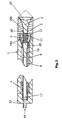
- Fig. 1 shown handpiece 1 consists of a housing 4 which receives a pneumatic inner cylinder 6 , in which a striking member 10 by means of pneumatic drive means 14 in conjunction with a dynamic pressure chamber 8, which surrounds the inner cylinder 6 coaxially annular, between two end positions is moved back and forth.
- a suitable length of the acceleration path can be selected.
- the acceleration travel is approx. 50 to 200 mm.
- the impact member 10 may be selected for the characterization of the pressure or shock wave in its length, final velocity and material composition.
- a power adjustment of the medical instrument is usually carried out by regulating the compressed air by means of a pressure reducer.
- a magnet holder 17 is arranged at the end of the inner cylinder 6 , which can hold the metallic impact member 10 in its proximal end position to again a pneumatic pressure applied via the terminal 13 , the impact member 10 toward the distal end of the inner cylinder 6 accelerates.
- the air located in the direction of movement of the percussion part 10 is conducted via an annular slot 16 located at the distal end of the inner cylinder 6 into the dynamic pressure chamber 8 .
- a transmission element 2 arranged distally from the inner cylinder 6 at a high end speed of, for example, 10 to 25 m / s and induces therein a pressure or shock wave which propagates to its exit boundary surface 19 and then coupled into the biological tissue.
- the transmission element 2 consists of a metallic material and is slidably guided in a receptacle 18 .
- An annular groove 3 is arranged in the transmission element 2 and in the receptacle 18 , in which an elastic spring / damping element 15 is located.
- the exit boundary surface 19 of the transmission element 2 is formed as part of a spherical surface.
- the focus 7 of the exiting pressure or shock wave corresponds in a first approximation to the geometric center of the spherical surface.
- the spring / damping element 15 moves the transmission element 2 back to its original position.
- the impact member 10 is returned by the pressure built-up in the dynamic pressure chamber 8 by the backflow of air through the annular slots 16 in its rest position at the proximal end of the inner cylinder 6 and fixed by the magnet holder 17 .
- the instrument is now ready to strike again.
- Fig. 2 embodiment shown additionally has an intermediate piece 9 with a seal 11 which is arranged between impact member 10 and transmission element 2 .
- This component has the task of being hit by the impact part 10 and forwarding the impact pulse to the transmission element 2 .
- the receptacle 18a and 18b is here constructed in two parts. By releasing the rotary joint 12, the transmitting member 2 and the front receptacle can be removed 18a.
- the handpiece 1 remains closed and can be easily cleaned, disinfected and sterilized without liquid or dirt could penetrate into the interior of the handpiece 1 .
- a transmission element 2 which has a large radius of curvature, whereby the focus 7 comes to lie further behind the exit boundary surface 19 .
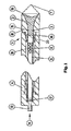
- Fig. 4 shows an embodiment with a small radius of curvature.
- the spherical exit boundary surface 19 of the transmission element 2 in Fig. 6 lined with an acoustically good conductive insert 5 , which has similar impedances as the biological tissue
Landscapes
- Health & Medical Sciences (AREA)
- Life Sciences & Earth Sciences (AREA)
- Veterinary Medicine (AREA)
- Public Health (AREA)
- General Health & Medical Sciences (AREA)
- Engineering & Computer Science (AREA)
- Animal Behavior & Ethology (AREA)
- Nuclear Medicine, Radiotherapy & Molecular Imaging (AREA)
- Surgery (AREA)
- Biomedical Technology (AREA)
- Orthopedic Medicine & Surgery (AREA)
- Molecular Biology (AREA)
- Medical Informatics (AREA)
- Vascular Medicine (AREA)
- Heart & Thoracic Surgery (AREA)
- Mechanical Engineering (AREA)
- Epidemiology (AREA)
- Pain & Pain Management (AREA)
- Physical Education & Sports Medicine (AREA)
- Rehabilitation Therapy (AREA)
- Radiology & Medical Imaging (AREA)
- Surgical Instruments (AREA)
- Materials For Medical Uses (AREA)
Description
- Die Erfindung betrifft ein medizinisches Instrument zur Behandlung von biologischem Gewebe nach dem Oberbegriff des Anspruchs 1.
- Derartige Instrumente dienen dazu, mittels Druck- oder Stoßwellen den Heilungsprozeß bei Knochenbrüchen und Knochendefekten, aber auch bei der Parodontose zu beschleunigen oder überhaupt erst in Gang zu bringen. Weitere Einsatzgebiete sind die Behandlung von chronischen Schmerzen bei Sehnenansatzerkrankungen und die Auflösung von myofaszialen Trigger-Arealen. Es wird vermutet, daß mit Hilfe der Druckwellen Mikroschädigungen im biologischen Gewebe erzeugt werden, die den Körper zu Regenerationsmaßnahmen veranlassen.
- Für solche Anwendungen werden bislang sogenannte extrakorporale Druck- oder Stoßwellengeräte benutzt. Diese Geräte erzeugen einen akustischen Impuls und leiten ihn über die Hautoberfläche auf das Zielgebiet innerhalb des Körpers weiter, wo er seine Wirkung dann entfaltet. Ein einfach aufgebautes Gerät dieser Geräteklasse ist in der Patentschrift
DE-A-197 25 477 beschrieben. Hier wird der akustische Impuls durch den Aufschlag eines Projektils erzeugt und unfokussiert über ein stumpfes Übertragungselement in den Körper eingekoppelt. Andere solcher medizinischen Geräte fokussieren den akustischen Impuls auf das Zielgebiet. Ein typisches Beispiel für ein solches Gerät ist in der Deutschen OffenlegungsschriftDE-A-23 51 247 zu finden. Hier dient eine Funkenentladung als Quelle für den akustischen Impuls, welcher durch einen ellipsoidförmigen Reflektor fokussiert wird. Zur Generierung der Druckwellen gehören mittlerweile auch elektromagnetische und piezoelektrische Quellen (DE-a-35 02 751 ) zum Stand der Technik. Bekannte alternative Mittel zur Fokussierung sind der Einsatz akustische Flüssigkeits- oder Feststofflinsen (US-A-5 727 875 ), die Ausbildung der akustischen Quelle als bewegte Kugelkalottenfläche (DE-C-33 12 014 ) oder auch die Anordnung mehrerer Quellen auf einer Kugeloberfläche (DE-A-199 28 491 ), wie sie bei piezoelektrischen Antrieben häufig zum Einsatz kommen. - Zum Betrieb aller bekannten fokussierenden Systemen ist ein Hochspannungsnetzteil notwendig, um die kurzen, aber heftigen, akustischen Impulse zu generieren. Dies macht die Geräte aufwendig, limitiert die maximale Wiederholfrequenz pro Zeiteinheit bei noch sinnvoller Baugröße und erfordert Sicherheitsmaßnahmen zur Isolierung der Hochspannung. Mit Ausführungsformen gemäß der
DE-A-197 25 477 ist eine Fokussierung der akustischen Energie nicht möglich und Anwendungen demnach auf oberflächennahe Indikationen beschränkt. - Aus der
US 2001/0014780 ist ein medizinisches Instrument bekannt, das mit Hilfe eines Ultraschallwandlers, der eine nach innen gewölbte konkave Austrittsgrenzfläche aufweist, eine fokussierte Druckwelle über ein Impedanzanpassungsmittel eingekoppelt. Die Erzeugung und Fokussierung der Druckwellen erfolgt dabei nicht an der Austrittsgrenzfläche des Impedanzanpassungsmittels. - Aus der
US-A-5 160 336 ist ein ballistischer Druckwellengenerator bekannt, wie er auch grundsätzlich aus derDE-A-197 25 477 bekannt ist. - Aus der
US-A-4 315 514 ist ein Verfahren zum selektiven Zerstören von Zellen bekannt, bei dem Ultraschallwellen mit einer Resonanzfrequenz der zu zerstörenden Zellen betrieben werden und mit Hilfe einer aus Polystyren gebildeten Linse auf die zu zerstörenden Zellen fokussiert werden. - Der Erfindung liegt demzufolge die Aufgabe zugrunde, ein Druck- oder Stoßwellengerät so auszubilden, daß es auf einfache und kostengünstige Weise Druck- oder Stoßwellen erzeugt und diese auf ein Zielgebiet im Körper fokussiert. Zur Lösung dieser Aufgabe dienen die Merkmale des Anspruchs 1.
- Die Erfindung besteht in vorteilhafter Weise aus einem primären Druckwellengenerator, bei dem ein Schlagteil mit Hilfe eines Antriebsmittels auf eine hohe Endgeschwindigkeit beschleunigbar ist und auf ein Übertragungselement einen Kraftstoß ausübt. Infolge dieses Kraftstoßes induziert das Schlagteil eine Druckwelle in dem Übertragungselement, welche sich in diesem in Richtung seiner Austrittsgrenzfläche fortpflanzt, um von dort in das biologische Gewebe eingekoppelt zu werden. Die Austrittsgrenzfläche ist dabei so beschaffen, daß die austretende Welle in dem biologischen Gewebe einen Fokus bildet. Dies wird durch eine Formgebung des Übertragungselementes erreicht, bei der für jede lokale Einzelwelle die Laufzeit von der Erzeugung beim Kraftstoß bis zum Fokus gleich ist. Die Eintrittsgrenzfläche des Übertragungselementes ist dabei kleiner als die Austrittsgrenzfläche. In erster Näherung würde sich für ein gerades Übertragungselement aus Stahl eine nahezu kugelförmige Austrittsgrenzfläche ergeben. Die Austrittsgrenzfläche hat einen größeren Durchmesser als die Eintrittsgrenzfläche oder die Querabmessung des Schlagteils.
- Das Übertragungselement ist als Exponentialtrichter ausgebildet, welcher die ebene Welle verlustfrei von kleinen auf größere Querschnitte überführt.
- Als Schlagteil ist vorzugsweise ein aus Metall oder einem anderen hochfesten Material bestehendes Projektil vorgesehen, welches in einer Führung mittels eines Druckluftpulses hin- und herbewegbar ist. Der pneumatische Antrieb eignet sich aufgrund seiner Einfachheit und des Gewichtsvorteils besonders gut, um das Schlagteil auf eine hohe Endgeschwindigkeit und damit verbundenen hohen Impulsenergien zu beschleunigen. Aber auch andere Antriebe durch einen Federmechanismus oder auf elektromagnetische Weise sind denkbar.
- Insbesondere bei orthopädischen Anwendungen ist es vorteilhaft, eine Vielzahl von einzelnen Impulsen in das biologische Gewebe einzukoppeln, um eine optimale Wirkung zu erzielen. Das Antriebsmittel ist daher vorzugsweise so ausgestaltet, daß eine periodische Hin- und Herbewegung des Schlagteils möglich ist. Die Schlagzahl beträgt ca. 1 bis 30 Hz, vorzugsweise 5 bis 12 Hz. Bei einer für orthopädische Anwendungen zur Zeit empfohlenen Impulszahl von ca. 2000 pro Sitzung sind damit Behandlungszeiten von unter fünf Minuten möglich.
- In einer bevorzugten Ausführungsform ist das Übertragungselement axial und linear in einem Gehäuse geführt, wobei ein Feder-/Dämpfungselement zwischen dem Übertragungselement und dem Gehäuse angeordnet ist. Auf diese Weise wird eine Entkopplung des Übertragungselementes realisiert. Außerdem ist eine große Auslenkung des Übertragungselementes nicht notwendig und auch nicht gewünscht, da diese von den Patienten als besonders schmerzhaft empfunden wird. Vielmehr erfolgt die Wellenübertragung durch eine Kompression bzw. Expansion des Übertragungselementes und nicht durch seine Verlagerung. Typische Werte für den Hub des Übertragungselementes liegen daher auch bei weniger als 0,5 mm.
- Zwischen dem Schlagteil und dem Übertragungselement kann ein Zwischenelement angeordnet sein, daß den Kraftstoß von dem Schlagteil auf das Übertragungselement weiterleitet. Diese Zwischenstück kann dazu dienen, eine bessere Abschirmung der Antriebsmittel gegenüber dem Applikationsbereich zu schaffen oder auch zum Umlenken der Richtung der Druckwelle oder aber zum Beeinflussen der Druckwellencharakteristik.
- Das Übertragungselement besteht vorzugsweise aus einem hochfesten Material, wie z.B. Stahl, um der Belastung durch das einwirkende Schlagteil Stand zu halten. In einer bevorzugten Ausführungsform sind die schlagende Fläche des Schlagteils und die getroffene Oberfläche des Übertragungselementes eben und senkrecht zur Bewegungsrichtung des Schlagteils. In einem solchen Fall entsteht durch den Aufschlag eine ebene Welle in dem Übertragungselement, welche sich in diesem fortpflanzt. Besteht das Übertragungselement aus einem Bolzen ohne wesentliche Querschnittsänderung, so behält die Welle ihre Form bei und wandert als ebene Welle in Richtung ihrer Austrittsgrenzfläche. Die bevorzugte Austrittsgrenzfläche des Übertragungselementes hat nahezu die Form einer nach innen gewölbten Kugeloberfläche. In einem solchen Fall gibt es einen Punkt in dem biologischen Gewebe, in welchem alle einzelnen lokalen Wellen - bedingt durch die unterschiedlichen Schallgeschwindigkeiten im Übertragungselement und im biologischen Gewebe - zur gleichen Zeit eintreffen und damit einen Fokus bilden. Die Position des Fokus im biologischen Gewebe relativ zum Übertragungselement kann durch die Auswahl des Krümmungsradiuses der Austrittsgrenzfläche voreingestellt werden. Die ideale Geometrie der Austrittsgrenzfläche weicht etwas von einer Kugeloberfläche ab und kann rechnerisch bestimmt werden.
- Zur Steigerung der abgestrahlten akustischen Leistung des Übertragungselementes ist seine Austrittsgrenzfläche möglichst groß zu wählen, der Durchmesser des Schlagteils aber möglichst klein zu halten, um die bewegten Massen und Impulse für eine medizinische Anwendung handhabbar zu gestalten. Es hat sich gezeigt, daß bei gleichem Durchmesser von Schlagteil und dem Austrittsbereich des Übertragungselementes eine Fokussierung nur bedingt möglich ist.
- Für eine optimale Erzeugung der Druckwelle im Übertragungselement sind die schlagende Fläche des Schlagteils und die Eintrittsfläche des Übertragungselementes gleich groß zu wählen. Der Austrittsdurchmesser des Übertragungselementes ist größer als die Querabmessung des Schlagteils, bzw. sein eigener Eintrittsdurchmesser zu bemaßen.
- Unter Vernachlässigung der idealen Weiterleitung sind auch beliebige andere Querschnittserweiterung des Übertragungselementes von seinem Eintritts- hin zum Austrittsdurchmesser denkbar. Die Geometrie der Austrittsgrenzfläche des Übertragungselementes ist dann wiederum so zu wählen, daß die Laufzeiten der Welle einen Fokus im biologischen Gewebe bilden.
- Bei solchen Übertragungselementen stehen die äußeren Kanten vor, welche durch die nach innen gewölbte Austrittsgrenzfläche gebildeten werden. Da durch den Aufschlagimpuls eine Bewegung des Übertragungselementes nicht vollständig vermieden werden kann, können diese vorstehenden Kanten das biologische Gewebe schädigen oder zumindest reizen. Daher sind bei einer bevorzugten Ausführungsform diese äußeren Kanten atraumatisch ausgebildet. Ein Abrunden der Kanten oder ein schützender Überzug sind geeignete Maßnahmen. Ebenso ist es vorstellbar, daß die äußeren Kanten des Gehäuses leicht in axiale Richtung überstehen, so daß das Übertragungselement nicht in direkten Kontakt mit dem biologischen Gewebe kommt.
- Zwischen der Austrittsgrenzfläche des Übertragungselementes und der Einkoppelstelle auf dem biologischen Gewebe kann ein Impedanzanpassungsmedium angeordnet sein, das die Einkopplung der Druckwelle in das biologische Gewebe verbessert. Befinden sich zwischen der Austrittsgrenzfläche des Übertragungselementes und der Eintrittsfläche des biologischen Gewebes Lufteinschlüsse, so wird ein Teil des Druckimpulses an dieser akustischen Unstetigkeit reflektiert und der übertragene Anteil gemindert. Ein geeignetes pastenförmiges Impedanzanpassungsmedium ist beispielsweise ein Ultraschallgel oder andere pastenfömige Massen mit einer ähnlichen Impedanz wie das biologische Gewebe (z.B. Vaseline).
- Zur Vermeidung von Lufteinschlüssen kann auch der durch die Kugelfläche gebildete Hohlraum mit einem festen, akustisch gut leitendem Material ausgekleidet sein. Ein solches geeignetes Material ist z.B. Polystyrol.
- Es zeigen:
-
Fig. 1 und2 Darstellungen eines mechanisch betriebenen medizinischen Instruments im Querschnitt, und -
Fig. 3 bis 6 eine Reihe von verschiedenen Ausbildungen eines Übertragungselementes. - Das in
Fig. 1 gezeigte Handstück 1 besteht aus einem Gehäuse 4, das einen pneumatischen Innenzylinder 6 aufnimmt, in dem ein Schlagteil 10 mit Hilfe pneumatischer Antriebsmittel 14 in Verbindung mit einer Staudruckkammer 8, die den Innenzylinder 6 koaxial ringförmig umgibt, zwischen zwei Endpositionen hin und her bewegt wird. Alternativ ist es auch möglich das Schlagteil 10 hydraulisch, mechanisch, elektromagnetisch oder durch andere Antriebsmittel zu bewegen. Je nach Antriebsart kann eine geeignete Länge des Beschleunigungswegs ausgewählt werden. Bei einem pneumatisch betriebenen Schlagwerk und einem gebräuchlichen Pressluftdruck von ca. 0,3 MPa (3 bar) beträgt der Beschleunigungsweg etwa 50 bis 200 mm. Das Schlagteil 10 kann zwecks Charakterisierung der Druck- oder Stoßwelle in seiner Länge, Endgeschwindigkeit und Materialzusammensetzung ausgewählt werden. Eine Leistungseinstellung des medizinischen Instrumentes erfolgt üblicherweise durch eine Regulierung der Druckluft mittels eines Druckminderers. - In der proximalen Endposition des Schlagteils 10 ist am Ende des Innenzylinders 6 ein Magnethalter 17 angeordnet, der das metallische Schlagteil 10 in seiner proximalen Endposition festhalten kann bis erneut ein über den Anschluß 13 aufgebrachter pneumatischer Druck das Schlagteil 10 in Richtung auf das distale Ende des Innenzylinders 6 beschleunigt. Die sich in Bewegungsrichtung des Schlagteils 10 befindliche Luft wird über an einen an dem distalen Ende des Innenzylinders 6 befindlichen Ringschlitze 16 in die Staudruckkammer 8 geleitet. Durch die Beschleunigung des Schlagteils 10 trifft dieses mit hoher Endgeschwindigkeit von beispielsweise 10 bis 25 m/s auf die distal von dem Innenzylinder 6 angeordnete Eintrittsgrenzfläche 20 eines Übertragungselementes 2 und induziert in diesem eine Druck- oder Stoßwelle, die sich bis zu seiner Austrittsgrenzfläche 19 fortpflanzt und dann in das biologische Gewebe eingekoppelt wird. Das Übertragungselement 2 besteht aus einem metallischen Material und ist in einer Aufnahme 18 gleitend geführt. Eine Ringnut 3 ist im Übertragungselement 2 und in der Aufnahme 18 angeordnet, in welcher sich ein elastisches Feder-/Dämpfungselement 15 befindet. Dieses hat die Aufgabe das Übertragungselement 2 von der Aufnahme 18 zu entkoppeln, sorgt aber auch dafür, daß das Übertragungselement 2 nach dem Schlagvorgang wieder in seine initiale Position zurückkehrt. Gleichzeitig dichtet das Feder-/Dämpfungselement 15 die Druckkammer 8 gegen den Außenraum ab und verhindert damit ein Austreten der Druckluft und das Eindringen von Schmutz. Die Austrittsgrenzfläche 19 des Übertragungselementes 2 ist als Teil einer Kugeloberfläche ausgebildet. Der Fokus 7 der austretenden Druck- oder Stoßwelle entspricht in erster Näherung dem geometrischen Mittelpunkt der Kugeloberfläche.
- Nach Beendigung des Schlagvorgangs bewegt das Feder-/Dämpfungselement 15 das Übertragungselement 2 wieder in seine Ausgangsposition zurück. Das Schlagteil 10 wird durch den in der Staudruckkammer 8 aufgebauten Überdruck durch das Zurückströmen der Luft durch die Ringschlitze 16 in seine Ruheposition am proximalen Ende des Innenzylinders 6 zurückgeführt und von dem Magnethalter 17 fixiert. Das Instrument ist nun wieder zu einem erneuten Schlagvorgang bereit.
- Die in
Fig. 2 dargestellte Ausführungsform besitzt zusätzlich ein Zwischenstück 9 mit einer Abdichtung 11, welches zwischen Schlagteil 10 und Übertragungselement 2 angeordnet ist. Dieses Bauteil hat die Aufgabe von dem Schlagteil 10 getroffen zu werden und den Schlagimpuls auf das Übertragungselement 2 weiterzuleiten. Die Aufnahme 18a und 18b ist hier zweiteilig aufgebaut. Durch Lösen der Drehverbindung 12 kann das Übertragungselement 2 und die vordere Aufnahme 18a entfernt werden. Das Handstück 1 bleibt dabei geschlossen und kann einfach gereinigt, desinfiziert und sterilisiert werden, ohne daß Flüssigkeit oder Schmutz in das Innere des Handstückes 1 eindringen könnte. - Durch Variation des Krümmungsradius der Austrittsgrenzfläche 19 des Übertragungselementes 2 kann die Position des Fokus 7 eingestellt werden. In
Fig. 3 ist ein Übertragungselement 2 gezeigt, welches einen großen Krümmungsradius aufweist, wodurch der Fokus 7 weiter hinter der Austrittsgrenzfläche 19 zu liegen kommt.Fig. 4 zeigt eine Ausführungsform mit einem kleinen Krümmungsradius. - Bedingt durch die geometrische Form der Austrittsgrenzfläche 19 des Übertragungselementes 2 bilden sich scharfe Kanten, die zu einer Verletzung oder Reizung des biologischen Gewebes führen können. Aus diesem Grund sind die äußeren Kanten des Übertragungselementes 2 in
Fig. 5 abgerundet. - Um Lufteinschlüsse zu vermeiden und eine ebenen Oberfläche des Übertragungselementes 2 zu erhalten, ist die kugelförmige Austrittsgrenzfläche 19 des Übertragungselementes 2 in
Fig. 6 mit einem akustisch gut leitendem Einsatz 5 ausgekleidet, welches ähnliche Impedanzen wie das biologische Gewebe besitzt
Claims (10)
- Medizinisches Instrument zur Behandlung von biologischem Gewebe, mit einer Einrichtung zum Erzeugen von extrakorporalen Druckwellen mit einer nach innen gewölbten Austrittsgrenzfläche (19) für Druckwellen, welche derart ausgebildet ist, dass die Druckwellen in das biologische Gewebe einkoppelbar sind und in dem biologischen Gewebe fokussierbar sind,
worin die Einrichtung zum Erzeugen von extrakorporalen Druckwellen ein Übertragungselement (2) zum Einkoppeln der Druckwellen in den Körper von Lebewesen aufweist,
worin die Austrittsgrenzfläche (19) an dem Übertragungselement (2) ausgebildet ist,
worin sich die Druckwellen in dem Übertragungselement (2) bis zur Austrittsgrenzfläche (19) fortpflanzen und durch das Übertragungselement (2) an der Austrittsgrenzfläche (19) fokussierbar sind,
dadurch gekennzeichnet,
dass die Druckwellen durch das Auftreffen eines Schlagteils (10) auf eine Eintrittsgrenzfläche (20) des Übertragungselementes (2) erzeugbar sind,
dass das Übertragungselement an der Austrittsgrenzfläche (19) einen größeren Durchmesser aufweist als an der Eintrittsgrenzfläche (20) oder als die Querabmessung des Schlagteils (10), und
dass das Übertragungselement (2) die Form eines Exponentialtrichters aufweist. - Medizinisches Instrument nach Anspruch 1, dadurch gekennzeichnet, dass die Einrichtung zum Erzeugen der Druckwellen aus einem in einem Gehäuse geführten mit Hilfe eines Antriebsmittels hin- und herbewegbaren Schlagteil (10) besteht, das auf das Übertragungselement (2) einen oder mehrere Kraftstöße ausübt, wobei das Schlagteil (10) infolge des Kraftstoßes eine Druckwelle in dem Übertragungselement (2) induziert, die sich bis zu der Austrittsgrenzfläche (19) des Übertragungselementes (2) fortpflanzt.
- Medizinisches Instrument nach Anspruch 2, dadurch gekennzeichnet, dass das Schlagteil (10) koaxial zu dem Übertragungselement (2) angeordnet ist.
- Medizinisches Instrument nach einem der Ansprüche 1 bis 3, dadurch gekennzeichnet, dass die Druckwellenquelle periodisch antreibbar ist, wobei das Schlagteil (10) und das Übertragungselement (2) selbsttätig rückstellbar sind.
- Medizinisches Instrument nach einem der Ansprüche 1 bis 4, dadurch gekennzeichnet, dass die Schlagfrequenz des Schlagteils (10) ca. 1 bis 30 Hz, vorzugsweise 1 bis 12 Hz beträgt.
- Medizinisches Instrument nach einem der Ansprüche 1 bis 5, dadurch gekennzeichnet, dass zwischen Übertragungselement (2) und dem Gehäuse (4) ein Feder-/Dämpfungselement (15) angeordnet ist.
- Medizinisches Instrument nach einem der Ansprüche 1 bis 6, dadurch gekennzeichnet, dass die Austrittsgrenzfläche (19) des Übertragung selementes (2) aufgrund des Kraftstoßes einen Hub von weniger als 0,5 mm ausführt.
- Medizinisches Instrument nach einem der Ansprüche 1 bis 7, dadurch gekennzeichnet, dass zwischen dem Schlagteil (10) und dem Übertragungselement (2) ein Zwischenelement (9) angeordnet ist, das den Kraftstoß von dem Schlagteil (10) auf das Übertragungselement (2) weiterleitet.
- Medizinisches Instrument nach einem der Ansprüche 1 bis 8, dadurch gekennzeichnet, dass die Außenkanten der Austrittsgrenzfläche des Übertragungselementes abgerundet sind oder mit einem schützenden Überzug versehen sind.
- Medizinisches Instrument nach einem der Ansprüche 1 bis 9, dadurch gekennzeichnet, dass zwischen der Austrittsgrenzfläche (19) des Übertragungselementes (2) und dem biologischen Gewebe impedanzanpassende Medien (5) angeordnet sind, die das Einkoppeln der Druckwelle in das biologische Gewebe verbessern.
Applications Claiming Priority (3)
| Application Number | Priority Date | Filing Date | Title |
|---|---|---|---|
| DE10215416.3A DE10215416B4 (de) | 2002-04-08 | 2002-04-08 | Medizinisches Gerät zur Behandlung von biologischem Gewebe |
| DE10215416 | 2002-04-08 | ||
| PCT/EP2003/003373 WO2003084608A1 (de) | 2002-04-08 | 2003-04-01 | Medizinisches gerät zur behandlung von biologischem gewebe |
Publications (3)
| Publication Number | Publication Date |
|---|---|
| EP1492594A1 EP1492594A1 (de) | 2005-01-05 |
| EP1492594B1 EP1492594B1 (de) | 2010-06-02 |
| EP1492594B2 true EP1492594B2 (de) | 2015-03-04 |
Family
ID=28051203
Family Applications (1)
| Application Number | Title | Priority Date | Filing Date |
|---|---|---|---|
| EP03717256.6A Expired - Lifetime EP1492594B2 (de) | 2002-04-08 | 2003-04-01 | Medizinisches gerät zur behandlung von biologischem gewebe |
Country Status (5)
| Country | Link |
|---|---|
| US (1) | US8034004B2 (de) |
| EP (1) | EP1492594B2 (de) |
| AT (1) | ATE469673T1 (de) |
| DE (2) | DE10215416B4 (de) |
| WO (1) | WO2003084608A1 (de) |
Families Citing this family (12)
| Publication number | Priority date | Publication date | Assignee | Title |
|---|---|---|---|---|
| ATE367787T1 (de) * | 2004-03-10 | 2007-08-15 | Elettronica Pagani S R L | Instrument zur medizinischen behandlung von gewebe mittels schockwellen |
| US20050245791A1 (en) * | 2004-04-30 | 2005-11-03 | Wolfgang Bauermeister | Shockwave method and apparatus for the application on the body |
| DE202007007921U1 (de) * | 2007-05-31 | 2008-10-09 | Storz Medical Ag | Medizinisches Gerät zur Behandlung des menschlichen oder tierischen Körpers mit Druck- oder Stoßwellen |
| ES2394197T3 (es) * | 2008-10-31 | 2013-01-23 | Ferton Holding Sa | Instrumento para generar ondas de presión a modo de ondas de choque para el tratamiento de tejido biológico |
| US9681923B2 (en) * | 2009-09-15 | 2017-06-20 | Koninklijke Philips N.V. | Medical ultrasound device with force detection |
| DE102009052132A1 (de) * | 2009-11-05 | 2011-05-12 | Uniphy Elektromedizin Gmbh & Co. Kg | Medizinische Vorrichtung zum Behandeln von biologischem Gewebe |
| WO2013082352A1 (en) * | 2011-12-01 | 2013-06-06 | Microbrightfield, Inc. | Acoustic pressure wave/shock wave mediated processing of biological tissue, and systems, apparatuses, and methods therefor |
| US11484724B2 (en) | 2015-09-30 | 2022-11-01 | Btl Medical Solutions A.S. | Methods and devices for tissue treatment using mechanical stimulation and electromagnetic field |
| US12220380B2 (en) | 2015-09-30 | 2025-02-11 | Btl Medical Solutions A.S. | Methods and devices for tissue treatment using mechanical stimulation and electromagnetic field |
| GB201617255D0 (en) | 2016-10-11 | 2016-11-23 | Oxford University Innovation Limited | Modular ultrasound apparatus and methods |
| EP3388003B1 (de) * | 2017-04-12 | 2020-07-22 | Storz Medical Ag | Druckwellengerät |
| CN108042334A (zh) * | 2017-12-18 | 2018-05-18 | 广东美的安川服务机器人有限公司 | 液压式冲击波治疗仪 |
Citations (4)
| Publication number | Priority date | Publication date | Assignee | Title |
|---|---|---|---|---|
| US3499437A (en) † | 1967-03-10 | 1970-03-10 | Ultrasonic Systems | Method and apparatus for treatment of organic structures and systems thereof with ultrasonic energy |
| DE3506583A1 (de) † | 1985-02-25 | 1986-08-28 | Siemens AG, 1000 Berlin und 8000 München | Stosswellengenerator mit frei beweglicher platte |
| DE3814743C2 (de) † | 1988-04-30 | 1994-01-27 | Wolf Gmbh Richard | Einrichtung zur Auflösung von Konkrementen in einer Körperhöhle |
| DE19929112A1 (de) † | 1999-06-24 | 2001-01-11 | Ferton Holding Sa | Medizinisches Instrument zur Behandlung von biologischem Gewebe sowie Verfahren zum Übertragen von Druckwellen |
Family Cites Families (31)
| Publication number | Priority date | Publication date | Assignee | Title |
|---|---|---|---|---|
| FR455868A (fr) | 1912-06-03 | 1913-08-11 | Jules Eugene Malivert | Avertisseur mécanique |
| US4095667A (en) * | 1977-01-19 | 1978-06-20 | Joseph Mahig | Portable underwater signalling transducer |
| DE3048293A1 (de) * | 1979-12-29 | 1981-10-15 | Mabuchi Motor Co.,Ltd., Tokyo | "schoenheitsbehandlungsvorrichtung" |
| US4315514A (en) * | 1980-05-08 | 1982-02-16 | William Drewes | Method and apparatus for selective cell destruction |
| BR8107560A (pt) * | 1981-11-19 | 1983-07-05 | Luiz Romariz Duarte | Estimulacao ultra-sonica da consolidacao de fraturas osseas |
| US4549535A (en) * | 1982-12-06 | 1985-10-29 | Wing Thomas W | Linear motor massage apparatus |
| DE3312014C2 (de) | 1983-04-02 | 1985-11-07 | Wolfgang Prof. Dr. 7140 Ludwigsburg Eisenmenger | Einrichtung zur berührungsfreien Zertrümmerung von Konkrementen im Körper von Lebewesen |
| DE3328051A1 (de) * | 1983-08-03 | 1985-02-14 | Siemens AG, 1000 Berlin und 8000 München | Einrichtung zum beruehrungslosen zertruemmern von konkrementen |
| JPS6163193A (ja) * | 1984-09-04 | 1986-04-01 | Nippon Chemicon Corp | 電気音響変換器 |
| DE3447440A1 (de) * | 1984-12-27 | 1986-07-03 | Siemens AG, 1000 Berlin und 8000 München | Stosswellenrohr fuer die zertruemmerung von konkrementen |
| DE3502751A1 (de) | 1985-01-28 | 1986-07-31 | Siemens AG, 1000 Berlin und 8000 München | Stosswellenrohr mit einer langen lebensdauer |
| FR2584148B1 (fr) * | 1985-06-28 | 1989-05-05 | Dory Jacques | Generateur d'impulsions elastiques de grande puissance focalisees dans un liquide et obtenues par percussion |
| DE3665949D1 (en) * | 1985-08-09 | 1989-11-02 | Siemens Ag | Ultrasonic generator |
| US4716890A (en) * | 1986-01-29 | 1988-01-05 | Bichel Ronald A | Chiropractic thruster |
| US4748971A (en) * | 1987-01-30 | 1988-06-07 | German Borodulin | Vibrational apparatus for accelerating passage of stones from ureter |
| DE8710118U1 (de) * | 1987-07-23 | 1988-11-17 | Siemens AG, 1000 Berlin und 8000 München | Stoßwellengenerator für eine Einrichtung zum berührungslosen Zertrümmern von Konkrementen im Körper eines Lebewesens |
| ES2030897T3 (es) * | 1987-11-18 | 1992-11-16 | Ferton Holding | Dispositivo para actuar sobre un objeto mediante vibraciones ultrasonicas. |
| US5529572A (en) * | 1992-01-24 | 1996-06-25 | Medispec Ltd. | Method and apparatus particularly useful for treating osteoporosis |
| DE4447855B4 (de) * | 1993-02-10 | 2008-10-16 | Siemens Ag | Verwendung einer Quelle impulsartiger Wellen, und zwar zur Behandlung von Schmerzzuständen und Gerät für eine solche Verwendung |
| DE4313768C2 (de) * | 1993-04-27 | 2002-07-11 | Walz Elektronik Gmbh | Vorrichtung zur Steinzertrümmerung |
| DE4315282C2 (de) * | 1993-05-07 | 1999-10-07 | Siemens Ag | Verwendung einer akustischen Druckimpulsquelle |
| US5618275A (en) * | 1995-10-27 | 1997-04-08 | Sonex International Corporation | Ultrasonic method and apparatus for cosmetic and dermatological applications |
| DE19618972C2 (de) * | 1996-05-10 | 2000-06-15 | Ferton Holding Delemont | Handgerät zur Verwendung bei der Lithotripsie |
| US5727875A (en) | 1996-12-05 | 1998-03-17 | Huang; Ming-Kun | Dual-functional lamp |
| DE19718511C5 (de) * | 1997-05-02 | 2010-10-21 | Sanuwave, Inc., | Gerät zur Applikation von akustischen Stoßwellen |
| DE19725477C2 (de) * | 1997-06-17 | 1999-10-21 | Ferton Holding | Medizinisches Instrument zur Behandlung von biologischem Gewebe |
| US6312434B1 (en) * | 1999-04-14 | 2001-11-06 | Northgate Technologies, Inc. | Device for producing a shock wave to impact an object |
| US6217530B1 (en) * | 1999-05-14 | 2001-04-17 | University Of Washington | Ultrasonic applicator for medical applications |
| DE19928491A1 (de) | 1999-06-22 | 2001-01-04 | Wolf Gmbh Richard | Vorrichtung, insbesondere Therapievorrichtung, zum Beschallen von Objekten mit fokussiertem Schall |
| US20030199857A1 (en) * | 2002-04-17 | 2003-10-23 | Dornier Medtech Systems Gmbh | Apparatus and method for manipulating acoustic pulses |
| US6875220B2 (en) * | 2002-12-30 | 2005-04-05 | Cybersonics, Inc. | Dual probe |
-
2002
- 2002-04-08 DE DE10215416.3A patent/DE10215416B4/de not_active Expired - Fee Related
-
2003
- 2003-04-01 AT AT03717256T patent/ATE469673T1/de active
- 2003-04-01 EP EP03717256.6A patent/EP1492594B2/de not_active Expired - Lifetime
- 2003-04-01 DE DE50312767T patent/DE50312767D1/de not_active Expired - Lifetime
- 2003-04-01 WO PCT/EP2003/003373 patent/WO2003084608A1/de not_active Ceased
- 2003-04-01 US US10/510,492 patent/US8034004B2/en not_active Expired - Fee Related
Patent Citations (4)
| Publication number | Priority date | Publication date | Assignee | Title |
|---|---|---|---|---|
| US3499437A (en) † | 1967-03-10 | 1970-03-10 | Ultrasonic Systems | Method and apparatus for treatment of organic structures and systems thereof with ultrasonic energy |
| DE3506583A1 (de) † | 1985-02-25 | 1986-08-28 | Siemens AG, 1000 Berlin und 8000 München | Stosswellengenerator mit frei beweglicher platte |
| DE3814743C2 (de) † | 1988-04-30 | 1994-01-27 | Wolf Gmbh Richard | Einrichtung zur Auflösung von Konkrementen in einer Körperhöhle |
| DE19929112A1 (de) † | 1999-06-24 | 2001-01-11 | Ferton Holding Sa | Medizinisches Instrument zur Behandlung von biologischem Gewebe sowie Verfahren zum Übertragen von Druckwellen |
Non-Patent Citations (4)
| Title |
|---|
| "Extrakorporale Stimulation des Herzens durch Druckpulse", DORNIER MEDIZINETECHNIK † |
| DR. OTHMAR WESS, ET AL.: "Externe Herzstimulation durch Druckpulse", DORNIER POST, 1 January 1981 (1981-01-01) † |
| FRANK S. CRAWFORD, JR.: "Schwingungen und Wellen", BERKELEY PHYSIK KURS 3, vol. 1982, pages 106 - 107 † |
| L.D. ROZENBERG: "Transmission of ultrasonic vibrations into media to be processed", ULTRASONIC TECHNOLOGY, vol. 2, 22 May 1969 (1969-05-22), NEW-YORK, pages 3 - 58 † |
Also Published As
| Publication number | Publication date |
|---|---|
| EP1492594A1 (de) | 2005-01-05 |
| DE50312767D1 (de) | 2010-07-15 |
| ATE469673T1 (de) | 2010-06-15 |
| DE10215416A1 (de) | 2003-10-16 |
| EP1492594B1 (de) | 2010-06-02 |
| US20050209586A1 (en) | 2005-09-22 |
| DE10215416B4 (de) | 2020-10-29 |
| US8034004B2 (en) | 2011-10-11 |
| WO2003084608A1 (de) | 2003-10-16 |
Similar Documents
| Publication | Publication Date | Title |
|---|---|---|
| EP0991447B1 (de) | Medizinisches instrument zur behandlung von biologischem gewebe | |
| EP1187563B1 (de) | Medizinisches instrument zur behandlung von biologischem gewebe sowie verfahren zum übertragen von druckwellen | |
| EP2529792B1 (de) | Instrument zur Behandlung von biologischem Gewebe mittels stoßwellenartiger Druckwellen | |
| EP2344252B1 (de) | Vorrichtung zum einleiten von stosswellen in einen lebenden körper und deren verwendung | |
| EP2157921B1 (de) | MEDIZINISCHES GERÄT ZUR BEHANDLUNG DES MENSCHLICHEN ODER TIERISCHEN KÖRPERS MIT DRUCK- ODER STOßWELLEN | |
| EP1492594B2 (de) | Medizinisches gerät zur behandlung von biologischem gewebe | |
| EP1643919B1 (de) | Vorrichtung zum fragmentieren von substanzen | |
| DE102020134602B4 (de) | Lithotripsievorrichtung, Lithotripsiesystem und Verfahren zum Betreiben einer Lithotripsievorrichtung | |
| DE102007013288B4 (de) | Vorrichtung zur Behandlung biologischer Körpersubstanzen mit mechanischen Druckwellen | |
| EP4039202B1 (de) | Vorrichtung zur erzeugung von stosswellen, insbesondere zur erzeugung eines komprimierten stosswellenwirkfeldes | |
| DE102009042276A1 (de) | Vorrichtung zum Einleiten von Stosswellen in einen lebenden Körper und deren Verwendung | |
| WO2008061645A1 (de) | Medizinisches gerät zur behandlung des menschlichen oder tierischen körpers mit mechanischem druck- oder stosswellen | |
| EP1574198B1 (de) | Instrument zur medizinischen Behandlung von Gewebe mittels Schockwellen | |
| EP1502626B1 (de) | Medizinisches Instrument zur Behandlung von biologischem Gewebe | |
| DE102022126984B4 (de) | Lithotripsievorrichtung zum Zertrümmern von Körpersteinen mit einem Gegenprojektil und Verfahren zum Beschleunigen eines Projektils einer Lithotripsievorrichtung | |
| EP2289435A1 (de) | Druckwellengerät zur Behandlung des menschlichen oder tierischen Körpers mit Piezolagenstapel | |
| DE20023753U1 (de) | Medizinisches Instrument zur Behandlung von biologischem Gewebe |
Legal Events
| Date | Code | Title | Description |
|---|---|---|---|
| PUAI | Public reference made under article 153(3) epc to a published international application that has entered the european phase |
Free format text: ORIGINAL CODE: 0009012 |
|
| 17P | Request for examination filed |
Effective date: 20040922 |
|
| AK | Designated contracting states |
Kind code of ref document: A1 Designated state(s): AT BE BG CH CY CZ DE DK EE ES FI FR GB GR HU IE IT LI LU MC NL PT RO SE SI SK TR |
|
| 17Q | First examination report despatched |
Effective date: 20050217 |
|
| 17Q | First examination report despatched |
Effective date: 20050217 |
|
| GRAP | Despatch of communication of intention to grant a patent |
Free format text: ORIGINAL CODE: EPIDOSNIGR1 |
|
| GRAS | Grant fee paid |
Free format text: ORIGINAL CODE: EPIDOSNIGR3 |
|
| 19A | Proceedings stayed before grant |
Effective date: 20080819 |
|
| 19A | Proceedings stayed before grant |
Effective date: 20080819 |
|
| 19F | Resumption of proceedings before grant (after stay of proceedings) |
Effective date: 20090302 |
|
| APAF | Appeal reference modified |
Free format text: ORIGINAL CODE: EPIDOSCREFNE |
|
| APBK | Appeal reference recorded |
Free format text: ORIGINAL CODE: EPIDOSNREFNE |
|
| APAF | Appeal reference modified |
Free format text: ORIGINAL CODE: EPIDOSCREFNE |
|
| APAF | Appeal reference modified |
Free format text: ORIGINAL CODE: EPIDOSCREFNE |
|
| APAV | Appeal reference deleted |
Free format text: ORIGINAL CODE: EPIDOSDREFNE |
|
| GRAA | (expected) grant |
Free format text: ORIGINAL CODE: 0009210 |
|
| AK | Designated contracting states |
Kind code of ref document: B1 Designated state(s): AT BE BG CH CY CZ DE DK EE ES FI FR GB GR HU IE IT LI LU MC NL PT RO SE SI SK TR |
|
| REG | Reference to a national code |
Ref country code: GB Ref legal event code: FG4D Free format text: NOT ENGLISH |
|
| REG | Reference to a national code |
Ref country code: CH Ref legal event code: EP |
|
| REG | Reference to a national code |
Ref country code: IE Ref legal event code: FG4D Free format text: LANGUAGE OF EP DOCUMENT: GERMAN |
|
| REF | Corresponds to: |
Ref document number: 50312767 Country of ref document: DE Date of ref document: 20100715 Kind code of ref document: P |
|
| REG | Reference to a national code |
Ref country code: CH Ref legal event code: NV Representative=s name: ISLER & PEDRAZZINI AG |
|
| RAP2 | Party data changed (patent owner data changed or rights of a patent transferred) |
Owner name: FERTON HOLDING SA |
|
| REG | Reference to a national code |
Ref country code: NL Ref legal event code: VDEP Effective date: 20100602 |
|
| PG25 | Lapsed in a contracting state [announced via postgrant information from national office to epo] |
Ref country code: SE Free format text: LAPSE BECAUSE OF FAILURE TO SUBMIT A TRANSLATION OF THE DESCRIPTION OR TO PAY THE FEE WITHIN THE PRESCRIBED TIME-LIMIT Effective date: 20100602 |
|
| PG25 | Lapsed in a contracting state [announced via postgrant information from national office to epo] |
Ref country code: SI Free format text: LAPSE BECAUSE OF FAILURE TO SUBMIT A TRANSLATION OF THE DESCRIPTION OR TO PAY THE FEE WITHIN THE PRESCRIBED TIME-LIMIT Effective date: 20100602 Ref country code: FI Free format text: LAPSE BECAUSE OF FAILURE TO SUBMIT A TRANSLATION OF THE DESCRIPTION OR TO PAY THE FEE WITHIN THE PRESCRIBED TIME-LIMIT Effective date: 20100602 |
|
| PG25 | Lapsed in a contracting state [announced via postgrant information from national office to epo] |
Ref country code: GR Free format text: LAPSE BECAUSE OF FAILURE TO SUBMIT A TRANSLATION OF THE DESCRIPTION OR TO PAY THE FEE WITHIN THE PRESCRIBED TIME-LIMIT Effective date: 20100903 Ref country code: CY Free format text: LAPSE BECAUSE OF FAILURE TO SUBMIT A TRANSLATION OF THE DESCRIPTION OR TO PAY THE FEE WITHIN THE PRESCRIBED TIME-LIMIT Effective date: 20100602 |
|
| REG | Reference to a national code |
Ref country code: IE Ref legal event code: FD4D |
|
| PG25 | Lapsed in a contracting state [announced via postgrant information from national office to epo] |
Ref country code: NL Free format text: LAPSE BECAUSE OF FAILURE TO SUBMIT A TRANSLATION OF THE DESCRIPTION OR TO PAY THE FEE WITHIN THE PRESCRIBED TIME-LIMIT Effective date: 20100602 Ref country code: EE Free format text: LAPSE BECAUSE OF FAILURE TO SUBMIT A TRANSLATION OF THE DESCRIPTION OR TO PAY THE FEE WITHIN THE PRESCRIBED TIME-LIMIT Effective date: 20100602 Ref country code: IE Free format text: LAPSE BECAUSE OF FAILURE TO SUBMIT A TRANSLATION OF THE DESCRIPTION OR TO PAY THE FEE WITHIN THE PRESCRIBED TIME-LIMIT Effective date: 20100602 |
|
| PG25 | Lapsed in a contracting state [announced via postgrant information from national office to epo] |
Ref country code: RO Free format text: LAPSE BECAUSE OF FAILURE TO SUBMIT A TRANSLATION OF THE DESCRIPTION OR TO PAY THE FEE WITHIN THE PRESCRIBED TIME-LIMIT Effective date: 20100602 Ref country code: PT Free format text: LAPSE BECAUSE OF FAILURE TO SUBMIT A TRANSLATION OF THE DESCRIPTION OR TO PAY THE FEE WITHIN THE PRESCRIBED TIME-LIMIT Effective date: 20101004 Ref country code: SK Free format text: LAPSE BECAUSE OF FAILURE TO SUBMIT A TRANSLATION OF THE DESCRIPTION OR TO PAY THE FEE WITHIN THE PRESCRIBED TIME-LIMIT Effective date: 20100602 |
|
| PLBI | Opposition filed |
Free format text: ORIGINAL CODE: 0009260 |
|
| PG25 | Lapsed in a contracting state [announced via postgrant information from national office to epo] |
Ref country code: IT Free format text: LAPSE BECAUSE OF FAILURE TO SUBMIT A TRANSLATION OF THE DESCRIPTION OR TO PAY THE FEE WITHIN THE PRESCRIBED TIME-LIMIT Effective date: 20100602 |
|
| 26 | Opposition filed |
Opponent name: STORZ MEDICAL AG Effective date: 20110302 |
|
| PLAX | Notice of opposition and request to file observation + time limit sent |
Free format text: ORIGINAL CODE: EPIDOSNOBS2 |
|
| PG25 | Lapsed in a contracting state [announced via postgrant information from national office to epo] |
Ref country code: DK Free format text: LAPSE BECAUSE OF FAILURE TO SUBMIT A TRANSLATION OF THE DESCRIPTION OR TO PAY THE FEE WITHIN THE PRESCRIBED TIME-LIMIT Effective date: 20100602 |
|
| REG | Reference to a national code |
Ref country code: DE Ref legal event code: R026 Ref document number: 50312767 Country of ref document: DE Effective date: 20110302 |
|
| PGFP | Annual fee paid to national office [announced via postgrant information from national office to epo] |
Ref country code: CZ Payment date: 20110323 Year of fee payment: 9 |
|
| PLBB | Reply of patent proprietor to notice(s) of opposition received |
Free format text: ORIGINAL CODE: EPIDOSNOBS3 |
|
| BERE | Be: lapsed |
Owner name: FERTON HOLDING SA Effective date: 20110430 |
|
| PG25 | Lapsed in a contracting state [announced via postgrant information from national office to epo] |
Ref country code: MC Free format text: LAPSE BECAUSE OF NON-PAYMENT OF DUE FEES Effective date: 20110430 |
|
| GBPC | Gb: european patent ceased through non-payment of renewal fee |
Effective date: 20110401 |
|
| PG25 | Lapsed in a contracting state [announced via postgrant information from national office to epo] |
Ref country code: BE Free format text: LAPSE BECAUSE OF NON-PAYMENT OF DUE FEES Effective date: 20110430 |
|
| PG25 | Lapsed in a contracting state [announced via postgrant information from national office to epo] |
Ref country code: GB Free format text: LAPSE BECAUSE OF NON-PAYMENT OF DUE FEES Effective date: 20110401 |
|
| PGFP | Annual fee paid to national office [announced via postgrant information from national office to epo] |
Ref country code: FR Payment date: 20120511 Year of fee payment: 10 |
|
| REG | Reference to a national code |
Ref country code: AT Ref legal event code: MM01 Ref document number: 469673 Country of ref document: AT Kind code of ref document: T Effective date: 20110401 |
|
| PG25 | Lapsed in a contracting state [announced via postgrant information from national office to epo] |
Ref country code: AT Free format text: LAPSE BECAUSE OF NON-PAYMENT OF DUE FEES Effective date: 20110401 |
|
| PLAY | Examination report in opposition despatched + time limit |
Free format text: ORIGINAL CODE: EPIDOSNORE2 |
|
| PLBC | Reply to examination report in opposition received |
Free format text: ORIGINAL CODE: EPIDOSNORE3 |
|
| PG25 | Lapsed in a contracting state [announced via postgrant information from national office to epo] |
Ref country code: LU Free format text: LAPSE BECAUSE OF NON-PAYMENT OF DUE FEES Effective date: 20110401 |
|
| PLAY | Examination report in opposition despatched + time limit |
Free format text: ORIGINAL CODE: EPIDOSNORE2 |
|
| PLBC | Reply to examination report in opposition received |
Free format text: ORIGINAL CODE: EPIDOSNORE3 |
|
| PG25 | Lapsed in a contracting state [announced via postgrant information from national office to epo] |
Ref country code: BG Free format text: LAPSE BECAUSE OF FAILURE TO SUBMIT A TRANSLATION OF THE DESCRIPTION OR TO PAY THE FEE WITHIN THE PRESCRIBED TIME-LIMIT Effective date: 20100902 Ref country code: TR Free format text: LAPSE BECAUSE OF FAILURE TO SUBMIT A TRANSLATION OF THE DESCRIPTION OR TO PAY THE FEE WITHIN THE PRESCRIBED TIME-LIMIT Effective date: 20100602 |
|
| PG25 | Lapsed in a contracting state [announced via postgrant information from national office to epo] |
Ref country code: ES Free format text: LAPSE BECAUSE OF FAILURE TO SUBMIT A TRANSLATION OF THE DESCRIPTION OR TO PAY THE FEE WITHIN THE PRESCRIBED TIME-LIMIT Effective date: 20100913 Ref country code: CZ Free format text: LAPSE BECAUSE OF NON-PAYMENT OF DUE FEES Effective date: 20130401 Ref country code: HU Free format text: LAPSE BECAUSE OF FAILURE TO SUBMIT A TRANSLATION OF THE DESCRIPTION OR TO PAY THE FEE WITHIN THE PRESCRIBED TIME-LIMIT Effective date: 20100602 |
|
| APBM | Appeal reference recorded |
Free format text: ORIGINAL CODE: EPIDOSNREFNO |
|
| APBP | Date of receipt of notice of appeal recorded |
Free format text: ORIGINAL CODE: EPIDOSNNOA2O |
|
| APAH | Appeal reference modified |
Free format text: ORIGINAL CODE: EPIDOSCREFNO |
|
| REG | Reference to a national code |
Ref country code: FR Ref legal event code: ST Effective date: 20131231 |
|
| PG25 | Lapsed in a contracting state [announced via postgrant information from national office to epo] |
Ref country code: FR Free format text: LAPSE BECAUSE OF NON-PAYMENT OF DUE FEES Effective date: 20130430 |
|
| APBU | Appeal procedure closed |
Free format text: ORIGINAL CODE: EPIDOSNNOA9O |
|
| PUAH | Patent maintained in amended form |
Free format text: ORIGINAL CODE: 0009272 |
|
| STAA | Information on the status of an ep patent application or granted ep patent |
Free format text: STATUS: PATENT MAINTAINED AS AMENDED |
|
| 27A | Patent maintained in amended form |
Effective date: 20150304 |
|
| AK | Designated contracting states |
Kind code of ref document: B2 Designated state(s): AT BE BG CH CY CZ DE DK EE ES FI FR GB GR HU IE IT LI LU MC NL PT RO SE SI SK TR |
|
| REG | Reference to a national code |
Ref country code: DE Ref legal event code: R102 Ref document number: 50312767 Country of ref document: DE |
|
| REG | Reference to a national code |
Ref country code: CH Ref legal event code: AELC |
|
| REG | Reference to a national code |
Ref country code: DE Ref legal event code: R102 Ref document number: 50312767 Country of ref document: DE Effective date: 20150304 |
|
| PGFP | Annual fee paid to national office [announced via postgrant information from national office to epo] |
Ref country code: CH Payment date: 20170425 Year of fee payment: 15 Ref country code: DE Payment date: 20170502 Year of fee payment: 15 |
|
| REG | Reference to a national code |
Ref country code: DE Ref legal event code: R119 Ref document number: 50312767 Country of ref document: DE |
|
| REG | Reference to a national code |
Ref country code: CH Ref legal event code: PL |
|
| PG25 | Lapsed in a contracting state [announced via postgrant information from national office to epo] |
Ref country code: DE Free format text: LAPSE BECAUSE OF NON-PAYMENT OF DUE FEES Effective date: 20181101 |
|
| PG25 | Lapsed in a contracting state [announced via postgrant information from national office to epo] |
Ref country code: CH Free format text: LAPSE BECAUSE OF NON-PAYMENT OF DUE FEES Effective date: 20180430 Ref country code: LI Free format text: LAPSE BECAUSE OF NON-PAYMENT OF DUE FEES Effective date: 20180430 |