EP3808216A1 - Möbelteilsteuerungsmodul - Google Patents
Möbelteilsteuerungsmodul Download PDFInfo
- Publication number
- EP3808216A1 EP3808216A1 EP20199764.0A EP20199764A EP3808216A1 EP 3808216 A1 EP3808216 A1 EP 3808216A1 EP 20199764 A EP20199764 A EP 20199764A EP 3808216 A1 EP3808216 A1 EP 3808216A1
- Authority
- EP
- European Patent Office
- Prior art keywords
- furniture part
- control module
- part control
- designed
- furniture
- Prior art date
- Legal status (The legal status is an assumption and is not a legal conclusion. Google has not performed a legal analysis and makes no representation as to the accuracy of the status listed.)
- Granted
Links
Images

Classifications
-
- A—HUMAN NECESSITIES
- A47—FURNITURE; DOMESTIC ARTICLES OR APPLIANCES; COFFEE MILLS; SPICE MILLS; SUCTION CLEANERS IN GENERAL
- A47B—TABLES; DESKS; OFFICE FURNITURE; CABINETS; DRAWERS; GENERAL DETAILS OF FURNITURE
- A47B88/00—Drawers for tables, cabinets or like furniture; Guides for drawers
- A47B88/40—Sliding drawers; Slides or guides therefor
- A47B88/453—Actuated drawers
- A47B88/457—Actuated drawers operated by electrically-powered actuation means
-
- A—HUMAN NECESSITIES
- A47—FURNITURE; DOMESTIC ARTICLES OR APPLIANCES; COFFEE MILLS; SPICE MILLS; SUCTION CLEANERS IN GENERAL
- A47B—TABLES; DESKS; OFFICE FURNITURE; CABINETS; DRAWERS; GENERAL DETAILS OF FURNITURE
- A47B2220/00—General furniture construction, e.g. fittings
- A47B2220/0091—Electronic or electric devices
- A47B2220/0097—Remote control for furniture, e.g. tables or shelves
-
- A—HUMAN NECESSITIES
- A47—FURNITURE; DOMESTIC ARTICLES OR APPLIANCES; COFFEE MILLS; SPICE MILLS; SUCTION CLEANERS IN GENERAL
- A47F—SPECIAL FURNITURE, FITTINGS, OR ACCESSORIES FOR SHOPS, STOREHOUSES, BARS, RESTAURANTS OR THE LIKE; PAYING COUNTERS
- A47F10/00—Furniture or installations specially adapted to particular types of service systems, not otherwise provided for
- A47F2010/005—Furniture or installations specially adapted to particular types of service systems, not otherwise provided for using RFID elements
Definitions
- Voice control for controlling lighting elements on a furniture body is known.
- a user can send a voice command to a receiving unit of the voice control, the receiving unit converting the voice command and controlling a control unit on the piece of furniture.
- the control unit in turn regulates a lighting element which is arranged on a furniture body on the basis of the control command from the receiving unit.
- the invention is based on the object of providing an alternative furniture part control module for controlling a movable furniture part of a piece of furniture.
- the invention is based on the object of providing an improved furniture part control module for controlling a movable furniture part of a piece of furniture, in which a coupling of a transmitting and receiving unit of the furniture part control module to an external control device is simplified.
- the invention is based on a furniture part control module for controlling a movable furniture part of a piece of furniture.
- the furniture part control module has a transmitting and receiving unit, the transmitting and receiving unit comprising a data interface, the data interface being designed to receive information from an external control device and information to the external control device
- the data interface is designed to receive or transmit the information wirelessly
- the furniture part control module having a control module, the control module controlling the movable furniture part on the basis of the information received from the control device via the data interface, the furniture part control module having an identification element has, by means of which the furniture part control module can be identified. This enables a comparatively simple coupling of the furniture part control module to the external control device.
- the furniture part control module is preferably designed to control lighting of a movable furniture part and / or a drive device of a movable furniture part.
- the furniture part control module is available, for example, as a drawer control module. It is also conceivable that the furniture part control module is designed as a furniture part lighting control module or as a drawer lighting control module.
- the data interface is designed, for example, as an electromagnetic transmit and receive interface, for example as an antenna.
- the data interface is, for example, a radio interface, for example a WLAN interface, a Bluetooth interface and / or an NFC interface.
- the identification member is advantageously present as an additional element, in particular as a separate element that is independent of other components of the furniture part control module, for example.
- the identification member is attached to a housing of the furniture part control module.
- the identification element is applied to a housing of the furniture part control module.
- the identification member is glued to a housing of the furniture part control module.
- a housing of the furniture part control module integrally contains the identification element.
- the identification member is let into a housing wall of a housing of the furniture part control module.
- the identification element is designed as an RFID element. As a result, it can be arranged on the furniture part control module in such a way that it is invisible to a user. It is conceivable that the RFID element is present as an RFID transponder. It is also conceivable that the identification element is designed as an NFC element, in particular as an NFC transmitting and / or receiving element.
- the identification element is present as a character or as a character element, the character or the character element being designed to be opto-electronically readable.
- the identification element in particular the character, is present as a barcode and / or as a two-dimensional barcode, e.g. as a QR code.
- the identification element is advantageously designed to be detectable by a camera and to be readable or evaluable by a detection unit.
- the identification element is designed as a three-dimensional character.
- the identification organ is present as a symbol or as a visual sign.
- the identification element is arranged on an outside of a housing, in particular on an outside of a housing wall of the housing, of the furniture part control module. In this way, it can advantageously be achieved for a particularly optical recognition system.
- the identification element is advantageously permanently present on the furniture part control module.
- the identification element is permanently connected to the housing of the furniture part control module.
- the identification element is advantageously arranged on the furniture part control module so that it can be seen by a viewer.
- the furniture part control module is designed to be arranged on a drive device for driving a movable furniture part, in particular in an exchangeable manner.
- the furniture part control module has a connecting element for connecting the furniture part control module to the drive device for driving the movable furniture part.
- the furniture part control module preferably has a connecting element for connecting the furniture part control module to a lighting unit of the movable furniture part, in particular to a lighting unit of a frame, in particular a side wall, of the movable furniture part.
- the furniture part control module can be detachably connected to the drive device and / or the lighting unit.
- An advantageous embodiment of the invention is a system comprising a furniture part control module according to one of the aforementioned variants and a control device, the control device being designed to read out information from the identification element or to receive information from the identification element, the system for this purpose is designed to compare the read or received information with a database in order to verify the authenticity of the furniture part control module and, if the furniture part control module is genuine, allow the furniture part control module to be integrated into the system. This makes it possible to ensure, in particular, improved reliability of a function of the system.
- the system is advantageously provided as a furniture system.
- control unit is designed to read out information from the identification element or to receive it from the identification element, the system being designed to verify the authenticity of the information read or received by checking the information for a defined pattern , for example by forming a checksum of the information, the system allowing the furniture part control module to be integrated into the system if the furniture part control module is authentic.
- the information is embodied, for example, as a serial number of the furniture part control module, as a password matched to the furniture part control module and / or as an identification number matched to the furniture part control module.
- the database advantageously includes information from various furniture part control modules, in particular information from various furniture part control modules of a single furniture part control module series, for example information from various furniture part control modules from a single manufacturer.
- the system preferably verifies the authenticity of the information read out when the information read out is contained in the database.
- control device of the system has a control unit and a data interface, the data interface being designed to receive data from the furniture part control module and to send data to the furniture part control module, the control unit has a memory module to store data, wherein the control device has an input unit to define a date by a user, which is to be sent to the furniture part control module.
- a date is a light color, a light intensity, a light brightness and / or an illumination duration.
- the database is preferably filed or stored in the memory module.
- the control device is designed to store or save a configuration of the furniture part control module, in particular a configuration of the drive device and / or a configuration of the lighting unit to which the furniture part control module can be connected, in the memory module.
- the information is advantageously a parameter of the configuration of the furniture part control module, in particular a parameter of the configuration of the drive device and / or a parameter of the configuration of the lighting unit. It is conceivable that the information is present as an in particular complete configuration of the furniture part control module, in particular a complete configuration of the drive device and / or in particular a complete configuration of the lighting unit.
- control device of the system is designed as a mobile device, in particular as a mobile phone or as a tablet.
- the control device preferably comprises a barcode scanner, a QR code scanner and / or an NFC scanner.
- the control device of the system is advantageously designed to connect to the database via an Internet data connection.
- a further advantageous embodiment of the invention is a drive device for driving a movable furniture part, the drive device comprising a furniture part control module according to one of the variants mentioned above, wherein the Furniture part control module is designed to regulate and / or control a drive unit of the drive device.
- the drive device is advantageously designed as a furniture drive device.
- An advantageous modification of the invention is a frame of a movable furniture part, in particular a frame of a drawer, with a furniture part control module according to one of the variants mentioned above or a drive device as mentioned above.
- the frame advantageously comprises a lighting unit.
- the lighting unit can preferably be regulated by the furniture part control module.
- a further advantageous modification of the invention is a piece of furniture, in particular a movable furniture part, e.g. a drawer, with a furniture part control module according to one of the variants mentioned above, with a drive device or with a frame as mentioned above.
- the movable furniture part in particular the drawer, advantageously comprises two opposing and spaced-apart side walls, in particular frames, a drawer front, a drawer rear wall and a drawer bottom.
- the five aforementioned elements of the movable furniture part preferably enclose a drawer interior.
- the movable furniture part is movably mounted on a furniture body of the furniture by means of a movement device.
- the furniture part control module is designed to be arranged on the movement device.
- the movement device is available as a drawer slide, e.g. as a pull-out, in particular as a full-length pull-out.
- the movable furniture part is advantageously relative to the furniture body by means of the drive unit of the drive device of the furniture movable, in particular drivable.
- the movable furniture part can be moved by means of the drive unit of the drive device from a closed state on the furniture body of the furniture to an open state on the furniture body of the furniture, or vice versa.
- FIG Figure 1 A furniture part control module 1 according to the invention is shown in FIG Figure 1 shown.
- the furniture part control module 1 comprises a transmitting and receiving unit 2, which has a data interface 3, and a control module 5.
- the transmitting and receiving unit 2 is formed within a housing 4 of the furniture part control module 1.
- the furniture part control module 1, in particular on the housing 4 comprises an identification element 6.
- the identification element 6 is advantageously attached to an outer side 7 of the housing 4.
- an external control device 8 which has a control unit 9, an input unit 16 and a data interface 11.
- the control unit 9 advantageously comprises a memory module 10.
- the control device 8 is designed, for example, as a mobile phone.
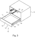
- FIG 3 a piece of furniture 12 comprising a furniture body 13 and a movable furniture part 14 in the form of a drawer is shown.
- the movable furniture part 14 is in Figure 3 shown in an open state relative to the furniture body 13 of the furniture 12.
- the movable furniture part 14 is movably supported on the furniture body 13 via a full extension 22.
- a furniture part control module 15 is arranged on the piece of furniture 12, for example.
- the movable furniture part 14 comprises two side walls 17 in the form of frames, a drawer rear wall 18, a drawer front 19 and a drawer bottom 20.
- a drive device 21 is preferably provided on the piece of furniture 12 in order to move the movable furniture part 14 from a closed state relative to the furniture body 13 into the position shown in FIG Figure 3 open state shown or vice versa.
Landscapes
- Selective Calling Equipment (AREA)
- Power-Operated Mechanisms For Wings (AREA)
Abstract
Description
- Eine Sprachsteuerung zur Steuerung von Beleuchtungselementen an einem Möbelkorpus ist bekannt. Mittels der bekannten Sprachsteuerung kann ein Nutzer einen Sprachbefehl an eine Empfangseinheit der Sprachsteuerung senden, wobei die Empfangseinheit den Sprachbefehl umwandelt und eine Kontrolleinheit am Möbel ansteuert. Die Kontrolleinheit wiederum regelt aufgrund des Steuerungsbefehls der Empfangseinheit ein Beleuchtungselement, welches an einem Möbelkorpus angeordnet ist.
- Bei der bekannten Sprachsteuerung ist eine Kopplung der Empfangseinheit und der Kontrolleinheit vergleichsweise aufwendig.
- Der Erfindung liegt die Aufgabe zugrunde ein alternatives Möbelteilsteuerungsmodul zum Steuern eines bewegbaren Möbelteils eines Möbels bereitzustellen. Insbesondere liegt der Erfindung die Aufgabe zugrunde ein verbessertes Möbelteilsteuerungsmodul zum Steuern eines bewegbaren Möbelteils eines Möbels bereitzustellen, bei welchem eine Kopplung einer Sende- und Empfangseinheit des Möbelteilsteuerungsmoduls mit einer externen Kontrolleinrichtung vereinfacht ist.
- Diese Aufgabe wird durch die Merkmale des Anspruchs 1 gelöst.
- In den abhängigen Ansprüchen sind vorteilhafte und zweckmäßige Ausführungsformen der Erfindung angegeben.
- Die Erfindung geht von einem Möbelteilsteuerungsmodul zum Steuern eines bewegbaren Möbelteils eines Möbels aus.
- Ein wesentlicher Aspekt der Erfindung ist darin zu sehen, dass das Möbelteilsteuerungsmodul eine Sende- und Empfangseinheit aufweist, wobei die Sende- und Empfangseinheit eine Datenschnittstelle umfasst, wobei die Datenschnittstelle dazu ausgebildet ist, Informationen von einer externen Kontrolleinrichtung zu empfangen und Informationen an die externe Kontrolleinrichtung zu senden, wobei die Datenschnittstelle dazu ausgebildet ist, die Informationen drahtlos zu empfangen oder zu übermitteln, wobei das Möbelteilsteuerungsmodul ein Kontrollmodul aufweist, wobei das Kontrollmodul auf Basis der über die Datenschnittstelle von der Kontrolleinrichtung empfangenen Informationen das bewegbare Möbelteil steuert, wobei das Möbelteilsteuerungsmodul ein Identifikationsorgan aufweist, mittels welchem das Möbelteilsteuerungsmodul identifizierbar ist. Hierdurch ist eine vergleichsweise einfache Kopplung des Möbelteilsteuerungsmoduls mit der externen Kontrolleinrichtung ermöglicht.
- Bevorzugterweise ist das Möbelteilsteuerungsmodul zum Steuern einer Beleuchtung eines bewegbaren Möbelteils und/oder einer Antriebsvorrichtung eines bewegbaren Möbelteils ausgebildet. Das Möbelteilsteuerungsmodul ist beispielsweise als ein Schubladensteuerungsmodul vorhanden. Denkbar ist auch, dass das Möbelteilsteuerungsmodul als ein Möbelteilbeleuchtungssteuerungsmodul oder als ein Schubladenbeleuchtungssteuerungsmodul ausgebildet ist.
- Die Datenschnittstelle ist beispielsweise als eine elektromagnetische Sende- und Empfangsschnittstelle ausgebildet, zum Beispiel als eine Antenne. Die Datenschnittstelle ist beispielsweise eine Funkschnittstelle, zum Beispiel eine WLAN-Schnittstelle, eine Bluetooth-Schnittstelle und/oder eine NFC-Schnittstelle.
- Vorteilhafterweise ist das Identifikationsorgan als ein zusätzliches, insbesondere als ein separates, beispielsweise von anderen Komponenten des Möbelteilsteuerungsmoduls unabhängiges Element vorhanden. Beispielsweise ist das Identifikationsorgan an einem Gehäuse des Möbelteilsteuerungsmoduls angebracht. Insbesondere ist das Identifikationsorgan auf ein Gehäuse des Möbelteilsteuerungsmoduls aufgebracht. Beispielsweise ist das Identifikationsorgan auf ein Gehäuse des Möbelteilsteuerungsmoduls aufgeklebt. Denkbar ist auch, dass ein Gehäuse des Möbelteilsteuerungsmoduls das Identifikationsorgan integral beinhaltet. Beispielsweise ist das Identifikationsorgan in eine Gehäusewand eines Gehäuses des Möbelteilsteuerungsmoduls eingelassen.
- Auch ist es von Vorteil, dass das Identifikationsorgan als ein RFID-Element ausgebildet ist. Hierdurch kann es für einen Nutzer unsichtbar am Möbelteilsteuerungsmodul angeordnet sein. Vorstellbar ist, dass das RFID-Element als ein RFID-Transponder vorhanden ist. Denkbar ist auch, dass das Identifikationsorgan als ein NFC-Element, insbesondere als ein NFC-Sende- und/oder Empfangselement ausgebildet ist.
- Weiter wird vorgeschlagen, dass das Identifikationsorgan als ein Zeichen oder als ein Zeichenelement vorhanden ist, wobei das Zeichen oder das Zeichenelement opto-elektronisch auslesbar ausgebildet ist. Beispielsweise ist das Identifikationsorgan, insbesondere das Zeichen als ein Barcode und/oder als ein zweidimensionaler Strichcode, z.B. als ein QR-Code, vorhanden. Vorteilhafterweise ist das Identifikationsorgan dazu ausgebildet, von einer Kamera erfassbar und von einer Erkennungseinheit auslesbar oder auswertbar zu sein.
- Denkbar ist auch, dass das Identifikationsorgan als ein dreidimensionales Zeichen ausgebildet ist. Beispielsweise ist das Identifikationsorgan als ein Symbol oder als ein visuelles Zeichen vorhanden.
- Außerdem ist es von Vorteil, dass das Identifikationsorgan an einer Außenseite eines Gehäuses, insbesondere an einer Außenseite einer Gehäusewand des Gehäuses, des Möbelteilsteuerungsmoduls angeordnet ist. Hierdurch ist es für ein insbesondere optisches Erkennungssystem vorteilhaft erreichbar.
- Vorteilhafterweise ist das Identifikationsorgan unlösbar am Möbelteilsteuerungsmodul vorhanden. Beispielsweise ist das Identifikationsorgan unlösbar mit dem Gehäuse des Möbelteilsteuerungsmoduls verbunden. Vorteilhafterweise ist das Identifikationsorgan am Möbelteilsteuerungsmodul für einen Betrachter sichtbar angeordnet.
- Von Vorteil erweist sich auch, dass das Möbelteilsteuerungsmodul ausgebildet ist, an eine Antriebsvorrichtung zum Antreiben eines bewegbaren Möbelteils, insbesondere auswechselbar, angeordnet zu werden. Beispielsweise besitzt das Möbelteilsteuerungsmodul ein Verbindungselement zum Verbinden des Möbelteilsteuerungsmoduls mit der Antriebsvorrichtung zum Antreiben des bewegbaren Möbelteils. Bevorzugterweise besitzt das Möbelteilsteuerungsmodul ein Verbindungsorgan zum Verbinden des Möbelteilsteuerungsmoduls mit einer Beleuchtungseinheit des bewegbaren Möbelteils, insbesondere mit einer Beleuchtungseinheit einer Zarge, insbesondere einer Seitenwand, des bewegbaren Möbelteils. Beispielsweise ist das Möbelteilsteuerungsmodul lösbar mit der Antriebsvorrichtung und/oder der Beleuchtungseinheit verbindbar.
- Eine vorteilhafte Ausführungsform der Erfindung ist ein System umfassen ein Möbelteilsteuerungsmodul nach einem der vorangegangenen genannten Varianten und eine Kontrolleinrichtung, wobei die Kontrolleinrichtung dazu ausgebildet ist, eine Information des Identifikationsorgans auszulesen oder vom Identifikationsorgan zu empfangen, wobei das System dazu ausgebildet ist, die ausgelesene oder empfangene Information mit einer Datenbank abzugleichen, um damit eine Echtheit des Möbelteilsteuerungsmoduls zu verifizieren und bei Echtheit des Möbelteilsteuerungsmoduls eine Einbindung des Möbelteilsteuerungsmoduls in das System zuzulassen. Hierdurch ist eine insbesondere verbesserte Zuverlässigkeit einer Funktion des Systems gewährleistbar. Das System ist vorteilhafterweise als ein Möbelsystem vorhanden.
- Vorstellbar ist auch, dass die Kontrolleinheit dazu ausgebildet ist, eine Information des Identifikationsorgan auszulesen oder vom Identifikationsorgan zu empfangen, wobei das System dazu ausgebildet ist, eine Echtheit der ausgelesenen oder empfangenen Information dadurch zu verifizieren, dass die Information auf ein definiertes Muster hin überprüft wird, beispielsweise indem eine Checksum der Information gebildet wird, wobei das System bei Echtheit des Möbelteilsteuerungsmoduls eine Einbindung des Möbelteilsteuerungsmoduls in das System zulässt.
- Die Information ist beispielsweise als eine Seriennummer des Möbelteilsteuerungsmoduls, als ein auf das Möbelteilsteuerungsmodul abgestimmtes Kennwort und/oder als eine auf das Möbelteilsteuerungsmodul abgestimmte Kennnummer ausgebildet. Vorteilhafterweise umfasst die Datenbank Informationen verschiedener Möbelteilsteuerungsmodule, insbesondere Informationen verschiedener Möbelteilsteuerungsmodule einer einzigen Möbelteilsteuerungsmodul-Serie, beispielsweise Informationen verschiedener Möbelteilsteuerungsmodule eines einzigen Herstellers. Bevorzugterweise verifiziert das System die Echtheit der ausgelesenen Information dann, wenn die ausgelesene Information in der Datenbank enthalten ist.
- Weiter wird vorgeschlagen, dass die Kontrolleinrichtung des Systems eine Kontrolleinheit und eine Datenschnittstelle aufweist, wobei die Datenschnittstelle dazu ausgebildet ist, Daten vom Möbelteilsteuerungsmodul zu empfangen und Daten an das Möbelteilsteuerungsmodul zu senden, wobei die Kontrolleinheit ein Speichermodul aufweist, um Daten zu speichern, wobei die Kontrolleinrichtung eine Eingabeeinheit aufweist, um ein Datum durch einen Benutzer festzulegen, welche an das Möbelteilsteuerungsmodul gesendet werden soll. Beispielsweise ist ein Datum eine Lichtfarbe, eine Lichtstärke, eine Lichthelligkeit und/oder eine Beleuchtungsdauer. Bevorzugterweise ist die Datenbank im Speichermodul abgelegt oder abgespeichert.
- Beispielsweise ist die Kontrolleinrichtung dazu ausgebildet, eine Konfiguration des Möbelteilsteuerungsmoduls, insbesondere eine Konfiguration der Antriebsvorrichtung und/oder eine Konfiguration der Beleuchtungseinheit mit welcher das Möbelteilsteuerungsmodul verbindbar ist, im Speichermodul abzulegen oder abzuspeichern. Vorteilhafterweise ist die Informationen ein Parameter der Konfiguration des Möbelteilsteuerungsmoduls, insbesondere ein Parameter der Konfiguration der Antriebsvorrichtung und/oder ein Parameter der Konfiguration der Beleuchtungseinheit. Vorstellbar ist, dass die Informationen als insbesondere vollständige Konfiguration des Möbelteilsteuerungsmoduls, insbesondere vollständige Konfiguration der Antriebsvorrichtung und/oder insbesondere vollständige Konfiguration der Beleuchtungseinheit vorhanden ist.
- Von Vorteil erweist sich auch, die Kontrolleinrichtung des Systems als ein Mobilgerät ausgebildet ist, insbesondere als ein Mobiltelefon oder als ein Tablet. Bevorzugterweise umfasst die Kontrolleinrichtung einen Barcodescanner, einen QR-Code-Scanner und/oder einen NFC-Scanner.
- Vorteilhafterweise ist die Kontrolleinrichtung des Systems dazu ausgebildet, über eine Internet-Datenverbindung mit der Datenbank in Verbindung zu treten.
- Eine weitere vorteilhafte Ausführungsform der Erfindung ist eine Antriebsvorrichtung zum Antreiben eines bewegbaren Möbelteils, wobei die Antriebsvorrichtung ein Möbelteilsteuerungsmodul nach einer der vorangegangen genannten Varianten umfasst, wobei das Möbelteilsteuerungsmodul ausgebildet ist, eine Antriebseinheit der Antriebsvorrichtung zu regeln und/oder zu kontrollieren. Vorteilhafterweise ist die Antriebsvorrichtung als eine Möbelantriebsvorrichtung ausgebildet.
- Eine vorteilhafte Modifikation der Erfindung ist eine Zarge eines bewegbaren Möbelteils, insbesondere eine Zarge einer Schublade, mit einem Möbelteilsteuerungsmodul nach einer der vorangegangen genannten Varianten oder einer Antriebsvorrichtung wie vorangegangen genannt.
- Vorteilhafterweise umfasst die Zarge eine Beleuchtungseinheit. Bevorzugterweise ist die Beleuchtungseinheit durch das Möbelteilsteuerungsmodul regelbar.
- Eine weitere vorteilhafte Modifikation der Erfindung ist ein Möbel, insbesondere ein bewegbares Möbelteil, z.B. eine Schublade, mit einem Möbelteilsteuerungsmodul nach einer der vorangegangen genannten Varianten, mit einer Antriebsvorrichtung oder mit einer Zarge wie vorangegangen genannt.
- Vorteilhafterweise umfasst das bewegbare Möbelteil, insbesondere die Schublade, zwei sich gegenüberliegende und voneinander beabstandete Seitenwände, insbesondere Zargen, eine Schubladenfront, eine Schubladenrückwand und ein Schubladenboden. Bevorzugterweise umschließen die fünf vorangegangen genannten Elemente des bewegbaren Möbelteils einen Schubladeninnenraum.
- Vorstellbar ist auch, dass das bewegbare Möbelteil mittels einer Bewegungsvorrichtung an einem Möbelkorpus des Möbels beweglich gelagert ist. Denkbar ist weiterhin, dass das Möbelteilsteuerungsmodul dazu ausgebildet ist, an der Bewegungsvorrichtung angeordnet zu werden. Beispielsweise ist die Bewegungsvorrichtung als eine Schubladenführung, z.B. als ein Auszug, insbesondere als ein Vollauszug, vorhanden.
- Vorteilhafterweise ist das bewegbare Möbelteil mittels der Antriebseinheit der Antriebsvorrichtung relativ zum Möbelkorpus des Möbels bewegbar, insbesondere antreibbar. Beispielsweise ist das bewegbare Möbelteil mittels der Antriebseinheit der Antriebsvorrichtung von einem geschlossenen Zustand am Möbelkorpus des Möbels in einen geöffneten Zustand am Möbelkorpus des Möbels bewegbar oder umgekehrt.
- Ein Ausführungsbeispiel wird anhand der nachstehenden schematischen Zeichnungen unter Angabe weitere Einzelheiten und Vorteile näher erläutert.
- Es zeigen:
- Figur 1
- ein erfindungsgemäßes Möbelteilsteuerungsmodul,
- Figur 2
- eine externe Kontrolleinrichtung und
- Figur 3
- in einer perspektivische Ansicht von seitlich vorne oben ein Möbel mit einem Möbelteilsteuerungsmodul.
- Ein erfindungsgemäßes Möbelteilsteuerungsmodul 1 ist in
Figur 1 gezeigt. Das Möbelteilsteuerungsmodul 1 umfasst eine Sende- und Empfangseinheit 2, welche eine Datenschnittstelle 3 aufweist und ein Kontrollmodul 5. Die Sende- und Empfangseinheit 2 ist innerhalb eines Gehäuses 4 des Möbelteilsteuerungsmoduls 1 ausgebildet. Außerdem umfasst das Möbelteilsteuerungsmodul 1, insbesondere am Gehäuse 4 ein Identifikationsorgan 6. Vorteilhafterweise ist das Identifikationsorgan 6 an einer Außenseite 7 des Gehäuses 4 befestigt. - In
Figur 2 ist eine externe Kontrolleinrichtung 8 gezeigt, welche eine Kontrolleinheit 9, eine Eingabeeinheit 16 und eine Datenschnittstelle 11 aufweist. Die Kontrolleinheit 9 umfasst vorteilhafterweise ein Speichermodul 10. Die Kontrolleinrichtung 8 ist beispielsweise als ein Mobiltelefon ausgebildet. - In
Figur 3 ist ein Möbel 12 umfassend einen Möbelkorpus 13 und ein bewegbares Möbelteil 14 in Form einer Schublade abgebildet. Das bewegbare Möbelteil 14 ist inFigur 3 in einem geöffneten Zustand relativ zum Möbelkorpus 13 des Möbels 12 gezeigt. Beispielsweise ist das bewegbare Möbelteil 14 über einen Vollauszug 22 beweglich am Möbelkorpus 13 gelagert. Am Möbel 12 ist beispielsweise ein Möbelteilsteuerungsmodul 15 angeordnet. - Das bewegbare Möbelteil 14 umfasst zwei Seitenwände 17 in Form von Zargen, eine Schubladenrückwand 18, eine Schubladenfront 19, sowie einen Schubladenboden 20.
- Bevorzugterweise ist am Möbel 12 eine Antriebsvorrichtung 21 vorhanden, um das bewegbare Möbelteil 14 aus einem geschlossenen Zustand relativ zum Möbelkorpus 13 in den in
Figur 3 gezeigten geöffneten Zustand zu bewegen oder umgekehrt. -
- 1
- Möbelteilsteuerungsmodul
- 2
- Sende- und Empfangseinheit
- 3
- Datenschnittstelle
- 4
- Gehäuse
- 5
- Kontrollmodul
- 6
- Identifikationsorgan
- 7
- Außenseite
- 8
- Kontrolleinrichtung
- 9
- Kontrolleinheit
- 10
- Speichermodul
- 11
- Datenschnittstelle
- 12
- Möbel
- 13
- Möbelkorpus
- 14
- bewegbares Möbelteil
- 15
- Möbelteilsteuerungsmodul
- 16
- Eingabeeinheit
- 17
- Seitenwand
- 18
- Schubladenrückwand
- 19
- Schubladenfront
- 20
- Schubladenboden
- 21
- Antriebsvorrichtung
- 22
- Vollauszug
Claims (11)
- Möbelteilsteuerungsmodul (1) zum Steuern eines bewegbaren Möbelteils (14) eines Möbels (12), wobei das Möbelteilsteuerungsmodul (1) eine Sende- und Empfangseinheit (2) aufweist, wobei die Sende- und Empfangseinheit (2) eine Datenschnittstelle (3) umfasst, wobei die Datenschnittstelle (3) dazu ausgebildet ist, Informationen von einer externen Kontrolleinrichtung (8) zu empfangen und Informationen an die externe Kontrolleinrichtung (8) zu senden, wobei die Datenschnittstelle (3) dazu ausgebildet ist, die Informationen drahtlos zu empfangen oder zu übermitteln, wobei das Möbelteilsteuerungsmodul (1) ein Kontrollmodul (5) aufweist, wobei das Kontrollmodul (5) auf Basis der über die Datenschnittstelle (3) von der Kontrolleinrichtung (8) empfangenen Informationen das bewegbare Möbelteil (14) steuert, wobei das Möbelteilsteuerungsmodul (1) ein Identifikationsorgan (6) aufweist, mittels welchem das Möbelteilsteuerungsmodul (1) identifizierbar ist.
- Möbelteilsteuerungsmodul (1) nach dem vorangegangenen Anspruch 1, dadurch gekennzeichnet, dass das Identifikationsorgan (6) als ein RFID-Element ausgebildet ist.
- Möbelteilsteuerungsmodul (1) nach einem der vorangegangenen Ansprüche, dadurch gekennzeichnet, dass das Identifikationsorgan (6) als ein Zeichen vorhanden ist, welches optoelektronisch auslesbar ausgebildet ist.
- Möbelteilsteuerungsmodul (1) nach einem der vorangegangenen Ansprüche, dadurch gekennzeichnet, dass das Identifikationsorgan (6) an einer Außenseite (7) eines Gehäuses (4) des Möbelteilsteuerungsmoduls (1) angeordnet ist.
- Möbelteilsteuerungsmodul (1) nach einem der vorangegangenen Ansprüche, dadurch gekennzeichnet, dass das Möbelteilsteuerungsmodul (1) ausgebildet ist, an eine Antriebsvorrichtung zum Antreiben eines bewegbaren Möbelteils (14), insbesondere auswechselbar, angeordnet zu werden.
- System umfassen ein Möbelteilsteuerungsmodul (1) nach einem der vorangegangenen Ansprüche und eine Kontrolleinrichtung (8), dadurch gekennzeichnet, dass die Kontrolleinrichtung (8) dazu ausgebildet ist, eine Information des Identifikationsorgans (6) auszulesen oder vom Identifikationsorgan (6) zu empfangen, wobei das System dazu ausgebildet ist, die ausgelesene oder empfangene Information mit einer Datenbank abzugleichen, um damit eine Echtheit des Möbelteilsteuerungsmoduls (1) zu verifizieren und bei Echtheit des Möbelteilsteuerungsmoduls (1) eine Einbindung des Möbelteilsteuerungsmoduls (1) in das System zuzulassen.
- System nach dem vorangegangenen Anspruch 6, dadurch gekennzeichnet, dass die Kontrolleinrichtung (8) eine Kontrolleinheit (9) und eine Datenschnittstelle (3) aufweist, wobei die Datenschnittstelle (3) dazu ausgebildet ist, Informationen vom Möbelteilsteuerungsmodul (1) zu empfangen und Informationen an das Möbelteilsteuerungsmodul (1) zu senden, wobei die Kontrolleinheit (9) ein Speichermodul (10) aufweist, um Informationen zu speichern, wobei die Kontrolleinrichtung (8) eine Eingabeeinheit (16) aufweist, um eine Information durch einen Benutzer festzulegen, welche an das Möbelteilsteuerungsmodul (1) gesendet werden soll.
- System nach einem der vorangegangenen Ansprüche 6 oder 7, dadurch gekennzeichnet, dass die Kontrolleinrichtung (8) als ein Mobilgerät ausgebildet ist, insbesondere als ein Mobiltelefon oder als ein Tablet.
- Antriebsvorrichtung (21) zum Antreiben eines bewegbaren Möbelteils (14), wobei die Antriebsvorrichtung (21) ein Möbelteilsteuerungsmodul (1) nach einem der vorangegangenen Ansprüche 1 bis 5 umfasst, wobei das Möbelteilsteuerungsmodul (1) ausgebildet ist, eine Antriebseinheit der Antriebsvorrichtung (21) zu regeln und/oder zu kontrollieren.
- Zarge (17) eines bewegbaren Möbelteils (14) mit einem Möbelteilsteuerungsmodul (1) nach einem der vorangegangenen Ansprüche 1 bis 5 oder einer Antriebsvorrichtung (21) nach dem vorangegangenen Anspruch 9.
- Möbel (12), insbesondere ein bewegbares Möbelteil (14), mit einem Möbelteilsteuerungsmodul (1) nach einem der vorangegangenen Ansprüche 1 bis 5 oder einer Antriebsvorrichtung (21) nach dem vorangegangenen Anspruch 9 oder mit einer Zarge (17) nach dem vorangegangenen Anspruch 10.
Applications Claiming Priority (1)
| Application Number | Priority Date | Filing Date | Title |
|---|---|---|---|
| DE202019105743.2U DE202019105743U1 (de) | 2019-10-17 | 2019-10-17 | Möbelteilsteuerungsmodul |
Publications (2)
| Publication Number | Publication Date |
|---|---|
| EP3808216A1 true EP3808216A1 (de) | 2021-04-21 |
| EP3808216B1 EP3808216B1 (de) | 2024-08-28 |
Family
ID=72744588
Family Applications (1)
| Application Number | Title | Priority Date | Filing Date |
|---|---|---|---|
| EP20199764.0A Active EP3808216B1 (de) | 2019-10-17 | 2020-10-02 | System umfassend ein möbelteilsteuerungsmodul und eine kontrolleinrichtung |
Country Status (2)
| Country | Link |
|---|---|
| EP (1) | EP3808216B1 (de) |
| DE (1) | DE202019105743U1 (de) |
Family Cites Families (8)
| Publication number | Priority date | Publication date | Assignee | Title |
|---|---|---|---|---|
| US10064784B2 (en) * | 2006-09-14 | 2018-09-04 | Martin B. Rawls-Meehan | System and method of an adjustable bed with a vibration motor |
| KR102274422B1 (ko) * | 2013-01-18 | 2021-07-07 | 가부시키가이샤 유야마 세이사쿠쇼 | 약품 불출 장치, 약품 불출 방법, 약품 불출 프로그램, 기록 매체 |
| WO2014143810A1 (en) * | 2013-03-15 | 2014-09-18 | Intermetro Industries Corporation | Medication storage and dispensing apparatus |
| WO2014179403A1 (en) * | 2013-04-30 | 2014-11-06 | Waterloo Industries, Inc. | Electronic storage device access systems and methods |
| EP3373883B1 (de) * | 2015-11-13 | 2022-01-05 | Humanscale Corporation | Medizinisch-technologische station und verfahren zur verwendung |
| WO2017196190A1 (en) * | 2016-05-12 | 2017-11-16 | Graham Mary Frances | A secure last mile delivery solution for items/parcels by drone, robot and courier |
| DE102017201443A1 (de) * | 2017-01-30 | 2018-08-02 | Fresenius Medical Care Deutschland Gmbh | Mobiles Auswahlsystem und Behandlungswagen |
| CN110324487A (zh) * | 2019-05-21 | 2019-10-11 | 站坐(宁波)智能科技有限公司 | 升降桌和升降桌控制系统 |
-
2019
- 2019-10-17 DE DE202019105743.2U patent/DE202019105743U1/de active Active
-
2020
- 2020-10-02 EP EP20199764.0A patent/EP3808216B1/de active Active
Non-Patent Citations (5)
| Title |
|---|
| FIRGELLI AUTOMATIONS: "How to Build a Pop Up Drawer in Your Wine Cellar That Provides Hidden Storage", 19 July 2019 (2019-07-19), https://www.firgelliauto.com, pages 1 - 6, XP055777730, Retrieved from the Internet <URL:https://www.firgelliauto.com/blogs/news/how-to-build-a-pop-up-drawer-in-your-wine-cellar-that-provides-hidden-storage?_pos=16&_sid=1ad477f38&_ss=r> [retrieved on 20210218] * |
| LEATHER EXPRESSIONS: "Introducing the NEW Trionfo Sofa with BLUETOOTH Capabilities", YOUTUBE, 5 June 2019 (2019-06-05), pages 1 pp., XP054981441, Retrieved from the Internet <URL:https://www.youtube.com/watch?v=d4vYoPkvA7w> [retrieved on 20210219] * |
| LINAK: "Desk Control(TM) App - How to connect a Bluetooth adapter to an app", YOUTUBE, 3 December 2018 (2018-12-03), pages 1 pp., XP054981443, Retrieved from the Internet <URL:https://www.youtube.com/watch?v=zugHj77KRIY> [retrieved on 20210218] * |
| PROGRESSIVE AUTOMATION: "WiFi linear actuator Controller Kit with dual channels for parallel control of electric actuators", 11 June 2014 (2014-06-11), www.amazon.com, pages 1 - 6, XP055777725, Retrieved from the Internet <URL:https://www.amazon.com/Progressive-Automations-WIFI-Actuator-Control/dp/B00KXFMW5I#descriptionAndDetails> [retrieved on 20210218] * |
| XIANG GAO: "How to Remote Control Linear Actuator Motor via Mobile Phone WiFi Controller", YOUTUBE, 1 July 2014 (2014-07-01), pages 1 pp., XP054981442, Retrieved from the Internet <URL:https://www.youtube.com/watch?v=KhmOlH0G_3E> [retrieved on 20210219] * |
Also Published As
| Publication number | Publication date |
|---|---|
| DE202019105743U1 (de) | 2021-01-20 |
| EP3808216B1 (de) | 2024-08-28 |
Similar Documents
| Publication | Publication Date | Title |
|---|---|---|
| DE69635110T2 (de) | Vorrichtung für das Ermitteln einer Richtung, in der ein Identifizierungsetikett durch ein Portal bewegt wird | |
| EP3596564B1 (de) | Biegeschritt-auswahlverfahren, ausgeführt auf einem steuerungssystem einer biegemaschine | |
| DE102011080456A1 (de) | Anordnung und Verfahren zur Unterstützung einer Herstellung einer Steckverbindung | |
| WO1999058794A1 (de) | Mobiler transponder für ein fahrzeug | |
| DE102005041862A1 (de) | Anordnung zum Bedienen eines Feldgeräts | |
| WO2015074763A1 (de) | Anordnung mit einem ventil und verfahren zum betreiben einer anordnung | |
| WO2002067205A1 (de) | Schlüssellose zugangsberechtigungskontrolleinrichtung sowie identifikationsgeber dafür | |
| EP3808216B1 (de) | System umfassend ein möbelteilsteuerungsmodul und eine kontrolleinrichtung | |
| DE10055534A1 (de) | Mikroskop | |
| DE102021124561A1 (de) | Verfahren zum Interagieren einer Person mit einem Fahrzeug | |
| DE102013104401A1 (de) | Verfahren zur Fertigung eines Ersatzteiles einer Schließvorrichtung | |
| EP4067003A1 (de) | Werkzeugsystem, antriebseinheit und werkzeugkopf | |
| EP3012698B1 (de) | System und verfahren zur drahtlosen konfiguration und/oder parametrierung von kleinsteuergeräten | |
| EP2780229A1 (de) | Sitzsteuerungsvorrichtung, insbesondere für einen fluggastsitz | |
| DE10334462A1 (de) | Sitz mit Datenspeicher, insbesondere Fluggastsitz, und zugehöriges Lesegerät | |
| DE102006057430A1 (de) | Verfahren und Vorrichtung zur Benutzeridentifikation in einem Fahrzeug | |
| DE102014003937A1 (de) | Verfahren zur bidirektionalen Kommunikation zwischen einem Kraftfahrzeug und einer Infrastruktureinrichtung und Kraftfahrzeug | |
| DE102014019441A1 (de) | Verfahren zum Montieren wenigstens eines Bauteils | |
| DE102023127580A1 (de) | Rettungszeichenleuchte mit überprüfung des dargestellten rettungswegbildes | |
| EP4553797A1 (de) | Zutrittskontrollsystem sowie verfahren zu einem betrieb des zutrittskontrollsystems | |
| DE102008009665B3 (de) | Möbel mit Datenübertragungsschnittstelle | |
| DE102010007236A1 (de) | Portabler Datenträger zum Anzeigen von Transaktionsdaten | |
| WO2026017496A1 (de) | Modul zur lösbaren befestigung an einer haltevorrichtung | |
| EP3293032A1 (de) | Handschalter für eine hubladebühne und verfahren zum bedienen einer hubladebühne | |
| WO2018010832A1 (de) | Vorrichtung und verfahren zum betrieb eines fahrzeugzugangs- und/oder fahrberechtigungssystems |
Legal Events
| Date | Code | Title | Description |
|---|---|---|---|
| PUAI | Public reference made under article 153(3) epc to a published international application that has entered the european phase |
Free format text: ORIGINAL CODE: 0009012 |
|
| STAA | Information on the status of an ep patent application or granted ep patent |
Free format text: STATUS: THE APPLICATION HAS BEEN PUBLISHED |
|
| AK | Designated contracting states |
Kind code of ref document: A1 Designated state(s): AL AT BE BG CH CY CZ DE DK EE ES FI FR GB GR HR HU IE IS IT LI LT LU LV MC MK MT NL NO PL PT RO RS SE SI SK SM TR |
|
| AX | Request for extension of the european patent |
Extension state: BA ME |
|
| STAA | Information on the status of an ep patent application or granted ep patent |
Free format text: STATUS: REQUEST FOR EXAMINATION WAS MADE |
|
| 17P | Request for examination filed |
Effective date: 20211001 |
|
| RBV | Designated contracting states (corrected) |
Designated state(s): AL AT BE BG CH CY CZ DE DK EE ES FI FR GB GR HR HU IE IS IT LI LT LU LV MC MK MT NL NO PL PT RO RS SE SI SK SM TR |
|
| STAA | Information on the status of an ep patent application or granted ep patent |
Free format text: STATUS: EXAMINATION IS IN PROGRESS |
|
| 17Q | First examination report despatched |
Effective date: 20230424 |
|
| GRAP | Despatch of communication of intention to grant a patent |
Free format text: ORIGINAL CODE: EPIDOSNIGR1 |
|
| STAA | Information on the status of an ep patent application or granted ep patent |
Free format text: STATUS: GRANT OF PATENT IS INTENDED |
|
| GRAJ | Information related to disapproval of communication of intention to grant by the applicant or resumption of examination proceedings by the epo deleted |
Free format text: ORIGINAL CODE: EPIDOSDIGR1 |
|
| STAA | Information on the status of an ep patent application or granted ep patent |
Free format text: STATUS: EXAMINATION IS IN PROGRESS |
|
| INTG | Intention to grant announced |
Effective date: 20240315 |
|
| RIC1 | Information provided on ipc code assigned before grant |
Ipc: A47F 10/00 20060101ALN20240304BHEP Ipc: A47C 31/00 20060101ALI20240304BHEP Ipc: A47B 88/457 20170101AFI20240304BHEP |
|
| GRAP | Despatch of communication of intention to grant a patent |
Free format text: ORIGINAL CODE: EPIDOSNIGR1 |
|
| STAA | Information on the status of an ep patent application or granted ep patent |
Free format text: STATUS: GRANT OF PATENT IS INTENDED |
|
| INTC | Intention to grant announced (deleted) | ||
| RIC1 | Information provided on ipc code assigned before grant |
Ipc: A47F 10/00 20060101ALN20240411BHEP Ipc: A47C 31/00 20060101ALI20240411BHEP Ipc: A47B 88/457 20170101AFI20240411BHEP |
|
| INTG | Intention to grant announced |
Effective date: 20240424 |
|
| GRAS | Grant fee paid |
Free format text: ORIGINAL CODE: EPIDOSNIGR3 |
|
| GRAA | (expected) grant |
Free format text: ORIGINAL CODE: 0009210 |
|
| STAA | Information on the status of an ep patent application or granted ep patent |
Free format text: STATUS: THE PATENT HAS BEEN GRANTED |
|
| AK | Designated contracting states |
Kind code of ref document: B1 Designated state(s): AL AT BE BG CH CY CZ DE DK EE ES FI FR GB GR HR HU IE IS IT LI LT LU LV MC MK MT NL NO PL PT RO RS SE SI SK SM TR |
|
| REG | Reference to a national code |
Ref country code: CH Ref legal event code: EP |
|
| REG | Reference to a national code |
Ref country code: DE Ref legal event code: R096 Ref document number: 502020009012 Country of ref document: DE |
|
| REG | Reference to a national code |
Ref country code: IE Ref legal event code: FG4D Free format text: LANGUAGE OF EP DOCUMENT: GERMAN |
|
| REG | Reference to a national code |
Ref country code: LT Ref legal event code: MG9D |
|
| PG25 | Lapsed in a contracting state [announced via postgrant information from national office to epo] |
Ref country code: NO Free format text: LAPSE BECAUSE OF FAILURE TO SUBMIT A TRANSLATION OF THE DESCRIPTION OR TO PAY THE FEE WITHIN THE PRESCRIBED TIME-LIMIT Effective date: 20241128 |
|
| PG25 | Lapsed in a contracting state [announced via postgrant information from national office to epo] |
Ref country code: NL Free format text: LAPSE BECAUSE OF FAILURE TO SUBMIT A TRANSLATION OF THE DESCRIPTION OR TO PAY THE FEE WITHIN THE PRESCRIBED TIME-LIMIT Effective date: 20240828 Ref country code: PT Free format text: LAPSE BECAUSE OF FAILURE TO SUBMIT A TRANSLATION OF THE DESCRIPTION OR TO PAY THE FEE WITHIN THE PRESCRIBED TIME-LIMIT Effective date: 20241230 Ref country code: FI Free format text: LAPSE BECAUSE OF FAILURE TO SUBMIT A TRANSLATION OF THE DESCRIPTION OR TO PAY THE FEE WITHIN THE PRESCRIBED TIME-LIMIT Effective date: 20240828 Ref country code: PL Free format text: LAPSE BECAUSE OF FAILURE TO SUBMIT A TRANSLATION OF THE DESCRIPTION OR TO PAY THE FEE WITHIN THE PRESCRIBED TIME-LIMIT Effective date: 20240828 Ref country code: GR Free format text: LAPSE BECAUSE OF FAILURE TO SUBMIT A TRANSLATION OF THE DESCRIPTION OR TO PAY THE FEE WITHIN THE PRESCRIBED TIME-LIMIT Effective date: 20241129 |
|
| PG25 | Lapsed in a contracting state [announced via postgrant information from national office to epo] |
Ref country code: BG Free format text: LAPSE BECAUSE OF FAILURE TO SUBMIT A TRANSLATION OF THE DESCRIPTION OR TO PAY THE FEE WITHIN THE PRESCRIBED TIME-LIMIT Effective date: 20240828 |
|
| PG25 | Lapsed in a contracting state [announced via postgrant information from national office to epo] |
Ref country code: LV Free format text: LAPSE BECAUSE OF FAILURE TO SUBMIT A TRANSLATION OF THE DESCRIPTION OR TO PAY THE FEE WITHIN THE PRESCRIBED TIME-LIMIT Effective date: 20240828 |
|
| REG | Reference to a national code |
Ref country code: NL Ref legal event code: MP Effective date: 20240828 |
|
| PG25 | Lapsed in a contracting state [announced via postgrant information from national office to epo] |
Ref country code: IS Free format text: LAPSE BECAUSE OF FAILURE TO SUBMIT A TRANSLATION OF THE DESCRIPTION OR TO PAY THE FEE WITHIN THE PRESCRIBED TIME-LIMIT Effective date: 20241228 |
|
| PG25 | Lapsed in a contracting state [announced via postgrant information from national office to epo] |
Ref country code: HR Free format text: LAPSE BECAUSE OF FAILURE TO SUBMIT A TRANSLATION OF THE DESCRIPTION OR TO PAY THE FEE WITHIN THE PRESCRIBED TIME-LIMIT Effective date: 20240828 |
|
| PG25 | Lapsed in a contracting state [announced via postgrant information from national office to epo] |
Ref country code: RS Free format text: LAPSE BECAUSE OF FAILURE TO SUBMIT A TRANSLATION OF THE DESCRIPTION OR TO PAY THE FEE WITHIN THE PRESCRIBED TIME-LIMIT Effective date: 20241128 Ref country code: ES Free format text: LAPSE BECAUSE OF FAILURE TO SUBMIT A TRANSLATION OF THE DESCRIPTION OR TO PAY THE FEE WITHIN THE PRESCRIBED TIME-LIMIT Effective date: 20240828 |
|
| PG25 | Lapsed in a contracting state [announced via postgrant information from national office to epo] |
Ref country code: RS Free format text: LAPSE BECAUSE OF FAILURE TO SUBMIT A TRANSLATION OF THE DESCRIPTION OR TO PAY THE FEE WITHIN THE PRESCRIBED TIME-LIMIT Effective date: 20241128 Ref country code: PT Free format text: LAPSE BECAUSE OF FAILURE TO SUBMIT A TRANSLATION OF THE DESCRIPTION OR TO PAY THE FEE WITHIN THE PRESCRIBED TIME-LIMIT Effective date: 20241230 Ref country code: PL Free format text: LAPSE BECAUSE OF FAILURE TO SUBMIT A TRANSLATION OF THE DESCRIPTION OR TO PAY THE FEE WITHIN THE PRESCRIBED TIME-LIMIT Effective date: 20240828 Ref country code: NO Free format text: LAPSE BECAUSE OF FAILURE TO SUBMIT A TRANSLATION OF THE DESCRIPTION OR TO PAY THE FEE WITHIN THE PRESCRIBED TIME-LIMIT Effective date: 20241128 Ref country code: NL Free format text: LAPSE BECAUSE OF FAILURE TO SUBMIT A TRANSLATION OF THE DESCRIPTION OR TO PAY THE FEE WITHIN THE PRESCRIBED TIME-LIMIT Effective date: 20240828 Ref country code: LV Free format text: LAPSE BECAUSE OF FAILURE TO SUBMIT A TRANSLATION OF THE DESCRIPTION OR TO PAY THE FEE WITHIN THE PRESCRIBED TIME-LIMIT Effective date: 20240828 Ref country code: IS Free format text: LAPSE BECAUSE OF FAILURE TO SUBMIT A TRANSLATION OF THE DESCRIPTION OR TO PAY THE FEE WITHIN THE PRESCRIBED TIME-LIMIT Effective date: 20241228 Ref country code: HR Free format text: LAPSE BECAUSE OF FAILURE TO SUBMIT A TRANSLATION OF THE DESCRIPTION OR TO PAY THE FEE WITHIN THE PRESCRIBED TIME-LIMIT Effective date: 20240828 Ref country code: GR Free format text: LAPSE BECAUSE OF FAILURE TO SUBMIT A TRANSLATION OF THE DESCRIPTION OR TO PAY THE FEE WITHIN THE PRESCRIBED TIME-LIMIT Effective date: 20241129 Ref country code: FI Free format text: LAPSE BECAUSE OF FAILURE TO SUBMIT A TRANSLATION OF THE DESCRIPTION OR TO PAY THE FEE WITHIN THE PRESCRIBED TIME-LIMIT Effective date: 20240828 Ref country code: ES Free format text: LAPSE BECAUSE OF FAILURE TO SUBMIT A TRANSLATION OF THE DESCRIPTION OR TO PAY THE FEE WITHIN THE PRESCRIBED TIME-LIMIT Effective date: 20240828 Ref country code: BG Free format text: LAPSE BECAUSE OF FAILURE TO SUBMIT A TRANSLATION OF THE DESCRIPTION OR TO PAY THE FEE WITHIN THE PRESCRIBED TIME-LIMIT Effective date: 20240828 |
|
| REG | Reference to a national code |
Ref country code: DE Ref legal event code: R082 Ref document number: 502020009012 Country of ref document: DE Representative=s name: RAVENSPAT PATENTANWAELTE PARTNERSCHAFT MBB, DE |
|
| PG25 | Lapsed in a contracting state [announced via postgrant information from national office to epo] |
Ref country code: DK Free format text: LAPSE BECAUSE OF FAILURE TO SUBMIT A TRANSLATION OF THE DESCRIPTION OR TO PAY THE FEE WITHIN THE PRESCRIBED TIME-LIMIT Effective date: 20240828 Ref country code: SM Free format text: LAPSE BECAUSE OF FAILURE TO SUBMIT A TRANSLATION OF THE DESCRIPTION OR TO PAY THE FEE WITHIN THE PRESCRIBED TIME-LIMIT Effective date: 20240828 Ref country code: RO Free format text: LAPSE BECAUSE OF FAILURE TO SUBMIT A TRANSLATION OF THE DESCRIPTION OR TO PAY THE FEE WITHIN THE PRESCRIBED TIME-LIMIT Effective date: 20240828 |
|
| PG25 | Lapsed in a contracting state [announced via postgrant information from national office to epo] |
Ref country code: EE Free format text: LAPSE BECAUSE OF FAILURE TO SUBMIT A TRANSLATION OF THE DESCRIPTION OR TO PAY THE FEE WITHIN THE PRESCRIBED TIME-LIMIT Effective date: 20240828 |
|
| PG25 | Lapsed in a contracting state [announced via postgrant information from national office to epo] |
Ref country code: CZ Free format text: LAPSE BECAUSE OF FAILURE TO SUBMIT A TRANSLATION OF THE DESCRIPTION OR TO PAY THE FEE WITHIN THE PRESCRIBED TIME-LIMIT Effective date: 20240828 |
|
| PG25 | Lapsed in a contracting state [announced via postgrant information from national office to epo] |
Ref country code: IT Free format text: LAPSE BECAUSE OF FAILURE TO SUBMIT A TRANSLATION OF THE DESCRIPTION OR TO PAY THE FEE WITHIN THE PRESCRIBED TIME-LIMIT Effective date: 20240828 Ref country code: SK Free format text: LAPSE BECAUSE OF FAILURE TO SUBMIT A TRANSLATION OF THE DESCRIPTION OR TO PAY THE FEE WITHIN THE PRESCRIBED TIME-LIMIT Effective date: 20240828 |
|
| REG | Reference to a national code |
Ref country code: CH Ref legal event code: PL Ref country code: DE Ref legal event code: R097 Ref document number: 502020009012 Country of ref document: DE |
|
| PLBE | No opposition filed within time limit |
Free format text: ORIGINAL CODE: 0009261 |
|
| STAA | Information on the status of an ep patent application or granted ep patent |
Free format text: STATUS: NO OPPOSITION FILED WITHIN TIME LIMIT |
|
| PG25 | Lapsed in a contracting state [announced via postgrant information from national office to epo] |
Ref country code: MC Free format text: LAPSE BECAUSE OF FAILURE TO SUBMIT A TRANSLATION OF THE DESCRIPTION OR TO PAY THE FEE WITHIN THE PRESCRIBED TIME-LIMIT Effective date: 20240828 |
|
| PG25 | Lapsed in a contracting state [announced via postgrant information from national office to epo] |
Ref country code: LU Free format text: LAPSE BECAUSE OF NON-PAYMENT OF DUE FEES Effective date: 20241002 Ref country code: BE Free format text: LAPSE BECAUSE OF NON-PAYMENT OF DUE FEES Effective date: 20241031 |
|
| PG25 | Lapsed in a contracting state [announced via postgrant information from national office to epo] |
Ref country code: FR Free format text: LAPSE BECAUSE OF NON-PAYMENT OF DUE FEES Effective date: 20241028 |
|
| GBPC | Gb: european patent ceased through non-payment of renewal fee |
Effective date: 20241128 |
|
| PG25 | Lapsed in a contracting state [announced via postgrant information from national office to epo] |
Ref country code: CH Free format text: LAPSE BECAUSE OF NON-PAYMENT OF DUE FEES Effective date: 20241031 |
|
| 26N | No opposition filed |
Effective date: 20250530 |
|
| REG | Reference to a national code |
Ref country code: BE Ref legal event code: MM Effective date: 20241031 |
|
| PG25 | Lapsed in a contracting state [announced via postgrant information from national office to epo] |
Ref country code: SE Free format text: LAPSE BECAUSE OF FAILURE TO SUBMIT A TRANSLATION OF THE DESCRIPTION OR TO PAY THE FEE WITHIN THE PRESCRIBED TIME-LIMIT Effective date: 20240828 |
|
| PG25 | Lapsed in a contracting state [announced via postgrant information from national office to epo] |
Ref country code: GB Free format text: LAPSE BECAUSE OF NON-PAYMENT OF DUE FEES Effective date: 20241128 |
|
| PG25 | Lapsed in a contracting state [announced via postgrant information from national office to epo] |
Ref country code: IE Free format text: LAPSE BECAUSE OF NON-PAYMENT OF DUE FEES Effective date: 20241002 |
|
| PGFP | Annual fee paid to national office [announced via postgrant information from national office to epo] |
Ref country code: DE Payment date: 20251024 Year of fee payment: 6 |
|
| PGFP | Annual fee paid to national office [announced via postgrant information from national office to epo] |
Ref country code: AT Payment date: 20251027 Year of fee payment: 6 |
|
| PG25 | Lapsed in a contracting state [announced via postgrant information from national office to epo] |
Ref country code: CY Free format text: LAPSE BECAUSE OF FAILURE TO SUBMIT A TRANSLATION OF THE DESCRIPTION OR TO PAY THE FEE WITHIN THE PRESCRIBED TIME-LIMIT; INVALID AB INITIO Effective date: 20201002 |
|
| PG25 | Lapsed in a contracting state [announced via postgrant information from national office to epo] |
Ref country code: HU Free format text: LAPSE BECAUSE OF FAILURE TO SUBMIT A TRANSLATION OF THE DESCRIPTION OR TO PAY THE FEE WITHIN THE PRESCRIBED TIME-LIMIT; INVALID AB INITIO Effective date: 20201002 |