EP3807067B1 - Verfahren und vorrichtung zur herstellung von geformten textilen mehrschichtverbunden - Google Patents
Verfahren und vorrichtung zur herstellung von geformten textilen mehrschichtverbunden Download PDFInfo
- Publication number
- EP3807067B1 EP3807067B1 EP19726994.7A EP19726994A EP3807067B1 EP 3807067 B1 EP3807067 B1 EP 3807067B1 EP 19726994 A EP19726994 A EP 19726994A EP 3807067 B1 EP3807067 B1 EP 3807067B1
- Authority
- EP
- European Patent Office
- Prior art keywords
- stretching
- composite
- station
- grippers
- single layer
- Prior art date
- Legal status (The legal status is an assumption and is not a legal conclusion. Google has not performed a legal analysis and makes no representation as to the accuracy of the status listed.)
- Active
Links
Images

Classifications
-
- B—PERFORMING OPERATIONS; TRANSPORTING
- B32—LAYERED PRODUCTS
- B32B—LAYERED PRODUCTS, i.e. PRODUCTS BUILT-UP OF STRATA OF FLAT OR NON-FLAT, e.g. CELLULAR OR HONEYCOMB, FORM
- B32B5/00—Layered products characterised by the non- homogeneity or physical structure, i.e. comprising a fibrous, filamentary, particulate or foam layer; Layered products characterised by having a layer differing constitutionally or physically in different parts
- B32B5/02—Layered products characterised by the non- homogeneity or physical structure, i.e. comprising a fibrous, filamentary, particulate or foam layer; Layered products characterised by having a layer differing constitutionally or physically in different parts characterised by structural features of a fibrous or filamentary layer
- B32B5/022—Non-woven fabric
-
- B—PERFORMING OPERATIONS; TRANSPORTING
- B29—WORKING OF PLASTICS; WORKING OF SUBSTANCES IN A PLASTIC STATE IN GENERAL
- B29B—PREPARATION OR PRETREATMENT OF THE MATERIAL TO BE SHAPED; MAKING GRANULES OR PREFORMS; RECOVERY OF PLASTICS OR OTHER CONSTITUENTS OF WASTE MATERIAL CONTAINING PLASTICS
- B29B13/00—Conditioning or physical treatment of the material to be shaped
- B29B13/02—Conditioning or physical treatment of the material to be shaped by heating
- B29B13/023—Half-products, e.g. films, plates
-
- B—PERFORMING OPERATIONS; TRANSPORTING
- B29—WORKING OF PLASTICS; WORKING OF SUBSTANCES IN A PLASTIC STATE IN GENERAL
- B29C—SHAPING OR JOINING OF PLASTICS; SHAPING OF MATERIAL IN A PLASTIC STATE, NOT OTHERWISE PROVIDED FOR; AFTER-TREATMENT OF THE SHAPED PRODUCTS, e.g. REPAIRING
- B29C51/00—Shaping by thermoforming, i.e. shaping sheets or sheet like preforms after heating, e.g. shaping sheets in matched moulds or by deep-drawing; Apparatus therefor
- B29C51/18—Thermoforming apparatus
-
- B—PERFORMING OPERATIONS; TRANSPORTING
- B32—LAYERED PRODUCTS
- B32B—LAYERED PRODUCTS, i.e. PRODUCTS BUILT-UP OF STRATA OF FLAT OR NON-FLAT, e.g. CELLULAR OR HONEYCOMB, FORM
- B32B37/00—Methods or apparatus for laminating, e.g. by curing or by ultrasonic bonding
- B32B37/06—Methods or apparatus for laminating, e.g. by curing or by ultrasonic bonding characterised by the heating method
-
- B—PERFORMING OPERATIONS; TRANSPORTING
- B32—LAYERED PRODUCTS
- B32B—LAYERED PRODUCTS, i.e. PRODUCTS BUILT-UP OF STRATA OF FLAT OR NON-FLAT, e.g. CELLULAR OR HONEYCOMB, FORM
- B32B5/00—Layered products characterised by the non- homogeneity or physical structure, i.e. comprising a fibrous, filamentary, particulate or foam layer; Layered products characterised by having a layer differing constitutionally or physically in different parts
- B32B5/02—Layered products characterised by the non- homogeneity or physical structure, i.e. comprising a fibrous, filamentary, particulate or foam layer; Layered products characterised by having a layer differing constitutionally or physically in different parts characterised by structural features of a fibrous or filamentary layer
- B32B5/08—Layered products characterised by the non- homogeneity or physical structure, i.e. comprising a fibrous, filamentary, particulate or foam layer; Layered products characterised by having a layer differing constitutionally or physically in different parts characterised by structural features of a fibrous or filamentary layer the fibres or filaments of a layer being of different substances, e.g. conjugate fibres, mixture of different fibres
-
- B—PERFORMING OPERATIONS; TRANSPORTING
- B32—LAYERED PRODUCTS
- B32B—LAYERED PRODUCTS, i.e. PRODUCTS BUILT-UP OF STRATA OF FLAT OR NON-FLAT, e.g. CELLULAR OR HONEYCOMB, FORM
- B32B5/00—Layered products characterised by the non- homogeneity or physical structure, i.e. comprising a fibrous, filamentary, particulate or foam layer; Layered products characterised by having a layer differing constitutionally or physically in different parts
- B32B5/22—Layered products characterised by the non- homogeneity or physical structure, i.e. comprising a fibrous, filamentary, particulate or foam layer; Layered products characterised by having a layer differing constitutionally or physically in different parts characterised by the presence of two or more layers which are next to each other and are fibrous, filamentary, formed of particles or foamed
- B32B5/24—Layered products characterised by the non- homogeneity or physical structure, i.e. comprising a fibrous, filamentary, particulate or foam layer; Layered products characterised by having a layer differing constitutionally or physically in different parts characterised by the presence of two or more layers which are next to each other and are fibrous, filamentary, formed of particles or foamed one layer being a fibrous or filamentary layer
- B32B5/26—Layered products characterised by the non- homogeneity or physical structure, i.e. comprising a fibrous, filamentary, particulate or foam layer; Layered products characterised by having a layer differing constitutionally or physically in different parts characterised by the presence of two or more layers which are next to each other and are fibrous, filamentary, formed of particles or foamed one layer being a fibrous or filamentary layer another layer next to it also being fibrous or filamentary
-
- B—PERFORMING OPERATIONS; TRANSPORTING
- B29—WORKING OF PLASTICS; WORKING OF SUBSTANCES IN A PLASTIC STATE IN GENERAL
- B29C—SHAPING OR JOINING OF PLASTICS; SHAPING OF MATERIAL IN A PLASTIC STATE, NOT OTHERWISE PROVIDED FOR; AFTER-TREATMENT OF THE SHAPED PRODUCTS, e.g. REPAIRING
- B29C51/00—Shaping by thermoforming, i.e. shaping sheets or sheet like preforms after heating, e.g. shaping sheets in matched moulds or by deep-drawing; Apparatus therefor
- B29C51/002—Shaping by thermoforming, i.e. shaping sheets or sheet like preforms after heating, e.g. shaping sheets in matched moulds or by deep-drawing; Apparatus therefor characterised by the choice of material
- B29C51/004—Textile or other fibrous material made from plastics fibres
-
- B—PERFORMING OPERATIONS; TRANSPORTING
- B29—WORKING OF PLASTICS; WORKING OF SUBSTANCES IN A PLASTIC STATE IN GENERAL
- B29C—SHAPING OR JOINING OF PLASTICS; SHAPING OF MATERIAL IN A PLASTIC STATE, NOT OTHERWISE PROVIDED FOR; AFTER-TREATMENT OF THE SHAPED PRODUCTS, e.g. REPAIRING
- B29C51/00—Shaping by thermoforming, i.e. shaping sheets or sheet like preforms after heating, e.g. shaping sheets in matched moulds or by deep-drawing; Apparatus therefor
- B29C51/14—Shaping by thermoforming, i.e. shaping sheets or sheet like preforms after heating, e.g. shaping sheets in matched moulds or by deep-drawing; Apparatus therefor using multilayered preforms or sheets
- B29C51/145—Shaping by thermoforming, i.e. shaping sheets or sheet like preforms after heating, e.g. shaping sheets in matched moulds or by deep-drawing; Apparatus therefor using multilayered preforms or sheets having at least one layer of textile or fibrous material combined with at least one plastics layer
-
- B—PERFORMING OPERATIONS; TRANSPORTING
- B29—WORKING OF PLASTICS; WORKING OF SUBSTANCES IN A PLASTIC STATE IN GENERAL
- B29K—INDEXING SCHEME ASSOCIATED WITH SUBCLASSES B29B, B29C OR B29D, RELATING TO MOULDING MATERIALS OR TO MATERIALS FOR MOULDS, REINFORCEMENTS, FILLERS OR PREFORMED PARTS, e.g. INSERTS
- B29K2995/00—Properties of moulding materials, reinforcements, fillers, preformed parts or moulds
- B29K2995/0001—Properties of moulding materials, reinforcements, fillers, preformed parts or moulds having particular acoustical properties
-
- B—PERFORMING OPERATIONS; TRANSPORTING
- B29—WORKING OF PLASTICS; WORKING OF SUBSTANCES IN A PLASTIC STATE IN GENERAL
- B29K—INDEXING SCHEME ASSOCIATED WITH SUBCLASSES B29B, B29C OR B29D, RELATING TO MOULDING MATERIALS OR TO MATERIALS FOR MOULDS, REINFORCEMENTS, FILLERS OR PREFORMED PARTS, e.g. INSERTS
- B29K2995/00—Properties of moulding materials, reinforcements, fillers, preformed parts or moulds
- B29K2995/0001—Properties of moulding materials, reinforcements, fillers, preformed parts or moulds having particular acoustical properties
- B29K2995/0002—Properties of moulding materials, reinforcements, fillers, preformed parts or moulds having particular acoustical properties insulating
-
- B—PERFORMING OPERATIONS; TRANSPORTING
- B29—WORKING OF PLASTICS; WORKING OF SUBSTANCES IN A PLASTIC STATE IN GENERAL
- B29L—INDEXING SCHEME ASSOCIATED WITH SUBCLASS B29C, RELATING TO PARTICULAR ARTICLES
- B29L2031/00—Other particular articles
- B29L2031/30—Vehicles, e.g. ships or aircraft, or body parts thereof
- B29L2031/3005—Body finishings
- B29L2031/3017—Floor coverings
-
- B—PERFORMING OPERATIONS; TRANSPORTING
- B32—LAYERED PRODUCTS
- B32B—LAYERED PRODUCTS, i.e. PRODUCTS BUILT-UP OF STRATA OF FLAT OR NON-FLAT, e.g. CELLULAR OR HONEYCOMB, FORM
- B32B2250/00—Layers arrangement
- B32B2250/20—All layers being fibrous or filamentary
-
- B—PERFORMING OPERATIONS; TRANSPORTING
- B32—LAYERED PRODUCTS
- B32B—LAYERED PRODUCTS, i.e. PRODUCTS BUILT-UP OF STRATA OF FLAT OR NON-FLAT, e.g. CELLULAR OR HONEYCOMB, FORM
- B32B2260/00—Layered product comprising an impregnated, embedded, or bonded layer wherein the layer comprises an impregnation, embedding, or binder material
- B32B2260/02—Composition of the impregnated, bonded or embedded layer
- B32B2260/021—Fibrous or filamentary layer
-
- B—PERFORMING OPERATIONS; TRANSPORTING
- B32—LAYERED PRODUCTS
- B32B—LAYERED PRODUCTS, i.e. PRODUCTS BUILT-UP OF STRATA OF FLAT OR NON-FLAT, e.g. CELLULAR OR HONEYCOMB, FORM
- B32B2260/00—Layered product comprising an impregnated, embedded, or bonded layer wherein the layer comprises an impregnation, embedding, or binder material
- B32B2260/04—Impregnation, embedding, or binder material
- B32B2260/048—Natural or synthetic rubber
-
- B—PERFORMING OPERATIONS; TRANSPORTING
- B32—LAYERED PRODUCTS
- B32B—LAYERED PRODUCTS, i.e. PRODUCTS BUILT-UP OF STRATA OF FLAT OR NON-FLAT, e.g. CELLULAR OR HONEYCOMB, FORM
- B32B2262/00—Composition or structural features of fibres which form a fibrous or filamentary layer or are present as additives
- B32B2262/02—Synthetic macromolecular fibres
- B32B2262/0261—Polyamide fibres
-
- B—PERFORMING OPERATIONS; TRANSPORTING
- B32—LAYERED PRODUCTS
- B32B—LAYERED PRODUCTS, i.e. PRODUCTS BUILT-UP OF STRATA OF FLAT OR NON-FLAT, e.g. CELLULAR OR HONEYCOMB, FORM
- B32B2262/00—Composition or structural features of fibres which form a fibrous or filamentary layer or are present as additives
- B32B2262/02—Synthetic macromolecular fibres
- B32B2262/0276—Polyester fibres
- B32B2262/0284—Polyethylene terephthalate [PET] or polybutylene terephthalate [PBT]
-
- B—PERFORMING OPERATIONS; TRANSPORTING
- B32—LAYERED PRODUCTS
- B32B—LAYERED PRODUCTS, i.e. PRODUCTS BUILT-UP OF STRATA OF FLAT OR NON-FLAT, e.g. CELLULAR OR HONEYCOMB, FORM
- B32B2262/00—Composition or structural features of fibres which form a fibrous or filamentary layer or are present as additives
- B32B2262/10—Inorganic fibres
- B32B2262/106—Carbon fibres, e.g. graphite fibres
-
- B—PERFORMING OPERATIONS; TRANSPORTING
- B32—LAYERED PRODUCTS
- B32B—LAYERED PRODUCTS, i.e. PRODUCTS BUILT-UP OF STRATA OF FLAT OR NON-FLAT, e.g. CELLULAR OR HONEYCOMB, FORM
- B32B2262/00—Composition or structural features of fibres which form a fibrous or filamentary layer or are present as additives
- B32B2262/12—Conjugate fibres, e.g. core/sheath or side-by-side
-
- B—PERFORMING OPERATIONS; TRANSPORTING
- B32—LAYERED PRODUCTS
- B32B—LAYERED PRODUCTS, i.e. PRODUCTS BUILT-UP OF STRATA OF FLAT OR NON-FLAT, e.g. CELLULAR OR HONEYCOMB, FORM
- B32B2262/00—Composition or structural features of fibres which form a fibrous or filamentary layer or are present as additives
- B32B2262/14—Mixture of at least two fibres made of different materials
-
- B—PERFORMING OPERATIONS; TRANSPORTING
- B32—LAYERED PRODUCTS
- B32B—LAYERED PRODUCTS, i.e. PRODUCTS BUILT-UP OF STRATA OF FLAT OR NON-FLAT, e.g. CELLULAR OR HONEYCOMB, FORM
- B32B2307/00—Properties of the layers or laminate
- B32B2307/70—Other properties
- B32B2307/718—Weight, e.g. weight per square meter
-
- B—PERFORMING OPERATIONS; TRANSPORTING
- B32—LAYERED PRODUCTS
- B32B—LAYERED PRODUCTS, i.e. PRODUCTS BUILT-UP OF STRATA OF FLAT OR NON-FLAT, e.g. CELLULAR OR HONEYCOMB, FORM
- B32B2307/00—Properties of the layers or laminate
- B32B2307/70—Other properties
- B32B2307/738—Thermoformability
-
- B—PERFORMING OPERATIONS; TRANSPORTING
- B32—LAYERED PRODUCTS
- B32B—LAYERED PRODUCTS, i.e. PRODUCTS BUILT-UP OF STRATA OF FLAT OR NON-FLAT, e.g. CELLULAR OR HONEYCOMB, FORM
- B32B2471/00—Floor coverings
-
- B—PERFORMING OPERATIONS; TRANSPORTING
- B32—LAYERED PRODUCTS
- B32B—LAYERED PRODUCTS, i.e. PRODUCTS BUILT-UP OF STRATA OF FLAT OR NON-FLAT, e.g. CELLULAR OR HONEYCOMB, FORM
- B32B2605/00—Vehicles
-
- B—PERFORMING OPERATIONS; TRANSPORTING
- B32—LAYERED PRODUCTS
- B32B—LAYERED PRODUCTS, i.e. PRODUCTS BUILT-UP OF STRATA OF FLAT OR NON-FLAT, e.g. CELLULAR OR HONEYCOMB, FORM
- B32B38/00—Ancillary operations in connection with laminating processes
- B32B38/0012—Mechanical treatment, e.g. roughening, deforming, stretching
Definitions
- the present invention relates to a method and a device for the production of shaped multi-layer textile composites.
- the invention relates to a method in which a textile multi-layer composite is laid and laminated and stretched and then formed into an upper fabric of a floor covering in the automotive sector with the proviso of material savings and cycle time reduction.
- the floor coverings used in the automotive sector fulfill various functions that must be taken into account during design and manufacture. On the one hand, there are certain aesthetic demands on the surface appearance and a pleasant feel.
- the floor covering must also level the surface contours of the body and allow for cut-outs, such as for the rear compartment heater and cable ducts. There are also acoustic functions such as damping, sound absorption and insulation.
- the requirements for the usage properties include low wear, high penetration and flexural strength, good cleaning suitability, high light resistance, temperature and moisture resistance.
- the floor paneling should also allow additional components to be foamed in, floor mats to be attached, parts to increase tread resistance and crash inserts, but also foot protection to be welded on and a footrest to be attached.
- the usual material structure of floor coverings in the automotive sector today includes an upper fabric (wearing layer), which typically consists primarily of a carpet, in particular of tufting, dilour, or flat-needle fleece, and more rarely also of TPO, PVC, or rubber, with various sub-layers.
- Acoustic/stiffening nonwovens which are usually formed from PET and mixed fiber nonwovens containing BiCo fibers, are often used as underlayers, heavy foils (partially or over the entire surface) based on PE, PP or EPDM, and sealing foils/contact foil nonwovens made of PE /PA, PE/PA/PE or PE/PA/PE+PET.
- the lower end is an insulation made of PUR foam, fleece or fiber flock molded parts.
- PA6.6, PA6, PP, rPA(Econyl), PET and rPET are used as yarn material.
- Common fiber materials for dilor and flat-needle carpets include PET, PET/PP, PP, PA/PET and rPET, as well as the binding fiber materials PE or preferably sheath-core bicomponent (BiCo) fibers, usually coPET/PET.
- the tufting backing mostly consists of PET/PP, PET/coPET or PET/PA.
- the fiber bindings used here include in particular: with tufted carpets mainly EVA and PE and with dilour and flat needle fleece carpets SBR latex or acrylate; also for dilor and flat needle fleece carpets, foils, fleeces, adhesives (hot melts), thermoplastics (mainly PE) and thermo bonding ( EP 1 598 476 B1 ).
- binding fibers, EVA or thermoplastic dispersions are increasingly being used.
- the coatings mostly as an adhesive layer for sub-fleeces, but also for stiffening, mainly include PE or PP.
- thermoforming systems are used for the production of floor coverings in automobile construction, the shaping of the upper fabric, in which the individual layers of the upper fabric are available as blanks or rolled goods. These can be operated fully automatically, semi-automatically or in a manual process.
- DE 10 2004 046 201 B4 and DE 10 2004 054 299 A1 describes a manually executed hot embossing process using a heatable mold, in which the layered composite is placed in the mold (as a loose stack).
- D1 DE 30 20 595 A1 ) discloses an apparatus and method for producing reticulated synthetic resin foam sheets for use as thermal insulation and packaging materials.
- a plurality of linear slits of predetermined length are cut in a sheet of thermoplastic resin foam in the longitudinal direction of the sheet and in a plurality of rows each equidistant from each other, adjacent slits being offset from each other, and the sheet at a substantially right angle to the straight slits at a temperature softening the thermoplastic resin, opening the straight slits into a diamond shape or hexagon shape.
- thermoforming system describes in particular individual devices that can be used as a station in a thermoforming system.
- DE 10 2007 023 755 A1 clamping frames are disclosed, the collets being at least partially designed as continuous clamping rails.
- DE 10 2014 006 968 A1 describes a tool station and a method for changing a two-part tool.
- DE 10 2011 008 955 A1 discloses a heating device for a heating station, wherein the heating element has a movement component along the removal path, which can be projected onto the transport direction and the heating element remains parallel to the material web.
- DE 20 2006 020 842 U9 describes a device for thermoforming plastic films, in particular for laminating shaped bodies with a laminating film, in which the conveyor belts are divided in the direction of movement, they can be driven at different speeds and are arranged in a wedge shape diverging in the direction of movement.
- DE 10 2012 101 925 B4 relates to a heating plate arrangement, in particular for adjusting the working width of the heating plate arrangement.
- DE 25 01 366 A1 describes a process for shaping carpet webs with a thermoplastic coating with the aim of reducing the cooling time, with working with a rubber cloth in the shaping tool and the extraction of hot air pockets in the shaping tool with, if necessary, simultaneous blowing of air on the pile side being mentioned.
- a further disadvantage of the methods known from the prior art is the difficulty of introducing heat into the material structure of the multilayer composite with short cycle times.
- the usual material structure and basis weight of the outer fabric must be taken into account: tufted pile 260 to 700 g/m 2 ; backing 80 to 140 g/m 2 ; Binding 50 to 150 g/m 2 dildo pile/fibre 300 to 700 g/m 2 ; binding 50 to 160 g/m 2 ; up to 25% BiCo fiber content Coating of the carpets themselves (tufting/dilour) 80 to 2000 g/ m2 Acoustic/stiffening fleece 250 to 1200 g/ m2 Heavy foil (partial or full surface) 500 to 8000 g/ m2 Sealing foils/contact foil fleece 40 to 260 g/ m2
- the layer composite itself should be at temperatures that allow stretching / stretching (without individual layers melting or tearing, for example).
- time/temperature control it should also be noted that the final component must meet the requirements of the automotive industry.
- climate change test shrinkage
- wear behavior should be mentioned here.
- the composite material of the outer fabric usually consists of more than two individual layers.
- the heat required for the lamination and shaping must be introduced into the individual layers that have to be laminated with the carpet.
- the systems and methods known from the prior art [for example: goods store> storage table> contact heating field> contact heating field> deformation tool; (Process management only in throughput direction)] it is not feasible to bring the heat into the multi-layer composite if it is already placed completely on the storage table; and has to go through the individual process steps by means of a transport system (in the direction of flow).
- a transport system in the direction of flow.
- heavy foils with basis weights greater than 1.5 kg/m 2 and fleeces with basis weights greater than 300 g/m 2 are combined.
- the present invention is therefore based on the object of providing methods and devices for the production of shaped multi-layer textile composites which avoid the disadvantages of the prior art.
- the material requirements and the cycle times should be reduced and the introduction of the heat required for the lamination and forming should be made possible even with short cycle times.
- the method according to the invention is characterized in particular by the fact that the individual layers and/or individual layer composites are heated in separate steps and are first laminated to form an overall composite prior to shaping.
- the laminating can take place in a laminating station, for example.
- the method according to the invention thus surprisingly enables efficient process control with regard to the introduction of the process temperature into the multilayer composite. This ensures a component-specific laminating and forming process.
- the required process temperature can be introduced into the composite material without individual layers being destroyed by burning/scorching, melting or tearing, which enables a strong and durable lamination.
- the method according to the invention is also characterized in that the entire composite is stretched areally in at least one direction, with the extent of stretching being different over the course of an axis perpendicular to the direction of stretching within the stretching plane (thus in particular longitudinally or transversely).
- the entire composite is stretched areally in at least one direction, with the extent of stretching being different over the course of an axis perpendicular to the direction of stretching within the stretching plane (thus in particular longitudinally or transversely).
- the overall composite to be produced is, in particular, the top fabric of a floor covering in the automotive sector.
- any layer known from the prior art can be used as individual layers and/or individual layer composites, in particular the layers described above, such as, for example, tufted, dilour, or flat-needle fleece carpets as well as underlayers in the form of acoustic and stiffening nonwovens, heavy foils, sealing foil and contact foil nonwovens, grid foils and carbon fiber nonwovens.
- acoustic/stiffening nonwovens and, if necessary, sealing foils and contact foil nonwovens as well as grid foils and carbon fiber nonwovens can first be heated to the process temperature.
- the heating can take place in particular in a first contact heating (heating station).
- a carpet and optionally other fleeces and/or heavy foils can be heated independently of this, for example in a radiant heating panel.
- the layers heated in this way are then brought together and laminated to form an overall composite (upper fabric), for example in a laminating station in the form of a contact heating field.
- the temperature and time settings in the heating and laminating stations are determined by the material types of the individual and single-layer composites, especially in the case of carpet types also by the fiber mix - with and without sheath-core two-component (BiCo) fibers.
- the overall composite is formed in a forming press with a forming tool.
- the entire composite is transported from a laminating station to the forming press.
- the process temperature in the forming tool is preferably in a range from -5 to +25 °C. Temperatures in a range from 0 to 7° C. are particularly preferred.
- the residence time in the shaping tool is preferably in a range from 25 to 95 seconds, preferably 35 to 72 seconds.
- lamination and shaping can be carried out in one work step.
- This variant is particularly preferred when an overall composite of a carpet and a single (sub)fleece is to be produced.
- a (sub)fleece can be cut to size and heated to the process temperature, in particular in a contact heating field. Regardless of this, a cut carpet is heated, for example in a radiant heating panel.
- the layers are brought into contact and simultaneously laminated and formed in one step. This step can be carried out in particular in a deformation press with a deformation tool.
- the heated overall composite is stretched areally in at least one direction before shaping. If the forming is done in a deformation press, the stretching can take place before and/or during the closure of the deformation press.
- the extent of stretching varies along an axis perpendicular to the stretching direction within the stretching plane.
- the heated overall composite is preferably stretched during transport to the forming press. If lamination and shaping take place in different stations, the overall composite is preferably stretched after lamination. In an alternative embodiment, the overall composite can also be stretched in the shaping press before and/or during the closing of the shaping press.
- the heated composite as a whole is preferably stretched to a varying extent in the transverse direction over the course of its longitudinal side.
- the overall composite is stretched to different extents in the longitudinal direction over the course of its transverse side.
- the overall composite can also be stretched in several independent directions, in particular both in the transverse direction and in the longitudinal direction.
- the extent of the stretching is preferably between 5% and 20% in the longitudinal direction (throughput direction); and in the cross direction between 5% and 35%.
- the stretching can be carried out, for example, using grippers that are arranged along one side of the overall composite and can be controlled individually. In this way, the extent of the stretching can be determined individually for each gripper, so that the side on which the grippers are attached can be stretched to a different extent in a direction perpendicular to this side.
- the grippers can, for example, be part of a transport system with which the entire assembly is transported from the laminating station to the forming press.
- the entire assembly can be stretched during transport by grippers on the transport system in the transverse direction with respect to the transport direction.
- stretching can also be carried out in the laminating station, after it has been opened, or in the shaping press.
- the grippers can also be part of the deformation press.
- the entire composite can be stretched in the longitudinal direction relative to the transport direction by grippers attached to the forming press before and/or during the closing of the forming tool.
- the overall composite is transported into the closing deformation tool following the tool contour.
- the entire assembly can be transported into the closing deformation tool by means of rotatable grippers (clamping tongs in the gripper) on the transport system and guided by the grippers in/on the deformation press.
- the subsequent flow of the composite is thus controllable. This enables the composite to be guided in correlation with the contour of the shaping tool (reduction in the degree of exhaustion, avoidance of wrinkling).
- thermoforming system is suitable for carrying out the method according to the invention.
- the device is suitable for producing the top fabric of a floor covering in the automotive sector.
- acoustic/stiffening nonwovens and optionally sealing foils and contact foil nonwovens, as well as grid foils and carbon fiber nonwovens can first be heated to the process temperature in the heating station 3 .
- a carpet and optionally further fleece and/or heavy foils can be heated in the further heating station 5 arranged at the side.
- the heated individual layers and/or individual layer composites can be transported into the laminating station 4, laminated there and then transported into the deformation press 6 and formed there.
- thermoforming system according to the invention can have a further transport system 7.1, which works transversely to the throughput direction and transports the individual layers and/or individual layer composites heated in the further heating station 5 to the stations in the throughput direction.
- the thermoforming system also includes a laminating station 4, which is arranged in the throughput direction between the heating station 3 and the forming press 6.
- the laminating station 4 comprises in particular a contact heating field.
- the additional heating station 5 is preferably arranged to the side of the laminating station 4 .
- the individual layers and/or individual layer composites can be heated in the heating station 3 and the further heating station 5 and then laminated in the laminating station 4 and transported with the aid of the transport system 7 to the shaping press 6 for shaping.
- the deformation press 6 is the deformation tool 9; as well as the gripper system 8 on the forming press 6.
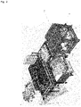
- figure 1 and figure 2 show different views of a thermoforming system according to the invention.
- the heating station 3 is a contact heating field.
- the further heating station 5 is preferably a radiant heating panel.
- the transport system 7 and the forming press 6 are equipped with individually controllable grippers.
- it is rotatable gripper.
- the transport system 7 can, for example, be on one side or on both sides along the direction of passage with individually controllable grippers be equipped.
- the deformation press 6 can, for example, be equipped with individually controllable grippers on one side or on both sides, perpendicularly (stretching in the throughput direction) to the throughput direction.
- the individually controllable grippers are suitable for stretching a composite material in at least one direction. Areal stretching is preferably possible in at least one direction to a different extent over the course of an axis perpendicular to the stretching direction within the stretching plane. This is made possible by the individually controllable grippers, which can exert different amounts of force on the composite material.
- individually controllable grippers attached to one side or both sides of the transport system 7 along the throughput direction can be suitable for stretching the entire assembly transversely to the throughput direction.
- such grippers can be suitable for enabling stretching to different extents over the course of the throughput direction.
- individually controllable grippers (8) mounted on one or both sides of the forming press 6 perpendicularly to the throughput direction are suitable for stretching the overall composite in the throughput direction.
- such grippers (8) are suitable for enabling stretching to different extents over the course of an axis perpendicular to the direction of passage.
- the grippers (8) are suitable for guiding the composite material into the deformation tool 9 following the tool contour.
- the thermoforming system according to the invention can include other devices.
- it can have one or more goods stores 1 for rolled and blank goods, one or more storage tables 2 and/or pick-and-place include stations.
- a storage table 2 can be arranged in front of the heating station 3 in the throughput direction.
- a goods store 1 can be arranged in front of the storage table 2 .
- a goods store 1 can be arranged in front of the further heating station 5 transversely to the throughput direction.
- thermoforming system The individual devices of the thermoforming system according to the invention are characterized in more detail below, without the invention being restricted to these configurations.
- the heating station 3 can in particular comprise a contact heating field.
- the contact heating field can have heating that is controlled on both sides, a gap adjustment and a heating field width that is controlled on both sides.
- the heating field width can be adjusted electrically (motor with spindle), hydraulically, pneumatically or manually (crank with spindle).
- a protective film, in particular a Teflon film, can be stretched over the heating field.
- the (Teflon) foils stretched over the heating field are stretched by means of a spring system and can therefore be adjusted in width.
- the laminating station 4 can also comprise a contact heating field which has the same properties as the one previously described.
- the laminating station can receive and laminate the heated individual layers and/or individual layer composites, which are fed in the throughput direction or to the side of the throughput direction.
- the further heating station 5 can in particular comprise a radiant heating panel.
- the radiant heating field can have an integrated cutting device for cutting a circuit board, for example a carpet, to size.
- the heating intensity can be regulated in heating zones and the radiant heating field can also have a regulated heating field width.
- a multi-layer composite can also be placed under the radiant heating panel.
- Partial assembly of the radiant heating field is also possible using pick-and-place.
- the deformation press 6 with deformation tool 9 is used for shaping.
- the forming press 6 has a stroke controlled on both sides, a tool centering device, a tool clamping device and/or a tool changing system.
- the deformation press 6 can be equipped with grippers that can be adjusted in height and width.
- the gripper system has a controlled stroke and can be adapted to different tool dimensions. Controlled opening and closing of the grippers may be possible.
- the grippers are preferably rotatable and suitable for enabling a controlled subsequent flow of a composite material in accordance with the tool contours.
- the grippers are particularly suitable for stretching a composite material in the throughput direction before and/or during the closing of the mold.
- the grippers can be controlled individually and thus allow stretching in the throughput direction to a different extent via an axis perpendicular to the throughput direction.
- the transport system 7 transports the individual layers, individual layer composites and the overall composite in particular in the direction of flow and can be supplemented by a further transport system 7.1 for transport laterally to the direction of flow.
- the transport system 7 can in particular transport a (lower) fleece sandwich (single layer/single layer composite) in the throughput direction from the heating station 3 to the laminating station 4 and/or to the forming press 6 .
- An overall composite can be transported from the laminating station 4 to the forming press 6, for example.
- the transport system 7.1 can, for example, transport a carpet and optionally further individual layers positioned on it to the laminating station 4 laterally to the throughput direction.
- Both transport systems can have a controlled stroke and be adjustable in height and width to allow adaptation to the tool.
- the transport systems can have grippers with clamping tongs whose opening and closing can be controlled.
- the grippers or clamping tongs can be designed to be rotatable.
- the transport systems are clock-controlled in particular.
- the transport system 7 in the throughput direction can be equipped with individually controllable grippers, in particular rotatable grippers.
- individually controllable grippers in particular rotatable grippers.
- the heated, laminated multilayer composite can be stretched in the direction of passage to different extents in the transverse direction over its length.
- the transport system which is equipped with rotatable grippers, can be particularly suitable for allowing a material composite to flow into the shaping tool 9 in a controlled manner corresponding to the tool contours.
- the goods store 1 can provide rolled or sheet goods.
- the roll can be provided from above or below, whereby the roll can be braked depending on the weight or the roll diameter.
- the goods store can have an automatic edge control, an automatic drive and/or a tension-dependent roll width adjustment.
- a storage table 2 can be suitable for cutting a circuit board of a multi-layer composite or for laying a multi-layer composite. Partial assembly of the device is also possible using pick-and-place stations.
- the following composite material was formed into a floor covering (Skoda Scriptia tool): Dilor carpet (450 g/m 2 PET fibers + 80 g/m 2 latex binding + 80 g/m 2 PE coating); heavy layer (4700 g/m 2 ); Acoustic/stiffening fleece with 40% BiCo fiber content / mixed fiber fleece (700 g/m 2 ).
- Thermoforming Plant In the direction of flow: Goods storage 1 > storage table 2 > contact heating field as heating station 3 > contact heating field as laminating station 4 > forming press 6 with forming tool 9.
- a goods storage 1 and behind it a radiant heating field as an additional heating station 5 were attached at the level of laminating station 4.
- the device corresponded to the figure 1 and 2 illustrated embodiment of the invention.
- the heating station 3 was heated to 220 °C on both sides, the residence time was 39 s, the laminating station 4 was heated to 240 °C on the fleece side and 90 °C on the carpet side, the residence time here was 36 s.
- the shaping tool 9 was heated to 5 °C , the cooling time was 40 s and the die gap was 6mm.
- the fleece was run in the direction of passage.
- the carpet was closed on the side with a heavy foil placed on it; the heavy foil to the radiant heating field (heating station 5); the intensity of 90% was set, the temperature measured on the heavy film was 144° C., the dwell time was 40 s and the distance between the carpet/heavy film and the radiator heating field was 25 mm.
- the fleece After the fleece had been heated, it was transported to the 2nd contact heating field (laminating station 4) by means of the transport system 7; Carpet/heavy film is fed in and laminated at the side with a second transfer system (transport system 7.1). After lamination in the 2nd contact heating field (lamination station 4), the entire laminated composite was transported into the shaping tool 9 and stretched 20% transversely before closing. The cycle time was 60 s.
- the residence times were changed as follows: 1st contact heating field (heating station 3) 35 s, 2nd contact heating field (laminating station 4) 35 s and the cooling time 35 s; the cycle time was 52 s.
- This formed upper fabric also met the quality requirements.
- Thermoforming line In throughput direction: goods store > storage table > contact heating field > deformation tool. A goods store and behind it a radiant heating panel at the level of the contact heating panel were installed to the side of the flow direction.
- the carpet was closed at the side, the carpet back (PE coating) to the radiant heating panel; the intensity of 95% was set, the temperature measured on the back of the carpet was 110° C., the dwell time was 20 s and the distance between the back of the carpet and the radiator heating field was 30 mm.
- the fleece was transported into the contact heating field by means of a transport system, the carpet was fed in at the side with a second transfer system and laminated. After lamination in the contact heating field, the laminated multi-layer composite was transported into the shaping tool and stretched 10% transversely before closing. The cycle time was 55 s.
- the formed upper fabric met the quality requirements.
Landscapes
- Engineering & Computer Science (AREA)
- Mechanical Engineering (AREA)
- Physics & Mathematics (AREA)
- Thermal Sciences (AREA)
- Textile Engineering (AREA)
- Laminated Bodies (AREA)
Description
- Die vorliegende Erfindung betrifft ein Verfahren sowie eine Vorrichtung zur Herstellung von geformten textilen Mehrschichtverbunden. Insbesondere betrifft die Erfindung ein Verfahren, bei dem ein textiler Mehrschichtverbund gelegt und kaschiert sowie verstreckt wird und anschließend zu einer Oberware einer Bodenverkleidung im Automobilbereich geformt wird unter der Maßgabe der Materialeinsparung und Zykluszeitreduzierung.
- Die im Automobilbereich eingesetzten Bodenverkleidungen erfüllen verschiedene Funktionen, denen man bei Design und Herstellung gerecht werden muss. Zum einen bestehen gewisse ästhetische Ansprüche an die Oberflächenoptik sowie eine angenehme Haptik. Die Bodenverkleidung muss weiterhin die Oberflächenkonturen der Karosserie nivellieren sowie Aussparungen, wie beispielsweise für die Fondraumheizung und für Kabelkanäle, ermöglichen. Hinzu treten akustische Funktionen, wie Dämpfung, Schallabsorption und Isolation. Die Anforderungen an die Nutzungseigenschaften umfassen einen geringen Verschleiß, hohe Durchtritts- und Biegefestigkeit, gute Reinigungseignung, hohe Lichtbeständigkeit, Temperatur- und Feuchteresistenz. Die Bodenverkleidung sollte zudem das Einschäumen zusätzlicher Bauteile, die Befestigung von Fußmatten sowie von Teilen zur Erhöhung der Trittfestigkeit und Crasheinleger, aber auch das Aufschweißen von Trittschutz und die Befestigung einer Fußstütze, ermöglichen. In Bezug auf das eingesetzte Material ist die Prozesseignung beziehungsweise die Herstellbarkeit sicherzustellen. Das Material sollte sich durch extreme Tiefziehfähigkeit ohne Funktionseinbußen, Kaschierbarkeit, Durchschäumsicherheit des Materialaufbaus sowie Recyclingfähigkeit auszeichnen. In letzter Zeit hat hierbei auch das Emissionsverhalten enorm an Bedeutung gewonnen.
- Der heute übliche Materialaufbau einer Bodenverkleidung im Automobilbereich umfasst eine Oberware (Nutzschicht), die typischerweise vorwiegend aus einem Teppich besteht, insbesondere aus Tufting, Dilour oder Flachnadelvlies sowie seltener auch aus TPO, PVC oder Gummi, mit verschiedenen Unterschichten. Als Unterschichten kommen häufig Akustik-/Versteifungsvliese, die in der Regel aus PET- und Mischfaservliesen mit enthaltenen BiCo-Fasern gebildet sind, Schwerfolien (partiell oder ganzflächig), basierend auf PE, PP oder EPDM sowie Dichtfolien/Kontaktfolien-Vliese, bestehend aus PE/PA, PE/PA/PE oder PE/PA/PE+PET, zum Einsatz. Den unteren Abschluss bildet eine Isolation aus PUR-Schaumstoff, Vlies oder Faser-Flock-Formteilen.
- Bei Tufting-Teppichen werden als Garnmaterial vorwiegend PA6.6, PA6, PP, rPA(Econyl), PET und rPET sowie die bio-basierenden Polyamide (PA 5.10, PA 6.10) eingesetzt. Übliche Fasermaterialien für Dilour- und FlachnadelvliesTeppiche umfassen PET, PET/PP, PP, PA/PET und rPET, zudem die Bindefasermaterialien PE oder vorzugsweise Mantel-Kern-Zweikomponenten- (BiCo) Fasern, üblicherweise coPET/PET.
- Bei den Tufting-Qualitäten besteht der Tuftingträger zumeist aus PET/PP, PET/coPET oder PET/PA. Die hier angewandten Fasereinbindungen umfassen insbesondere: bei Tufting-Teppich vorwiegend EVA sowie PE und bei den Dilour- und Flachnadelvlies- Teppichen SBR-Latex oder Acrylat; weiterhin bei Dilour- und Flachnadelvlies-Teppichen Folien, Vliese, Klebstoffe (hot melts), thermoplastische Kunststoffe (vorwiegend PE) sowie das thermo bonding (
EP 1 598 476 B1 ). Des Weiteren finden zunehmend Bindefasern, EVA oder thermoplastische Dispersionen Anwendung. Die Beschichtungen, meist als Klebeschicht für Untervliese, aber auch zur Versteifung, umfassen vorwiegend PE oder PP. - Für die Herstellung von Bodenverkleidungen im Automobilbau, der Verformung der Oberware, bei der die Einzelschichten der Oberware als Platinen- oder Rollenware vorliegen, finden sogenannte Thermoverformungs-Anlagen Anwendung. Diese können vollautomatisch, halbautomatisch oder in einem manuellen Verfahren betrieben werden.
- Im Stand der Technik sind Thermoverformungsanlagen mit folgenden Vorrichtungen bekannt, die jeweils in einer Durchlaufrichtung hintereinander angeordnet sind:
- Warenspeicher > Ablagetisch > Kontaktheizfeld > Strahlerheizfeld > Verformungswerkzeug
- Warenspeicher > Ablagetisch > Kontaktheizfeld > Kontaktheizfeld > Verformungswerkzeug
- Warenspeicher > Ablagetisch > Kontaktheizfeld > Verformungswerkzeug
- Warenspeicher > Ablagetisch > Strahlerheizfeld > Verformungswerkzeug
- Der Transport des gelegten Gesamtverbunds erfolgt mittels Transport- und Greifersystemen. Zudem ist auch üblich, mittels pick-and-place, partielle Einzelschichten auf dem Ablagetisch zu platzieren.
- In
DE 10 2004 046 201 B4 undDE 10 2004 054 299 A1 ist ein manuell ausgeführter Heißprägeprozess mittels beheizbarem Formwerkzeug beschrieben, bei dem der Schichtverbund in das Formwerkzeug (als loser Stapel) eingelegt wird. D1 (DE 30 20 595 A1 ) offenbart eine Vorrichtung und ein Verfahren zur Herstellung netzförmiger, synthetischer Harzschaumschichten zur Verwendung als Wärmeisolation- und Verpackungsmaterial. Dabei wird eine Vielzahl linearer Schlitze vorbestimmter Lange in eine Bahn aus thermoplastischem Harzschaum in Längsrichtung der Bahn und in mehreren Reihen, die jeweils einen gleichmäßigen Abstand voneinander besitzen, geschnitten, wobei nebeneinanderliegende Schlitze jeweils zueinander versetzt sind, und die Bahn in einem im wesentlichen rechten Winkel zu den geraden Schlitzen bei einer Temperatur, die das thermoplastische Harz erweichen lasst, gestreckt wird, wobei man die geraden Schlitze zu einer Rautenform oder Sechseckform öffnet. - Im Stand der Technik sind darüber hinaus insbesondere einzelne Vorrichtungen, die als Station einer Thermoverformungsanlage einsetzbar sind, beschrieben.
- In
DE 10 2007 023 755 A1 sind Spannrahmen offenbart, wobei die Spannzangen zumindest anteilig als durchgehend ausgebildete Klemmschienen ausgebildet sind.DE 10 2014 006 968 A1 beschreibt eine Werkzeugstation und ein Verfahren zum Wechseln eines zweiteiligen Werkzeuges.DE 10 2011 008 955 A1 offenbart eine Heizeinrichtung für eine Heizstation, wobei der Heizkörper entlang des Entfernwegs eine Bewegungskomponente aufweist, projizierbar auf die Transportrichtung und der Heizkörper parallel zur Werkstoffbahn bleibt. InDE 20 2006 020 842 U9 ist eine Vorrichtung zum Thermoformen von Kunststofffolien, insbesondere zum Kaschieren von Formkörpern mit einer Kaschierfolie, beschreiben, bei der die Transportbänder in Bewegungsrichtung geteilt sind, diese unterschiedlich schnell angetrieben werden können sowie in Bewegungsrichtung keilförmig auseinanderlaufend angeordnet sind.DE 10 2012 101 925 B4 betrifft eine Heizplattenanordnung, insbesondere zum Verstellen der Arbeitsbreite der Heizplattenanordnung. - In
DE 25 01 366 A1 wird ein Verfahren zur Formgebung von Teppichbahnen mit thermoplastischer Beschichtung mit dem Ziel der Reduzierung der Kühlzeit beschrieben, wobei hierzu das Arbeiten mit Gummituch im Verformungswerkzeug und das Absaugen von Heißlufteinschlüssen im Verformungswerkzeug bei gegebenenfalls gleichzeitigem florseitigen Einblasen von Luft angeführt sind. - Die im Stand der Technik bekannten Verfahren zeichnen sich durch einen geringen Optimierungsgrad in Bezug auf Materialverbrauch und Zyklusszeiten aus.
- Ein weiterer Nachteil der aus dem Stand der Technik bekannten Verfahren ist die Schwierigkeit, bei kurzen Zykluszeiten Wärme in die Materialstruktur des Mehrschichtverbundes einzubringen. Hierbei ist insbesondere die heute übliche Materialstruktur und die Flächengewichte der Oberware zu berücksichtigen:
Tufting Flor 260 bis 700 g/m2 ; Träger 80 bis 140 g/m2 ; Einbindung 50 bis 150 g/m2 Dilour Flor/Faser 300 bis 700 g/m2 ; Einbindung 50 bis 160 g/m2 ; bis 25% BiCo-Faseranteil Beschichtung der Teppiche selbst (Tufting/Dilour) 80 bis 2000 g/m2 Akustik-/Versteifungsvlies 250 bis 1200 g/m2 Schwerfolie (partiell oder ganzflächig) 500 bis 8000 g/m2 Dichtfolien/Kontaktfolien-Vliese 40 bis 260 g/m2 - Zu beachten ist hierbei auch, dass florseitig die Temperaturbeaufschlagung durch das Faser- / das Garnmaterial begrenzt ist und insbesondere Dichtfolien/-schichten nicht durch die anliegende Temperatur zerstört werden dürfen.
- Andererseits sollten im Schichtverbund selbst Temperaturen anliegen, die ein Dehnen / Verstrecken gut ermöglichen (ohne das zum Beispiel Einzelschichten schmelzen, reißen). Bei der Zeit-/Temperaturführung ist auch zu beachten, dass das finale Bauteil den Anforderungen der Automobilindustrie gerecht werden muss. Hier ist insbesondere der Klima-Wechsel-Test (Schrumpf) und das Verschleißverhalten zu nennen.
- Der Materialverbund der Oberwaren besteht zumeist aus mehr als zwei Einzelschichten. In die Einzelschichten, die mit dem Teppich kaschiert werden müssen, ist die für die Kaschierung und Verformung erforderliche Wärme einzubringen. Bei den aus dem Stand der Technik bekannten Anlagen und Verfahren [zum Beispiel: Warenspeicher > Ablagetisch > Kontaktheizfeld > Kontaktheizfeld > Verformungswerkzeug; (Prozessführung nur in Durchlaufrichtung)] ist es nicht realisierbar, die Wärme in den Mehrschichverbund einzubringen, wenn dieser bereits komplett auf dem Ablagetisch gelegt wird; und mittels Transportsystem die einzelnen Prozessschritte durchlaufen muss (in Durchlaufrichtung). Insbesondere dann, wenn Schwerfolien mit Flächengewichten größer 1,5 kg/m2 und Vliese mit Flächengewichten größer 300 g/m2 im Verbund sind.
- Der vorliegenden Erfindung liegt daher die Aufgabe zugrunde, Verfahren und Vorrichtungen zur Herstellung von geformten textilen Mehrschichtverbunden bereitzustellen, die die Nachteile aus dem Stand der Technik vermeiden. Insbesondere sollen der Materialbedarf und die Zykluszeiten verringert werden und das Einbringen der für das Kaschieren und Verformen erforderlichen Wärme auch bei kurzen Zykluszeiten ermöglicht werden.
- Die erfindungsgemäße Aufgabenstellung wird gelöst durch ein Verfahren zur Herstellung von geformten textilen Mehrschichtverbunden, insbesondere Oberwaren von Bodenverkleidungen im Automobilbereich, aus mindestens zwei Einzelschichten und/oder Einzelschichtverbunden, umfassend die folgenden Schritte:
- i. Erwärmen der mindestens zwei Einzelschichten und/oder Einzelschichtverbundeii. Kaschieren der Einzelschichten und/oder Einzelschichtverbunde zu einem Gesamtverbundiii. Formen des Gesamtverbunds in einer Verformungspresse mit einem darinbefindlichen Verformungswerkzeug,dadurch gekennzeichnet, dassa) die Erwärmung von mindestens zwei Einzelschichten und/oder Einzelschichtverbunden unabhängig voneinander erfolgt und die erwärmten Schichten vordem Kaschieren zusammengeführt werden, undb) der Gesamtverbund vor dem Formen in mindestens einer Richtung flächig verstreckt wird, wobei das Ausmaß der Verstreckung über den Verlauf einer Achse senkrecht zur Verstreckungsrichtung innerhalb der Verstreckungsebene unterschiedlich ist, wobei das Verstrecken mithilfe von Greifern durchgeführt wird, die entlang einer Seite des Gesamtverbundes angeordnet werden und einzeln ansteuerbar sind, wobei sich auf diese Weise das Ausmaß der Verstreckung für jeden Greifer einzeln festlegen lässt, so dass über die Seite an der die Greifer angebracht werden in unterschiedlichem Ausmaß in eine Richtung senkrecht zu dieser Seite flächig verstreckt werden kann.
- Das erfindungsgemäße Verfahren zeichnet sich insbesondere dadurch aus, dass die Einzelschichten und/oder Einzelschichtverbunde in separaten Schritten erwärmt werden und vor dem Verformen erst zu einem Gesamtverbund kaschiert werden. Das Kaschieren kann beispielsweise in einer Kaschierstation erfolgen.
- Das erfindungsgemäße Verfahren ermöglicht damit überraschenderweise eine effiziente Prozessführung in Bezug auf das Einbringen der Prozesstemperatur in den Mehrschichtverbund. Damit wird ein bauteilspezifischer Kaschier- und Verformungsprozess gewährleistet. Insbesondere lässt sich die erforderliche Prozesstemperatur in den Materialverbund einbringen, ohne dass Einzelschichten durch ver-/anbrennen, schmelzen oder reißen zerstört werden, womit eine feste und haltbare Kaschierung ermöglicht wird.
- Das erfindungsgemäße Verfahren zeichnet sich darüber hinaus dadurch aus, dass der Gesamtverbund in mindestens einer Richtung flächig verstreckt wird, wobei das Ausmaß der Verstreckung über den Verlauf einer Achse senkrecht zur Verstreckungsrichtung innerhalb der Verstreckungsebene (somit insbesondere längs oder quer) unterschiedlich ist. Überraschenderweise hat sich gezeigt, dass durch flächiges Verstrecken des Gesamtverbunds in mindestens einer Richtung, und insbesondere durch Verstrecken in unterschiedlichem Ausmaß über den Verlauf einer Achse senkrecht zur Verstreckungsrichtung, deutliche Materialeinsparungen realisiert werden können.
- Bei dem herzustellenden Gesamtverbund handelt es sich insbesondere um die Oberware einer Bodenverkleidung im Automobilbereich. Als Einzelschichten und/oder Einzelschichtverbunde kann prinzipiell jede aus dem Stand der Technik bekannt Schicht eingesetzt werden, insbesondere die zuvor beschriebenen Schichten, wie beispielsweise Tufting-, Dilour- oder Flachnadelvliesteppiche sowie Unterschichten in Form von Akustik- und Versteifungsvliesen, Schwerfolien, Dichtfolien- und Kontaktfolienvliese, Gitternetzfolien und Carbonfaservliese.
- Beispielsweise können Akustik-/Versteifungsvliese und gegebenenfalls Dichtfolien und Kontaktfolienvliese sowie Gitternetzfolien und Carbonfaservliese zunächst auf Prozesstemperatur erwärmt werden. Das Erwärmen kann insbesondere in einer ersten Kontaktheizung (Heizstation) erfolgen.
- Ein Teppich und gegebenenfalls weitere Vliese und/oder Schwerfolien können unabhängig davon erwärmt werden, beispielsweise in einem Strahlerheizfeld.
- Die so erwärmten Schichten werden im Anschluss zusammengeführt und zu einem Gesamtverbund (Oberware) kaschiert, beispielsweise in einer Kaschierstation in Form eines Kontaktheizfeldes.
- Die Temperatur- und Zeit-Einstellungen in den Heiz- und Kaschierstationen werden durch die Materialtypen der Einzel- und Einzelschichtverbunde, insbesondere bei den Teppichtypen auch durch den Fasermix -mit und ohne Mantel-Kern-Zweikomponenten- (BiCo) Fasern, bestimmt.
- Nach dem Kaschieren wird der Gesamtverbund in einer Verformungspresse mit einem Verformungswerkzeug geformt. Hierzu wird der Gesamtverbund von einer Kaschierstation zur Verformungspresse transportiert. Die Prozesstemperatur im Verformungswerkzeug liegt vorzugsweise in einem Bereich von -5 bis +25 °C. Besonders bevorzugt sind Temperaturen in einem Bereich von 0 bis 7 °C. Die Verweilzeit im Verformungswerkzeug liegt vorzugsweise in einem Bereich von 25 bis 95 Sekunden, bevorzugt 35 bis 72 Sekunden.
- In einer alternativen Ausführungsform können Kaschieren und Verformen in einem Arbeitsschritt durchgeführt werden. Diese Variante ist besonders bevorzugt, wenn ein Gesamtverbund aus einem Teppich und einem einzelnen (Unter)Vlies hergestellt werden soll. Hierbei kann beispielsweise ein (Unter)Vlies zugeschnitten werden und auf Prozesstemperatur erwärmt werden, insbesondere in einem Kontaktheizfeld. Unabhängig davon wird ein zugeschnittener Teppich erwärmt, beispielsweise in einem Strahlerheizfeld. Die Schichten werden in Kontakt gebracht und in einem Schritt gleichzeitig kaschiert und geformt. Dieser Schritt kann insbesondere in einer Verformungspresse mit einem Verformungswerkzeug durchgeführt werden.
- Erfindungsgemäß wird der erwärmte Gesamtverbund vor dem Formen in mindestens einer Richtung flächig verstreckt. Erfolgt das Formen in einer Verformungspresse, kann das Verstrecken vor und/oder während des Schließens der Verformungspresse stattfinden. Das Ausmaß der Verstreckung ist über den Verlauf einer Achse senkrecht zur Verstreckungsrichtung innerhalb der Verstreckungsebene unterschiedlich.
- Bevorzugt wird der erwärmte Gesamtverbund während des Transports zur Verformungspresse verstreckt. Findet das Kaschieren und das Formen in verschiedenen Stationen statt, wird der Gesamtverbund vorzugsweise nach dem Kaschieren verstreckt. In einer alternativen Ausführungsform kann der Gesamtverbund auch in der Verformungspresse vor und/oder während des Schließens der Verformungspresse verstreckt werden.
- Bevorzugt wird der erwärmte Gesamtverbund über den Verlauf seiner Längsseite in unterschiedlichem Ausmaß in Querrichtung verstreckt. Alternativ wird der Gesamtverbund über den Verlauf seiner Querseite in unterschiedlichem Ausmaß in Längsrichtung verstreckt. Der Gesamtverbund kann auch in mehrere unabhängige Richtungen verstreckt werden, insbesondere sowohl in Querrichtung als auch in Längsrichtung.
- Das Ausmaß der Verstreckung beträgt vorzugsweise in Längsrichtung (Durchlaufrichtung) zwischen 5% und 20%; und in Querrichtung zwischen 5% und 35%.
- Das Verstrecken kann beispielsweise mithilfe von Greifern durchgeführt werden, die entlang einer Seite des Gesamtverbunds angeordnet werden und einzeln ansteuerbar sind. Auf diese Weise lässt sich das Ausmaß der Verstreckung für jeden Greifer einzeln festlegen, sodass über die Seite an der die Greifer angebracht werden in unterschiedlichem Ausmaß in eine Richtung senkrecht zu dieser Seite flächig verstreckt werden kann.
- Die Greifer können beispielsweise Teil eines Transportsystems sein, mit dem der Gesamtverbund von der Kaschierstation zur Verformungspresse transportier wird. Insbesondere kann der Gesamtverbund während des Transports durch Greifer am Transportsystems Querrichtung bezogen auf die Transportrichtung verstreckt werden. Das Verstrecken kann jedoch auch noch in der Kaschierstation, nach deren Öffnung oder auch in der Verformungspresse durchgeführt werden.
- Die Greifer können auch Teil der Verformungspresse sein. Insbesondere kann der Gesamtverbund durch an der Verformungspresse angebrachte Greifer vor und/oder während des Schließens des Verformungswerkzugs in Längsrichtung bezogen auf die Transportrichtung verstreckt werden.
- In einer bevorzugten Ausführungsform wird der Gesamtverbund werkzeug-konturfolgend in das sich schließende Verformungswerkzeug transportiert. Insbesondere kann der Gesamtverbund durch drehbare Greifer (Klemmzangen im Greifer) am Transportsystem und durch die Greifer in/an der Verformungspresse geführt in das sich schließende Verformungswerkzeug transportiert werden. Das Nachfließen des Verbundes ist somit steuerbar. Dies ermöglicht das Führen des Verbundes in Korrelation zur Kontur des Verformungswerkzeuges (Reduzierung des Ausziehgrades, Vermeidung von Faltenbildung).
- In einer weiteren Ausführungsform wird die erfindungsgemäße Aufgabenstellung gelöst durch eine Thermoverformungsanlage zur Herstellung von verformten textilen Mehrschichtverbunden, insbesondere von Oberwaren von Bodenverkleidungen im Automobilbereich, umfassend eine Heizstation 3, eine Kaschierstation 4, eine weitere Heizstation 5, eine Verformungspresse 6 mit einem Verformungswerkzeug 9 und mindestens ein Transportsystem 7, wobei das Transportsystem zum Transport von Einzelschichten und/oder Einzelschichtverbunden zwischen den Stationen - sowie auch des Gesamtverbunds - geeignet ist, dadurch gekennzeichnet, dass
- a) die Heizstation 3, die Kaschierstation 4 und die Verformungspresse 6 eine Durchlaufrichtung bilden und die weitere Heizstation 5 seitlich zu dieser Durchlaufrichtung angeordnet ist,
- b) das Transportsystem 7 einseitig oder beidseitig entlang der Durchlaufrichtung mit einzeln ansteuerbaren, insbesondere drehbaren, Greifern ausgerüstet ist, und
- c) die Verformungspresse 6 einseitig oder beidseitig senkrecht zur Durchlaufrichtung mit einzeln ansteuerbaren, insbesondere drehbaren, Greifern 8 ausgerüstet ist, wobei
- Die erfindungsgemäße Thermoverformungsanlage ist zur Durchführung des erfindungsgemäßen Verfahrens geeignet. Insbesondere eignet sich die Vorrichtung zur Herstellung von Oberware einer Bodenverkleidung im Automobilbereich. Beispielsweise können Akustik-/Versteifungsvliese und gegebenenfalls Dichtfolien und Kontaktfolienvliese, des Weiteren Gitternetzfolien und Carbonfaservliese in der Heizstation 3 zunächst auf Prozesstemperatur erwärmt werden. Unabhängig davon kann ein Teppich und gegebenenfalls weitere Vlies und/oder Schwerfolien in der seitlich angeordneten weiteren Heizstation 5 erwärmt werden. Mithilfe des Transportsystems 7 können die erwärmten Einzelschichten und/oder Einzelschichtverbunde in die Kaschierstation 4 transportiert, dort kaschiert und dann in die Verformungspresse 6 transportiert und dort geformt werden.
- Die erfindungsgemäße Thermoverformungsanlage kann neben dem in Durchlaufrichtung arbeitenden Transportsystem 7 ein weiteres Transportsystem 7.1 aufweisen, welches quer zur Durchlaufrichtung arbeitet und die in der weiteren Heizstation 5 erwärmten Einzelschichten und/oder Einzelschichtverbunde zu den Stationen in Durchlaufrichtung transportiert.
- In einer bevorzugten Ausführungsform umfasst die Thermoverformungsanlage weiterhin eine Kaschierstation 4, die in Durchlaufrichtung zwischen der Heizstation 3 und der Verformungspresse 6 angeordnet ist. Die Kaschierstation 4 umfasst insbesondere ein Kontaktheizfeld. In dieser Ausführungsform ist die weitere Heizstation 5 bevorzugt seitlich zur Kaschierstation 4 angeordnet. Die Einzelschichten und/oder Einzelschichtverbunde können wie zuvor beschrieben in der Heizstation 3 und der weiteren Heizstation 5 erwärmt werden und anschließend in der Kaschierstation 4 kaschiert werden und mithilfe des Transportsystems 7 zum Formen in die Verformungspresse 6 transportiert werden. In der Verformungspresse 6 befindet sich das Verformungswerkzeug 9; sowie an der Verformungspresse 6 das Greifersystem 8.
-
Figur 1 undFigur 2 zeigen verschiedene Ansichten einer erfindungsgemäßen Thermoverformungsanlage. - In einer bevorzugten Ausführungsform handelt es sich bei der Heizstation 3 um ein Kontaktheizfeld. Bei der weiteren Heizstation 5 handelt es sich bevorzugt um ein Strahlerheizfeld.
- Erfindungsgemäß sind das Transportsystem 7 und die Verformungspresse 6 mit einzeln ansteuerbaren Greifern ausgerüstet. Insbesondere handelt es sich um drehbare Greifer. Das Transportsystem 7 kann beispielsweise einseitig oder beidseitig entlang der Durchlaufrichtung mit einzeln ansteuerbaren Greifern ausgerüstet sein. Die Verformungspresse 6 kann beispielsweise einseitig oder beidseitig senkrecht (Verstreckung in Durchlaufrichtung) zur Durchlaufrichtung mit einzeln ansteuerbaren Greifern ausgerüstet sein.
- Die einzeln ansteuerbaren Greifer sind geeignet, einen Materialverbund in mindestens einer Richtung zu verstrecken. Vorzugsweise ist eine flächige Verstreckung in mindestens einer Richtung in unterschiedlichem Ausmaß über den Verlauf einer Achse senkrecht zur Verstreckungsrichtung innerhalb der Verstreckungsebene möglich. Dies wird durch die einzeln ansteuerbaren Greifer ermöglicht, die in unterschiedlichem Ausmaß eine Kraft auf den Materialverbund ausüben können.
- Beispielsweise können einseitig oder beidseitig am Transportsystem 7 entlang der Durchlaufrichtung angebrachte einzeln ansteuerbare Greifer geeignet sein, den Gesamtverbund quer zur Durchlaufrichtung zu verstrecken. Insbesondere können solche Greifer geeignet sein, die Verstreckung in unterschiedlichem Ausmaß über den Verlauf der Durchlaufrichtung zu ermöglichen.
- Beispielsweise sind einseitig oder beidseitig an der Verformungspresse 6 senkrecht zur Durchlaufrichtung angebrachte einzeln ansteuerbare Greifer (8) geeignet, den Gesamtverbund in Durchlaufrichtung zu verstrecken. Insbesondere sind solche Greifer (8) geeignet, die Verstreckung in unterschiedlichem Ausmaß über den Verlauf einer Achse senkrecht zur Durchlaufrichtung zu ermöglichen.
- In einer weiteren bevorzugten Ausführungsform sind die Greifer (8) geeignet, den Materialverbund werkzeug-konturfolgend in das Verformungswerkzeug 9 zu führen.
- Die erfindungsgemäße Thermoverformungsanlage kann weitere Vorrichtungen umfassen. Insbesondere kann sie einen oder mehrere Warenspeicher 1 für Rollen- und Platinenware, einen oder mehrere Ablagetische 2 und/oder pick-and-place Stationen umfassen. Beispielsweise kann ein Ablagetisch 2 in Durchlaufrichtung vor der Heizstation 3 angeordnet sein. Vor dem Ablagetisch 2 kann insbesondere ein Warenspeicher 1 angeordnet sein. Quer zur Durchlaufrichtung kann beispielsweise ein Warenspeicher 1 vor der weiteren Heizstation 5 angeordnet sein.
- Im Folgenden werden die einzelnen Vorrichtungen der erfindungsgemäßen Thermoverformungsanlage näher charakterisiert, ohne dass die Erfindung auf diese Ausgestaltungen beschränkt wäre.
- Die Heizstation 3 kann insbesondere ein Kontaktheizfeld umfassen. Beispielsweise kann das Kontaktheizfeld über eine doppelseitig geregelte Beheizung, eine Spaltmaßeinstellung sowie eine doppelseitig geregelte Heizfeldbreite verfügen. Die Heizfeldbreiteneinstellung kann elektrisch (Motor mit Spindel), hydraulisch, pneumatisch oder per Hand (Kurbel mit Spindel) erfolgen. Über das Heizfeld kann eine Schutzfolie, insbesondere eine Teflonfolie gespannt sein. Die über das Heizfeld gespannten (Teflon-)Folien sind mittels Federsystem gespannt und somit in der Breite anpassbar.
- Die Kaschierstation 4 kann ebenfalls ein Kontaktheizfeld umfassen, das die gleichen Eigenschaften wie das zuvor beschriebene aufweist. Die Kaschierstation kann die erwärmten Einzelschichten und/oder Einzelschichtverbunde, die in Durchlaufrichtung oder seitlich zur Durchlaufrichtung zugeführt werden, aufnehmen und kaschieren.
- Die weitere Heizstation 5 kann insbesondere ein Strahlerheizfeld umfassen. Das Strahlerheizfeld kann eine integrierte Schneidevorrichtung zum Zuschneiden einer Platine, beispielsweise eines Teppichs, aufweisen. Die Heizintensität kann in Heizzonen regelbar sein und das Strahlerheizfeld zudem eine geregelte Heizfeldbreite aufweisen. Ein Mehrschichtverbund kann auch unter dem Strahlerheizfeld gelegt werden.
- Mittels pick-and-place ist auch eine partielle Bestückung des Strahlerheizfelds möglich.
- Die Verformungspresse 6 mit Verformungswerkzeug 9 dient der Formgebung. Insbesondere verfügt die Verformungspresse 6 über einen doppelseitig geregelten Hub, eine Werkzeugzentriervorrichtung, eine Werkzeugspannvorrichtung und/oder ein Werkzeugwechselsystem.
- Die Verformungspresse 6 kann mit höhen- und breitenverstellbaren Greifern ausgerüstet sein. Das Greifersystem verfügt insbesondere über einen geregelten Hub und lässt sich an verschiedene Werkzeugabmessungen anpassen. Ein gesteuertes Öffnen und Schließen der Greifer kann möglich sein. Bevorzugt sind die Greifer drehbar und geeignet, ein gesteuertes Nachfließen eines Materialverbunds entsprechend der Werkzeugkonturen zu ermöglichen. Die Greifer sind insbesondere geeignet, einen Materialverbund vor und/oder während des Schließens des Werkzeugs in Durchlaufrichung zu verstrecken. Die Greifer können einzeln ansteuerbar sein und damit ein Verstrecken in Durchlaufrichtung in unterschiedlichem Ausmaß über eine Achse senkrecht zur Durchlaufrichtung ermöglichen.
- Das Transportsystem 7 transportiert die Einzelschichten, Einzelschichtverbunde sowie den Gesamtverbund insbesondere in Durchlaufrichtung und kann durch ein weiteres Transportsystem 7.1 zum Transport seitlich zur Durchlaufrichtung ergänzt sein. Das Transportsystem 7 kann insbesondere ein (Unter-)Vlies-Sandwich (Einzelschicht/Einzelschichtverbund) in Durchlaufrichtung von der Heizstation 3 zur Kaschierstation 4 und/oder zur Verformungspresse 6 transportieren. Ein Gesamtverbund kann beispielsweise von der Kaschierstation 4 zur Verformungspresse 6 transportiert werden. Das Transportsystem 7.1 kann beispielweise einen Teppich und gegebenenfalls weitere darauf positionierte Einzelschichten seitlich zur Durchlaufrichtung zur Kaschierstation 4 transportieren.
- Beide Transportsysteme können einen geregelten Hub aufweisen und höhen- und breitenverstellbar sein, um die Anpassung an das Werkzeug zu ermöglichen. Die Transportsysteme können Greifer mit Klemmzangen aufweisen, deren Öffnen und Schließen steuerbar ist. Die Greifer beziehungsweise Klemmzangen können drehbar ausgestaltet sein. Die Transportsysteme sind insbesondere taktgesteuert.
- Insbesondere das Transportsystem 7 in Durchlaufrichtung kann mit einzeln ansteuerbaren Greifern, insbesondere drehbaren Greifern, ausgerüstet sein. Damit kann der erwärmte, kaschierte Mehrschichtverbund in Durchlaufrichtung über die Länge in unterschiedlichem Ausmaß in Querrichtung verstreckt werden.
- Das mit drehbaren Greifern ausgestatte Transportsystem kann insbesondere geeignet sein, ein gesteuertes Nachfließen eines Materialverbunds entsprechend der Werkzeugkonturen in das Verformungswerkzeug 9 zu ermöglichen.
- Der Warenspeicher 1 kann eine Rollen- oder Plattenware bereitstellen. Die Rolle kann von oben oder unten bereitgestellt werden, wobei eine gewichts- oder Rollendurchmesser-abhängige Rollenbremsung erfolgen kann. Der Warenspeicher kann eine automatische Kantensteuerung, einen automatischen Antrieb und/oder eine spannungsabhängige Rollenbreitenverstellung aufweisen.
- Ein Ablagetisch 2 kann geeignet sein, eine Platine eines Mehrschichtverbunds zuzuschneiden oder einen Mehrschichtverbund zu legen. Mittels pick-and-place-Stationen ist auch eine partielle Bestückung der Vorrichtung möglich.
- Der folgende Materialverbund wurde zu einer Bodenverkleidung (Werkzeug Skoda Octavia) verformt:
Dilour-Teppich (450 g/m2 PET-Fasern + 80 g/m2 Latex-Einbindung + 80 g/m2 PE-Beschichtung); Schwerschicht (4700 g/m2); Akustik-/Versteifungsvlies mit 40% BiCo-Faser-Anteil / Mischfaservlies (700 g/m2). - Thermo-Verformungs-Anlage:
In Durchlaufrichtung: Warenspeicher 1 > Ablagetisch 2 > Kontaktheizfeld als Heizstation 3 > Kontaktheizfeld als Kaschierstation 4 > Verformungspresse 6 mit Verformungswerkzeug 9. Seitlich zur Durchlaufrichtung war ein Warenspeicher 1 und dahinter ein Strahlerheizfeld als weitere Heizstation 5 auf Höhe der Kaschierstation 4 angebracht. Die Vorrichtung entsprach der inFigur 1 und2 dargestellten Ausführungsform der Erfindung. - Die Heizstation 3 war beidseitig auf 220 °C temperiert, die Verweilzeit betrug 39 s, die Kaschierstation 4 war vliesseitig auf 240 °C und teppichseitig auf 90 °C temperiert, die Verweilzeit betrug hier 36 s. Das Verformungswerkzeug 9 war auf 5 °C temperiert, die Kühlzeit betrug 40 s und der Werkzeugspalt 6mm. In Durchlaufrichtung wurde das Vlies gefahren.
- Seitlich wurde der Teppich mit aufgelegter Schwerfolie zugefahren; die Schwerfolie zum Strahlerheizfeld (Heizstation 5); die Intensität von 90% wurde eingestellt, die gemessene Temperatur auf der Schwerfolie betrug 144 °C, die Verweilzeit betrug 40 s und der Abstand Teppich/Schwerfolie zum Strahlerheizfeld war 25 mm.
- Nach Erwärmung des Vlieses wurde dieses mittels Transportsystem 7 in das 2. Kontaktheizfeld (Kaschierstation 4) transportiert; seitlich Teppich/Schwerfolie mit einem zweiten Transfersystem (Transportsystem 7.1) zugefahren und kaschiert. Nach der Kaschierung im 2. Kontaktheizfeld (Kaschierstation 4) wurde der kaschierte Gesamtverbund in das Verformungwerkzeug 9 transportiert und vor dem Schließen 20% querverstreckt. Die Zykluszeit betrug 60 s.
- Die so hergestellte Bodenverkleidung (Oberware) entsprach den Qualitätsanforderungen der Automobilindustrie.
- In einem zweiten Schritt wurden die Verweilzeiten wie folgt verändert:
1. Kontaktheizfeld (Heizstation 3) 35 s, 2. Kontaktheizfeld (Kaschierstation 4) 35 s und die Kühlzeit 35 s; die Zykluszeit betrug 52 s. Auch diese verformte Oberware entsprach den Qualitätsanforderungen. - Der folgende Materialverbund wurde zu einer Bodenverkleidung (Werkzeug Skoda Octavia) verformt:
- Tufting-Teppich (360 g/m2 PA6-Garn + 380 g/m2 PE-Beschichtung);
- Akustik-/Versteifungsvlies (600 g/m2 PET-Fasern mit 20% BiCo-Faser-Anteil).
- Thermoverformungsanlage :
In Durchlaufrichtung: Warenspeicher > Ablagetisch > Kontaktheizfeld > Verformungswerkzeug. Seitlich zur Durchlaufrichtung war ein Warenspeicher und dahinter ein Strahlerheizfeld auf Höhe des Kontaktheizfelds angebracht. - Zum Einsatz kam nur ein Kontaktheizfeld (Kaschierung), mit den folgenden Einstellungen: vliesseitig 240 °C und teppichseitig 85 °C, Verweilzeit 40 s. Das Verformungswerkzeug war auf 5 °C temperiert, die Kühlzeit betrug 40 s und der Werkzeugspalt 6 mm. In Durchlaufrichtung wurde das PET-Vlies gefahren.
- Seitlich wurde der Teppich zugefahren, die Teppichrückseite (PE-Beschichtung) zum Strahlerheizfeld; die Intensität von 95% wurde eingestellt, die gemessene Temperatur auf der Teppichrückseite betrug 110 °C, die Verweilzeit betrug 20 s und der Abstand Teppichrückseite zum Strahlerheizfeld 30 mm.
- Das Vlies wurde mittels Transportsystem in das Kontaktheizfeld transportiert, seitlich der Teppich mit einem zweiten Transfersystem zugefahren und kaschiert. Nach der Kaschierung im Kontaktheizfeld wurde der kaschierte Mehrschichtverbund in das Verformungwerkzeug transportiert und vor dem Schließen 10% querverstreckt. Die Zykluszeit betrug 55 s. Die verformte Oberware entsprach den Qualitätsanforderungen.
Claims (9)
- Verfahren zur Herstellung von geformten textilen Mehrschichtverbunden, aus mindestens zwei Einzelschichten und/oder Einzelschichtverbunden, umfassend die folgenden Schritte:i. Erwärmen der mindestens zwei Einzelschichten und/oder Einzelschichtverbundeii. Kaschieren der Einzelschichten und/oder Einzelschichtverbunde zu einem Gesamtverbundiii. Formen des Gesamtverbunds in einer Verformungspresse mit einem darin befindlichen Verformungswerkzeug,dadurch gekennzeichnet, dassa) die Erwärmung von mindestens zwei Einzelschichten und/oder Einzelschichtverbunden unabhängig voneinander erfolgt und die erwärmten Schichten vor dem Kaschieren zusammengeführt werden, undb) der Gesamtverbund vor dem Formen in mindestens einer Richtung flächig verstreckt wird, wobei das Ausmaß der Verstreckung über den Verlauf einer Achse senkrecht zur Verstreckungsrichtung innerhalb der Verstreckungsebene unterschiedlich ist, wobei das Verstrecken mithilfe von Greifern durchgeführt wird, die entlang einer Seite des Gesamtverbundes angeordnet werden und einzeln ansteuerbar sind, wobei sich auf diese Weise das Ausmaß der Verstreckung für jeden Greifer einzeln festlegen lässt, so dass über die Seite an der die Greifer angebracht werden in unterschiedlichem Ausmaß in eine Richtung senkrecht zu dieser Seite flächig verstreckt werden kann.
- Verfahren gemäß Anspruch 1, dadurch gekennzeichnet, dass mindestens ein(e) unabhängig erwärmte(r) Einzelschicht/Einzelschichtverbund ausgewählt ist aus Akustik- und Versteifungsvliesen, Dichtfolien, Kontaktfolienvliesen, Gitternetzfolien, Carbonfaservliese und deren Mehrschichtverbunden.
- Verfahren gemäß Anspruch 1 oder 2, dadurch gekennzeichnet, dass mindestens ein(e) unabhängig erwärmte(r) Einzelschicht/Einzelschichtverbund ausgewählt ist aus Tufting-, Dilour- und Flachnadelvliesteppichen, Schwerfolien und deren Mehrschichtverbunden.
- Verfahren gemäß einem der Ansprüche 1 bis 3, dadurch gekennzeichnet, dass die Schritte des Kaschierens und Verformens in einem Schritt in der Verformungspresse oder in zwei Schritten erfolgen.
- Verfahren gemäß einem der Ansprüche 1 bis 4, dadurch gekennzeichnet, dass der Gesamtverbund vor dem Formen über den Verlauf einer Längsseite in unterschiedlichem Ausmaß in Querrichtung und/oder über den Verlauf einer Querseite in unterschiedlichem Ausmaß in Längsrichtung verstreckt wird.
- Verfahren gemäß einem der Ansprüche 1 bis 5, dadurch gekennzeichnet, dass der Gesamtverbund werkzeugkonturfolgend in das sich schließende Verformungswerkzeug transportiert wird.
- Thermoverformungsanlage zur Herstellung von verformten textilen Mehrschichtverbunden, umfassend eine Heizstation (3), eine Kaschierstation (4), eine weitere Heizstation (5), eine Verformungspresse (6) mit einem Verformungswerkzeug (9) und mindestens ein Transportsystem (7), wobei das Transportsystem zum Transport von Einzelschichten und/oder Einzelschichtverbunden zwischen den Stationen geeignet ist, dadurch gekennzeichnet, dassa) die Heizstation (3), die Kaschierstation (4) und die Verformungspresse (6) eine Durchlaufrichtung bilden und die weitere Heizstation (5) seitlich zu dieser Durchlaufrichtung angeordnet ist,b) das Transportsystem (7) einseitig oder beidseitig entlang der Durchlaufrichtung mit einzeln ansteuerbaren, Greifern ausgerüstet ist, undc) die Verformungspresse (6) einseitig oder beidseitig senkrecht zur Durchlaufrichtung mit einzeln ansteuerbaren, insbesondere drehbaren, Greifern (8) ausgerüstet ist, wobei die einzelnen ansteuerbaren Greifer geeignet sind, einen Materialverbund in Durchlaufrichtung und/oder quer zur Durchlaufrichtung zu versrecken, wobei für mindestens eine Verstreckungsrichtung das Ausmaß der Verstreckung über den Verlauf einer Achse senkrecht zur Verstreckungsrichtung innerhalb der Verstreckungsebene, und somit längs und/oder quer, unterschiedlich ist und die einzeln ansteuerbaren Greifer geeignet sind einen Materialverbund werkzeugkonturfolgend in das Verformungswerkzeug (9) zu führen.
- Thermoverformungsanlage gemäß Anspruch 7, dadurch gekennzeichnet, dass es sich bei der Heizstation (3) und/oder der Kaschierstation (4) um ein Kontaktheizfeld handelt.
- Thermoverformungsanlage gemäß einem der Ansprüche 7 oder 8, dadurch gekennzeichnet, dass es sich bei der seitlichen Heizstation (5) um ein Strahlerheizfeld handelt.
Applications Claiming Priority (2)
| Application Number | Priority Date | Filing Date | Title |
|---|---|---|---|
| DE102018114125.4A DE102018114125A1 (de) | 2018-06-13 | 2018-06-13 | Verfahren und Vorrichtung zur Herstellung von geformten textilen Mehrschichtverbunden |
| PCT/EP2019/063625 WO2019238398A1 (de) | 2018-06-13 | 2019-05-27 | Verfahren und vorrichtung zur herstellung von geformten textilen mehrschichtverbunden |
Publications (2)
| Publication Number | Publication Date |
|---|---|
| EP3807067A1 EP3807067A1 (de) | 2021-04-21 |
| EP3807067B1 true EP3807067B1 (de) | 2022-09-28 |
Family
ID=66668938
Family Applications (1)
| Application Number | Title | Priority Date | Filing Date |
|---|---|---|---|
| EP19726994.7A Active EP3807067B1 (de) | 2018-06-13 | 2019-05-27 | Verfahren und vorrichtung zur herstellung von geformten textilen mehrschichtverbunden |
Country Status (3)
| Country | Link |
|---|---|
| EP (1) | EP3807067B1 (de) |
| DE (1) | DE102018114125A1 (de) |
| WO (1) | WO2019238398A1 (de) |
Cited By (1)
| Publication number | Priority date | Publication date | Assignee | Title |
|---|---|---|---|---|
| EP4523971A3 (de) * | 2023-09-14 | 2025-05-07 | OMI Group srl | Kunstfaserplatte und verfahren zu ihrer herstellung |
Families Citing this family (6)
| Publication number | Priority date | Publication date | Assignee | Title |
|---|---|---|---|---|
| DE102020127588B4 (de) | 2020-10-20 | 2025-06-18 | Adler Pelzer Holding Gmbh | Absorptive Schallisolation |
| CN114516157B (zh) * | 2020-11-18 | 2023-04-07 | 比亚迪股份有限公司 | 复合夹芯板热压成型冷却定型装置 |
| DE102021101921A1 (de) | 2021-01-28 | 2022-07-28 | Adler Pelzer Holding Gmbh | Schallisolierung mit mehrschichtiger Faser-Isolation; und Verfahren zu deren Herstellung |
| DE102021101922A1 (de) | 2021-01-28 | 2022-07-28 | Adler Pelzer Holding Gmbh | Schallisolierung mit mehrschichtiger Faser-Isolation; und Verfahren zu deren Herstellung |
| DE102021108602A1 (de) | 2021-04-07 | 2022-10-13 | Adler Pelzer Holding Gmbh | Verfahren zur Herstellung einer Schallisolierung mit Vlies-Isolation und Schallisolierung |
| DE102023104422A1 (de) | 2023-02-23 | 2024-08-29 | Adler Pelzer Holding Gmbh | Verfahren zur Herstellung einer Schallisolierung |
Family Cites Families (11)
| Publication number | Priority date | Publication date | Assignee | Title |
|---|---|---|---|---|
| DE2501366A1 (de) | 1975-01-15 | 1976-07-22 | Kiefel Gmbh Paul | Verfahren zur formgebung von teppichbahnen mit thermoplastischer beschichtung |
| DE3020595A1 (de) * | 1979-05-30 | 1980-12-11 | Hisashi Ogura | Vorrichtung und verfahren zur herstellung netzfoermiger, synthetischer harzschaumschichten zur verwendung als waermeisolations- und verpackungsmaterial |
| US6835266B2 (en) * | 2001-08-02 | 2004-12-28 | Lear Corporation | Shuttle system for manufacturing vehicle headliners |
| NL1026245C2 (nl) | 2004-05-21 | 2005-11-22 | Klieverik Heli Bv | Werkwijze voor het vervaardigen van tapijt. |
| DE102004046201B4 (de) | 2004-09-22 | 2007-08-02 | Carcoustics Tech Center Gmbh | Hinterschäumtes Teppichformteil für Kraftfahrzeuge und Verfahren zu dessen Herstellung |
| DE102004054299A1 (de) | 2004-11-09 | 2006-05-11 | Carcoustics Tech Center Gmbh | Akustisch wirksames Teppichformteil für Kraftfahrzeuge und Verfahren zu dessen Herstellung |
| DE102006048296C5 (de) | 2006-10-12 | 2015-04-02 | Frimo Group Gmbh | Verfahren zum Herstellen einer Innenraumverkleidung |
| DE102007023755A1 (de) | 2007-05-22 | 2008-11-27 | Frimo Group Gmbh | Spannrahmen für eine Thermoformanlage |
| DE102011008955A1 (de) | 2010-06-07 | 2011-12-08 | Kiefel Gmbh | Heizeinrichtung, Heizstation und Thermoformanlage sowie hiermit hergestelltes Produkt |
| DE102012101925B4 (de) | 2012-03-07 | 2014-07-10 | Hollmann Sondermaschinen Gmbh | Heizplattenanordnung für eine Verformungsanlage, insbesondere zur Verformung von Teppichen sowie Verfahren zur Verstellung der Arbeitsbreite einer Heizplattenanordnung |
| DE102014006968A1 (de) | 2013-05-14 | 2014-12-18 | Kiefel Gmbh | Werkzeugstation einer Thermoformanlage, Thermoformanlage und Verfahren zum Wechseln eines zweiteiligen Werkzeugs an einer Thermoformanlage |
-
2018
- 2018-06-13 DE DE102018114125.4A patent/DE102018114125A1/de active Pending
-
2019
- 2019-05-27 EP EP19726994.7A patent/EP3807067B1/de active Active
- 2019-05-27 WO PCT/EP2019/063625 patent/WO2019238398A1/de not_active Ceased
Cited By (1)
| Publication number | Priority date | Publication date | Assignee | Title |
|---|---|---|---|---|
| EP4523971A3 (de) * | 2023-09-14 | 2025-05-07 | OMI Group srl | Kunstfaserplatte und verfahren zu ihrer herstellung |
Also Published As
| Publication number | Publication date |
|---|---|
| WO2019238398A1 (de) | 2019-12-19 |
| EP3807067A1 (de) | 2021-04-21 |
| DE102018114125A1 (de) | 2019-12-19 |
Similar Documents
| Publication | Publication Date | Title |
|---|---|---|
| WO2019238398A1 (de) | Verfahren und vorrichtung zur herstellung von geformten textilen mehrschichtverbunden | |
| EP2525962B1 (de) | Sandwichbauteil und verfahren zu dessen herstellung | |
| EP3083249B1 (de) | Verfahren zum herstellen eines sandwichbauteils | |
| EP2925499A1 (de) | Verfahren zum herstellen eines strukturbauteils, insbesondere für eine karosserie | |
| WO2022214235A1 (de) | Verfahren zur herstellung einer schallisolierung mit vlies-isolation und schallisolierung | |
| WO2022161717A1 (de) | Schallisolierung mit mehrschichtiger faser-isolation; und verfahren zu deren herstellung | |
| DE102022121174B3 (de) | Isolationsbauteil-herstellungsverfahren sowie strömungsdichtes, leichtes isolationsbauteil für fahrzeuge | |
| WO2022161718A1 (de) | Verfahren zur herstellung einer schallisolierenden bodenverkleidung mit mehrschichtiger faser-isolation | |
| EP2737987B1 (de) | Verfahren und Vorrichtung zur Herstellung eines Innenverkleidungsteils | |
| EP2101998B1 (de) | Thermoplastische folie mit geschäumter deckfolie | |
| DE4228282C2 (de) | Hinterspritztes Formteil sowie Verfahren zur Herstellung desselben | |
| WO2013026571A1 (de) | Innenverkleidungteil sowie verfahren zu seiner herstellung | |
| EP3807127B1 (de) | Dreidimensional geformtes nadelvlies | |
| DE102023104422A1 (de) | Verfahren zur Herstellung einer Schallisolierung | |
| DE102012219123B4 (de) | Herstellungsverfahren für Dekormaterial mit Pfeifen-Optik und entsprechendes Dekormaterial | |
| DE102016222392B4 (de) | Verfahren zum Herstellen einer Verbundplatte, Verfahren zur Herstellung eines Verkleidungsteils, Verbundplatte und Verkleidungsteil | |
| DE102009053502A1 (de) | Verfahren zur Herstellung eines Faser-Kunststoff-Verbund-Halbzeuges | |
| DE69702753T2 (de) | Platte, paneel oder ähnliche artikel aus thermoformbarem mehrsichtigem material und verfahren zur herstellung derselben | |
| WO2004081273A1 (de) | Gelege aus kunststoffbändchen sowie verfahren und vorrichtung zu dessen herstellung | |
| EP2164702A2 (de) | Verfahren und vorrichtung zur herstellung eines bandförmigen verbundmaterials | |
| DE102024106225A1 (de) | Prozessfolie, und Verfahren zu deren Herstellung | |
| EP0622177B1 (de) | Geformter Schichtkörper, insbesondere Innenauskleidungsteil für Kraftfahrzeuge und Verfahren zu seiner Herstellung | |
| DE102023118049A1 (de) | Bodenverkleidung für Kraftfahrzeuge und Verfahren zu deren Herstellung | |
| DE69819323T2 (de) | Mehrschichtige bahn verwendbar zur anfertigung von der oberflächenauskleidung der geformten strukturen und verfahren zur herstellung | |
| DE102023117445A1 (de) | Verfahren zum Herstellen von Kunststoff-Verbundplatten |
Legal Events
| Date | Code | Title | Description |
|---|---|---|---|
| STAA | Information on the status of an ep patent application or granted ep patent |
Free format text: STATUS: THE INTERNATIONAL PUBLICATION HAS BEEN MADE |
|
| PUAI | Public reference made under article 153(3) epc to a published international application that has entered the european phase |
Free format text: ORIGINAL CODE: 0009012 |
|
| STAA | Information on the status of an ep patent application or granted ep patent |
Free format text: STATUS: REQUEST FOR EXAMINATION WAS MADE |
|
| 17P | Request for examination filed |
Effective date: 20210108 |
|
| AK | Designated contracting states |
Kind code of ref document: A1 Designated state(s): AL AT BE BG CH CY CZ DE DK EE ES FI FR GB GR HR HU IE IS IT LI LT LU LV MC MK MT NL NO PL PT RO RS SE SI SK SM TR |
|
| AX | Request for extension of the european patent |
Extension state: BA ME |
|
| DAV | Request for validation of the european patent (deleted) | ||
| DAX | Request for extension of the european patent (deleted) | ||
| GRAP | Despatch of communication of intention to grant a patent |
Free format text: ORIGINAL CODE: EPIDOSNIGR1 |
|
| STAA | Information on the status of an ep patent application or granted ep patent |
Free format text: STATUS: GRANT OF PATENT IS INTENDED |
|
| INTG | Intention to grant announced |
Effective date: 20220516 |
|
| GRAS | Grant fee paid |
Free format text: ORIGINAL CODE: EPIDOSNIGR3 |
|
| GRAA | (expected) grant |
Free format text: ORIGINAL CODE: 0009210 |
|
| STAA | Information on the status of an ep patent application or granted ep patent |
Free format text: STATUS: THE PATENT HAS BEEN GRANTED |
|
| AK | Designated contracting states |
Kind code of ref document: B1 Designated state(s): AL AT BE BG CH CY CZ DE DK EE ES FI FR GB GR HR HU IE IS IT LI LT LU LV MC MK MT NL NO PL PT RO RS SE SI SK SM TR |
|
| REG | Reference to a national code |
Ref country code: GB Ref legal event code: FG4D Free format text: NOT ENGLISH |
|
| REG | Reference to a national code |
Ref country code: CH Ref legal event code: EP |
|
| REG | Reference to a national code |
Ref country code: DE Ref legal event code: R096 Ref document number: 502019005766 Country of ref document: DE |
|
| REG | Reference to a national code |
Ref country code: AT Ref legal event code: REF Ref document number: 1520964 Country of ref document: AT Kind code of ref document: T Effective date: 20221015 |
|
| REG | Reference to a national code |
Ref country code: IE Ref legal event code: FG4D Free format text: LANGUAGE OF EP DOCUMENT: GERMAN |
|
| REG | Reference to a national code |
Ref country code: LT Ref legal event code: MG9D |
|
| PG25 | Lapsed in a contracting state [announced via postgrant information from national office to epo] |
Ref country code: SE Free format text: LAPSE BECAUSE OF FAILURE TO SUBMIT A TRANSLATION OF THE DESCRIPTION OR TO PAY THE FEE WITHIN THE PRESCRIBED TIME-LIMIT Effective date: 20220928 Ref country code: RS Free format text: LAPSE BECAUSE OF FAILURE TO SUBMIT A TRANSLATION OF THE DESCRIPTION OR TO PAY THE FEE WITHIN THE PRESCRIBED TIME-LIMIT Effective date: 20220928 Ref country code: NO Free format text: LAPSE BECAUSE OF FAILURE TO SUBMIT A TRANSLATION OF THE DESCRIPTION OR TO PAY THE FEE WITHIN THE PRESCRIBED TIME-LIMIT Effective date: 20221228 Ref country code: LV Free format text: LAPSE BECAUSE OF FAILURE TO SUBMIT A TRANSLATION OF THE DESCRIPTION OR TO PAY THE FEE WITHIN THE PRESCRIBED TIME-LIMIT Effective date: 20220928 Ref country code: LT Free format text: LAPSE BECAUSE OF FAILURE TO SUBMIT A TRANSLATION OF THE DESCRIPTION OR TO PAY THE FEE WITHIN THE PRESCRIBED TIME-LIMIT Effective date: 20220928 Ref country code: FI Free format text: LAPSE BECAUSE OF FAILURE TO SUBMIT A TRANSLATION OF THE DESCRIPTION OR TO PAY THE FEE WITHIN THE PRESCRIBED TIME-LIMIT Effective date: 20220928 |
|
| REG | Reference to a national code |
Ref country code: NL Ref legal event code: MP Effective date: 20220928 |
|
| PG25 | Lapsed in a contracting state [announced via postgrant information from national office to epo] |
Ref country code: HR Free format text: LAPSE BECAUSE OF FAILURE TO SUBMIT A TRANSLATION OF THE DESCRIPTION OR TO PAY THE FEE WITHIN THE PRESCRIBED TIME-LIMIT Effective date: 20220928 Ref country code: GR Free format text: LAPSE BECAUSE OF FAILURE TO SUBMIT A TRANSLATION OF THE DESCRIPTION OR TO PAY THE FEE WITHIN THE PRESCRIBED TIME-LIMIT Effective date: 20221229 |
|
| PG25 | Lapsed in a contracting state [announced via postgrant information from national office to epo] |
Ref country code: SM Free format text: LAPSE BECAUSE OF FAILURE TO SUBMIT A TRANSLATION OF THE DESCRIPTION OR TO PAY THE FEE WITHIN THE PRESCRIBED TIME-LIMIT Effective date: 20220928 Ref country code: RO Free format text: LAPSE BECAUSE OF FAILURE TO SUBMIT A TRANSLATION OF THE DESCRIPTION OR TO PAY THE FEE WITHIN THE PRESCRIBED TIME-LIMIT Effective date: 20220928 Ref country code: PT Free format text: LAPSE BECAUSE OF FAILURE TO SUBMIT A TRANSLATION OF THE DESCRIPTION OR TO PAY THE FEE WITHIN THE PRESCRIBED TIME-LIMIT Effective date: 20230130 Ref country code: ES Free format text: LAPSE BECAUSE OF FAILURE TO SUBMIT A TRANSLATION OF THE DESCRIPTION OR TO PAY THE FEE WITHIN THE PRESCRIBED TIME-LIMIT Effective date: 20220928 Ref country code: CZ Free format text: LAPSE BECAUSE OF FAILURE TO SUBMIT A TRANSLATION OF THE DESCRIPTION OR TO PAY THE FEE WITHIN THE PRESCRIBED TIME-LIMIT Effective date: 20220928 |
|
| PG25 | Lapsed in a contracting state [announced via postgrant information from national office to epo] |
Ref country code: SK Free format text: LAPSE BECAUSE OF FAILURE TO SUBMIT A TRANSLATION OF THE DESCRIPTION OR TO PAY THE FEE WITHIN THE PRESCRIBED TIME-LIMIT Effective date: 20220928 Ref country code: PL Free format text: LAPSE BECAUSE OF FAILURE TO SUBMIT A TRANSLATION OF THE DESCRIPTION OR TO PAY THE FEE WITHIN THE PRESCRIBED TIME-LIMIT Effective date: 20220928 Ref country code: IS Free format text: LAPSE BECAUSE OF FAILURE TO SUBMIT A TRANSLATION OF THE DESCRIPTION OR TO PAY THE FEE WITHIN THE PRESCRIBED TIME-LIMIT Effective date: 20230128 Ref country code: EE Free format text: LAPSE BECAUSE OF FAILURE TO SUBMIT A TRANSLATION OF THE DESCRIPTION OR TO PAY THE FEE WITHIN THE PRESCRIBED TIME-LIMIT Effective date: 20220928 |
|
| REG | Reference to a national code |
Ref country code: DE Ref legal event code: R097 Ref document number: 502019005766 Country of ref document: DE |
|
| PG25 | Lapsed in a contracting state [announced via postgrant information from national office to epo] |
Ref country code: NL Free format text: LAPSE BECAUSE OF FAILURE TO SUBMIT A TRANSLATION OF THE DESCRIPTION OR TO PAY THE FEE WITHIN THE PRESCRIBED TIME-LIMIT Effective date: 20220928 Ref country code: AL Free format text: LAPSE BECAUSE OF FAILURE TO SUBMIT A TRANSLATION OF THE DESCRIPTION OR TO PAY THE FEE WITHIN THE PRESCRIBED TIME-LIMIT Effective date: 20220928 |
|
| P01 | Opt-out of the competence of the unified patent court (upc) registered |
Effective date: 20230525 |
|
| PG25 | Lapsed in a contracting state [announced via postgrant information from national office to epo] |
Ref country code: DK Free format text: LAPSE BECAUSE OF FAILURE TO SUBMIT A TRANSLATION OF THE DESCRIPTION OR TO PAY THE FEE WITHIN THE PRESCRIBED TIME-LIMIT Effective date: 20220928 |
|
| PLBE | No opposition filed within time limit |
Free format text: ORIGINAL CODE: 0009261 |
|
| STAA | Information on the status of an ep patent application or granted ep patent |
Free format text: STATUS: NO OPPOSITION FILED WITHIN TIME LIMIT |
|
| 26N | No opposition filed |
Effective date: 20230629 |
|
| PG25 | Lapsed in a contracting state [announced via postgrant information from national office to epo] |
Ref country code: SI Free format text: LAPSE BECAUSE OF FAILURE TO SUBMIT A TRANSLATION OF THE DESCRIPTION OR TO PAY THE FEE WITHIN THE PRESCRIBED TIME-LIMIT Effective date: 20220928 |
|
| REG | Reference to a national code |
Ref country code: CH Ref legal event code: PL |
|
| PG25 | Lapsed in a contracting state [announced via postgrant information from national office to epo] |
Ref country code: MC Free format text: LAPSE BECAUSE OF FAILURE TO SUBMIT A TRANSLATION OF THE DESCRIPTION OR TO PAY THE FEE WITHIN THE PRESCRIBED TIME-LIMIT Effective date: 20220928 |
|
| REG | Reference to a national code |
Ref country code: BE Ref legal event code: MM Effective date: 20230531 |
|
| PG25 | Lapsed in a contracting state [announced via postgrant information from national office to epo] |
Ref country code: MC Free format text: LAPSE BECAUSE OF FAILURE TO SUBMIT A TRANSLATION OF THE DESCRIPTION OR TO PAY THE FEE WITHIN THE PRESCRIBED TIME-LIMIT Effective date: 20220928 Ref country code: LU Free format text: LAPSE BECAUSE OF NON-PAYMENT OF DUE FEES Effective date: 20230527 Ref country code: LI Free format text: LAPSE BECAUSE OF NON-PAYMENT OF DUE FEES Effective date: 20230531 Ref country code: CH Free format text: LAPSE BECAUSE OF NON-PAYMENT OF DUE FEES Effective date: 20230531 |
|
| REG | Reference to a national code |
Ref country code: IE Ref legal event code: MM4A |
|
| PG25 | Lapsed in a contracting state [announced via postgrant information from national office to epo] |
Ref country code: IE Free format text: LAPSE BECAUSE OF NON-PAYMENT OF DUE FEES Effective date: 20230527 |
|
| PG25 | Lapsed in a contracting state [announced via postgrant information from national office to epo] |
Ref country code: IE Free format text: LAPSE BECAUSE OF NON-PAYMENT OF DUE FEES Effective date: 20230527 |
|
| PG25 | Lapsed in a contracting state [announced via postgrant information from national office to epo] |
Ref country code: BE Free format text: LAPSE BECAUSE OF NON-PAYMENT OF DUE FEES Effective date: 20230531 |
|
| PG25 | Lapsed in a contracting state [announced via postgrant information from national office to epo] |
Ref country code: BG Free format text: LAPSE BECAUSE OF FAILURE TO SUBMIT A TRANSLATION OF THE DESCRIPTION OR TO PAY THE FEE WITHIN THE PRESCRIBED TIME-LIMIT Effective date: 20220928 |
|
| PG25 | Lapsed in a contracting state [announced via postgrant information from national office to epo] |
Ref country code: BG Free format text: LAPSE BECAUSE OF FAILURE TO SUBMIT A TRANSLATION OF THE DESCRIPTION OR TO PAY THE FEE WITHIN THE PRESCRIBED TIME-LIMIT Effective date: 20220928 |
|
| PGFP | Annual fee paid to national office [announced via postgrant information from national office to epo] |
Ref country code: DE Payment date: 20250513 Year of fee payment: 7 |
|
| PGFP | Annual fee paid to national office [announced via postgrant information from national office to epo] |
Ref country code: GB Payment date: 20250521 Year of fee payment: 7 |
|
| PGFP | Annual fee paid to national office [announced via postgrant information from national office to epo] |
Ref country code: IT Payment date: 20250508 Year of fee payment: 7 |
|
| REG | Reference to a national code |
Ref country code: AT Ref legal event code: MM01 Ref document number: 1520964 Country of ref document: AT Kind code of ref document: T Effective date: 20240527 |
|
| PGFP | Annual fee paid to national office [announced via postgrant information from national office to epo] |
Ref country code: FR Payment date: 20250530 Year of fee payment: 7 |
|
| PG25 | Lapsed in a contracting state [announced via postgrant information from national office to epo] |
Ref country code: AT Free format text: LAPSE BECAUSE OF NON-PAYMENT OF DUE FEES Effective date: 20240527 |
|
| PG25 | Lapsed in a contracting state [announced via postgrant information from national office to epo] |
Ref country code: CY Free format text: LAPSE BECAUSE OF FAILURE TO SUBMIT A TRANSLATION OF THE DESCRIPTION OR TO PAY THE FEE WITHIN THE PRESCRIBED TIME-LIMIT; INVALID AB INITIO Effective date: 20190527 |
|
| PG25 | Lapsed in a contracting state [announced via postgrant information from national office to epo] |
Ref country code: HU Free format text: LAPSE BECAUSE OF FAILURE TO SUBMIT A TRANSLATION OF THE DESCRIPTION OR TO PAY THE FEE WITHIN THE PRESCRIBED TIME-LIMIT; INVALID AB INITIO Effective date: 20190527 |
|
| PG25 | Lapsed in a contracting state [announced via postgrant information from national office to epo] |
Ref country code: TR Free format text: LAPSE BECAUSE OF FAILURE TO SUBMIT A TRANSLATION OF THE DESCRIPTION OR TO PAY THE FEE WITHIN THE PRESCRIBED TIME-LIMIT Effective date: 20220928 |
|
| PGFP | Annual fee paid to national office [announced via postgrant information from national office to epo] |
Ref country code: AT Payment date: 20260410 Year of fee payment: 5 |