EP3806582A1 - Haushaltsgerätevorrichtung - Google Patents
Haushaltsgerätevorrichtung Download PDFInfo
- Publication number
- EP3806582A1 EP3806582A1 EP20199653.5A EP20199653A EP3806582A1 EP 3806582 A1 EP3806582 A1 EP 3806582A1 EP 20199653 A EP20199653 A EP 20199653A EP 3806582 A1 EP3806582 A1 EP 3806582A1
- Authority
- EP
- European Patent Office
- Prior art keywords
- cooling channel
- cooling
- unit
- household appliance
- fluid flow
- Prior art date
- Legal status (The legal status is an assumption and is not a legal conclusion. Google has not performed a legal analysis and makes no representation as to the accuracy of the status listed.)
- Granted
Links
Images



Classifications
-
- H—ELECTRICITY
- H05—ELECTRIC TECHNIQUES NOT OTHERWISE PROVIDED FOR
- H05B—ELECTRIC HEATING; ELECTRIC LIGHT SOURCES NOT OTHERWISE PROVIDED FOR; CIRCUIT ARRANGEMENTS FOR ELECTRIC LIGHT SOURCES, IN GENERAL
- H05B6/00—Heating by electric, magnetic or electromagnetic fields
- H05B6/02—Induction heating
- H05B6/10—Induction heating apparatus, other than furnaces, for specific applications
- H05B6/12—Cooking devices
- H05B6/1209—Cooking devices induction cooking plates or the like and devices to be used in combination with them
- H05B6/1245—Cooking devices induction cooking plates or the like and devices to be used in combination with them with special coil arrangements
- H05B6/1263—Cooking devices induction cooking plates or the like and devices to be used in combination with them with special coil arrangements using coil cooling arrangements
-
- F—MECHANICAL ENGINEERING; LIGHTING; HEATING; WEAPONS; BLASTING
- F24—HEATING; RANGES; VENTILATING
- F24C—DOMESTIC STOVES OR RANGES ; DETAILS OF DOMESTIC STOVES OR RANGES, OF GENERAL APPLICATION
- F24C15/00—Details
- F24C15/006—Arrangements for circulation of cooling air
-
- F—MECHANICAL ENGINEERING; LIGHTING; HEATING; WEAPONS; BLASTING
- F24—HEATING; RANGES; VENTILATING
- F24C—DOMESTIC STOVES OR RANGES ; DETAILS OF DOMESTIC STOVES OR RANGES, OF GENERAL APPLICATION
- F24C15/00—Details
- F24C15/10—Tops, e.g. hot plates; Rings
- F24C15/101—Tops, e.g. hot plates; Rings provisions for circulation of air
Definitions
- the invention relates to a household appliance device according to the preamble of claim 1 and a method for operating a household appliance device according to the preamble of claim 13.
- a domestic appliance designed as a hob is already known from the prior art, which has a heat sink.
- the heat sink has a cooling channel and, in an operating state, cools an electronics unit by means of the cooling channel.
- the hob has a fan unit which, in an operating state, provides a fluid flow for the heat sink.
- the fan unit is arranged at a first end of the cooling channel with respect to a longitudinal direction of the cooling channel and blows the fluid flow into the cooling channel parallel to the longitudinal direction of the cooling channel.
- the fluid flow flows through the cooling channel in the longitudinal direction of the cooling channel from the first end of the cooling channel to a second end of the cooling channel opposite the first end in the longitudinal direction.
- the object of the invention is in particular, but not limited to, to provide a device of the generic type with improved properties with regard to cooling.
- the object is achieved according to the invention by the features of claims 1 and 13, while advantageous configurations and developments of the invention can be found in the subclaims.
- the invention is based on a household appliance device, in particular a cooking device device, advantageously an induction cooking device device, particularly advantageously a hob device and preferably an induction hob device, with at least one heat sink, which is provided in particular for at least partial cooling of at least one electronic unit and which at least one Has cooling channel, and with at least one fan unit, which provides at least one fluid flow for the heat sink in an operating state.
- a household appliance device in particular a cooking device device, advantageously an induction cooking device device, particularly advantageously a hob device and preferably an induction hob device, with at least one heat sink, which is provided in particular for at least partial cooling of at least one electronic unit and which at least one Has cooling channel, and with at least one fan unit, which provides at least one fluid flow for the heat sink in an operating state.
- the fan unit blows a fluid stream into the cooling channel laterally with respect to a longitudinal direction of the cooling channel.
- cooling in particular of the electronics unit
- cooling properties can be optimized and / or improved, in particular with a maximum of constant and advantageously lower costs, whereby a high level of operating convenience can be made possible in particular.
- the fluid flow oriented laterally to the longitudinal direction of the cooling channel advantageously enables direct cooling of the electronics unit by means of the fluid flow, since this could in particular be at least partially oriented in the direction of the electronics unit, whereby in particular particularly advantageous cooling properties can be provided.
- efficient electronic components of the electronic unit could be replaced by cheaper ones, which could, for example, result in an inexpensive design.
- a household appliance device in particular under a “cooking device device”, advantageously under an “induction cooking device device”, particularly advantageously under a “hob device” and preferably under an “induction hob device”, in particular at least one part, in particular a subassembly, of a household appliance, in particular one Cooking device, advantageously an induction cooking device, particularly advantageously a hob and preferably an induction hob.
- a household appliance having the household appliance device could be a refrigeration device, such as a freezer and advantageously a refrigerator and / or freezer.
- a household appliance having the household appliance device could, in particular alternatively or additionally, be, for example, a cleaning appliance, such as a dishwasher and / or a washing machine and / or a dryer.
- a household appliance having the household appliance device is advantageously a cooking appliance and advantageously an induction cooking appliance.
- One designed as a cooking appliance Household appliance could for example be an oven and / or a microwave and / or a grill and / or a steam cooker.
- the oven could, for example, be an oven, in particular an induction oven, and / or a stove, in particular an induction cooker.
- a domestic appliance designed as a cooking appliance is advantageously a hob and preferably an induction hob.
- a “heat sink” should be understood to mean, in particular, a unit which, in an operating state, protects at least one structural unit to be cooled from overheating and / or dissipates heat, in particular more intensely, from at least one structural unit to be cooled.
- the heat sink has in particular at least one cooling rib and / or at least one cooling fin, advantageously several cooling fins and / or several cooling fins, through which the fluid flow in particular flows in an operating state.
- the heat sink in particular by means of the cooling fin and / or the cooling fin, advantageously by means of the cooling fins and / or the cooling fins, provides an enlarged surface, in particular to improve the cooling performance of the heat sink and / or to provide increased heat dissipation from the structural unit to be cooled enable.
- the heat sink in particular keeps a temperature of the structural unit to be cooled, in particular at least substantially constant and advantageously constant.
- the heat sink has at least one cooling surface which, in an operating state, at least partially touches the structural unit to be cooled and, in particular, in an operating state, absorbs energy, in particular in the form of heat, from the structural unit to be cooled and / or withdraws energy from the structural unit to be cooled.
- the structural unit to be cooled could, for example, have at least one inverter and / or at least one rectifier and / or at least one diode and / or at least one diode circuit.
- the structural unit to be cooled could be a unit which, in an operating state, tends to, in particular increased, heating and / or overheating and / or is provided.
- the structural unit to be cooled is in particular an electrical and / or electronic unit.
- the electronics unit has the structural unit to be cooled.
- the household appliance device has in particular at least one and advantageously at least the electronic unit.
- the electronics unit is in particular an electrical one and / or electronic unit.
- the electronics unit could at least participate in at least one device function and / or advantageously in at least one main device function.
- the device function and / or the main device function could for example include at least one cooling function, such as a cooling function and / or a freezing function, and / or at least one cleaning function.
- the device function and / or the main device function could advantageously include at least one cooking function and / or at least one heating function.
- the heat sink in particular by means of the cooling channel, cools the cooling unit in an operating state.
- the cooling body could in particular define and / or limit and / or form the cooling channel.
- the cooling channel is designed as a spatial area surrounded and / or enclosed by the cooling body at least in sections.
- the cooling body could advantageously form and / or define and / or provide at least one outer boundary of the cooling channel.
- the cooling body could surround and / or enclose the cooling channel perpendicular to the longitudinal direction of the cooling channel, in particular at least in sections and for example at least substantially.
- the heat sink surrounds and / or encloses the cooling channel in at least one cross-sectional plane which is oriented perpendicular to the longitudinal direction of the cooling channel, with respect to at least one geometric center and / or center of gravity of the cooling channel in the cross-sectional plane over an angular range of at least 90 °, in particular at least 180 °, advantageously at least 240 °, particularly advantageously at least 270 °, preferably at least 320 ° and particularly preferably at least 350 °.
- the heat sink surrounds and / or encloses the cooling channel in particular in at least one cross-sectional plane which is oriented perpendicular to the longitudinal direction of the cooling channel, with respect to at least one geometric center and / or center of gravity of the cooling channel in the cross-sectional plane from at least two sides, advantageously from at least three sides and preferably from at least four sides.
- the cooling body could cover the cooling channel in at least two cross-sectional planes spaced apart from one another in the longitudinal direction of the cooling channel Surround and / or enclose angular areas and / or over a different number of sides.
- the heat sink could surround and / or enclose the cooling channel in at least one first cross-sectional plane, for example over an angular range of at least substantially 270 ° and / or from three sides, and in particular in at least one second cross-sectional plane spaced apart from the first cross-sectional plane in the longitudinal direction of the cooling channel, for example over surround and / or enclose an angular range of at least substantially 360 ° and / or on four sides.
- cooling channel is to be understood in particular as a spatial region which, in an operating state, transports at least one and advantageously at least the fluid flow, in particular at least in sections, in the longitudinal direction.
- the cooling channel could have a closed shape, in particular at least in sections and for example at least substantially, perpendicular to the longitudinal direction of the cooling channel.
- the heat sink could at least for the most part consist of at least one metal, such as aluminum.
- “At least to a large extent” should be understood to mean in particular a proportion, in particular a mass proportion and / or a volume proportion, of at least 70%, in particular of at least 80%, advantageously of at least 90% and preferably of at least 95%.
- a “longitudinal direction of the cooling channel” should be understood to mean a direction of longitudinal extent of the cooling channel and / or a direction along which at least one channel of the cooling body extends.
- a “direction of longitudinal extent” of an object is to be understood in particular as a direction which is aligned parallel to a longest side of a smallest imaginary geometric cuboid which just completely surrounds the object.
- An “extension” of an object is to be understood as meaning, in particular, a maximum distance between two points of a perpendicular projection of the object onto a plane.
- a “longitudinal direction” of an object is to be understood as meaning, in particular, a direction which is aligned parallel to a longest side of a smallest imaginary geometric cuboid which just completely surrounds the object.
- the longitudinal direction of the cooling channel is defined by the longitudinal direction of the cooling channel unit.
- the longitudinal direction of the cooling channel and the longitudinal direction of the cooling channel unit are in particular identical.
- the cooling body could, for example, define and / or limit and / or form precisely one and advantageously precisely the cooling channel.
- the heat sink could in particular define and / or limit and / or form at least two, advantageously at least three, particularly advantageously at least four, preferably at least five and particularly preferably several cooling channels, which, for example, could be arranged and / or connected parallel to one another and which could in particular be provided jointly for guiding the fluid flow at least in sections.
- each of the cooling channels could, for example, carry at least a portion of the fluid flow, wherein a sum of the individual portions of each cooling channel could in particular correspond to the fluid flow.
- at least two of the, particularly advantageously at least a large part of the and preferably all of the cooling channels could be arranged one above the other.
- a “blower unit” is to be understood in particular as a unit which has at least one fan and which by means of the fan, advantageously for the purpose of providing the fluid flow, in an operating state by a rotary movement of at least one impeller of the fan, a gaseous medium, in particular air, promotes and / or compacts.
- the fan unit in particular has at least one drive motor which, in an operating state, provides at least one drive energy to drive the fan.
- the drive motor could for example have at least one electric motor and / or be designed as an electric motor.
- the fluid flow is designed in particular as a cooling air flow and in particular has a flow velocity greater than zero.
- the fluid flow is advantageously a flow of at least one fluid and advantageously at least one gas, in particular air, in which, for example, liquid particles could be dissolved.
- blower unit provides at least one fluid flow “for” the heat sink in an operating state
- the blower unit provides the fluid flow in an operating state for the purpose of to supply the fluid flow to the heat sink.
- the blower unit blows out the fluid flow in an operating state in the direction of the heat sink and / or in the direction of at least one fluid flow guide unit which, in particular at least in sections, is provided in particular to transport the fluid flow to the heat sink and which in particular the fluid flow in an operating state, in particular at least in sections, transported to the heat sink.
- the cooling body has at least one entry area, via which the fluid flow enters, in particular, the cooling channel and / or the cooling body.
- the entry area is arranged in particular in a side area of the heat sink that extends parallel to the longitudinal direction of the heat sink and / or the cooling channel, in particular at least to a large extent over an entire extension of the heat sink and / or the cooling channel in the longitudinal direction.
- the fan unit blows in particular the fluid flow through the inlet region into the cooling channel and / or into the cooling body.
- the phrase that the fan unit blows a fluid flow "laterally" into the cooling channel with respect to a longitudinal direction of the cooling channel is to be understood in particular to mean that the fan unit, in an operating state, the fluid flow, in particular in a blowing direction, obliquely relative to the longitudinal direction in the cooling channel and / or blows into the heat sink.
- an injection direction of the fluid flow is oriented obliquely relative to the longitudinal direction.
- An injection direction oriented "obliquely" relative to the longitudinal direction is to be understood in particular as a direction which the injection direction encloses a smallest angle of exclusively 0 ° to exclusively 180 ° with the longitudinal direction.
- the injection direction and / or the fluid flow and the longitudinal direction could have a smallest angle of at least 5 °, in particular of at least 10 °, advantageously of at least 20 °, particularly advantageously of at least 30 °, preferably of at least 40 ° and particularly preferably of at least 50 ° include.
- the injection direction and / or the fluid flow and the longitudinal direction could, for example, have a smallest angle of a maximum of 175 °, in particular a maximum of 170 °, advantageously a maximum of 160 °, particularly advantageously a maximum of 150 °, preferably a maximum of 140 ° and particularly preferably a maximum of 130 ° include.
- Provided is to be understood in particular as specifically programmed, designed and / or equipped.
- the fact that an object is provided for a specific function is to be understood in particular to mean that the object fulfills and / or executes this specific function in at least one application and / or operating state.
- the fan unit could blow the fluid flow in an operating state in the longitudinal direction in at least one longitudinal end region of the cooling channel and / or the cooling body into the cooling channel and / or into the cooling body.
- the longitudinal end area of the cooling channel and / or of the cooling body could in particular be an area which is arranged in the vicinity of at least one longitudinal end of the cooling channel and / or of the cooling body.
- the blower unit preferably blows the fluid flow at least essentially centrally into the cooling channel with respect to a longitudinal extent of the cooling channel in the longitudinal direction of the cooling channel.
- the fan unit blows the fluid flow into the cooling channel and / or the cooling body, in particular over at least substantially half of a distance between two longitudinal ends of the cooling channel and / or the cooling body opposite one another in the longitudinal direction of the cooling channel and / or the cooling body.
- “at least substantially” is to be understood in particular to mean that a deviation from a predefined value is in particular a maximum of 25%, preferably a maximum of 10% and particularly preferably a maximum of 5% of the predefined value.
- the blower unit could blow the fluid flow in an operating state via at least one inlet area of the cooling channel and / or the cooling body into the cooling channel and / or into the cooling body, which from at least one longitudinal end of the cooling channel and / or the cooling body, and advantageously from both longitudinal ends of the Cooling channel and / or the cooling body, a distance of at least 20%, in particular of at least 25%, advantageously of at least 30%, particularly advantageously of at least 30%, preferably of at least 40% and particularly preferably of at least 45% of a total extension of the cooling channel and / or of the heat sink in the longitudinal direction.
- a “longitudinal end” of an object is to be understood to mean, in particular, an end of the object in a longitudinal direction of the object.
- the fluid flow starting from an at least essentially centrally arranged inlet area, can flow into two opposite one another Directions, which are aligned in particular parallel to the longitudinal direction, pass through the cooling channel and / or the cooling body, whereby the fluid flow can flow in particular through a high flow cross-section and thus has to overcome, in particular, a low flow resistance.
- expensive electronic components of the electronic unit could be replaced by cheaper ones, which could, for example, result in an inexpensive design.
- uniform cooling can be provided over an entire extension of the cooling channel and / or the cooling body.
- the fluid flow can be divided into at least two partial fluid flows which, in particular starting from the inlet region of the cooling channel, could flow in particular in directions pointing away from one another, which in particular could enable a low flow resistance.
- a low speed of the impeller of the fan could advantageously be achieved, as a result of which, in particular, low-noise operation could be achieved.
- the fan unit could, for example, the fluid flow relative to the longitudinal direction at a smallest angle of at least 55 °, in particular of at least 70 °, advantageously of at least 65 °, particularly advantageously of at least 70 °, preferably of at least 75 ° and particularly preferably of at least 80 ° Blow into the cooling channel and / or into the heat sink.
- the fan unit could control the fluid flow relative to the longitudinal direction at a smallest angle of a maximum of 125 °, in particular a maximum of 120 °, advantageously a maximum of 115 °, particularly advantageously a maximum of 110 °, preferably a maximum of 105 ° and particularly preferably a maximum of 100 ° Blow into the cooling channel and / or into the heat sink.
- the fan unit preferably blows the fluid flow into the cooling channel at least substantially perpendicularly with respect to the longitudinal direction of the cooling channel.
- the expression "at least substantially perpendicular” is intended here to define in particular an alignment of a direction relative to a reference direction, the direction and the reference direction, particularly viewed in a projection plane, enclosing an angle of 90 ° and the angle including a maximum deviation of, in particular, a maximum of 8 °, advantageously a maximum of 5 ° and particularly advantageously a maximum of 2 °.
- a turbulent flow could be brought about in an inlet region of the cooling channel and / or the cooling body, thereby in particular an optimized exchange of cold could be achieved.
- direct cooling of the electronics unit by means of the fluid flow can advantageously be made possible, since this could in particular be at least partially aligned in the direction of the electronics unit, whereby particularly advantageous cooling properties can be provided.
- the cooling channel in at least one side area in which the fluid flow enters the cooling channel over a proportion of at least 20%, in particular of at least 25%, advantageously of at least 30%, particularly advantageously of at least 35%, preferably of at least 40% and particularly preferably at least 50% of a longitudinal extension of the cooling channel is designed without walls.
- a “longitudinal extension” of an object is to be understood to mean, in particular, an extension of the object along a longitudinal extension direction of the object.
- the cooling channel in the side area could at least for the most part be designed without walls and advantageously without walls.
- the cooling channel is advantageously walled in at least one longitudinal end area and advantageously in both longitudinal end areas in the side area and / or closed by at least one wall. In this way, in particular, a large inlet area can be provided, whereby in particular a low flow resistance for the fluid flow and / or optimized cooling properties can be made possible.
- the cooling channel could have exactly one exit area which could be provided for an exit of the fluid flow and through which, in an operating state, the fluid flow could in particular exit.
- the cooling channel preferably has at least two outlet areas, which are provided for an outlet of at least part of the fluid flow.
- In an operating state at least part of the fluid flow that has entered the cooling channel and / or the cooling body, in particular via the entry area, exits the cooling channel and / or the cooling body via each of the exit areas.
- in an operating state in particular at least essentially an equal portion and advantageously an equal portion of the fluid flow emerges from the cooling channel and / or from the cooling body via each of the outlet areas.
- the fluid flow in particular can flow through a large flow cross-section, as a result of which in particular a low flow resistance can be made possible.
- the lower a flow resistance the lower a speed of the impeller of the fan can be and / or the higher a volume of the fluid flow can be.
- a low pressure of the fan unit can be achieved.
- a high exchange of air can be made possible, as a result of which cooling properties in particular can be optimized.
- the exit areas be arranged on two opposite sides of the cooling channel with respect to the longitudinal direction.
- the exit areas are arranged in particular in the longitudinal direction in mutually opposite longitudinal end areas of the cooling channel and / or of the cooling body.
- the fluid flow can in particular pass through the entire cooling channel and / or the entire cooling body in the longitudinal direction, whereby, in particular, uniform and / or large-area cooling can be provided.
- the housing unit could at least partially define and / or form the heat sink.
- the housing unit and the heat sink are advantageously designed differently from one another.
- the household appliance device have at least one housing unit within which the heat sink, in particular at least to a large extent, is arranged and advantageously arranged.
- a "housing unit” is to be understood in particular as a unit which, in an assembled state, at least partially delimits and / or delimits at least one receiving space, in particular designed as a cavity, for receiving and / or mounting at least the heat sink and in particular at least one further component Are defined.
- the further component could, for example, be at least one heating unit and / or at least one control unit and / or at least one supply unit and / or at least one operator interface.
- a housing unit "at least partially" delimits and / or defines a receiving space is to be understood in particular to mean that the housing unit delimits and / or defines the receiving space alone or together with at least one further unit, such as a household appliance panel.
- the housing unit and the household appliance panel in particular jointly, limit the Receiving space at least essentially.
- the housing unit in particular absorbs a weight force of components at least to a large extent and / or transmits the weight force to at least one further unit, such as a household appliance panel.
- the household appliance device has in particular at least one and advantageously at least the household appliance panel.
- the housing unit is advantageously designed as an external housing unit and, in particular, together with the household appliance panel, at least essentially defines a household appliance external housing.
- the heat sink can be arranged in a particularly safe and / or protected manner, which in particular makes it possible to achieve a long-lasting design.
- the household appliance device in particular in addition to the housing unit, could have at least one feed unit, which in particular could be arranged at least for the most part within the housing unit and which could in particular have at least one feed channel that could fluidically connect the fan unit and the cooling channel to one another.
- the housing unit preferably has at least one supply channel which fluidly connects the fan unit and the cooling channel to one another.
- the fluid stream flows from the fan unit via the supply channel to the cooling channel.
- the fluid flow passes through the supply channel in particular on its way from the fan unit to the cooling channel.
- the supply channel is fluidly connected, in particular directly, to the fan unit and / or, in particular directly, to the cooling channel.
- the feed channel is designed in one piece with the housing unit.
- In one piece is to be understood in particular to be at least cohesively connected, for example by a welding process, an adhesive process, an injection molding process and / or another process that appears sensible to a person skilled in the art, and / or advantageously formed in one piece, such as by a Production from a single casting and / or by production in a single or multi-component injection molding process and advantageously from a single blank.
- a small variety of components and / or low inventory levels can be achieved, as a result of which, in particular, low costs and / or simple and / or quick assembly can / can be achieved.
- the fan unit When viewed perpendicularly onto a main extension plane of at least one housing base of the housing unit, the fan unit could be arranged, in particular at least partially, for example in a front area of the housing unit and / or in an area of the housing unit facing an operator.
- the fan unit could be arranged next to the heat sink, for example in the longitudinal direction, when viewed perpendicularly onto a main plane of extent of at least one housing base of the housing unit.
- the fan unit When viewed perpendicularly onto a main extension plane of at least one housing base of the housing unit, the fan unit is preferably arranged in a rear region of the housing unit.
- a "main plane of extent" of an object is to be understood in particular as a plane which is parallel to a largest side surface of a smallest imaginary geometric cuboid, which just completely surrounds the object, and in particular runs through the center of the cuboid.
- the housing base of the housing unit is, in particular, a region of the housing unit which, in an installation position, is at a minimal distance from a substrate.
- the subsurface could, for example, be a floor and / or a floor and / or an installation area.
- the housing base could be designed in the manner of a plate.
- the housing base could delimit the receiving space downwards and / or in the direction of the subsurface, in particular in an installation position.
- the housing base could be an area closest to the subsurface of at least one household appliance having the household appliance device.
- a "rear" area of the housing unit is to be understood in particular as an area which, in an installation position and when viewed perpendicularly onto a main extension plane of at least one housing base of the housing unit, is arranged on a side of the housing unit facing away from an operator, in particular in a parallel to the main extension plane aligned depth direction.
- a high level of operating convenience can thereby be made possible, since, in particular, a large distance between the blower unit and an operator and thus, in particular, operation that is quiet for the operator can be made possible.
- a large amount of available space can be achieved in a front area, as a result of which, for example, larger components, such as, for example, larger printed circuit boards, could be arranged in the front area and thus space for new developments could be created.
- the household appliance device has at least one exhaust air unit which has at least one exhaust air duct and which is provided via the exhaust air duct to discharge at least one and in particular at least the fluid flow emerging from the cooling duct.
- the exhaust air unit could have exactly one and, in particular, precisely the exhaust air duct and be provided for discharging the fluid flow emerging from the cooling duct via the exhaust air duct.
- the exhaust air unit removes, in particular, the fluid flow emerging from the cooling channel via the exhaust air channel.
- the exhaust air duct is advantageously arranged in the longitudinal direction on at least one longitudinal end region of the cooling duct and / or the cooling body and in particular fluidly, in particular directly, is connected to at least one outlet region.
- the exhaust air unit preferably has at least two and in particular exactly two exhaust air ducts and is provided via the exhaust air ducts to discharge the fluid flow emerging from the cooling duct. In one operating state, the exhaust air unit removes, in particular, the fluid flow emerging from the cooling channel via the exhaust air channels.
- the exhaust air ducts are advantageously arranged in the longitudinal direction at the longitudinal end regions of the cooling duct and / or the cooling body.
- the exhaust air ducts are advantageously arranged in the longitudinal direction at the longitudinal end regions of the cooling duct and / or the cooling body and in particular are connected fluidically, in particular directly, to one of the outlet regions.
- the housing unit and the exhaust air unit could, for example, be different from one another and / or be separate structural units.
- the exhaust air unit could be arranged at least for the most part within the housing unit in an operating state.
- the housing unit preferably defines the exhaust air unit in particular at least partially and advantageously at least to a large extent.
- the housing unit in particular forms the exhaust air unit, in particular at least partially and advantageously at least to a large extent.
- the housing unit and the exhaust air unit are designed in one piece. In this way, in particular, low storage and / or a low number of components can be achieved, whereby low costs can be achieved in particular. Especially a particularly high stability can be achieved, as a result of which, in particular, a long-lasting design can be provided.
- a particularly advantageous cooling can be achieved in particular by a household appliance, in particular by a cooking device, advantageously by an induction cooking device, particularly advantageously by a hob and preferably by an induction hob, with at least one household appliance device according to the invention, in particular with at least one cooking device device, advantageously with at least one induction cooking device , particularly advantageously with at least one hob device and preferably with at least one induction hob device.
- Advantageous cooling properties can in particular be further improved by a method for operating a household appliance device according to the invention, in particular a cooking device device, advantageously an induction cooking device device, particularly advantageously a hob device and preferably an induction hob device, with at least one heat sink, which is provided in particular for cooling at least one electronic unit and which has at least one cooling channel, wherein in an operating state at least one fluid flow is provided for the cooling body, and wherein a fluid flow is blown laterally into the cooling channel with respect to a longitudinal direction of the cooling channel.
- a cooking device device advantageously an induction cooking device device, particularly advantageously a hob device and preferably an induction hob device
- at least one heat sink which is provided in particular for cooling at least one electronic unit and which has at least one cooling channel, wherein in an operating state at least one fluid flow is provided for the cooling body, and wherein a fluid flow is blown laterally into the cooling channel with respect to a longitudinal direction of the cooling channel.
- the household appliance device should not be restricted to the application and embodiment described above.
- the household appliance device can have a number of individual elements, components and units that differs from a number of individual elements, components and units mentioned herein in order to fulfill a mode of operation described herein.
- FIG 1 shows an example of a household appliance 42a.
- the household appliance 42a could, for example, be designed as a refrigeration appliance, such as a freezer and / or as a freezer and / or as a refrigerator and / or as a freezer and / or as a combined fridge-freezer.
- the household appliance 42a could be designed, for example, as a cleaning appliance, such as a washing machine and / or as a dryer and / or as a dishwasher.
- the household appliance 42a is advantageously designed as a cooking appliance and particularly advantageously as an induction cooking appliance.
- the household appliance 42a could be designed as an oven, in particular as an induction oven, and / or as a grill device and / or as a microwave.
- the oven could, for example, be an oven, in particular an induction oven, and / or a stove, in particular an induction cooker.
- the household appliance 42a is designed in particular as a hob and advantageously as an induction hob.
- the household appliance 42a has in particular at least one and advantageously exactly one household appliance device 10a.
- the household appliance device 10a is designed in particular as a cooking device device, in particular as an induction cooking device device.
- the household appliance device 10a is designed in particular as a hob device and advantageously as an induction hob device.
- the household appliance device 10a has in particular at least one and, for example, exactly one household appliance plate 44a.
- the household appliance panel 44a forms, in particular, part of an external device housing, in particular of the household appliance 42a.
- the household appliance plate 44a forms, in particular, a part of the external appliance housing facing an operator.
- the household appliance plate 44a could be designed as a front plate and / or cover plate of the device outer housing, in particular a household appliance 42a designed as an oven and / or as a refrigeration appliance and / or as a cleaning appliance.
- the household appliance plate 44a could be designed, for example, as a base plate of at least one cooking space, in particular a household appliance 42a designed as a cooking appliance and advantageously as an oven.
- the household appliance plate 44a is designed in particular as a hob plate. In an assembled state, the household appliance plate 44a is provided in particular for setting up cooking utensils, in particular for the purpose of heating cooking utensils (not shown).
- the household appliance device 10a has in particular at least one and, for example, exactly one operator interface 46a for entering and / or selecting operating parameters, for example a heating power and / or a heating power density and / or a heating zone and / or a temperature, in particular an operating temperature and / or an operating program , such as a cooking program.
- the operator interface 46a is provided in particular for outputting a value of an operating parameter to an operator.
- the operator interface 46a could output the value of the operating parameter in an operating state, in particular to an operator, optically and / or acoustically.
- the household appliance device 10a has in particular at least one and, for example, precisely one control unit 48a.
- the control unit 48a is provided in particular to carry out actions and / or to change settings as a function of operating parameters entered by means of the operator interface 46a.
- the control unit 48a controls and / or regulates at least one device function and / or advantageously at least one main device function, in particular of the household device 42a, in an operating state.
- the household appliance device 10a has in particular at least one heating unit (not shown).
- the household appliance device 10a advantageously has at least two, in particular at least four, advantageously at least eight, particularly advantageously at least twelve, preferably at least fifteen and particularly preferably a multiplicity of heating units.
- the heating units could be arranged in the form of a classic hob, in which at least some of the heating units could in particular form separate heating zones.
- At least some of the heating units could advantageously be arranged in the form of a matrix and, in particular, could be combined to form a flexible definition and / or formation of heating zones, in particular by the control unit 48a. In the following, only one of the heating units is described as an example.
- the heating unit is arranged in particular on a side of the household appliance panel 44a facing away from an operator.
- the heating unit is provided for providing heating energy, specifically in particular as a function of activation by the control unit 48a.
- the heating unit supplies energy to cooking utensils placed on the household appliance plate 44a, in particular for the purpose of heating the cooking utensils.
- the heating unit is advantageously designed as an induction heating unit.
- the household appliance device 10a has in particular at least one and, for example, exactly one electronic unit 14a (cf. Figure 2 ).
- the electronics unit 14a is provided for a, in particular electrical, supply of the heating unit.
- the electronics unit 14a supplies, in particular, the heating unit, in particular as a function of activation by the control unit 48a.
- the control unit 48a could operate the heating unit in an operating state, for example by means of the electronics unit 14a.
- the control unit 48a could, in an operating state, provide a high-frequency alternating current for operating the heating unit by means of the electronics unit 14a.
- the electronics unit 14a has in particular at least one printed circuit board 50a.
- the circuit board 50a could, for example, be provided for carrying and / or holding at least one electronic component of the electronic unit 14a.
- the electronics unit 14a has at least one, in particular electrical and / or electronic, structural unit.
- the electronics unit 14a could have at least two, in particular at least three, advantageously at least four, particularly advantageously at least five, preferably at least six and particularly preferably several structural units. Only one of the structural units is described below.
- the structural unit could, for example, have at least one inverter and / or at least one rectifier and / or at least one diode and / or at least one diode circuit (not shown).
- the structural unit in particular in the case of uncooled operation of the structural unit, could, for example, have a high risk of overheating.
- the household appliance device 10a has in particular at least one and, for example, precisely one heat sink 12a (cf. Figures 2 to 7 ).
- the heat sink 12a is provided in particular for at least partial cooling of the electronics unit 14a.
- the heat sink 12a cools the electronics unit 14a at least partially.
- the heat sink 12a cools at least part of the electronics unit 14a, such as at least the structural unit, and for example additionally at least one further part of the electronics unit 14a, such as at least the printed circuit board 50a.
- the cooling body 12a has in particular at least one cooling channel 16a.
- the cooling body 12a could have exactly one cooling channel 16a.
- the cooling channel 16a has, for example, five cooling channels 16a.
- the cooling channels 16a are in particular connected in parallel to one another.
- the cooling channels 16a are arranged one above the other in a height direction 54a. In the following, only one of the cooling channels 16a is described as an example.
- the height direction 54a is aligned, in particular, perpendicular to a substrate (not shown).
- the height direction 54a is aligned perpendicular to a main extension plane of the household appliance panel 44a in an operating state.
- the cooling channel 16a is provided in particular for guiding at least one fluid flow 56a.
- the cooling channel 16a in particular guides at least one fluid flow 56a.
- the cooling channel 16a guides the fluid flow 56a in an operating state at least in sections in a longitudinal direction 20a of the cooling channel 16a.
- the household appliance device 10a has in particular at least one and advantageously exactly one fan unit 18a.
- the fan unit 18a is provided for providing the fluid flow 56a for the cooling body 12a. In one operating state, the fan unit 18a provides the fluid flow 56a for the cooling body 12a.
- the blower unit 18a blows the fluid flow 56a laterally into the cooling channel 16a with respect to the longitudinal direction 20a of the cooling channel 16a.
- the fan unit 18a could blow the fluid flow 56a into the cooling channel 16a at an angle with respect to the longitudinal direction 20a of the cooling channel 16a.
- the blower unit 18a advantageously blows the fluid flow 56a into the cooling channel 16a at least substantially perpendicularly with respect to the longitudinal direction 20a of the cooling channel 16a.
- the cooling channel 16a has, in particular at an entry of the fluid flow 56a, at least one and advantageously exactly one entry area 26a (cf. Figures 2 to 5 and 7th ).
- the inlet area 26a is arranged in at least one side area 24a of the cooling channel 16a.
- the cooling channel 16a has in particular at least one and advantageously at least one side area 24a.
- the fluid flow 56a enters, in particular, the cooling channel 16a.
- the side region 24a of the cooling channel 16a is arranged in particular on a side of the cooling channel 16a facing the fan unit 18a.
- the blower unit 18a brings about an at least partially turbulent flow of the fluid flow 56a, in particular through the fluid flow 56a oriented at least substantially perpendicular to the longitudinal direction 20a of the cooling channel 16a, in particular in the inlet region 26a (cf. Figure 7 ).
- the turbulent flow of the fluid flow 56a in sections can bring about optimal cooling properties.
- the fan unit 18a in an operating state blows in particular the fluid flow 56a at least essentially centrally into the cooling channel 16a.
- the inlet region 26a of the cooling channel 16a is arranged at least essentially centrally with respect to the longitudinal extent 22a of the cooling channel 16a in the longitudinal direction 20a of the cooling channel 16a.
- the blower unit 18a brings about, in particular at least substantially uniform, division of the fluid flow 56a into in particular at least two and advantageously exactly two partial fluid flows 58a, in particular through the fluid flow 56a blown at least substantially centrally into the cooling channel 16a.
- the partial fluid flows 58a in particular have at least essentially the same current strength.
- the partial fluid flows 58a move along the longitudinal direction 20a of the cooling channel 16a in directions pointing away from one another and / or in opposite directions.
- each of the partial fluid flows 58a covers at least substantially 50% of the longitudinal extent 22a of the cooling channel 16a in the longitudinal direction 20a in the cooling channel 16a.
- the cooling channel 16a is designed so as to be free of walls over a portion of at least 20% of the longitudinal extent 22a of the cooling channel 16a, in particular in the side region 24a in which the fluid flow 56a enters the cooling channel 16a.
- the cooling channel 16a in the side region 24a in the present exemplary embodiment could be designed without walls over a proportion of at least substantially 50% of the longitudinal extent 22a of the cooling channel 16a.
- the cooling channel 16a could, for example, be designed to be walled in at least one and advantageously in each longitudinal end area, in particular adjoining the entry area 26a in the longitudinal direction 20a, over a proportion of at least essentially 25% of the longitudinal extent 22a of the cooling channel 16a.
- the cooling channel 16a has in particular at least two and advantageously exactly two exit regions 28a.
- the exit regions 28a are provided in particular for an exit of at least part of the fluid flow 56a.
- at least part of the fluid flow emerges from the cooling channel 16a via the outlet regions 28a.
- at least substantially an equal portion of the fluid flow 56a and advantageously an equal portion of the fluid flow 56a emerges from the cooling channel 16a via each of the outlet regions 28a.
- the exit regions 28a are arranged on two opposite sides of the cooling channel 16a.
- the outlet regions 28a are arranged, in particular with respect to the longitudinal direction 20a, on mutually opposite longitudinal end regions of the cooling channel 16a.
- the household appliance device 10a has in particular at least one and, for example, exactly one housing unit 30a (cf. Figures 2 to 7 ).
- the housing unit 30a In an operating state, the housing unit 30a is connected in particular to the household appliance panel 44a, in particular mechanically.
- the housing unit 30a and the household appliance panel 44a are fastened to one another in an operating state.
- the housing unit 30a and the household appliance panel 44a in particular form at least the device outer housing, in particular at least substantially.
- the housing unit 30a and the household appliance panel 44a delimit and / or define at least one receiving space, in particular designed as a cavity, for receiving and / or mounting at least the cooling body 12a, in particular at least substantially.
- the heat sink 12a is in particular arranged at least for the most part within the housing unit 30a.
- the housing unit 30a in particular absorbs a weight force of the cooling body 12a at least to a large extent and forwards the weight force received in particular to at least one further unit, such as the household appliance panel 44a.
- the housing unit 30a carries the heat sink 12a at least to a large extent in an operating state.
- the fan unit 18a in an operating state in particular at least the fan unit 18a is arranged at least for the most part within the housing unit 30a.
- the blower unit 18a is arranged in a rear region 36a of the housing unit 30a in particular in an operating state when viewed perpendicularly onto a main extension plane of at least one housing bottom 34a of the housing unit 30a.
- the rear area 36a of the housing unit 30a is in particular an area of the housing unit 30a facing away from an operator in an installation position.
- the housing unit 30a has in particular at least one and advantageously exactly one feed channel 32a.
- the supply channel 32a connects in particular the fan unit 18a and the cooling channel 16a to one another in terms of fluid technology.
- the supply channel 32a produces, in particular, a fluid-technical connection between the fan unit 18a and the cooling channel 16a.
- the housing unit 30a delimits the feed channel 32a in particular from at least three sides.
- the housing unit 30a delimits the supply channel 32a, in particular perpendicular to the height direction 54a, at least partially by means of the housing bottom 34a.
- the Housing unit 30a forms in particular at least two and advantageously exactly two feed walls 60a. In an operating state, the housing unit 30a at least partially delimits the supply channel 32a, in particular by means of the supply walls 60a.
- the household appliance device 10a has in particular at least one and, for example, exactly one exhaust air unit 38a.
- the exhaust air unit 38a is provided in particular to discharge at least one fluid flow 56a exiting from the cooling channel 16a.
- the exhaust air unit 38a discharges the fluid flow 56a emerging from the cooling channel 16a, in particular at least partially, advantageously discharges at least a large part, and preferably discharges it.
- the exhaust air unit 38a has at least one exhaust air channel 40a, in particular for discharging the fluid flow 56a exiting from the cooling channel 16a.
- the exhaust air unit 38a has in particular at least two and advantageously exactly two exhaust air ducts 40a.
- the exhaust air ducts 40a are arranged, in particular subsequently, on two mutually opposite longitudinal end regions of the cooling duct 16a. In the following, only one of the exhaust air ducts 40a is described as an example.
- the exhaust air duct 40a connects, in particular directly, to a longitudinal end region of the cooling duct 16a.
- the exhaust air duct 40a is fluidically, in particular directly, connected to a longitudinal end region of the cooling duct 16a and advantageously to the outlet region 28a of the cooling duct 16a.
- the exhaust air unit 38a discharges the fluid flow 56a exiting from the cooling channel 16a, in particular by means of the exhaust air channel 40a.
- the exhaust air unit 38a is provided by means of the exhaust air channel 40a for discharging the fluid flow 56a exiting from the cooling channel 16a.
- the housing unit 30a in particular forms the exhaust air unit 38a and advantageously the exhaust air duct 40a.
- the housing unit 30a defines the exhaust air unit 38a and advantageously the exhaust air duct 40a, in particular at least partially and advantageously at least to a large extent.
- the housing unit 30a and the exhaust air unit 38a, in particular the exhaust air duct 40a of the exhaust air unit 38a are in particular formed in one piece.
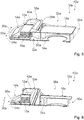
- the fluid flow 56a is provided for the cooling body 12a (cf. Figure 8 ).
- the fluid flow 56a in particular through the fan unit 18a, is blown laterally into the cooling channel 16a with respect to the longitudinal direction 20a of the cooling channel 16a.
- the fluid stream 56a in particular blown into the cooling channel 16a by the fan unit 18a, flows, in particular in at least one cooling step 66a, through the cooling channel 16a, in particular in the form of the partial fluid streams 58a and advantageously in two opposite directions, and in particular cools the electronic unit 14a at least partially by means of the heat sink 12a.
- the exhaust air unit 38a removes the fluid flow 56a exiting from the cooling channel 16a.
Landscapes
- Engineering & Computer Science (AREA)
- Chemical & Material Sciences (AREA)
- Combustion & Propulsion (AREA)
- Mechanical Engineering (AREA)
- General Engineering & Computer Science (AREA)
- Physics & Mathematics (AREA)
- Electromagnetism (AREA)
- Cooling Or The Like Of Electrical Apparatus (AREA)
Abstract
Description
- Die Erfindung betrifft eine Haushaltsgerätevorrichtung nach dem Oberbegriff des Anspruchs 1 und ein Verfahren zu einem Betrieb einer Haushaltsgerätevorrichtung nach dem Oberbegriff des Anspruchs 13.
- Aus dem Stand der Technik ist bereits ein als Kochfeld ausgebildetes Haushaltsgerät bekannt, welches einen Kühlkörper aufweist. Der Kühlkörper weist einen Kühlkanal auf und kühlt in einem Betriebszustand mittels des Kühlkanals eine Elektronikeinheit. Das Kochfeld weist eine Gebläseeinheit auf, welche in einem Betriebszustand einen Fluidstrom für den Kühlkörper bereitstellt. Die Gebläseeinheit ist bezüglich einer Längsrichtung des Kühlkanals an einem ersten Ende des Kühlkanals angeordnet und bläst den Fluidstrom parallel zu der Längsrichtung des Kühlkanals in den Kühlkanal ein. Der Fluidstrom strömt in der Längsrichtung des Kühlkanals von dem ersten Ende des Kühlkanals zu einem dem ersten Ende in der Längsrichtung entgegengesetzten zweiten Ende des Kühlkanals durch den Kühlkanal hindurch.
- Die Aufgabe der Erfindung besteht insbesondere, aber nicht beschränkt darauf, darin, eine gattungsgemäße Vorrichtung mit verbesserten Eigenschaften hinsichtlich einer Kühlung bereitzustellen. Die Aufgabe wird erfindungsgemäß durch die Merkmale der Ansprüche 1 und 13 gelöst, während vorteilhafte Ausgestaltungen und Weiterbildungen der Erfindung den Unteransprüchen entnommen werden können.
- Die Erfindung geht aus von einer Haushaltsgerätevorrichtung, insbesondere von einer Gargerätevorrichtung, vorteilhaft von einer Induktionsgargerätevorrichtung, besonders vorteilhaft von einer Kochfeldvorrichtung und vorzugsweise von einer Induktionskochfeldvorrichtung, mit zumindest einem Kühlkörper, welcher insbesondere zu einer wenigstens teilweisen Kühlung zumindest einer Elektronikeinheit vorgesehen ist und welcher zumindest einen Kühlkanal aufweist, und mit zumindest einer Gebläseeinheit, welche in einem Betriebszustand zumindest einen Fluidstrom für den Kühlkörper bereitstellt.
- Es wird vorgeschlagen, dass die Gebläseeinheit bezüglich einer Längsrichtung des Kühlkanals seitlich einen Fluidstrom in den Kühlkanal einbläst.
- Durch eine derartige Ausgestaltung kann insbesondere eine optimierte Kühlung, insbesondere der Elektronikeinheit, erreicht werden. Insbesondere in einem Vergleich zu bekannten Lösungen, können Kühlungseigenschaften insbesondere bei maximal gleichbleibenden und vorteilhaft geringeren Kosten optimiert und/oder verbessert werden, wodurch insbesondere ein hoher Bedienkomfort ermöglicht werden kann.
- Es kann insbesondere eine vorteilhafte Konstruktion erreicht werden. Insbesondere durch den seitlich zu der Längsrichtung des Kühlkanals ausgerichteten Fluidstrom, kann, insbesondere zusätzlich zu einer Kühlung der Elektronikeinheit mittels des Kühlkanals, vorteilhaft eine direkte Kühlung der Elektronikeinheit mittels des Fluidstroms ermöglicht werden, da dieser insbesondere wenigstens teilweise in Richtung der Elektronikeinheit ausgerichtet sein könnte, wodurch insbesondere besonders vorteilhafte Kühlungseigenschaften bereitgestellt werden können. Beispielsweise könnten aufgrund verbesserter Kühlungseigenschaften teure Elektronikkomponenten der Elektronikeinheit durch billigere ersetzt werden, wodurch beispielsweise eine kostengünstige Ausgestaltung erzielt werden könnte.
- Unter einer "Haushaltsgerätevorrichtung", insbesondere unter einer "Gargerätevorrichtung", vorteilhaft unter einer "Induktionsgargerätevorrichtung", besonders vorteilhaft unter einer "Kochfeldvorrichtung" und vorzugsweise unter einer "Induktionskochfeldvorrichtung", soll insbesondere zumindest ein Teil, insbesondere eine Unterbaugruppe, eines Haushaltsgeräts, insbesondere eines Gargeräts, vorteilhaft eines Induktionsgargeräts, besonders vorteilhaft eines Kochfelds und vorzugsweise eines Induktionskochfelds, verstanden werden. Beispielsweise könnte ein die Haushaltsgerätevorrichtung aufweisendes Haushaltsgerät ein Kältegerät sein, wie beispielsweise eine Kühltruhe und vorteilhaft ein Kühl- und/oder Gefrierschrank. Ein die Haushaltsgerätevorrichtung aufweisendes Haushaltsgerät könnte, insbesondere alternativ oder zusätzlich, beispielsweise ein Reinigungsgerät sein, wie beispielsweise eine Spülmaschine und/oder eine Waschmaschine und/oder ein Trockner. Vorteilhaft handelt es sich bei einem die Haushaltsgerätevorrichtung aufweisenden Haushaltsgerät um ein Gargerät und vorteilhaft um ein Induktionsgargerät. Ein als Gargerät ausgebildetes Haushaltsgerät könnte beispielsweise ein Ofen und/oder eine Mikrowelle und/oder ein Grillgerät und/oder ein Dampfgargerät sein. Der Ofen könnte beispielsweise ein Backofen, insbesondere ein Induktionsbackofen, und/oder ein Herd, insbesondere ein Induktionsherd, sein. Vorteilhaft ist ein als Gargerät ausgebildetes Haushaltsgerät ein Kochfeld und vorzugsweise ein Induktionskochfeld.
- Unter einem "Kühlkörper" soll insbesondere eine Einheit verstanden werden, welche in einem Betriebszustand zumindest eine zu kühlende Baueinheit vor einer Überhitzung schützt und/oder von zumindest einer zu kühlenden Baueinheit, insbesondere verstärkt, Wärme abführt. Der Kühlkörper weist insbesondere zumindest eine Kühlrippe und/oder zumindest eine Kühllamelle, vorteilhaft mehrere Kühlrippen und/oder mehrere Kühllamellen, auf, welche in einem Betriebszustand insbesondere von dem Fluidstrom durchströmt werden. Insbesondere stellt der Kühlkörper, insbesondere mittels der Kühlrippe und/oder der Kühllamelle, vorteilhaft mittels der Kühlrippen und/oder der Kühllamellen, eine vergrößerte Oberfläche bereit, insbesondere um eine Kühlleistung des Kühlkörpers zu verbessern und/oder um eine verstärkte Wärmeabfuhr der zu kühlenden Baueinheit zu ermöglichen. Der Kühlkörper hält in einem Betriebszustand insbesondere eine Temperatur der zu kühlenden Baueinheit insbesondere wenigstens im Wesentlichen konstant und vorteilhaft konstant. Insbesondere weist der Kühlkörper zumindest eine Kühloberfläche auf, welche in einem Betriebszustand die zu kühlende Baueinheit wenigstens teilweise berührt und insbesondere in einem Betriebszustand Energie, insbesondere in Form von Wärme, von der zu kühlenden Baueinheit aufnimmt und/oder der zu kühlenden Baueinheit Energie entzieht.
- Die zu kühlende Baueinheit könnte beispielsweise zumindest einen Wechselrichter und/oder zumindest einen Gleichrichter und/oder zumindest eine Diode und/oder zumindest eine Diodenschaltung aufweisen. Beispielsweise könnte es sich bei der zu kühlenden Baueinheit um eine Einheit handeln, welche in einem Betriebszustand zu einer, insbesondere verstärkten, Erwärmung und/oder Überhitzung neigt und/oder vorgesehen ist. Die zu kühlende Baueinheit ist insbesondere eine elektrische und/oder elektronische Einheit. Insbesondere weist die Elektronikeinheit die zu kühlende Baueinheit auf.
- Die Haushaltsgerätevorrichtung weist insbesondere zumindest eine und vorteilhaft zumindest die Elektronikeinheit auf. Die Elektronikeinheit ist insbesondere eine elektrische und/oder elektronische Einheit. Beispielsweise könnte die Elektronikeinheit in einem Betriebszustand bei zumindest einer Gerätefunktion und/oder vorteilhaft bei zumindest einer Gerätehauptfunktion zumindest mitwirken. Die Gerätefunktion und/oder die Gerätehauptfunktion könnte beispielsweise zumindest eine Kältefunktion, wie beispielsweise eine Kühlungsfunktion und/oder eine Gefrierfunktion, und/oder zumindest eine Reinigungsfunktion umfassen. Vorteilhaft könnte die Gerätefunktion und/oder die Gerätehauptfunktion zumindest eine Garfunktion und/oder zumindest eine Heizfunktion umfassen.
- Insbesondere kühlt der Kühlkörper, insbesondere mittels des Kühlkanals, in einem Betriebszustand die Kühlungseinheit. Der Kühlkörper könnte den Kühlkanal insbesondere definieren und/oder begrenzen und/oder ausbilden. Insbesondere ist der Kühlkanal als ein von dem Kühlkörper wenigstens abschnittsweise umgebener und/oder umschlossener räumlicher Bereich ausgebildet.
- Der Kühlkörper könnte vorteilhaft zumindest eine äußere Begrenzung des Kühlkanals ausbilden und/oder definieren und/oder bereitstellen. Beispielsweise könnte der Kühlkörper den Kühlkanal senkrecht zu der Längsrichtung des Kühlkanals, insbesondere wenigstens abschnittsweise und beispielsweise wenigstens im Wesentlichen, umgeben und/oder umschließen. Insbesondere umgibt und/oder umschließt der Kühlkörper den Kühlkanal in zumindest einer Querschnittsebene, welche senkrecht zu der Längsrichtung des Kühlkanals ausgerichtet ist, bezüglich zumindest eines geometrischen Mittelpunkts und/oder Schwerpunkts des Kühlkanals in der Querschnittsebene über einen Winkelbereich von mindestens 90 °, insbesondere von mindestens 180 °, vorteilhaft von mindestens 240 °, besonders vorteilhaft von mindestens 270 °, vorzugsweise von mindestens 320 ° und besonders bevorzugt von mindestens 350 °. Der Kühlkörper umgibt und/oder umschließt den Kühlkanal insbesondere in zumindest einer Querschnittsebene, welche senkrecht zu der Längsrichtung des Kühlkanals ausgerichtet ist, bezüglich zumindest eines geometrischen Mittelpunkts und/oder Schwerpunkts des Kühlkanals in der Querschnittsebene von mindestens zwei Seiten, vorteilhaft von mindestens drei Seiten und vorzugsweise von mindestens vier Seiten.
- Beispielsweise könnte der Kühlkörper den Kühlkanal in zumindest zwei in Längsrichtung des Kühlkanals zueinander beabstandeten Querschnittsebenen über verschiedene Winkelbereiche und/oder über eine verschiedene Anzahl an Seiten umgeben und/oder umschließen. Der Kühlkörper könnte den Kühlkanal in zumindest einer ersten Querschnittsebene beispielsweise über einen Winkelbereich von wenigstens im Wesentlichen 270 ° und/oder von drei Seiten umgeben und/oder umschließen und insbesondere in zumindest einer zu der ersten Querschnittsebene in der Längsrichtung des Kühlkanals beabstandeten zweiten Querschnittsebene beispielsweise über einen Winkelbereich von wenigstens im Wesentlichen 360 ° und/oder von vier Seiten umgeben und/oder umschließen.
- Unter einem "Kühlkanal" soll insbesondere ein räumlicher Bereich verstanden werden, welcher in einem Betriebszustand zumindest einen und vorteilhaft zumindest den Fluidstrom, insbesondere wenigstens abschnittsweise, in der Längsrichtung transportiert. Beispielsweise könnte der Kühlkanal senkrecht zu der Längsrichtung des Kühlkanals eine, insbesondere wenigstens abschnittsweise und beispielsweise wenigstens im Wesentlichen, geschlossene Gestalt aufweisen.
- Beispielsweise könnte der Kühlkörper wenigstens zu einem Großteil aus zumindest einem Metall, wie beispielsweise Aluminium, bestehen. Unter "wenigstens zu einem Großteil" soll insbesondere zu einem Anteil, insbesondere einem Massenanteil und/oder einem Volumenanteil, von mindestens 70 %, insbesondere von mindestens 80 %, vorteilhaft von mindestens 90 % und vorzugsweise von mindestens 95 % verstanden werden.
- Insbesondere soll unter einer "Längsrichtung des Kühlkanals" eine Längserstreckungsrichtung des Kühlkanals und/oder eine Richtung verstanden werden, entlang welcher sich zumindest ein Kanal des Kühlkörpers erstreckt. Unter einer "Längserstreckungsrichtung" eines Objekts soll insbesondere eine Richtung verstanden werden, welche parallel zu einer längsten Seite eines kleinsten gedachten geometrischen Quaders ausgerichtet ist, welcher das Objekt gerade noch vollständig umschließt. Unter einer "Erstreckung" eines Objekts soll insbesondere ein maximaler Abstand zweier Punkte einer senkrechten Projektion des Objekts auf eine Ebene verstanden werden. Unter einer "Längsrichtung" eines Objekts soll insbesondere eine Richtung verstanden werden, welche parallel zu einer längsten Seite eines kleinsten gedachten geometrischen Quaders ausgerichtet ist, welcher das Objekt gerade noch vollständig umschließt. Insbesondere ist die Längsrichtung des Kühlkanals durch die Längsrichtung der Kühlkanaleinheit definiert.
- Die Längsrichtung des Kühlkanals und die Längsrichtung der Kühlkanaleinheit sind insbesondere identisch.
- Der Kühlkörper könnte beispielsweise genau einen und vorteilhaft genau den Kühlkanal definieren und/oder begrenzen und/oder ausbilden. Beispielsweise alternativ, könnte der Kühlkörper insbesondere zumindest zwei, vorteilhaft zumindest drei, besonders vorteilhaft zumindest vier, vorzugsweise zumindest fünf und besonders bevorzugt mehrere Kühlkanäle definieren und/oder begrenzen und/oder ausbilden, welche beispielsweise parallel zueinander angeordnet und/oder geschaltet sein könnten und welche insbesondere gemeinsam zu einer wenigstens abschnittsweisen Führung des Fluidstroms vorgesehen sein könnten. In einem Betriebszustand könnte beispielsweise jeder der Kühlkanäle zumindest einen Anteil des Fluidstroms führen, wobei eine Summe der einzelnen Anteile eines jeden Kühlkanals insbesondere dem Fluidstrom entsprechen könnte. Vorteilhaft könnten zumindest zwei der, besonders vorteilhaft wenigstens ein Großteil der und vorzugsweise alle der Kühlkanäle übereinander angeordnet sein.
- Unter einer "Gebläseeinheit" soll insbesondere eine Einheit verstanden werden, welche zumindest einen Ventilator aufweist und welche mittels des Ventilators, vorteilhaft zum Zweck einer Bereitstellung des Fluidstroms, in einem Betriebszustand durch eine rotatorische Bewegung zumindest eines Laufrads des Ventilators ein gasförmiges Medium, insbesondere Luft, fördert und/oder verdichtet. Die Gebläseeinheit weist insbesondere zumindest einen Antriebsmotor auf, welcher in einem Betriebszustand zumindest eine Antriebsenergie zu einem Antrieb des Ventilators bereitstellt. Der Antriebsmotor könnte beispielsweise zumindest einen Elektromotor aufweisen und/oder als Elektromotor ausgebildet sein.
- Der Fluidstrom ist insbesondere als ein Kühlluftstrom ausgebildet und weist insbesondere eine Strömungsgeschwindigkeit größer als Null auf. Vorteilhaft handelt es sich bei dem Fluidstrom um einen Strom zumindest eines Fluids und vorteilhaft zumindest eines Gases, insbesondere Luft, in welchem beispielsweise Flüssigpartikel gelöst sein könnten.
- Unter der Wendung, dass die Gebläseeinheit in einem Betriebszustand zumindest einen Fluidstrom "für" den Kühlkörper bereitstellt, soll insbesondere verstanden werden, dass die Gebläseeinheit in einem Betriebszustand den Fluidstrom zum Zweck bereitstellt, um den Fluidstrom dem Kühlkörper zuzuführen. Insbesondere bläst die Gebläseeinheit in einem Betriebszustand den Fluidstrom in Richtung des Kühlkörpers und/oder in Richtung zumindest einer Fluidstromführungseinheit aus, welche, insbesondere wenigstens abschnittsweise, insbesondere zu einem Transport des Fluidstroms zu dem Kühlkörper vorgesehen ist und welche insbesondere den Fluidstrom in einem Betriebszustand, insbesondere wenigstens abschnittsweise, zu dem Kühlkörper transportiert.
- Insbesondere weist der Kühlkörper zumindest einen Eintrittsbereich auf, über welchen der Fluidstrom insbesondere in den Kühlkanal und/oder in den Kühlkörper eintritt. Der Eintrittsbereich ist insbesondere in einem Seitenbereich des Kühlkörpers angeordnet, welcher sich parallel zu der Längsrichtung des Kühlkörpers und/oder des Kühlkanals erstreckt, und zwar insbesondere wenigstens zu einem Großteil über eine gesamte Erstreckung des Kühlkörpers und/oder des Kühlkanals in der Längsrichtung. In einem Betriebszustand bläst die Gebläseeinheit insbesondere den Fluidstrom durch den Eintrittsbereich hindurch in den Kühlkanal und/oder in den Kühlkörper ein.
- Unter der Wendung, dass die Gebläseeinheit bezüglich einer Längsrichtung des Kühlkanals "seitlich" einen Fluidstrom in den Kühlkanal einbläst, soll insbesondere verstanden werden, dass die Gebläseeinheit in einem Betriebszustand den Fluidstrom, insbesondere in einer Einblasrichtung, schräg relativ zu der Längsrichtung in den Kühlkanal und/oder in den Kühlkörper einbläst. Insbesondere ist eine Einblasrichtung des Fluidstroms schräg relativ zu der Längsrichtung ausgerichtet. Unter einer "schräg" relativ zu der Längsrichtung ausgerichteten Einblasrichtung soll insbesondere eine Richtung verstanden werden, welche die Einblasrichtung mit der Längsrichtung einen kleinsten Winkel von ausschließlich 0 ° bis ausschließlich 180 ° einschließt. Beispielsweise könnten die Einblasrichtung und/oder der Fluidstrom und die Längsrichtung einen kleinsten Winkel von mindestens 5 °, insbesondere von mindestens 10°, vorteilhaft von mindestens 20°, besonders vorteilhaft von mindestens 30 °, vorzugsweise von mindestens 40 ° und besonders bevorzugt von mindestens 50 ° einschließen. Die Einblasrichtung und/oder der Fluidstrom und die Längsrichtung könnten beispielsweise einen kleinsten Winkel von maximal 175°, insbesondere von maximal 170°, vorteilhaft von maximal 160°, besonders vorteilhaft von maximal 150°, vorzugsweise von maximal 140 ° und besonders bevorzugt von maximal 130 ° einschließen.
- Unter "vorgesehen" soll insbesondere speziell programmiert, ausgelegt und/oder ausgestattet verstanden werden. Darunter, dass ein Objekt zu einer bestimmten Funktion vorgesehen ist, soll insbesondere verstanden werden, dass das Objekt diese bestimmte Funktion in zumindest einem Anwendungs- und/oder Betriebszustand erfüllt und/oder ausführt.
- Beispielsweise könnte die Gebläseeinheit den Fluidstrom in einem Betriebszustand in der Längsrichtung in zumindest einem Längsendbereich des Kühlkanals und/oder des Kühlkörpers in den Kühlkanal und/oder in den Kühlkörper einblasen. Der Längsendbereich des Kühlkanals und/oder des Kühlkörpers könnte insbesondere ein Bereich sein, welcher in einem Nahbereich zumindest eines Längsendes des Kühlkanals und/oder des Kühlkörpers angeordnet ist. Vorzugsweise bläst die Gebläseeinheit bezüglich einer Längserstreckung des Kühlkanals in der Längsrichtung des Kühlkanals den Fluidstrom wenigstens im Wesentlichen mittig in den Kühlkanal ein. In einem Betriebszustand bläst die Gebläseeinheit den Fluidstrom insbesondere auf wenigstens im Wesentlichen einer Hälfte eines Abstands zwischen zwei einander in der Längsrichtung des Kühlkanals und/oder des Kühlkörpers gegenüberliegenden Längsenden des Kühlkanals und/oder des Kühlkörpers in den Kühlkanal und/oder in den Kühlkörper ein. Unter "wenigstens im Wesentlichen" soll in diesem Zusammenhang insbesondere verstanden werden, dass eine Abweichung von einem vorgegebenen Wert insbesondere maximal 25 %, vorzugsweise maximal 10 % und besonders bevorzugt maximal 5 % des vorgegebenen Werts beträgt. Beispielsweise könnte die Gebläseeinheit den Fluidstrom in einem Betriebszustand über zumindest einen Eintrittsbereich des Kühlkanals und/oder des Kühlkörpers in den Kühlkanal und/oder in den Kühlkörper einblasen, welcher von zumindest einem Längsende des Kühlkanals und/oder des Kühlkörpers, und vorteilhaft von beiden Längsenden des Kühlkanals und/oder des Kühlkörpers, einen Abstand von mindestens 20 %, insbesondere von mindestens 25 %, vorteilhaft von mindestens 30 %, besonders vorteilhaft von mindestens 30 %, vorzugsweise von mindestens 40 % und besonders bevorzugt von mindestens 45 % einer Gesamterstreckung des Kühlkanals und/oder des Kühlkörpers in der Längsrichtung beträgt. Unter einem "Längsende" eines Objekts soll insbesondere ein Ende des Objekts in einer Längsrichtung des Objekts verstanden werden. Dadurch kann insbesondere eine effiziente Kühlung bereitgestellt werden. Insbesondere kann der Fluidstrom ausgehend von einem wenigstens im Wesentlichen mittig angeordneten Eintrittsbereich in zwei einander entgegengesetzte Richtungen, welche insbesondere parallel zu der Längsrichtung ausgerichtet sind, den Kühlkanal und/oder den Kühlkörper passieren, wodurch der Fluidstrom insbesondere durch einen hohen Strömungsquerschnitt strömen kann und damit insbesondere einen geringen Strömungswiderstand zu überwinden hat. Beispielsweise könnten aufgrund verbesserter Kühlungseigenschaften teure Elektronikkomponenten der Elektronikeinheit durch billigere ersetzt werden, wodurch beispielsweise eine kostengünstige Ausgestaltung erzielt werden könnte. Besonders vorteilhaft kann über eine Gesamterstreckung des Kühlkanals und/oder des Kühlkörpers eine gleichmäßige Kühlung bereitgestellt werden. Es kann insbesondere ein Aufteilen des Fluidstroms in zumindest zwei Teilfluidströme bewirkt werden, welche, insbesondere ausgehend von dem Eintrittsbereich des Kühlkanals, insbesondere in voneinander wegweisende Richtungen fließen könnten, wodurch insbesondere ein geringer Strömungswiderstand ermöglicht werden könnte. Vorteilhaft könnte eine geringe Geschwindigkeit des Laufrads des Ventilators erreicht werden, wodurch insbesondere ein geräuscharmer Betrieb erzielt werden könnte.
- Die Gebläseeinheit könnte den Fluidstrom beispielsweise relativ zu der Längsrichtung unter einem kleinsten Winkel von mindestens 55 °, insbesondere von mindestens 70 °, vorteilhaft von mindestens 65°, besonders vorteilhaft von mindestens 70°, vorzugsweise von mindestens 75 ° und besonders bevorzugt von mindestens 80 ° in den Kühlkanal und/oder in den Kühlkörper einblasen. Beispielsweise könnte die Gebläseeinheit den Fluidstrom relativ zu der Längsrichtung unter einem kleinsten Winkel von maximal 125 °, insbesondere von maximal 120 °, vorteilhaft von maximal 115°, besonders vorteilhaft von maximal 110 °, vorzugsweise von maximal 105 ° und besonders bevorzugt von maximal 100 ° in den Kühlkanal und/oder in den Kühlkörper einblasen. Vorzugsweise bläst die Gebläseeinheit bezüglich der Längsrichtung des Kühlkanals den Fluidstrom wenigstens im Wesentlichen senkrecht in den Kühlkanal ein. Der Ausdruck "wenigstens im Wesentlichen senkrecht" soll hier insbesondere eine Ausrichtung einer Richtung relativ zu einer Bezugsrichtung definieren, wobei die Richtung und die Bezugsrichtung, insbesondere in einer Projektionsebene betrachtet, einen Winkel von 90° einschließen und der Winkel eine maximale Abweichung von insbesondere maximal 8 °, vorteilhaft maximal 5° und besonders vorteilhaft maximal 2° aufweist. Dadurch können insbesondere optimierte Kühlungseigenschaften ermöglicht werden. Es könnte insbesondere eine turbulente Strömung in einem Eintrittsbereich des Kühlkanals und/oder des Kühlkörpers bewirkt werden, wodurch insbesondere ein optimierter Kälteaustausch erzielt werden könnte. Insbesondere kann, insbesondere zusätzlich zu einer Kühlung der Elektronikeinheit mittels des Kühlkanals, vorteilhaft eine direkte Kühlung der Elektronikeinheit mittels des Fluidstroms ermöglicht werden, da dieser insbesondere wenigstens teilweise in Richtung der Elektronikeinheit ausgerichtet sein könnte, wodurch insbesondere besonders vorteilhafte Kühlungseigenschaften bereitgestellt werden können.
- Weiterhin wird vorgeschlagen, dass der Kühlkanal in zumindest einem Seitenbereich, in welchem der Fluidstrom in den Kühlkanal eintritt, über einen Anteil von mindestens 20 %, insbesondere von mindestens 25 %, vorteilhaft von mindestens 30 %, besonders vorteilhaft von mindestens 35 %, vorzugsweise von mindestens 40 % und besonders bevorzugt von mindestens 50 % einer Längserstreckung des Kühlkanals wandungsfrei ausgebildet ist. Unter einer "Längserstreckung" eines Objekts soll insbesondere eine Erstreckung des Objekts entlang einer Längserstreckungsrichtung des Objekts verstanden werden. Beispielsweise könnte der Kühlkanal in dem Seitenbereich wenigstens zu einem Großteil wandungsfrei und vorteilhaft wandungsfrei ausgebildet sein. Vorteilhaft ist der Kühlkanal in zumindest einem Längsendbereich und vorteilhaft in beiden Längsendbereichen in dem Seitenbereich bewandet und/oder durch zumindest eine Wandung verschlossen. Dadurch kann insbesondere ein großer Eintrittsbereich bereitgestellt werden, wodurch insbesondere ein geringer Strömungswiderstand für den Fluidstrom und/oder optimierte Kühlungseigenschaften ermöglicht werden kann/können.
- Beispielsweise könnte der Kühlkanal genau einen Austrittsbereich aufweisen, welcher zu einem Austritt des Fluidstroms vorgesehen sein könnte und durch welchen in einem Betriebszustand der Fluidstrom insbesondere austreten könnte. Vorzugsweise weist der Kühlkanal zumindest zwei Austrittsbereiche auf, welche zu einem Austritt zumindest eines Teils des Fluidstroms vorgesehen sind. In einem Betriebszustand tritt insbesondere über jeden der Austrittsbereiche zumindest ein Teil des, insbesondere über den Eintrittsbereich in den Kühlkanal und/oder in den Kühlkörper eingetretenen, Fluidstroms aus dem Kühlkanal und/oder aus dem Kühlkörper aus. Insbesondere tritt in einem Betriebszustand insbesondere wenigstens im Wesentlichen ein gleicher Anteil und vorteilhaft ein gleicher Anteil des Fluidstroms über einen jeden der Austrittsbereiche aus dem Kühlkanal und/oder aus dem Kühlkörper aus. Dadurch kann insbesondere der Fluidstrom insbesondere durch einen hohen Strömungsquerschnitt strömen, wodurch insbesondere ein geringer Strömungswiderstand ermöglicht werden kann. Insbesondere gilt, dass je geringer ein Strömungswiderstand ist, desto geringer kann eine Geschwindigkeit des Laufrads des Ventilators sein und/oder desto höher kann ein Volumen des Fluidstroms sein. Es kann insbesondere ein geringer Druck der Gebläseeinheit erzielt werden. Insbesondere kann ein hoher Luftaustausch ermöglicht werden, wodurch insbesondere Kühlungseigenschaften optimiert werden können.
- Zudem wird vorgeschlagen, dass die Austrittsbereiche bezüglich der Längsrichtung auf zwei einander gegenüberliegenden Seiten des Kühlkanals angeordnet sind. Die Austrittsbereiche sind insbesondere in der Längsrichtung in einander gegenüberliegenden Längsendbereichen des Kühlkanals und/oder des Kühlkörpers angeordnet. Dadurch kann in der Längsrichtung insbesondere ein Durchlaufen des Fluidstroms durch den gesamten Kühlkanal und/oder den gesamten Kühlkörper erreicht werden, wodurch insbesondere eine gleichmäßige und/oder großflächige Kühlung bereitgestellt werden kann.
- Beispielsweise könnte die Gehäuseeinheit den Kühlkörper wenigstens teilweise definieren und/oder ausbilden. Vorteilhaft sind die Gehäuseeinheit und der Kühlkörper voneinander verschieden ausgebildet.
- Zudem wird vorgeschlagen, dass die Haushaltsgerätevorrichtung zumindest eine Gehäuseeinheit aufweist, innerhalb welcher der Kühlkörper, insbesondere wenigstens zu einem Großteil angeordnet und vorteilhaft angeordnet ist. Unter einer "Gehäuseeinheit" soll insbesondere eine Einheit verstanden werden, welche in einem montierten Zustand zumindest einen, insbesondere als Hohlraum ausgebildeten, Aufnahmeraum zu einer Aufnahme und/oder zu einer Lagerung zumindest des Kühlkörpers und insbesondere zumindest eines weiteren Bauteils wenigstens teilweise begrenzt und/oder definiert. Das weitere Bauteil könnte beispielsweise zumindest eine Heizeinheit und/oder zumindest eine Steuereinheit und/oder zumindest eine Versorgungseinheit und/oder zumindest eine Bedienerschnittstelle sein. Unter der Wendung, dass eine Gehäuseeinheit einen Aufnahmeraum "wenigstens teilweise" begrenzt und/oder definiert, soll insbesondere verstanden werden, dass die Gehäuseeinheit den Aufnahmeraum alleine oder gemeinsam mit zumindest einer weiteren Einheit, wie beispielsweise mit einer Haushaltsgeräteplatte, begrenzt und/oder definiert. Insbesondere begrenzen die Gehäuseeinheit und die Haushaltsgeräteplatte insbesondere gemeinsam den Aufnahmeraum wenigstens im Wesentlichen. Die Gehäuseeinheit nimmt in dem montierten Zustand insbesondere eine Gewichtskraft von Bauteilen wenigstens zu einem Großteil auf und/oder überträgt die Gewichtskraft an zumindest eine weitere Einheit, wie beispielsweise an eine Haushaltsgeräteplatte. Die Haushaltsgerätevorrichtung weist insbesondere zumindest eine und vorteilhaft zumindest die Haushaltsgeräteplatte auf. Vorteilhaft ist die Gehäuseeinheit als eine Außengehäuseeinheit ausgebildet und definiert insbesondere gemeinsam mit der Haushaltsgeräteplatte ein Haushaltsgeräteaußengehäuse wenigstens im Wesentlichen. Dadurch kann der Kühlkörper insbesondere besonders sicher und/oder geschützt angeordnet werden, wodurch insbesondere eine langlebige Ausgestaltung erzielt werden kann.
- Beispielsweise könnte die Haushaltsgerätevorrichtung, insbesondere zusätzlich zu der Gehäuseeinheit, zumindest eine Zuführungseinheit aufweisen, welche insbesondere wenigstens zu einem Großteil innerhalb der Gehäuseeinheit angeordnet sein könnte und welche insbesondere zumindest einen Zuführungskanal aufweisen könnte, der die Gebläseeinheit und den Kühlkanal fluidtechnisch miteinander verbinden könnte. Vorzugsweise weist die Gehäuseeinheit zumindest einen Zuführungskanal auf, welcher die Gebläseeinheit und den Kühlkanal fluidtechnisch miteinander verbindet. Insbesondere strömt in einem Betriebszustand der Fluidstrom von der Gebläseeinheit über den Zuführungskanal zu dem Kühlkanal. Der Fluidstrom passiert insbesondere bei seinem Weg von der Gebläseeinheit zu dem Kühlkanal den Zuführungskanal. Vorteilhaft ist der Zuführungskanal fluidtechnisch, insbesondere direkt, an die Gebläseeinheit und/oder, insbesondere direkt, an den Kühlkanal angebunden. Insbesondere ist der Zuführungskanal einstückig mit der Gehäuseeinheit ausgebildet. Unter "einstückig" soll insbesondere zumindest stoffschlüssig verbunden verstanden werden, beispielsweise durch einen Schweißprozess, einen Klebeprozess, einen Anspritzprozess und/oder einen anderen, dem Fachmann als sinnvoll erscheinenden Prozess, und/oder vorteilhaft in einem Stück geformt verstanden werden, wie beispielsweise durch eine Herstellung aus einem Guss und/oder durch eine Herstellung in einem Ein- oder Mehrkomponentenspritzverfahren und vorteilhaft aus einem einzelnen Rohling. Dadurch kann insbesondere eine geringe Bauteilevielfalt und/oder eine geringe Lagerhaltung erzielt werden, wodurch insbesondere geringe Kosten und/oder eine einfache und/oder schnelle Montage erreicht werden kann/können.
- Bei einer senkrechten Betrachtung auf eine Haupterstreckungsebene zumindest eines Gehäusebodens der Gehäuseeinheit könnte die Gebläseeinheit, insbesondere wenigstens teilweise, beispielsweise in einem frontseitigen Bereich der Gehäuseeinheit und/oder in einem einem Bediener zugewandten Bereich der Gehäuseeinheit angeordnet sein. Beispielsweise alternativ oder zusätzlich, könnte die Gebläseeinheit bei einer senkrechten Betrachtung auf eine Haupterstreckungsebene zumindest eines Gehäusebodens der Gehäuseeinheit beispielsweise in der Längsrichtung neben dem Kühlkörper angeordnet sein. Vorzugsweise ist die Gebläseeinheit bei einer senkrechten Betrachtung auf eine Haupterstreckungsebene zumindest eines Gehäusebodens der Gehäuseeinheit in einem rückwärtigen Bereich der Gehäuseeinheit angeordnet. Unter einer "Haupterstreckungsebene" eines Objekts soll insbesondere eine Ebene verstanden werden, welche parallel zu einer größten Seitenfläche eines kleinsten gedachten geometrischen Quaders ist, welcher das Objekt gerade noch vollständig umschließt, und insbesondere durch den Mittelpunkt des Quaders verläuft. Der Gehäuseboden der Gehäuseeinheit ist insbesondere ein Bereich der Gehäuseeinheit, welcher in einer Einbaulage einen minimalen Abstand zu einem Untergrund aufweist. Der Untergrund könnte beispielsweise ein Boden und/oder ein Fußboden und/oder eine Aufstellfläche sein. Beispielsweise könnte der Gehäuseboden plattenartig ausgebildet sein. Der Gehäuseboden könnte den Aufnahmeraum insbesondere in einer Einbaulage nach unten hin und/oder in Richtung des Untergrunds begrenzen. Insbesondere könnte der Gehäuseboden ein dem Untergrund nächstgelegener Bereich zumindest eines die Haushaltsgerätevorrichtung aufweisenden Haushaltsgeräts sein. Unter einem "rückwärtigen" Bereich der Gehäuseeinheit soll insbesondere ein Bereich verstanden werden, welcher in einer Einbaulage und bei einer senkrechten Betrachtung auf eine Haupterstreckungsebene zumindest eines Gehäusebodens der Gehäuseeinheit auf einer einem Bediener abgewandten Seite der Gehäuseeinheit angeordnet ist, und zwar insbesondere in einer parallel zu der Haupterstreckungsebene ausgerichteten Tiefenrichtung. Dadurch kann insbesondere ein hoher Bedienkomfort ermöglicht werden, da insbesondere ein großer Abstand der Gebläseeinheit zu einem Bediener und damit insbesondere ein für den Bediener geräuscharmer Betrieb ermöglicht werden kann. Es kann insbesondere ein großer zur Verfügung stehender Platz in einem Frontbereich erzielt werden, wodurch beispielsweise größere Bauteile, wie beispielsweise größere Leiterplatten, in dem Frontbereich angeordnet und damit Raum für Neuentwicklungen geschaffen werden könnte/könnten.
- Ferner wird vorgeschlagen, dass die Haushaltsgerätevorrichtung zumindest eine Ablufteinheit aufweist, welche zumindest einen Abluftkanal aufweist und welche über den Abluftkanal zu einer Abführung zumindest eines und insbesondere zumindest des aus dem Kühlkanal austretenden Fluidstroms vorgesehen ist. Beispielsweise könnte die Ablufteinheit genau einen und insbesondere genau den Abluftkanal aufweisen und über den Abluftkanal zu einer Abführung des aus dem Kühlkanal austretenden Fluidstroms vorgesehen sein. In einem Betriebszustand führt die Ablufteinheit über den Abluftkanal insbesondere den aus dem Kühlkanal austretenden Fluidstrom ab. Der Abluftkanal ist vorteilhaft in der Längsrichtung an zumindest einem Längsendbereich des Kühlkanals und/oder des Kühlkörpers angeordnet und insbesondere fluidtechnisch, insbesondere direkt, mit zumindest einem Austrittsbereich verbunden. Vorzugsweise weist die Ablufteinheit zumindest zwei und insbesondere genau zwei Abluftkanäle auf und ist über die Abluftkanäle zu einer Abführung des aus dem Kühlkanal austretenden Fluidstroms vorgesehen. In einem Betriebszustand führt die Ablufteinheit über die Abluftkanäle insbesondere den aus dem Kühlkanal austretenden Fluidstrom ab. Vorteilhaft sind die Abluftkanäle in der Längsrichtung an den Längsendbereichen des Kühlkanals und/oder des Kühlkörpers angeordnet. Die Abluftkanäle sind vorteilhaft in der Längsrichtung an den Längsendbereichen des Kühlkanals und/oder des Kühlkörpers angeordnet und insbesondere fluidtechnisch, insbesondere direkt, jeweils mit einem der Austrittsbereiche verbunden. Dadurch kann insbesondere der Fluidstrom auf konstruktiv einfache Art und Weise gezielt abgeführt werden, wodurch insbesondere eine vorteilhafte Konstruktion bereitgestellt werden kann.
- Die Gehäuseeinheit und die Ablufteinheit könnten beispielsweise voneinander verschieden sein und/oder separate Baueinheiten sein. Beispielsweise könnte die Ablufteinheit in einem Betriebszustand wenigstens zu einem Großteil innerhalb der Gehäuseeinheit angeordnet sein. Vorzugsweise definiert die Gehäuseeinheit die Ablufteinheit insbesondere wenigstens teilweise und vorteilhaft wenigstens zu einem Großteil. Die Gehäuseeinheit bildet insbesondere die Ablufteinheit insbesondere wenigstens teilweise und vorteilhaft wenigstens zu einem Großteil aus. Insbesondere sind die Gehäuseeinheit und die Ablufteinheit einstückig ausgebildet. Dadurch kann insbesondere eine geringe Lagerhaltung und/oder eine geringe Bauteilevielfalt erreicht werden, wodurch insbesondere geringe Kosten erzielt werden können. Insbesondere kann eine besonders hohe Stabilität erreicht werden, wodurch insbesondere eine langlebige Ausgestaltung bereitgestellt werden kann.
- Eine besonders vorteilhafte Kühlung kann insbesondere erreicht werden durch ein Haushaltsgerät, insbesondere durch ein Gargerät, vorteilhaft durch ein Induktionsgargerät, besonders vorteilhaft durch ein Kochfeld und vorzugsweise durch ein Induktionskochfeld, mit zumindest einer erfindungsgemäßen Haushaltsgerätevorrichtung, insbesondere mit zumindest einer Gargerätevorrichtung, vorteilhaft mit zumindest einer Induktionsgargerätevorrichtung, besonders vorteilhaft mit zumindest einer Kochfeldvorrichtung und vorzugsweise mit zumindest einer Induktionskochfeldvorrichtung.
- Vorteilhafte Kühlungseigenschaften können insbesondere weiter verbessert werden durch ein Verfahren zu einem Betrieb einer erfindungsgemäßen Haushaltsgerätevorrichtung, insbesondere einer Gargerätevorrichtung, vorteilhaft einer Induktionsgargerätevorrichtung, besonders vorteilhaft einer Kochfeldvorrichtung und vorzugsweise einer Induktionskochfeldvorrichtung, mit zumindest einem Kühlkörper, welcher insbesondere zu einer Kühlung zumindest einer Elektronikeinheit vorgesehen ist und welcher zumindest einen Kühlkanal aufweist, wobei in einem Betriebszustand zumindest ein Fluidstrom für den Kühlkörper bereitgestellt wird, und wobei ein Fluidstrom bezüglich einer Längsrichtung des Kühlkanals seitlich in den Kühlkanal eingeblasen wird.
- Die Haushaltsgerätevorrichtung soll hierbei nicht auf die oben beschriebene Anwendung und Ausführungsform beschränkt sein. Insbesondere kann die Haushaltsgerätevorrichtung zu einer Erfüllung einer hierin beschriebenen Funktionsweise eine von einer hierin genannten Anzahl von einzelnen Elementen, Bauteilen und Einheiten abweichende Anzahl aufweisen.
- Weitere Vorteile ergeben sich aus der folgenden Zeichnungsbeschreibung. In der Zeichnung sind Ausführungsbeispiele der Erfindung dargestellt. Die Zeichnung, die Beschreibung und die Ansprüche enthalten zahlreiche Merkmale in Kombination. Der Fachmann wird die Merkmale zweckmäßigerweise auch einzeln betrachten und zu sinnvollen weiteren Kombinationen zusammenfassen.
- Es zeigen:
- Fig. 1
- ein Haushaltsgerät mit einer Haushaltsgerätevorrichtung in einer schematischen Draufsicht,
- Fig. 2
- einen Ausschnitt der Haushaltsgerätevorrichtung in einer schematischen Draufsicht,
- Fig. 3
- einen Ausschnitt der Haushaltsgerätevorrichtung in einer schematischen perspektivischen Darstellung,
- Fig. 4
- einen Schnitt entlang der Linie IV-IV aus
Figur 3 in einer schematischen Schnittdarstellung, - Fig. 5
- einen Schnitt entlang der Linie V-V aus
Figur 3 in einer schematischen Schnittdarstellung, - Fig. 6
- einen Schnitt entlang der Linie VI-VI aus
Figur 3 in einer schematischen Schnittdarstellung, - Fig. 7
- den Ausschnitt der Haushaltsgerätevorrichtung aus
Figur 2 in einem Verfahrensschritt in einer schematischen Draufsicht und - Fig. 8
- ein Diagramm eines Verfahrens zu einem Betrieb der Haushaltsgerätevorrichtung in einer schematischen Darstellung.
-
Figur 1 zeigt beispielhaft ein Haushaltsgerät 42a. Das Haushaltsgerät 42a könnte beispielsweise als ein Kältegerät, wie beispielsweise als eine Kühltruhe und/oder als eine Gefriertruhe und/oder als ein Kühlschrank und/oder als ein Gefrierschrank und/oder als ein Kühl-Gefrier-Kombigerät, ausgebildet sein. Beispielsweise alternativ oder zusätzlich, könnte das Haushaltsgerät 42a beispielsweise als ein Reinigungsgerät, wie beispielsweise als eine Waschmaschine und/oder als ein Trockner und/oder als eine Spülmaschine ausgebildet sein. - Vorteilhaft ist das Haushaltsgerät 42a als ein Gargerät und besonders vorteilhaft als ein Induktionsgargerät ausgebildet. Beispielsweise könnte das Haushaltsgerät 42a als ein Ofen, insbesondere als ein Induktionsofen, und/oder als ein Grillgerät und/oder als eine Mikrowelle ausgebildet sein. Der Ofen könnte beispielsweise ein Backofen, insbesondere ein Induktionsbackofen, und/oder ein Herd, insbesondere ein Induktionsherd, sein. Im vorliegenden Ausführungsbeispiel ist das Haushaltsgerät 42a insbesondere als ein Kochfeld und vorteilhaft als ein Induktionskochfeld ausgebildet.
- Das Haushaltsgerät 42a weist insbesondere zumindest eine und vorteilhaft genau eine Haushaltsgerätevorrichtung 10a auf. Die Haushaltsgerätevorrichtung 10a ist im vorliegenden Ausführungsbeispiel insbesondere als eine Gargerätevorrichtung, insbesondere als eine Induktionsgargerätevorrichtung, ausgebildet. Die Haushaltsgerätevorrichtung 10a ist insbesondere als eine Kochfeldvorrichtung und vorteilhaft als eine Induktionskochfeldvorrichtung ausgebildet.
- Die Haushaltsgerätevorrichtung 10a weist insbesondere zumindest eine und beispielsweise genau eine Haushaltsgeräteplatte 44a auf. In einem Betriebszustand bildet die Haushaltsgeräteplatte 44a insbesondere einen Teil eines Geräteaußengehäuses, insbesondere des Haushaltsgeräts 42a, aus. Die Haushaltsgeräteplatte 44a bildet in einer Einbaulage insbesondere einen einem Bediener zugewandten Teil des Geräteaußengehäuses aus.
- Beispielsweise könnte die Haushaltsgeräteplatte 44a als Frontplatte und/oder Deckplatte des Geräteaußengehäuses, insbesondere eines als Ofen und/oder als Kältegerät und/oder als Reinigungsgerät ausgebildeten Haushaltsgeräts 42a, ausgebildet sein. Die Haushaltsgeräteplatte 44a könnte beispielsweise als eine Bodenplatte zumindest eines als Garraum, insbesondere eines als Gargerät und vorteilhaft als Ofen ausgebildeten Haushaltsgeräts 42a, ausgebildet sein. Im vorliegenden Ausführungsbeispiel ist die Haushaltsgeräteplatte 44a insbesondere als eine Kochfeldplatte ausgebildet. In einem montierten Zustand ist die Haushaltsgeräteplatte 44a insbesondere zu einem Aufstellen von Gargeschirr, insbesondere zum Zweck einer Beheizung von Gargeschirr, vorgesehen (nicht dargestellt).
- Die Haushaltsgerätevorrichtung 10a weist insbesondere zumindest eine und beispielsweise genau eine Bedienerschnittstelle 46a zu einer Eingabe und/oder Auswahl von Betriebsparametern, beispielsweise einer Heizleistung und/oder einer Heizleistungsdichte und/oder einer Heizzone und/oder einer Temperatur, insbesondere einer Betriebstemperatur und/oder eines Betriebsprogramms, wie beispielsweise eines Garprogramms, auf. Die Bedienerschnittstelle 46a ist insbesondere zu einer Ausgabe eines Werts eines Betriebsparameters an einen Bediener vorgesehen. Beispielsweise könnte die Bedienerschnittstelle 46a den Wert des Betriebsparameters in einem Betriebszustand, insbesondere an einen Bediener, optisch und/oder akustisch ausgeben.
- Die Haushaltsgerätevorrichtung 10a weist insbesondere zumindest eine und beispielsweise genau eine Steuereinheit 48a auf. Die Steuereinheit 48a ist insbesondere dazu vorgesehen, in Abhängigkeit von mittels der Bedienerschnittstelle 46a eingegebener Betriebsparameter Aktionen auszuführen und/oder Einstellungen zu verändern. Insbesondere steuert und/oder regelt die Steuereinheit 48a in einem Betriebszustand zumindest eine Gerätefunktion und/oder vorteilhaft zumindest eine Gerätehauptfunktion, insbesondere des Haushaltsgeräts 42a.
- Die Haushaltsgerätevorrichtung 10a weist insbesondere zumindest eine Heizeinheit auf (nicht dargestellt). Vorteilhaft weist die Haushaltsgerätevorrichtung 10a zumindest zwei, insbesondere zumindest vier, vorteilhaft zumindest acht, besonders vorteilhaft zumindest zwölf, vorzugsweise zumindest fünfzehn und besonders bevorzugt eine Vielzahl an Heizeinheiten auf. Beispielsweise könnten die Heizeinheiten in Form eines klassischen Kochfelds angeordnet sein, bei welchem zumindest ein Teil der Heizeinheiten insbesondere separate Heizzonen ausbilden könnte. Vorteilhaft könnte zumindest ein Teil der Heizeinheiten in Form einer Matrix angeordnet sein und insbesondere zu einer flexiblen Definition und/oder Bildung von Heizzonen, insbesondere durch die Steuereinheit 48a, zusammenfassbar sein. Im Folgenden wird beispielhaft lediglich eine der Heizeinheiten beschrieben.
- In einem Betriebszustand ist die Heizeinheit insbesondere auf einer einem Bediener abgewandten Seite der Haushaltsgeräteplatte 44a angeordnet. Insbesondere ist die Heizeinheit zu einer Bereitstellung von Heizenergie vorgesehen, und zwar insbesondere in Abhängigkeit einer Ansteuerung durch die Steuereinheit 48a. In einem Betriebszustand führt die Heizeinheit insbesondere auf der Haushaltsgeräteplatte 44a aufgestelltem Gargeschirr Energie, insbesondere zum Zweck einer Beheizung des Gargeschirrs, zu. Die Heizeinheit ist vorteilhaft als Induktionsheizeinheit ausgebildet.
- Die Haushaltsgerätevorrichtung 10a weist insbesondere zumindest eine und beispielsweise genau eine Elektronikeinheit 14a auf (vgl.
Figur 2 ). Die Elektronikeinheit 14a ist zu einer, insbesondere elektrischen, Versorgung der Heizeinheit vorgesehen. In einem Betriebszustand versorgt die Elektronikeinheit 14a insbesondere die Heizeinheit, und zwar insbesondere in Abhängigkeit einer Ansteuerung durch die Steuereinheit 48a. Die Steuereinheit 48a könnte in einem Betriebszustand beispielsweise mittels der Elektronikeinheit 14a die Heizeinheit betreiben. Insbesondere könnte die Steuereinheit 48a in einem Betriebszustand mittels der Elektronikeinheit 14a einen hochfrequenten Wechselstrom zu einem Betreiben der Heizeinheit bereitstellen. - Die Elektronikeinheit 14a weist insbesondere zumindest eine Leiterplatte 50a auf. Die Leiterplatte 50a könnte beispielsweise zu einem Tragen und/oder Halten zumindest einer Elektronikkomponente der Elektronikeinheit 14a vorgesehen sein.
- Insbesondere weist die Elektronikeinheit 14a zumindest eine, insbesondere elektrische und/oder elektronische, Baueinheit auf. Beispielsweise könnte die Elektronikeinheit 14a zumindest zwei, insbesondere zumindest drei, vorteilhaft zumindest vier, besonders vorteilhaft zumindest fünf, vorzugsweise zumindest sechs und besonders bevorzugt mehrere Baueinheiten aufweisen. Im Folgenden wird lediglich eine der Baueinheiten beschrieben.
- Die Baueinheit könnte beispielsweise zumindest einen Wechselrichter und/oder zumindest einen Gleichrichter und/oder zumindest eine Diode und/oder zumindest eine Diodenschaltung aufweisen (nicht dargestellt). In einem Betriebszustand könnte die Baueinheit, insbesondere im Fall eines ungekühlten Betriebs der Baueinheit, beispielsweise ein hohes Risiko einer Überhitzung aufweisen.
- Insbesondere zum Zweck einer Kühlung wenigstens eines Teils der Elektronikeinheit 14a und vorteilhaft zumindest der Baueinheit, weist die Haushaltsgerätevorrichtung 10a insbesondere zumindest einen und beispielsweise genau einen Kühlkörper 12a auf (vgl.
Figuren 2 bis 7 ). Der Kühlkörper 12a ist insbesondere zu einer wenigstens teilweisen Kühlung der Elektronikeinheit 14a vorgesehen. In einem Betriebszustand kühlt der Kühlkörper 12a die Elektronikeinheit 14a wenigstens teilweise. Der Kühlkörper 12a kühlt in einem Betriebszustand zumindest einen Teil der Elektronikeinheit 14a, wie beispielsweise zumindest die Baueinheit, und beispielsweise zusätzlich zumindest einen weiteren Teil der Elektronikeinheit 14a, wie beispielsweise zumindest die Leiterplatte 50a. - Der Kühlkörper 12a weist insbesondere zumindest einen Kühlkanal 16a auf. Beispielsweise könnte der Kühlkörper 12a genau einen Kühlkanal 16a aufweisen. Im vorliegenden Ausführungsbeispiel weist der Kühlkanal 16a beispielhaft fünf Kühlkanäle 16a auf. Die Kühlkanäle 16a sind insbesondere parallel zueinander geschaltet. Insbesondere sind die Kühlkanäle 16a in einer Höhenrichtung 54a übereinander angeordnet. Im Folgenden wird beispielhaft lediglich einer der Kühlkanäle 16a beschrieben.
- Die Höhenrichtung 54a ist in einer Einbaulage insbesondere senkrecht zu einem Untergrund ausgerichtet (nicht dargestellt). Insbesondere ist die Höhenrichtung 54a in einem Betriebszustand senkrecht zu einer Haupterstreckungsebene der Haushaltsgeräteplatte 44a ausgerichtet.
- Der Kühlkanal 16a ist insbesondere zu einer Führung zumindest eines Fluidstroms 56a vorgesehen. In einem Betriebszustand führt die Kühlkanal 16a insbesondere zumindest einen Fluidstrom 56a. Insbesondere führt der Kühlkanal 16a den Fluidstrom 56a in einem Betriebszustand wenigstens abschnittsweise in einer Längsrichtung 20a des Kühlkanals 16a.
- Insbesondere zu einer Bereitstellung des Fluidstroms 56a für den Kühlkörper 12a, weist die Haushaltsgerätevorrichtung 10a insbesondere zumindest eine und vorteilhaft genau eine Gebläseeinheit 18a auf. Die Gebläseeinheit 18a ist zu einer Bereitstellung des Fluidstroms 56a für den Kühlkörper 12a vorgesehen. In einem Betriebszustand stellt die Gebläseeinheit 18a den Fluidstrom 56a für den Kühlkörper 12a bereit.
- Die Gebläseeinheit 18a bläst in einem Betriebszustand bezüglich der Längsrichtung 20a des Kühlkanals 16a seitlich den Fluidstrom 56a in den Kühlkanal 16a ein. Beispielsweise könnte die Gebläseeinheit 18a in einem Betriebszustand den Fluidstrom 56a bezüglich der Längsrichtung 20a des Kühlkanals 16a schräg in den Kühlkanal 16a einblasen. Vorteilhaft bläst die Gebläseeinheit 18a bezüglich der Längsrichtung 20a des Kühlkanals 16a den Fluidstrom 56a wenigstens im Wesentlichen senkrecht in den Kühlkanal 16a ein.
- Der Kühlkanal 16a weist, insbesondere zu einem Eintritt des Fluidstroms 56a, zumindest einen und vorteilhaft genau einen Eintrittsbereich 26a auf (vgl.
Figuren 2 bis 5 und7 ). - Insbesondere ist der Eintrittsbereich 26a in zumindest einem Seitenbereich 24a des Kühlkanals 16a angeordnet. Der Kühlkanal 16a weist insbesondere zumindest einen und vorteilhaft zumindest den Seitenbereich 24a auf. In dem Seitenbereich 24a tritt der Fluidstrom 56a insbesondere in den Kühlkanal 16a ein. Im vorliegenden Ausführungsbeispiel ist der Seitenbereich 24a des Kühlkanals 16a insbesondere auf einer der Gebläseeinheit 18a zugewandten Seite des Kühlkanals 16a angeordnet.
- Die Gebläseeinheit 18a bewirkt in einem Betriebszustand insbesondere durch den wenigstens im Wesentlichen senkrecht zu der Längsrichtung 20a des Kühlkanals 16a ausgerichteten Fluidstrom 56a, insbesondere in dem Eintrittsbereich 26a, eine wenigstens abschnittsweise turbulente Strömung des Fluidstroms 56a (vgl.
Figur 7 ). Insbesondere können durch die abschnittsweise turbulente Strömung des Fluidstroms 56a optimale Kühlungseigenschaften bewirkt werden. - Bezüglich einer Längserstreckung 22a des Kühlkanals 16a in der Längsrichtung 20a des Kühlkanals 16a bläst die Gebläseeinheit 18a in einem Betriebszustand insbesondere den Fluidstrom 56a wenigstens im Wesentlichen mittig in den Kühlkanal 16a ein. Insbesondere ist der Eintrittsbereich 26a des Kühlkanals 16a bezüglich der Längserstreckung 22a des Kühlkanals 16a in der Längsrichtung 20a des Kühlkanals 16a wenigstens im Wesentlichen mittig angeordnet. Die Gebläseeinheit 18a bewirkt in dem Betriebszustand, insbesondere durch den wenigstens im Wesentlichen mittig in den Kühlkanal 16a eingeblasenen Fluidstrom 56a, eine, insbesondere wenigstens im Wesentlichen gleichmäßige, Aufteilung des Fluidstroms 56a in insbesondere zumindest zwei und vorteilhaft genau zwei Teilfluidströme 58a.
- Die Teilfluidströme 58a weisen insbesondere wenigstens im Wesentlichen eine gleiche Stromstärke auf. Insbesondere bewegen sich die Teilfluidströme 58a, insbesondere ausgehend von dem Eintrittsbereich 26a des Kühlkanals 16a, entlang der Längsrichtung 20a des Kühlkanals 16a in voneinander wegweisende Richtungen und/oder in einander entgegengesetzt ausgerichtete Richtungen. In einem Betriebszustand legt insbesondere jeder der Teilfluidströme 58a wenigstens im Wesentlichen 50 % der Längserstreckung 22a des Kühlkanals 16a in der Längsrichtung 20a in dem Kühlkanal 16a zurück. Hierdurch kann insbesondere für den Fluidstrom 56a und/oder für jeden der Teilfluidströme 58a ein geringer Strömungswiderstand ermöglicht werden, wodurch insbesondere optimale Kühlungseigenschaften bereitgestellt werden können.
- Der Kühlkanal 16a ist insbesondere in dem Seitenbereich 24a, in welchem der Fluidstrom 56a in den Kühlkanal 16a eintritt, über einen Anteil von mindestens 20 % der Längserstreckung 22a des Kühlkanals 16a wandungsfrei ausgebildet. Beispielsweise könnte der Kühlkanal 16a in dem Seitenbereich 24a im vorliegenden Ausführungsbeispiel über einen Anteil von wenigstens im Wesentlichen 50 % der Längserstreckung 22a des Kühlkanals 16a wandungsfrei ausgebildet sein. Der Kühlkanal 16a könnte beispielsweise in zumindest einem und vorteilhaft in jedem, insbesondere an den Eintrittsbereich 26a in der Längsrichtung 20a anschließenden, Längsendbereich über einen Anteil von wenigstens im Wesentlichen 25 % der Längserstreckung 22a des Kühlkanals 16a bewandet ausgebildet sein.
- Der Kühlkanal 16a weist insbesondere zumindest zwei und vorteilhaft genau zwei Austrittsbereiche 28a auf. Die Austrittsbereiche 28a sind insbesondere zu einem Austritt zumindest eines Teils des Fluidstroms 56a vorgesehen. Insbesondere tritt in einem Betriebszustand über die Austrittsbereiche 28a zumindest ein Teil des Fluidstroms aus dem Kühlkanal 16a aus. In einem Betriebszustand tritt insbesondere über jeden der Austrittsbereiche 28a insbesondere wenigstens im Wesentlichen ein gleicher Anteil des Fluidstroms 56a und vorteilhaft ein gleicher Anteil des Fluidstroms 56a aus dem Kühlkanal 16a aus.
- Insbesondere bezüglich der Längsrichtung 20a sind die Austrittsbereiche 28a auf zwei einander gegenüberliegenden Seiten des Kühlkanals 16a angeordnet. Die Austrittsbereiche 28a sind insbesondere bezüglich der Längsrichtung 20a an einander gegenüberliegenden Längsendbereichen des Kühlkanals 16a angeordnet.
- Die Haushaltsgerätevorrichtung 10a weist insbesondere zumindest eine und beispielsweise genau eine Gehäuseeinheit 30a auf (vgl.
Figuren 2 bis 7 ). In einem Betriebszustand ist die Gehäuseeinheit 30a insbesondere mit der Haushaltsgeräteplatte 44a, insbesondere mechanisch, verbunden. Insbesondere sind die Gehäuseeinheit 30a und die Haushaltsgeräteplatte 44a in einem Betriebszustand aneinander befestigt. - Die Gehäuseeinheit 30a und die Haushaltsgeräteplatte 44a bilden insbesondere zumindest das Geräteaußengehäuse, insbesondere wenigstens im Wesentlichen, aus. Insbesondere begrenzen und/oder definieren die Gehäuseeinheit 30a und die Haushaltsgeräteplatte 44a zumindest einen, insbesondere als Hohlraum ausgebildeten Aufnahmeraum zu einer Aufnahme und/oder zu einer Lagerung zumindest des Kühlkörpers 12a, insbesondere wenigstens im Wesentlichen.
- In einem Betriebszustand ist der Kühlkörper 12a insbesondere wenigstens zu einem Großteil innerhalb der Gehäuseeinheit 30a angeordnet. Die Gehäuseeinheit 30a nimmt in einem Betriebszustand insbesondere eine Gewichtskraft des Kühlkörpers 12a wenigstens zu einem Großteil auf und leitet die aufgenommene Gewichtskraft insbesondere an zumindest eine weitere Einheit, wie beispielsweise die Haushaltsgeräteplatte 44a weiter. Insbesondere trägt die Gehäuseeinheit 30a in einem Betriebszustand den Kühlkörper 12a wenigstens zu einem Großteil.
- Insbesondere zusätzlich zu dem Kühlkörper 12a, ist in einem Betriebszustand insbesondere zumindest die Gebläseeinheit 18a wenigstens zu einem Großteil innerhalb der Gehäuseeinheit 30a angeordnet. Die Gebläseeinheit 18a ist insbesondere in einem Betriebszustand bei einer senkrechten Betrachtung auf eine Haupterstreckungsebene zumindest eines Gehäusebodens 34a der Gehäuseeinheit 30a in einem rückwärtigen Bereich 36a der Gehäuseeinheit 30a angeordnet. Der rückwärtige Bereich 36a der Gehäuseeinheit 30a ist insbesondere ein in einer Einbaulage einem Bediener abgewandter Bereich der Gehäuseeinheit 30a.
- Die Gehäuseeinheit 30a weist insbesondere zumindest einen und vorteilhaft genau einen Zuführungskanal 32a auf. In einem Betriebszustand verbindet der Zuführungskanal 32a insbesondere die Gebläseeinheit 18a und den Kühlkanal 16a fluidtechnisch miteinander. Der Zuführungskanal 32a stellt in einem Betriebszustand insbesondere eine fluidtechnische Verbindung zwischen der Gebläseeinheit 18a und dem Kühlkanal 16a her.
- Im vorliegenden Ausführungsbeispiel begrenzt die Gehäuseeinheit 30a den Zuführungskanal 32a insbesondere von zumindest drei Seiten. Beispielsweise begrenzt die Gehäuseeinheit 30a den Zuführungskanal 32a, insbesondere senkrecht zu der Höhenrichtung 54a, mittels des Gehäusebodens 34a wenigstens teilweise. Die Gehäuseeinheit 30a bildet insbesondere zumindest zwei und vorteilhaft genau zwei Zuführungswandungen 60a aus. In einem Betriebszustand begrenzt die Gehäuseeinheit 30a den Zuführungskanal 32a insbesondere mittels der Zuführungswandungen 60a wenigstens teilweise.
- Die Haushaltsgerätevorrichtung 10a weist insbesondere zumindest eine und beispielsweise genau eine Ablufteinheit 38a auf. Die Ablufteinheit 38a ist insbesondere zu einer Abführung zumindest eines aus dem Kühlkanal 16a austretenden Fluidstroms 56a vorgesehen. Insbesondere führt die Ablufteinheit 38a in einem Betriebszustand den aus dem Kühlkanal 16a austretenden Fluidstrom 56a insbesondere wenigstens teilweise ab, vorteilhaft wenigstens zu einem Großteil ab und vorzugsweise ab.
- Insbesondere zu der Abführung des aus dem Kühlkanal 16a austretenden Fluidstroms 56a, weist die Ablufteinheit 38a zumindest einen Abluftkanal 40a auf. Im vorliegenden Ausführungsbeispiel weist die Ablufteinheit 38a insbesondere zumindest zwei und vorteilhaft genau zwei Abluftkanäle 40a auf. Insbesondere bezüglich der Längsrichtung 20a sind die Abluftkanäle 40a, insbesondere im Anschluss, an zwei einander gegenüberliegenden Längsendbereichen des Kühlkanals 16a angeordnet. Im Folgenden wird beispielhaft lediglich einer der Abluftkanäle 40a beschrieben.
- Der Abluftkanal 40a schließt, insbesondere direkt, an einen Längsendbereich des Kühlkanals 16a an. Insbesondere ist der Abluftkanal 40a fluidtechnisch, insbesondere direkt, mit einem Längsendbereich des Kühlkanals 16a und vorteilhaft mit dem Austrittsbereich 28a des Kühlkanals 16a verbunden.
- In einem Betriebszustand führt die Ablufteinheit 38a insbesondere mittels des Abluftkanals 40a den aus dem Kühlkanal 16a austretenden Fluidstrom 56a ab. Insbesondere ist die Ablufteinheit 38a mittels des Abluftkanals 40a zu einer Abführung des aus dem Kühlkanal 16a austretenden Fluidstroms 56a vorgesehen.
- Die Gehäuseeinheit 30a bildet insbesondere die Ablufteinheit 38a und vorteilhaft den Abluftkanal 40a aus. Insbesondere definiert die Gehäuseeinheit 30a die Ablufteinheit 38a und vorteilhaft den Abluftkanal 40a, insbesondere wenigstens teilweise und vorteilhaft wenigstens zu einem Großteil. Die Gehäuseeinheit 30a und die Ablufteinheit 38a, insbesondere der Abluftkanal 40a der Ablufteinheit 38a, sind insbesondere einstückig ausgebildet.
- In einem Verfahren zu einem Betrieb der Haushaltsgerätevorrichtung 10a wird, insbesondere in zumindest einem Bereitstellungsschritt 62a, in einem Betriebszustand, vorteilhaft durch die Gebläseeinheit 18a, der Fluidstrom 56a für den Kühlkörper 12a bereitgestellt (vgl.
Figur 8 ). Insbesondere in zumindest einem Einblasschritt 64a, wird der Fluidstrom 56a, insbesondere durch die Gebläseeinheit 18a, bezüglich der Längsrichtung 20a des Kühlkanals 16a seitlich in den Kühlkanal 16a eingeblasen. - Der, insbesondere von der Gebläseeinheit 18a in den Kühlkanal 16a eingeblasene, Fluidstrom 56a fließt, insbesondere in zumindest einem Kühlungsschritt 66a, durch den Kühlkanal 16a hindurch, und zwar insbesondere in Form der Teilfluidströme 58a und vorteilhaft in zwei einander entgegengesetzt ausgerichteten Richtungen, und kühlt insbesondere mittels des Kühlkörpers 12a die Elektronikeinheit 14a wenigstens teilweise. Insbesondere in zumindest einem Abführschritt 68a, führt die Ablufteinheit 38a den aus dem Kühlkanal 16a austretenden Fluidstrom 56a ab.
-
- 10
- Haushaltsgerätevorrichtung
- 12
- Kühlkörper
- 14
- Elektronikeinheit
- 16
- Kühlkanal
- 18
- Gebläseeinheit
- 20
- Längsrichtung
- 22
- Längserstreckung
- 24
- Seitenbereich
- 26
- Eintrittsbereich
- 28
- Austrittsbereich
- 30
- Gehäuseeinheit
- 32
- Zuführungskanal
- 34
- Gehäuseboden
- 36
- Rückwärtiger Bereich
- 38
- Ablufteinheit
- 40
- Abluftkanal
- 42
- Haushaltsgerät
- 44
- Haushaltsgeräteplatte
- 46
- Bedienerschnittstelle
- 48
- Steuereinheit
- 50
- Leiterplatte
- 54
- Höhenrichtung
- 56
- Fluidstrom
- 58
- Teilfluidstrom
- 60
- Zuführungswandung
- 62
- Bereitstellungsschritt
- 64
- Einblasschritt
- 66
- Kühlungsschritt
- 68
- Abführschritt
Claims (13)
- Haushaltsgerätevorrichtung, insbesondere Gargerätevorrichtung, mit zumindest einem Kühlkörper (12a), welcher zumindest einen Kühlkanal (16a) aufweist, und mit zumindest einer Gebläseeinheit (18a), welche in einem Betriebszustand zumindest einen Fluidstrom (56a) für den Kühlkörper (12a) bereitstellt, dadurch gekennzeichnet, dass die Gebläseeinheit (18a) bezüglich einer Längsrichtung (20a) des Kühlkanals (16a) seitlich einen Fluidstrom (56a) in den Kühlkanal (16a) einbläst.
- Haushaltsgerätevorrichtung nach Anspruch 1, dadurch gekennzeichnet, dass die Gebläseeinheit (18a) bezüglich einer Längserstreckung (22a) des Kühlkanals (16a) in der Längsrichtung (20a) des Kühlkanals (16a) den Fluidstrom (56a) wenigstens im Wesentlichen mittig in den Kühlkanal (16a) einbläst.
- Haushaltsgerätevorrichtung nach Anspruch 1 oder 2, dadurch gekennzeichnet, dass die Gebläseeinheit (18a) bezüglich der Längsrichtung (20a) des Kühlkanals (16a) den Fluidstrom (56a) wenigstens im Wesentlichen senkrecht in den Kühlkanal (16a) einbläst.
- Haushaltsgerätevorrichtung nach einem der vorhergehenden Ansprüche, dadurch gekennzeichnet, dass der Kühlkanal (16a) in zumindest einem Seitenbereich (24a), in welchem der Fluidstrom (56a) in den Kühlkanal (16a) eintritt, über einen Anteil von mindestens 20 % einer Längserstreckung (22a) des Kühlkanals (16a) wandungsfrei ausgebildet ist.
- Haushaltsgerätevorrichtung nach einem der vorhergehenden Ansprüche, dadurch gekennzeichnet, dass der Kühlkanal (16a) zumindest zwei Austrittsbereiche (28a) aufweist, welche zu einem Austritt zumindest eines Teils des Fluidstroms (56a) vorgesehen sind.
- Haushaltsgerätevorrichtung nach Anspruch 5, dadurch gekennzeichnet, dass die Austrittsbereiche (28a) bezüglich der Längsrichtung (20a) auf zwei einander gegenüberliegenden Seiten des Kühlkanals (16a) angeordnet sind.
- Haushaltsgerätevorrichtung nach einem der vorhergehenden Ansprüche, gekennzeichnet durch zumindest eine Gehäuseeinheit (30a), innerhalb welcher der Kühlkörper (12a) wenigstens zu einem Großteil angeordnet ist.
- Haushaltsgerätevorrichtung nach Anspruch 7, dadurch gekennzeichnet, dass die Gehäuseeinheit (30a) zumindest einen Zuführungskanal (32a) aufweist, welcher die Gebläseeinheit (18a) und den Kühlkanal (16a) fluidtechnisch miteinander verbindet.
- Haushaltsgerätevorrichtung nach Anspruch 7 oder 8, dadurch gekennzeichnet, dass die Gebläseeinheit (18a) bei einer senkrechten Betrachtung auf eine Haupterstreckungsebene zumindest eines Gehäusebodens (34a) der Gehäuseeinheit (30a) in einem rückwärtigen Bereich (36a) der Gehäuseeinheit (30a) angeordnet ist.
- Haushaltsgerätevorrichtung nach einem der vorhergehenden Ansprüche, gekennzeichnet durch zumindest eine Ablufteinheit (38a), welche zumindest einen Abluftkanal (40a) aufweist und welche über den Abluftkanal (40a) zu einer Abführung zumindest eines aus dem Kühlkanal (16a) austretenden Fluidstroms (56a) vorgesehen ist.
- Haushaltsgerätevorrichtung nach Anspruch 10, dadurch gekennzeichnet, dass die Gehäuseeinheit (30a) die Ablufteinheit (38a) wenigstens teilweise definiert.
- Haushaltsgerät, insbesondere Gargerät, mit zumindest einer Haushaltsgerätevorrichtung (10a) nach einem der vorhergehenden Ansprüche.
- Verfahren zu einem Betrieb einer Haushaltsgerätevorrichtung (10a), insbesondere nach einem der Ansprüche 1 bis 11, mit zumindest einem Kühlkörper (12a), welcher zumindest einen Kühlkanal (16a) aufweist, wobei in einem Betriebszustand zumindest ein Fluidstrom (56a) für den Kühlkörper (12a) bereitgestellt wird, dadurch gekennzeichnet, dass ein Fluidstrom (56a) bezüglich einer Längsrichtung (20a) des Kühlkanals (16a) seitlich in den Kühlkanal (16a) eingeblasen wird.
Applications Claiming Priority (1)
| Application Number | Priority Date | Filing Date | Title |
|---|---|---|---|
| EP19382884 | 2019-10-09 |
Publications (2)
| Publication Number | Publication Date |
|---|---|
| EP3806582A1 true EP3806582A1 (de) | 2021-04-14 |
| EP3806582B1 EP3806582B1 (de) | 2024-07-03 |
Family
ID=68503017
Family Applications (1)
| Application Number | Title | Priority Date | Filing Date |
|---|---|---|---|
| EP20199653.5A Active EP3806582B1 (de) | 2019-10-09 | 2020-10-01 | Haushaltsgerätevorrichtung |
Country Status (2)
| Country | Link |
|---|---|
| EP (1) | EP3806582B1 (de) |
| ES (1) | ES2989195T3 (de) |
Citations (3)
| Publication number | Priority date | Publication date | Assignee | Title |
|---|---|---|---|---|
| JP2004158317A (ja) * | 2002-11-07 | 2004-06-03 | Matsushita Electric Ind Co Ltd | 調理器 |
| JP2008287938A (ja) * | 2007-05-15 | 2008-11-27 | Chugoku Electric Power Co Inc:The | 電磁調理器 |
| JP2009094088A (ja) * | 2009-02-02 | 2009-04-30 | Hitachi Appliances Inc | 誘導加熱調理器 |
Family Cites Families (3)
| Publication number | Priority date | Publication date | Assignee | Title |
|---|---|---|---|---|
| JP2890415B2 (ja) * | 1988-08-16 | 1999-05-17 | 松下電器産業株式会社 | 誘導加熱調理器 |
| EP2292979B1 (de) * | 2009-09-03 | 2016-10-12 | BSH Hausgeräte GmbH | Kühlvorrichtung für ein Induktionskochfeld |
| ES2748043T3 (es) * | 2012-06-28 | 2020-03-12 | Bsh Hausgeraete Gmbh | Dispositivo de aparato doméstico |
-
2020
- 2020-10-01 EP EP20199653.5A patent/EP3806582B1/de active Active
- 2020-10-01 ES ES20199653T patent/ES2989195T3/es active Active
Patent Citations (3)
| Publication number | Priority date | Publication date | Assignee | Title |
|---|---|---|---|---|
| JP2004158317A (ja) * | 2002-11-07 | 2004-06-03 | Matsushita Electric Ind Co Ltd | 調理器 |
| JP2008287938A (ja) * | 2007-05-15 | 2008-11-27 | Chugoku Electric Power Co Inc:The | 電磁調理器 |
| JP2009094088A (ja) * | 2009-02-02 | 2009-04-30 | Hitachi Appliances Inc | 誘導加熱調理器 |
Also Published As
| Publication number | Publication date |
|---|---|
| EP3806582B1 (de) | 2024-07-03 |
| ES2989195T3 (es) | 2024-11-25 |
Similar Documents
| Publication | Publication Date | Title |
|---|---|---|
| EP2909901B1 (de) | Explosionsgeschütztes gehäuse mit einem ventilator | |
| EP1340945B1 (de) | Gerät zum Behandeln und Zubereiten von Nahrungsmitteln mit gasbefeuerter Heizung | |
| EP1970635B1 (de) | Heissluft-Backofen mit Umlenkblechen | |
| EP3628932B1 (de) | Kochfeld | |
| EP2679913A2 (de) | Hausgerätevorrichtung | |
| DE19935835C5 (de) | Induktionskochfeld mit Kühlgebläse | |
| DE10048877A1 (de) | Klimagerät | |
| DE102007029178A1 (de) | Kältegerät mit Lüfteraggregat | |
| EP3806582B1 (de) | Haushaltsgerätevorrichtung | |
| EP3453974A1 (de) | Kochfeldvorrichtung | |
| EP2498574A2 (de) | Trägerplatte für einen Schaltungsträger eines Haushaltsgeräts, Anordnung mit einer derartigen Trägerplatte sowie Induktionskochfeld mit einer Anordnung | |
| EP0942235A1 (de) | Backofen mit Sauggehäuse | |
| EP3572673B1 (de) | Kochsystem | |
| EP4332476B1 (de) | Kältegerät | |
| EP3623705A1 (de) | Gargerät | |
| DE19733314A1 (de) | Dampfgarofen mit Dampfablöschung | |
| EP1431670A2 (de) | Gehäuse für ein Gargerät | |
| EP0003764A1 (de) | Doppelbackofen, insbesondere Einbaubackofen | |
| EP3784012B1 (de) | Leistungselektronik für ein flurförderzeug | |
| EP1643808B1 (de) | Ofen zur Garbehandlung von Lebensmitteln | |
| DE102009026645B4 (de) | Gargerät | |
| DE10230244A1 (de) | Gebläseeinrichtung für ein Gargerät | |
| WO2008148675A2 (de) | Backofen | |
| DE102004046437A1 (de) | Vorrichtung mit einer Gargeräteluftführungseinheit | |
| EP3144596B1 (de) | Kochfeld |
Legal Events
| Date | Code | Title | Description |
|---|---|---|---|
| PUAI | Public reference made under article 153(3) epc to a published international application that has entered the european phase |
Free format text: ORIGINAL CODE: 0009012 |
|
| STAA | Information on the status of an ep patent application or granted ep patent |
Free format text: STATUS: THE APPLICATION HAS BEEN PUBLISHED |
|
| AK | Designated contracting states |
Kind code of ref document: A1 Designated state(s): AL AT BE BG CH CY CZ DE DK EE ES FI FR GB GR HR HU IE IS IT LI LT LU LV MC MK MT NL NO PL PT RO RS SE SI SK SM TR |
|
| AX | Request for extension of the european patent |
Extension state: BA ME |
|
| STAA | Information on the status of an ep patent application or granted ep patent |
Free format text: STATUS: REQUEST FOR EXAMINATION WAS MADE |
|
| 17P | Request for examination filed |
Effective date: 20211014 |
|
| RBV | Designated contracting states (corrected) |
Designated state(s): AL AT BE BG CH CY CZ DE DK EE ES FI FR GB GR HR HU IE IS IT LI LT LU LV MC MK MT NL NO PL PT RO RS SE SI SK SM TR |
|
| STAA | Information on the status of an ep patent application or granted ep patent |
Free format text: STATUS: EXAMINATION IS IN PROGRESS |
|
| 17Q | First examination report despatched |
Effective date: 20220708 |
|
| GRAP | Despatch of communication of intention to grant a patent |
Free format text: ORIGINAL CODE: EPIDOSNIGR1 |
|
| STAA | Information on the status of an ep patent application or granted ep patent |
Free format text: STATUS: GRANT OF PATENT IS INTENDED |
|
| RIC1 | Information provided on ipc code assigned before grant |
Ipc: F24C 15/00 20060101ALI20240130BHEP Ipc: F24C 15/10 20060101ALI20240130BHEP Ipc: H05B 6/12 20060101AFI20240130BHEP |
|
| INTG | Intention to grant announced |
Effective date: 20240226 |
|
| GRAS | Grant fee paid |
Free format text: ORIGINAL CODE: EPIDOSNIGR3 |
|
| GRAA | (expected) grant |
Free format text: ORIGINAL CODE: 0009210 |
|
| STAA | Information on the status of an ep patent application or granted ep patent |
Free format text: STATUS: THE PATENT HAS BEEN GRANTED |
|
| AK | Designated contracting states |
Kind code of ref document: B1 Designated state(s): AL AT BE BG CH CY CZ DE DK EE ES FI FR GB GR HR HU IE IS IT LI LT LU LV MC MK MT NL NO PL PT RO RS SE SI SK SM TR |
|
| REG | Reference to a national code |
Ref country code: CH Ref legal event code: EP |
|
| REG | Reference to a national code |
Ref country code: DE Ref legal event code: R096 Ref document number: 502020008437 Country of ref document: DE |
|
| REG | Reference to a national code |
Ref country code: LT Ref legal event code: MG9D |
|
| REG | Reference to a national code |
Ref country code: NL Ref legal event code: MP Effective date: 20240703 |
|
| REG | Reference to a national code |
Ref country code: ES Ref legal event code: FG2A Ref document number: 2989195 Country of ref document: ES Kind code of ref document: T3 Effective date: 20241125 |
|
| PG25 | Lapsed in a contracting state [announced via postgrant information from national office to epo] |
Ref country code: PT Free format text: LAPSE BECAUSE OF FAILURE TO SUBMIT A TRANSLATION OF THE DESCRIPTION OR TO PAY THE FEE WITHIN THE PRESCRIBED TIME-LIMIT Effective date: 20241104 |
|
| PG25 | Lapsed in a contracting state [announced via postgrant information from national office to epo] |
Ref country code: NL Free format text: LAPSE BECAUSE OF FAILURE TO SUBMIT A TRANSLATION OF THE DESCRIPTION OR TO PAY THE FEE WITHIN THE PRESCRIBED TIME-LIMIT Effective date: 20240703 |
|
| PG25 | Lapsed in a contracting state [announced via postgrant information from national office to epo] |
Ref country code: PT Free format text: LAPSE BECAUSE OF FAILURE TO SUBMIT A TRANSLATION OF THE DESCRIPTION OR TO PAY THE FEE WITHIN THE PRESCRIBED TIME-LIMIT Effective date: 20241104 Ref country code: NL Free format text: LAPSE BECAUSE OF FAILURE TO SUBMIT A TRANSLATION OF THE DESCRIPTION OR TO PAY THE FEE WITHIN THE PRESCRIBED TIME-LIMIT Effective date: 20240703 |
|
| PG25 | Lapsed in a contracting state [announced via postgrant information from national office to epo] |
Ref country code: NO Free format text: LAPSE BECAUSE OF FAILURE TO SUBMIT A TRANSLATION OF THE DESCRIPTION OR TO PAY THE FEE WITHIN THE PRESCRIBED TIME-LIMIT Effective date: 20241003 |
|
| PG25 | Lapsed in a contracting state [announced via postgrant information from national office to epo] |
Ref country code: FI Free format text: LAPSE BECAUSE OF FAILURE TO SUBMIT A TRANSLATION OF THE DESCRIPTION OR TO PAY THE FEE WITHIN THE PRESCRIBED TIME-LIMIT Effective date: 20240703 Ref country code: GR Free format text: LAPSE BECAUSE OF FAILURE TO SUBMIT A TRANSLATION OF THE DESCRIPTION OR TO PAY THE FEE WITHIN THE PRESCRIBED TIME-LIMIT Effective date: 20241004 Ref country code: PL Free format text: LAPSE BECAUSE OF FAILURE TO SUBMIT A TRANSLATION OF THE DESCRIPTION OR TO PAY THE FEE WITHIN THE PRESCRIBED TIME-LIMIT Effective date: 20240703 |
|
| PG25 | Lapsed in a contracting state [announced via postgrant information from national office to epo] |
Ref country code: BG Free format text: LAPSE BECAUSE OF FAILURE TO SUBMIT A TRANSLATION OF THE DESCRIPTION OR TO PAY THE FEE WITHIN THE PRESCRIBED TIME-LIMIT Effective date: 20240703 |
|
| PG25 | Lapsed in a contracting state [announced via postgrant information from national office to epo] |
Ref country code: LV Free format text: LAPSE BECAUSE OF FAILURE TO SUBMIT A TRANSLATION OF THE DESCRIPTION OR TO PAY THE FEE WITHIN THE PRESCRIBED TIME-LIMIT Effective date: 20240703 |
|
| PG25 | Lapsed in a contracting state [announced via postgrant information from national office to epo] |
Ref country code: IS Free format text: LAPSE BECAUSE OF FAILURE TO SUBMIT A TRANSLATION OF THE DESCRIPTION OR TO PAY THE FEE WITHIN THE PRESCRIBED TIME-LIMIT Effective date: 20241103 |
|
| PG25 | Lapsed in a contracting state [announced via postgrant information from national office to epo] |
Ref country code: CZ Free format text: LAPSE BECAUSE OF FAILURE TO SUBMIT A TRANSLATION OF THE DESCRIPTION OR TO PAY THE FEE WITHIN THE PRESCRIBED TIME-LIMIT Effective date: 20240703 Ref country code: HR Free format text: LAPSE BECAUSE OF FAILURE TO SUBMIT A TRANSLATION OF THE DESCRIPTION OR TO PAY THE FEE WITHIN THE PRESCRIBED TIME-LIMIT Effective date: 20240703 |
|
| PG25 | Lapsed in a contracting state [announced via postgrant information from national office to epo] |
Ref country code: RS Free format text: LAPSE BECAUSE OF FAILURE TO SUBMIT A TRANSLATION OF THE DESCRIPTION OR TO PAY THE FEE WITHIN THE PRESCRIBED TIME-LIMIT Effective date: 20241003 |
|
| PG25 | Lapsed in a contracting state [announced via postgrant information from national office to epo] |
Ref country code: RS Free format text: LAPSE BECAUSE OF FAILURE TO SUBMIT A TRANSLATION OF THE DESCRIPTION OR TO PAY THE FEE WITHIN THE PRESCRIBED TIME-LIMIT Effective date: 20241003 Ref country code: PL Free format text: LAPSE BECAUSE OF FAILURE TO SUBMIT A TRANSLATION OF THE DESCRIPTION OR TO PAY THE FEE WITHIN THE PRESCRIBED TIME-LIMIT Effective date: 20240703 Ref country code: NO Free format text: LAPSE BECAUSE OF FAILURE TO SUBMIT A TRANSLATION OF THE DESCRIPTION OR TO PAY THE FEE WITHIN THE PRESCRIBED TIME-LIMIT Effective date: 20241003 Ref country code: LV Free format text: LAPSE BECAUSE OF FAILURE TO SUBMIT A TRANSLATION OF THE DESCRIPTION OR TO PAY THE FEE WITHIN THE PRESCRIBED TIME-LIMIT Effective date: 20240703 Ref country code: IS Free format text: LAPSE BECAUSE OF FAILURE TO SUBMIT A TRANSLATION OF THE DESCRIPTION OR TO PAY THE FEE WITHIN THE PRESCRIBED TIME-LIMIT Effective date: 20241103 Ref country code: HR Free format text: LAPSE BECAUSE OF FAILURE TO SUBMIT A TRANSLATION OF THE DESCRIPTION OR TO PAY THE FEE WITHIN THE PRESCRIBED TIME-LIMIT Effective date: 20240703 Ref country code: GR Free format text: LAPSE BECAUSE OF FAILURE TO SUBMIT A TRANSLATION OF THE DESCRIPTION OR TO PAY THE FEE WITHIN THE PRESCRIBED TIME-LIMIT Effective date: 20241004 Ref country code: FI Free format text: LAPSE BECAUSE OF FAILURE TO SUBMIT A TRANSLATION OF THE DESCRIPTION OR TO PAY THE FEE WITHIN THE PRESCRIBED TIME-LIMIT Effective date: 20240703 Ref country code: CZ Free format text: LAPSE BECAUSE OF FAILURE TO SUBMIT A TRANSLATION OF THE DESCRIPTION OR TO PAY THE FEE WITHIN THE PRESCRIBED TIME-LIMIT Effective date: 20240703 Ref country code: BG Free format text: LAPSE BECAUSE OF FAILURE TO SUBMIT A TRANSLATION OF THE DESCRIPTION OR TO PAY THE FEE WITHIN THE PRESCRIBED TIME-LIMIT Effective date: 20240703 |
|
| REG | Reference to a national code |
Ref country code: DE Ref legal event code: R097 Ref document number: 502020008437 Country of ref document: DE |
|
| PG25 | Lapsed in a contracting state [announced via postgrant information from national office to epo] |
Ref country code: DK Free format text: LAPSE BECAUSE OF FAILURE TO SUBMIT A TRANSLATION OF THE DESCRIPTION OR TO PAY THE FEE WITHIN THE PRESCRIBED TIME-LIMIT Effective date: 20240703 Ref country code: RO Free format text: LAPSE BECAUSE OF FAILURE TO SUBMIT A TRANSLATION OF THE DESCRIPTION OR TO PAY THE FEE WITHIN THE PRESCRIBED TIME-LIMIT Effective date: 20240703 Ref country code: SM Free format text: LAPSE BECAUSE OF FAILURE TO SUBMIT A TRANSLATION OF THE DESCRIPTION OR TO PAY THE FEE WITHIN THE PRESCRIBED TIME-LIMIT Effective date: 20240703 |
|
| PG25 | Lapsed in a contracting state [announced via postgrant information from national office to epo] |
Ref country code: EE Free format text: LAPSE BECAUSE OF FAILURE TO SUBMIT A TRANSLATION OF THE DESCRIPTION OR TO PAY THE FEE WITHIN THE PRESCRIBED TIME-LIMIT Effective date: 20240703 |
|
| PG25 | Lapsed in a contracting state [announced via postgrant information from national office to epo] |
Ref country code: SK Free format text: LAPSE BECAUSE OF FAILURE TO SUBMIT A TRANSLATION OF THE DESCRIPTION OR TO PAY THE FEE WITHIN THE PRESCRIBED TIME-LIMIT Effective date: 20240703 |
|
| PLBE | No opposition filed within time limit |
Free format text: ORIGINAL CODE: 0009261 |
|
| STAA | Information on the status of an ep patent application or granted ep patent |
Free format text: STATUS: NO OPPOSITION FILED WITHIN TIME LIMIT |
|
| REG | Reference to a national code |
Ref country code: CH Ref legal event code: PL |
|
| 26N | No opposition filed |
Effective date: 20250404 |
|
| PG25 | Lapsed in a contracting state [announced via postgrant information from national office to epo] |
Ref country code: MC Free format text: LAPSE BECAUSE OF FAILURE TO SUBMIT A TRANSLATION OF THE DESCRIPTION OR TO PAY THE FEE WITHIN THE PRESCRIBED TIME-LIMIT Effective date: 20240703 |
|
| PG25 | Lapsed in a contracting state [announced via postgrant information from national office to epo] |
Ref country code: LU Free format text: LAPSE BECAUSE OF NON-PAYMENT OF DUE FEES Effective date: 20241001 Ref country code: BE Free format text: LAPSE BECAUSE OF NON-PAYMENT OF DUE FEES Effective date: 20241031 |
|
| PG25 | Lapsed in a contracting state [announced via postgrant information from national office to epo] |
Ref country code: CH Free format text: LAPSE BECAUSE OF NON-PAYMENT OF DUE FEES Effective date: 20241031 |
|
| REG | Reference to a national code |
Ref country code: BE Ref legal event code: MM Effective date: 20241031 |
|
| PG25 | Lapsed in a contracting state [announced via postgrant information from national office to epo] |
Ref country code: SE Free format text: LAPSE BECAUSE OF FAILURE TO SUBMIT A TRANSLATION OF THE DESCRIPTION OR TO PAY THE FEE WITHIN THE PRESCRIBED TIME-LIMIT Effective date: 20240703 |
|
| PG25 | Lapsed in a contracting state [announced via postgrant information from national office to epo] |
Ref country code: IE Free format text: LAPSE BECAUSE OF NON-PAYMENT OF DUE FEES Effective date: 20241001 |
|
| PGFP | Annual fee paid to national office [announced via postgrant information from national office to epo] |
Ref country code: DE Payment date: 20251031 Year of fee payment: 6 |
|
| PGFP | Annual fee paid to national office [announced via postgrant information from national office to epo] |
Ref country code: GB Payment date: 20251024 Year of fee payment: 6 |
|
| PGFP | Annual fee paid to national office [announced via postgrant information from national office to epo] |
Ref country code: AT Payment date: 20260113 Year of fee payment: 5 |
|
| PGFP | Annual fee paid to national office [announced via postgrant information from national office to epo] |
Ref country code: IT Payment date: 20251031 Year of fee payment: 6 |
|
| PGFP | Annual fee paid to national office [announced via postgrant information from national office to epo] |
Ref country code: FR Payment date: 20251024 Year of fee payment: 6 |
|
| PG25 | Lapsed in a contracting state [announced via postgrant information from national office to epo] |
Ref country code: CY Free format text: LAPSE BECAUSE OF FAILURE TO SUBMIT A TRANSLATION OF THE DESCRIPTION OR TO PAY THE FEE WITHIN THE PRESCRIBED TIME-LIMIT; INVALID AB INITIO Effective date: 20201001 |
|
| PGFP | Annual fee paid to national office [announced via postgrant information from national office to epo] |
Ref country code: ES Payment date: 20251114 Year of fee payment: 6 |
|
| PG25 | Lapsed in a contracting state [announced via postgrant information from national office to epo] |
Ref country code: HU Free format text: LAPSE BECAUSE OF FAILURE TO SUBMIT A TRANSLATION OF THE DESCRIPTION OR TO PAY THE FEE WITHIN THE PRESCRIBED TIME-LIMIT; INVALID AB INITIO Effective date: 20201001 |