EP3806183A1 - Battery module, battery pack, electrical device and method for assembling battery module - Google Patents
Battery module, battery pack, electrical device and method for assembling battery module Download PDFInfo
- Publication number
- EP3806183A1 EP3806183A1 EP20817182.7A EP20817182A EP3806183A1 EP 3806183 A1 EP3806183 A1 EP 3806183A1 EP 20817182 A EP20817182 A EP 20817182A EP 3806183 A1 EP3806183 A1 EP 3806183A1
- Authority
- EP
- European Patent Office
- Prior art keywords
- partition
- battery module
- partitions
- heat exchange
- securing clip
- Prior art date
- Legal status (The legal status is an assumption and is not a legal conclusion. Google has not performed a legal analysis and makes no representation as to the accuracy of the status listed.)
- Granted
Links
Images



Classifications
-
- H—ELECTRICITY
- H01—ELECTRIC ELEMENTS
- H01M—PROCESSES OR MEANS, e.g. BATTERIES, FOR THE DIRECT CONVERSION OF CHEMICAL ENERGY INTO ELECTRICAL ENERGY
- H01M50/00—Constructional details or processes of manufacture of the non-active parts of electrochemical cells other than fuel cells, e.g. hybrid cells
- H01M50/20—Mountings; Secondary casings or frames; Racks, modules or packs; Suspension devices; Shock absorbers; Transport or carrying devices; Holders
- H01M50/204—Racks, modules or packs for multiple batteries or multiple cells
- H01M50/207—Racks, modules or packs for multiple batteries or multiple cells characterised by their shape
- H01M50/209—Racks, modules or packs for multiple batteries or multiple cells characterised by their shape adapted for prismatic or rectangular cells
-
- H—ELECTRICITY
- H01—ELECTRIC ELEMENTS
- H01M—PROCESSES OR MEANS, e.g. BATTERIES, FOR THE DIRECT CONVERSION OF CHEMICAL ENERGY INTO ELECTRICAL ENERGY
- H01M50/00—Constructional details or processes of manufacture of the non-active parts of electrochemical cells other than fuel cells, e.g. hybrid cells
- H01M50/20—Mountings; Secondary casings or frames; Racks, modules or packs; Suspension devices; Shock absorbers; Transport or carrying devices; Holders
- H01M50/249—Mountings; Secondary casings or frames; Racks, modules or packs; Suspension devices; Shock absorbers; Transport or carrying devices; Holders specially adapted for aircraft or vehicles, e.g. cars or trains
-
- H—ELECTRICITY
- H01—ELECTRIC ELEMENTS
- H01M—PROCESSES OR MEANS, e.g. BATTERIES, FOR THE DIRECT CONVERSION OF CHEMICAL ENERGY INTO ELECTRICAL ENERGY
- H01M10/00—Secondary cells; Manufacture thereof
- H01M10/60—Heating or cooling; Temperature control
- H01M10/61—Types of temperature control
- H01M10/613—Cooling or keeping cold
-
- H—ELECTRICITY
- H01—ELECTRIC ELEMENTS
- H01M—PROCESSES OR MEANS, e.g. BATTERIES, FOR THE DIRECT CONVERSION OF CHEMICAL ENERGY INTO ELECTRICAL ENERGY
- H01M10/00—Secondary cells; Manufacture thereof
- H01M10/60—Heating or cooling; Temperature control
- H01M10/62—Heating or cooling; Temperature control specially adapted for specific applications
- H01M10/625—Vehicles
-
- H—ELECTRICITY
- H01—ELECTRIC ELEMENTS
- H01M—PROCESSES OR MEANS, e.g. BATTERIES, FOR THE DIRECT CONVERSION OF CHEMICAL ENERGY INTO ELECTRICAL ENERGY
- H01M10/00—Secondary cells; Manufacture thereof
- H01M10/60—Heating or cooling; Temperature control
- H01M10/65—Means for temperature control structurally associated with the cells
- H01M10/655—Solid structures for heat exchange or heat conduction
-
- H—ELECTRICITY
- H01—ELECTRIC ELEMENTS
- H01M—PROCESSES OR MEANS, e.g. BATTERIES, FOR THE DIRECT CONVERSION OF CHEMICAL ENERGY INTO ELECTRICAL ENERGY
- H01M50/00—Constructional details or processes of manufacture of the non-active parts of electrochemical cells other than fuel cells, e.g. hybrid cells
- H01M50/20—Mountings; Secondary casings or frames; Racks, modules or packs; Suspension devices; Shock absorbers; Transport or carrying devices; Holders
- H01M50/204—Racks, modules or packs for multiple batteries or multiple cells
-
- H—ELECTRICITY
- H01—ELECTRIC ELEMENTS
- H01M—PROCESSES OR MEANS, e.g. BATTERIES, FOR THE DIRECT CONVERSION OF CHEMICAL ENERGY INTO ELECTRICAL ENERGY
- H01M50/00—Constructional details or processes of manufacture of the non-active parts of electrochemical cells other than fuel cells, e.g. hybrid cells
- H01M50/20—Mountings; Secondary casings or frames; Racks, modules or packs; Suspension devices; Shock absorbers; Transport or carrying devices; Holders
- H01M50/258—Modular batteries; Casings provided with means for assembling
-
- H—ELECTRICITY
- H01—ELECTRIC ELEMENTS
- H01M—PROCESSES OR MEANS, e.g. BATTERIES, FOR THE DIRECT CONVERSION OF CHEMICAL ENERGY INTO ELECTRICAL ENERGY
- H01M50/00—Constructional details or processes of manufacture of the non-active parts of electrochemical cells other than fuel cells, e.g. hybrid cells
- H01M50/20—Mountings; Secondary casings or frames; Racks, modules or packs; Suspension devices; Shock absorbers; Transport or carrying devices; Holders
- H01M50/262—Mountings; Secondary casings or frames; Racks, modules or packs; Suspension devices; Shock absorbers; Transport or carrying devices; Holders with fastening means, e.g. locks
-
- H—ELECTRICITY
- H01—ELECTRIC ELEMENTS
- H01M—PROCESSES OR MEANS, e.g. BATTERIES, FOR THE DIRECT CONVERSION OF CHEMICAL ENERGY INTO ELECTRICAL ENERGY
- H01M2220/00—Batteries for particular applications
- H01M2220/20—Batteries in motive systems, e.g. vehicle, ship, plane
-
- Y—GENERAL TAGGING OF NEW TECHNOLOGICAL DEVELOPMENTS; GENERAL TAGGING OF CROSS-SECTIONAL TECHNOLOGIES SPANNING OVER SEVERAL SECTIONS OF THE IPC; TECHNICAL SUBJECTS COVERED BY FORMER USPC CROSS-REFERENCE ART COLLECTIONS [XRACs] AND DIGESTS
- Y02—TECHNOLOGIES OR APPLICATIONS FOR MITIGATION OR ADAPTATION AGAINST CLIMATE CHANGE
- Y02E—REDUCTION OF GREENHOUSE GAS [GHG] EMISSIONS, RELATED TO ENERGY GENERATION, TRANSMISSION OR DISTRIBUTION
- Y02E60/00—Enabling technologies; Technologies with a potential or indirect contribution to GHG emissions mitigation
- Y02E60/10—Energy storage using batteries
Definitions
- This application relates to the field of traction batteries, and in particular to a battery module, a battery pack, a powered device, and an assembly method for a battery module.
- a battery module usually includes a plurality of batteries, a first partition, and two second partitions, and the two second partitions are located respectively on two sides of the first partition and form a cross-shaped structure together with the first partition.
- the plurality of batteries are disposed on two sides of each second partition.
- the second partitions are usually fixedly connected to the first partition by using a structural adhesive.
- an adhesive layer easily loses its function when the battery module is subjected to vibration and shock. As a result, the second partitions break away from the first partition, and the overall strength of the battery module is greatly reduced.
- an objective of this application is to provide a battery module, a battery pack, a powered device, and an assembly method for a battery module, so as to improve the strength of connection between second partitions and a first partition of a framework assembly, and then improve the overall connection strength of the battery module.
- a battery module including a plurality of batteries and a framework assembly.
- the framework assembly includes a first partition, two second partitions, and a securing clip.
- the first partition extends in a second direction.
- Each second partition extends in a first direction, and the two second partitions are located respectively on two sides of the first partition and form a cross-shaped structure together with the first partition.
- the securing clip fits with the two second partitions and secures the two second partitions to the first partition.
- the plurality of batteries are disposed on two sides of each second partition of the framework assembly in the second direction.
- Each second partition has a second body portion and a connection portion, the connection portion is located between the first partition and the second body portion in the first direction, and a first cavity is formed in the connection portion.
- the securing clip has a third body portion and two extension portions, each extension portion is connected to the third body portion and extends in a third direction, and the two extension portions are spaced apart in the first direction and form a groove together with the third body portion.
- the third body portion is located above the connection portions of the two second partitions, the two extension portions are accommodated in respective first cavities formed in the connection portions of the two second partitions, and the first partition passes through the groove in the second direction.
- a second stepped surface is formed inside the first cavity of the connection portion.
- a first stepped surface is formed inside each extension portion, and the first stepped surface abuts against the second stepped surface in the third direction.
- a notch is provided in a part of the first partition corresponding to the securing clip, and the third body portion of the securing clip is accommodated in the notch.
- the framework assembly further includes a heat exchange plate, the heat exchange plate is located below the first partition in the third direction, and a channel is formed in the heat exchange plate.
- the securing clip fits with the heat exchange plate, so as to mount the heat exchange plate.
- the first partition has a first body portion and a mounting portion.
- the first body portion extends in the third direction, and the mounting portion is connected to the first body portion and extends in the first direction.
- a mounting slot is provided in the heat exchange plate, and the mounting slot accommodates the mounting portion of the first partition.
- the heat exchange plate includes a first plate and a second plate, and the second plate is located below the first plate in the third direction and forms the channel together with the first plate.
- the second plate is formed as a wave-like structure.
- the heat exchange plate has a position locking hole.
- the securing clip further has a position locking portion.
- the position locking portion is disposed below the extension portion in the third direction, and the position locking portion is accommodated in the position locking hole of the heat exchange plate.
- the position locking portion is formed as a tapered structure.
- the position locking portions are disposed in pairs, and a pair of position locking portions are respectively disposed below the two extension portions, and the pair of position locking portions are staggered in the first direction.
- the framework assembly further includes a connector, the connector is secured to the heat exchange plate, and the connector is configured to connect the channel to an external heat-conducting medium storage apparatus.
- a battery pack including the battery module according to any one of the foregoing implementations.
- a powered device including the battery module according to any one of the foregoing implementations.
- an assembly method for a battery module including: providing a plurality of batteries and a framework assembly, where the framework assembly includes a first partition, two second partitions, and a securing clip; placing the first partition in a second direction; mounting the second partitions respectively on two sides of the first partition in a first direction, where the second partitions form a cross-shaped structure together with the first partition; fitting the securing clip to the two second partitions and the first partition, so that the securing clip secures the two second partitions to the first partition; and disposing the plurality of batteries on two sides of each second partition in the second direction.
- a first cavity is provided in each second partition, and the securing clip has two extension portions and a groove located between the two extension portions; the step of fitting the securing clip to the two second partitions and the first partition, so that the securing clip secures the two second partitions to the first partition, further includes:
- a heat exchange plate is provided; and the heat exchange plate is connected below the first partition in a third direction, where a channel is formed in the heat exchange plate.
- a connector is provided; and the connector is connected to the heat exchange plate, where the connector communicates with the channel.
- the two second partitions of the framework assembly are secured to the first partition by using the securing clip, and this connection manner is simple and reliable, thereby facilitating assembly of the framework assembly 1 and improving the strength of connection between the second partitions and the first partition.
- the second partition does not easily break away from the first partition under the action of the securing clip, thereby improving the overall structural strength of the battery module.
- connection should be understood in its general sense.
- connection may be a fixed connection, a detachable connection, an integrated connection, an electrical connection, or a signal connection; and may be a direct connection, or an indirect connection through an intermediate medium.
- a battery module in this application includes a framework assembly 1 and a plurality of batteries 2, and the framework assembly 1 accommodates and firmly clamps the plurality of batteries 2.
- the framework assembly 1 may include a first partition 11, two second partitions 12, a securing clip 13, two side plates 15, two end plates 16, and a top cover 18. Depending on an actual situation, the framework assembly 1 may further include a heat exchange plate 14 and a connector 17.
- the first partition 11 extends in a second direction Y
- each second partition 12 extends in a first direction X
- the two second partitions 12 are located respectively on two sides of the first partition 11 in the first direction X and form a cross-shaped structure together with the first partition 11.
- the securing clip 13 fits with the two second partitions 12 and secures the two second partitions 12 to the first partition 11.
- Each side plate 15 extends in the second direction Y, and the two side plates 15 are located respectively on two sides of the two second partitions 12 in the first direction X.
- Each end plate 16 extends in the first direction X, and the two end plates 16 are located respectively on two sides of the first partition 11 in the second direction Y and may be fixedly connected to the two side plates 15 by welding. In this way, the two side plates 15 and the two end plates 16 together with the first partition 11 and the two second partitions 12 firmly clamp the plurality of batteries 2.
- a strap may be used to replace the two side plates 15 and the two end plates 16 to achieve the purpose of firmly clamping the plurality of batteries 2.
- the top cover 18 is located above the plurality of batteries 2 and fitted to the two side plates 15 and the two end plates 16.
- the plurality of batteries 2 may be disposed into four battery units, and a plurality of batteries 2 in each battery unit are disposed side by side in the second direction Y between the second partition 12 and a corresponding end plate 16.
- the two second partitions 12 of the framework assembly 1 are secured to the first partition 11 by using the securing clip 13, and this connection manner is simple and reliable, thereby facilitating assembly of the framework assembly 1 and improving the strength of connection between the second partitions 12 and the first partition 11.
- the second partition 12 does not easily break away from the first partition 11 under the action of the securing clip 13, thereby improving the overall structural strength of the battery module.
- each second partition 12 may have a second body portion 121 and a connection portion 122.
- the connection portion 122 is located between the first partition 11 and the second body portion 121 in the first direction X, and a first cavity 1222 is provided in the connection portion 122.
- the securing clip 13 may have a third body portion 131 and two extension portions 132. Each extension portion 132 is connected to the third body portion 131 and extends in a third direction Z, and the two extension portions 132 are spaced apart in the first direction X and form a groove 133 together with the third body portion 131, that is, the securing clip 13 forms a U-shaped structure.
- the third body portion 131 of the securing clip 13 is located above the connection portions 122 of the two second partitions 12, the two extension portions 132 are accommodated in respective first cavities 1222 formed by the connection portions 122 of the two second partitions 12, and the first partition 11 passes through the groove 133 in the second direction Y.
- the securing clip 13 fits with the two second partitions 12 through insertion.
- This fitting manner not only facilitates quick assembly, but also limits movement of the two second partitions 12 relative to the first partition 11 in the first direction X and the second direction Y under a clamping force applied to the two second partitions 12 by the two extension portions 132 of the securing clip 13, thereby improving the strength of connection between the second partitions 12 and the first partition 11.
- a second stepped surface 1221 is formed inside the first cavity 1222 of the connection portion 122 of each second partition 12 (that is, the second stepped surface 1221 is a part of the inner wall surface of the connection portion 122, where the inner wall surface encircles to form the first cavity 1222).
- a first stepped surface 1321 is formed inside each extension portion 132 of the securing clip 13, and the first stepped surface 1321 abuts against the second stepped surface 1221 in the third direction Z.
- fitting between the first stepped surface 1321 and the second stepped surface 1221 limits movement of the two second partitions 12 relative to the first partition 11 in the third direction Z, thereby improving the strength of connection between the second partitions 12 and the first partition 11.
- a notch is provided in a part, corresponding to the securing clip 13, of the first partition 11, and the third body portion 131 of the securing clip 13 is accommodated in the notch.
- a wall surface, forming the notch 113, of the first partition 11 clamps the third body portion 131 of the securing clip 13, so as to limit movement of the securing clip 13 in the second direction Y, and further limit movement of the two second partitions 12 relative to the first partition 11 in the second direction Y.
- the securing clip 13 does not protrude from the notch 113 of the first partition 11 in the third direction Z.
- the heat exchange plate 14 is located below the first partition 11 in the third direction Z and is formed with a channel 141, and the heat exchange plate 14 fits with the securing clip 13 to be mounted to the securing clip 13.
- a heat-conducting medium is disposed in the channel 141, thereby implementing heat exchange between the heat exchange plate 14 and the plurality of batteries 2.
- a mounting slot 142 is provided in the heat exchange plate 14, and the first partition 11 may have a first body portion 111 and a mounting portion 112.
- the first body portion 111 of the first partition 11 extends in the third direction Z
- the mounting portion 112 is connected to the first body portion 111, extends in the first direction X, and is accommodated in the mounting slot 142.
- fitting between the mounting portion 112 of the first partition 11 and the mounting slot 142 of the heat exchange plate 14 facilitates quick mounting of the heat exchange plate 14 to the securing clip 13, thereby improving assembly efficiency of the battery module.
- the heat exchange plate 14 may include a first plate 14A and a second plate 14B.
- the second plate 14B is located below the first plate 14A in the third direction Z and forms the channel 141 together with the first plate 14A, and the second plate 14B is formed as a wave-like structure.
- the heat exchange plate 14 may have a position locking hole 143.
- the securing clip 13 may further have a position locking portion 134.
- the position locking portion 134 is disposed below the extension portion 132 in the third direction Z, and the position locking portion 134 is accommodated in the position locking hole 143 of the heat exchange plate 14.
- disposition of the position locking hole 143 and the position locking portion 134 provides a guide for the mounting of the heat exchange plate 14 and the securing clip 13, thereby not only improving assembly efficiency of the battery module, but also limiting movement of the heat exchange plate 14 relative to the securing clip 13 in the first direction X and the second direction Y. In this way, the overall structural strength of the battery module is improved.
- the position locking portion 134 may be formed as a tapered structure, and correspondingly the position locking hole 143 is formed as a tapered hole.
- the position locking portions 134 of the securing clip 13 may be disposed in pairs, and specifically one or more pairs of the position locking portions 134 may be disposed.
- a pair of position locking portions 134 are respectively disposed below the two extension portions 132, and the pair of position locking portions 134 are staggered in the first direction X.
- This staggered disposition of the position locking portions 134 is conducive to limiting a mounting position of the heat exchange plate 14 relative to the securing clip 13 in the first direction X and the second direction Y, thereby facilitating quick mounting of the heat exchange plate 14 to the securing clip 13. In this way, assembly efficiency of the battery module is improved.
- the pair of position locking portions 134 may alternatively be disposed in parallel in the first direction X.
- a second cavity 1211 may be provided in the second body portion 121 of the second partition 12.
- the connector 17 is secured to the heat exchange plate 14 and communicates with the channel 141 of the heat exchange plate 14, and the connector 17 protrudes from the second cavity 1211 of the second body portion 121 of the second partition 12.
- the connector 17 is configured to communicate with an external heat-conducting medium storage apparatus, so that the heat-conducting medium circulates in the channel 141 of the heat exchange plate 14 and the heat-conducting medium storage apparatus through the connector 17 to exchange heat with the plurality of batteries 2.
- a supplementary description of an assembly process of the framework assembly 1 of the battery module is provided: (1) dispose the two second partitions 12 against each other in the middle; (2) insert the two extension portions 132 of the securing clip 13 into the first cavities 1222 of the connection portions 122 of the two second partitions 12; (3) move the two second partitions 12 to two sides respectively in the first direction X; (4) insert the first partition 11 into the groove 133 of the securing clip 13 in the second direction Y, where in this case, the two extension portions 132 of the securing clip 13 clamp the two second partitions 12 and the first partition 11 together, so as to firmly secure the two second partitions 12 to the first partition 11, completing assembly of the securing clip 13 with the two second partitions 12 and the first partition 11; (5) first connect the connector 17 to the heat exchange plate 14, and then fit the two to the foregoing assembled structure as a whole from the lower part of the first partition 11; and (6) place the batteries 2, and mount the two side plates 15 and the two end plates 16. In this way, assembly of
- the battery pack may include one or more battery modules, to provide a higher voltage and capacity.
- Another embodiment of this application further provides a powered device including the foregoing battery module.
- Batteries of the battery module may be used as a power supply of the powered device, or may be used as an energy storage unit of the powered device.
- Examples of the powered device may be a drone, an energy storage cabinet, a ship, a vehicle, and the like.
- the vehicle may be a new energy vehicle, including but not limited to a full electric vehicle, a hybrid electric vehicle, a plug-in hybrid electric vehicle, an electric bicycle, an electric scooter, an electric golf vehicle, an electric truck, an electric train, and the like.
- the vehicle is provided with a drive motor, and the drive motor is electrically connected to the battery module and fed with electric energy by the batteries of the battery module.
- the drive motor is connected to wheels of the vehicle through a transmission mechanism to drive the vehicle.
- Another embodiment of this application provides an assembly method for a battery module, where the assembly method is applied to the battery module provided in the foregoing embodiment.
- the method includes the following steps: providing a plurality of batteries 2 and a framework assembly 1, where the framework assembly 1 includes a first partition 11, two second partitions 12, and a securing clip 13; placing the first partition 11 in a second direction Y; mounting the second partitions 12 respectively on two sides of the first partition 11 in a first direction X, where the second partitions 12 form a cross-shaped structure together with the first partition 11; fitting the securing clip 13 to the two second partitions 12 and the first partition 11, so that the securing clip 13 secures the two second partitions 12 to the first partition 11; and disposing the plurality of batteries 2 on two sides of each second partition 12 in the second direction Y.
- a first cavity 1222 is provided in each second partition 12, and the securing clip 13 has two extension portions 132 and a groove 133 located between the two extension portions 132.
- the two extension portions 132 of the securing clip 13 are inserted into respective cavities 1222 of the two second partitions 12.
- the first partition 11 is inserted into the groove 133.
- a heat exchange plate 14 is provided, and the heat exchange plate 14 is connected below the first partition 11 in a third direction Z, where a channel is formed in the heat exchange plate 14.
- a connector 17 is further provided, and the connector 17 is connected to the heat exchange plate 14, where the connector 17 communicates with the channel.
Landscapes
- Chemical & Material Sciences (AREA)
- Chemical Kinetics & Catalysis (AREA)
- Electrochemistry (AREA)
- General Chemical & Material Sciences (AREA)
- Engineering & Computer Science (AREA)
- Manufacturing & Machinery (AREA)
- Aviation & Aerospace Engineering (AREA)
- Battery Mounting, Suspending (AREA)
- Secondary Cells (AREA)
Abstract
Description
- This application claims priority to Chinese Patent Application No.
201921285749.X - This application relates to the field of traction batteries, and in particular to a battery module, a battery pack, a powered device, and an assembly method for a battery module.
- A battery module usually includes a plurality of batteries, a first partition, and two second partitions, and the two second partitions are located respectively on two sides of the first partition and form a cross-shaped structure together with the first partition. The plurality of batteries are disposed on two sides of each second partition. At present, in a conventional battery module, to facilitate connection, the second partitions are usually fixedly connected to the first partition by using a structural adhesive. However, due to the low connection strength in such a connection manner, an adhesive layer easily loses its function when the battery module is subjected to vibration and shock. As a result, the second partitions break away from the first partition, and the overall strength of the battery module is greatly reduced.
- In view of the problem in the background, an objective of this application is to provide a battery module, a battery pack, a powered device, and an assembly method for a battery module, so as to improve the strength of connection between second partitions and a first partition of a framework assembly, and then improve the overall connection strength of the battery module.
- To achieve the foregoing objective, according to a first aspect, a battery module is provided, including a plurality of batteries and a framework assembly. The framework assembly includes a first partition, two second partitions, and a securing clip. The first partition extends in a second direction. Each second partition extends in a first direction, and the two second partitions are located respectively on two sides of the first partition and form a cross-shaped structure together with the first partition. The securing clip fits with the two second partitions and secures the two second partitions to the first partition. The plurality of batteries are disposed on two sides of each second partition of the framework assembly in the second direction.
- Each second partition has a second body portion and a connection portion, the connection portion is located between the first partition and the second body portion in the first direction, and a first cavity is formed in the connection portion. The securing clip has a third body portion and two extension portions, each extension portion is connected to the third body portion and extends in a third direction, and the two extension portions are spaced apart in the first direction and form a groove together with the third body portion. The third body portion is located above the connection portions of the two second partitions, the two extension portions are accommodated in respective first cavities formed in the connection portions of the two second partitions, and the first partition passes through the groove in the second direction.
- A second stepped surface is formed inside the first cavity of the connection portion. A first stepped surface is formed inside each extension portion, and the first stepped surface abuts against the second stepped surface in the third direction.
- A notch is provided in a part of the first partition corresponding to the securing clip, and the third body portion of the securing clip is accommodated in the notch.
- The framework assembly further includes a heat exchange plate, the heat exchange plate is located below the first partition in the third direction, and a channel is formed in the heat exchange plate. The securing clip fits with the heat exchange plate, so as to mount the heat exchange plate.
- The first partition has a first body portion and a mounting portion. The first body portion extends in the third direction, and the mounting portion is connected to the first body portion and extends in the first direction. A mounting slot is provided in the heat exchange plate, and the mounting slot accommodates the mounting portion of the first partition.
- The heat exchange plate includes a first plate and a second plate, and the second plate is located below the first plate in the third direction and forms the channel together with the first plate. The second plate is formed as a wave-like structure.
- The heat exchange plate has a position locking hole. The securing clip further has a position locking portion. The position locking portion is disposed below the extension portion in the third direction, and the position locking portion is accommodated in the position locking hole of the heat exchange plate.
- The position locking portion is formed as a tapered structure.
- The position locking portions are disposed in pairs, and a pair of position locking portions are respectively disposed below the two extension portions, and the pair of position locking portions are staggered in the first direction.
- The framework assembly further includes a connector, the connector is secured to the heat exchange plate, and the connector is configured to connect the channel to an external heat-conducting medium storage apparatus.
- According to a second aspect, a battery pack is provided, including the battery module according to any one of the foregoing implementations.
- According to a third aspect, a powered device is provided, including the battery module according to any one of the foregoing implementations.
- According to a fourth aspect, an assembly method for a battery module, including: providing a plurality of batteries and a framework assembly, where the framework assembly includes a first partition, two second partitions, and a securing clip;
placing the first partition in a second direction;
mounting the second partitions respectively on two sides of the first partition in a first direction, where the second partitions form a cross-shaped structure together with the first partition;
fitting the securing clip to the two second partitions and the first partition, so that the securing clip secures the two second partitions to the first partition; and
disposing the plurality of batteries on two sides of each second partition in the second direction. - In some embodiments, a first cavity is provided in each second partition, and the securing clip has two extension portions and a groove located between the two extension portions;
the step of fitting the securing clip to the two second partitions and the first partition, so that the securing clip secures the two second partitions to the first partition, further includes: - inserting the two extension portions of the securing clip into respective cavities of the two second partitions; and
- inserting the first partition into the groove.
- In some embodiments, a heat exchange plate is provided; and
the heat exchange plate is connected below the first partition in a third direction, where a channel is formed in the heat exchange plate. - In some embodiments, a connector is provided; and
the connector is connected to the heat exchange plate, where the connector communicates with the channel. - Beneficial effects of this application are as follows:
- In the battery module of this application, the two second partitions of the framework assembly are secured to the first partition by using the securing clip, and this connection manner is simple and reliable, thereby facilitating assembly of the
framework assembly 1 and improving the strength of connection between the second partitions and the first partition. When the battery module is subjected to vibration and shock, the second partition does not easily break away from the first partition under the action of the securing clip, thereby improving the overall structural strength of the battery module. -
-
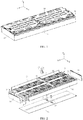
FIG. 1 is a three-dimensional diagram of a battery module in this application; -
FIG. 2 is an exploded view ofFIG. 1 , in which a top cover is omitted for clarity; -
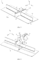
FIG. 3 is a three-dimensional diagram of a framework assembly of a battery module, in which a top cover, two side plates, and two end plates are omitted for clarity; -
FIG. 4 is an exploded view ofFIG. 3 ; -
FIG. 5 is an enlarged view of to a circled part inFIG. 4 ; -
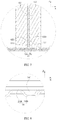
FIG. 6 is a cross-sectional view taken along a line A-A inFIG. 3 . -
FIG. 7 is an enlarged view of a large circled part inFIG. 6 ; -
FIG. 8 is an enlarged view of to a small circled part inFIG. 6 ; -
FIG. 9 is a three-dimensional diagram of a securing clip in a framework assembly; and -
FIG. 10 is a main view ofFIG. 9 . - To make the objectives, technical solutions, and advantages of this application clearer, this application is further described below in detail with reference to the accompanying drawings and embodiments. It should be understood that specific embodiments described herein are merely intended to explain this application, rather than limiting this application.
- In the descriptions of this application, unless otherwise specified and defined explicitly, the terms "first", "second", and "third" are merely intended for a purpose of description, and should not be understood as any indication or implication of relative importance, and the term "plurality of" means at least two (including two). Unless otherwise specified and defined explicitly, the term "connection" should be understood in its general sense. For example, the "connection" may be a fixed connection, a detachable connection, an integrated connection, an electrical connection, or a signal connection; and may be a direct connection, or an indirect connection through an intermediate medium. A person of ordinary skill in the art can understand specific meanings of these terms in this application based on specific situations.
- In the descriptions of the specification, it should be understood that the directional terms such as "above" and "below" described in the embodiments of this application are described as seen from the angles shown in the accompanying drawings, and should not be understood as a limitation to the embodiments of this application. The application is further described in detail below through the specific embodiments with reference to the accompanying drawings.
- Referring to
FIG. 1 and FIG. 2 , a battery module in this application includes aframework assembly 1 and a plurality of batteries 2, and theframework assembly 1 accommodates and firmly clamps the plurality of batteries 2. - Referring to
FIG. 1 to FIG. 10 , theframework assembly 1 may include afirst partition 11, twosecond partitions 12, a securingclip 13, twoside plates 15, twoend plates 16, and atop cover 18. Depending on an actual situation, theframework assembly 1 may further include aheat exchange plate 14 and aconnector 17. - The
first partition 11 extends in a second direction Y, eachsecond partition 12 extends in a first direction X, and the twosecond partitions 12 are located respectively on two sides of thefirst partition 11 in the first direction X and form a cross-shaped structure together with thefirst partition 11. The securingclip 13 fits with the twosecond partitions 12 and secures the twosecond partitions 12 to thefirst partition 11. - Each
side plate 15 extends in the second direction Y, and the twoside plates 15 are located respectively on two sides of the twosecond partitions 12 in the first direction X. Eachend plate 16 extends in the first direction X, and the twoend plates 16 are located respectively on two sides of thefirst partition 11 in the second direction Y and may be fixedly connected to the twoside plates 15 by welding. In this way, the twoside plates 15 and the twoend plates 16 together with thefirst partition 11 and the twosecond partitions 12 firmly clamp the plurality of batteries 2. It should be noted that, in this application, alternatively, a strap may be used to replace the twoside plates 15 and the twoend plates 16 to achieve the purpose of firmly clamping the plurality of batteries 2. - Referring to
FIG. 1 , thetop cover 18 is located above the plurality of batteries 2 and fitted to the twoside plates 15 and the twoend plates 16. - Referring to
FIG. 2 , the plurality of batteries 2 may be disposed into four battery units, and a plurality of batteries 2 in each battery unit are disposed side by side in the second direction Y between thesecond partition 12 and acorresponding end plate 16. - In the battery module of this application, the two
second partitions 12 of theframework assembly 1 are secured to thefirst partition 11 by using the securingclip 13, and this connection manner is simple and reliable, thereby facilitating assembly of theframework assembly 1 and improving the strength of connection between thesecond partitions 12 and thefirst partition 11. When the battery module is subjected to vibration and shock, thesecond partition 12 does not easily break away from thefirst partition 11 under the action of the securingclip 13, thereby improving the overall structural strength of the battery module. - Referring to
FIG. 4 , eachsecond partition 12 may have asecond body portion 121 and aconnection portion 122. Theconnection portion 122 is located between thefirst partition 11 and thesecond body portion 121 in the first direction X, and afirst cavity 1222 is provided in theconnection portion 122. Referring toFIG. 4 ,FIG. 9 , andFIG. 10 , the securingclip 13 may have athird body portion 131 and twoextension portions 132. Eachextension portion 132 is connected to thethird body portion 131 and extends in a third direction Z, and the twoextension portions 132 are spaced apart in the first direction X and form agroove 133 together with thethird body portion 131, that is, the securingclip 13 forms a U-shaped structure. - Referring to
FIG. 3, FIG. 4 ,FIG. 6 , andFIG. 7 , thethird body portion 131 of the securingclip 13 is located above theconnection portions 122 of the twosecond partitions 12, the twoextension portions 132 are accommodated in respectivefirst cavities 1222 formed by theconnection portions 122 of the twosecond partitions 12, and thefirst partition 11 passes through thegroove 133 in the second direction Y. In other words, the securingclip 13 fits with the twosecond partitions 12 through insertion. This fitting manner not only facilitates quick assembly, but also limits movement of the twosecond partitions 12 relative to thefirst partition 11 in the first direction X and the second direction Y under a clamping force applied to the twosecond partitions 12 by the twoextension portions 132 of the securingclip 13, thereby improving the strength of connection between thesecond partitions 12 and thefirst partition 11. - Referring to
FIG. 6 andFIG. 7 , a second steppedsurface 1221 is formed inside thefirst cavity 1222 of theconnection portion 122 of each second partition 12 (that is, the second steppedsurface 1221 is a part of the inner wall surface of theconnection portion 122, where the inner wall surface encircles to form the first cavity 1222). A first steppedsurface 1321 is formed inside eachextension portion 132 of the securingclip 13, and the first steppedsurface 1321 abuts against the second steppedsurface 1221 in the third direction Z. Herein, fitting between the first steppedsurface 1321 and the second steppedsurface 1221 limits movement of the twosecond partitions 12 relative to thefirst partition 11 in the third direction Z, thereby improving the strength of connection between thesecond partitions 12 and thefirst partition 11. - Referring to
FIG. 3 and FIG. 4 , a notch is provided in a part, corresponding to the securingclip 13, of thefirst partition 11, and thethird body portion 131 of the securingclip 13 is accommodated in the notch. In this case, a wall surface, forming the notch 113, of thefirst partition 11 clamps thethird body portion 131 of the securingclip 13, so as to limit movement of the securingclip 13 in the second direction Y, and further limit movement of the twosecond partitions 12 relative to thefirst partition 11 in the second direction Y. - In order not to increase the size of the battery module in the third direction Z, preferably, the securing
clip 13 does not protrude from the notch 113 of thefirst partition 11 in the third direction Z. - Referring to
FIG. 3 and FIG. 4 , theheat exchange plate 14 is located below thefirst partition 11 in the third direction Z and is formed with achannel 141, and theheat exchange plate 14 fits with the securingclip 13 to be mounted to the securingclip 13. A heat-conducting medium is disposed in thechannel 141, thereby implementing heat exchange between theheat exchange plate 14 and the plurality of batteries 2. - Referring to
FIG. 4 to FIG. 7 , a mountingslot 142 is provided in theheat exchange plate 14, and thefirst partition 11 may have afirst body portion 111 and a mountingportion 112. Thefirst body portion 111 of thefirst partition 11 extends in the third direction Z, and the mountingportion 112 is connected to thefirst body portion 111, extends in the first direction X, and is accommodated in the mountingslot 142. Herein, fitting between the mountingportion 112 of thefirst partition 11 and the mountingslot 142 of theheat exchange plate 14 facilitates quick mounting of theheat exchange plate 14 to the securingclip 13, thereby improving assembly efficiency of the battery module. - Referring to
FIG. 6 to FIG. 8 , theheat exchange plate 14 may include afirst plate 14A and asecond plate 14B. Thesecond plate 14B is located below thefirst plate 14A in the third direction Z and forms thechannel 141 together with thefirst plate 14A, and thesecond plate 14B is formed as a wave-like structure. - Referring to
FIG. 6 to FIG. 8 , theheat exchange plate 14 may have aposition locking hole 143. The securingclip 13 may further have aposition locking portion 134. Theposition locking portion 134 is disposed below theextension portion 132 in the third direction Z, and theposition locking portion 134 is accommodated in theposition locking hole 143 of theheat exchange plate 14. Herein, disposition of theposition locking hole 143 and theposition locking portion 134 provides a guide for the mounting of theheat exchange plate 14 and the securingclip 13, thereby not only improving assembly efficiency of the battery module, but also limiting movement of theheat exchange plate 14 relative to the securingclip 13 in the first direction X and the second direction Y. In this way, the overall structural strength of the battery module is improved. - In order to facilitate quick insertion of the
position locking portion 134 into theposition locking hole 143 to fit with theposition locking hole 143, theposition locking portion 134 may be formed as a tapered structure, and correspondingly theposition locking hole 143 is formed as a tapered hole. - Referring to
FIG. 9 andFIG. 10 , theposition locking portions 134 of the securingclip 13 may be disposed in pairs, and specifically one or more pairs of theposition locking portions 134 may be disposed. A pair ofposition locking portions 134 are respectively disposed below the twoextension portions 132, and the pair ofposition locking portions 134 are staggered in the first direction X. This staggered disposition of theposition locking portions 134 is conducive to limiting a mounting position of theheat exchange plate 14 relative to the securingclip 13 in the first direction X and the second direction Y, thereby facilitating quick mounting of theheat exchange plate 14 to the securingclip 13. In this way, assembly efficiency of the battery module is improved. Certainly, the pair ofposition locking portions 134 may alternatively be disposed in parallel in the first direction X. - Referring to
FIG. 3 and FIG. 4 , asecond cavity 1211 may be provided in thesecond body portion 121 of thesecond partition 12. Theconnector 17 is secured to theheat exchange plate 14 and communicates with thechannel 141 of theheat exchange plate 14, and theconnector 17 protrudes from thesecond cavity 1211 of thesecond body portion 121 of thesecond partition 12. Theconnector 17 is configured to communicate with an external heat-conducting medium storage apparatus, so that the heat-conducting medium circulates in thechannel 141 of theheat exchange plate 14 and the heat-conducting medium storage apparatus through theconnector 17 to exchange heat with the plurality of batteries 2. - Finally, a supplementary description of an assembly process of the
framework assembly 1 of the battery module is provided: (1) dispose the twosecond partitions 12 against each other in the middle; (2) insert the twoextension portions 132 of the securingclip 13 into thefirst cavities 1222 of theconnection portions 122 of the twosecond partitions 12; (3) move the twosecond partitions 12 to two sides respectively in the first direction X; (4) insert thefirst partition 11 into thegroove 133 of the securingclip 13 in the second direction Y, where in this case, the twoextension portions 132 of the securingclip 13 clamp the twosecond partitions 12 and thefirst partition 11 together, so as to firmly secure the twosecond partitions 12 to thefirst partition 11, completing assembly of the securingclip 13 with the twosecond partitions 12 and thefirst partition 11; (5) first connect theconnector 17 to theheat exchange plate 14, and then fit the two to the foregoing assembled structure as a whole from the lower part of thefirst partition 11; and (6) place the batteries 2, and mount the twoside plates 15 and the twoend plates 16. In this way, assembly of the battery module is completed. - Another embodiment of this application provides a battery pack including the foregoing battery module. The battery pack may include one or more battery modules, to provide a higher voltage and capacity.
- Another embodiment of this application further provides a powered device including the foregoing battery module. Batteries of the battery module may be used as a power supply of the powered device, or may be used as an energy storage unit of the powered device. Examples of the powered device may be a drone, an energy storage cabinet, a ship, a vehicle, and the like. The vehicle may be a new energy vehicle, including but not limited to a full electric vehicle, a hybrid electric vehicle, a plug-in hybrid electric vehicle, an electric bicycle, an electric scooter, an electric golf vehicle, an electric truck, an electric train, and the like. The vehicle is provided with a drive motor, and the drive motor is electrically connected to the battery module and fed with electric energy by the batteries of the battery module. The drive motor is connected to wheels of the vehicle through a transmission mechanism to drive the vehicle.
- Another embodiment of this application provides an assembly method for a battery module, where the assembly method is applied to the battery module provided in the foregoing embodiment. The method includes the following steps:
providing a plurality of batteries 2 and aframework assembly 1, where theframework assembly 1 includes afirst partition 11, twosecond partitions 12, and a securingclip 13; placing thefirst partition 11 in a second direction Y; mounting thesecond partitions 12 respectively on two sides of thefirst partition 11 in a first direction X, where thesecond partitions 12 form a cross-shaped structure together with thefirst partition 11; fitting the securingclip 13 to the twosecond partitions 12 and thefirst partition 11, so that the securingclip 13 secures the twosecond partitions 12 to thefirst partition 11; and disposing the plurality of batteries 2 on two sides of eachsecond partition 12 in the second direction Y. - In some embodiments, a
first cavity 1222 is provided in eachsecond partition 12, and the securingclip 13 has twoextension portions 132 and agroove 133 located between the twoextension portions 132. The twoextension portions 132 of the securingclip 13 are inserted intorespective cavities 1222 of the twosecond partitions 12. Thefirst partition 11 is inserted into thegroove 133. - In some embodiments, a
heat exchange plate 14 is provided, and theheat exchange plate 14 is connected below thefirst partition 11 in a third direction Z, where a channel is formed in theheat exchange plate 14. - In some embodiments, a
connector 17 is further provided, and theconnector 17 is connected to theheat exchange plate 14, where theconnector 17 communicates with the channel.
| 1. |
134. |
| 11. |
14. |
| 111. |
141. |
| 112. Mounting |
142. Mounting slot |
| 113. |
143. |
| 12. |
14A. |
| 121. |
14B. |
| 1211. |
15. |
| 122. |
16. |
| 1221. Second stepped |
17. |
| 1222. |
18. |
| 13. Securing clip | 2. |
| 131. Third body portion | X. |
| 132. Extension portion | |
| 1321. First stepped surface | Z. |
| 133. Groove |
Claims (17)
- A battery module, comprising a plurality of batteries (2) and a framework assembly (1), wherein the framework assembly (1) comprises a first partition (11), two second partitions (12), and a securing clip (13);
the first partition (11) extends in a second direction (Y);
each second partition (12) extends in a first direction (X), and the two second partitions (12) are located respectively on two sides of the first partition (11) in the first direction (X) and form a cross-shaped structure together with the first partition (11);
the securing clip (13) fits with the two second partitions (12) and secures the two second partitions (12) to the first partition (11); and
the plurality of batteries (2) are disposed on two sides of each second partition (12) of the framework assembly (1) in the second direction (Y). - The battery module according to claim 1, wherein
each second partition (12) has a second body portion (121) and a connection portion (122), the connection portion (122) is located between the first partition (11) and the second body portion (121) in the first direction (X), and a first cavity (1222) is formed in the connection portion (122);
the securing clip (13) has a third body portion (131) and two extension portions (132), each extension portion (132) is connected to the third body portion (131) and extends in a third direction (Z), and the two extension portions (132) are spaced apart in the first direction (X) and form a groove (133) together with the third body portion (131); and
the third body portion (131) is located above the connection portions (122) of the two second partitions (12), the two extension portions (132) are accommodated in respective first cavities (1222) of the connection portions (122) of the two second partitions (12), and the first partition (11) passes through the groove (133) in the second direction (Y). - The battery module according to claim 2, wherein
a second stepped surface (1221) is formed inside the first cavity (1222) of the connection portion (122); and
a first stepped surface (1321) is formed inside each extension portion (132), and the first stepped surface (1321) abuts against the second stepped surface (1221) in the third direction (Z). - The battery module according to claim 2 or 3, wherein a notch (113) is provided in a part, corresponding to the securing clip (13), of the first partition (11), and the third body portion (131) of the securing clip (13) is accommodated in the notch (113).
- The battery module according to any one of claims 2 to 4, wherein
the framework assembly (1) further comprises a heat exchange plate (14), the heat exchange plate (14) is located below the first partition (11) in the third direction (Z), and a channel (141) is formed in the heat exchange plate (14); and
the securing clip (13) fits with the heat exchange plate (14), so as to mount the heat exchange plate (14). - The battery module according to claim 5, wherein
the first partition (11) has a first body portion (111) and a mounting portion (112), the first body portion (111) extends in the third direction (Z), and the mounting portion (112) is connected to the first body portion (111) and extends in the first direction (X); and
a mounting slot (142) is provided in the heat exchange plate (14), and the mounting slot (142) accommodates the mounting portion (112) of the first partition (11). - The battery module according to claim 5 or 6, wherein the heat exchange plate (14) comprises a first plate (14A) and a second plate (14B), the second plate (14B) is located below the first plate (14A) in the third direction (Z) and forms the channel (141) together with the first plate (14A), and the second plate (14B) is formed as a wave-like structure.
- The battery module according to any one of claims 5 to 7, wherein
the heat exchange plate (14) has a position locking hole (143); and
the securing clip (13) further has a position locking portion (134), the position locking portion (134) disposed below the extension portion (132) in the third direction (Z), and the position locking portion (134) accommodated in the position locking hole (143) of the heat exchange plate 14. - The battery module according to claim 8, wherein the position locking portion (134) is formed as a tapered structure.
- The battery module according to claim 8 or 9, wherein the position locking portions (134) are disposed in pairs, a pair of position locking portions (134) are respectively disposed below the two extension portions (132), and the pair of position locking portions (134) are staggered in the first direction (X).
- The battery module according to any one of claims 5 to 10, wherein the framework assembly (1) further comprises a connector (17), the connector (17) is secured to the heat exchange plate (14), and the connector (17) is configured to connect the channel (141) to an external heat-conducting medium storage apparatus.
- A battery pack, comprising the battery module according to any one of claims 1 to 11.
- A powered device, comprising the battery module according to any one of claims 1 to 11.
- An assembly method for a battery module, comprising:providing a plurality of batteries (2) and a framework assembly (1), wherein the framework assembly (1) comprises a first partition (11), two second partitions (12), and a securing clip (13);placing the first partition (11) in a second direction (Y);mounting the second partitions (12) respectively on two sides of the first partition (11) in a first direction (X), wherein the second partitions (12) form a cross-shaped structure together with the first partition (11);fitting the securing clip (13) to the two second partitions (12) and the first partition (11), so that the securing clip (13) secures the two second partitions (12) to the first partition (11); anddisposing the plurality of batteries (2) on two sides of each second partition (12) in the second direction (Y).
- The assembly method for a battery module according to claim 14, wherein a first cavity (1222) is provided in each second partition (12), and the securing clip (13) has two extension portions (132) and a groove (133) located between the two extension portions (132);
the step of fitting the securing clip (13) to the two second partitions (12) and the first partition (11), so that the securing clip (13) secures the two second partitions (12) to the first partition (11), further comprises:inserting the two extension portions (132) of the securing clip (13) into respective cavities (1222) of the two second partitions (12); andinserting the first partition (11) into the groove (133). - The assembly method for a battery module according to claim 14 or 15, wherein the method further comprises:providing a heat exchange plate (14); andconnecting the heat exchange plate (14) below the first partition (11) in a third direction (Z), wherein a channel is formed in the heat exchange plate (14).
- The assembly method for a battery module according to claim 16, wherein the method further comprises:providing a connector (17); andconnecting the connector (17) to the heat exchange plate (14), wherein the connector (17) communicates with the channel.
Applications Claiming Priority (2)
| Application Number | Priority Date | Filing Date | Title |
|---|---|---|---|
| CN201921285749.XU CN210576067U (en) | 2019-08-09 | 2019-08-09 | Battery module |
| PCT/CN2020/104708 WO2021027536A1 (en) | 2019-08-09 | 2020-07-26 | Battery module, battery pack, electrical device and method for assembling battery module |
Publications (3)
| Publication Number | Publication Date |
|---|---|
| EP3806183A1 true EP3806183A1 (en) | 2021-04-14 |
| EP3806183A4 EP3806183A4 (en) | 2021-08-25 |
| EP3806183B1 EP3806183B1 (en) | 2022-06-08 |
Family
ID=70636238
Family Applications (1)
| Application Number | Title | Priority Date | Filing Date |
|---|---|---|---|
| EP20817182.7A Active EP3806183B1 (en) | 2019-08-09 | 2020-07-26 | Battery module, battery pack, electrical device and method for assembling battery module |
Country Status (4)
| Country | Link |
|---|---|
| US (1) | US12074335B2 (en) |
| EP (1) | EP3806183B1 (en) |
| CN (1) | CN210576067U (en) |
| WO (1) | WO2021027536A1 (en) |
Families Citing this family (3)
| Publication number | Priority date | Publication date | Assignee | Title |
|---|---|---|---|---|
| CN210576067U (en) | 2019-08-09 | 2020-05-19 | 宁德时代新能源科技股份有限公司 | Battery module |
| CN113422126A (en) * | 2021-06-23 | 2021-09-21 | 浙江银轮机械股份有限公司 | Cooling plate, flow channel plate and manufacturing method thereof |
| US12009540B2 (en) * | 2022-10-13 | 2024-06-11 | Sk On Co., Ltd. | Eco-friendly power source such as battery module for transportation vehicle |
Family Cites Families (16)
| Publication number | Priority date | Publication date | Assignee | Title |
|---|---|---|---|---|
| DE102011084660B4 (en) | 2011-10-18 | 2018-02-15 | Bayerische Motoren Werke Aktiengesellschaft | Device for power supply |
| JP6273824B2 (en) * | 2013-12-20 | 2018-02-07 | アイコム株式会社 | Storage box partition member and storage box having the same |
| KR102314041B1 (en) * | 2015-03-12 | 2021-10-18 | 삼성에스디아이 주식회사 | Battery pack |
| CN104859717B (en) * | 2015-04-13 | 2017-07-11 | 中航爱维客汽车有限公司 | Electric light bus body frame structure for automotive and electric light bus |
| CN106207029B (en) * | 2016-07-13 | 2019-01-15 | 精功(绍兴)复合材料有限公司 | A kind of batteries of electric automobile pallet and its manufacturing method |
| DE102016113481A1 (en) * | 2016-07-21 | 2018-01-25 | Erbslöh Aluminium Gmbh | Housing for battery cells or battery cell modules |
| CN106601958B (en) * | 2017-02-13 | 2023-07-18 | 保力新(无锡)动力系统有限公司 | A fixing structure for a battery module |
| DE102017104359B4 (en) | 2017-03-02 | 2024-09-26 | Kirchhoff Automotive Deutschland Gmbh | Battery housing for an electric motor-driven vehicle and use of a tolerance compensation element therefor |
| DE102017206988A1 (en) * | 2017-04-26 | 2018-10-31 | Mahle Lnternational Gmbh | accumulator |
| DE102017110978A1 (en) * | 2017-05-19 | 2018-11-22 | Dr. Ing. H.C. F. Porsche Aktiengesellschaft | Frame structure for receiving a battery device |
| DE102017005328B4 (en) * | 2017-06-02 | 2024-11-21 | Audi Ag | energy storage arrangement and motor vehicle |
| DE102017005329A1 (en) * | 2017-06-02 | 2018-12-06 | Audi Ag | Method of manufacturing a battery tray |
| CN207607543U (en) * | 2017-11-27 | 2018-07-13 | 深圳市大富科技股份有限公司 | A kind of chassis assembly of electric vehicle, chassis platform and electric vehicle |
| CN111052494B (en) | 2018-01-31 | 2024-05-07 | 松下知识产权经营株式会社 | Battery modules and battery packs |
| CN109921144A (en) * | 2019-03-29 | 2019-06-21 | 潍柴动力股份有限公司 | The coldplate and electric car of battery |
| CN210576067U (en) * | 2019-08-09 | 2020-05-19 | 宁德时代新能源科技股份有限公司 | Battery module |
-
2019
- 2019-08-09 CN CN201921285749.XU patent/CN210576067U/en active Active
-
2020
- 2020-07-26 EP EP20817182.7A patent/EP3806183B1/en active Active
- 2020-07-26 WO PCT/CN2020/104708 patent/WO2021027536A1/en not_active Ceased
- 2020-12-15 US US17/123,027 patent/US12074335B2/en active Active
Also Published As
| Publication number | Publication date |
|---|---|
| US12074335B2 (en) | 2024-08-27 |
| WO2021027536A1 (en) | 2021-02-18 |
| EP3806183B1 (en) | 2022-06-08 |
| EP3806183A4 (en) | 2021-08-25 |
| CN210576067U (en) | 2020-05-19 |
| US20210104800A1 (en) | 2021-04-08 |
Similar Documents
| Publication | Publication Date | Title |
|---|---|---|
| JP6073583B2 (en) | Power supply device, vehicle including this power supply device, and power storage device | |
| JP7179731B2 (en) | Battery module and vehicle equipped with it | |
| CN106997936B (en) | Battery array retention | |
| US12074335B2 (en) | Battery module, battery pack, powered device, and assembly method for battery module | |
| CN111527621B (en) | Power supply device, vehicle provided with power supply device, and power storage device | |
| JP5208951B2 (en) | Battery system and electric vehicle or hybrid electric vehicle including the same | |
| CN110832665A (en) | Power supply device, vehicle including same, and power storage device | |
| JP6184959B2 (en) | Battery system, vehicle including battery system, and power storage device | |
| JP2020524888A (en) | Battery module, battery pack including the same, and automobile including the battery pack | |
| KR102317506B1 (en) | Battery pack | |
| JP2015207341A (en) | Power unit, electric vehicle with power unit, and power storage device | |
| KR20140060633A (en) | Battery module having bus bar assembly and battery pack comprising the same | |
| CN214898729U (en) | Cell modules and battery packs | |
| CN114883737A (en) | Thermal epoxy and positioning of electrochemical cells | |
| KR101799565B1 (en) | Battery Pack of Improved Safety | |
| WO2014034057A1 (en) | Battery system, electric vehicle equipped with battery system and electricity storage device | |
| WO2014024432A1 (en) | Vehicle battery system and electric vehicle provided with battery system | |
| US20240243408A1 (en) | Battery compartment, chassis, and vehicle | |
| JP2021136101A (en) | Battery module | |
| WO2018235557A1 (en) | POWER SUPPLY DEVICE, VEHICLE HAVING THE SAME, AND STORAGE DEVICE | |
| US20230302887A1 (en) | Traction battery packs with cell-to-pack battery systems housed within irregularly shaped enclosures | |
| KR100669333B1 (en) | Secondary battery module | |
| JP2011023181A (en) | Battery module, and vehicle having the same | |
| US10720619B2 (en) | Array frame mounting inserts for securing battery assemblies | |
| KR20130110951A (en) | Battery pack of compact structure |
Legal Events
| Date | Code | Title | Description |
|---|---|---|---|
| STAA | Information on the status of an ep patent application or granted ep patent |
Free format text: STATUS: UNKNOWN |
|
| STAA | Information on the status of an ep patent application or granted ep patent |
Free format text: STATUS: THE INTERNATIONAL PUBLICATION HAS BEEN MADE |
|
| PUAI | Public reference made under article 153(3) epc to a published international application that has entered the european phase |
Free format text: ORIGINAL CODE: 0009012 |
|
| STAA | Information on the status of an ep patent application or granted ep patent |
Free format text: STATUS: REQUEST FOR EXAMINATION WAS MADE |
|
| 17P | Request for examination filed |
Effective date: 20201211 |
|
| AK | Designated contracting states |
Kind code of ref document: A1 Designated state(s): AL AT BE BG CH CY CZ DE DK EE ES FI FR GB GR HR HU IE IS IT LI LT LU LV MC MK MT NL NO PL PT RO RS SE SI SK SM TR |
|
| AX | Request for extension of the european patent |
Extension state: BA ME |
|
| REG | Reference to a national code |
Ref country code: DE Ref legal event code: R079 Ref document number: 602020003497 Country of ref document: DE Free format text: PREVIOUS MAIN CLASS: H01M0002100000 Ipc: H01M0050204000 |
|
| A4 | Supplementary search report drawn up and despatched |
Effective date: 20210726 |
|
| RIC1 | Information provided on ipc code assigned before grant |
Ipc: H01M 50/204 20210101AFI20210720BHEP Ipc: H01M 50/258 20210101ALI20210720BHEP |
|
| GRAP | Despatch of communication of intention to grant a patent |
Free format text: ORIGINAL CODE: EPIDOSNIGR1 |
|
| STAA | Information on the status of an ep patent application or granted ep patent |
Free format text: STATUS: GRANT OF PATENT IS INTENDED |
|
| DAV | Request for validation of the european patent (deleted) | ||
| DAX | Request for extension of the european patent (deleted) | ||
| INTG | Intention to grant announced |
Effective date: 20220201 |
|
| GRAS | Grant fee paid |
Free format text: ORIGINAL CODE: EPIDOSNIGR3 |
|
| GRAA | (expected) grant |
Free format text: ORIGINAL CODE: 0009210 |
|
| STAA | Information on the status of an ep patent application or granted ep patent |
Free format text: STATUS: THE PATENT HAS BEEN GRANTED |
|
| AK | Designated contracting states |
Kind code of ref document: B1 Designated state(s): AL AT BE BG CH CY CZ DE DK EE ES FI FR GB GR HR HU IE IS IT LI LT LU LV MC MK MT NL NO PL PT RO RS SE SI SK SM TR |
|
| REG | Reference to a national code |
Ref country code: AT Ref legal event code: REF Ref document number: 1497549 Country of ref document: AT Kind code of ref document: T Effective date: 20220615 Ref country code: CH Ref legal event code: EP |
|
| REG | Reference to a national code |
Ref country code: DE Ref legal event code: R096 Ref document number: 602020003497 Country of ref document: DE |
|
| REG | Reference to a national code |
Ref country code: IE Ref legal event code: FG4D |
|
| REG | Reference to a national code |
Ref country code: LT Ref legal event code: MG9D |
|
| REG | Reference to a national code |
Ref country code: NL Ref legal event code: MP Effective date: 20220608 |
|
| PG25 | Lapsed in a contracting state [announced via postgrant information from national office to epo] |
Ref country code: SE Free format text: LAPSE BECAUSE OF FAILURE TO SUBMIT A TRANSLATION OF THE DESCRIPTION OR TO PAY THE FEE WITHIN THE PRESCRIBED TIME-LIMIT Effective date: 20220608 Ref country code: NO Free format text: LAPSE BECAUSE OF FAILURE TO SUBMIT A TRANSLATION OF THE DESCRIPTION OR TO PAY THE FEE WITHIN THE PRESCRIBED TIME-LIMIT Effective date: 20220908 Ref country code: LT Free format text: LAPSE BECAUSE OF FAILURE TO SUBMIT A TRANSLATION OF THE DESCRIPTION OR TO PAY THE FEE WITHIN THE PRESCRIBED TIME-LIMIT Effective date: 20220608 Ref country code: HR Free format text: LAPSE BECAUSE OF FAILURE TO SUBMIT A TRANSLATION OF THE DESCRIPTION OR TO PAY THE FEE WITHIN THE PRESCRIBED TIME-LIMIT Effective date: 20220608 Ref country code: GR Free format text: LAPSE BECAUSE OF FAILURE TO SUBMIT A TRANSLATION OF THE DESCRIPTION OR TO PAY THE FEE WITHIN THE PRESCRIBED TIME-LIMIT Effective date: 20220909 Ref country code: FI Free format text: LAPSE BECAUSE OF FAILURE TO SUBMIT A TRANSLATION OF THE DESCRIPTION OR TO PAY THE FEE WITHIN THE PRESCRIBED TIME-LIMIT Effective date: 20220608 Ref country code: BG Free format text: LAPSE BECAUSE OF FAILURE TO SUBMIT A TRANSLATION OF THE DESCRIPTION OR TO PAY THE FEE WITHIN THE PRESCRIBED TIME-LIMIT Effective date: 20220908 |
|
| REG | Reference to a national code |
Ref country code: AT Ref legal event code: MK05 Ref document number: 1497549 Country of ref document: AT Kind code of ref document: T Effective date: 20220608 |
|
| PG25 | Lapsed in a contracting state [announced via postgrant information from national office to epo] |
Ref country code: RS Free format text: LAPSE BECAUSE OF FAILURE TO SUBMIT A TRANSLATION OF THE DESCRIPTION OR TO PAY THE FEE WITHIN THE PRESCRIBED TIME-LIMIT Effective date: 20220608 Ref country code: LV Free format text: LAPSE BECAUSE OF FAILURE TO SUBMIT A TRANSLATION OF THE DESCRIPTION OR TO PAY THE FEE WITHIN THE PRESCRIBED TIME-LIMIT Effective date: 20220608 |
|
| PG25 | Lapsed in a contracting state [announced via postgrant information from national office to epo] |
Ref country code: NL Free format text: LAPSE BECAUSE OF FAILURE TO SUBMIT A TRANSLATION OF THE DESCRIPTION OR TO PAY THE FEE WITHIN THE PRESCRIBED TIME-LIMIT Effective date: 20220608 |
|
| PG25 | Lapsed in a contracting state [announced via postgrant information from national office to epo] |
Ref country code: SM Free format text: LAPSE BECAUSE OF FAILURE TO SUBMIT A TRANSLATION OF THE DESCRIPTION OR TO PAY THE FEE WITHIN THE PRESCRIBED TIME-LIMIT Effective date: 20220608 Ref country code: SK Free format text: LAPSE BECAUSE OF FAILURE TO SUBMIT A TRANSLATION OF THE DESCRIPTION OR TO PAY THE FEE WITHIN THE PRESCRIBED TIME-LIMIT Effective date: 20220608 Ref country code: RO Free format text: LAPSE BECAUSE OF FAILURE TO SUBMIT A TRANSLATION OF THE DESCRIPTION OR TO PAY THE FEE WITHIN THE PRESCRIBED TIME-LIMIT Effective date: 20220608 Ref country code: PT Free format text: LAPSE BECAUSE OF FAILURE TO SUBMIT A TRANSLATION OF THE DESCRIPTION OR TO PAY THE FEE WITHIN THE PRESCRIBED TIME-LIMIT Effective date: 20221010 Ref country code: ES Free format text: LAPSE BECAUSE OF FAILURE TO SUBMIT A TRANSLATION OF THE DESCRIPTION OR TO PAY THE FEE WITHIN THE PRESCRIBED TIME-LIMIT Effective date: 20220608 Ref country code: EE Free format text: LAPSE BECAUSE OF FAILURE TO SUBMIT A TRANSLATION OF THE DESCRIPTION OR TO PAY THE FEE WITHIN THE PRESCRIBED TIME-LIMIT Effective date: 20220608 Ref country code: CZ Free format text: LAPSE BECAUSE OF FAILURE TO SUBMIT A TRANSLATION OF THE DESCRIPTION OR TO PAY THE FEE WITHIN THE PRESCRIBED TIME-LIMIT Effective date: 20220608 Ref country code: AT Free format text: LAPSE BECAUSE OF FAILURE TO SUBMIT A TRANSLATION OF THE DESCRIPTION OR TO PAY THE FEE WITHIN THE PRESCRIBED TIME-LIMIT Effective date: 20220608 |
|
| PG25 | Lapsed in a contracting state [announced via postgrant information from national office to epo] |
Ref country code: PL Free format text: LAPSE BECAUSE OF FAILURE TO SUBMIT A TRANSLATION OF THE DESCRIPTION OR TO PAY THE FEE WITHIN THE PRESCRIBED TIME-LIMIT Effective date: 20220608 Ref country code: IS Free format text: LAPSE BECAUSE OF FAILURE TO SUBMIT A TRANSLATION OF THE DESCRIPTION OR TO PAY THE FEE WITHIN THE PRESCRIBED TIME-LIMIT Effective date: 20221008 |
|
| REG | Reference to a national code |
Ref country code: DE Ref legal event code: R097 Ref document number: 602020003497 Country of ref document: DE |
|
| REG | Reference to a national code |
Ref country code: BE Ref legal event code: MM Effective date: 20220731 |
|
| PG25 | Lapsed in a contracting state [announced via postgrant information from national office to epo] |
Ref country code: MC Free format text: LAPSE BECAUSE OF FAILURE TO SUBMIT A TRANSLATION OF THE DESCRIPTION OR TO PAY THE FEE WITHIN THE PRESCRIBED TIME-LIMIT Effective date: 20220608 Ref country code: AL Free format text: LAPSE BECAUSE OF FAILURE TO SUBMIT A TRANSLATION OF THE DESCRIPTION OR TO PAY THE FEE WITHIN THE PRESCRIBED TIME-LIMIT Effective date: 20220608 |
|
| PLBE | No opposition filed within time limit |
Free format text: ORIGINAL CODE: 0009261 |
|
| STAA | Information on the status of an ep patent application or granted ep patent |
Free format text: STATUS: NO OPPOSITION FILED WITHIN TIME LIMIT |
|
| PG25 | Lapsed in a contracting state [announced via postgrant information from national office to epo] |
Ref country code: LU Free format text: LAPSE BECAUSE OF NON-PAYMENT OF DUE FEES Effective date: 20220726 Ref country code: DK Free format text: LAPSE BECAUSE OF FAILURE TO SUBMIT A TRANSLATION OF THE DESCRIPTION OR TO PAY THE FEE WITHIN THE PRESCRIBED TIME-LIMIT Effective date: 20220608 |
|
| 26N | No opposition filed |
Effective date: 20230310 |
|
| PG25 | Lapsed in a contracting state [announced via postgrant information from national office to epo] |
Ref country code: SI Free format text: LAPSE BECAUSE OF FAILURE TO SUBMIT A TRANSLATION OF THE DESCRIPTION OR TO PAY THE FEE WITHIN THE PRESCRIBED TIME-LIMIT Effective date: 20220608 Ref country code: BE Free format text: LAPSE BECAUSE OF NON-PAYMENT OF DUE FEES Effective date: 20220731 |
|
| P01 | Opt-out of the competence of the unified patent court (upc) registered |
Effective date: 20230516 |
|
| PG25 | Lapsed in a contracting state [announced via postgrant information from national office to epo] |
Ref country code: IE Free format text: LAPSE BECAUSE OF NON-PAYMENT OF DUE FEES Effective date: 20220726 |
|
| PG25 | Lapsed in a contracting state [announced via postgrant information from national office to epo] |
Ref country code: IT Free format text: LAPSE BECAUSE OF FAILURE TO SUBMIT A TRANSLATION OF THE DESCRIPTION OR TO PAY THE FEE WITHIN THE PRESCRIBED TIME-LIMIT Effective date: 20220608 |
|
| REG | Reference to a national code |
Ref country code: CH Ref legal event code: PL |
|
| PG25 | Lapsed in a contracting state [announced via postgrant information from national office to epo] |
Ref country code: MK Free format text: LAPSE BECAUSE OF FAILURE TO SUBMIT A TRANSLATION OF THE DESCRIPTION OR TO PAY THE FEE WITHIN THE PRESCRIBED TIME-LIMIT Effective date: 20220608 Ref country code: CY Free format text: LAPSE BECAUSE OF FAILURE TO SUBMIT A TRANSLATION OF THE DESCRIPTION OR TO PAY THE FEE WITHIN THE PRESCRIBED TIME-LIMIT Effective date: 20220608 Ref country code: CH Free format text: LAPSE BECAUSE OF NON-PAYMENT OF DUE FEES Effective date: 20230731 |
|
| PG25 | Lapsed in a contracting state [announced via postgrant information from national office to epo] |
Ref country code: HU Free format text: LAPSE BECAUSE OF FAILURE TO SUBMIT A TRANSLATION OF THE DESCRIPTION OR TO PAY THE FEE WITHIN THE PRESCRIBED TIME-LIMIT; INVALID AB INITIO Effective date: 20200726 |
|
| PG25 | Lapsed in a contracting state [announced via postgrant information from national office to epo] |
Ref country code: TR Free format text: LAPSE BECAUSE OF FAILURE TO SUBMIT A TRANSLATION OF THE DESCRIPTION OR TO PAY THE FEE WITHIN THE PRESCRIBED TIME-LIMIT Effective date: 20220608 |
|
| REG | Reference to a national code |
Ref country code: DE Ref legal event code: R081 Ref document number: 602020003497 Country of ref document: DE Owner name: CONTEMPORARY AMPEREX TECHNOLOGY (HONG KONG) LI, HK Free format text: FORMER OWNER: CONTEMPORARY AMPEREX TECHNOLOGY CO., LIMITED, CITY FUJIAN, JIAOCHENG DISTRICT NINGDE, CN |
|
| REG | Reference to a national code |
Ref country code: GB Ref legal event code: 732E Free format text: REGISTERED BETWEEN 20240822 AND 20240828 |
|
| PG25 | Lapsed in a contracting state [announced via postgrant information from national office to epo] |
Ref country code: MT Free format text: LAPSE BECAUSE OF FAILURE TO SUBMIT A TRANSLATION OF THE DESCRIPTION OR TO PAY THE FEE WITHIN THE PRESCRIBED TIME-LIMIT Effective date: 20220608 |
|
| PG25 | Lapsed in a contracting state [announced via postgrant information from national office to epo] |
Ref country code: BG Free format text: LAPSE BECAUSE OF FAILURE TO SUBMIT A TRANSLATION OF THE DESCRIPTION OR TO PAY THE FEE WITHIN THE PRESCRIBED TIME-LIMIT Effective date: 20220608 |
|
| PG25 | Lapsed in a contracting state [announced via postgrant information from national office to epo] |
Ref country code: BG Free format text: LAPSE BECAUSE OF FAILURE TO SUBMIT A TRANSLATION OF THE DESCRIPTION OR TO PAY THE FEE WITHIN THE PRESCRIBED TIME-LIMIT Effective date: 20220608 |
|
| PGFP | Annual fee paid to national office [announced via postgrant information from national office to epo] |
Ref country code: GB Payment date: 20250605 Year of fee payment: 6 |
|
| PGFP | Annual fee paid to national office [announced via postgrant information from national office to epo] |
Ref country code: FR Payment date: 20250610 Year of fee payment: 6 |
|
| PGFP | Annual fee paid to national office [announced via postgrant information from national office to epo] |
Ref country code: DE Payment date: 20250604 Year of fee payment: 6 |
|
| PG25 | Lapsed in a contracting state [announced via postgrant information from national office to epo] |
Ref country code: CH Free format text: THE PATENT HAS BEEN ANNULLED BY A DECISION OF A NATIONAL AUTHORITY Effective date: 20230731 |