EP3805535B1 - Exhaust heat recovery device - Google Patents
Exhaust heat recovery device Download PDFInfo
- Publication number
- EP3805535B1 EP3805535B1 EP19806896.7A EP19806896A EP3805535B1 EP 3805535 B1 EP3805535 B1 EP 3805535B1 EP 19806896 A EP19806896 A EP 19806896A EP 3805535 B1 EP3805535 B1 EP 3805535B1
- Authority
- EP
- European Patent Office
- Prior art keywords
- exhaust gas
- gas flow
- flow passage
- heat
- exhaust
- Prior art date
- Legal status (The legal status is an assumption and is not a legal conclusion. Google has not performed a legal analysis and makes no representation as to the accuracy of the status listed.)
- Active
Links
Images



Classifications
-
- F—MECHANICAL ENGINEERING; LIGHTING; HEATING; WEAPONS; BLASTING
- F01—MACHINES OR ENGINES IN GENERAL; ENGINE PLANTS IN GENERAL; STEAM ENGINES
- F01N—GAS-FLOW SILENCERS OR EXHAUST APPARATUS FOR MACHINES OR ENGINES IN GENERAL; GAS-FLOW SILENCERS OR EXHAUST APPARATUS FOR INTERNAL-COMBUSTION ENGINES
- F01N3/00—Exhaust or silencing apparatus having means for purifying, rendering innocuous, or otherwise treating exhaust
- F01N3/08—Exhaust or silencing apparatus having means for purifying, rendering innocuous, or otherwise treating exhaust for rendering innocuous
- F01N3/10—Exhaust or silencing apparatus having means for purifying, rendering innocuous, or otherwise treating exhaust for rendering innocuous by thermal or catalytic conversion of noxious components of exhaust
- F01N3/18—Exhaust or silencing apparatus having means for purifying, rendering innocuous, or otherwise treating exhaust for rendering innocuous by thermal or catalytic conversion of noxious components of exhaust characterised by methods of operation; Control
- F01N3/20—Exhaust or silencing apparatus having means for purifying, rendering innocuous, or otherwise treating exhaust for rendering innocuous by thermal or catalytic conversion of noxious components of exhaust characterised by methods of operation; Control specially adapted for catalytic conversion
- F01N3/2006—Periodically heating or cooling catalytic reactors, e.g. at cold starting or overheating
- F01N3/2013—Periodically heating or cooling catalytic reactors, e.g. at cold starting or overheating using electric or magnetic heating means
-
- F—MECHANICAL ENGINEERING; LIGHTING; HEATING; WEAPONS; BLASTING
- F01—MACHINES OR ENGINES IN GENERAL; ENGINE PLANTS IN GENERAL; STEAM ENGINES
- F01N—GAS-FLOW SILENCERS OR EXHAUST APPARATUS FOR MACHINES OR ENGINES IN GENERAL; GAS-FLOW SILENCERS OR EXHAUST APPARATUS FOR INTERNAL-COMBUSTION ENGINES
- F01N5/00—Exhaust or silencing apparatus combined or associated with devices profiting by exhaust energy
- F01N5/02—Exhaust or silencing apparatus combined or associated with devices profiting by exhaust energy the devices using heat
-
- F—MECHANICAL ENGINEERING; LIGHTING; HEATING; WEAPONS; BLASTING
- F01—MACHINES OR ENGINES IN GENERAL; ENGINE PLANTS IN GENERAL; STEAM ENGINES
- F01N—GAS-FLOW SILENCERS OR EXHAUST APPARATUS FOR MACHINES OR ENGINES IN GENERAL; GAS-FLOW SILENCERS OR EXHAUST APPARATUS FOR INTERNAL-COMBUSTION ENGINES
- F01N13/00—Exhaust or silencing apparatus characterised by constructional features
- F01N13/08—Other arrangements or adaptations of exhaust conduits
-
- F—MECHANICAL ENGINEERING; LIGHTING; HEATING; WEAPONS; BLASTING
- F01—MACHINES OR ENGINES IN GENERAL; ENGINE PLANTS IN GENERAL; STEAM ENGINES
- F01N—GAS-FLOW SILENCERS OR EXHAUST APPARATUS FOR MACHINES OR ENGINES IN GENERAL; GAS-FLOW SILENCERS OR EXHAUST APPARATUS FOR INTERNAL-COMBUSTION ENGINES
- F01N3/00—Exhaust or silencing apparatus having means for purifying, rendering innocuous, or otherwise treating exhaust
- F01N3/02—Exhaust or silencing apparatus having means for purifying, rendering innocuous, or otherwise treating exhaust for cooling, or for removing solid constituents of, exhaust
- F01N3/0205—Exhaust or silencing apparatus having means for purifying, rendering innocuous, or otherwise treating exhaust for cooling, or for removing solid constituents of, exhaust using heat exchangers
-
- F—MECHANICAL ENGINEERING; LIGHTING; HEATING; WEAPONS; BLASTING
- F01—MACHINES OR ENGINES IN GENERAL; ENGINE PLANTS IN GENERAL; STEAM ENGINES
- F01N—GAS-FLOW SILENCERS OR EXHAUST APPARATUS FOR MACHINES OR ENGINES IN GENERAL; GAS-FLOW SILENCERS OR EXHAUST APPARATUS FOR INTERNAL-COMBUSTION ENGINES
- F01N2240/00—Combination or association of two or more different exhaust treating devices, or of at least one such device with an auxiliary device, not covered by indexing codes F01N2230/00 or F01N2250/00, one of the devices being
- F01N2240/02—Combination or association of two or more different exhaust treating devices, or of at least one such device with an auxiliary device, not covered by indexing codes F01N2230/00 or F01N2250/00, one of the devices being a heat exchanger
-
- F—MECHANICAL ENGINEERING; LIGHTING; HEATING; WEAPONS; BLASTING
- F01—MACHINES OR ENGINES IN GENERAL; ENGINE PLANTS IN GENERAL; STEAM ENGINES
- F01N—GAS-FLOW SILENCERS OR EXHAUST APPARATUS FOR MACHINES OR ENGINES IN GENERAL; GAS-FLOW SILENCERS OR EXHAUST APPARATUS FOR INTERNAL-COMBUSTION ENGINES
- F01N2240/00—Combination or association of two or more different exhaust treating devices, or of at least one such device with an auxiliary device, not covered by indexing codes F01N2230/00 or F01N2250/00, one of the devices being
- F01N2240/36—Combination or association of two or more different exhaust treating devices, or of at least one such device with an auxiliary device, not covered by indexing codes F01N2230/00 or F01N2250/00, one of the devices being an exhaust flap
-
- F—MECHANICAL ENGINEERING; LIGHTING; HEATING; WEAPONS; BLASTING
- F01—MACHINES OR ENGINES IN GENERAL; ENGINE PLANTS IN GENERAL; STEAM ENGINES
- F01N—GAS-FLOW SILENCERS OR EXHAUST APPARATUS FOR MACHINES OR ENGINES IN GENERAL; GAS-FLOW SILENCERS OR EXHAUST APPARATUS FOR INTERNAL-COMBUSTION ENGINES
- F01N2410/00—By-passing, at least partially, exhaust from inlet to outlet of apparatus, to atmosphere or to other device
-
- Y—GENERAL TAGGING OF NEW TECHNOLOGICAL DEVELOPMENTS; GENERAL TAGGING OF CROSS-SECTIONAL TECHNOLOGIES SPANNING OVER SEVERAL SECTIONS OF THE IPC; TECHNICAL SUBJECTS COVERED BY FORMER USPC CROSS-REFERENCE ART COLLECTIONS [XRACs] AND DIGESTS
- Y02—TECHNOLOGIES OR APPLICATIONS FOR MITIGATION OR ADAPTATION AGAINST CLIMATE CHANGE
- Y02T—CLIMATE CHANGE MITIGATION TECHNOLOGIES RELATED TO TRANSPORTATION
- Y02T10/00—Road transport of goods or passengers
- Y02T10/10—Internal combustion engine [ICE] based vehicles
- Y02T10/12—Improving ICE efficiencies
Definitions
- the present invention relates to an exhaust heat recovery apparatus.
- the exhaust heat recovery apparatus disclosed in the patent document 1 includes a main exhaust gas flow passage, a bypass flow passage, a heat exchanger and a valve device.
- the main exhaust gas flow passage introduces an exhaust gas of an internal combustion engine.
- the bypass flow passage is a flow passage that bypasses the main exhaust gas flow passage.
- the heat exchanger is provided in the bypass flow passage for exchanging heat between the exhaust gas in the bypass flow passage and a coolant of the internal combustion engine.
- the valve device opens and closes the main exhaust gas flow passage and the bypass flow passage downstream of the heat exchanger. Between the valve device and the heat exchanger, the bypass flow passage is connected to an EGR via a recirculation passage.
- the present invention is characterized by an exhaust heat recovery apparatus including a bypass part having a main exhaust gas flow passage into which an exhaust gas of an internal combustion engine is introduced, a heat exchange part disposed adjacent to the bypass part and having a heat exchanger for exchanging heat between the exhaust gas and a heat carrier, a gas flow-in port disposed upstream of the heat exchange part in an exhaust gas flow, the gas flow-in port causing the exhaust gas to flow in the heat exchange part from the bypass part, a gas flow-out port disposed downstream of the gas flow-in port in the exhaust gas flow, the gas flow-out port causing the exhaust gas to flow out to the bypass part from the heat exchange part, and a valve including a rotatable rotation shaft, a valve body having one end fixed to the rotation shaft, and an actuator for rotating the rotation shaft, wherein a rotating end of the valve body is disposed downstream of the gas flow-out port in the exhaust gas flow, and the valve is provided in the main exhaust gas flow passage of the bypass part, wherein a heat exchange flow passage, through which
- An exhaust heat recovery apparatus 1 is disposed in the middle of an exhaust pipe of an internal combustion engine of a vehicle, and recovers heat of an exhaust gas of the internal combustion engine.
- the exhaust heat recovery apparatus 1 operates in a heat recovery mode that recovers the heat of the exhaust gas or in a non-recovery mode that does not recover the heat.
- an upper side and a lower side of the exhaust heat recovery apparatus 1 in FIG. 1 are defined as an upper part and a lower part, respectively.
- an orientation of the exhaust heat recovery apparatus 1 when mounted on the vehicle is not limited to that shown in FIG. 1 .
- the exhaust heat recovery apparatus 1 includes a main exhaust gas flow passage 20A, a heat exchange flow passage 10A, a heat exchanger 111, and a valve 30.
- the main exhaust gas flow passage 20A has a bypass part (bypass pipe) 20 into which an exhaust gas G1 of the internal combustion engine is introduced.
- the exhaust gas G1 passing through the bypass part 20 bypasses the heat exchanger 111.
- the heat exchange flow passage 10A has a heat exchange part (heat exchange pipe) 10 which branches from the main exhaust gas flow passage 20A at a gas flow-in port 11 and returns to the main exhaust gas flow passage 20A at a gas flow-out port 12.
- the heat exchange part 10 is positioned adjacent to the bypass part 20.
- the heat exchanger 111 is disposed in the heat exchange flow passage 10A, and exchanges heat between the exhaust gas G1 and a heat carrier W such as a coolant.
- the valve 30 is a so-called flap valve, which is disposed downstream of the gas flow-in port 11 of the main exhaust gas flow passage 20A and has a valve body 135 which opens and closes the main exhaust gas flow passage 20A.
- An exhaust gas G1e which has returned to the main exhaust gas flow passage 20A through the gas flow-out port 12, flows around the valve 30 through a subsidiary flow passage 155 that is not closed by the valve body 135 in a closed position P1, and returns to the main exhaust gas flow passage 20A.
- exhaust gases G1a and G1b exchange heat with the heat carrier W by the heat exchanger 111 while passing through the heat exchange flow passage 10A, and an exhaust heat is recovered.
- an exhaust gas G1f is discharged as exhaust gases G1g and G2 through the main exhaust gas flow passage 20A (bypass passage of the heat exchanger 111).
- a pressure in the main exhaust gas flow passage 20A is high on an upstream side of the valve 30, and the pressure is low on a downstream side of the valve 30.
- a pressure in the subsidiary flow passage 155 disposed upstream of the valve 30 is also high because the pressure is not affected by an exhaust gas G1g discharged from the valve 30.
- the valve opening When the valve body 135 is operated between the open state and the closed state by a thermoactuator 200 or the like described later, the valve opening may become unstable due to aging deterioration of the actuator 200 or the like.
- exhaust heat recovery apparatus 1 of the present embodiment even if the valve opening is unstable, the differential pressure of the heat exchange flow passage 10A (differential pressure between the upstream side and the downstream side of the heat exchanger 111) does not fluctuate due to a valve opening difference. Therefore, the heat recovery by the heat exchanger 111 in the non-recovery mode can be surely prevented.
- the exhaust gas G1a flows into the heat exchange flow passage 10A only slightly.
- a slight amount of the exhaust gas G1b entering the heat exchange flow passage 10A is returned to the subsidiary flow passage 155 upstream of the valve 30, and is affected by the degraded opening of the valve 30 for the first time when it flows downstream of the valve 30. Therefore, the differential pressure of the heat exchange flow passage 10A (differential pressure between the upstream side and the downstream side of the heat exchanger 111) is hard to fluctuate as mentioned above, and the heat recovery by the heat exchanger 111 in the non-recovery mode can be surely prevented.
- the subsidiary flow passage 155 functions as an insulating air layer, heat transfer from the bypass part 20 to the heat exchange part 10 can be suppressed. As a result, the heat recovery by the heat exchanger 111 in the non-recovery mode can be suppressed more reliably.
- a return flow passage 17 is provided on the main exhaust gas flow passage 20A side of the heat exchange flow passage 10A, that is, on the side of the heat exchanger 111 (upper side in FIG. 1 ), to turn around an exhaust gas G1d that has passed through the heat exchanger 111 toward the gas flow-out port 12. That is, the return flow passage 17 is disposed between the heat exchanger 111 and the bypass part 20 side inner wall of the heat exchange part 10. In the non-recovery mode in which the valve body 135 is in the open state, since the exhaust gas G1d does not flow through the return flow passage 17, the return flow passage 17 functions as the insulating air layer between the heat exchanger 111 and the main exhaust gas flow passage 20A.
- heat of the high-temperature exhaust gases G1f and G1g flowing through the main exhaust gas flow passage 20A can be avoided as much as possible from being transferred to the heat exchanger 111. That is, the heat recovery by the heat exchanger 111 in the non-recovery mode can be suppressed more reliably.
- the exhaust gas G1e flowing through the return flow passage 17 exchanges heat with the heat exchanger 111 again to recover the residual heat. Therefore, the heat exchange efficiency is improved.
- An insulating air layer 125 is formed downstream of the gas flow-in port 11 between the main exhaust gas flow passage 20A and the heat exchange flow passage 10A.
- the bypass part 20 constituting the main exhaust gas flow passage 20A includes a bypass part main body 120.
- the bypass part main body 120 is formed into a hollow-cylindrical shape (e.g., a rectangular cylindrical shape, a cylindrical shape, or the like) by a metal, for example, and extends in the front and rear directions of the vehicle.
- the bypass part main body 120 includes a cylindrical gas inlet port 121 provided on an intake side of the exhaust gas G1 and a cylindrical gas outlet port 122 provided on an exhaust side of the exhaust gas G2.
- the valve pipe 35 forming a part of the valve 30 is disposed substantially in the center of the bypass part main body 120.
- the valve pipe 35 of the valve 30 constitutes a double pipe structure with the bypass part main body 120 of the bypass part 20.
- the valve pipe 35 let the main exhaust gas flow passage 20A communicate only within the valve pipe 35.
- An upstream end of the valve pipe 35 is fixed to an inner surface of the bypass part main body 120 and closes a space between the valve pipe 35 and the bypass part main body 120.
- the gas flow-out port 12 described above is arranged beside the valve pipe 35 along the axis line of the valve pipe 35, and the subsidiary flow passage 155 is formed around a circumference of the valve pipe 35.
- the downstream end of the valve pipe 35 is formed as an inclined portion which projects downwardly toward the downstream.
- the inclined portion constitutes a valve seat 31 against which the valve body 135 of the valve 30 abuts.
- the inclination of the valve seat 31 (inclined portion) is about 10 to 60 degrees with respect to the exhaust gas flow direction, although it is not limited to this range.
- the valve 30 includes a rotatable rotation shaft 140, the valve body 135 having one end fixed to the rotation shaft 140, and an actuator 200 for rotating the rotation shaft 140 (see FIG. 2 ).
- the rotating end 135a of the valve body 135 is disposed downstream of the gas flow-out port 12.
- a base end 135b of the valve body 135 may be disposed upstream of the rotation shaft 140.
- the valve body 135 is configured to swing in a direction D10 between the closed position P1 in contact with the valve seat 31 and the open position P2 away from the valve seat 31 in accordance with the rotation of the rotation shaft 140 by the actuator 200.
- the valve seat 31 has the inclined portion. Compared to the case where the valve seat 31 is perpendicular to the straight-flowing component G1f of the exhaust gas G1, the pressure receiving area of the valve body 135 receiving the straight-flowing component G1f can be increased when the valve seat 31 is inclined. Therefore, the load of the actuator 200 when rotating the valve body 135 from the closed position P1 to the open position P2 can be reduced, thereby improving the valve opening performance of the valve 30. Consequently, it is possible to switch from the heat recovery mode to the non-recovery mode quickly.
- the valve body 135 is biased toward the valve seat 31 by an elastic member (not shown) such as a spring. Therefore, the valve body 135 can be more reliably held in the closed position P1 in the heat recovery mode. Further, on a surface of an exhaust gas downstream side of the valve body 135, a weight (mass damper) 136 is attached. Therefore, resonance of the valve body 135 caused by pulsation of the exhaust gas can be suppressed by the mass of the weight 136.
- the heat exchange part 10 which constitutes the heat exchange flow passage 10A including the heat exchanger 111, includes a metal housing 10a.
- the heat exchanger 111 including a plurality of layers of exhaust passages 100 and a heat carrier flow passage unit 110 with a plurality of layers is provided in the housing 10a.
- An exhaust gas G1c flows through each of the exhaust passages 100.
- the heat carrier flow passage unit 110 has a plurality of layers of heat carrier flow passages 101 in which a heat carrier (e.g., a coolant) W circulates.
- the exhaust passages 100 and the heat carrier flow passages 101 are alternately laminated.
- the gas flow-in port 11 which communicates with the bypass part main body 120 and introduces the exhaust gas G1 (G1a) into the housing 10a, is formed at an upper portion of an upstream side of the housing 10a.
- the gas flow-in port 11 and the gas flow-out port 12 are disposed upstream of the valve 30.
- a gas distribution chamber 15 for distributing the exhaust gas G1a flowing into the heat exchange part 10 to the plurality of exhaust passages 100 (exhaust gas G1c) is formed.
- a gas convergence chamber 16 for converging the exhaust gas G1c flowing through the exhaust passages 100 (exhaust gas G1d) is formed.
- the exhaust gas G1d does not flow through the return flow passage 17, and the return flow passage 17 functions as the insulating air layer between the heat exchanger 111 and the main exhaust gas flow passage 20A. Therefore, the heat insulation between the bypass part 20 and the heat exchange part 10 can be improved, and the heat recovery by the heat exchanger 111 in the non-recovery mode can be suppressed.
- the exhaust gas G1d converged by the gas convergence chamber 16 is guided by the return flow passage 17 in a direction B1 opposite to the flow direction of the exhaust gas G1c in the exhaust passages 100 (i.e., heat exchange flow passage 10A), and flows into the bypass part main body 120 through the gas flow-out port 12.
- the B1 direction is also opposite to the flow direction of the exhaust gases G1f and G1g in the main exhaust gas flow passage 20A.
- the exhaust gas G1e flowing into the bypass part main body 120 flows in a B2 direction by the subsidiary flow passage 155 and is discharged as the exhaust gas G2.
- the exhaust gas G1c flowing through the exhaust passages 100 (becomes the exhaust gas G1d converged by the gas convergence chamber 16, and thereafter,) turns around in the B1 direction in the return flow passage 17.
- the residual heat of the exhaust gas G1d flowing through the return flow passage 17 can be recovered through the end surface 100A of the exhaust passages 100, thereby improving the heat recovery efficiency.
- the length of exhaust heat recovery apparatus 1 in the longitudinal direction (flow direction of the exhaust gas) can be reduced, and the exhaust heat recovery apparatus 1 can be reduced in size.
- an introducing pipe 220 for introducing the heat carrier (coolant) W into the heat carrier flow passages 101 is provided outside the housing 10a.
- the introducing pipe 220 is fixed by welding or the like to a heat carrier inlet 221 which is opened in the housing 10a.
- the actuator (e.g., a thermoactuator) 200 is attached to the outer wall of the housing 10a.
- the thermoactuator 200 includes a rod housing 203, a coupling element 204, and a cylinder housing 200a.
- the rod housing 203 contains a thermal expansion medium (wax in this embodiment), a piston rod or the like which moves axially in response to thermal expansion and thermal shrinkage of the wax.
- the coupling element 204 is attached to the distal end of the rod and engages with a protruded operator 145 of the above-described rotation shaft 140 and rotates the rotation shaft 140.
- the lower end of the cylinder housing 200a is fixed by welding or the like to a heat carrier outlet 222 which is opened in the housing 10a.
- a discharge pipe 202 for discharging the heat carrier W supplied from the heat carrier outlet 222 and flowing through the cylinder housing 200a is integrally provided in the center of the cylinder housing 200a.
- the cylinder housing 200a is fixed to the housing 10a by a metal bracket 201.
- the cylinder housing 200a and the rod housing 203 are joined by bolts 206 and nuts 207 via their flanges 205a and 205b.
- the exhaust gas G1 (G1f) is prevented from flowing into the bypass part main body 120 (main exhaust gas flow passage 20A) through the valve pipe 35 by the valve body 135.
- the exhaust gas G1 (G1a) flows into the heat exchange part 10 from the gas flow-in port 11 of the heat exchange part 10 and flows through the exhaust passages 100 as the exhaust gas G1c. Therefore, heat is exchanged between the heat carrier W flowing through the heat carrier flow passages 101 and the exhaust gas G1c flowing through the exhaust passages 100, and the heat of the exhaust gas G1 is recovered.
- the exhaust gas G1 flows through the bypass part main body 120 (main exhaust gas flow passage 20A) and is discharged from gas outlet port 122 as the exhaust gas G2.
- both the gas flow-in port 11 and the gas flow-out port 12 are disposed upstream of the valve 30, even if the valve opening of the valve 30 is unstable, the differential pressure between the gas flow-in port 11 and the gas flow-out port 12 is the same. That is, since the gas flow-out port 12 is disposed upstream of the valve 30, the internal pressure in the vicinity of the gas flow-out port 12 is not affected by the exhaust gas G1g flowing out from the valve 30. Therefore, since the differential pressure of the heat exchange flow passage 10A (differential pressure between the upstream side and the downstream side of the heat exchanger 111) does not change depending on the valve opening difference, it is possible to reliably prevent the heat recovery by the heat exchanger 111 in the non-recovery mode.
- valve seat 31 is formed as an inclined portion, it is possible to relatively reduce the displacement angle when rotating the valve body 135 from the closed position P1 to the open position P2 (rotation angle). Therefore, the valve opening performance of the valve 30 is improved, and the heat recovery by the heat exchanger in the non-recovery mode can be suppressed.
- the valve seat 31 is formed as an inclined portion, it is possible to increase the pressure receiving area that receives the straight-flowing component G1f of the exhaust gas G1. Therefore, it is possible to reduce the load of the actuator 200 when rotating the valve body 135 from the closed position P1 to the open position P2. As a result, the actuator 200 can be reduced in size, it is possible to improve the valve opening performance of the valve 30. Furthermore, the (downstream side) opening area of the valve 30 can be increased by the inclined portion, it is possible to reduce the flow resistance.
- an exhaust heat recovery apparatus 1A according to the second embodiment will be described. Note that the same reference numerals are assigned to the same or equivalent components as those of the exhaust heat recovery apparatus 1 of the first embodiment, and duplicate descriptions are omitted.
- the exhaust heat recovery apparatus 1A in this embodiment differs from the exhaust heat recovery apparatus 1 of the first embodiment in that a return flow passage 517 is disposed on an inner wall 520 on the heat exchange part 10 side of the bypass part 20.
- an exhaust gas plate member 300 (see Fig. 4 ) having an opening 300b formed on only one end is fixed by brazing on the inner wall 520 on the heat exchange part 10 side of the bypass part 20.
- the exhaust gas plate member 300 is manufactured by bending a metal plate or the like.
- the exhaust gas plate member 300 is joined to the inner wall 520 of the bypass part 20 by a flange 300a formed on the periphery avoiding the opening 300b.
- a gas flow-out port 512 is formed above the gas convergence chamber 16.
- the exhaust gas G1d passing through the exhaust passages 100 flows into a space 300c in the exhaust gas plate member 300 through the gas flow-out port 512.
- An exhaust gas G1h flowing into the space 300c flows in a B11 direction in the return flow passage 517 formed between the exhaust gas plate member 300 and the inner wall 520, and flows from the opening 300b to the bypass part 20 (subsidiary flow passage 155 of the bypass part 20).
- An exhaust gas G1i flowing into the bypass part 20 flows in a B12 direction through a gap (subsidiary flow passage 155) between the upper surface of the exhaust gas plate member 300 and the valve pipe 35, and is discharged as the exhaust gas G2.
- the bypass part 20 and the heat exchange part 10 are slightly separated from each other.
- This gap functions as an insulating air layer 125A between the main exhaust gas flow passage 20A (bypass part 20) and the heat exchange flow passage 10A (heat exchange part 10).
- the insulating air layer 125A achieves the same effects as the insulating air layer 125 of the first embodiment.
- the return flow passage 517 also functions as an insulating air layer between the heat exchanger 111 and the main exhaust gas flow passage 20A.
- heat of the high-temperature exhaust gases G1f and G1g flowing through the main exhaust gas flow passage 20A can be further avoided from being transferred to the heat exchanger 111. That is, the heat recovery by the heat exchanger 111 in the non-recovery mode can be suppressed more reliably.
- the heat recovery by the heat exchanger in the non-recovery mode can be suppressed by improving the valve opening performance and the heat insulation of the valve 30.
Landscapes
- Engineering & Computer Science (AREA)
- Chemical & Material Sciences (AREA)
- Combustion & Propulsion (AREA)
- Mechanical Engineering (AREA)
- General Engineering & Computer Science (AREA)
- Chemical Kinetics & Catalysis (AREA)
- Health & Medical Sciences (AREA)
- Toxicology (AREA)
- Exhaust Silencers (AREA)
Description
- The present invention relates to an exhaust heat recovery apparatus.
- Each of the
patent documents 1 and 2 below discloses an exhaust heat recovery apparatus. The exhaust heat recovery apparatus disclosed in thepatent document 1 includes a main exhaust gas flow passage, a bypass flow passage, a heat exchanger and a valve device. The main exhaust gas flow passage introduces an exhaust gas of an internal combustion engine. The bypass flow passage is a flow passage that bypasses the main exhaust gas flow passage. The heat exchanger is provided in the bypass flow passage for exchanging heat between the exhaust gas in the bypass flow passage and a coolant of the internal combustion engine. The valve device opens and closes the main exhaust gas flow passage and the bypass flow passage downstream of the heat exchanger. Between the valve device and the heat exchanger, the bypass flow passage is connected to an EGR via a recirculation passage. -
- PATENT DOCUMENT 1 :
JP2016-44666A - PATENT DOCUMENT 2 :
JP2012-184678A - According to the exhaust heat recovery apparatus disclosed in the
patent document 1, there is a concern that the valve opening becomes unstable due to aging deterioration of the valve device or the like. Unstable valve opening affects the exhaust flow and increases heat recovery by the heat exchanger in a non-recovery mode. - It is an object of the present disclosure to provide an exhaust heat recovery apparatus capable of suppressing the heat recovery by the heat exchanger in the non-recovery mode.
- The present invention is characterized by an exhaust heat recovery apparatus including a bypass part having a main exhaust gas flow passage into which an exhaust gas of an internal combustion engine is introduced, a heat exchange part disposed adjacent to the bypass part and having a heat exchanger for exchanging heat between the exhaust gas and a heat carrier, a gas flow-in port disposed upstream of the heat exchange part in an exhaust gas flow, the gas flow-in port causing the exhaust gas to flow in the heat exchange part from the bypass part, a gas flow-out port disposed downstream of the gas flow-in port in the exhaust gas flow, the gas flow-out port causing the exhaust gas to flow out to the bypass part from the heat exchange part, and a valve including a rotatable rotation shaft, a valve body having one end fixed to the rotation shaft, and an actuator for rotating the rotation shaft, wherein a rotating end of the valve body is disposed downstream of the gas flow-out port in the exhaust gas flow, and the valve is provided in the main exhaust gas flow passage of the bypass part, wherein a heat exchange flow passage, through which the exhaust gas flows into the heat exchange part from the main exhaust gas flow passage through the gas flow-in port and returns to the main exhaust gas flow passage from the heat exchange part through the gas flow-out port, is formed, and on a most downstream side of the heat exchange flow passage, a return flow passage, in which the exhaust gas flows in a direction opposite to a direction of the
-
- [
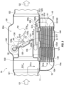
FIG. 1] FIG. 1 is a cross-sectional view of an exhaust heat recovery apparatus according to the first embodiment. - [
FIG. 2] FIG. 2 is a perspective view of the exhaust heat recovery apparatus. - [
FIG. 3] FIG. 3 is a cross-sectional view of an exhaust heat recovery apparatus according to the second embodiment. - [
FIG. 4] FIG. 4 is a perspective view of exhaust gas plate member of the exhaust heat recovery apparatus. - Embodiments of the present invention will be described below with reference to the drawings.
- An exhaust
heat recovery apparatus 1 according to the first embodiment is disposed in the middle of an exhaust pipe of an internal combustion engine of a vehicle, and recovers heat of an exhaust gas of the internal combustion engine. The exhaustheat recovery apparatus 1 operates in a heat recovery mode that recovers the heat of the exhaust gas or in a non-recovery mode that does not recover the heat. For convenience of explanation, an upper side and a lower side of the exhaustheat recovery apparatus 1 inFIG. 1 are defined as an upper part and a lower part, respectively. However, an orientation of the exhaustheat recovery apparatus 1 when mounted on the vehicle is not limited to that shown inFIG. 1 . - As shown in
FIG. 1 , the exhaustheat recovery apparatus 1 includes a main exhaustgas flow passage 20A, a heatexchange flow passage 10A, aheat exchanger 111, and avalve 30. The main exhaustgas flow passage 20A has a bypass part (bypass pipe) 20 into which an exhaust gas G1 of the internal combustion engine is introduced. The exhaust gas G1 passing through thebypass part 20 bypasses theheat exchanger 111. The heatexchange flow passage 10A has a heat exchange part (heat exchange pipe) 10 which branches from the main exhaustgas flow passage 20A at a gas flow-inport 11 and returns to the main exhaustgas flow passage 20A at a gas flow-outport 12. Theheat exchange part 10 is positioned adjacent to thebypass part 20. Theheat exchanger 111 is disposed in the heatexchange flow passage 10A, and exchanges heat between the exhaust gas G1 and a heat carrier W such as a coolant. Thevalve 30 is a so-called flap valve, which is disposed downstream of the gas flow-inport 11 of the main exhaustgas flow passage 20A and has avalve body 135 which opens and closes the main exhaustgas flow passage 20A. - An exhaust gas G1e, which has returned to the main exhaust
gas flow passage 20A through the gas flow-outport 12, flows around thevalve 30 through asubsidiary flow passage 155 that is not closed by thevalve body 135 in a closed position P1, and returns to the main exhaustgas flow passage 20A. In the heat recovery mode in which thevalve body 135 is in a closed state, exhaust gases G1a and G1b exchange heat with the heat carrier W by theheat exchanger 111 while passing through the heatexchange flow passage 10A, and an exhaust heat is recovered. - In the non-recovery mode in which
valve body 135 is in an open state, an exhaust gas G1f is discharged as exhaust gases G1g and G2 through the main exhaustgas flow passage 20A (bypass passage of the heat exchanger 111). At this time, a pressure in the main exhaustgas flow passage 20A is high on an upstream side of thevalve 30, and the pressure is low on a downstream side of thevalve 30. A pressure in thesubsidiary flow passage 155 disposed upstream of the valve 30 (around avalve pipe 35 described later) is also high because the pressure is not affected by an exhaust gas G1g discharged from thevalve 30. Therefore, since the pressures on the upstream side and the downstream side (subsidiary flow passage 155) of theheat exchanger 111 are high, it is possible to effectively suppress the flow of the exhaust gases G 1a and G1b through the heatexchange flow passage 10A. In the non-recovery mode, the heat recovery by theheat exchanger 111 is surely suppressed. - When the
valve body 135 is operated between the open state and the closed state by athermoactuator 200 or the like described later, the valve opening may become unstable due to aging deterioration of theactuator 200 or the like. However, according to exhaustheat recovery apparatus 1 of the present embodiment, even if the valve opening is unstable, the differential pressure of the heatexchange flow passage 10A (differential pressure between the upstream side and the downstream side of the heat exchanger 111) does not fluctuate due to a valve opening difference. Therefore, the heat recovery by theheat exchanger 111 in the non-recovery mode can be surely prevented. - In the non-recovery mode in which
valve body 135 is in the open state, the exhaust gas G1a flows into the heatexchange flow passage 10A only slightly. A slight amount of the exhaust gas G1b entering the heatexchange flow passage 10A is returned to thesubsidiary flow passage 155 upstream of thevalve 30, and is affected by the degraded opening of thevalve 30 for the first time when it flows downstream of thevalve 30. Therefore, the differential pressure of the heatexchange flow passage 10A (differential pressure between the upstream side and the downstream side of the heat exchanger 111) is hard to fluctuate as mentioned above, and the heat recovery by theheat exchanger 111 in the non-recovery mode can be surely prevented. In addition, since thesubsidiary flow passage 155 functions as an insulating air layer, heat transfer from thebypass part 20 to theheat exchange part 10 can be suppressed. As a result, the heat recovery by theheat exchanger 111 in the non-recovery mode can be suppressed more reliably. - A
return flow passage 17 is provided on the main exhaustgas flow passage 20A side of the heatexchange flow passage 10A, that is, on the side of the heat exchanger 111 (upper side inFIG. 1 ), to turn around an exhaust gas G1d that has passed through theheat exchanger 111 toward the gas flow-outport 12. That is, thereturn flow passage 17 is disposed between theheat exchanger 111 and thebypass part 20 side inner wall of theheat exchange part 10. In the non-recovery mode in which thevalve body 135 is in the open state, since the exhaust gas G1d does not flow through thereturn flow passage 17, thereturn flow passage 17 functions as the insulating air layer between theheat exchanger 111 and the main exhaustgas flow passage 20A. Therefore, heat of the high-temperature exhaust gases G1f and G1g flowing through the main exhaustgas flow passage 20A can be avoided as much as possible from being transferred to theheat exchanger 111. That is, the heat recovery by theheat exchanger 111 in the non-recovery mode can be suppressed more reliably. In the heat recovery mode in which thevalve body 135 is in the closed state, the exhaust gas G1e flowing through thereturn flow passage 17 exchanges heat with theheat exchanger 111 again to recover the residual heat. Therefore, the heat exchange efficiency is improved. - An
insulating air layer 125 is formed downstream of the gas flow-inport 11 between the main exhaustgas flow passage 20A and the heatexchange flow passage 10A. In the non-recovery mode in which thevalve body 135 is the open state, high heat of the high-temperature exhaust gases G1f and G1g flowing through the main exhaustgas flow passage 20A can be avoided as much as possible from being transferred to the heatexchange flow passage 10A. Therefore, the heat recovery by theheat exchanger 111 in the non-recovery mode can be suppressed more reliably. - As shown in
FIGs. 1 and2 , thebypass part 20 constituting the main exhaustgas flow passage 20A includes a bypass partmain body 120. The bypass partmain body 120 is formed into a hollow-cylindrical shape (e.g., a rectangular cylindrical shape, a cylindrical shape, or the like) by a metal, for example, and extends in the front and rear directions of the vehicle. The bypass partmain body 120 includes a cylindricalgas inlet port 121 provided on an intake side of the exhaust gas G1 and a cylindricalgas outlet port 122 provided on an exhaust side of the exhaust gas G2. Thevalve pipe 35 forming a part of thevalve 30 is disposed substantially in the center of the bypass partmain body 120. - The
valve pipe 35 of thevalve 30 constitutes a double pipe structure with the bypass partmain body 120 of thebypass part 20. Thevalve pipe 35 let the main exhaustgas flow passage 20A communicate only within thevalve pipe 35. An upstream end of thevalve pipe 35 is fixed to an inner surface of the bypass partmain body 120 and closes a space between thevalve pipe 35 and the bypass partmain body 120. The gas flow-outport 12 described above is arranged beside thevalve pipe 35 along the axis line of thevalve pipe 35, and thesubsidiary flow passage 155 is formed around a circumference of thevalve pipe 35. The downstream end of thevalve pipe 35 is formed as an inclined portion which projects downwardly toward the downstream. The inclined portion constitutes avalve seat 31 against which thevalve body 135 of thevalve 30 abuts. The inclination of the valve seat 31 (inclined portion) is about 10 to 60 degrees with respect to the exhaust gas flow direction, although it is not limited to this range. - The
valve 30 includes arotatable rotation shaft 140, thevalve body 135 having one end fixed to therotation shaft 140, and anactuator 200 for rotating the rotation shaft 140 (seeFIG. 2 ). Therotating end 135a of thevalve body 135 is disposed downstream of the gas flow-outport 12. Abase end 135b of thevalve body 135 may be disposed upstream of therotation shaft 140. Thevalve body 135 is configured to swing in a direction D10 between the closed position P1 in contact with thevalve seat 31 and the open position P2 away from thevalve seat 31 in accordance with the rotation of therotation shaft 140 by theactuator 200. - As described above, the
valve seat 31 has the inclined portion. Compared to the case where thevalve seat 31 is perpendicular to the straight-flowing component G1f of the exhaust gas G1, the pressure receiving area of thevalve body 135 receiving the straight-flowing component G1f can be increased when thevalve seat 31 is inclined. Therefore, the load of theactuator 200 when rotating thevalve body 135 from the closed position P1 to the open position P2 can be reduced, thereby improving the valve opening performance of thevalve 30. Consequently, it is possible to switch from the heat recovery mode to the non-recovery mode quickly. - The
valve body 135 is biased toward thevalve seat 31 by an elastic member (not shown) such as a spring. Therefore, thevalve body 135 can be more reliably held in the closed position P1 in the heat recovery mode. Further, on a surface of an exhaust gas downstream side of thevalve body 135, a weight (mass damper) 136 is attached. Therefore, resonance of thevalve body 135 caused by pulsation of the exhaust gas can be suppressed by the mass of theweight 136. - As shown in
FIG. 1 , theheat exchange part 10, which constitutes the heatexchange flow passage 10A including theheat exchanger 111, includes ametal housing 10a. Theheat exchanger 111 including a plurality of layers ofexhaust passages 100 and a heat carrierflow passage unit 110 with a plurality of layers is provided in thehousing 10a. An exhaust gas G1c flows through each of theexhaust passages 100. The heat carrierflow passage unit 110 has a plurality of layers of heatcarrier flow passages 101 in which a heat carrier (e.g., a coolant) W circulates. Theexhaust passages 100 and the heatcarrier flow passages 101 are alternately laminated. - In
FIG. 1 , the gas flow-inport 11, which communicates with the bypass partmain body 120 and introduces the exhaust gas G1 (G1a) into thehousing 10a, is formed at an upper portion of an upstream side of thehousing 10a. The gas flow-outport 12, which returns the exhaust gas G1d introduced into thehousing 10a and passed through theexhaust passages 100 back to the bypass partmain body 120, is formed at an upper portion of substantially the center of thehousing 10a. The gas flow-inport 11 and the gas flow-outport 12 are disposed upstream of thevalve 30. - In the vicinity of the gas flow-in
port 11, agas distribution chamber 15 for distributing the exhaust gas G1a flowing into theheat exchange part 10 to the plurality of exhaust passages 100 (exhaust gas G1c) is formed. In the vicinity of the downstream end of theexhaust passages 100, agas convergence chamber 16 for converging the exhaust gas G1c flowing through the exhaust passages 100 (exhaust gas G1d) is formed. Between theuppermost exhaust passage 100 and the top surface of thehousing 10a (bottom surface of bypass part main body 120), thereturn flow passage 17 communicating with the gas flow-outport 12 and thegas convergence chamber 16 is formed. - In the non-recovery mode in which the
valve body 135 is in the open state, the exhaust gas G1d does not flow through thereturn flow passage 17, and thereturn flow passage 17 functions as the insulating air layer between theheat exchanger 111 and the main exhaustgas flow passage 20A. Therefore, the heat insulation between thebypass part 20 and theheat exchange part 10 can be improved, and the heat recovery by theheat exchanger 111 in the non-recovery mode can be suppressed. The exhaust gas G1d converged by thegas convergence chamber 16 is guided by thereturn flow passage 17 in a direction B1 opposite to the flow direction of the exhaust gas G1c in the exhaust passages 100 (i.e., heatexchange flow passage 10A), and flows into the bypass partmain body 120 through the gas flow-outport 12. The B1 direction is also opposite to the flow direction of the exhaust gases G1f and G1g in the main exhaustgas flow passage 20A. The exhaust gas G1e flowing into the bypass partmain body 120 flows in a B2 direction by thesubsidiary flow passage 155 and is discharged as the exhaust gas G2. - The exhaust gas G1c flowing through the exhaust passages 100 (becomes the exhaust gas G1d converged by the
gas convergence chamber 16, and thereafter,) turns around in the B1 direction in thereturn flow passage 17. By turning around the exhaust gas G1c, the residual heat of the exhaust gas G1d flowing through thereturn flow passage 17 can be recovered through theend surface 100A of theexhaust passages 100, thereby improving the heat recovery efficiency. In addition, by turning around the exhaust gas G1c by thereturn flow passage 17, the length of exhaustheat recovery apparatus 1 in the longitudinal direction (flow direction of the exhaust gas) can be reduced, and the exhaustheat recovery apparatus 1 can be reduced in size. - As shown in
FIG. 2 , an introducingpipe 220 for introducing the heat carrier (coolant) W into the heatcarrier flow passages 101 is provided outside thehousing 10a. The introducingpipe 220 is fixed by welding or the like to aheat carrier inlet 221 which is opened in thehousing 10a. Furthermore, the actuator (e.g., a thermoactuator) 200 is attached to the outer wall of thehousing 10a. - The
thermoactuator 200 includes arod housing 203, acoupling element 204, and acylinder housing 200a. Therod housing 203 contains a thermal expansion medium (wax in this embodiment), a piston rod or the like which moves axially in response to thermal expansion and thermal shrinkage of the wax. Thecoupling element 204 is attached to the distal end of the rod and engages with aprotruded operator 145 of the above-describedrotation shaft 140 and rotates therotation shaft 140. - The lower end of the
cylinder housing 200a is fixed by welding or the like to aheat carrier outlet 222 which is opened in thehousing 10a. Adischarge pipe 202 for discharging the heat carrier W supplied from theheat carrier outlet 222 and flowing through thecylinder housing 200a is integrally provided in the center of thecylinder housing 200a. Thecylinder housing 200a is fixed to thehousing 10a by ametal bracket 201. Thecylinder housing 200a and therod housing 203 are joined bybolts 206 andnuts 207 via theirflanges - In the exhaust
heat recovery apparatus 1 having the above-described configuration, in the heat recovery mode in which thevalve body 135 is held in the closed position P1 against thevalve seat 31 by the biasing force of the elastic member, the exhaust gas G1 (G1f) is prevented from flowing into the bypass part main body 120 (main exhaustgas flow passage 20A) through thevalve pipe 35 by thevalve body 135. The exhaust gas G1 (G1a) flows into theheat exchange part 10 from the gas flow-inport 11 of theheat exchange part 10 and flows through theexhaust passages 100 as the exhaust gas G1c. Therefore, heat is exchanged between the heat carrier W flowing through the heatcarrier flow passages 101 and the exhaust gas G1c flowing through theexhaust passages 100, and the heat of the exhaust gas G1 is recovered. - On the other hand, in the non-recovery mode in which the
valve body 135 is rotated by theactuator 200 and held at the open position P2 (including the intermediate position between the closed position P1 and the open position P2) away from thevalve seat 31, the exhaust gas G1 (G1f, G1g) flows through the bypass part main body 120 (main exhaustgas flow passage 20A) and is discharged fromgas outlet port 122 as the exhaust gas G2. - Since both the gas flow-in
port 11 and the gas flow-outport 12 are disposed upstream of thevalve 30, even if the valve opening of thevalve 30 is unstable, the differential pressure between the gas flow-inport 11 and the gas flow-outport 12 is the same. That is, since the gas flow-outport 12 is disposed upstream of thevalve 30, the internal pressure in the vicinity of the gas flow-outport 12 is not affected by the exhaust gas G1g flowing out from thevalve 30. Therefore, since the differential pressure of the heatexchange flow passage 10A (differential pressure between the upstream side and the downstream side of the heat exchanger 111) does not change depending on the valve opening difference, it is possible to reliably prevent the heat recovery by theheat exchanger 111 in the non-recovery mode. - Further, since the
valve seat 31 is formed as an inclined portion, it is possible to relatively reduce the displacement angle when rotating thevalve body 135 from the closed position P1 to the open position P2 (rotation angle). Therefore, the valve opening performance of thevalve 30 is improved, and the heat recovery by the heat exchanger in the non-recovery mode can be suppressed. In addition, since thevalve seat 31 is formed as an inclined portion, it is possible to increase the pressure receiving area that receives the straight-flowing component G1f of the exhaust gas G1. Therefore, it is possible to reduce the load of theactuator 200 when rotating thevalve body 135 from the closed position P1 to the open position P2. As a result, theactuator 200 can be reduced in size, it is possible to improve the valve opening performance of thevalve 30. Furthermore, the (downstream side) opening area of thevalve 30 can be increased by the inclined portion, it is possible to reduce the flow resistance. - Referring to
FIGs. 3 and4 , an exhaustheat recovery apparatus 1A according to the second embodiment will be described. Note that the same reference numerals are assigned to the same or equivalent components as those of the exhaustheat recovery apparatus 1 of the first embodiment, and duplicate descriptions are omitted. The exhaustheat recovery apparatus 1A in this embodiment differs from the exhaustheat recovery apparatus 1 of the first embodiment in that areturn flow passage 517 is disposed on aninner wall 520 on theheat exchange part 10 side of thebypass part 20. - Specifically, as shown in
FIG. 3 , an exhaust gas plate member 300 (seeFig. 4 ) having anopening 300b formed on only one end is fixed by brazing on theinner wall 520 on theheat exchange part 10 side of thebypass part 20. The exhaustgas plate member 300 is manufactured by bending a metal plate or the like. The exhaustgas plate member 300 is joined to theinner wall 520 of thebypass part 20 by aflange 300a formed on the periphery avoiding theopening 300b. A gas flow-outport 512 is formed above thegas convergence chamber 16. - Therefore, the exhaust gas G1d passing through the
exhaust passages 100 flows into aspace 300c in the exhaustgas plate member 300 through the gas flow-outport 512. An exhaust gas G1h flowing into thespace 300c flows in a B11 direction in thereturn flow passage 517 formed between the exhaustgas plate member 300 and theinner wall 520, and flows from theopening 300b to the bypass part 20 (subsidiary flow passage 155 of the bypass part 20). An exhaust gas G1i flowing into thebypass part 20 flows in a B12 direction through a gap (subsidiary flow passage 155) between the upper surface of the exhaustgas plate member 300 and thevalve pipe 35, and is discharged as the exhaust gas G2. - In the present embodiment, the
bypass part 20 and theheat exchange part 10 are slightly separated from each other. This gap functions as an insulatingair layer 125A between the main exhaustgas flow passage 20A (bypass part 20) and the heatexchange flow passage 10A (heat exchange part 10). The insulatingair layer 125A achieves the same effects as the insulatingair layer 125 of the first embodiment. In addition, in the non-recovery mode in which thevalve body 135 is in the open state, since the exhaust gases G1d and G1h do not flow through thereturn flow passage 517, thereturn flow passage 517 also functions as an insulating air layer between theheat exchanger 111 and the main exhaustgas flow passage 20A. Therefore, heat of the high-temperature exhaust gases G1f and G1g flowing through the main exhaustgas flow passage 20A can be further avoided from being transferred to theheat exchanger 111. That is, the heat recovery by theheat exchanger 111 in the non-recovery mode can be suppressed more reliably. - According to the exhaust
heat recovery apparatuses valve 30. - While the present invention has been described above with reference to the embodiments, the present invention is not limited to the embodiments described above. The scope of the invention is determined in light of the claims.
Claims (5)
- An exhaust heat recovery apparatus (1) comprising:a bypass part (20) having a main exhaust gas flow passage (20A) into which an exhaust gas of an internal combustion engine is introduced;a heat exchange part (10) disposed adjacent to the bypass part (20) and having a heat exchanger (111) for exchanging heat between the exhaust gas and a heat carrier;a gas flow-in port (11) disposed upstream of the heat exchange part (10) in an exhaust gas flow, the gas flow-in port (11) causing the exhaust gas to flow in the heat exchange part (10) from the bypass part (20);a gas flow-out port (12, 512) disposed downstream of the gas flow-in port (11) in the exhaust gas flow, the gas flow-out port (12, 512) causing the exhaust gas to flow out to the bypass part (20) from the heat exchange part (10); anda valve (30) including a rotatable rotation shaft (140), a valve body (135) having one end fixed to the rotation shaft (140), and an actuator (200) for rotating the rotation shaft (140), wherein a rotating end (135a) of the valve body (135) is disposed downstream of the gas flow-out port (12, 512) in the exhaust gas flow, and the valve (30) is provided in the main exhaust gas flow passage (20A) of the bypass part (20), whereina heat exchange flow passage (10A), through which the exhaust gas flows into the heat exchange part (10) from the main exhaust gas flow passage (20A) through the gas flow-in port (11) and returns to the main exhaust gas flow passage (20A) from the heat exchange part (10) through the gas flow-out port (12, 512), is formed, andon a most downstream side of the heat exchange flow passage (10A), a return flow passage (17, 517), in which the exhaust gas flows in a direction (B1) opposite to a direction of the exhaust gas flow in the main exhaust gas flow passage (20A), is provided.
- The exhaust heat recovery apparatus (1) as defined in claim 1, wherein
the return flow passage (17) is disposed between an inner wall on the bypass part side in the heat exchange part (10) and the heat exchanger (111). - The exhaust heat recovery apparatus (1) as defined in claim 1, wherein
the return flow passage (517) is disposed along an inner wall on the bypass part side in the heart exchange part (10). - The exhaust heat recovery apparatus (1) as defined in any one of claims 1-3, wherein
an insulating air layer (125, 125A) is formed downstream of the gas flow-in port (11) between the main exhaust gas flow passage (20A) and the heat exchange flow passage (10A). - The exhaust heat recovery apparatus (1) as defined in claim 1,wherein the bypass part (20) constituting the main exhaust gas flow passage (20A) includes a bypass part main body (120),wherein the heat exchanger (111) including a plurality of layers of exhaust passages (100) and a heat carrier flow passage unit (110) with a plurality of layers is provided in the housing (10a), andwherein the gas flow-in port (11), which communicates with the bypass part main body (120) and introduces exhaust gas G1 (G1a) into the housing (10a), is formed at an upper portion of an upstream side of the housing (10a), the gas flow-out port (12), which returns the exhaust gas (G1d) introduced into the housing (10a) and passed through the exhaust passages (100) back to the bypass part main body (120), is formed at an upper portion of substantially the center of the housing (10a), and the gas flow-in port (11) and the gas flow-out port (12) are disposed upstream of the valve (30).
Applications Claiming Priority (2)
| Application Number | Priority Date | Filing Date | Title |
|---|---|---|---|
| JP2018097975A JP6626531B2 (en) | 2018-05-22 | 2018-05-22 | Exhaust heat recovery device |
| PCT/JP2019/013649 WO2019225150A1 (en) | 2018-05-22 | 2019-03-28 | Exhaust heat recovery device |
Publications (3)
| Publication Number | Publication Date |
|---|---|
| EP3805535A4 EP3805535A4 (en) | 2021-04-14 |
| EP3805535A1 EP3805535A1 (en) | 2021-04-14 |
| EP3805535B1 true EP3805535B1 (en) | 2023-05-24 |
Family
ID=68615857
Family Applications (1)
| Application Number | Title | Priority Date | Filing Date |
|---|---|---|---|
| EP19806896.7A Active EP3805535B1 (en) | 2018-05-22 | 2019-03-28 | Exhaust heat recovery device |
Country Status (5)
| Country | Link |
|---|---|
| US (1) | US11105243B2 (en) |
| EP (1) | EP3805535B1 (en) |
| JP (1) | JP6626531B2 (en) |
| CN (1) | CN112154258B (en) |
| WO (1) | WO2019225150A1 (en) |
Family Cites Families (16)
| Publication number | Priority date | Publication date | Assignee | Title |
|---|---|---|---|---|
| US9664087B2 (en) * | 2010-07-22 | 2017-05-30 | Wescast Industries, Inc. | Exhaust heat recovery system with bypass |
| JP5439312B2 (en) * | 2010-07-30 | 2014-03-12 | 株式会社ユタカ技研 | Waste heat recovery device |
| JP5498980B2 (en) * | 2011-03-03 | 2014-05-21 | 株式会社ユタカ技研 | Waste heat recovery device |
| CA2769913C (en) * | 2011-03-03 | 2013-09-24 | Toru Hisanaga | Exhaust heat recovery device |
| JP5222977B2 (en) * | 2011-05-27 | 2013-06-26 | 株式会社ユタカ技研 | Waste heat recovery device |
| JP2013124727A (en) * | 2011-12-15 | 2013-06-24 | Toyota Motor Corp | Motion converting mechanism and opening/closing device |
| JP6034147B2 (en) * | 2012-11-12 | 2016-11-30 | トヨタ自動車株式会社 | Waste heat recovery device |
| US9989322B2 (en) * | 2013-03-01 | 2018-06-05 | Dana Canada Corporation | Heat recovery device with improved lightweight flow coupling chamber and insertable valve |
| JP2016044666A (en) * | 2014-08-27 | 2016-04-04 | 株式会社三五 | Exhaust heat recovery device of internal combustion engine |
| FR3031140B1 (en) * | 2014-12-31 | 2019-06-21 | Faurecia Systemes D'echappement | HEAT RECOVERY DEVICE AND EXHAUST LINE EQUIPPED WITH SUCH A DEVICE |
| DE112016001000B4 (en) * | 2015-03-04 | 2025-01-16 | Sango Co., Ltd. | HEAT EXCHANGER AND WASTE HEAT RECOVERY DEVICE HAVING THE HEAT EXCHANGER |
| JP2018071414A (en) * | 2016-10-28 | 2018-05-10 | アイシン高丘株式会社 | Exhaust heat recovery device |
| JP6540674B2 (en) | 2016-12-09 | 2019-07-10 | 第一精工株式会社 | Electrical connector |
| JP6661569B2 (en) * | 2017-04-28 | 2020-03-11 | 株式会社ユタカ技研 | Exhaust heat recovery device |
| JP6805987B2 (en) * | 2017-07-10 | 2020-12-23 | トヨタ自動車株式会社 | Exhaust heat recovery structure |
| US10961884B1 (en) * | 2020-02-11 | 2021-03-30 | Ford Global Technologies, Llc | Exhaust gas heat recovery device system and method |
-
2018
- 2018-05-22 JP JP2018097975A patent/JP6626531B2/en active Active
-
2019
- 2019-03-28 US US17/056,941 patent/US11105243B2/en active Active
- 2019-03-28 WO PCT/JP2019/013649 patent/WO2019225150A1/en not_active Ceased
- 2019-03-28 CN CN201980033656.4A patent/CN112154258B/en active Active
- 2019-03-28 EP EP19806896.7A patent/EP3805535B1/en active Active
Also Published As
| Publication number | Publication date |
|---|---|
| US11105243B2 (en) | 2021-08-31 |
| EP3805535A4 (en) | 2021-04-14 |
| JP6626531B2 (en) | 2019-12-25 |
| JP2019203423A (en) | 2019-11-28 |
| WO2019225150A1 (en) | 2019-11-28 |
| CN112154258A (en) | 2020-12-29 |
| US20210215083A1 (en) | 2021-07-15 |
| CN112154258B (en) | 2022-02-11 |
| EP3805535A1 (en) | 2021-04-14 |
Similar Documents
| Publication | Publication Date | Title |
|---|---|---|
| US6955188B2 (en) | Switch valve for the exhaust gases of an internal combustion engine | |
| CN102459840B (en) | Charge air duct for an internal combustion engine | |
| CN101473117B (en) | Exhaust manifold | |
| US8220264B2 (en) | Integrated inboard exhaust manifolds for V-type engines | |
| WO2007103860A2 (en) | Swing valve for a turbocharger with stacked valve members, and two-stage turbocharger system incorporating same | |
| EP1953363B1 (en) | Arrangement of a two stage turbocharger system for an internal combustion engine | |
| US9261005B2 (en) | Exhaust gas heat recovery device | |
| US8713936B2 (en) | Multi-functional valve for use in an exhaust breathing system | |
| KR20120042998A (en) | Engine breathing system valve and products including the same | |
| JP2010510425A (en) | Intake device and charge air cooler unit in internal combustion engine | |
| US20120017575A1 (en) | Exhaust Heat Recovery System with Bypass | |
| US7004137B2 (en) | V-type multiple-cylinder air intake device | |
| JP2002537511A (en) | Intake system for internal combustion engine | |
| EP4047182B1 (en) | Nozzle for partitioned volute | |
| US6216666B1 (en) | Intake passage arrangement in an internal combustion engine | |
| EP2321517B1 (en) | Exhaust gas recirculation butterfly valve | |
| EP3805535A1 (en) | Exhaust heat recovery device | |
| JP7164486B2 (en) | Exhaust heat recovery device | |
| US5967107A (en) | Flap valve for intake system for an internal combustion engine | |
| US10626828B2 (en) | Exhaust gas control valve of engine | |
| JP6970070B2 (en) | Exhaust heat recovery device | |
| JP2019203425A (en) | Exhaust heat recovery device | |
| JP7738768B2 (en) | Turbines, in particular for exhaust gas turbochargers for motor vehicles, and internal combustion engines | |
| JP4103749B2 (en) | Intake device for V-type internal combustion engine | |
| JP3474450B2 (en) | EGR valve device |
Legal Events
| Date | Code | Title | Description |
|---|---|---|---|
| STAA | Information on the status of an ep patent application or granted ep patent |
Free format text: STATUS: THE INTERNATIONAL PUBLICATION HAS BEEN MADE |
|
| PUAI | Public reference made under article 153(3) epc to a published international application that has entered the european phase |
Free format text: ORIGINAL CODE: 0009012 |
|
| STAA | Information on the status of an ep patent application or granted ep patent |
Free format text: STATUS: REQUEST FOR EXAMINATION WAS MADE |
|
| 17P | Request for examination filed |
Effective date: 20201203 |
|
| A4 | Supplementary search report drawn up and despatched |
Effective date: 20210222 |
|
| AK | Designated contracting states |
Kind code of ref document: A1 Designated state(s): AL AT BE BG CH CY CZ DE DK EE ES FI FR GB GR HR HU IE IS IT LI LT LU LV MC MK MT NL NO PL PT RO RS SE SI SK SM TR |
|
| AX | Request for extension of the european patent |
Extension state: BA ME |
|
| DAV | Request for validation of the european patent (deleted) | ||
| DAX | Request for extension of the european patent (deleted) | ||
| STAA | Information on the status of an ep patent application or granted ep patent |
Free format text: STATUS: EXAMINATION IS IN PROGRESS |
|
| 17Q | First examination report despatched |
Effective date: 20220127 |
|
| REG | Reference to a national code |
Ref country code: DE Ref legal event code: R079 Free format text: PREVIOUS MAIN CLASS: F01N0005020000 Ipc: F01N0003200000 Ref document number: 602019029331 Country of ref document: DE |
|
| GRAP | Despatch of communication of intention to grant a patent |
Free format text: ORIGINAL CODE: EPIDOSNIGR1 |
|
| STAA | Information on the status of an ep patent application or granted ep patent |
Free format text: STATUS: GRANT OF PATENT IS INTENDED |
|
| RIC1 | Information provided on ipc code assigned before grant |
Ipc: F01N 3/20 20060101AFI20230124BHEP |
|
| INTG | Intention to grant announced |
Effective date: 20230215 |
|
| GRAS | Grant fee paid |
Free format text: ORIGINAL CODE: EPIDOSNIGR3 |
|
| GRAA | (expected) grant |
Free format text: ORIGINAL CODE: 0009210 |
|
| STAA | Information on the status of an ep patent application or granted ep patent |
Free format text: STATUS: THE PATENT HAS BEEN GRANTED |
|
| AK | Designated contracting states |
Kind code of ref document: B1 Designated state(s): AL AT BE BG CH CY CZ DE DK EE ES FI FR GB GR HR HU IE IS IT LI LT LU LV MC MK MT NL NO PL PT RO RS SE SI SK SM TR |
|
| REG | Reference to a national code |
Ref country code: GB Ref legal event code: FG4D |
|
| REG | Reference to a national code |
Ref country code: CH Ref legal event code: EP |
|
| REG | Reference to a national code |
Ref country code: DE Ref legal event code: R096 Ref document number: 602019029331 Country of ref document: DE |
|
| REG | Reference to a national code |
Ref country code: AT Ref legal event code: REF Ref document number: 1569604 Country of ref document: AT Kind code of ref document: T Effective date: 20230615 |
|
| REG | Reference to a national code |
Ref country code: IE Ref legal event code: FG4D |
|
| REG | Reference to a national code |
Ref country code: LT Ref legal event code: MG9D |
|
| REG | Reference to a national code |
Ref country code: NL Ref legal event code: MP Effective date: 20230524 |
|
| REG | Reference to a national code |
Ref country code: AT Ref legal event code: MK05 Ref document number: 1569604 Country of ref document: AT Kind code of ref document: T Effective date: 20230524 |
|
| PG25 | Lapsed in a contracting state [announced via postgrant information from national office to epo] |
Ref country code: SE Free format text: LAPSE BECAUSE OF FAILURE TO SUBMIT A TRANSLATION OF THE DESCRIPTION OR TO PAY THE FEE WITHIN THE PRESCRIBED TIME-LIMIT Effective date: 20230524 Ref country code: PT Free format text: LAPSE BECAUSE OF FAILURE TO SUBMIT A TRANSLATION OF THE DESCRIPTION OR TO PAY THE FEE WITHIN THE PRESCRIBED TIME-LIMIT Effective date: 20230925 Ref country code: NO Free format text: LAPSE BECAUSE OF FAILURE TO SUBMIT A TRANSLATION OF THE DESCRIPTION OR TO PAY THE FEE WITHIN THE PRESCRIBED TIME-LIMIT Effective date: 20230824 Ref country code: NL Free format text: LAPSE BECAUSE OF FAILURE TO SUBMIT A TRANSLATION OF THE DESCRIPTION OR TO PAY THE FEE WITHIN THE PRESCRIBED TIME-LIMIT Effective date: 20230524 Ref country code: ES Free format text: LAPSE BECAUSE OF FAILURE TO SUBMIT A TRANSLATION OF THE DESCRIPTION OR TO PAY THE FEE WITHIN THE PRESCRIBED TIME-LIMIT Effective date: 20230524 Ref country code: AT Free format text: LAPSE BECAUSE OF FAILURE TO SUBMIT A TRANSLATION OF THE DESCRIPTION OR TO PAY THE FEE WITHIN THE PRESCRIBED TIME-LIMIT Effective date: 20230524 |
|
| PG25 | Lapsed in a contracting state [announced via postgrant information from national office to epo] |
Ref country code: RS Free format text: LAPSE BECAUSE OF FAILURE TO SUBMIT A TRANSLATION OF THE DESCRIPTION OR TO PAY THE FEE WITHIN THE PRESCRIBED TIME-LIMIT Effective date: 20230524 Ref country code: PL Free format text: LAPSE BECAUSE OF FAILURE TO SUBMIT A TRANSLATION OF THE DESCRIPTION OR TO PAY THE FEE WITHIN THE PRESCRIBED TIME-LIMIT Effective date: 20230524 Ref country code: LV Free format text: LAPSE BECAUSE OF FAILURE TO SUBMIT A TRANSLATION OF THE DESCRIPTION OR TO PAY THE FEE WITHIN THE PRESCRIBED TIME-LIMIT Effective date: 20230524 Ref country code: LT Free format text: LAPSE BECAUSE OF FAILURE TO SUBMIT A TRANSLATION OF THE DESCRIPTION OR TO PAY THE FEE WITHIN THE PRESCRIBED TIME-LIMIT Effective date: 20230524 Ref country code: IS Free format text: LAPSE BECAUSE OF FAILURE TO SUBMIT A TRANSLATION OF THE DESCRIPTION OR TO PAY THE FEE WITHIN THE PRESCRIBED TIME-LIMIT Effective date: 20230924 Ref country code: HR Free format text: LAPSE BECAUSE OF FAILURE TO SUBMIT A TRANSLATION OF THE DESCRIPTION OR TO PAY THE FEE WITHIN THE PRESCRIBED TIME-LIMIT Effective date: 20230524 Ref country code: GR Free format text: LAPSE BECAUSE OF FAILURE TO SUBMIT A TRANSLATION OF THE DESCRIPTION OR TO PAY THE FEE WITHIN THE PRESCRIBED TIME-LIMIT Effective date: 20230825 |
|
| PG25 | Lapsed in a contracting state [announced via postgrant information from national office to epo] |
Ref country code: FI Free format text: LAPSE BECAUSE OF FAILURE TO SUBMIT A TRANSLATION OF THE DESCRIPTION OR TO PAY THE FEE WITHIN THE PRESCRIBED TIME-LIMIT Effective date: 20230524 |
|
| PG25 | Lapsed in a contracting state [announced via postgrant information from national office to epo] |
Ref country code: SK Free format text: LAPSE BECAUSE OF FAILURE TO SUBMIT A TRANSLATION OF THE DESCRIPTION OR TO PAY THE FEE WITHIN THE PRESCRIBED TIME-LIMIT Effective date: 20230524 |
|
| PG25 | Lapsed in a contracting state [announced via postgrant information from national office to epo] |
Ref country code: SM Free format text: LAPSE BECAUSE OF FAILURE TO SUBMIT A TRANSLATION OF THE DESCRIPTION OR TO PAY THE FEE WITHIN THE PRESCRIBED TIME-LIMIT Effective date: 20230524 Ref country code: SK Free format text: LAPSE BECAUSE OF FAILURE TO SUBMIT A TRANSLATION OF THE DESCRIPTION OR TO PAY THE FEE WITHIN THE PRESCRIBED TIME-LIMIT Effective date: 20230524 Ref country code: RO Free format text: LAPSE BECAUSE OF FAILURE TO SUBMIT A TRANSLATION OF THE DESCRIPTION OR TO PAY THE FEE WITHIN THE PRESCRIBED TIME-LIMIT Effective date: 20230524 Ref country code: EE Free format text: LAPSE BECAUSE OF FAILURE TO SUBMIT A TRANSLATION OF THE DESCRIPTION OR TO PAY THE FEE WITHIN THE PRESCRIBED TIME-LIMIT Effective date: 20230524 Ref country code: DK Free format text: LAPSE BECAUSE OF FAILURE TO SUBMIT A TRANSLATION OF THE DESCRIPTION OR TO PAY THE FEE WITHIN THE PRESCRIBED TIME-LIMIT Effective date: 20230524 Ref country code: CZ Free format text: LAPSE BECAUSE OF FAILURE TO SUBMIT A TRANSLATION OF THE DESCRIPTION OR TO PAY THE FEE WITHIN THE PRESCRIBED TIME-LIMIT Effective date: 20230524 |
|
| REG | Reference to a national code |
Ref country code: DE Ref legal event code: R097 Ref document number: 602019029331 Country of ref document: DE |
|
| PLBE | No opposition filed within time limit |
Free format text: ORIGINAL CODE: 0009261 |
|
| STAA | Information on the status of an ep patent application or granted ep patent |
Free format text: STATUS: NO OPPOSITION FILED WITHIN TIME LIMIT |
|
| 26N | No opposition filed |
Effective date: 20240227 |
|
| PG25 | Lapsed in a contracting state [announced via postgrant information from national office to epo] |
Ref country code: SI Free format text: LAPSE BECAUSE OF FAILURE TO SUBMIT A TRANSLATION OF THE DESCRIPTION OR TO PAY THE FEE WITHIN THE PRESCRIBED TIME-LIMIT Effective date: 20230524 |
|
| PG25 | Lapsed in a contracting state [announced via postgrant information from national office to epo] |
Ref country code: SI Free format text: LAPSE BECAUSE OF FAILURE TO SUBMIT A TRANSLATION OF THE DESCRIPTION OR TO PAY THE FEE WITHIN THE PRESCRIBED TIME-LIMIT Effective date: 20230524 Ref country code: IT Free format text: LAPSE BECAUSE OF FAILURE TO SUBMIT A TRANSLATION OF THE DESCRIPTION OR TO PAY THE FEE WITHIN THE PRESCRIBED TIME-LIMIT Effective date: 20230524 |
|
| REG | Reference to a national code |
Ref country code: CH Ref legal event code: PL |
|
| PG25 | Lapsed in a contracting state [announced via postgrant information from national office to epo] |
Ref country code: BG Free format text: LAPSE BECAUSE OF FAILURE TO SUBMIT A TRANSLATION OF THE DESCRIPTION OR TO PAY THE FEE WITHIN THE PRESCRIBED TIME-LIMIT Effective date: 20230524 |
|
| PG25 | Lapsed in a contracting state [announced via postgrant information from national office to epo] |
Ref country code: LU Free format text: LAPSE BECAUSE OF NON-PAYMENT OF DUE FEES Effective date: 20240328 |
|
| PG25 | Lapsed in a contracting state [announced via postgrant information from national office to epo] |
Ref country code: MC Free format text: LAPSE BECAUSE OF FAILURE TO SUBMIT A TRANSLATION OF THE DESCRIPTION OR TO PAY THE FEE WITHIN THE PRESCRIBED TIME-LIMIT Effective date: 20230524 |
|
| GBPC | Gb: european patent ceased through non-payment of renewal fee |
Effective date: 20240328 |
|
| PG25 | Lapsed in a contracting state [announced via postgrant information from national office to epo] |
Ref country code: MC Free format text: LAPSE BECAUSE OF FAILURE TO SUBMIT A TRANSLATION OF THE DESCRIPTION OR TO PAY THE FEE WITHIN THE PRESCRIBED TIME-LIMIT Effective date: 20230524 Ref country code: LU Free format text: LAPSE BECAUSE OF NON-PAYMENT OF DUE FEES Effective date: 20240328 Ref country code: BG Free format text: LAPSE BECAUSE OF FAILURE TO SUBMIT A TRANSLATION OF THE DESCRIPTION OR TO PAY THE FEE WITHIN THE PRESCRIBED TIME-LIMIT Effective date: 20230524 |
|
| REG | Reference to a national code |
Ref country code: BE Ref legal event code: MM Effective date: 20240331 |
|
| PG25 | Lapsed in a contracting state [announced via postgrant information from national office to epo] |
Ref country code: BE Free format text: LAPSE BECAUSE OF NON-PAYMENT OF DUE FEES Effective date: 20240331 |
|
| PG25 | Lapsed in a contracting state [announced via postgrant information from national office to epo] |
Ref country code: GB Free format text: LAPSE BECAUSE OF NON-PAYMENT OF DUE FEES Effective date: 20240328 |
|
| PG25 | Lapsed in a contracting state [announced via postgrant information from national office to epo] |
Ref country code: IE Free format text: LAPSE BECAUSE OF NON-PAYMENT OF DUE FEES Effective date: 20240328 |
|
| PG25 | Lapsed in a contracting state [announced via postgrant information from national office to epo] |
Ref country code: IE Free format text: LAPSE BECAUSE OF NON-PAYMENT OF DUE FEES Effective date: 20240328 Ref country code: GB Free format text: LAPSE BECAUSE OF NON-PAYMENT OF DUE FEES Effective date: 20240328 Ref country code: BE Free format text: LAPSE BECAUSE OF NON-PAYMENT OF DUE FEES Effective date: 20240331 Ref country code: CH Free format text: LAPSE BECAUSE OF NON-PAYMENT OF DUE FEES Effective date: 20240331 |
|
| PG25 | Lapsed in a contracting state [announced via postgrant information from national office to epo] |
Ref country code: CY Free format text: LAPSE BECAUSE OF FAILURE TO SUBMIT A TRANSLATION OF THE DESCRIPTION OR TO PAY THE FEE WITHIN THE PRESCRIBED TIME-LIMIT; INVALID AB INITIO Effective date: 20190328 |
|
| PG25 | Lapsed in a contracting state [announced via postgrant information from national office to epo] |
Ref country code: HU Free format text: LAPSE BECAUSE OF FAILURE TO SUBMIT A TRANSLATION OF THE DESCRIPTION OR TO PAY THE FEE WITHIN THE PRESCRIBED TIME-LIMIT; INVALID AB INITIO Effective date: 20190328 |
|
| PG25 | Lapsed in a contracting state [announced via postgrant information from national office to epo] |
Ref country code: TR Free format text: LAPSE BECAUSE OF FAILURE TO SUBMIT A TRANSLATION OF THE DESCRIPTION OR TO PAY THE FEE WITHIN THE PRESCRIBED TIME-LIMIT Effective date: 20230524 |
|
| PGFP | Annual fee paid to national office [announced via postgrant information from national office to epo] |
Ref country code: DE Payment date: 20260219 Year of fee payment: 8 |
|
| PGFP | Annual fee paid to national office [announced via postgrant information from national office to epo] |
Ref country code: FR Payment date: 20260219 Year of fee payment: 8 |