EP3802248B1 - Improved electro-hydraulic actuator for brake - Google Patents
Improved electro-hydraulic actuator for brake Download PDFInfo
- Publication number
- EP3802248B1 EP3802248B1 EP19732132.6A EP19732132A EP3802248B1 EP 3802248 B1 EP3802248 B1 EP 3802248B1 EP 19732132 A EP19732132 A EP 19732132A EP 3802248 B1 EP3802248 B1 EP 3802248B1
- Authority
- EP
- European Patent Office
- Prior art keywords
- crown
- electro
- housing
- hydraulic actuator
- inner toothing
- Prior art date
- Legal status (The legal status is an assumption and is not a legal conclusion. Google has not performed a legal analysis and makes no representation as to the accuracy of the status listed.)
- Active
Links
Images


Classifications
-
- B—PERFORMING OPERATIONS; TRANSPORTING
- B60—VEHICLES IN GENERAL
- B60T—VEHICLE BRAKE CONTROL SYSTEMS OR PARTS THEREOF; BRAKE CONTROL SYSTEMS OR PARTS THEREOF, IN GENERAL; ARRANGEMENT OF BRAKING ELEMENTS ON VEHICLES IN GENERAL; PORTABLE DEVICES FOR PREVENTING UNWANTED MOVEMENT OF VEHICLES; VEHICLE MODIFICATIONS TO FACILITATE COOLING OF BRAKES
- B60T7/00—Brake-action initiating means
- B60T7/02—Brake-action initiating means for personal initiation
- B60T7/04—Brake-action initiating means for personal initiation foot actuated
- B60T7/042—Brake-action initiating means for personal initiation foot actuated by electrical means, e.g. using travel or force sensors
-
- B—PERFORMING OPERATIONS; TRANSPORTING
- B60—VEHICLES IN GENERAL
- B60T—VEHICLE BRAKE CONTROL SYSTEMS OR PARTS THEREOF; BRAKE CONTROL SYSTEMS OR PARTS THEREOF, IN GENERAL; ARRANGEMENT OF BRAKING ELEMENTS ON VEHICLES IN GENERAL; PORTABLE DEVICES FOR PREVENTING UNWANTED MOVEMENT OF VEHICLES; VEHICLE MODIFICATIONS TO FACILITATE COOLING OF BRAKES
- B60T13/00—Transmitting braking action from initiating means to ultimate brake actuator with power assistance or drive; Brake systems incorporating such transmitting means, e.g. air-pressure brake systems
- B60T13/74—Transmitting braking action from initiating means to ultimate brake actuator with power assistance or drive; Brake systems incorporating such transmitting means, e.g. air-pressure brake systems with electrical assistance or drive
- B60T13/745—Transmitting braking action from initiating means to ultimate brake actuator with power assistance or drive; Brake systems incorporating such transmitting means, e.g. air-pressure brake systems with electrical assistance or drive acting on a hydraulic system, e.g. a master cylinder
-
- B—PERFORMING OPERATIONS; TRANSPORTING
- B60—VEHICLES IN GENERAL
- B60T—VEHICLE BRAKE CONTROL SYSTEMS OR PARTS THEREOF; BRAKE CONTROL SYSTEMS OR PARTS THEREOF, IN GENERAL; ARRANGEMENT OF BRAKING ELEMENTS ON VEHICLES IN GENERAL; PORTABLE DEVICES FOR PREVENTING UNWANTED MOVEMENT OF VEHICLES; VEHICLE MODIFICATIONS TO FACILITATE COOLING OF BRAKES
- B60T17/00—Component parts, details, or accessories of power brake systems not covered by groups B60T8/00, B60T13/00 or B60T15/00, or presenting other characteristic features
- B60T17/02—Arrangements of pumps or compressors, or control devices therefor
-
- B—PERFORMING OPERATIONS; TRANSPORTING
- B60—VEHICLES IN GENERAL
- B60T—VEHICLE BRAKE CONTROL SYSTEMS OR PARTS THEREOF; BRAKE CONTROL SYSTEMS OR PARTS THEREOF, IN GENERAL; ARRANGEMENT OF BRAKING ELEMENTS ON VEHICLES IN GENERAL; PORTABLE DEVICES FOR PREVENTING UNWANTED MOVEMENT OF VEHICLES; VEHICLE MODIFICATIONS TO FACILITATE COOLING OF BRAKES
- B60T17/00—Component parts, details, or accessories of power brake systems not covered by groups B60T8/00, B60T13/00 or B60T15/00, or presenting other characteristic features
- B60T17/08—Brake cylinders other than ultimate actuators
-
- B—PERFORMING OPERATIONS; TRANSPORTING
- B60—VEHICLES IN GENERAL
- B60T—VEHICLE BRAKE CONTROL SYSTEMS OR PARTS THEREOF; BRAKE CONTROL SYSTEMS OR PARTS THEREOF, IN GENERAL; ARRANGEMENT OF BRAKING ELEMENTS ON VEHICLES IN GENERAL; PORTABLE DEVICES FOR PREVENTING UNWANTED MOVEMENT OF VEHICLES; VEHICLE MODIFICATIONS TO FACILITATE COOLING OF BRAKES
- B60T17/00—Component parts, details, or accessories of power brake systems not covered by groups B60T8/00, B60T13/00 or B60T15/00, or presenting other characteristic features
- B60T17/18—Safety devices; Monitoring
- B60T17/22—Devices for monitoring or checking brake systems; Signal devices
- B60T17/221—Procedure or apparatus for checking or keeping in a correct functioning condition of brake systems
- B60T17/222—Procedure or apparatus for checking or keeping in a correct functioning condition of brake systems by filling or bleeding of hydraulic systems
- B60T17/223—Devices for pressurising brake systems acting on pedal
-
- B—PERFORMING OPERATIONS; TRANSPORTING
- B60—VEHICLES IN GENERAL
- B60T—VEHICLE BRAKE CONTROL SYSTEMS OR PARTS THEREOF; BRAKE CONTROL SYSTEMS OR PARTS THEREOF, IN GENERAL; ARRANGEMENT OF BRAKING ELEMENTS ON VEHICLES IN GENERAL; PORTABLE DEVICES FOR PREVENTING UNWANTED MOVEMENT OF VEHICLES; VEHICLE MODIFICATIONS TO FACILITATE COOLING OF BRAKES
- B60T7/00—Brake-action initiating means
- B60T7/12—Brake-action initiating means for automatic initiation; for initiation not subject to will of driver or passenger
-
- F—MECHANICAL ENGINEERING; LIGHTING; HEATING; WEAPONS; BLASTING
- F16—ENGINEERING ELEMENTS AND UNITS; GENERAL MEASURES FOR PRODUCING AND MAINTAINING EFFECTIVE FUNCTIONING OF MACHINES OR INSTALLATIONS; THERMAL INSULATION IN GENERAL
- F16H—GEARING
- F16H55/00—Elements with teeth or friction surfaces for conveying motion; Worms, pulleys or sheaves for gearing mechanisms
- F16H55/02—Toothed members; Worms
- F16H55/06—Use of materials; Use of treatments of toothed members or worms to affect their intrinsic material properties
-
- F—MECHANICAL ENGINEERING; LIGHTING; HEATING; WEAPONS; BLASTING
- F16—ENGINEERING ELEMENTS AND UNITS; GENERAL MEASURES FOR PRODUCING AND MAINTAINING EFFECTIVE FUNCTIONING OF MACHINES OR INSTALLATIONS; THERMAL INSULATION IN GENERAL
- F16H—GEARING
- F16H57/00—General details of gearing
- F16H57/02—Gearboxes; Mounting gearing therein
-
- B—PERFORMING OPERATIONS; TRANSPORTING
- B60—VEHICLES IN GENERAL
- B60T—VEHICLE BRAKE CONTROL SYSTEMS OR PARTS THEREOF; BRAKE CONTROL SYSTEMS OR PARTS THEREOF, IN GENERAL; ARRANGEMENT OF BRAKING ELEMENTS ON VEHICLES IN GENERAL; PORTABLE DEVICES FOR PREVENTING UNWANTED MOVEMENT OF VEHICLES; VEHICLE MODIFICATIONS TO FACILITATE COOLING OF BRAKES
- B60T2270/00—Further aspects of brake control systems not otherwise provided for
- B60T2270/40—Failsafe aspects of brake control systems
- B60T2270/403—Brake circuit failure
-
- B—PERFORMING OPERATIONS; TRANSPORTING
- B60—VEHICLES IN GENERAL
- B60T—VEHICLE BRAKE CONTROL SYSTEMS OR PARTS THEREOF; BRAKE CONTROL SYSTEMS OR PARTS THEREOF, IN GENERAL; ARRANGEMENT OF BRAKING ELEMENTS ON VEHICLES IN GENERAL; PORTABLE DEVICES FOR PREVENTING UNWANTED MOVEMENT OF VEHICLES; VEHICLE MODIFICATIONS TO FACILITATE COOLING OF BRAKES
- B60T8/00—Arrangements for adjusting wheel-braking force to meet varying vehicular or ground-surface conditions, e.g. limiting or varying distribution of braking force
- B60T8/32—Arrangements for adjusting wheel-braking force to meet varying vehicular or ground-surface conditions, e.g. limiting or varying distribution of braking force responsive to a speed condition, e.g. acceleration or deceleration
- B60T8/34—Arrangements for adjusting wheel-braking force to meet varying vehicular or ground-surface conditions, e.g. limiting or varying distribution of braking force responsive to a speed condition, e.g. acceleration or deceleration having a fluid pressure regulator responsive to a speed condition
- B60T8/40—Arrangements for adjusting wheel-braking force to meet varying vehicular or ground-surface conditions, e.g. limiting or varying distribution of braking force responsive to a speed condition, e.g. acceleration or deceleration having a fluid pressure regulator responsive to a speed condition comprising an additional fluid circuit including fluid pressurising means for modifying the pressure of the braking fluid, e.g. including wheel driven pumps for detecting a speed condition, or pumps which are controlled by means independent of the braking system
- B60T8/4018—Pump units characterised by their drive mechanisms
-
- F—MECHANICAL ENGINEERING; LIGHTING; HEATING; WEAPONS; BLASTING
- F16—ENGINEERING ELEMENTS AND UNITS; GENERAL MEASURES FOR PRODUCING AND MAINTAINING EFFECTIVE FUNCTIONING OF MACHINES OR INSTALLATIONS; THERMAL INSULATION IN GENERAL
- F16D—COUPLINGS FOR TRANSMITTING ROTATION; CLUTCHES; BRAKES
- F16D2121/00—Type of actuator operation force
- F16D2121/18—Electric or magnetic
- F16D2121/24—Electric or magnetic using motors
-
- F—MECHANICAL ENGINEERING; LIGHTING; HEATING; WEAPONS; BLASTING
- F16—ENGINEERING ELEMENTS AND UNITS; GENERAL MEASURES FOR PRODUCING AND MAINTAINING EFFECTIVE FUNCTIONING OF MACHINES OR INSTALLATIONS; THERMAL INSULATION IN GENERAL
- F16D—COUPLINGS FOR TRANSMITTING ROTATION; CLUTCHES; BRAKES
- F16D2125/00—Components of actuators
- F16D2125/18—Mechanical mechanisms
- F16D2125/20—Mechanical mechanisms converting rotation to linear movement or vice versa
-
- F—MECHANICAL ENGINEERING; LIGHTING; HEATING; WEAPONS; BLASTING
- F16—ENGINEERING ELEMENTS AND UNITS; GENERAL MEASURES FOR PRODUCING AND MAINTAINING EFFECTIVE FUNCTIONING OF MACHINES OR INSTALLATIONS; THERMAL INSULATION IN GENERAL
- F16D—COUPLINGS FOR TRANSMITTING ROTATION; CLUTCHES; BRAKES
- F16D2125/00—Components of actuators
- F16D2125/18—Mechanical mechanisms
- F16D2125/44—Mechanical mechanisms transmitting rotation
- F16D2125/46—Rotating members in mutual engagement
- F16D2125/50—Rotating members in mutual engagement with parallel non-stationary axes, e.g. planetary gearing
-
- F—MECHANICAL ENGINEERING; LIGHTING; HEATING; WEAPONS; BLASTING
- F16—ENGINEERING ELEMENTS AND UNITS; GENERAL MEASURES FOR PRODUCING AND MAINTAINING EFFECTIVE FUNCTIONING OF MACHINES OR INSTALLATIONS; THERMAL INSULATION IN GENERAL
- F16H—GEARING
- F16H1/00—Toothed gearings for conveying rotary motion
- F16H1/28—Toothed gearings for conveying rotary motion with gears having orbital motion
- F16H1/46—Systems consisting of a plurality of gear trains each with orbital gears, i.e. systems having three or more central gears
-
- F—MECHANICAL ENGINEERING; LIGHTING; HEATING; WEAPONS; BLASTING
- F16—ENGINEERING ELEMENTS AND UNITS; GENERAL MEASURES FOR PRODUCING AND MAINTAINING EFFECTIVE FUNCTIONING OF MACHINES OR INSTALLATIONS; THERMAL INSULATION IN GENERAL
- F16H—GEARING
- F16H55/00—Elements with teeth or friction surfaces for conveying motion; Worms, pulleys or sheaves for gearing mechanisms
- F16H55/02—Toothed members; Worms
- F16H55/17—Toothed wheels
- F16H2055/176—Ring gears with inner teeth
-
- F—MECHANICAL ENGINEERING; LIGHTING; HEATING; WEAPONS; BLASTING
- F16—ENGINEERING ELEMENTS AND UNITS; GENERAL MEASURES FOR PRODUCING AND MAINTAINING EFFECTIVE FUNCTIONING OF MACHINES OR INSTALLATIONS; THERMAL INSULATION IN GENERAL
- F16H—GEARING
- F16H57/00—General details of gearing
- F16H57/02—Gearboxes; Mounting gearing therein
- F16H2057/02034—Gearboxes combined or connected with electric machines
-
- F—MECHANICAL ENGINEERING; LIGHTING; HEATING; WEAPONS; BLASTING
- F16—ENGINEERING ELEMENTS AND UNITS; GENERAL MEASURES FOR PRODUCING AND MAINTAINING EFFECTIVE FUNCTIONING OF MACHINES OR INSTALLATIONS; THERMAL INSULATION IN GENERAL
- F16H—GEARING
- F16H57/00—General details of gearing
- F16H57/02—Gearboxes; Mounting gearing therein
- F16H2057/02039—Gearboxes for particular applications
- F16H2057/02082—Gearboxes for particular applications for application in vehicles other than propelling, e.g. adjustment of parts
Definitions
- the present invention relates to an electro-hydraulic actuator for actuating a brake caliper, in particular for a disc brake, for cars, motorcycles, commercial and industrial vehicles in general, which includes a speed reduction gear.
- the advantage of Brake By Wire systems is in being able to generate and control the hydraulic pressure of the braking system without the aid of the force applied by the brake pedal. Additionally, the at least partial replacement of hydraulic circuits by electric circuits allows a saving of hydraulic fluid, a reduction of weight and a reduction of the environmental impact of the entire braking system.
- the electro-hydraulic actuator described herein comprises an electric motor with a drive shaft and a transforming mechanism connected to the drive shaft to transform a rotary motion of the drive shaft into a translational motion of a movable portion configured to act on the hydraulic pump.
- an actuator housing is configured to accommodate the transforming mechanism and to support the electric motor.
- the present invention relates to an electro-hydraulic actuator for actuating a brake caliper, in particular a disc brake of a vehicle with two or more wheels, which comprises:
- the crown with inner toothing comprises a front portion directly shape-coupled to and inserted in the second housing of the electric motor and a connection integral with the first housing of the transforming mechanism so as to achieve a precise centering between the electric motor and the reduction gear with respect to the axis of the drive shaft and with respect to a central axis of the reduction gear.
- the coupling between the outer circumferential surface of the ring and the housing of the transforming mechanism is preferably of the type with an interference.
- This type of coupling guarantees the centering between ring gear and housing of the transmission mechanism and the correct assembly of the O-ring between the electric motor housing and the transmission mechanism housing.
- the coupling between the crown with inner toothing and the electric motor housing and the integral connection of the crown itself with the first housing of the transforming mechanism ensures that such a crown acts as an axial guide to ensure the correct timing of the electric motor pinion with respect to the planet gears of the first stage of the crown gear, i.e. to ensure the correct assembly of the electric motor with respect to the centering.
- the steps of assembling of actuator components are simplified with respect to the known solutions.
- An electro-hydraulic actuator according to the invention is shown in the figures and indicated by reference numeral 100 as a whole.
- Such an electro-hydraulic actuator 100 is configured for actuating a brake caliper of the disc brake with a hydraulic thrust assembly.
- the actuator 100 comprises an electric motor 1 with a drive shaft 2, a transforming mechanism 3 connected to the drive shaft 2 and adapted to transform a rotary motion of the motor shaft 2 into a translational motion of a movable portion of the actuator housed in a portion 4 of the actuator 100 which extends from the actuator 100 orthogonally to the drive shaft 2.
- a hydraulic pump (not shown in the figures) is operatively associated with the motion transforming mechanism 3 to perform an increase in the hydraulic fluid pressure in response to said translational movement.
- the actuator 100 comprises a first housing 5 configured to accommodate the transforming mechanism 3 and to support a second housing 21 of the electric motor 1.
- the transforming mechanism 3 includes a motion reduction gear 6, 36 configured to demultiply the rotary motion of the drive shaft 2 and a transforming assembly to convert the rotary motion into a translational motion.
- the epicyclic reduction gear 6; 36 comprises a second reduction portion 11, which includes a third reduction stage.
- the transforming mechanism 3 comprises transmission means 7 of the rotary motion of the drive shaft 2 to the epicyclic reduction gear 6, 36.
- the first reduction portion 10, which comprises the first reduction stage, includes the aforesaid central pinion formed by the end of the drive shaft 2, the first set of planet gears 9 supported by a first planet carrier plate 13 and the crown 12, 32 with internal toothing locked in rotation in which the aforesaid planet gears 9 mesh both the drive shaft 2 and the crown 12, 32.
- the aforesaid first planet carrier plate 13 comprises, in turn, a central toothed portion which constitutes a central pinion (sun gear) of a second reduction stage of the first reduction portion 10.
- Such a second reduction stage comprises, in addition to the second central pinion (sun gear) formed by the central toothed portion of the first planet carrier plate 13, the toothed crown 12, 32 itself and a second set of planet gears 14 which mesh with both the second central pinion and the crown 12, 32 with inner toothing.
- Such second planet gears 14 are supported by a second planet carrier plate 15 which forms the connection to the second reduction portion 11.
- the reduction gear 6, 36 comprises a central pin 8 configured to improve the functionality of the discs of the first and of the second stage of the first reduction portion 10.
- the second reduction portion 11 includes, for example, the third reduction stage similar to the aforesaid first and second reduction stage and includes a third set of planet gears 16 which mesh with a respective central pinion of the planet carrier plate 15 and a further crown 17.
- the crown 12, 32 with inner toothing comprises a front portion 42, 62 directly shape-coupled to and inserted in the second housing 21 of the electric motor 1 and a rigid connection with the first housing 5 of the transforming mechanism 3.
- the aforesaid integral connection is directly shape-coupled to and inserted between a rear portion 43 of the crown 12 with inner toothing of the reduction gear 6 and the first housing 5 of the transforming mechanism 3.
- the aforesaid integral connection is made by continuity of material, wherein the crown 32 with inner toothing and the first housing 5, 5' are in one piece.
- the crown 32 is in one piece with a portion 5' of the first housing 5 of the transforming mechanism 3.
- such a crown 32 with inner toothing comprises respective fastening seats 65, in particular at least three seats, having radial development configured to be engaged by respective screws for fixing the crown 32 to the first housing 5 of the transforming mechanism.
- the crown 32 comprises a circular crown wall 66 which develops orthogonally to the main longitudinal axis of the crown 32 configured to separate the first reduction portion 10 from the second reduction portion 11.
- the crown 32 with internal toothing of the gear reducer 36 is made of thermoplastic polymeric material.
- the number of teeth is, for example, comprised in the range from seventy to ninety teeth.
- the aforesaid means for preventing the rotation of the crown 12 with inner toothing comprise a knurled band 44 provided on an outer circumferential surface 45 of the crown adapted to interfere with the first housing 5 of the transforming mechanism 3.
- the aforesaid means for preventing the rotation of the crown 32 with inner toothing comprise the aforementioned at least three fixing seats 65 protruding from a circumferential external surface 64 of the crown 32.
- the crown 32 with internal toothing of the reduction gear 36 comprises at least three recesses 63, in the example equally spaced apart from one another by 120°, along an edge of the front portion 62 of the crown.
- Such recesses 63 are configured to promote the centering of motor shim (not shown in the figures) with the second housing 21 of electric motor 1.
- the outer part of the crown 12 of the actuator 100 of the invention ensures the centering towards the housing 5 of the transmission ensuring the interference and also the correct mounting of O-rings 40, 50 between the transmission housing 3 and the engine housing.
- the crown with inner toothing 12, 32 is configured to provide an axial guide sufficient for the correct installation of the motor 1 with respect to the centering. In the step of inserting, such a configuration guarantees the timing of the pinion (motor) with respect to the planet gears 9 of the first stage of the first reduction portion 10.
Landscapes
- Engineering & Computer Science (AREA)
- Mechanical Engineering (AREA)
- Transportation (AREA)
- General Engineering & Computer Science (AREA)
- Thermal Sciences (AREA)
- Electromagnetism (AREA)
- Physics & Mathematics (AREA)
- Gear Transmission (AREA)
- Braking Arrangements (AREA)
- Braking Systems And Boosters (AREA)
- Regulating Braking Force (AREA)
- Retarders (AREA)
- Lubricants (AREA)
Description
- The present invention relates to an electro-hydraulic actuator for actuating a brake caliper, in particular for a disc brake, for cars, motorcycles, commercial and industrial vehicles in general, which includes a speed reduction gear.
- Braking systems for cars of the BBW (Brake By Wire) type are known and widely used in which a linear transducer connected to a brake pedal is configured to detect the stroke of the brake pedal and to transmit an electric signal, indicative of the user's request for braking torque, to a control unit. Such a control unit processes the transducer signal and controls an electric motor of a hydraulic pump as a function of the braking torque request. The hydraulic pump operated by electric motor pressurizes and conveys a hydraulic fluid to the hydraulic pressure assemblies of the vehicle brakes.
- With respect to the traditional braking systems in which the pedal brake acts directly on the hydraulic circuit, the advantage of Brake By Wire systems is in being able to generate and control the hydraulic pressure of the braking system without the aid of the force applied by the brake pedal. Additionally, the at least partial replacement of hydraulic circuits by electric circuits allows a saving of hydraulic fluid, a reduction of weight and a reduction of the environmental impact of the entire braking system.
- A solution of an electro-hydraulic actuator for a hydraulic brake of known type is described in the
WO 2013/121358 A1 , as well as in the Applicant's patent n.IT 1411578 - In greater detail, an actuator housing is configured to accommodate the transforming mechanism and to support the electric motor.
- Such a known actuator has a double centering: a first centering between the electric motor and the transforming mechanism housing and a second centering between the same housing and a crown with inner toothing associated with the epicyclic reduction gear, in particular two-stage, included in the transforming mechanism.
- Such a double centering suggested in the known solution displays evident constructional limitations in the making of the actuator dictated by large dimensions, loss of efficiency due to the greater required tolerances and assembly complexity of the actuator components themselves.
- It is thus the object of the present invention to make available an electro-hydraulic actuator for actuating a brake caliper having features such as to avoid the drawbacks mentioned with reference to the prior art.
- In particular, the present invention relates to an electro-hydraulic actuator for actuating a brake caliper, in particular a disc brake of a vehicle with two or more wheels, which comprises:
- an electric motor with a drive shaft;
- a transforming mechanism connected to the drive shaft to transform a rotary motion of the drive shaft into a translational motion of a translatable portion configured to act on a hydraulic master cylinder of the brake;
- a first housing configured to accommodate the transforming mechanism and support a second housing of the electric motor, wherein said transforming mechanism includes a reduction gear configured to demultiply the rotary motion of the drive shaft; said reduction gear comprises a crown with inner toothing in one piece and rotationally locked.
- The crown with inner toothing comprises a front portion directly shape-coupled to and inserted in the second housing of the electric motor and a connection integral with the first housing of the transforming mechanism so as to achieve a precise centering between the electric motor and the reduction gear with respect to the axis of the drive shaft and with respect to a central axis of the reduction gear.
- The coupling between the outer circumferential surface of the ring and the housing of the transforming mechanism is preferably of the type with an interference.
- This type of coupling guarantees the centering between ring gear and housing of the transmission mechanism and the correct assembly of the O-ring between the electric motor housing and the transmission mechanism housing.
- The coupling between the crown with inner toothing and the electric motor housing and the integral connection of the crown itself with the first housing of the transforming mechanism ensures that such a crown acts as an axial guide to ensure the correct timing of the electric motor pinion with respect to the planet gears of the first stage of the crown gear, i.e. to ensure the correct assembly of the electric motor with respect to the centering. In other words, the steps of assembling of actuator components are simplified with respect to the known solutions.
- It is another object of the invention to provide an electro-hydraulic actuator in which the crown with inner toothing of the reduction gear comprises means for preventing the rotation of the crown with respect to the first housing of the transforming mechanism and/or with respect to the second housing of the electric motor.
- It is a further object of the invention to provide an electro-hydraulic actuator in which the crown with inner toothing of the reduction gear can be made of a material different from that of the housing of the transforming mechanism, e.g. of a thermoplastic polymeric material.
- This has the advantage of reducing the overall weight and the manufacturing cost of the actuator.
- These and other objects are achieved by an electro-hydraulic actuator for actuating a brake caliper according to claim 1.
- Some preferred and advantageous embodiments of such an electro-hydraulic actuator are the object of the dependent claims.
- Further features and advantages of the electro-hydraulic actuator for actuating a brake caliper according to the invention will be apparent from the description of preferred embodiments, given by way of indicative, non-limiting example, with reference to the accompanying figures, in which:
-
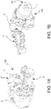
figures 1A-1B are perspective views of an electro-hydraulic actuator for hydraulic brakes according to the invention; -
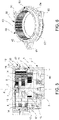
figure 2 is a section view taken along a longitudinal axis and enlarged of a portion of the actuator infigures 1A-1B according to a first embodiment of the invention; -
figure 3 is a perspective view of a portion of a reduction gear of the actuator infigure 2 ; -
figure 4 is a perspective view of a crown with inner toothing of the reduction gear offigures 2 and3 according to the first embodiment; -
figure 5 is a section view taken along a longitudinal axis and enlarged of a portion of the actuator of the invention according to a second embodiment; -
figure 6 is a perspective view of a crown with inner toothing of the reduction gear offigure 5 according to the second example of embodiment of the invention. - Similar or equivalent elements in the aforesaid figures will be indicated by means of the same reference numerals.
- An electro-hydraulic actuator according to the invention is shown in the figures and indicated by
reference numeral 100 as a whole. - Such an electro-
hydraulic actuator 100, or simply actuator, is configured for actuating a brake caliper of the disc brake with a hydraulic thrust assembly. Theactuator 100 comprises an electric motor 1 with a drive shaft 2, atransforming mechanism 3 connected to the drive shaft 2 and adapted to transform a rotary motion of the motor shaft 2 into a translational motion of a movable portion of the actuator housed in aportion 4 of theactuator 100 which extends from theactuator 100 orthogonally to the drive shaft 2. - In particular, a hydraulic pump (not shown in the figures) is operatively associated with the
motion transforming mechanism 3 to perform an increase in the hydraulic fluid pressure in response to said translational movement. - With reference to
figures 1A, 1B ,2 ,5 , theactuator 100 comprises afirst housing 5 configured to accommodate the transformingmechanism 3 and to support asecond housing 21 of the electric motor 1. - With reference to the embodiments in
figures 2 and5 , in greater detail, the transformingmechanism 3 includes amotion reduction gear - Such a
reduction gear crown - In an example of embodiment, the
reduction gear first reduction portion 10 operatively associated with thecrown first reduction portion 10 includes a first and a second reduction stage. - Furthermore, the
epicyclic reduction gear 6; 36 comprises asecond reduction portion 11, which includes a third reduction stage. - It is worth noting that the transforming
mechanism 3 comprises transmission means 7 of the rotary motion of the drive shaft 2 to theepicyclic reduction gear - According to an embodiment of the invention, said transmission means 7 comprise a connecting portion formed on the end of the motor shaft 2 having an external toothing which meshes
planet gears 9 of a first set of planet gears of theepicyclic reduction gear first reduction portion 10 of theepicyclic reducer - The
first reduction portion 10, which comprises the first reduction stage, includes the aforesaid central pinion formed by the end of the drive shaft 2, the first set ofplanet gears 9 supported by a firstplanet carrier plate 13 and thecrown aforesaid planet gears 9 mesh both the drive shaft 2 and thecrown - The aforesaid first
planet carrier plate 13 comprises, in turn, a central toothed portion which constitutes a central pinion (sun gear) of a second reduction stage of thefirst reduction portion 10. - Such a second reduction stage comprises, in addition to the second central pinion (sun gear) formed by the central toothed portion of the first
planet carrier plate 13, thetoothed crown planet gears 14 which mesh with both the second central pinion and thecrown - Such
second planet gears 14 are supported by a secondplanet carrier plate 15 which forms the connection to thesecond reduction portion 11. - As shown in
figures 2 and5 , thereduction gear first reduction portion 10. - The
second reduction portion 11 includes, for example, the third reduction stage similar to the aforesaid first and second reduction stage and includes a third set ofplanet gears 16 which mesh with a respective central pinion of theplanet carrier plate 15 and afurther crown 17. - As known to a person skilled in the art, two different sets of toothing are used as a function of the loads in the
reduction gear - According to an advantageous example of the present invention, the
crown front portion second housing 21 of the electric motor 1 and a rigid connection with thefirst housing 5 of thetransforming mechanism 3. - In such a manner, the rotation axis of the electric motor coincides with the central rotation axis X of the
reduction gear - With reference to
figure 2 ,3, 4 , in a first example embodiment of the invention, the aforesaid integral connection is directly shape-coupled to and inserted between arear portion 43 of thecrown 12 with inner toothing of thereduction gear 6 and thefirst housing 5 of thetransforming mechanism 3. - In a particular embodiment, such a
crown 12 with inner toothing is made of steel. The number of teeth is, for example, comprised in the range from seventy to ninety teeth. - With reference to
figures 5, 6 , in a second example embodiment of the invention, the aforesaid integral connection is made by continuity of material, wherein thecrown 32 with inner toothing and thefirst housing 5, 5' are in one piece. - In particular, the
crown 32 is in one piece with a portion 5' of thefirst housing 5 of the transformingmechanism 3. - With reference to
figure 6 , such acrown 32 with inner toothing comprisesrespective fastening seats 65, in particular at least three seats, having radial development configured to be engaged by respective screws for fixing thecrown 32 to thefirst housing 5 of the transforming mechanism. - Furthermore, the
crown 32 comprises acircular crown wall 66 which develops orthogonally to the main longitudinal axis of thecrown 32 configured to separate thefirst reduction portion 10 from thesecond reduction portion 11. - In a particular embodiment, the
crown 32 with internal toothing of thegear reducer 36 is made of thermoplastic polymeric material. The number of teeth is, for example, comprised in the range from seventy to ninety teeth. - In an example embodiment of the actuator of the invention, the
crown crown first housing 5 of the transformingmechanism 3 and/or with respect to thesecond housing 21 of the electric motor 1. - With reference to
figure 4 , in a first example of the invention, the aforesaid means for preventing the rotation of thecrown 12 with inner toothing comprise a knurled band 44 provided on an outercircumferential surface 45 of the crown adapted to interfere with thefirst housing 5 of the transformingmechanism 3. - With reference to
figure 6 , in a second example of the invention, the aforesaid means for preventing the rotation of thecrown 32 with inner toothing comprise the aforementioned at least three fixingseats 65 protruding from a circumferentialexternal surface 64 of thecrown 32. - In a particularly advantageous example embodiment, the
crown 32 with internal toothing of thereduction gear 36 comprises at least threerecesses 63, in the example equally spaced apart from one another by 120°, along an edge of thefront portion 62 of the crown.Such recesses 63 are configured to promote the centering of motor shim (not shown in the figures) with thesecond housing 21 of electric motor 1. - It is worth noting that the
circular crown wall 66 which extends at right angles to the main longitudinal axis of thecrown 32 is opposed to the aforesaidfront portion edge 62 of the crown. - The present invention also relates to the single brake that comprises the electro-
hydraulic actuator 100 for powering the hydraulic thrust assembly. - It is worth noting that the outer part of the
crown 12 of theactuator 100 of the invention ensures the centering towards thehousing 5 of the transmission ensuring the interference and also the correct mounting of O-rings 40, 50 between thetransmission housing 3 and the engine housing. - Moreover, the crown with
inner toothing first reduction portion 10.
Claims (12)
- An electro-hydraulic actuator (100) for actuating a brake caliper, in particular a disc brake of a vehicle with two or more wheels, comprising:- an electric motor (1) with a drive shaft (2);- a transforming mechanism (3) connected to the drive shaft (2) to transform a rotary motion of the drive shaft (2) into a translational motion of a translatable portion (4) configured to act on a hydraulic master cylinder of said brake;- a first housing (5) configured to accommodate the transforming mechanism (3) and support a second housing (21) of the electric motor (1), said transforming mechanism including a reduction gear (6; 36) configured to demultiply the rotary motion of the drive shaft (2), said reduction gear (6; 36) comprising a crown (12; 32) with inner toothing in one piece and rotationally locked,characterized in that
said crown (12; 32) with inner toothing comprises a front portion (42; 62) directly shape-coupled to and inserted in the second housing (21) of the electric motor (1) and a connection integral with the first housing (5) of the transforming mechanism (3) so as to achieve a precise centering between the electric motor (1) and the reduction gear (6; 36) with respect to the axis of the drive shaft (2) and with respect to a central axis (X) of the reduction gear (6; 36). - An electro-hydraulic actuator (100) according to claim 1, wherein said integral connection is directly shape-coupled to and inserted between a rear portion (43) of the crown (12) with inner toothing and the first housing (5) of the transforming mechanism (3) .
- An electro-hydraulic actuator (100) according to claim 1, wherein said integral connection is made by continuity of material wherein the crown (32) with inner toothing and the first housing are in one piece.
- An electro-hydraulic actuator (100) according to claim 2, wherein said crown (12) with inner toothing is made of steel.
- An electro-hydraulic actuator (100) according to claim 3, wherein said crown (32) with inner toothing is made of thermoplastic polymer material.
- An electro-hydraulic actuator (100) according to claim 1, wherein said crown (12; 32) with inner toothing comprises means (44; 65) adapted to prevent the rotation of the crown with respect to the first housing (5) of the transforming mechanism (3) and/or with respect to the second housing (21) of the electric motor (1).
- An electro-hydraulic actuator (100) according to claim 6, wherein said means for preventing the rotation of the crown (12) with inner toothing comprise a knurled band (44) provided on an outer circumferential surface (45) of the crown adapted to interfere with the first housing (5) of the transforming mechanism (3) .
- An electro-hydraulic actuator (100) according to claim 6, wherein said means for preventing the rotation of the crown (32) with inner toothing comprise at least three fastening seats (65) protruding from an outer circumferential surface (64) of the crown, said fastening seats being configured to be engaged by respective screws for fixing the crown (32) with inner toothing to the first housing (5) of the transforming mechanism.
- An electro-hydraulic actuator (100) according to claim 1, wherein said crown (32) with inner toothing comprises at least three recesses (63) provided along an edge of the front portion (62) of the crown.
- An electro-hydraulic actuator (100) according to claim 1, wherein said reduction gear (6; 36) is epicyclic and comprises a first reduction portion (10), which includes a first and a second reduction stage, operatively associated with said crown (12; 32) with inner toothing.
- An electro-hydraulic actuator (100) according to claim 10, wherein said epicyclic reduction gear (6; 36) comprises a second reduction portion (11), which includes a third reduction stage.
- A hydraulic brake for a vehicle, comprising a hydraulic thrust unit and an electro-hydraulic actuator (100) according to any one of the preceding claims.
Applications Claiming Priority (2)
| Application Number | Priority Date | Filing Date | Title |
|---|---|---|---|
| IT102018000005888A IT201800005888A1 (en) | 2018-05-31 | 2018-05-31 | PERFECTED ELECTRO-HYDRAULIC ACTUATOR FOR BRAKE |
| PCT/IB2019/054324 WO2019229604A1 (en) | 2018-05-31 | 2019-05-24 | Improved electro-hydraulic actuator for brake |
Publications (2)
| Publication Number | Publication Date |
|---|---|
| EP3802248A1 EP3802248A1 (en) | 2021-04-14 |
| EP3802248B1 true EP3802248B1 (en) | 2022-12-28 |
Family
ID=63312349
Family Applications (1)
| Application Number | Title | Priority Date | Filing Date |
|---|---|---|---|
| EP19732132.6A Active EP3802248B1 (en) | 2018-05-31 | 2019-05-24 | Improved electro-hydraulic actuator for brake |
Country Status (6)
| Country | Link |
|---|---|
| US (1) | US12084017B2 (en) |
| EP (1) | EP3802248B1 (en) |
| JP (1) | JP7320171B2 (en) |
| CN (1) | CN112543721A (en) |
| IT (1) | IT201800005888A1 (en) |
| WO (1) | WO2019229604A1 (en) |
Cited By (1)
| Publication number | Priority date | Publication date | Assignee | Title |
|---|---|---|---|---|
| WO2025218878A1 (en) * | 2024-04-15 | 2025-10-23 | Johnson Electric International AG | Multi-stage planetary gear assembly |
Families Citing this family (2)
| Publication number | Priority date | Publication date | Assignee | Title |
|---|---|---|---|---|
| US12421692B2 (en) * | 2022-05-11 | 2025-09-23 | Caterpillar Inc. | House swing sensor follower pinion |
| USD1062817S1 (en) * | 2022-07-25 | 2025-02-18 | Parker-Hannifin Corporation | Actuator |
Citations (2)
| Publication number | Priority date | Publication date | Assignee | Title |
|---|---|---|---|---|
| EP1021664B1 (en) * | 1997-10-07 | 2002-01-09 | Interroll Holding AG | A drum motor |
| EP2395262B1 (en) * | 2010-06-11 | 2013-04-03 | Nice S.P.A. | Epicyclic gearbox for tubular motors |
Family Cites Families (27)
| Publication number | Priority date | Publication date | Assignee | Title |
|---|---|---|---|---|
| US4016779A (en) * | 1975-04-04 | 1977-04-12 | Von Greyerz John W | Worm drive automatic transmission |
| JPS63214546A (en) * | 1987-02-28 | 1988-09-07 | Sayama Seimitsu Kogyo Kk | Unit mechanism for epicyclic reduction gear |
| JPH0781614B2 (en) * | 1989-07-11 | 1995-09-06 | マテツクス株式会社 | Connection structure of planetary gear unit |
| DE19521634A1 (en) * | 1995-06-14 | 1996-12-19 | Teves Gmbh Alfred | Disc brake with automatic adjustment device |
| NL1007296C2 (en) * | 1997-10-16 | 1999-04-19 | Skf Ind Trading & Dev | Modular actuator, as well as caliper with such an actuator. |
| WO1999037010A1 (en) * | 1998-01-20 | 1999-07-22 | Skf Engineering & Research Centre B.V. | Modular actuator, and brake calliper comprising such actuator |
| US7854995B1 (en) * | 2004-07-14 | 2010-12-21 | Keystone Investment Corporation | High density dual helical gear |
| DE102005055085B4 (en) * | 2005-09-29 | 2020-09-24 | Robert Bosch Gmbh | Combined service and parking brake device as well as a method for performing emergency braking |
| WO2007064330A1 (en) * | 2005-12-02 | 2007-06-07 | United Technologies Corporation | Gear having improved surface finish |
| CN201041210Y (en) * | 2007-06-08 | 2008-03-26 | 江苏大学 | An electronic mechanical brake device for a vehicle |
| DE102009060201A1 (en) * | 2009-12-23 | 2011-06-30 | Lucas Automotive GmbH, 56070 | Subassembly for an electromechanical brake actuator |
| DE102011102860B4 (en) * | 2011-05-31 | 2022-12-22 | Zf Active Safety Gmbh | Electromechanically actuated motor vehicle brake with optional self-locking |
| ITMI20120220A1 (en) * | 2012-02-15 | 2013-08-16 | Freni Brembo Spa | ELECTRIC PARKING BRAKE |
| ITMI20120812A1 (en) * | 2012-05-11 | 2013-11-12 | Freni Brembo Spa | ELECTRO-HYDRAULIC BRAKE ACTUATOR |
| KR101607086B1 (en) * | 2012-06-29 | 2016-03-30 | 주식회사 만도 | Electric mechanical brake system |
| CH707435A1 (en) * | 2013-01-09 | 2014-07-15 | Thyssenkrupp Presta Ag | Angle superimposition device for a vehicle steering apparatus with a planetary gear. |
| CN104806668A (en) * | 2014-01-27 | 2015-07-29 | 德昌电机(深圳)有限公司 | Executor of electric parking brake system |
| FR3017173A1 (en) * | 2014-01-31 | 2015-08-07 | Bosch Gmbh Robert | TRANSMISSION DEVICE FOR CONTROLLING THE ORGANIZATION TRANSLATION MOTION AND BRAKE SYSTEM EQUIPPED WITH SUCH A TRANSMISSION DEVICE FORMING A SERVOFREIN |
| DE102014212409A1 (en) * | 2014-06-27 | 2015-12-31 | Robert Bosch Gmbh | Pressure generator for a hydraulic vehicle brake system |
| US9925968B2 (en) * | 2015-05-18 | 2018-03-27 | Beijingwest Industries Co., Ltd. | Brake booster assembly |
| DE102015214584B4 (en) * | 2015-07-31 | 2024-11-07 | Robert Bosch Gmbh | rotational/translational converter transmission |
| DE102015223507A1 (en) * | 2015-11-27 | 2017-06-01 | Robert Bosch Gmbh | Piston pump unit |
| JP6682316B2 (en) * | 2016-03-29 | 2020-04-15 | Ntn株式会社 | Electric actuator |
| US11152840B2 (en) * | 2016-03-30 | 2021-10-19 | Ntn Corporation | Electric actuator |
| JP2018044636A (en) * | 2016-09-15 | 2018-03-22 | Ntn株式会社 | Electric actuator |
| EP3486527B1 (en) * | 2017-11-17 | 2020-07-08 | IMS Gear SE & Co. KGaA | Crossed-axes planet gear and internal crossed-axes gear for a crossed-axes planet gear |
| US11287002B1 (en) * | 2020-12-23 | 2022-03-29 | Hyo Seong America Corporation | Electric brake actuator |
-
2018
- 2018-05-31 IT IT102018000005888A patent/IT201800005888A1/en unknown
-
2019
- 2019-05-24 JP JP2020566783A patent/JP7320171B2/en active Active
- 2019-05-24 WO PCT/IB2019/054324 patent/WO2019229604A1/en not_active Ceased
- 2019-05-24 US US17/059,695 patent/US12084017B2/en active Active
- 2019-05-24 EP EP19732132.6A patent/EP3802248B1/en active Active
- 2019-05-24 CN CN201980046822.4A patent/CN112543721A/en active Pending
Patent Citations (2)
| Publication number | Priority date | Publication date | Assignee | Title |
|---|---|---|---|---|
| EP1021664B1 (en) * | 1997-10-07 | 2002-01-09 | Interroll Holding AG | A drum motor |
| EP2395262B1 (en) * | 2010-06-11 | 2013-04-03 | Nice S.P.A. | Epicyclic gearbox for tubular motors |
Cited By (1)
| Publication number | Priority date | Publication date | Assignee | Title |
|---|---|---|---|---|
| WO2025218878A1 (en) * | 2024-04-15 | 2025-10-23 | Johnson Electric International AG | Multi-stage planetary gear assembly |
Also Published As
| Publication number | Publication date |
|---|---|
| CN112543721A (en) | 2021-03-23 |
| JP2021526100A (en) | 2021-09-30 |
| US20210197782A1 (en) | 2021-07-01 |
| EP3802248A1 (en) | 2021-04-14 |
| WO2019229604A1 (en) | 2019-12-05 |
| US12084017B2 (en) | 2024-09-10 |
| JP7320171B2 (en) | 2023-08-03 |
| IT201800005888A1 (en) | 2019-12-01 |
Similar Documents
| Publication | Publication Date | Title |
|---|---|---|
| JP6562496B2 (en) | Actuator for electric parking brake system | |
| EP3802248B1 (en) | Improved electro-hydraulic actuator for brake | |
| US9689443B2 (en) | Electric parking brake driving device and electric parking brake device | |
| CN108105293B (en) | Brake actuators, automotive braking systems and electric vehicles | |
| CN103032498A (en) | Disk brake apparatus | |
| JP2012007674A (en) | Disc brake | |
| JP2022543003A (en) | Hydraulic and electromechanical service & parking disc brakes | |
| CN106949169B (en) | Electronic disc brake | |
| US12139116B2 (en) | Disk brake | |
| US12168427B2 (en) | Reduction gearbox for drum brake, offering significant conformability | |
| CN114043975B (en) | Braking force amplifying device, braking system and vehicle | |
| CN109311468B (en) | Actuating device for vehicle brakes | |
| KR102672342B1 (en) | Electro-mechanical brake system | |
| KR102858443B1 (en) | Electromechanical driven brake pressure generator | |
| WO2020110823A1 (en) | Disc brake | |
| EP2183502B1 (en) | Actuator for parking brake | |
| CN108290564B (en) | Electromechanical brake booster | |
| KR20240167668A (en) | Linear operating device of brake caliper and brake caliper having said device | |
| US12221083B2 (en) | Reduction motor for drum brake | |
| KR20230133139A (en) | Electronic parking brake | |
| EP4242486B1 (en) | Brake apparatus for vehicle | |
| JP2020029866A (en) | Rotary-to-linear conversion mechanism and electric booster | |
| JP2025519132A (en) | Drive unit for an operating device of a brake system, operating device | |
| CN116123232A (en) | Novel motor vehicle parking actuator | |
| WO2018139163A1 (en) | Disc brake |
Legal Events
| Date | Code | Title | Description |
|---|---|---|---|
| STAA | Information on the status of an ep patent application or granted ep patent |
Free format text: STATUS: UNKNOWN |
|
| STAA | Information on the status of an ep patent application or granted ep patent |
Free format text: STATUS: THE INTERNATIONAL PUBLICATION HAS BEEN MADE |
|
| PUAI | Public reference made under article 153(3) epc to a published international application that has entered the european phase |
Free format text: ORIGINAL CODE: 0009012 |
|
| STAA | Information on the status of an ep patent application or granted ep patent |
Free format text: STATUS: REQUEST FOR EXAMINATION WAS MADE |
|
| 17P | Request for examination filed |
Effective date: 20201130 |
|
| AK | Designated contracting states |
Kind code of ref document: A1 Designated state(s): AL AT BE BG CH CY CZ DE DK EE ES FI FR GB GR HR HU IE IS IT LI LT LU LV MC MK MT NL NO PL PT RO RS SE SI SK SM TR |
|
| AX | Request for extension of the european patent |
Extension state: BA ME |
|
| RAP3 | Party data changed (applicant data changed or rights of an application transferred) |
Owner name: BREMBO S.P.A. |
|
| RIN1 | Information on inventor provided before grant (corrected) |
Inventor name: CARRARA, MARCO Inventor name: SALA, PAOLO |
|
| RAP3 | Party data changed (applicant data changed or rights of an application transferred) |
Owner name: BREMBO S.P.A. |
|
| DAV | Request for validation of the european patent (deleted) | ||
| DAX | Request for extension of the european patent (deleted) | ||
| GRAP | Despatch of communication of intention to grant a patent |
Free format text: ORIGINAL CODE: EPIDOSNIGR1 |
|
| STAA | Information on the status of an ep patent application or granted ep patent |
Free format text: STATUS: GRANT OF PATENT IS INTENDED |
|
| INTG | Intention to grant announced |
Effective date: 20220830 |
|
| RIN1 | Information on inventor provided before grant (corrected) |
Inventor name: SALA, PAOLO Inventor name: CARRARA, MARCO |
|
| GRAS | Grant fee paid |
Free format text: ORIGINAL CODE: EPIDOSNIGR3 |
|
| GRAA | (expected) grant |
Free format text: ORIGINAL CODE: 0009210 |
|
| STAA | Information on the status of an ep patent application or granted ep patent |
Free format text: STATUS: THE PATENT HAS BEEN GRANTED |
|
| AK | Designated contracting states |
Kind code of ref document: B1 Designated state(s): AL AT BE BG CH CY CZ DE DK EE ES FI FR GB GR HR HU IE IS IT LI LT LU LV MC MK MT NL NO PL PT RO RS SE SI SK SM TR |
|
| REG | Reference to a national code |
Ref country code: GB Ref legal event code: FG4D |
|
| REG | Reference to a national code |
Ref country code: CH Ref legal event code: EP |
|
| REG | Reference to a national code |
Ref country code: DE Ref legal event code: R096 Ref document number: 602019023686 Country of ref document: DE |
|
| REG | Reference to a national code |
Ref country code: AT Ref legal event code: REF Ref document number: 1540297 Country of ref document: AT Kind code of ref document: T Effective date: 20230115 |
|
| REG | Reference to a national code |
Ref country code: IE Ref legal event code: FG4D |
|
| REG | Reference to a national code |
Ref country code: LT Ref legal event code: MG9D |
|
| PG25 | Lapsed in a contracting state [announced via postgrant information from national office to epo] |
Ref country code: SE Free format text: LAPSE BECAUSE OF FAILURE TO SUBMIT A TRANSLATION OF THE DESCRIPTION OR TO PAY THE FEE WITHIN THE PRESCRIBED TIME-LIMIT Effective date: 20221228 Ref country code: NO Free format text: LAPSE BECAUSE OF FAILURE TO SUBMIT A TRANSLATION OF THE DESCRIPTION OR TO PAY THE FEE WITHIN THE PRESCRIBED TIME-LIMIT Effective date: 20230328 Ref country code: LT Free format text: LAPSE BECAUSE OF FAILURE TO SUBMIT A TRANSLATION OF THE DESCRIPTION OR TO PAY THE FEE WITHIN THE PRESCRIBED TIME-LIMIT Effective date: 20221228 Ref country code: FI Free format text: LAPSE BECAUSE OF FAILURE TO SUBMIT A TRANSLATION OF THE DESCRIPTION OR TO PAY THE FEE WITHIN THE PRESCRIBED TIME-LIMIT Effective date: 20221228 |
|
| REG | Reference to a national code |
Ref country code: NL Ref legal event code: MP Effective date: 20221228 |
|
| REG | Reference to a national code |
Ref country code: AT Ref legal event code: MK05 Ref document number: 1540297 Country of ref document: AT Kind code of ref document: T Effective date: 20221228 |
|
| PG25 | Lapsed in a contracting state [announced via postgrant information from national office to epo] |
Ref country code: RS Free format text: LAPSE BECAUSE OF FAILURE TO SUBMIT A TRANSLATION OF THE DESCRIPTION OR TO PAY THE FEE WITHIN THE PRESCRIBED TIME-LIMIT Effective date: 20221228 Ref country code: LV Free format text: LAPSE BECAUSE OF FAILURE TO SUBMIT A TRANSLATION OF THE DESCRIPTION OR TO PAY THE FEE WITHIN THE PRESCRIBED TIME-LIMIT Effective date: 20221228 Ref country code: HR Free format text: LAPSE BECAUSE OF FAILURE TO SUBMIT A TRANSLATION OF THE DESCRIPTION OR TO PAY THE FEE WITHIN THE PRESCRIBED TIME-LIMIT Effective date: 20221228 Ref country code: GR Free format text: LAPSE BECAUSE OF FAILURE TO SUBMIT A TRANSLATION OF THE DESCRIPTION OR TO PAY THE FEE WITHIN THE PRESCRIBED TIME-LIMIT Effective date: 20230329 |
|
| PG25 | Lapsed in a contracting state [announced via postgrant information from national office to epo] |
Ref country code: NL Free format text: LAPSE BECAUSE OF FAILURE TO SUBMIT A TRANSLATION OF THE DESCRIPTION OR TO PAY THE FEE WITHIN THE PRESCRIBED TIME-LIMIT Effective date: 20221228 |
|
| P01 | Opt-out of the competence of the unified patent court (upc) registered |
Effective date: 20230526 |
|
| PG25 | Lapsed in a contracting state [announced via postgrant information from national office to epo] |
Ref country code: SM Free format text: LAPSE BECAUSE OF FAILURE TO SUBMIT A TRANSLATION OF THE DESCRIPTION OR TO PAY THE FEE WITHIN THE PRESCRIBED TIME-LIMIT Effective date: 20221228 Ref country code: RO Free format text: LAPSE BECAUSE OF FAILURE TO SUBMIT A TRANSLATION OF THE DESCRIPTION OR TO PAY THE FEE WITHIN THE PRESCRIBED TIME-LIMIT Effective date: 20221228 Ref country code: PT Free format text: LAPSE BECAUSE OF FAILURE TO SUBMIT A TRANSLATION OF THE DESCRIPTION OR TO PAY THE FEE WITHIN THE PRESCRIBED TIME-LIMIT Effective date: 20230428 Ref country code: ES Free format text: LAPSE BECAUSE OF FAILURE TO SUBMIT A TRANSLATION OF THE DESCRIPTION OR TO PAY THE FEE WITHIN THE PRESCRIBED TIME-LIMIT Effective date: 20221228 Ref country code: EE Free format text: LAPSE BECAUSE OF FAILURE TO SUBMIT A TRANSLATION OF THE DESCRIPTION OR TO PAY THE FEE WITHIN THE PRESCRIBED TIME-LIMIT Effective date: 20221228 Ref country code: CZ Free format text: LAPSE BECAUSE OF FAILURE TO SUBMIT A TRANSLATION OF THE DESCRIPTION OR TO PAY THE FEE WITHIN THE PRESCRIBED TIME-LIMIT Effective date: 20221228 Ref country code: AT Free format text: LAPSE BECAUSE OF FAILURE TO SUBMIT A TRANSLATION OF THE DESCRIPTION OR TO PAY THE FEE WITHIN THE PRESCRIBED TIME-LIMIT Effective date: 20221228 |
|
| PG25 | Lapsed in a contracting state [announced via postgrant information from national office to epo] |
Ref country code: SK Free format text: LAPSE BECAUSE OF FAILURE TO SUBMIT A TRANSLATION OF THE DESCRIPTION OR TO PAY THE FEE WITHIN THE PRESCRIBED TIME-LIMIT Effective date: 20221228 Ref country code: PL Free format text: LAPSE BECAUSE OF FAILURE TO SUBMIT A TRANSLATION OF THE DESCRIPTION OR TO PAY THE FEE WITHIN THE PRESCRIBED TIME-LIMIT Effective date: 20221228 Ref country code: IS Free format text: LAPSE BECAUSE OF FAILURE TO SUBMIT A TRANSLATION OF THE DESCRIPTION OR TO PAY THE FEE WITHIN THE PRESCRIBED TIME-LIMIT Effective date: 20230428 Ref country code: AL Free format text: LAPSE BECAUSE OF FAILURE TO SUBMIT A TRANSLATION OF THE DESCRIPTION OR TO PAY THE FEE WITHIN THE PRESCRIBED TIME-LIMIT Effective date: 20221228 |
|
| REG | Reference to a national code |
Ref country code: DE Ref legal event code: R097 Ref document number: 602019023686 Country of ref document: DE |
|
| PG25 | Lapsed in a contracting state [announced via postgrant information from national office to epo] |
Ref country code: DK Free format text: LAPSE BECAUSE OF FAILURE TO SUBMIT A TRANSLATION OF THE DESCRIPTION OR TO PAY THE FEE WITHIN THE PRESCRIBED TIME-LIMIT Effective date: 20221228 |
|
| PLBE | No opposition filed within time limit |
Free format text: ORIGINAL CODE: 0009261 |
|
| STAA | Information on the status of an ep patent application or granted ep patent |
Free format text: STATUS: NO OPPOSITION FILED WITHIN TIME LIMIT |
|
| 26N | No opposition filed |
Effective date: 20230929 |
|
| REG | Reference to a national code |
Ref country code: CH Ref legal event code: PL |
|
| PG25 | Lapsed in a contracting state [announced via postgrant information from national office to epo] |
Ref country code: MC Free format text: LAPSE BECAUSE OF FAILURE TO SUBMIT A TRANSLATION OF THE DESCRIPTION OR TO PAY THE FEE WITHIN THE PRESCRIBED TIME-LIMIT Effective date: 20221228 |
|
| REG | Reference to a national code |
Ref country code: BE Ref legal event code: MM Effective date: 20230531 |
|
| PG25 | Lapsed in a contracting state [announced via postgrant information from national office to epo] |
Ref country code: SI Free format text: LAPSE BECAUSE OF FAILURE TO SUBMIT A TRANSLATION OF THE DESCRIPTION OR TO PAY THE FEE WITHIN THE PRESCRIBED TIME-LIMIT Effective date: 20221228 Ref country code: MC Free format text: LAPSE BECAUSE OF FAILURE TO SUBMIT A TRANSLATION OF THE DESCRIPTION OR TO PAY THE FEE WITHIN THE PRESCRIBED TIME-LIMIT Effective date: 20221228 Ref country code: LU Free format text: LAPSE BECAUSE OF NON-PAYMENT OF DUE FEES Effective date: 20230524 Ref country code: LI Free format text: LAPSE BECAUSE OF NON-PAYMENT OF DUE FEES Effective date: 20230531 Ref country code: CH Free format text: LAPSE BECAUSE OF NON-PAYMENT OF DUE FEES Effective date: 20230531 |
|
| REG | Reference to a national code |
Ref country code: IE Ref legal event code: MM4A |
|
| PG25 | Lapsed in a contracting state [announced via postgrant information from national office to epo] |
Ref country code: IE Free format text: LAPSE BECAUSE OF NON-PAYMENT OF DUE FEES Effective date: 20230524 |
|
| PG25 | Lapsed in a contracting state [announced via postgrant information from national office to epo] |
Ref country code: IE Free format text: LAPSE BECAUSE OF NON-PAYMENT OF DUE FEES Effective date: 20230524 |
|
| PG25 | Lapsed in a contracting state [announced via postgrant information from national office to epo] |
Ref country code: BE Free format text: LAPSE BECAUSE OF NON-PAYMENT OF DUE FEES Effective date: 20230531 |
|
| PG25 | Lapsed in a contracting state [announced via postgrant information from national office to epo] |
Ref country code: BG Free format text: LAPSE BECAUSE OF FAILURE TO SUBMIT A TRANSLATION OF THE DESCRIPTION OR TO PAY THE FEE WITHIN THE PRESCRIBED TIME-LIMIT Effective date: 20221228 |
|
| PG25 | Lapsed in a contracting state [announced via postgrant information from national office to epo] |
Ref country code: BG Free format text: LAPSE BECAUSE OF FAILURE TO SUBMIT A TRANSLATION OF THE DESCRIPTION OR TO PAY THE FEE WITHIN THE PRESCRIBED TIME-LIMIT Effective date: 20221228 |
|
| PGFP | Annual fee paid to national office [announced via postgrant information from national office to epo] |
Ref country code: DE Payment date: 20250523 Year of fee payment: 7 |
|
| PGFP | Annual fee paid to national office [announced via postgrant information from national office to epo] |
Ref country code: GB Payment date: 20250527 Year of fee payment: 7 |
|
| PGFP | Annual fee paid to national office [announced via postgrant information from national office to epo] |
Ref country code: FR Payment date: 20250430 Year of fee payment: 7 |
|
| PG25 | Lapsed in a contracting state [announced via postgrant information from national office to epo] |
Ref country code: CY Free format text: LAPSE BECAUSE OF FAILURE TO SUBMIT A TRANSLATION OF THE DESCRIPTION OR TO PAY THE FEE WITHIN THE PRESCRIBED TIME-LIMIT; INVALID AB INITIO Effective date: 20190524 |
|
| PG25 | Lapsed in a contracting state [announced via postgrant information from national office to epo] |
Ref country code: HU Free format text: LAPSE BECAUSE OF FAILURE TO SUBMIT A TRANSLATION OF THE DESCRIPTION OR TO PAY THE FEE WITHIN THE PRESCRIBED TIME-LIMIT; INVALID AB INITIO Effective date: 20190524 |
|
| PG25 | Lapsed in a contracting state [announced via postgrant information from national office to epo] |
Ref country code: TR Free format text: LAPSE BECAUSE OF FAILURE TO SUBMIT A TRANSLATION OF THE DESCRIPTION OR TO PAY THE FEE WITHIN THE PRESCRIBED TIME-LIMIT Effective date: 20221228 |
|
| PGFP | Annual fee paid to national office [announced via postgrant information from national office to epo] |
Ref country code: IT Payment date: 20260325 Year of fee payment: 8 |