EP3802017B1 - Autonom verkapselndes greifwerkzeug - Google Patents
Autonom verkapselndes greifwerkzeug Download PDFInfo
- Publication number
- EP3802017B1 EP3802017B1 EP19814924.7A EP19814924A EP3802017B1 EP 3802017 B1 EP3802017 B1 EP 3802017B1 EP 19814924 A EP19814924 A EP 19814924A EP 3802017 B1 EP3802017 B1 EP 3802017B1
- Authority
- EP
- European Patent Office
- Prior art keywords
- workpiece
- base
- segment
- tendon
- tooling
- Prior art date
- Legal status (The legal status is an assumption and is not a legal conclusion. Google has not performed a legal analysis and makes no representation as to the accuracy of the status listed.)
- Active
Links
Images







Classifications
-
- B—PERFORMING OPERATIONS; TRANSPORTING
- B25—HAND TOOLS; PORTABLE POWER-DRIVEN TOOLS; MANIPULATORS
- B25J—MANIPULATORS; CHAMBERS PROVIDED WITH MANIPULATION DEVICES
- B25J15/00—Gripping heads and other end effectors
- B25J15/0009—Gripping heads and other end effectors comprising multi-articulated fingers, e.g. resembling a human hand
-
- B—PERFORMING OPERATIONS; TRANSPORTING
- B25—HAND TOOLS; PORTABLE POWER-DRIVEN TOOLS; MANIPULATORS
- B25J—MANIPULATORS; CHAMBERS PROVIDED WITH MANIPULATION DEVICES
- B25J15/00—Gripping heads and other end effectors
- B25J15/02—Gripping heads and other end effectors servo-actuated
- B25J15/0206—Gripping heads and other end effectors servo-actuated comprising articulated grippers
- B25J15/0233—Gripping heads and other end effectors servo-actuated comprising articulated grippers actuated by chains, cables or ribbons
-
- B—PERFORMING OPERATIONS; TRANSPORTING
- B25—HAND TOOLS; PORTABLE POWER-DRIVEN TOOLS; MANIPULATORS
- B25J—MANIPULATORS; CHAMBERS PROVIDED WITH MANIPULATION DEVICES
- B25J15/00—Gripping heads and other end effectors
- B25J15/02—Gripping heads and other end effectors servo-actuated
- B25J15/0253—Gripping heads and other end effectors servo-actuated comprising parallel grippers
-
- B—PERFORMING OPERATIONS; TRANSPORTING
- B25—HAND TOOLS; PORTABLE POWER-DRIVEN TOOLS; MANIPULATORS
- B25J—MANIPULATORS; CHAMBERS PROVIDED WITH MANIPULATION DEVICES
- B25J15/00—Gripping heads and other end effectors
- B25J15/08—Gripping heads and other end effectors having finger members
- B25J15/10—Gripping heads and other end effectors having finger members with three or more finger members
-
- B—PERFORMING OPERATIONS; TRANSPORTING
- B25—HAND TOOLS; PORTABLE POWER-DRIVEN TOOLS; MANIPULATORS
- B25J—MANIPULATORS; CHAMBERS PROVIDED WITH MANIPULATION DEVICES
- B25J9/00—Program-controlled manipulators
- B25J9/10—Program-controlled manipulators characterised by positioning means for manipulator elements
- B25J9/104—Program-controlled manipulators characterised by positioning means for manipulator elements with cables, chains or ribbons
Definitions
- the present invention relates to gripper tooling, and, more particularly, to self-articulating grippers.
- Grippers are mechanical devices which generally include jaws that are moved together or apart by motive devices, such as electric motors or pneumatic pistons.
- Tooling is typically fastened to the jaw to provide some degree of conformal contact between the surface of the tool and one or more surfaces of a gripped workpiece.
- the jaws Once the jaws have moved the fastened tooling into a position of contact with the gripped workpiece, the jaws produce a force against the tooling which is transferred by the tooling to retain the workpiece so that the position of the workpiece might be subsequently translated or rotated. It is often desirable that the tooling fully or partially encapsulate the profile of the workpiece to prevent relative motion from occurring between the workpiece and tooling as the workpiece is subsequently translated or rotated or external forces are applied to the workpiece.
- US 2017/252930 A1 discloses a mechanical finger having a base adapted to be connected to an actuator for being displaced in at least one degree of actuation, and two or more phalanges.
- JP 2001 277174 A discloses a multitude of link bars that are sequentially interconnected from a link base to provide a multi-nodal link row. A slide shaft engaged with a shaft hole in the link base is fixed to a substrate, and tension springs are hung over both sides of the link base.
- Document JP2010253571A discloses another document with a swinging mechanism that improves the gripping action.
- the present invention provides a gripper tooling capable of autonomously adjusting to conform to the gripped profile of the workpiece, so as to encapsulate a broad spectrum of shapes and sizes of workpieces.
- the gripper tooling furthermore derives the motive force necessary to adjust solely from the motion of the gripper jaws to which the tooling is attached. This manner of force derivation simplifies the connection between the tooling and the gripper as the tooling need only to be mechanically fastened to the gripper in order to operate as desired.
- Such manner of simple attachment allows the tooling to be used with numerous types of commercial grippers by only changing the mounting pattern of the tooling to match the pattern of the gripper jaws.
- the invention in one form is directed to a gripper tooling including a gripper having a gripper body and at least one jaw connected and linearly sliding relative to the gripper body, at least one slider connected to the at least one jaw, and at least one tooling member configured for gripping a workpiece.
- Each tooling member including a base slideably mounted to the at least one slider, at least one middle segment pivotally connected to the base, a distal segment pivotally connected to the at least one middle segment, an adducting tendon having a proximal end attached to the at least one slider and a distal end attached to the distal segment, and an abducting tendon having a proximal end attached to the base and a distal end attached to the distal segment.
- the at least one tooling member is configured for autonomously gripping the workpiece as the at least one jaw moves toward the workpiece and the at least one tooling member autonomously returns to an ungripped position as the at least one jaw moves away from the workpiece.
- the invention in another form is directed to a gripper tooling including a gripper having a gripper body and at least one angular jaw, at least one rotor rotatably connected to the at least one angular jaw, and at least one tooling member configured for gripping a workpiece.
- Each tooling member including a base pivotally connected to the at least one rotor, at least one middle segment pivotally connected to the base, a distal segment pivotally connected to the at least one middle segment, an adducting tendon having a proximal end attached to the at least one rotor and a distal end attached to the distal segment, and an abducting tendon having a proximal end attached to the base and a distal end attached to the distal segment.
- the at least one tooling member is configured for autonomously gripping the workpiece as the at least one angular jaw rotates toward the workpiece and the at least one tooling member autonomously returns to an ungripped position as the at least one angular jaw rotates away from the workpiece.
- the invention in yet another form is directed to a method for gripping a workpiece including a step of providing a gripper tooling including a gripper having a gripper body and at least one jaw moveably connected to the gripper body, at least one mount moveably connected to the at least one jaw, and at least one tooling member configured for gripping the workpiece, each tooling member including a base moveably mounted to the at least one mount, at least one middle segment pivotally connected to the base, a distal segment pivotally connected to the at least one middle segment, an adducting tendon having a proximal end attached to the at least one mount and a distal end attached to the distal segment, and an abducting tendon having a proximal end attached to the base and a distal end attached to the distal segment.
- the method also includes the steps of gripping the workpiece by the adducting tendon upon moving the base, by the at least one jaw, to be immobilized by the workpiece, and ungripping the workpiece by the abducting tendon upon moving the base, by the at least one jaw, away from the workpiece.
- An advantage of the present invention is that the gripper tooling fingers self-articulate, via the usual operational motion of the gripper jaws, to autonomously encapsulate a plethora of differently-shaped workpieces.
- Another advantage of the present invention is that the self-articulating gripper tooling fingers can be easily and efficiently attached to numerous types of gripper jaws by only changing the mounting pattern of the gripper tooling fingers to match the mounting pattern of the gripper jaws.
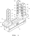
- FIG. 1 there is shown one embodiment of the gripper tooling mounted to an illustrative gripper with parallel jaw travel 50, such as the GRH series gripper manufactured by the PHD Corporation.
- Left tooling member 100 consists of a single gripper "finger" including a base 101 to which is attached a chain of multiple identical articulated segments 110, capped by an articulated distal segment 120.
- a slider 102 attaches left tooling member 100 to the left jaw 51 of gripper 50 with threaded fasteners (not shown, see also Fig. 11 ).
- Right tooling member 200 consists of a base 201 to which is attached two gripper fingers comprising multiple identical articulated segments 210, capped by identical articulated distal segments 220.
- a slider 202 attaches right tooling member 200 to the right jaw 52 of gripper 50 with threaded fasteners (not shown).
- the embodiment illustrates similar finger construction for the left and right fingers, it will be understood by one skilled in the art that the articulated segments comprising the left and right fingers can also differ in quantity, overall dimensions, construction, and physical arrangement from those illustrated. It is also understood that left and right fingers need not be of similar construction to one another and that the quantity of fingers present on each tooling member can be varied without affecting the fundamental nature of the invention.
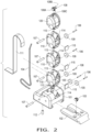
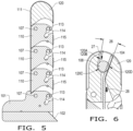
- Figs. 2-6 there is shown the left tooling member 100.
- Ribs protruding from the sides of slider 102 are disposed into complementary slots in the base 101 so as to prevent the rotation of the base 101 with respect to the slider and limit the translation of the base 101 in all directions except along the longitudinal axis of slider 102.
- a bevel on the forward edge of slider 102 acts to lift any portion of the workpiece that the slider may contact out of the path of the slider as the slider, mechanically fastened to the left jaw 51 of gripper 50, moves towards the workpiece.
- the left tooling member 100 may include an adducting tendon 104 having a proximal end connected to the slider 102 and a distal end connected to the distal segment 120.
- the adducting tendon 104 may be in the form of a cable 104.
- a lower knurled cylindrical cleat 103 may mechanically fasten the proximal end of the cable 104 to the slider 102.
- the cable 104 may be attached with a suitable adhesive applied between the cable 104 and the slider 102.
- the cable 104 may be composed of any desired material.
- the cable 104 is a polymer cable which offers the advantages over traditional steel cable of improved resistance to fatigue and corrosion, greater flexibility, improved dissipation of mechanical shock, and lower cost.
- a set of pulleys 105 supported by pivot pins 106 pressed into complimentary holes in body 101, route the motion of cable 104 so that as the proximal end of the cable 104 is pulled by the motion of slider 102 relative to body 101, cable 104 is drawn through the central passages of articulated segments 110.
- pulleys 105 are shown as being directly supported by pivot pins 106, it is understood that a suitable commercial bearing bushing, radial ball bearing, or needle bearing could be interposed between the pulley and pin when the size of pulley 105 is sufficiently large to allow doing so.
- Pivot pins 107 pass though complimentary holes in base 101 and segments 110 and 120 to attach common segments 110 to base 101, to each other, and to distal segment 120, forming a chain of pinned articulated segments radiating outwards from base 101.
- segments 110 and segment 120 are shown as being directly supported by pivot pins 107, it is understood that a suitable commercial bearing bushing, radial ball bearing, or needle bearing could be interposed between the pivot hole in the segments and pin 107 when the size of segment is sufficiently large to allow doing so.
- the upper, distal end of the cable 104 may be mechanically fastened to the distal segment 120 with an upper knurled cylindrical cleat 108. It is understood that such mechanical attachment could also be affected with a suitable adhesive applied between the cable 104 and the segment 120. Cable 104 passes over pulleys 109 disposed within each identical segment 110. In this manner, cable 104, suitably attached between slider 102 and distal segment 120, effectively forms the taut adducting tendon 104 located on one side of segment pivot pins 107.
- pulleys 109 are shown as being directly supported by pivot pins 106 pressed into complimentary holes in segments 110, it is understood that a suitable commercial bearing bushing, radial ball bearing, or needle bearing could be interposed between the pulley and pin when the size of pulley 109 is sufficiently large to allow doing so.
- the left tooling member 100 may include an abducting tendon 111.
- An external strip 111 may effectively form the abducting tendon 111, which is located on the opposing side of pivot pins 107.
- the external strip 111 may be composed of a suitable elastomeric material.
- the distal end of the strip 111 is attached in any desired way, such as thermal or adhesive bonding, into a complimentary groove in distal segment 120.
- the proximal end of elastomeric strip 111 is disposed within a complementary slot in body 101 and is attached to body 101 by the clamping action of set-screw 112 or by other suitable thermal or adhesive bonding.
- the portion of strip 111 between the distal and proximal attached ends is unconstrained and free to stretch or relax.
- strip 111 is stretched during installation to create a tension in the strip 111 which acts to pull distal segment 120 toward base 101. This pull induces a torque in distal segment 120 and common segments 110 which acts to rotate each segment counterclockwise (CCW) with respect to pivot pins 107.
- strip 111 could be replaced by one or more helical extension springs or a flexible, but non-stretchable tensile member attached to a suitable spring to provide the same function as an elastomeric strip.
- Bosses 113 protruding from the sides of common segments 110, engage complimentary slots 114, in body 101 and segments 110 to constrain the angle of CCW rotation of the segment pinned to base 101 and each successive pinned segment in the segment chain, relative to the prior segment.
- bosses 113 protruding from the sides of common segments 110, engage complimentary slots 114, in body 101 and segments 110 to constrain the angle of CCW rotation of the segment pinned to base 101 and each successive pinned segment in the segment chain, relative to the prior segment.
- Clockwise (CW) rotation of any segment under the influence of an external torque causes additional stretching of strip 111, with a resulting increase in the torque applied by the strip to the CW rotated segment.
- strip 111 functions as an abducting tendon which constantly applies a torque to segments 110 and 120 about pivot pin 107 to restore the segments into straight vertical alignment with one another.
- Downward motion of adductor cable 104 through the central passages of segments 110 induces a CW torque in segments 110 and 120 that causes the segments to rotate CW about pivot pins 107, further stretching abductor strip 111.
- Pads 115 are suitably bonded into complimentary recesses in segments 110.
- Pads 115 are constructed of a material such as a suitable elastomer or a nanodiamond impregnated metal substrate, possessing a high coefficient of static friction, so as to enhance the frictional forces generated between the pad and any surface of the gripped workpiece that the pad might contact.
- Dimension 20 indicates the orthogonal distance between the center of pivot pin 107 connecting the proximal most common segment 110 to base 101 and the centerline of adductor cable 104.
- Dimension 21 indicates the orthogonal distance between the respective pivot pins 107 of the remaining segments and the centerline of cable 104.
- Dimension 22 indicates the orthogonal distance between the pivot pins 107 of the remaining segments and the centerline of abductor strip 111.
- the CW acting torque about pivot pins 107 applied to the various segments by the tension in adductor cable 104 is equal to the product of the tension in the cable and the orthogonal distance between the respective pivot pin and the centerline of the adductor cable 104.
- the CCW acting torque about pivot pins 107 applied to the various segments by the tension in abductor strip 111 is equal to the product of the tension in the strip and the orthogonal distance between the respective pivot pin and the centerline of the abductor strip. It will be evident to one skilled in the art that as the tension in cable 104 when pulled upon is constant along the entire length of the cable, only the orthogonal distance between the center of the respective pivot pin 107 and cable centerline needs be varied to control the torque applied by cable 104 to any given segment.
- the local tension in abductor strip 111 is a function of the cross-sectional area of the strip at that locality, so that the local tension in the strip can be controlled by selectively varying the cross-sectional area of strip 111 along the length of the strip. Therefore, the net torque acting on any given segment can be chosen by controlling the local cross-sectional area of strip 111, the distance between the respective pivot pin 107 of the segment and the centerline of abductor strip 111, and the distance between the respective pivot pin 107 of the segment and the centerline of adductor cable 104. It will also be evident that in the absence of any external torques acting upon the segments, the segment with the greatest net applied CW torque will rotate toward the workpiece first, with each remaining segment successively rotating in descending order of net applied CW torque.
- Cleat 108 mechanically fastens the distal end of adductor cable 104 to distal segment 120.
- Cleat 108 is comprised of central cylinder 108C the outer diameter of which receives a straight knurl or other friction enhancing treatment such as a nanodiamond impregnated plating.
- Bosses 108A and 108B flank central cylinder 108C ( Fig. 2 ).
- a complimentary relief 120C forms a cleat cavity 120C within segment 120 to prevent any portion of the central cylinder 108C of cleat 108 from contacting any portion of segment 120 ( Figs. 2 and 6 ).
- Central cylinder 108C is free to contact the surface of cable 104 which is pressed into contact with surface 120D of segment 120 by the action of central cylinder 108C.
- Angle 26 denotes the angle formed by surfaces 120A and 120B and cable contact surface 120D in segment 120. Angle 26 is chosen to be shallow, in the range of 10 to 30 degrees.
- Arrow 27 indicates the force applied to cleat central cylinder 108A to install cleat 108 into cleat cavity 120C of distal segment 120. While cable 104 is held taut, Force 27 is applied to the left of the axis of central cylinder 108C as cleat 108 is guided into the mouth of recess 120C, causing the surface of cylinder 108C to roll CCW against the surface of cable 104 while surfaces 108A and 108B slide against surfaces 120A and 120B, respectively.
- the acute nature of angle 26 creates a wedging action which decreases the space between surfaces 120A and 120B and 120D as cleat 108 moves progressively into recess 120C.
- Figs. 7-10 there is shown the right tooling member 200.
- Ribs protruding from the sides of slider 202 are disposed into complementary slots in base 201 so as to prevent the rotation of the base 201 with respect to the slider and limit the translation of base 201 in all directions except along the longitudinal axis of slider 202.
- a bevel on the forward edge of slider 202 acts to lift any portion of the workpiece that the slider may contact out of the path of the slider as the slider, mechanically fastened to the right jaw 52 of gripper 50, moves towards the workpiece.
- Pivot pins 207 pass though complimentary holes in base 201 and segments 210 and 220 to attach common segments 210 to base 201, to each other, and to distal segment 220, forming two chains of pinned articulated segments radiating outwards from base 201.
- segments 210 and segment 220 are shown as being directly supported by pivot pins 207, it is understood that a suitable commercial bearing bushing, radial ball bearing, or needle bearing could be interposed between the pivot hole in the segments and pin 207 when the size of segment is sufficiently large to allow doing so.
- the right tooling member 200 may include an adducting tendon 204 having a proximal center portion connected to the slider 202 and distal ends connected to the distal segments 220.
- the adducting tendon 204 may be in the form of a cable 204.
- the proximal center portion of cable 204 is routed around pulleys 216 which are supported by pivot pins 206 pressed into complimentary holes in slider 202.
- cable 204 is a polymer cable which offers the advantages over traditional steel cable of improved resistance to fatigue and corrosion, greater flexibility, improved dissipation of mechanical shock, and lower cost.
- Pulleys 205 supported by pivot pins 206 pressed into complimentary holes in body 210, route the motion of each end of cable 204 so that as the proximal center of the cable 204 is pulled by the motion of slider 202 relative to body 201, each end of cable 204 is drawn through the central passages of articulated segments 210 of one of the two segment chains.
- pulleys 205 are shown as being directly supported by pivot pins 206, it is understood that a suitable commercial bearing bushing, radial ball bearing, or needle bearing could be interposed between the pulley and pin when the size of pulley 205 is sufficiently large to allow doing so.
- Each distal end of cable 204 can be mechanically fastened to distal segment 220 of one segment chain with knurled cylindrical cleat 208. It is understood that such mechanical attachment could also be affected with a suitable adhesive applied between the cable 204 and the segment 220. It is further understood that the same wedging mechanism used by cleat 108 to retain the distal end of cable 104 within distal segment 120 is also used to by cleats 208 to retain each distal end of cable 204 in distal segments 220.
- Cable 204 passes over pulleys 209 disposed within each identical segment 210.
- each side of cable 204 suitably attached between slider 202 and distal segment 220, effectively forms a taut adducting tendon located on one side of segment pivot pins 207.
- pulleys 209 are shown as being directly supported by pivot pins 206 pressed into complimentary holes in segments 210, it is understood that a suitable commercial bearing bushing, radial ball bearing, or needle bearing could be interposed between the pulley and pin when the size of pulley 209 is sufficiently large to allow doing so.
- each of the two segment chains of tooling member 200 may contact and conform to the profile of a gripped workpiece independently of one another. Such independent conformance assists during the gripping of workpieces possessing a plurality of asymmetric profiles by maximizing the number of contact points between the tooling and workpiece.
- the articulated motion of any segment chain ceases when that chain fully conforms to the profile of the gripped workpiece, causing motion of the end of cable 204 attached to the fully conformed segment chain to correspondingly cease and become stationary.
- the strip 211 constructed of a suitable elastomeric material, effectively forms an abducting tendon located on the opposing side of pivot pins 207.
- the distal end of strip 211 is attached by suitable means, such as thermal or adhesive bonding, into a complimentary groove in distal segment 220.
- the proximal end of elastomeric strip 211 is disposed within a complementary slot in body 201 and is attached to body 201 by the clamping action of set-screw 212 or by other suitable thermal or adhesive bonding.
- the portion of strip 211 between the distal and proximal attached ends is unconstrained and free to stretch or relax.
- the strip 211 is stretched during installation to create a tension in the strip which acts to pull distal segment 220 toward base 201.
- This pull induces a torque in distal segment 220 and common segments 210 which acts to rotate each segment CW with respect to pivot pins 207 ( Fig. 9 ).
- the strip 211 could be replaced by one or more helical extension springs or a flexible, but non-stretchable tensile member attached to a suitable spring to provide the same function as an elastomeric strip. It should be appreciated that the orientation of member 200 is reversed in Fig. 7 when compared to Fig. 9 .
- bosses 213 within slots 214 the segments cannot rotate CW about pivots 207 beyond a position in which the segments are in a straight, vertical alignment with one another.
- strip 211 functions as an abducting tendon which constantly applies a torque to segments 210 and 220 about pivot pin 207 to restore the segments into straight vertical alignment with one another.
- Downward motion of adductor cable 204 through the central passages of segments 210 induces a CCW torque in segments 210 and 220 that causes the segments to rotate CCW about pivot pins 207, further stretching abductor strip 211.
- Pads 215 are suitably bonded into complimentary recesses in segments 210.
- Pads 215 are constructed of a material such as a suitable elastomer or a nanodiamond impregnated metal substrate, possessing a high coefficient of static friction, so as to enhance the frictional forces generated between the pad and any surface of the gripped workpiece that the pad might contact.
- Dimension 23 indicates the orthogonal distance between the center of pivot pin 107 connecting the proximal most common segment 210 to base 201 and the centerline of adductor cable 204.
- Dimension 24 indicates the orthogonal distance between the respective pivot pins 207 of the remaining segments and the centerline of cable 204.
- Dimension 25 indicates the orthogonal distance between the pivot pins 207 of the remaining and the centerline of abductor strip 211.
- the cross-sectional area of corresponding abductor strip 211 and orthogonal distances between the pivot pins 207 and centerlines of strip 211 and abductor cable 204 can be similarly chosen to control the rotational order of each segment chain.
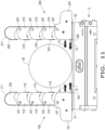
- Figs. 11-13 there is shown the gripper tooling in its sequence operation as the gripper tooling engages an example of a workpiece 30.
- the left jaw 51 and right jaw 52 move the left tooling member 100 and the right tooling member 200 toward cylindrical workpiece 30, in the direction of arrows 12 and 13, respectively.
- the segments comprising the left tooling member 100 and the right tooling member 200 are held in straight vertical alignment by the tension of the stretched elastomeric strips 111 and 211, respectively.
- cables 104 and 204 remain taut, which prevents any relative motion between sliders 102 and base 101 and slider 202 and base 201, as any relative motion between the sliders and bases require CW rotation of segments about pivot pins 107 or CCW rotation of the segments about pivot pins 207 (see also Figs. 4 and 9 ).
- the bases 101 and 201 therefore move in conjunction with respective sliders 102 and 202, as denoted by arrows 14 and 15, respectively.
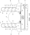
- Fig. 12 shows tooling members 100 and 200 at the moment of initial contact with the workpiece 30.
- the finger formed by segments 110 and distal segment 120 pinned together by pivot pins 107 is brought to rest.
- Base 101 is also brought to rest by the action of segment 110 acting through the pinned connection to base 101 established by pivot pin 107.
- slider 102 remains free to translate under the influence of jaw 51, to which it is fastened, as denoted by arrow 12.
- the finger formed by segments 210, distal segments 220, and pivot pins 207 is brought to rest by contact with workpiece 30.
- Base 201 is brought to rest by the action of segment 210 acting through the pinned connection to base 201 established by pivot pin 207, while slider 202 remains free to translate under the influence of jaw 52, as denoted by arrow 13.
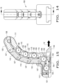
- Figs. 11-17 there is shown the tooling members 100 and 200 gripping the workpiece 30.
- slider 102 Once base 101 is brought to rest by the segment chain, including segments 110 and 120 and pins 107, acting against workpiece 30, slider 102 continues to translate under the action of gripper jaw 51, relative to stationary base 101.
- Such relative motion pulls adductor cable 104, routed around pulleys 105, downward through the central passages of segments 110.
- Figs. 15 and 17 there is shown the tooling members 100, 200 in the actuated, encapsulating position.
- the small black arrows denote both the direction of motion and the direction of the corresponding motive tension of adductor cables 104, 204 as the cables 104, 204 are drawn through the respective central passages of segments 110, 210.
- the cross-sectional area of strip 111 is kept constant along the length of the strip and orthogonal distance 22 is kept constant for all segments while the value of orthogonal distance 20 for the proximal most segment 110 pinned to base 101 is chosen to be greater than the value of distance 21 for the remainder of the segments.
- the cross-sectional area of strip 211 is chosen to match that of strip 111 and the values for the orthogonal distances 23, 24, and 25 are chosen to match the values chosen for distances 20, 21, and 22, respectively.
- This form increases the force applied to the gripped workpiece by the proximal most segments 110 and 210 while reducing the forces applied to the workpiece by the remaining segments.
- Concentrating the force distribution toward the proximal end of the segment chains provides the advantage of reducing the moments generated about sliders 102 and 202, by the finger chains during gripping, reducing the reaction forces between the bases and sliders and the frictional losses that arise from these reaction forces which reduce the efficiency of the gripper.
- the cross-sectional area of strips 111 and 211 is progressively reduced from the proximal end to the distal end of each strip and orthogonal distances 22 and 25 are kept equal for all segments.
- the values of orthogonal distances 20 and 23 for the proximal most segments are made equal to values for distances 21 and 24 for the remainder of the segments.
- This form causes the distal segments 120 and 220 to rotate first when the segment chain contacts the workpiece, with the remainder of the respective segment chains rotating in succession from the distal most to the proximal most segments.
- This manner of progressive distal to proximal rotation provides the advantage of pushing the contacted workpiece progressively toward the gripper, so that the gripped workpiece rests as closely as possible to the gripper.
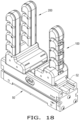
- FIG. 18 there is shown another embodiment of a gripper tooling in which the tooling members 100 and 200 upon gripper 50 are juxtaposed.
- This form provides for gripping during the opening, rather than the closing, of the gripper jaws 51 (not shown) and 52.
- Such a manner of gripping is desirable when the workpiece is hollow such as a pipe, hoop or torus and needs to be gripped from the interior opening.
- a magnet is added to sliders 102 and 202 and a magnet sensing switch is added to bases 101 and 201, allowing each switch to detect the position of the respective slider relative to the respective base. Detecting relative motion between each respective slider and base provides a desirable means of electronically communicating the onset of contact between each tooling member and the gripped workpiece. This allows the gripper jaws 51, 52 to move rapidly toward the workpiece, but then slow down to allow for a more precise gripping and/or for the gripping force to be limited until contact with a workpiece is detected and/or verified to be in a desired location in order to enhance operational concerns.
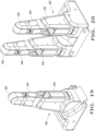
- FIG. 19-20 there is shown another embodiment of the present invention which includes left and right tooling members 300, 400.
- the segment chains are chosen to resemble the number, size, shape, and physical proportions of a representative human finger or thumb.
- Right tooling member 300 comprises a single segment chain while left tooling member 400 comprises two or more segment chains.
- the segment chain of tooling member 300 can be chosen to comprise a proximal 330, middle 340 and distal segment 350 to resemble a human finger or only a proximal 330 and distal 350 segment to resemble a human thumb.
- Each segment chain of tooling member 400 comprises a proximal 430, middle 440 and distal segment 450 to resemble a human finger.
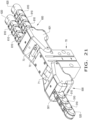
- FIG. 21-24 there is shown another embodiment of the present invention which is configured to mount to an illustrative gripper with angular jaw travel 70, such as the GRB series gripper manufactured by the PHD Corporation.
- Left tooling member 500 generally includes a single finger having a base 501 to which is attached a chain of multiple identical articulated segments 510, capped by articulated distal segment 520.
- Rotor 502 attaches left tooling member 500 to the left jaw 71 of gripper 70 with threaded fasteners 73 (not shown in Fig. 21 ).
- Right tooling member 600 generally includes a base 601 to which is attached two fingers having multiple identical articulated segments 610, capped by identical articulated distal segments 620.
- Rotor 602 attaches right tooling member 600 to the right jaw 72 of gripper 70 with threaded fasteners 73 (only one of two is shown in Fig. 21 ).
- the present embodiment illustrates similar finger construction for the left and right fingers, it should be appreciated by one skilled in the art that the articulated segments having the left and right fingers can also differ in quantity, overall dimensions, construction, and physical arrangement from those illustrated. It is also understood that left and right fingers need not be of similar construction to one another and that the quantity of fingers present on each tooling member can be varied without affecting the fundamental nature of the invention.
- Fig. 22 there is shown the left tooling member 500.
- the pins 517 pass through complimentary holes in base 501 and are pressed into complementary holes in rotor 502 so as to allow the rotation of the rotor 502 with respect to the base 501 while preventing the translation of base 501 with respect to rotor 502.
- Complimentary countersunk holes in rotor 502 allow the rotor to be mechanically fastened with threaded fasteners 73 (not shown in Fig.22 ) to the left jaw 71 of gripper 70.
- the left tooling member 500 may include an adducting tendon 504 having a proximal end connected to the rotor 502 and a distal end connected to the distal segment 520.
- the adducting tendon 504 may be in the form of a cable 504.
- the cylindrical cleat 518 mechanically fastens the proximal end of the cable 504 to rotor 502 by compressing the cable 504 against cleat plate 519, the vertical sides of which are disposed within complimentary slots within rotor 502.
- the cylindrical ends of cleat 518 are suitably retained within angled complimentary slots within rotor 502. In this manner, cable 502 is held frictionally captured by the action of cleat 518 against plate 519.
- the cable 504 is a polymer cable which offers the advantages over traditional steel cable of improved resistance to fatigue and corrosion, greater flexibility, improved dissipation of mechanical shock, and lower cost.
- pulleys 505 are shown as being directly supported by pivot pins 506, it is understood that a suitable commercial bearing bushing, radial ball bearing, or needle bearing could be interposed between the pulley and pin when the size of pulley 505 is sufficiently large to allow doing so.
- Pivot pins 507 pass though complimentary holes in base 501 and segments 510 and 520 to attach common segments 510 to base 501, to each other, and to distal segment 520, forming a chain of pinned articulated segments radiating outwards from base 501.
- segments 510 and segment 520 are shown as being directly supported by pivot pins 507, it should be appreciated that a suitable commercial bearing bushing, radial ball bearing, or needle bearing could be interposed between the pivot hole in the segments and pin 507 when the size of segment is sufficiently large to allow doing so.
- cable 504 is mechanically fastened to distal segment 520 with knurled cylindrical cleat 508. However, it should be appreciated that such mechanical attachment could also be affected with a suitable adhesive applied between the cable and the segment. Cable 504 passes over pulleys 509 disposed within each identical segment 510. In this manner, cable 504, suitably attached between rotor 502 and distal segment 520, effectively forms a taut adducting tendon located on one side of segment pivot pins 507.
- pulleys 509 are shown as being directly supported by pivot pins 506 pressed into complimentary holes in segments 510, it is understood that a suitable commercial bearing bushing, radial ball bearing, or needle bearing could be interposed between the pulley and pin when the size of pulley 509 is sufficiently large to allow doing so.
- the strip 511 constructed of a suitable elastomeric material, effectively forms an abducting tendon located on the opposing side of pivot pins 507.
- the distal end of strip 511 is attached by suitable means, such as thermal or adhesive bonding, into a complimentary groove in distal segment 520.
- the proximal end of elastomeric strip 511 is disposed within a complementary slot in body 501 and is attached to body 501 by the clamping action of set-screws 512 or by other suitable thermal or adhesive bonding.
- the portion of strip 511 between the distal and proximal attached ends is unconstrained and free to stretch or relax.
- Strip 511 is stretched during installation to create a tension in the strip which acts to pull distal segment 520 toward base 501.
- strip 511 could be replaced by one or more helical extension springs or a flexible, but non-stretchable tensile member attached to a suitable spring to provide the same function as an elastomeric strip.
- bosses 513 protruding from the sides of common segments 510, engage complimentary slots 514, in body 501 and segments 510 to constrain the angle of CCW rotation of the segment pinned to base 501 and each successive pinned segment in the segment chain, relative to the prior segment.
- bosses 513 within slots 514 the segments cannot rotate CCW about pivots 507 beyond a position in which the segments are in a straight, vertical alignment with one another.
- Clockwise (CW) rotation of any segment under the influence of an external torque causes additional stretching of strip 511, with a resulting increase in the torque applied by the strip to the CW rotated segment.
- strip 511 functions as an abducting tendon which constantly applies a torque to segments 510 and 520 about pivot pin 507 to restore the segments into straight vertical alignment with one another.
- Downward motion of adductor cable 504 through the central passages of segments 510 induces a CW torque in segments 510 and 520 that causes the segments to rotate CW about pivot pins 507, further stretching abductor strip 511.
- the pads 515 are suitably bonded into complimentary recesses in segments 510.
- Pad 522 is suitably bonded into a complimentary recess in base 501.
- the pads 515 and 522 are constructed of a material such as a suitable elastomer or a nanodiamond impregnated metal substrate, possessing a high coefficient of static friction, so as to enhance the frictional forces generated between the pad and any surface of the gripped workpiece that the pad might contact.
- the cleat 508 fastens the distal end of cable 504 onto segment 520. It should be appreciated that the same wedging action used by the cleat 108 to retain the distal end of cable 104 within distal segment 120 is also used by the cleat 518 to retain the proximal end of cable 504 in rotor 502.
- Fig. 23 there is shown the right tooling member 600.
- the pins 617 pass through complimentary holes in base 601 are pressed into complementary holes in rotor 602 so as to allow the rotation of the rotor with respect to the base while preventing the translation of base 601 with respect to rotor 602.
- Complimentary countersunk holes in rotor 602 allow the rotor to be mechanically fastened with threaded fasteners 73 (not shown in Fig. 23 ) to the right jaw 72 of gripper 70.
- Pivot pins 607 pass though complimentary holes in base 601 and segments 610 and 620 to attach common segments 610 to base 601, to each other, and to distal segment 620, forming two chains of pinned articulated segments radiating outwards from base 601.
- segments 610 and segment 620 are shown as being directly supported by pivot pins 607, it is understood that a suitable commercial bearing bushing, radial ball bearing, or needle bearing could be interposed between the pivot hole in the segments and pin 607 when the size of segment is sufficiently large to allow doing so.
- the right tooling member 600 may include an adducting tendon 604 having a proximal end connected to the rotor 602 and a distal end connected to the distal segment 620.
- the adducting tendon 604 may be in the form of a cable 604.
- the proximal center portion of cable 604 is routed around pulleys 616 which are supported by pivot pins 606 pressed into complimentary holes in rotor 602.
- the cable 604 is a polymer cable which offers the advantages over traditional steel cable of improved resistance to fatigue and corrosion, greater flexibility, improved dissipation of mechanical shock, and lower cost.
- pulleys 605 and 616 are shown as being directly supported by pivot pins 621 and 606 respectively, it is understood that a suitable commercial bearing bushing, radial ball bearing, or needle bearing could be interposed between the pulley and pin when the size of pulley 605 and/or 616 is sufficiently large to allow doing so.
- Each distal end of cable 604 can be mechanically fastened to distal segment 620 of one segment chain with knurled cylindrical cleat 608. It should be appreciated that such mechanical attachment could also be affected with a suitable adhesive applied between the cable and the segment. It should be further appreciated that the same wedging mechanism used by the cleat 508 to retain the distal end of cable 504 within distal segment 520 is also used to by the cleats 608 to retain each distal end of cable 604 in distal segments 620.
- Cable 604 passes over pulleys 609 disposed within each identical segment 610.
- pulleys 609 are shown as being directly supported by pivot pins 606 pressed into complimentary holes in segments 610, it is understood that a suitable commercial bearing bushing, radial ball bearing, or needle bearing could be interposed between the pulley and pin when the size of pulley 609 is sufficiently large to allow doing so.
- each of the two segment chains of tooling member 600 may contact and conform to the profile of a gripped workpiece independently of one another. Such independent conformance assists during the gripping of workpieces possessing a plurality of asymmetric profiles by maximizing the number of contact points between the tooling and workpiece.
- the articulated motion of any segment chain ceases when that chain fully conforms to the profile of the gripped workpiece, causing motion of the end of cable 604 attached to the fully conformed segment chain to correspondingly cease and become stationary.
- the ability of the cable 604 to laterally translate across pulleys 616 subsequently allows the length of the cable to shift from the free end to the stationary end, allowing the free end of cable 604 to continue to be pulled by the action of rotor 602 rotating relative to body 601. Once both segments chains have completely conformed to the workpiece, the ability of cable 604 to translate laterally across pulleys 616 further provides a way of equalizing the tension between the two ends of the cable 604.
- the strip 611 constructed of a suitable elastomeric material, effectively forms an abducting tendon located on the opposing side of pivot pins 607.
- the distal end of strip 611 is can be attached by any desired fastener or adhesive, such as thermal or adhesive bonding, into a complimentary groove in distal segment 620.
- the proximal end of elastomeric strip 611 is disposed within a complementary slot in body 601 and is attached to body 601 by the clamping action of set-screws 612 or by other suitable thermal or adhesive bonding.
- the portion of strip 611 between the distal and proximal attached ends is unconstrained and free to stretch or relax.
- Strip 611 is stretched during installation to create a tension in the strip which acts to pull distal segment 620 toward base 601.
- strip 611 could be replaced by one or more helical extension springs or a flexible, but non-stretchable tensile member attached to a suitable spring to provide the same function as an elastomeric strip.
- bosses 613 protruding from the sides of common segments 610, engage complimentary slots 614, in body 601 and segments 610 to constrain the angle of CW rotation of the segment pinned to base 601 and each successive pinned segment in the segment chain, relative to the prior segment.
- bosses 613 within slots 614 the segments cannot rotate CW about pivots 607 beyond a position in which the segments are in a straight, vertical alignment with one another.
- the pads 615 are suitably bonded into complimentary recesses in segments 610.
- the pad 622 is suitably bonded into a complimentary recess in base 601.
- the pads 615 and 622 are constructed of a material such as a suitable elastomer or a nanodiamond impregnated metal substrate, possessing a high coefficient of static friction, so as to enhance the frictional forces generated between the pad and any surface of the gripped workpiece that the pad might contact.
- Fig. 24 there is shown the tooling members 500 and 600 gripping the example of the cylindrical workpiece 30.
- rotor 502 continues to rotate in the direction of arrow 29L under the action of gripper jaw 71, relative to stationary base 501.
- Such relative motion pulls adductor cable 504, routed around pulleys 505, downward through the central passages of segments 510.
Landscapes
- Engineering & Computer Science (AREA)
- Robotics (AREA)
- Mechanical Engineering (AREA)
- Manipulator (AREA)
- Gripping Jigs, Holding Jigs, And Positioning Jigs (AREA)
Claims (15)
- Greifwerkzeug, umfassend:einen Greifer (50) mit einem Greiferkörper und zumindest einer Klaue (51, 52), die mit dem Greiferkörper verbunden und relativ zu diesem linear gleitbeweglich ist;zumindest einen Schieber (102, 202), der mit der zumindest einen Klaue (51, 52) verbunden ist; undzumindest ein Werkzeugelement (100, 200, 300, 400) zum Ergreifen eines Werkstücks (30), wobei das Werkzeugelement (100, 200, 300, 400) jeweils umfasst:eine Basis (101, 201), die gleitbeweglich an dem zumindest einen Schieber (102, 202) gelagert ist;zumindest ein mittleres Segment (110, 210, 340, 440), das schwenkbar mit der Basis (101, 201) verbunden ist;ein distales Segment (120, 220, 350, 450), das schwenkbar mit dem zumindest einen mittleren Segment (110, 210, 340, 440) verbunden ist;eine Adduktionssehne (104, 204) mit einem proximalen Ende, das an den zumindest einen Schieber (102, 202) befestigt ist, und einem distalen Ende, das an das distale Segment (120, 220, 350, 450) befestigt ist; undeine Abduktionssehne (111, 211) mit einem proximalen Ende, das an die Basis (101, 201) befestigt ist, und einem distalen Ende, das an das distale Segment (120, 220, 350, 450) befestigt ist, so dass das zumindest eine Werkzeugelement (100, 200, 300, 400) dazu ausgelegt ist, das Werkstück (30) selbsttätig zu ergreifen, wenn die zumindest eine Klaue (51, 52) sich auf das Werkstück zu bewegt, und das zumindest eine Werkzeugelement (100, 200, 300, 400) dazu ausgelegt ist, selbsttätig in eine Freigabeposition zurückzukehren, wenn die zumindest eine Klaue (51, 52) sich von dem Werkstück (30) weg bewegt,wobei das zumindest eine Werkzeugelement (100, 200, 300, 400) dazu ausgelegt ist, das Werkstück (30) zu ergreifen, sobald die Basis (101, 201) über das zumindest eine gegen das Werkstück (30) wirkende Werkzeugelement (100, 200, 300, 400) in Ruhestellung gebracht ist, wobei der Schieber (102, 202) dazu ausgelegt ist, sich daraufhin unter der Wirkung der Greiferklaue (51, 52) relativ zur ortsfesten Basis (101, 201) weiter zu verschieben, wodurch die Abduktionssehne (111, 211) gestreckt wird,wobei als Abduktionssehne (111, 211) ein äußerer Strang fungiert, der aus einem Elastomermaterial oder einer Feder besteht und dazu ausgelegt ist, stetig ein Drehmoment auf die Segmente (110, 120, 210, 220) aufzubringen, um die Segmente zurückzustellen.
- Greifwerkzeug nach Anspruch 1, wobei die Basis (101, 201) dazu ausgelegt ist, beim Ergreifen des Werkstücks durch das Werkstück festgelegt zu werden, und wobei der zumindest eine Schieber (102, 202) dazu ausgelegt ist, relativ zur Basis (101, 201) in Richtung des Werkstücks zu gleiten, wodurch die Adduktionssehne (104, 204) gespannt und eine Drehung des zumindest einen mittleren Segments (110, 210, 340, 440) und des distalen Segments (120, 220, 350, 450) in einer ersten Richtung hervorgerufen wird, um das Werkstück zu ergreifen, und
wobei vorzugsweise beim Ergreifen des Werkstücks die Abduktionssehne (111, 211) gestreckt wird, wenn sich das zumindest eine mittlere Segment (110, 210, 340, 440) und das distale Segment (120, 220, 350, 450) in der ersten Richtung drehen, und wobei in der Freigabeposition die Abduktionssehne (111, 211) dazu ausgelegt ist, das zumindest eine mittlere Segment (110, 210, 340, 440) und das distale Segment (120, 220, 350, 450) in einer zweiten Richtung zu drehen. - Greifwerkzeug nach Anspruch 1, ferner umfassend eine Vielzahl von Riemenscheiben, die im Inneren der Basis (101, 201) und des zumindest einen mittleren Segments (110, 210, 340, 440) angeordnet sind, wobei jede dieser Riemenscheiben dazu ausgelegt ist, mit der Adduktionssehne (104, 204) in Kontakt zu stehen.
- Greifwerkzeug nach Anspruch 1, wobei die Adduktionssehne (104, 204) im Inneren der Basis (101, 201), des zumindest einen mittleren Segments (110, 210, 340, 440) und des distalen Segments (120, 220, 350, 450) angeordnet ist.
- Greifwerkzeug nach Anspruch 1, wobei die zumindest eine Klaue (51, 52) eine erste Klaue (51) und eine zweite Klaue (52) umfasst, der zumindest eine Schieber (102, 202) einen ersten Schieber (102) und einen zweiten Schieber (102) umfasst und das zumindest eine Werkzeugelement (100, 200, 300, 400) ein erstes Werkzeugelement (100, 300) und ein zweites Werkzeugelement (200, 400) umfasst.
- Greifwerkzeug nach Anspruch 5, wobei das erste Werkzeugelement (100, 300) die Form eines ersten Fingers hat und das zweite Werkzeugelement (200, 400) die Form eines Paares von zweiten Fingern hat, die eine gemeinsame Basis (101, 201) haben, und wobei der zweite Finger jeweils zumindest ein mittleres Segment (210, 440), ein distales Segment (220, 450), eine Abduktionssehne (211) und eine Adduktionssehne (204) aufweist.
- Greifwerkzeug, umfassend:einen Greifer (70) mit einem Greiferkörper und zumindest einer abgewinkelten Klaue (71, 72);zumindest einen Rotor (502, 602), der drehbar mit der zumindest einen abgewinkelten Klaue (71, 72) verbunden ist; undzumindest ein Werkzeugelement (500, 600) zum Ergreifen eines Werkstücks (30), wobei das Werkzeugelement (500, 600) jeweils umfasst:eine Basis (501, 601), die schwenkbar mit dem zumindest einen Rotor (502, 602) verbunden ist;zumindest ein mittleres Segment (510, 610), das schwenkbar mit der Basis (501, 601) verbunden ist;ein distales Segment (520, 620), das schwenkbar mit dem zumindest einen mittleren Segment (510, 610) verbunden ist;eine Adduktionssehne (504, 604) mit einem proximalen Ende, das an den zumindest einen Rotor (502, 602) befestigt ist, und einem distalen Ende, das an das distale Segment (520, 620) befestigt ist; undeine Abduktionssehne (511, 611) mit einem proximalen Ende, das an die Basis (501, 601) befestigt ist, und einem distalen Ende, das an das distale Segment (520, 620) befestigt ist, so dass das zumindest eine Werkzeugelement (500, 600) dazu ausgelegt ist, das Werkstück (30) selbsttätig zu ergreifen, wenn sich die zumindest eine abgewinkelte Klaue (71, 72) in Richtung des Werkstücks (30) dreht, und das zumindest eine Werkzeugelement (500, 600) dazu ausgelegt ist, selbsttätig in eine Freigabeposition zurückzukehren, wenn sich die zumindest eine abgewinkelte Klaue (71, 72) von dem Werkstück (30) wegdreht,wobei das zumindest eine Werkzeugelement (500, 600) dazu ausgelegt ist, das Werkstück (30) zu ergreifen, sobald die Basis (501, 601) durch den Kontakt des zumindest einen Werkzeugelements (500, 600) mit dem Werkstück (30) in Ruhestellung gebracht ist, wobei der Rotor (502, 602) dazu ausgelegt ist, sich daraufhin unter der Wirkung der Greiferklaue (71, 72) relativ zur ortsfesten Basis (501, 601) weiterzudrehen, wodurch die Abduktionssehne (511, 611) gestreckt wird,wobei die Abduktionssehne (511, 611) aus einem aus einem Elastomermaterial oder einer Feder bestehenden Strang gebildet ist, der dazu ausgelegt ist, stetig ein Drehmoment auf die Segmente (510, 520, 610, 620) aufzubringen, um die Segmente zurückzustellen.
- Greifwerkzeug nach Anspruch 7, wobei die Basis (501, 601) dazu ausgelegt ist, beim Ergreifen des Werkstücks durch das Werkstück festgelegt zu werden, und der zumindest eine Rotor (502, 602) dazu ausgelegt ist, sich relativ zur Basis (501, 601) in Richtung des Werkstücks zu drehen, wodurch die Adduktionssehne (504, 604) gespannt und eine Drehung des zumindest einen mittleren Segments (510, 610) und des distalen Segments (520, 620) in einer ersten Richtung hervorgerufen wird, um das Werkstück zu ergreifen.
- Greifwerkzeug nach Anspruch 8, wobei beim Ergreifen des Werkstücks die Abduktionssehne (511, 611) gestreckt wird, wenn sich das zumindest eine mittlere Segment (510, 610) und das distale Segment (520, 620) in der ersten Richtung drehen, und in der Freigabeposition die Abduktionssehne (511, 611) dazu ausgelegt ist, das zumindest eine mittlere Segment (510, 610) und das distale Segment (520, 620) in einer zweiten Richtung zu drehen.
- Greifwerkzeug nach Anspruch 7, ferner umfassend eine Vielzahl von Riemenscheiben, die im Inneren der Basis (501, 601) und des zumindest einen mittleren Segments (510, 610) angeordnet sind, wobei jede dieser Riemenscheiben dazu ausgelegt ist, mit der Adduktionssehne (504, 604) in Kontakt zu stehen, und/oder
wobei die Adduktionssehne (504, 604) im Inneren der Basis (501, 601), des zumindest einen mittleren Segments (510, 610) und des distalen Segments (520, 620) angeordnet ist. - Greifwerkzeug nach Anspruch 7, wobei die zumindest eine abgewinkelte Klaue (71, 72) eine erste abgewinkelte Klaue (71) und eine zweite abgewinkelte Klaue (72) umfasst, wobei der zumindest eine Rotor (502, 602) einen ersten Rotor (502) und einen zweiten Rotor (602) umfasst und wobei das zumindest eine Werkzeugelement (500, 600) ein erstes Werkzeugelement (500) und ein zweites Werkzeugelement (600) umfasst, und
wobei vorzugsweise das erste Werkzeugelement (500) die Form eines ersten Fingers hat und das zweite Werkzeugelement (600) die Form eines Paares von zweiten Fingern hat, die eine gemeinsame Basis (601) haben, und wobei der zweite Finger jeweils zumindest ein mittleres Segment (610), ein distales Segment (620), eine Abduktionssehne (511, 611) und eine Adduktionssehne (504, 604) aufweist. - Verfahren zum Ergreifen eines Werkstücks (30), umfassend die folgenden Schritte:Bereitstellen eines Greifwerkzeugs, umfassend einen Greifer (50), der einen Greiferkörper und zumindest eine mit dem Greiferkörper beweglich verbundene Klaue (51, 52) aufweist, zumindest eine Lagerung (102, 202, 502, 602) in Form zumindest eines Schiebers (102, 202) oder zumindest eines Rotors (502, 602), der mit der zumindest einen Klaue (51, 52) verbunden ist, und zumindest ein Werkzeugelement (100, 200, 300, 400, 500, 600), das zum Ergreifen des Werkstücks ausgelegt ist, wobei jedes Werkzeugelement (100, 200, 300, 400, 500, 600) eine Basis (101, 201, 501, 601), die beweglich an der zumindest einen Lagerung (102, 202, 502, 602) gelagert ist, zumindest ein mittleres Segment (110, 210, 340, 440, 510, 610), das schwenkbar mit der Basis (101, 201, 501, 601) verbunden ist, ein distales Segment (120, 220, 350, 450, 520, 620), das schwenkbar mit dem zumindest einen mittleren Segment (110, 210, 340, 440, 510, 610) verbunden ist, eine Adduktionssehne (104, 204, 504, 604) mit einem proximalen Ende, das an die zumindest eine Lagerung (102, 202, 502, 602) befestigt ist, und mit einem distalen Ende, das an das distale Segment (120, 220, 350, 450, 520, 620) befestigt ist, und eine Abduktionssehne (111, 211, 511, 611) mit einem proximalen Ende, das an die Basis (101, 201, 501, 601) befestigt ist, und einem distalen Ende, das an das distale Segment (120, 220, 350, 450, 520, 620) befestigt ist, umfasst;Ergreifen des Werkstücks durch die zumindest eine Klaue (51, 52) unter mittels der Adduktionssehne (104, 204, 504, 604) erfolgender Bewegung der Basis (101, 201, 501, 601), um durch das Werkstück (30) festgelegt zu werden, wobei das zumindest eine Werkzeugelement (100, 200, 300, 400, 500, 600) dazu ausgelegt ist, das Werkstück (30) zu ergreifen, sobald die Basis (101, 201, 501, 601) über das zumindest eine gegen das Werkstück (30) wirkende Werkzeugelement (100, 200, 300, 400, 500, 600) oder durch Kontakt des zumindest einen Werkzeugelements (100, 200, 300, 400, 500, 600) mit dem Werkstück (30) in Ruhestellung gebracht ist, woraufhin sich der Schieber (102, 202) unter der Wirkung der Greiferklaue (51, 52, 71, 72) relativ zu der ortsfesten Basis (101, 201, 501, 601) weiter verschiebt oder der Rotor (502, 602) sich weiter dreht, wodurch die Abduktionssehne (111, 211, 511, 611) gestreckt wird; undFreigeben des Werkstücks (30) von der zumindest einen Klaue (51, 52) unter mittels der Abduktionssehne (111, 211, 511, 611) erfolgender Bewegung der Basis (101, 201, 501, 601) weg von dem Werkstück (30), wobei die Abduktionssehne (111, 211, 511, 611) aus einem aus einem Elastomermaterial oder einer Feder bestehenden Strang gebildet ist, der stetig ein Drehmoment auf Segmente (110, 120, 510, 610, 620) aufbringt, um die Segmente zurückzustellen.
- Verfahren nach Anspruch 12, wobei die zumindest eine Klaue (51, 52) relativ zum Greiferkörper linear gleitbeweglich ist und die Basis (101, 201) gleitbeweglich mit dem zumindest einen Schieber (102, 202) verbunden ist.
- Verfahren nach Anspruch 13, wobei die Basis (101, 201) dazu ausgelegt ist, in dem Schritt des Ergreifens des Werkstücks durch das Werkstück festgelegt zu werden, und der zumindest eine Schieber (102, 202) dazu ausgelegt ist, relativ zu der Basis (101, 201) in Richtung des Werkstücks zu gleiten, wodurch die Adduktionssehne (104, 204) gespannt und eine Drehung des zumindest einen mittleren Segments (110, 210, 340, 440) und des distalen Segments (120, 220, 350, 450) in einer ersten Richtung hervorgerufen wird, um das Werkstück zu ergreifen, und
wobei vorzugsweise in dem Schritt des Ergreifens des Werkstücks die Abduktionssehne (511, 611) gestreckt wird, wenn sich das zumindest eine mittlere Segment (510, 610) und das distale Segment (520, 620) in der ersten Richtung drehen, und in dem Schritt der Freigabe des Werkstücks die Abduktionssehne (511, 611) dazu ausgelegt ist, das zumindest eine mittlere Segment (510, 610) und das distale Segment (520, 620) in einer zweiten Richtung zu drehen. - Verfahren nach Anspruch 12, wobei die zumindest eine Klaue (51, 52, 71, 72) als zumindest eine relativ zum Greiferkörper drehbare abgewinkelte Klaue (71, 72) ausgebildet ist, der zumindest eine Rotor (502, 602) sich mit der abgewinkelten Klaue dreht, und die Basis (501, 601) schwenkbar mit dem zumindest einen Rotor (502, 602) verbunden ist, und
wobei vorzugsweise die Basis (501, 601) dazu ausgelegt ist, in dem Schritt des Ergreifens des Werkstücks durch das Werkstück festgelegt zu werden, und der zumindest eine Rotor (502, 602) dazu ausgelegt ist, sich relativ zu der Basis (501, 601) in Richtung des Werkstücks zu drehen, wodurch die Adduktionssehne (504, 604) gespannt und eine Drehung des zumindest einen mittleren Segments (510, 610) und des distalen Segments (520, 620) in einer ersten Richtung hervorgerufen wird, um das Werkstück zu ergreifen, und die Abduktionssehne (511, 611) gestreckt wird, wenn sich das zumindest eine mittlere Segment (510, 610) und das distale Segment (520, 620) in der ersten Richtung drehen, und in dem Schritt der Freigabe des Werkstücks die Abduktionssehne (511, 611) dazu ausgelegt ist, das zumindest eine mittlere Segment (510, 610) und das distale Segment (520, 620) in einer zweiten Richtung zu drehen.
Applications Claiming Priority (2)
| Application Number | Priority Date | Filing Date | Title |
|---|---|---|---|
| US201862682471P | 2018-06-08 | 2018-06-08 | |
| PCT/US2019/035390 WO2019236580A1 (en) | 2018-06-08 | 2019-06-04 | Autonomously encapsulating gripper tooling |
Publications (4)
| Publication Number | Publication Date |
|---|---|
| EP3802017A1 EP3802017A1 (de) | 2021-04-14 |
| EP3802017A4 EP3802017A4 (de) | 2022-03-16 |
| EP3802017C0 EP3802017C0 (de) | 2025-03-05 |
| EP3802017B1 true EP3802017B1 (de) | 2025-03-05 |
Family
ID=68765683
Family Applications (1)
| Application Number | Title | Priority Date | Filing Date |
|---|---|---|---|
| EP19814924.7A Active EP3802017B1 (de) | 2018-06-08 | 2019-06-04 | Autonom verkapselndes greifwerkzeug |
Country Status (8)
| Country | Link |
|---|---|
| US (2) | US11312022B2 (de) |
| EP (1) | EP3802017B1 (de) |
| JP (1) | JP7210615B2 (de) |
| KR (1) | KR102600256B1 (de) |
| CA (1) | CA3100219A1 (de) |
| ES (1) | ES3031511T3 (de) |
| MX (2) | MX2020012850A (de) |
| WO (1) | WO2019236580A1 (de) |
Families Citing this family (14)
| Publication number | Priority date | Publication date | Assignee | Title |
|---|---|---|---|---|
| JP6927852B2 (ja) * | 2017-11-01 | 2021-09-01 | Thk株式会社 | ハンド機構 |
| KR102600256B1 (ko) * | 2018-06-08 | 2023-11-08 | 피에이치디, 인크. | 자율적 캡슐화 그리퍼 툴링 |
| US11285617B2 (en) | 2019-12-31 | 2022-03-29 | Phd, Inc. | Modular articulating gripper |
| EP3900884B1 (de) * | 2020-04-20 | 2022-08-10 | C.R.F. Società Consortile per Azioni | Greifvorrichtung zum handhaben von gegenständen oder bauteilen unterschiedlicher form und grösse |
| JP6941790B1 (ja) * | 2020-05-26 | 2021-09-29 | 日本発條株式会社 | 関節装置 |
| DE102020114362A1 (de) * | 2020-05-28 | 2021-12-02 | Illinois Tool Works Inc. | System zum beladen einer spülmaschine, greifersystem für eine beladeanordnung zum beladen einer spülmaschine sowie spülmaschine |
| CN111791248B (zh) * | 2020-07-09 | 2021-11-26 | 北京理工大学 | 一种用于寒冷环境的柔性机械手 |
| CN113696213B (zh) * | 2021-09-18 | 2022-03-01 | 安徽理工大学 | 一种机械手 |
| DE102021133360A1 (de) | 2021-12-15 | 2023-06-15 | MATHEUS Industrie-Automation GmbH | Pneumatischer Greifarm mit Gelenken und Zugband |
| DE102021134454B3 (de) | 2021-12-23 | 2023-05-25 | Kuka Deutschland Gmbh | Greifer |
| KR102675972B1 (ko) * | 2022-08-31 | 2024-06-17 | 서울대학교산학협력단 | 비행체용 그리퍼 장치 |
| GB2622815B (en) * | 2022-09-28 | 2025-04-02 | Dyson Technology Ltd | Improvements in and relating to robotic grippers |
| KR102769579B1 (ko) * | 2022-11-18 | 2025-02-17 | 한양대학교 에리카산학협력단 | 표면 적응형 로봇 그리퍼 |
| KR102612581B1 (ko) * | 2023-06-16 | 2023-12-12 | (주)에이딘로보틱스 | 평행 운동이 가능한 적응형 그리퍼 |
Citations (1)
| Publication number | Priority date | Publication date | Assignee | Title |
|---|---|---|---|---|
| JP2010253571A (ja) * | 2009-04-21 | 2010-11-11 | Ihi Corp | 先端可動爪を有するチャックハンド |
Family Cites Families (27)
| Publication number | Priority date | Publication date | Assignee | Title |
|---|---|---|---|---|
| US2545452A (en) * | 1946-10-01 | 1951-03-20 | Maurice J Fletcher | Segmented articulated finger |
| US3694021A (en) | 1970-07-31 | 1972-09-26 | James F Mullen | Mechanical hand |
| US4185866A (en) | 1978-06-21 | 1980-01-29 | Cincinnati Milacron Inc. | External-internal gripper |
| US5092646A (en) * | 1989-06-20 | 1992-03-03 | Smallridge Bruce B | Double capstan winch drive |
| US5647723A (en) * | 1995-11-13 | 1997-07-15 | Rush; Joe A. | Memory wire robotic hand |
| US6874834B2 (en) | 1996-10-07 | 2005-04-05 | Phd, Inc. | Linear slide gripper |
| JP2001277174A (ja) | 2000-03-30 | 2001-10-09 | Miyazaki Prefecture | 指関節機構及びそれを用いた把持ユニット |
| US6505870B1 (en) | 2000-05-30 | 2003-01-14 | UNIVERSITé LAVAL | Actuation system for highly underactuated gripping mechanism |
| KR100451412B1 (ko) | 2001-11-09 | 2004-10-06 | 한국과학기술연구원 | 다지 로봇 핸드 |
| US20050121929A1 (en) * | 2002-03-25 | 2005-06-09 | Richard Greenhill | Humanoid robotics |
| JP2004223687A (ja) | 2003-01-27 | 2004-08-12 | Seiko Epson Corp | 多関節型マニピュレータ装置 |
| CN101518903B (zh) | 2009-03-27 | 2011-01-05 | 清华大学 | 曲柄滑块式欠驱动机器人手指装置 |
| KR101674894B1 (ko) | 2009-12-21 | 2016-11-10 | 삼성전자 주식회사 | 산업용 다자유도 그리퍼 |
| US8936289B1 (en) * | 2010-03-15 | 2015-01-20 | Telefactor Robotics LLC | Robotic finger assemblies |
| US8833826B2 (en) * | 2011-03-21 | 2014-09-16 | Sri International | Mobile robotic manipulator system |
| US8991884B2 (en) | 2011-03-21 | 2015-03-31 | Re2, Inc. | Robotic hand with conformal finger |
| CA2792645C (en) * | 2011-10-13 | 2017-01-17 | Phd, Inc. | Gripper with force-multiplying mechanism |
| CA2856622C (en) | 2011-11-25 | 2017-01-10 | Robotiq Inc. | A gripper having a two degree of freedom underactuated mechanical finger for encompassing and pinch grasping |
| US8757690B2 (en) | 2012-07-20 | 2014-06-24 | GM Global Technology Operations LLC | Reconfigurable gripping device |
| US8833827B2 (en) * | 2012-10-09 | 2014-09-16 | Willow Garage, Inc. | Kinetic and dimensional optimization for a tendon-driven gripper |
| JP5928303B2 (ja) * | 2012-11-07 | 2016-06-01 | 豊田合成株式会社 | 電動義手 |
| JP6479376B2 (ja) * | 2014-09-09 | 2019-03-06 | 満 入江 | 可動義手 |
| EP3191265A4 (de) | 2014-09-12 | 2018-05-16 | Polyvalor, Limited Partnership | Mechanischer finger für greifvorrichtung |
| EP3383599A4 (de) | 2015-12-03 | 2019-10-30 | SRI International Inc. | Robotergreifer |
| US9914214B1 (en) | 2016-02-22 | 2018-03-13 | X Development Llc | Preshaping for underactuated fingers |
| KR102600256B1 (ko) * | 2018-06-08 | 2023-11-08 | 피에이치디, 인크. | 자율적 캡슐화 그리퍼 툴링 |
| US11285617B2 (en) * | 2019-12-31 | 2022-03-29 | Phd, Inc. | Modular articulating gripper |
-
2019
- 2019-06-04 KR KR1020207034373A patent/KR102600256B1/ko active Active
- 2019-06-04 JP JP2020568275A patent/JP7210615B2/ja active Active
- 2019-06-04 WO PCT/US2019/035390 patent/WO2019236580A1/en not_active Ceased
- 2019-06-04 ES ES19814924T patent/ES3031511T3/es active Active
- 2019-06-04 EP EP19814924.7A patent/EP3802017B1/de active Active
- 2019-06-04 US US16/430,724 patent/US11312022B2/en active Active
- 2019-06-04 CA CA3100219A patent/CA3100219A1/en active Pending
- 2019-06-04 MX MX2020012850A patent/MX2020012850A/es unknown
-
2020
- 2020-11-27 MX MX2024009783A patent/MX2024009783A/es unknown
-
2022
- 2022-03-01 US US17/683,756 patent/US11685056B2/en active Active
Patent Citations (1)
| Publication number | Priority date | Publication date | Assignee | Title |
|---|---|---|---|---|
| JP2010253571A (ja) * | 2009-04-21 | 2010-11-11 | Ihi Corp | 先端可動爪を有するチャックハンド |
Also Published As
| Publication number | Publication date |
|---|---|
| US11685056B2 (en) | 2023-06-27 |
| EP3802017A1 (de) | 2021-04-14 |
| US20190375114A1 (en) | 2019-12-12 |
| JP2021526978A (ja) | 2021-10-11 |
| US20220234214A1 (en) | 2022-07-28 |
| EP3802017C0 (de) | 2025-03-05 |
| ES3031511T3 (en) | 2025-07-09 |
| US11312022B2 (en) | 2022-04-26 |
| KR102600256B1 (ko) | 2023-11-08 |
| JP7210615B2 (ja) | 2023-01-23 |
| CA3100219A1 (en) | 2019-12-12 |
| WO2019236580A1 (en) | 2019-12-12 |
| EP3802017A4 (de) | 2022-03-16 |
| KR20210008006A (ko) | 2021-01-20 |
| MX2024009783A (es) | 2024-08-19 |
| MX2020012850A (es) | 2021-02-17 |
Similar Documents
| Publication | Publication Date | Title |
|---|---|---|
| EP3802017B1 (de) | Autonom verkapselndes greifwerkzeug | |
| US5261263A (en) | Crimping pliers with radially opposed jaws | |
| CN108994864B (zh) | 双腱绳串联式耦合自适应手指装置 | |
| US10881903B2 (en) | Hand grip | |
| US11648688B2 (en) | Modular articulating gripper | |
| KR101932336B1 (ko) | 그리퍼 | |
| WO2016179793A1 (zh) | 弹性波纹管单作用气缸驱动串联板弹簧骨架机械手 | |
| US10263377B2 (en) | Crimping clamp | |
| US10913166B1 (en) | Gripper | |
| US8894118B2 (en) | Gripper with cable synchronized jaw movement | |
| TW559644B (en) | Belt installation tool | |
| US9796096B2 (en) | Gripper with indexable speed reducer | |
| US8677864B1 (en) | Compact cam actuated adjustable socket | |
| US9142931B2 (en) | Crimp tool with cam actuated crimp jaw | |
| CN111331587A (zh) | 腱绳驱动膨胀抓取滑杆自适应机器人手装置 | |
| GB2275831A (en) | Cable clamp | |
| US9724833B1 (en) | Shape-adaptive mechanism for robotic grasping | |
| EP4620628A1 (de) | Doppeltwirkender modularer gelenkiger greifer | |
| CN120269599B (zh) | 一种触发式快速抓握欠驱动手指机构 | |
| FR3128654A1 (fr) | Préhenseur | |
| HK1115109A (en) | Gripper |
Legal Events
| Date | Code | Title | Description |
|---|---|---|---|
| STAA | Information on the status of an ep patent application or granted ep patent |
Free format text: STATUS: THE INTERNATIONAL PUBLICATION HAS BEEN MADE |
|
| PUAI | Public reference made under article 153(3) epc to a published international application that has entered the european phase |
Free format text: ORIGINAL CODE: 0009012 |
|
| STAA | Information on the status of an ep patent application or granted ep patent |
Free format text: STATUS: REQUEST FOR EXAMINATION WAS MADE |
|
| 17P | Request for examination filed |
Effective date: 20210107 |
|
| AK | Designated contracting states |
Kind code of ref document: A1 Designated state(s): AL AT BE BG CH CY CZ DE DK EE ES FI FR GB GR HR HU IE IS IT LI LT LU LV MC MK MT NL NO PL PT RO RS SE SI SK SM TR |
|
| AX | Request for extension of the european patent |
Extension state: BA ME |
|
| DAV | Request for validation of the european patent (deleted) | ||
| DAX | Request for extension of the european patent (deleted) | ||
| A4 | Supplementary search report drawn up and despatched |
Effective date: 20220215 |
|
| RIC1 | Information provided on ipc code assigned before grant |
Ipc: B25J 9/10 20060101ALI20220209BHEP Ipc: B25J 15/10 20060101ALI20220209BHEP Ipc: B25J 15/02 20060101ALI20220209BHEP Ipc: B25J 15/00 20060101AFI20220209BHEP |
|
| P01 | Opt-out of the competence of the unified patent court (upc) registered |
Effective date: 20230525 |
|
| GRAP | Despatch of communication of intention to grant a patent |
Free format text: ORIGINAL CODE: EPIDOSNIGR1 |
|
| STAA | Information on the status of an ep patent application or granted ep patent |
Free format text: STATUS: GRANT OF PATENT IS INTENDED |
|
| RAP3 | Party data changed (applicant data changed or rights of an application transferred) |
Owner name: PHD, INC. |
|
| INTG | Intention to grant announced |
Effective date: 20240628 |
|
| GRAJ | Information related to disapproval of communication of intention to grant by the applicant or resumption of examination proceedings by the epo deleted |
Free format text: ORIGINAL CODE: EPIDOSDIGR1 |
|
| STAA | Information on the status of an ep patent application or granted ep patent |
Free format text: STATUS: REQUEST FOR EXAMINATION WAS MADE |
|
| GRAP | Despatch of communication of intention to grant a patent |
Free format text: ORIGINAL CODE: EPIDOSNIGR1 |
|
| STAA | Information on the status of an ep patent application or granted ep patent |
Free format text: STATUS: GRANT OF PATENT IS INTENDED |
|
| INTC | Intention to grant announced (deleted) | ||
| INTG | Intention to grant announced |
Effective date: 20241105 |
|
| GRAS | Grant fee paid |
Free format text: ORIGINAL CODE: EPIDOSNIGR3 |
|
| GRAA | (expected) grant |
Free format text: ORIGINAL CODE: 0009210 |
|
| STAA | Information on the status of an ep patent application or granted ep patent |
Free format text: STATUS: THE PATENT HAS BEEN GRANTED |
|
| AK | Designated contracting states |
Kind code of ref document: B1 Designated state(s): AL AT BE BG CH CY CZ DE DK EE ES FI FR GB GR HR HU IE IS IT LI LT LU LV MC MK MT NL NO PL PT RO RS SE SI SK SM TR |
|
| REG | Reference to a national code |
Ref country code: GB Ref legal event code: FG4D |
|
| REG | Reference to a national code |
Ref country code: CH Ref legal event code: EP |
|
| REG | Reference to a national code |
Ref country code: IE Ref legal event code: FG4D |
|
| REG | Reference to a national code |
Ref country code: DE Ref legal event code: R096 Ref document number: 602019066957 Country of ref document: DE |
|
| U01 | Request for unitary effect filed |
Effective date: 20250402 |
|
| U07 | Unitary effect registered |
Designated state(s): AT BE BG DE DK EE FI FR IT LT LU LV MT NL PT RO SE SI Effective date: 20250408 |
|
| P04 | Withdrawal of opt-out of the competence of the unified patent court (upc) registered |
Free format text: CASE NUMBER: APP_16395/2025 Effective date: 20250404 |
|
| RAP4 | Party data changed (patent owner data changed or rights of a patent transferred) |
Owner name: PHD, INC. |
|
| U1H | Name or address of the proprietor changed after the registration of the unitary effect |
Owner name: PHD, INC.; US |
|
| PG25 | Lapsed in a contracting state [announced via postgrant information from national office to epo] |
Ref country code: RS Free format text: LAPSE BECAUSE OF FAILURE TO SUBMIT A TRANSLATION OF THE DESCRIPTION OR TO PAY THE FEE WITHIN THE PRESCRIBED TIME-LIMIT Effective date: 20250605 |
|
| REG | Reference to a national code |
Ref country code: ES Ref legal event code: FG2A Ref document number: 3031511 Country of ref document: ES Kind code of ref document: T3 Effective date: 20250709 |
|
| PGFP | Annual fee paid to national office [announced via postgrant information from national office to epo] |
Ref country code: GB Payment date: 20250627 Year of fee payment: 7 |
|
| PG25 | Lapsed in a contracting state [announced via postgrant information from national office to epo] |
Ref country code: NO Free format text: LAPSE BECAUSE OF FAILURE TO SUBMIT A TRANSLATION OF THE DESCRIPTION OR TO PAY THE FEE WITHIN THE PRESCRIBED TIME-LIMIT Effective date: 20250605 |
|
| PG25 | Lapsed in a contracting state [announced via postgrant information from national office to epo] |
Ref country code: HR Free format text: LAPSE BECAUSE OF FAILURE TO SUBMIT A TRANSLATION OF THE DESCRIPTION OR TO PAY THE FEE WITHIN THE PRESCRIBED TIME-LIMIT Effective date: 20250305 |
|
| PG25 | Lapsed in a contracting state [announced via postgrant information from national office to epo] |
Ref country code: GR Free format text: LAPSE BECAUSE OF FAILURE TO SUBMIT A TRANSLATION OF THE DESCRIPTION OR TO PAY THE FEE WITHIN THE PRESCRIBED TIME-LIMIT Effective date: 20250606 |
|
| U20 | Renewal fee for the european patent with unitary effect paid |
Year of fee payment: 7 Effective date: 20250628 |
|
| PG25 | Lapsed in a contracting state [announced via postgrant information from national office to epo] |
Ref country code: SM Free format text: LAPSE BECAUSE OF FAILURE TO SUBMIT A TRANSLATION OF THE DESCRIPTION OR TO PAY THE FEE WITHIN THE PRESCRIBED TIME-LIMIT Effective date: 20250305 |
|
| PGFP | Annual fee paid to national office [announced via postgrant information from national office to epo] |
Ref country code: ES Payment date: 20250701 Year of fee payment: 7 |
|
| PG25 | Lapsed in a contracting state [announced via postgrant information from national office to epo] |
Ref country code: PL Free format text: LAPSE BECAUSE OF FAILURE TO SUBMIT A TRANSLATION OF THE DESCRIPTION OR TO PAY THE FEE WITHIN THE PRESCRIBED TIME-LIMIT Effective date: 20250305 |
|
| PG25 | Lapsed in a contracting state [announced via postgrant information from national office to epo] |
Ref country code: CZ Free format text: LAPSE BECAUSE OF FAILURE TO SUBMIT A TRANSLATION OF THE DESCRIPTION OR TO PAY THE FEE WITHIN THE PRESCRIBED TIME-LIMIT Effective date: 20250305 |
|
| PG25 | Lapsed in a contracting state [announced via postgrant information from national office to epo] |
Ref country code: SK Free format text: LAPSE BECAUSE OF FAILURE TO SUBMIT A TRANSLATION OF THE DESCRIPTION OR TO PAY THE FEE WITHIN THE PRESCRIBED TIME-LIMIT Effective date: 20250305 |
|
| PG25 | Lapsed in a contracting state [announced via postgrant information from national office to epo] |
Ref country code: IS Free format text: LAPSE BECAUSE OF FAILURE TO SUBMIT A TRANSLATION OF THE DESCRIPTION OR TO PAY THE FEE WITHIN THE PRESCRIBED TIME-LIMIT Effective date: 20250705 |
|
| PLBE | No opposition filed within time limit |
Free format text: ORIGINAL CODE: 0009261 |
|
| STAA | Information on the status of an ep patent application or granted ep patent |
Free format text: STATUS: NO OPPOSITION FILED WITHIN TIME LIMIT |
|
| REG | Reference to a national code |
Ref country code: CH Ref legal event code: L10 Free format text: ST27 STATUS EVENT CODE: U-0-0-L10-L00 (AS PROVIDED BY THE NATIONAL OFFICE) Effective date: 20260114 |
|
| REG | Reference to a national code |
Ref country code: CH Ref legal event code: H13 Free format text: ST27 STATUS EVENT CODE: U-0-0-H10-H13 (AS PROVIDED BY THE NATIONAL OFFICE) Effective date: 20260127 |
|
| PG25 | Lapsed in a contracting state [announced via postgrant information from national office to epo] |
Ref country code: MC Free format text: LAPSE BECAUSE OF FAILURE TO SUBMIT A TRANSLATION OF THE DESCRIPTION OR TO PAY THE FEE WITHIN THE PRESCRIBED TIME-LIMIT Effective date: 20250305 |
|
| 26N | No opposition filed |
Effective date: 20251208 |
|
| PG25 | Lapsed in a contracting state [announced via postgrant information from national office to epo] |
Ref country code: IE Free format text: LAPSE BECAUSE OF NON-PAYMENT OF DUE FEES Effective date: 20250604 |
|
| PG25 | Lapsed in a contracting state [announced via postgrant information from national office to epo] |
Ref country code: CH Free format text: LAPSE BECAUSE OF NON-PAYMENT OF DUE FEES Effective date: 20250630 |