EP3801436B1 - Etui für arzneimittel - Google Patents
Etui für arzneimittel Download PDFInfo
- Publication number
- EP3801436B1 EP3801436B1 EP19730270.6A EP19730270A EP3801436B1 EP 3801436 B1 EP3801436 B1 EP 3801436B1 EP 19730270 A EP19730270 A EP 19730270A EP 3801436 B1 EP3801436 B1 EP 3801436B1
- Authority
- EP
- European Patent Office
- Prior art keywords
- case
- bottom wall
- medication
- advantageously
- blister
- Prior art date
- Legal status (The legal status is an assumption and is not a legal conclusion. Google has not performed a legal analysis and makes no representation as to the accuracy of the status listed.)
- Active
Links
Images

Classifications
-
- A—HUMAN NECESSITIES
- A61—MEDICAL OR VETERINARY SCIENCE; HYGIENE
- A61J—CONTAINERS SPECIALLY ADAPTED FOR MEDICAL OR PHARMACEUTICAL PURPOSES; DEVICES OR METHODS SPECIALLY ADAPTED FOR BRINGING PHARMACEUTICAL PRODUCTS INTO PARTICULAR PHYSICAL OR ADMINISTERING FORMS; DEVICES FOR ADMINISTERING FOOD OR MEDICINES ORALLY; BABY COMFORTERS; DEVICES FOR RECEIVING SPITTLE
- A61J1/00—Containers specially adapted for medical or pharmaceutical purposes
- A61J1/03—Containers specially adapted for medical or pharmaceutical purposes for pills or tablets
- A61J1/035—Blister-type containers
-
- A—HUMAN NECESSITIES
- A61—MEDICAL OR VETERINARY SCIENCE; HYGIENE
- A61J—CONTAINERS SPECIALLY ADAPTED FOR MEDICAL OR PHARMACEUTICAL PURPOSES; DEVICES OR METHODS SPECIALLY ADAPTED FOR BRINGING PHARMACEUTICAL PRODUCTS INTO PARTICULAR PHYSICAL OR ADMINISTERING FORMS; DEVICES FOR ADMINISTERING FOOD OR MEDICINES ORALLY; BABY COMFORTERS; DEVICES FOR RECEIVING SPITTLE
- A61J7/00—Devices for administering medicines orally, e.g. spoons; Pill counting devices; Arrangements for time indication or reminder for taking medicine
- A61J7/04—Arrangements for time indication or reminder for taking medicine, e.g. programmed dispensers
- A61J7/0409—Arrangements for time indication or reminder for taking medicine, e.g. programmed dispensers with timers
- A61J7/0427—Arrangements for time indication or reminder for taking medicine, e.g. programmed dispensers with timers with direct interaction with a dispensing or delivery system
- A61J7/0436—Arrangements for time indication or reminder for taking medicine, e.g. programmed dispensers with timers with direct interaction with a dispensing or delivery system resulting from removing a drug from, or opening, a container
-
- A—HUMAN NECESSITIES
- A61—MEDICAL OR VETERINARY SCIENCE; HYGIENE
- A61J—CONTAINERS SPECIALLY ADAPTED FOR MEDICAL OR PHARMACEUTICAL PURPOSES; DEVICES OR METHODS SPECIALLY ADAPTED FOR BRINGING PHARMACEUTICAL PRODUCTS INTO PARTICULAR PHYSICAL OR ADMINISTERING FORMS; DEVICES FOR ADMINISTERING FOOD OR MEDICINES ORALLY; BABY COMFORTERS; DEVICES FOR RECEIVING SPITTLE
- A61J7/00—Devices for administering medicines orally, e.g. spoons; Pill counting devices; Arrangements for time indication or reminder for taking medicine
- A61J7/04—Arrangements for time indication or reminder for taking medicine, e.g. programmed dispensers
- A61J7/0409—Arrangements for time indication or reminder for taking medicine, e.g. programmed dispensers with timers
- A61J7/0481—Arrangements for time indication or reminder for taking medicine, e.g. programmed dispensers with timers working on a schedule basis
-
- A—HUMAN NECESSITIES
- A61—MEDICAL OR VETERINARY SCIENCE; HYGIENE
- A61J—CONTAINERS SPECIALLY ADAPTED FOR MEDICAL OR PHARMACEUTICAL PURPOSES; DEVICES OR METHODS SPECIALLY ADAPTED FOR BRINGING PHARMACEUTICAL PRODUCTS INTO PARTICULAR PHYSICAL OR ADMINISTERING FORMS; DEVICES FOR ADMINISTERING FOOD OR MEDICINES ORALLY; BABY COMFORTERS; DEVICES FOR RECEIVING SPITTLE
- A61J2200/00—General characteristics or adaptations
- A61J2200/70—Device provided with specific sensor or indicating means
-
- A—HUMAN NECESSITIES
- A61—MEDICAL OR VETERINARY SCIENCE; HYGIENE
- A61J—CONTAINERS SPECIALLY ADAPTED FOR MEDICAL OR PHARMACEUTICAL PURPOSES; DEVICES OR METHODS SPECIALLY ADAPTED FOR BRINGING PHARMACEUTICAL PRODUCTS INTO PARTICULAR PHYSICAL OR ADMINISTERING FORMS; DEVICES FOR ADMINISTERING FOOD OR MEDICINES ORALLY; BABY COMFORTERS; DEVICES FOR RECEIVING SPITTLE
- A61J2205/00—General identification or selection means
- A61J2205/60—General identification or selection means using magnetic or electronic identifications, e.g. chips, RFID, electronic tags
-
- A—HUMAN NECESSITIES
- A61—MEDICAL OR VETERINARY SCIENCE; HYGIENE
- A61J—CONTAINERS SPECIALLY ADAPTED FOR MEDICAL OR PHARMACEUTICAL PURPOSES; DEVICES OR METHODS SPECIALLY ADAPTED FOR BRINGING PHARMACEUTICAL PRODUCTS INTO PARTICULAR PHYSICAL OR ADMINISTERING FORMS; DEVICES FOR ADMINISTERING FOOD OR MEDICINES ORALLY; BABY COMFORTERS; DEVICES FOR RECEIVING SPITTLE
- A61J2205/00—General identification or selection means
- A61J2205/70—Audible labels, e.g. for pre-recorded info or messages
Definitions
- the present invention relates to a case for medicines, and more particularly to a case for medicines arranged to house a removable blister, comprising an electronic monitoring device as well as to its use for measuring the adherence of a patient to a dosage prescribed.
- the dosage regimen also called posology, of a drug prescribed to a patient is defined both by the recommended dose and by the frequency of intake. Knowing that when taking the drug, the active substance is metabolized and absorbed by the patient, its plasma concentration increases and then decreases over time.
- the dosage regimen aims to maintain plasma concentrations within the therapeutic range, ie in the zone of concentrations ensuring the optimal therapeutic effect while minimizing the risk of adverse effects. It aims not to drop below the minimum concentration corresponding to an underdose for the patient which would entail an increased risk of therapeutic failure and not to exceed a maximum concentration for the patient corresponding to an overdose which would entail a risk of increased toxicity.
- treatments with delayed or sustained release have been developed.
- the frequency with which the patient takes the drug, and therefore compliance with the prescribed dosage regimen depends on many factors, intentional or not (forgetting). Additionally, if side effects do occur, the patient's reluctance to take the prescribed dose results in the patient delaying either intake out of comfort in order to experience the side effects at a more convenient place or time. convenient than another.
- a medicine case comprising an electronic device is therefore known from the prior art, such as those used to measure the precise moment when the patient takes the medicine, which can be compared to the prescribed dosage regimen.
- This measurement of the variation between the patient's expected behavior and the measured behavior can be used by healthcare personnel to better monitor their patients.
- reminder devices in combination or not with these electronic devices for measuring the precise moment of grip integrated into a case, these reminder devices being able to be integrated or not with these grip measurement devices to form a single entity.
- This electronic reminder device emits an alarm signal, for example sound or light, to inform the patient that he must take a medication.
- This reminder device can for example be a smartphone application.
- reminder device such as for example the smartphone
- the reminder device can easily be found elsewhere, for example in a room, in a bag, in a suitcase, while the medical treatment is elsewhere. Consequently, these “reminder” devices, although useful for certain applications, remain rather used in taking several simultaneous treatments and are intended for patients who forget to take their treatments.
- Such a medicine case is particularly used in taking a medicine with irregular dosing frequencies, taking several medicines with different dosing frequencies, particular medicines where underdosing or overdosing can have important consequences. on the patient's health and is aimed at patients who forget to take their treatments.
- the measurement of deviations from the prescribed dosage regimen is the main objective of the electronic device of the drug packaging, the induced recall functionality is as for it is often secondary or even unwanted so as not to introduce a bias into the measurement of drug efficacy on a lambda population and therefore not influenced by a reminder device.
- the induced recall functionality is as for it is often secondary or even unwanted so as not to introduce a bias into the measurement of drug efficacy on a lambda population and therefore not influenced by a reminder device.
- the data collected by the electronic device corresponding to the moment makes it possible to more precisely assess the efficacy and tolerance of a treatment but also to inform the health professional in the event that a patient does not respect the prescription made which would have an impact on his state of health, for example with a heavy treatment.
- the patient's adherence to the prescription made can allow the healthcare professional to assess whether the dosage can be adapted on a case-by-case basis.
- Medication-taking information such as the date and time therefore result either from a voluntary act by the patient linked to his or her goodwill when the patient reports the medication taken with an electronic monitoring device with mechanical or electronic operation. , or of a sensor with passive operation in the electronic device which records an event the opening and the closing of a packaging for medicines and which is therefore not linked to the voluntary act of the patient.
- the electronic monitoring device is activated and deactivated when the blister provided with a series of drugs is introduced into the case.
- the electronic monitoring device comprises a power source in the form of a cell or a battery, a sensor, a memory and optionally a processor.
- the sensor identifies the introduction and/or the exit of the blister and emits a signal which is stored in the memory.
- the signal is then processed by the processor to generate data indicative of the taking of said one or more medications when the latter is present.
- the data is collected and processed in a processor separate from the case and even in certain cases the processed data can be reintroduced by any type of communication means into the “connected” case.
- the data indicative of the taking of said one or more drugs can therefore be the events and data captured (time, date, account) or more elaborate data processed by one (or more) processors.
- the medicine case according to this document has a problematic operation, when the blister is inserted into the case, it is pressed against the inner face of the bottom wall by curvature of the case. For its removal, the patient must then lift the blister with his fingernail to pass it over the extension portion used to prevent its ejection and then slide it out of the case, which is particularly painful for patients. , even impossible in the case of patients with certain pathologies such as osteoarthritis or suffering from Parkinson's disease, and can cause deformations of the blister as the withdrawals are made.
- the extension portion must in fact not be too high to allow the exit of the blister but must prevent the ejection of the blister when the case is positioned vertically.
- the extension portion Since the extension portion must fulfill the two previous functions, it cannot correctly prevent the ejection of the blister from the case. In fact, when the medicine case undergoes a shock or falls to the ground, the shock wave causes the blister to move and the low height of the extension portion is not sufficient to prevent the ejection of the blister from the case, which generates false positive events detected by the electronic monitoring device by moving the blister out of its position.
- WO2015/131224 discloses a medicine case arranged to house a removable blister provided with a series of medicines and comprising a bottom wall, a sky wall, being of complementary shape so as to form a case arranged to receive the removable blister between the wall bottom and sky wall, which being at least partially connected to each other on a perimeter, the case comprising a closed end provided with a device monitoring electronics and the sky wall having a first longitudinal cutout forming a first slot.
- the object of the invention is to solve the problems mentioned above by providing a case for medicines as mentioned at the beginning, characterized (i) in that the said bottom wall has a second cutout forming a second slot from one end free opposite said bonded end at said open end of said case, said first slot and said second slot being superposed one above the other and forming said mouth with said open end of said case, (ii) in that that said bottom wall comprises at least two lugs of a height greater than a thickness of said blister, each disposed on either side of said second slot and, extending from said inner face in the direction of said sky wall, (iii) and in that said canopy wall is provided with at least two transverse walls substantially parallel to the longitudinal direction, each of said two transverse walls being arranged on either side of said first slot, said at least two walls transverse extending from the inner face of said sky wall towards said bottom wall.
- the presence of two lugs, each of which is arranged on either side of the slot in the bottom wall and which extend in the direction of the sky wall, makes it possible to securely block the blister in its position. inserted in the case.
- the fact that the sky wall is provided with at least two transverse walls substantially parallel to the longitudinal direction and each disposed on either side of the slot of the sky wall in the direction of the bottom wall makes it possible to maintain the blister in its position against the bottom wall and in abutment of the two lugs without hindering its removal, facilitated by the superimposed insertion slots of two fingers between which the patient can pinch the blister to To take it out.
- the present invention advantageously makes it possible to have a case for medicines in which the preferably concave curvature of the bottom wall and of the top wall makes it possible to reinforce the maintenance of the blister when it is inserted into the case. to be in a position which is detected by the electronic monitoring device.
- the presence of at least two transverse walls makes it possible to hold the blister flat against the bottom wall.
- the two lugs ensure correct positioning of the blister in its position inside the case, detected by the electronic monitoring device. This reduces false positive events.
- the slit positioned on the bottom wall superimposed on the slit positioned on the top wall allows easy gripping of the blister by the patient while maintaining the reliability of event capture; the reduction of the deformation of the blister acting in conjunction with the ease of gripping to reduce the occurrence of false positive events because the non-deformation of the blister avoids a bad insertion into the case and avoids multiple attempts to introduce it correctly into its contact position captured by the electronic monitoring device, ingeniously making it possible to position the two lugs on either side of said slot of sufficient height to prevent accidental exit of the blister.
- said at least two lugs extend along a first plane having an intersection with a second plane tangent to the bottom wall, on which intersection is positioned transversely the center of a trigonometric reference , whose cosine axis is inscribed in said second plane, said first plane forming an angle of inclination of said at least two lugs with said second tangent plane having a sine greater than or equal to 0.5, or even greater than or equal to 0 ,7, preferably having a cosine between 0 and -0.5, preferably between 0 and -0.3.
- the at least two lugs make it possible to block the blister inside the case, thus reducing the detection of false positive events that may occur during a shock or a fall. medicine case.
- the cosine is between 0 and -0.5, more particularly between 0 and -0.3, shrinkage is facilitated, deformation is reduced and production is facilitated.
- Such a case is preferably produced by injection molding.
- the orientation of the at least two lugs facilitates demolding and thus avoids the scrapping of parts whose lugs would be damaged during demolding.
- said at least two lugs have a height of at least 0.3 mm, preferably of at least 0.6 mm, advantageously of at least 0.8 mm, in a particularly advantageous manner of at least 1.0 mm, preferably at least 1.2 mm, advantageously at least 1.4 mm, preferably at least 1.6 mm.
- the at least two lugs make it possible to correctly position the blister in the case and prevent false positive events linked to accidents when handling the case, while allowing the patient to lift the blister to remove it by sliding it above the at least two lugs, without significantly deforming said blister.
- said at least two transverse walls are arranged to partially force contact of said blister against said bottom wall and said contact takes place on a surface from the end of the blister opposite to that which is visible through said mouth, of at least 50% of said blister, preferably of at least 60%, preferentially of at least 70%, advantageously of at least 80%, preferentially of at least 90% with respect to the total surface of said blister.
- having at least two transverse walls arranged to force a contact of the blister against the bottom wall over a large surface from the end of the blister detected by the electronic monitoring device makes it possible to maintain the blister in its position. against the bottom wall, against the at least two lugs and to make reliable contact with the electronic monitoring device, so as to prevent false positive events while helping to guide the blister so that it is detected by the electronic device monitoring and reducing its deformation.
- said at least two transverse walls have first and second longitudinal edges and two transverse edges, the first transverse edge is located close to the closed end of said case while the second transverse edge is located at the open end of said case and forms a free edge extending between the two longitudinal edges and, having a length greater than said first transverse edge, said first longitudinal edge in contact with the inner face of the canopy wall being longer than said opposite second longitudinal edge and substantially parallel to said first longitudinal edge.
- said second transverse edge can thus be rounded, parabolic, elliptical or even inclined.
- the two transverse walls thus create a recess at the open end which facilitates the passage of the blister when the patient wishes to remove it from the case by grasping it with two fingers via the slot on the bottom face and the slot on the face of the sky and by lifting the blister to slide it out of the case according to the present invention above the at least two lugs, which further reduces the deformation of the blister as withdrawals are made.
- the second transverse edge allows guidance of the blister when it is introduced into the mouth of the case and facilitates sliding under said transverse walls, between the inner face of the bottom wall and the second longitudinal edge.
- Said second transverse edge also makes it possible to reduce the phenomenon of friction between the blister and the at least two transverse walls. Indeed, when the patient withdraws the blister, the blister will be lifted to be passed over the at least two lugs and to be removed from the case.
- the second transverse ridge reduces friction between the blister and the transverse walls and reduces damage and deformation of the blister laterally.
- the length of the first longitudinal edge is greater than the length of said second longitudinal edge by at least 5mm, preferably by at least 10mm, more particularly by at least 15mm and by at most 30mm, preferably by at most 25mm, more particularly at most 20mm.
- a first space is formed between said inner face of said bottom wall and each of said at least two transverse walls, wherein the smaller distance between said inner face of said bottom wall bottom and said second longitudinal edge is at least 0.4 mm, preferably at least 0.6 mm, advantageously at least 0.8 mm, particularly advantageously at least 1.0 mm, preferably at least 1.2 mm, advantageously at least 1.4 mm, preferably at least 1.6 mm and at most 3.0 mm, preferably at plus 2.6 mm, preferably at most 2.2 mm, advantageously at most 1.8 mm.
- a second space is formed between said at least two lugs and said second transverse edge of each of said at least two transverse walls, where the smallest distance between any point of the at least at least two lugs and said second transverse edge of the at least two transverse walls is at least 0.3 mm, preferably at least 0.4 mm, preferably at least 0.5 mm, advantageously at least 0.6 mm, advantageously at least 0.7 mm, particularly advantageously at least 0.8 mm, particularly at least 0.9 mm and at most 2.0 mm, preferably at most 1.8 mm, preferably at most 1.6 mm, preferentially at most 1.4 mm, advantageously at most 1.2 mm.
- the electronic monitoring device further comprises a processor and optionally a display device, preferably an LCD screen, said processor being arranged to process the events captured and transmitting said data indicative of the taking of said one or more medication(s), said indicative data possibly being displayed on said display device, which is particularly suitable for informing the patient that the medication has actually been taken.
- said electronic monitoring device comprises a memory arranged to record the date and time of said captured event.
- the medicine case can be made of one or more materials chosen independently of one another from the group consisting of wood, cardboard, paper, plastic, metal, polymers.
- the medication case of the present invention further comprises a removable blister removal blocking system arranged to prevent opening by a child.
- the present invention also relates to a use of a medication case for medication to measure a patient's adherence to a prescribed dosage.
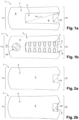
- THE figures 1a-b show respectively a top view of the medicine case according to the present invention without display device, without blister and with display device, with blister.
- THE figures 2a-b respectively show a bottom view of the medicine case according to the present invention without the blister, with mounting screws and with the blister, without mounting screws.
- picture 3 is a side view of the medicine case according to the present invention.
- FIG. 4 is a rear view of the closed end of the medicine case according to the present invention.
- THE figures 5a-b are a front view and show an open end view of the medicine case according to the present invention without and with the blister, respectively.
- FIG 6 is a partial cross-sectional view of the medicine case according to the present invention, taken along line AA of the figure 1b .
- the figures 1a and 1b illustrate a medicine case 1 according to the present invention arranged to house a removable blister 2 provided with a series of medicines 3.
- the medicine case 1 comprises a bottom wall 4 having a radius of curvature ⁇ 0, preferably concave ( of concavity upwards) which has a first outer face 5 and a second inner face 6 and a sky wall 7 having a radius of curvature ⁇ 0, preferably concave (of concavity upwards) which has a first inner face 8 and a second outer face 9.
- the first outer face 5 of the bottom wall 4 is convex, the second inner face 6 of the bottom wall 4 is concave.
- the first inner face 8 of the canopy wall 7 is convex
- the second outer face 9 of the canopy wall 7 is convex
- cave is understood to mean, within the meaning of the present invention, a hollow surface, either of a rounded shape towards the inside.
- convex is understood to mean, within the meaning of the present invention, a domed surface, ie of a rounded shape towards the outside.
- the bottom wall 4 and the sky wall 7 are of complementary curved shape so as to form a case 1 which is arranged to receive the removable blister 2 between the bottom wall 4 and the sky wall 7, which are at least partially connected to each other on one side.
- the case 1 comprises on the one hand a closed end 11 in contact with a bonded end of the bottom wall 4 and a bonded end of the sky wall 7, and on the other hand an open end 12 forming a mouth opposite to the closed end 11.
- the periphery of said mouth is in contact with the free end of the bottom wall 4 and the free end of the sky wall 7.
- the closed end 11 of the case 1 is fitted with an electronic monitoring device 13 which makes it possible to generate data indicative of the taking of the drug on the basis of event captures.
- the open end 12 forms a mouth arranged to insert and/or remove the removable blister 2 between the bottom wall 4 and the sky wall 7.
- Sky wall 7 has a first longitudinal cut forming a first slot 14 from a free end of sky wall 7.
- the bottom wall 4 has a second longitudinal cutout forming a second slot 15 from a free end of the bottom wall 4 at the level of the open end 12 of the case 1.
- the first slot 14 and the second slot 15 are superimposed one above the other and form the mouth with the open end of the case 1.
- first slot 14 and the second slot 15 superimposed on top of each other and allow the patient to grasp the removable blister 2 by passing a first finger through the first slot 14 and a second finger through the second slot 15 in order to remove the removable blister 2 from the medicine case 1.
- the electronic monitoring device 13 placed on the case 1 comprises a sensor, a memory which makes it possible to record the date and time of the captured event, a processor and a display device 16, preferably the display device 16 is an LCD screen.
- the processor is arranged to process the events captured and emit a signal comprising the data indicative of the taking of medication, these data can possibly be displayed on the display device 16 of the electronic monitoring device 13.
- the sensor identifies the introduction and / or removal of the removable blister 2.
- the sensor of the electronic monitoring device 13 will detect the end of the blister, for example by contact, and when the patient removes the removable blister 2 to take a a drug, the contact between the end of the blister and the sensor of the electronic monitoring device 13 is broken.
- the sensor emits a signal which is stored in the memory, this signal is processed by the processor to generate data indicative of the taking of said one or more medication(s).
- the events and indicative data can be the time, the date or the count or more elaborate data processed by one or more processors. These events and indicative data are collected and processed in a processor separate from the medicine case 1 or in certain cases the events or indicative data can be reintroduced by any type of communication means into the connected medicine case 1.
- THE figures 2a and 2b illustrate a view from below of the medicine case 1 which shows the outer face 5 of the bottom wall 4 and the second slot 15 from a free end of the bottom wall 4 without the removable blister 2 ( figure 2a ) and with the removable blister 2 ( figure 2b ).
- FIG. 3 illustrates a side view of the medicine case 1 which has the first outer face 5 of the bottom wall 4 and the second outer face 9 of the sky wall 7 which are at least partially connected to each other on a perimeter.
- FIG. 4 illustrates the closed end 11 of the medicine case 1 in contact with a bonded end of the bottom wall 4 and a bonded end of the sky wall 7.
- the bonded end of the bottom wall 4 and the bonded end of the sky wall 7 are for example produced by injection molding and the closed end 11 of the case 1 is obtained by pinching the bonded end of the bottom wall 4 and of the linked end of the top wall 7 on one periphery.
- THE figures 5a and 5b illustrate a view of the open end 12 of the medicine case 1 where one sees the free end of the bottom wall 4 and the free end of the top wall 7.
- the open end 12 forms with the first slot 14 of the sky wall 7 and the second slot 15 of the bottom wall 4 the mouth of the case 1.
- the bottom wall 4 comprises at least two lugs 17 arranged on either side of the second slot 15 and which extend from the inner face 6 of the bottom wall 4 in the direction of the sky wall 7.
- the at least two lugs 17 are used to hold the removable blister 2 when it is inserted into the drug case 1.
- the presence of the at least two lugs 17 of height greater than a thickness of the removable blister 2 allows the removable blister 2 to remain in its inserted position, even when the medicine case 1 is shocked or accidentally dropped.
- the at least two lugs 17 have a height of at least 0.3 mm, preferentially of at least 0.6 mm, advantageously of at least 0.8 mm, particularly advantageously at least 1.0 mm, preferably at least 1.2 mm, advantageously at least 1.4 mm, preferably at least 1.6 mm.
- the sky wall 7 comprises at least two transverse walls 18 which extend substantially parallel to the longitudinal direction l of the medicine case 1.
- the at least two transverse walls 18 are arranged on either side of the first slot 14 and extend from the first inner face 8 of the sky wall 7 towards the bottom wall 4.
- the at least two transverse walls 18 make it possible to maintain the removable blister 2 in its position against the bottom wall 4 and in abutment of the two lugs 17.
- the at least two transverse walls 18 are arranged to partially force contact of said removable blister 2 against said bottom wall 4.
- the contact takes place on a surface starting from the end of the blister opposite that which is visible through said mouth of case 1, of at least 50% of said removable blister 2, preferably of at least 60%, preferentially of at least 70%, advantageously of at least least 80%, preferably at least 90% relative to the total surface of said removable blister 2.
- the at least two transverse walls 18 make it possible to force a contact of the removable blister 2 against the bottom wall 4 in order to maintain it correctly in its position inserted in the case 1 over a large surface, against the bottom wall 4 , against the at least two lugs 17 and so as to make reliable contact with the electronic monitoring device 13 in order to prevent false positive events while helping to guide the removable blister 2 as it enters the medicine case 1 so that it is detected by the device monitoring electronics 13 and reducing its deformation.
- FIG 6 is a sectional view of the medicine case 1 according to the present invention, according to the line AA of the figure 1b , illustrating the removable blister 2, the convex outer face 5 and the concave inner face 6 of the bottom wall 4, the convex inner face 8 and the concave outer face 9 of the top wall 7, the at least two lugs 17, the at least two transverse walls 18 and the side walls 19 of the case 1.
- the removable blister 2 in its inserted position in the medicine case 1 abuts the at least two lugs 17 so as to be blocked in its position in contact with the electronic monitoring device 13.
- the presence of at least two transverse walls 18 makes it possible to maintain the removable blister 2 in its position against the bottom wall 4 and thus in a correct positioning with the electronic monitoring device 13 reducing the detection of false positive events during a shock or an drop of medicine case 1.
- the patient When removing the removable blister 2 from the case 1, the patient will pinch the end of the removable blister 2 accessible between the first slot 14 of the sky wall 7 and the second slot 15 of the bottom wall 4 then lift the removable blister 2 above the at least two lugs 17 to slide the latter out of the medicine case 1.
- contact with the electronic monitoring device 13 is broken and it then captures an event related to taking medication.
- the at least two lugs 17 extend along a first plane having an intersection with a second plane tangent to the bottom wall 4, on which intersection is positioned transversely the center of a landmark trigonometric, whose cosine axis is inscribed in said second plane, said first plane forming an angle of inclination of said at least two lugs 17 with said second tangent plane having a sine greater than or equal to 0.5, or even greater than or equal to 0.7, preferably having a cosine between 0 and -0.5, preferably between 0 and -0.3.
- the at least two lugs 17 make it possible to block the removable blister 2 inside the medicine case 1, which reduces the detection of false positive events while facilitating the removal of the removable blister 2 from the medicine case 1 when the cosine is between 0 and -0.5, more particularly between 0 and -0.3 as well as by reducing the deformation of the removable blister 2.
- drugs 1 according to the present invention is preferably produced by injection molding.
- the orientation of the at least two lugs 17 facilitates demolding and thus avoids the scrapping of parts whose lugs 17 would be damaged on demolding.
- the at least two transverse walls 18 have a first longitudinal edge 20 and a second longitudinal edge 21 and two transverse edges 22, 23.
- the first transverse edge 22 is located close to the closed end 11 of the case 1.
- the second transverse edge 23 is located close to the open end 12 of the case 1 and forms a free edge which extends between the two longitudinal edges 20, 21. Also, the second transverse edge 23 is longer than the length of the first transverse edge 22.
- first longitudinal edge 20 in contact with the inner face 8 of the sky wall 7 is longer than the second longitudinal edge 21 opposite and substantially parallel to the first longitudinal edge 20, by at least 5 mm, preferably at least 10mm, more particularly at least 15mm and at most 30mm, preferably at most 25mm, more particularly at most 20mm.
- said second transverse edge 23 can thus be rounded, parabolic, elliptical or even inclined and allows easy passage of the removable blister 2 during the introduction and / or removal of the latter from the case for drugs 1.
- a first space 24 is formed between said inner face 6 of the bottom wall 4 and each of the at least two transverse walls 18, where the smaller distance between the inner face 6 of the bottom wall 4 and the second longitudinal edge 21 is at least 0.4 mm, preferably at least 0.6 mm, advantageously at least 0.8 mm, particularly advantageously at least 1, 0 mm, preferably at least 1.2 mm, advantageously at least 1.4 mm, preferably at least 1.6 mm and at most 3.0 mm, preferably at most 2.6 mm, preferably at most 2.2 mm, advantageously at most 1.8 mm.
- a second space 25 is formed between the at least two lugs 17 and the second transverse edge of each of the at least two transverse walls 18, where the smallest distance between any point of the at least two lugs and said second transverse edge of the at least two transverse walls is at least 0.3 mm, preferably at least 0.4 mm, preferably at least 0.5 mm, advantageously at least 0 .6 mm, advantageously at least 0.7 mm, particularly advantageously at least 0.8 mm, particularly at least 0.9 mm and at most 2.0 mm, preferably at most 1.8 mm, preferably at most 1.6 mm, preferentially at most 1.4 mm, advantageously at most 1.2 mm.
- the medicine case 1 can be made of one or more materials such as, for example, wood, cardboard, paper, plastic, metal, polymers.
- the medication case 1 is used to measure a patient's adherence to a prescribed dosage.
- the two lugs can form a front face of the drawer.
Landscapes
- Health & Medical Sciences (AREA)
- Engineering & Computer Science (AREA)
- Life Sciences & Earth Sciences (AREA)
- Animal Behavior & Ethology (AREA)
- General Health & Medical Sciences (AREA)
- Public Health (AREA)
- Veterinary Medicine (AREA)
- Medical Informatics (AREA)
- Pharmacology & Pharmacy (AREA)
- Bioinformatics & Cheminformatics (AREA)
- Medical Preparation Storing Or Oral Administration Devices (AREA)
Claims (13)
- Etui für Arzneimittel (1), angeordnet, um einen entfernbaren Blister (2) unterzubringen, der mit einer Reihe von Arzneimitteln (3) versehen ist, und umfassend:- eine Bodenwand (4), die eine erste konvexe Außenseite (5) und eine zweite konkave Innenseite (6) aufweist,- eine obere Wand (7), die eine erste konvexe Innenseite (8) und eine zweite konkave Außenseite (9) aufweist,- wobei die Bodenwand (4) und die obere Wand (7) in einer ergänzenden gebogenen Form sind, um ein Etui (1) zu bilden, das angeordnet ist, um den entfernbaren Blister (2) zwischen der Bodenwand (4) und der oberen Wand (7) aufzunehmen; wobei die Bodenwand (4) und die obere Wand (7) mindestens teilweise an einem Umfang miteinander verbunden sind,- wobei das Etui (1) ein geschlossenes Ende (11) umfasst, das mit einer elektronischen Überwachungsvorrichtung (13) versehen ist, um Daten zu generieren, die die Einnahme des einen oder mehrerer Arzneimittel (3) auf Grundlage einer Erfassung von Ereignissen in Kontakt mit einem verbundenen Ende der Bodenwand (4) und einem verbundenen Ende der oberen Wand (7) anzeigen, und ein offenes Ende (12) gegenüber dem geschlossenen Ende (11), das einen Durchlass bildet, der angeordnet ist, um den entfernbaren Blister (2) zwischen der Bodenwand (4) und der oberen Wand (7) einzuführen und/oder zu entnehmen,- wobei die obere Wand (7) einen ersten länglichen Ausschnitt aufweist, der einen ersten Schlitz (14) ausgehend von einem freien Ende der oberen Wand (7) gegenüber dem verbundenen Ende bildet,(i) dadurch gekennzeichnet, dass die Bodenwand (4) einen zweiten Ausschnitt aufweist, der einen zweiten Schlitz (15) ausgehend von einem freien Ende gegenüber dem verbundenen Ende im Bereich des offenen Endes (12) des Etuis (1) bildet, wobei der erste Schlitz (14) und der zweite Schlitz (15) einer über den anderen überlagert sind und den Durchlass mit dem offenen Ende (12) des Etuis (1) bilden, (ii) dadurch, dass die Bodenwand (4) mindestens zwei Zapfen (17) mit einer Höhe größer als eine Dicke des Blisters (2) umfasst, von denen jeder beiderseits des zweiten Schlitzes (15) angeordnet ist, und sich von der Innenseite (6) in Richtung der oberen Wand (7) erstreckt, (iii) und dadurch, dass die obere Wand (7) mit mindestens zwei quer laufenden Wänden (18) im Wesentlichen parallel zur Längsrichtung (I) versehen ist, wobei jede der beiden querlaufenden Wände (18) beiderseits des ersten Schlitzes (14) angeordnet ist, wobei sich die mindestens zwei quer laufenden Wände (18) von der Innenseite (8) der oberen Wand (7) in Richtung der Bodenwand (4) erstrecken.
- Etui für Arzneimittel (1) nach Anspruch 1, wobei sich die mindestens zwei Zapfen (17) über eine erste Ebene erstrecken, die eine Überschneidung mit einer zweiten Ebene tangential zur Bodenwand (4) aufweist, wobei auf der Überschneidung quer laufend das Zentrum eines trigonometrischen Bezugspunktes positioniert ist, dessen Kosinus-Achse in der zweiten Ebene eingeschrieben ist, wobei die erste Ebene einen Neigungswinkel der mindestens zwei Zapfen (17) mit der zweiten tangentialen Ebene bildet, die einen Sinus größer oder gleich 0,5, oder gar größer oder gleich 0,7 aufweist, vorzugsweise einen Kosinus aufweist, der zwischen 0 und -0,5, vorzugsweise zwischen 0 und -0,3 liegt.
- Etui für Arzneimittel (1) nach einem der Ansprüche 1 oder 2, wobei die mindestens zwei Zapfen (17) eine Höhe von mindestens 0,3 mm, vorzugsweise mindestens 0,6 mm, in vorteilhafter Weise mindestens 0,8 mm, in besonders vorteilhafter Weise mindestens 1,0 mm, bevorzugt 1,2 mm, in vorteilhafter Weise mindestens 1,4 mm, bevorzugt mindestens 1,6 mm aufweist.
- Etui für Arzneimittel (1) nach einem der vorstehenden Ansprüche, wobei die mindestens zwei quer laufenden Wände (18) angeordnet sind, um teilweise einen Kontakt des Blisters (2) an der Bodenwand (4) zu erzwingen, und der Kontakt auf einer Oberfläche ab dem Ende des Blisters entgegengesetzt zu jenem, das durch den Durchlass hindurch zu mindestens 50% des Blisters, vorzugsweise mindestens zu 60%, bevorzugt mindestens zu 70%, in vorteilhafter Weise mindestens zu 80%, bevorzugt mindestens zu 90% in Bezug auf die gesamte Oberfläche des Blisters sichtbar ist, stattfindet.
- Etui für Arzneimittel (1) nach einem der vorstehenden Ansprüche, wobei die mindestens zwei quer laufenden Wände (18) einen ersten (20) und einen zweiten (21) längs gerichteten Grat, und zwei quer gerichtete Grate (22, 23) aufweisen, wobei sich der erste quer gerichtete Grat (22) in der Nähe des geschlossenen Endes (11) des Etuis (1) befindet, während sich der zweite quer gerichtete Grat (23) im Bereich des offenen Endes (12) des Etuis (1) befindet, und einen freien Grat bildet, die sich zwischen den beiden längs gerichteten Graten (20, 21) erstreckt, und eine Länge größer als der erste quer gerichtete Grat (22) aufweist, wobei der erste längs gerichtete Grat (20) in Kontakt mit der Innenseite (8) der oberen Wand (7) länger als der zweite längs gerichtete Grat (21) gegenüber und im Wesentlichen parallel zum ersten längs gerichteten Grat (20) ist.
- Etui für Arzneimittel (1) nach Anspruch 5, wobei die Länge des ersten längs gerichteten Grats (20) um mindestens 5 mm, vorzugsweise mindestens 10 mm, ganz besonders um mindestens 15 mm und höchstens 30 mm, vorzugsweise höchstens 25 mm, ganz besonders um höchstens 20 mm größer als die Länge des zweiten längs gerichteten Grats (21) ist.
- Etui für Arzneimittel (1) nach einem der vorstehenden Ansprüche, wobei ein erster Raum (24) zwischen der Innenseite (6) der Bodenwand (4) und jeder der mindestens zwei quer laufenden Wände (18) gebildet wird, wobei der kleinste Abstand zwischen der Innenseite (6) der Bodenwand (4) und dem zweiten längs gerichteten Grat (21) mindestens 0,4 mm, bevorzugt mindestens 0,6 mm, in vorteilhafter Weise mindestens 0,8 mm, in besonders vorteilhafter Weise mindestens 1,0 mm, in bevorzugter Weise mindestens 1,2 mm, in vorteilhafter Weise mindestens 1,4 mm, in bevorzugter Weise 1,6 mm und höchstens 3,0 mm, vorzugsweise höchstens 2,6 mm, in bevorzugter Weise höchstens 2,2 mm, in vorteilhafter Weise höchstens 1,8 mm beträgt.
- Etui für Arzneimittel (1) nach einem der vorstehenden Ansprüche, wobei ein zweiter Raum (25) zwischen den mindestens zwei Zapfen (17) und dem zweiten quer gerichteten Grat (23) einer jeden der mindestens zwei quer laufenden Wände (18) gebildet wird, wobei der kleinste Abstand zwischen irgendeinem Punkt der mindestens zwei Zapfen (17) und dem zweiten quer gerichteten Grat (23) der mindestens zwei quer laufenden Wände (18) mindestens 0,3 mm, bevorzugt mindestens 0,4 mm, vorzugsweise mindestens 0,5 mm, in vorteilhafter Weise mindestens 0,6 mm, in vorteilhafter Weise mindestens 0,7 mm, in besonders vorteilhafter Weise mindestens 0,8 mm, ganz besonders mindestens 0,9 mm und höchstens 2,0 mm, bevorzugt höchstens 1,8 mm, in bevorzugter Weise höchstens 1,6 mm, bevorzugt höchstens 1,4 mm, in vorteilhafter Weise höchstens 1,2 mm beträgt.
- Etui für Arzneimittel (1) nach einem der vorstehenden Ansprüche, wobei die elektronische Überwachungsvorrichtung (13) weiter einen Prozessor und eventuell eine Anzeigevorrichtung (16), bevorzugt einen LCD-Bildschirm umfasst, wobei der Prozessor angeordnet ist, um die erfassten Ereignisse zu behandeln und die Daten auszugeben, die die Einnahme des oder mehrerer Arzneimittel(s) anzeigen, wobei die anzeigenden Daten eventuell auf der Anzeigevorrichtung (16) angezeigt werden.
- Etui für Arzneimittel (1) nach einem der vorstehenden Ansprüche, wobei die elektronische Überwachungsvorrichtung (13) einen Speicher umfasst, der angeordnet ist, um das Datum und die Uhrzeit des erfassten Ereignisses zu speichern.
- Etui für Arzneimittel (1) nach einem der Ansprüche, welches aus einem oder mehreren Werkstoffen gefertigt sein kann, die unabhängig voneinander aus der Gruppe ausgewählt werden, die aus Holz, Karton, Papier, Kunststoff, Metall, Polymeren besteht.
- Etui für Arzneimittel (1) nach einem der Ansprüche, wobei mindestens zwei Seitenwände (19), die Bodenwand (4) und die mindestens zwei Zapfen (17) eine Schublade bilden, die gleitend in dem Etui (1) aufgenommen ist.
- Etui für Arzneimittel (1) nach Anspruch 12, weiter ein System zum Blockieren der gleitend aufgenommenen Schublade umfassend, das angeordnet ist, um ein Öffnen zu verhindern, das von einem Kind durchgeführt wird.
Applications Claiming Priority (2)
| Application Number | Priority Date | Filing Date | Title |
|---|---|---|---|
| BE20185357A BE1026332B1 (fr) | 2018-05-30 | 2018-05-30 | Etui pour medicaments |
| PCT/EP2019/063961 WO2019229123A1 (fr) | 2018-05-30 | 2019-05-29 | Etui pour medicaments |
Publications (2)
| Publication Number | Publication Date |
|---|---|
| EP3801436A1 EP3801436A1 (de) | 2021-04-14 |
| EP3801436B1 true EP3801436B1 (de) | 2023-06-28 |
Family
ID=62567172
Family Applications (1)
| Application Number | Title | Priority Date | Filing Date |
|---|---|---|---|
| EP19730270.6A Active EP3801436B1 (de) | 2018-05-30 | 2019-05-29 | Etui für arzneimittel |
Country Status (4)
| Country | Link |
|---|---|
| EP (1) | EP3801436B1 (de) |
| JP (1) | JP2021526067A (de) |
| BE (1) | BE1026332B1 (de) |
| WO (1) | WO2019229123A1 (de) |
Families Citing this family (1)
| Publication number | Priority date | Publication date | Assignee | Title |
|---|---|---|---|---|
| DE102017103161B4 (de) | 2017-02-16 | 2018-11-29 | Kathrein Se | Antennenvorrichtung und Antennenarray |
Family Cites Families (7)
| Publication number | Priority date | Publication date | Assignee | Title |
|---|---|---|---|---|
| JP2005518871A (ja) * | 2002-03-07 | 2005-06-30 | バング・オ・オルフセン・メディコム・アクティーゼルスカブ | 医療用ディスペンサ、ディスペンサで使用されるブリスタカードおよび服用量の医薬の分与方法 |
| US7475783B2 (en) | 2003-04-30 | 2009-01-13 | Bang & Olufsen Medicom, A/S | Dispenser for holding a means for holding a plurality of units for dispensing, and a method for operating the dispenser |
| EP2107011A1 (de) * | 2008-03-31 | 2009-10-07 | MeadWestvaco Corporation | Verbesserte Blisterpackung-Zweitverpackung und Hülse |
| DE112009001748T5 (de) * | 2008-07-18 | 2012-01-12 | Meadwastvaco Corporation | Verpackung zur Befestigung einer Bilsterverpackung |
| WO2012178075A2 (en) * | 2011-06-24 | 2012-12-27 | Abbott Laboratories | Tamper-evident packaging |
| CN202409480U (zh) * | 2011-12-31 | 2012-09-05 | 上海物鼎传感技术有限公司 | 一种智能电子药盒装置 |
| US10058485B2 (en) * | 2014-03-03 | 2018-08-28 | Manrex Pty. Ltd. | Improvements relating to blister package compliance |
-
2018
- 2018-05-30 BE BE20185357A patent/BE1026332B1/fr active IP Right Grant
-
2019
- 2019-05-29 EP EP19730270.6A patent/EP3801436B1/de active Active
- 2019-05-29 WO PCT/EP2019/063961 patent/WO2019229123A1/fr not_active Ceased
- 2019-05-29 JP JP2021517517A patent/JP2021526067A/ja active Pending
Also Published As
| Publication number | Publication date |
|---|---|
| JP2021526067A (ja) | 2021-09-30 |
| BE1026332A1 (fr) | 2020-01-06 |
| WO2019229123A1 (fr) | 2019-12-05 |
| EP3801436A1 (de) | 2021-04-14 |
| BE1026332B1 (fr) | 2020-01-13 |
Similar Documents
| Publication | Publication Date | Title |
|---|---|---|
| EP1095605B1 (de) | Auswurfvorrichtung für Kartusche | |
| EP0827732A1 (de) | Modulare Medikamentenspendervorrichtung im Taschenformat | |
| EP2463205B1 (de) | Automatisierte Vorrichtung für die Herstellung von Produktlosen aus in Blister verpackten Produkten, insbesondere Medikamente | |
| FR2589840A1 (fr) | Conteneur et procede pour charger des billets de banque dans une cassette a billets | |
| BE1026332B1 (fr) | Etui pour medicaments | |
| EP2699129A1 (de) | Maschine zur zubereitung eines getränks | |
| FR3050932A1 (fr) | Dispositif et procede d'emballage de medicaments solides, dispositif de stockage et de distribution de tels medicaments et procede de distribution | |
| FR2970645A1 (fr) | Systeme automatise de dose unitaire pour la delivrance nominative de medicaments | |
| BE1026328A1 (fr) | Emballage pour medicaments | |
| EP2665458A1 (de) | Automatisiertes dosissystem zur portionierten abgabe von medikamenten | |
| FR2944696A1 (fr) | Dispositif de mesure de l'observance du suivi d'un medicament sous blister | |
| EP0470919A1 (de) | Dosierspender, insbesondere für homöopatische Arzneimittel, Pillen, Lutschpastillen und andere ähnliche Produkte | |
| US20230080576A1 (en) | Medicine Dispenser with Patient Compliance Monitoring System | |
| WO2018078093A1 (fr) | Ensemble, dispositifs et procédé de préparation et de distribution de médicaments en piluliers | |
| FR2957623A1 (fr) | Serrure avec cle | |
| EP3706703A1 (de) | Vorrichtung zum laden/verteilen von objekten in einen lagerbehälter für solche objekte, verwendungen solch einer vorrichtung und verfahren zum laden und verteilen | |
| BE1026661B1 (fr) | Systeme de suivi d'un comportement lie a la sante | |
| EP3395319B1 (de) | Vorrichtung zum verpacken von festen medikamenten, lager- und ausgabevorrichtung, und ausgabeverfahren von diesen medikamenten | |
| EP3622940B1 (de) | Gehäuse für die aufbewahrung und abgabe von zu verabreichenden arzneimitteln | |
| JP2014171847A (ja) | 薬剤取り出し具 | |
| EP3536299A1 (de) | Medikamenten-ausgabevorrichtung für die therapeutische behandlung eines einzigen patienten | |
| BE1024857B1 (fr) | Accessoire pour dispositif electronique de type telephone mobile | |
| FR2971420A3 (fr) | Boite de recharge de medicaments | |
| JP2023085650A5 (de) | ||
| WO1995028142A1 (fr) | Appareil distributeur automatique de medicaments en forme de gelules ou de pilules avec autonomie hebdomadaire et alarme auditive |
Legal Events
| Date | Code | Title | Description |
|---|---|---|---|
| STAA | Information on the status of an ep patent application or granted ep patent |
Free format text: STATUS: UNKNOWN |
|
| STAA | Information on the status of an ep patent application or granted ep patent |
Free format text: STATUS: THE INTERNATIONAL PUBLICATION HAS BEEN MADE |
|
| PUAI | Public reference made under article 153(3) epc to a published international application that has entered the european phase |
Free format text: ORIGINAL CODE: 0009012 |
|
| STAA | Information on the status of an ep patent application or granted ep patent |
Free format text: STATUS: REQUEST FOR EXAMINATION WAS MADE |
|
| 17P | Request for examination filed |
Effective date: 20201130 |
|
| AK | Designated contracting states |
Kind code of ref document: A1 Designated state(s): AL AT BE BG CH CY CZ DE DK EE ES FI FR GB GR HR HU IE IS IT LI LT LU LV MC MK MT NL NO PL PT RO RS SE SI SK SM TR |
|
| AX | Request for extension of the european patent |
Extension state: BA ME |
|
| DAV | Request for validation of the european patent (deleted) | ||
| DAX | Request for extension of the european patent (deleted) | ||
| STAA | Information on the status of an ep patent application or granted ep patent |
Free format text: STATUS: EXAMINATION IS IN PROGRESS |
|
| 17Q | First examination report despatched |
Effective date: 20220222 |
|
| GRAP | Despatch of communication of intention to grant a patent |
Free format text: ORIGINAL CODE: EPIDOSNIGR1 |
|
| STAA | Information on the status of an ep patent application or granted ep patent |
Free format text: STATUS: GRANT OF PATENT IS INTENDED |
|
| INTG | Intention to grant announced |
Effective date: 20230126 |
|
| GRAS | Grant fee paid |
Free format text: ORIGINAL CODE: EPIDOSNIGR3 |
|
| GRAA | (expected) grant |
Free format text: ORIGINAL CODE: 0009210 |
|
| STAA | Information on the status of an ep patent application or granted ep patent |
Free format text: STATUS: THE PATENT HAS BEEN GRANTED |
|
| AK | Designated contracting states |
Kind code of ref document: B1 Designated state(s): AL AT BE BG CH CY CZ DE DK EE ES FI FR GB GR HR HU IE IS IT LI LT LU LV MC MK MT NL NO PL PT RO RS SE SI SK SM TR |
|
| P01 | Opt-out of the competence of the unified patent court (upc) registered |
Effective date: 20230524 |
|
| REG | Reference to a national code |
Ref country code: CH Ref legal event code: EP |
|
| REG | Reference to a national code |
Ref country code: AT Ref legal event code: REF Ref document number: 1582089 Country of ref document: AT Kind code of ref document: T Effective date: 20230715 |
|
| REG | Reference to a national code |
Ref country code: IE Ref legal event code: FG4D Free format text: LANGUAGE OF EP DOCUMENT: FRENCH |
|
| REG | Reference to a national code |
Ref country code: DE Ref legal event code: R096 Ref document number: 602019031718 Country of ref document: DE |
|
| REG | Reference to a national code |
Ref country code: LT Ref legal event code: MG9D |
|
| PG25 | Lapsed in a contracting state [announced via postgrant information from national office to epo] |
Ref country code: SE Free format text: LAPSE BECAUSE OF FAILURE TO SUBMIT A TRANSLATION OF THE DESCRIPTION OR TO PAY THE FEE WITHIN THE PRESCRIBED TIME-LIMIT Effective date: 20230628 Ref country code: NO Free format text: LAPSE BECAUSE OF FAILURE TO SUBMIT A TRANSLATION OF THE DESCRIPTION OR TO PAY THE FEE WITHIN THE PRESCRIBED TIME-LIMIT Effective date: 20230928 |
|
| REG | Reference to a national code |
Ref country code: NL Ref legal event code: MP Effective date: 20230628 |
|
| REG | Reference to a national code |
Ref country code: AT Ref legal event code: MK05 Ref document number: 1582089 Country of ref document: AT Kind code of ref document: T Effective date: 20230628 |
|
| PG25 | Lapsed in a contracting state [announced via postgrant information from national office to epo] |
Ref country code: RS Free format text: LAPSE BECAUSE OF FAILURE TO SUBMIT A TRANSLATION OF THE DESCRIPTION OR TO PAY THE FEE WITHIN THE PRESCRIBED TIME-LIMIT Effective date: 20230628 Ref country code: NL Free format text: LAPSE BECAUSE OF FAILURE TO SUBMIT A TRANSLATION OF THE DESCRIPTION OR TO PAY THE FEE WITHIN THE PRESCRIBED TIME-LIMIT Effective date: 20230628 Ref country code: LV Free format text: LAPSE BECAUSE OF FAILURE TO SUBMIT A TRANSLATION OF THE DESCRIPTION OR TO PAY THE FEE WITHIN THE PRESCRIBED TIME-LIMIT Effective date: 20230628 Ref country code: LT Free format text: LAPSE BECAUSE OF FAILURE TO SUBMIT A TRANSLATION OF THE DESCRIPTION OR TO PAY THE FEE WITHIN THE PRESCRIBED TIME-LIMIT Effective date: 20230628 Ref country code: HR Free format text: LAPSE BECAUSE OF FAILURE TO SUBMIT A TRANSLATION OF THE DESCRIPTION OR TO PAY THE FEE WITHIN THE PRESCRIBED TIME-LIMIT Effective date: 20230628 Ref country code: GR Free format text: LAPSE BECAUSE OF FAILURE TO SUBMIT A TRANSLATION OF THE DESCRIPTION OR TO PAY THE FEE WITHIN THE PRESCRIBED TIME-LIMIT Effective date: 20230929 |
|
| PG25 | Lapsed in a contracting state [announced via postgrant information from national office to epo] |
Ref country code: FI Free format text: LAPSE BECAUSE OF FAILURE TO SUBMIT A TRANSLATION OF THE DESCRIPTION OR TO PAY THE FEE WITHIN THE PRESCRIBED TIME-LIMIT Effective date: 20230628 |
|
| PG25 | Lapsed in a contracting state [announced via postgrant information from national office to epo] |
Ref country code: SK Free format text: LAPSE BECAUSE OF FAILURE TO SUBMIT A TRANSLATION OF THE DESCRIPTION OR TO PAY THE FEE WITHIN THE PRESCRIBED TIME-LIMIT Effective date: 20230628 |
|
| PG25 | Lapsed in a contracting state [announced via postgrant information from national office to epo] |
Ref country code: ES Free format text: LAPSE BECAUSE OF FAILURE TO SUBMIT A TRANSLATION OF THE DESCRIPTION OR TO PAY THE FEE WITHIN THE PRESCRIBED TIME-LIMIT Effective date: 20230628 |
|
| PG25 | Lapsed in a contracting state [announced via postgrant information from national office to epo] |
Ref country code: IS Free format text: LAPSE BECAUSE OF FAILURE TO SUBMIT A TRANSLATION OF THE DESCRIPTION OR TO PAY THE FEE WITHIN THE PRESCRIBED TIME-LIMIT Effective date: 20231028 |
|
| PG25 | Lapsed in a contracting state [announced via postgrant information from national office to epo] |
Ref country code: SM Free format text: LAPSE BECAUSE OF FAILURE TO SUBMIT A TRANSLATION OF THE DESCRIPTION OR TO PAY THE FEE WITHIN THE PRESCRIBED TIME-LIMIT Effective date: 20230628 Ref country code: SK Free format text: LAPSE BECAUSE OF FAILURE TO SUBMIT A TRANSLATION OF THE DESCRIPTION OR TO PAY THE FEE WITHIN THE PRESCRIBED TIME-LIMIT Effective date: 20230628 Ref country code: RO Free format text: LAPSE BECAUSE OF FAILURE TO SUBMIT A TRANSLATION OF THE DESCRIPTION OR TO PAY THE FEE WITHIN THE PRESCRIBED TIME-LIMIT Effective date: 20230628 Ref country code: PT Free format text: LAPSE BECAUSE OF FAILURE TO SUBMIT A TRANSLATION OF THE DESCRIPTION OR TO PAY THE FEE WITHIN THE PRESCRIBED TIME-LIMIT Effective date: 20231030 Ref country code: IS Free format text: LAPSE BECAUSE OF FAILURE TO SUBMIT A TRANSLATION OF THE DESCRIPTION OR TO PAY THE FEE WITHIN THE PRESCRIBED TIME-LIMIT Effective date: 20231028 Ref country code: ES Free format text: LAPSE BECAUSE OF FAILURE TO SUBMIT A TRANSLATION OF THE DESCRIPTION OR TO PAY THE FEE WITHIN THE PRESCRIBED TIME-LIMIT Effective date: 20230628 Ref country code: EE Free format text: LAPSE BECAUSE OF FAILURE TO SUBMIT A TRANSLATION OF THE DESCRIPTION OR TO PAY THE FEE WITHIN THE PRESCRIBED TIME-LIMIT Effective date: 20230628 Ref country code: CZ Free format text: LAPSE BECAUSE OF FAILURE TO SUBMIT A TRANSLATION OF THE DESCRIPTION OR TO PAY THE FEE WITHIN THE PRESCRIBED TIME-LIMIT Effective date: 20230628 Ref country code: AT Free format text: LAPSE BECAUSE OF FAILURE TO SUBMIT A TRANSLATION OF THE DESCRIPTION OR TO PAY THE FEE WITHIN THE PRESCRIBED TIME-LIMIT Effective date: 20230628 |
|
| PG25 | Lapsed in a contracting state [announced via postgrant information from national office to epo] |
Ref country code: PL Free format text: LAPSE BECAUSE OF FAILURE TO SUBMIT A TRANSLATION OF THE DESCRIPTION OR TO PAY THE FEE WITHIN THE PRESCRIBED TIME-LIMIT Effective date: 20230628 |
|
| REG | Reference to a national code |
Ref country code: DE Ref legal event code: R097 Ref document number: 602019031718 Country of ref document: DE |
|
| PG25 | Lapsed in a contracting state [announced via postgrant information from national office to epo] |
Ref country code: DK Free format text: LAPSE BECAUSE OF FAILURE TO SUBMIT A TRANSLATION OF THE DESCRIPTION OR TO PAY THE FEE WITHIN THE PRESCRIBED TIME-LIMIT Effective date: 20230628 |
|
| PLBE | No opposition filed within time limit |
Free format text: ORIGINAL CODE: 0009261 |
|
| STAA | Information on the status of an ep patent application or granted ep patent |
Free format text: STATUS: NO OPPOSITION FILED WITHIN TIME LIMIT |
|
| PG25 | Lapsed in a contracting state [announced via postgrant information from national office to epo] |
Ref country code: IT Free format text: LAPSE BECAUSE OF FAILURE TO SUBMIT A TRANSLATION OF THE DESCRIPTION OR TO PAY THE FEE WITHIN THE PRESCRIBED TIME-LIMIT Effective date: 20230628 |
|
| 26N | No opposition filed |
Effective date: 20240402 |
|
| PG25 | Lapsed in a contracting state [announced via postgrant information from national office to epo] |
Ref country code: SI Free format text: LAPSE BECAUSE OF FAILURE TO SUBMIT A TRANSLATION OF THE DESCRIPTION OR TO PAY THE FEE WITHIN THE PRESCRIBED TIME-LIMIT Effective date: 20230628 |
|
| PG25 | Lapsed in a contracting state [announced via postgrant information from national office to epo] |
Ref country code: BG Free format text: LAPSE BECAUSE OF FAILURE TO SUBMIT A TRANSLATION OF THE DESCRIPTION OR TO PAY THE FEE WITHIN THE PRESCRIBED TIME-LIMIT Effective date: 20230628 |
|
| PG25 | Lapsed in a contracting state [announced via postgrant information from national office to epo] |
Ref country code: BG Free format text: LAPSE BECAUSE OF FAILURE TO SUBMIT A TRANSLATION OF THE DESCRIPTION OR TO PAY THE FEE WITHIN THE PRESCRIBED TIME-LIMIT Effective date: 20230628 |
|
| PG25 | Lapsed in a contracting state [announced via postgrant information from national office to epo] |
Ref country code: MC Free format text: LAPSE BECAUSE OF FAILURE TO SUBMIT A TRANSLATION OF THE DESCRIPTION OR TO PAY THE FEE WITHIN THE PRESCRIBED TIME-LIMIT Effective date: 20230628 |
|
| PG25 | Lapsed in a contracting state [announced via postgrant information from national office to epo] |
Ref country code: LU Free format text: LAPSE BECAUSE OF NON-PAYMENT OF DUE FEES Effective date: 20240529 |
|
| PG25 | Lapsed in a contracting state [announced via postgrant information from national office to epo] |
Ref country code: MC Free format text: LAPSE BECAUSE OF FAILURE TO SUBMIT A TRANSLATION OF THE DESCRIPTION OR TO PAY THE FEE WITHIN THE PRESCRIBED TIME-LIMIT Effective date: 20230628 Ref country code: LU Free format text: LAPSE BECAUSE OF NON-PAYMENT OF DUE FEES Effective date: 20240529 |
|
| PG25 | Lapsed in a contracting state [announced via postgrant information from national office to epo] |
Ref country code: IE Free format text: LAPSE BECAUSE OF NON-PAYMENT OF DUE FEES Effective date: 20240529 |
|
| PGFP | Annual fee paid to national office [announced via postgrant information from national office to epo] |
Ref country code: DE Payment date: 20250523 Year of fee payment: 7 |
|
| PGFP | Annual fee paid to national office [announced via postgrant information from national office to epo] |
Ref country code: GB Payment date: 20250520 Year of fee payment: 7 |
|
| PGFP | Annual fee paid to national office [announced via postgrant information from national office to epo] |
Ref country code: BE Payment date: 20250520 Year of fee payment: 7 |
|
| PGFP | Annual fee paid to national office [announced via postgrant information from national office to epo] |
Ref country code: FR Payment date: 20250519 Year of fee payment: 7 |
|
| PGFP | Annual fee paid to national office [announced via postgrant information from national office to epo] |
Ref country code: CH Payment date: 20250601 Year of fee payment: 7 |
|
| PG25 | Lapsed in a contracting state [announced via postgrant information from national office to epo] |
Ref country code: CY Free format text: LAPSE BECAUSE OF FAILURE TO SUBMIT A TRANSLATION OF THE DESCRIPTION OR TO PAY THE FEE WITHIN THE PRESCRIBED TIME-LIMIT; INVALID AB INITIO Effective date: 20190529 |
|
| PG25 | Lapsed in a contracting state [announced via postgrant information from national office to epo] |
Ref country code: HU Free format text: LAPSE BECAUSE OF FAILURE TO SUBMIT A TRANSLATION OF THE DESCRIPTION OR TO PAY THE FEE WITHIN THE PRESCRIBED TIME-LIMIT; INVALID AB INITIO Effective date: 20190529 |