EP3801080B1 - Détection de conditions de chauffage défavorables dans un système de génération d'aérosol chauffé électriquement - Google Patents
Détection de conditions de chauffage défavorables dans un système de génération d'aérosol chauffé électriquement Download PDFInfo
- Publication number
- EP3801080B1 EP3801080B1 EP19725729.8A EP19725729A EP3801080B1 EP 3801080 B1 EP3801080 B1 EP 3801080B1 EP 19725729 A EP19725729 A EP 19725729A EP 3801080 B1 EP3801080 B1 EP 3801080B1
- Authority
- EP
- European Patent Office
- Prior art keywords
- heating element
- aerosol
- heating
- heater
- temperature
- Prior art date
- Legal status (The legal status is an assumption and is not a legal conclusion. Google has not performed a legal analysis and makes no representation as to the accuracy of the status listed.)
- Active
Links
- 230000002411 adverse Effects 0.000 title claims description 42
- 239000000443 aerosol Substances 0.000 title description 34
- 238000001514 detection method Methods 0.000 title description 6
- 238000010438 heat treatment Methods 0.000 claims description 199
- 239000000758 substrate Substances 0.000 claims description 127
- 239000007788 liquid Substances 0.000 claims description 82
- 230000008859 change Effects 0.000 claims description 19
- 238000000034 method Methods 0.000 claims description 13
- 230000009467 reduction Effects 0.000 claims description 10
- 230000001276 controlling effect Effects 0.000 claims description 5
- 230000001105 regulatory effect Effects 0.000 claims description 4
- 238000004891 communication Methods 0.000 claims description 3
- 230000001007 puffing effect Effects 0.000 claims description 3
- 238000004590 computer program Methods 0.000 claims description 2
- 239000000463 material Substances 0.000 description 59
- 239000012071 phase Substances 0.000 description 13
- PEDCQBHIVMGVHV-UHFFFAOYSA-N Glycerine Chemical compound OCC(O)CO PEDCQBHIVMGVHV-UHFFFAOYSA-N 0.000 description 11
- 229920006395 saturated elastomer Polymers 0.000 description 11
- -1 aluminium- titanium- zirconium- Chemical compound 0.000 description 10
- 241000208125 Nicotiana Species 0.000 description 8
- 235000002637 Nicotiana tabacum Nutrition 0.000 description 8
- 239000003570 air Substances 0.000 description 7
- 238000012423 maintenance Methods 0.000 description 7
- 238000012544 monitoring process Methods 0.000 description 7
- DNIAPMSPPWPWGF-UHFFFAOYSA-N Propylene glycol Chemical compound CC(O)CO DNIAPMSPPWPWGF-UHFFFAOYSA-N 0.000 description 6
- 150000001875 compounds Chemical class 0.000 description 6
- 229910052751 metal Inorganic materials 0.000 description 6
- 239000002184 metal Substances 0.000 description 6
- 230000002829 reductive effect Effects 0.000 description 6
- 229910045601 alloy Inorganic materials 0.000 description 5
- 239000000956 alloy Substances 0.000 description 5
- 239000000919 ceramic Substances 0.000 description 5
- 235000019504 cigarettes Nutrition 0.000 description 5
- 239000000796 flavoring agent Substances 0.000 description 5
- 235000011187 glycerol Nutrition 0.000 description 5
- 230000003071 parasitic effect Effects 0.000 description 5
- 230000000704 physical effect Effects 0.000 description 5
- 239000010935 stainless steel Substances 0.000 description 5
- 229910001220 stainless steel Inorganic materials 0.000 description 5
- PUPZLCDOIYMWBV-UHFFFAOYSA-N (+/-)-1,3-Butanediol Chemical compound CC(O)CCO PUPZLCDOIYMWBV-UHFFFAOYSA-N 0.000 description 4
- 230000009471 action Effects 0.000 description 4
- 239000002131 composite material Substances 0.000 description 4
- 239000004744 fabric Substances 0.000 description 4
- 150000002739 metals Chemical class 0.000 description 4
- 230000000391 smoking effect Effects 0.000 description 4
- 238000003860 storage Methods 0.000 description 4
- OKTJSMMVPCPJKN-UHFFFAOYSA-N Carbon Chemical compound [C] OKTJSMMVPCPJKN-UHFFFAOYSA-N 0.000 description 3
- PXHVJJICTQNCMI-UHFFFAOYSA-N Nickel Chemical compound [Ni] PXHVJJICTQNCMI-UHFFFAOYSA-N 0.000 description 3
- 239000012080 ambient air Substances 0.000 description 3
- 235000019506 cigar Nutrition 0.000 description 3
- 238000005485 electric heating Methods 0.000 description 3
- 235000019634 flavors Nutrition 0.000 description 3
- 239000011888 foil Substances 0.000 description 3
- 238000003780 insertion Methods 0.000 description 3
- 230000037431 insertion Effects 0.000 description 3
- 230000007246 mechanism Effects 0.000 description 3
- 239000000203 mixture Substances 0.000 description 3
- BASFCYQUMIYNBI-UHFFFAOYSA-N platinum Chemical group [Pt] BASFCYQUMIYNBI-UHFFFAOYSA-N 0.000 description 3
- 239000005020 polyethylene terephthalate Substances 0.000 description 3
- 150000005846 sugar alcohols Polymers 0.000 description 3
- 238000005979 thermal decomposition reaction Methods 0.000 description 3
- 238000009834 vaporization Methods 0.000 description 3
- SNICXCGAKADSCV-JTQLQIEISA-N (-)-Nicotine Chemical compound CN1CCC[C@H]1C1=CC=CN=C1 SNICXCGAKADSCV-JTQLQIEISA-N 0.000 description 2
- 241000196324 Embryophyta Species 0.000 description 2
- LFQSCWFLJHTTHZ-UHFFFAOYSA-N Ethanol Chemical compound CCO LFQSCWFLJHTTHZ-UHFFFAOYSA-N 0.000 description 2
- XEEYBQQBJWHFJM-UHFFFAOYSA-N Iron Chemical compound [Fe] XEEYBQQBJWHFJM-UHFFFAOYSA-N 0.000 description 2
- WHXSMMKQMYFTQS-UHFFFAOYSA-N Lithium Chemical compound [Li] WHXSMMKQMYFTQS-UHFFFAOYSA-N 0.000 description 2
- HBBGRARXTFLTSG-UHFFFAOYSA-N Lithium ion Chemical compound [Li+] HBBGRARXTFLTSG-UHFFFAOYSA-N 0.000 description 2
- 239000004696 Poly ether ether ketone Substances 0.000 description 2
- 239000004698 Polyethylene Substances 0.000 description 2
- 239000004743 Polypropylene Substances 0.000 description 2
- RTAQQCXQSZGOHL-UHFFFAOYSA-N Titanium Chemical compound [Ti] RTAQQCXQSZGOHL-UHFFFAOYSA-N 0.000 description 2
- GUTLYIVDDKVIGB-UHFFFAOYSA-N cobalt atom Chemical compound [Co] GUTLYIVDDKVIGB-UHFFFAOYSA-N 0.000 description 2
- 230000007423 decrease Effects 0.000 description 2
- ZDJFDFNNEAPGOP-UHFFFAOYSA-N dimethyl tetradecanedioate Chemical compound COC(=O)CCCCCCCCCCCCC(=O)OC ZDJFDFNNEAPGOP-UHFFFAOYSA-N 0.000 description 2
- 238000001035 drying Methods 0.000 description 2
- 239000011152 fibreglass Substances 0.000 description 2
- 239000010439 graphite Substances 0.000 description 2
- 229910002804 graphite Inorganic materials 0.000 description 2
- 229920001903 high density polyethylene Polymers 0.000 description 2
- 239000004700 high-density polyethylene Substances 0.000 description 2
- 229910052744 lithium Inorganic materials 0.000 description 2
- 229910001416 lithium ion Inorganic materials 0.000 description 2
- GELKBWJHTRAYNV-UHFFFAOYSA-K lithium iron phosphate Chemical compound [Li+].[Fe+2].[O-]P([O-])([O-])=O GELKBWJHTRAYNV-UHFFFAOYSA-K 0.000 description 2
- 230000007257 malfunction Effects 0.000 description 2
- 230000005499 meniscus Effects 0.000 description 2
- 229910001092 metal group alloy Inorganic materials 0.000 description 2
- 229960002715 nicotine Drugs 0.000 description 2
- SNICXCGAKADSCV-UHFFFAOYSA-N nicotine Natural products CN1CCCC1C1=CC=CN=C1 SNICXCGAKADSCV-UHFFFAOYSA-N 0.000 description 2
- 239000004033 plastic Substances 0.000 description 2
- 229920003023 plastic Polymers 0.000 description 2
- 239000002985 plastic film Substances 0.000 description 2
- 229920003223 poly(pyromellitimide-1,4-diphenyl ether) Polymers 0.000 description 2
- 229920000728 polyester Polymers 0.000 description 2
- 229920002530 polyetherether ketone Polymers 0.000 description 2
- 229920000573 polyethylene Polymers 0.000 description 2
- 229920000139 polyethylene terephthalate Polymers 0.000 description 2
- 229920000642 polymer Polymers 0.000 description 2
- 229920001155 polypropylene Polymers 0.000 description 2
- 230000004044 response Effects 0.000 description 2
- 238000005096 rolling process Methods 0.000 description 2
- GUVRBAGPIYLISA-UHFFFAOYSA-N tantalum atom Chemical compound [Ta] GUVRBAGPIYLISA-UHFFFAOYSA-N 0.000 description 2
- 229910052719 titanium Inorganic materials 0.000 description 2
- 239000010936 titanium Substances 0.000 description 2
- 238000012546 transfer Methods 0.000 description 2
- ZIBGPFATKBEMQZ-UHFFFAOYSA-N triethylene glycol Chemical compound OCCOCCOCCO ZIBGPFATKBEMQZ-UHFFFAOYSA-N 0.000 description 2
- WFKWXMTUELFFGS-UHFFFAOYSA-N tungsten Chemical compound [W] WFKWXMTUELFFGS-UHFFFAOYSA-N 0.000 description 2
- 230000000007 visual effect Effects 0.000 description 2
- XLYOFNOQVPJJNP-UHFFFAOYSA-N water Substances O XLYOFNOQVPJJNP-UHFFFAOYSA-N 0.000 description 2
- VYZAMTAEIAYCRO-UHFFFAOYSA-N Chromium Chemical compound [Cr] VYZAMTAEIAYCRO-UHFFFAOYSA-N 0.000 description 1
- 229910001006 Constantan Inorganic materials 0.000 description 1
- ZOKXTWBITQBERF-UHFFFAOYSA-N Molybdenum Chemical compound [Mo] ZOKXTWBITQBERF-UHFFFAOYSA-N 0.000 description 1
- 229910018487 Ni—Cr Inorganic materials 0.000 description 1
- 239000004677 Nylon Substances 0.000 description 1
- 239000004642 Polyimide Substances 0.000 description 1
- 229920004933 Terylene® Polymers 0.000 description 1
- ATJFFYVFTNAWJD-UHFFFAOYSA-N Tin Chemical compound [Sn] ATJFFYVFTNAWJD-UHFFFAOYSA-N 0.000 description 1
- QCWXUUIWCKQGHC-UHFFFAOYSA-N Zirconium Chemical compound [Zr] QCWXUUIWCKQGHC-UHFFFAOYSA-N 0.000 description 1
- 239000002253 acid Substances 0.000 description 1
- 150000007513 acids Chemical class 0.000 description 1
- 230000004913 activation Effects 0.000 description 1
- 238000001994 activation Methods 0.000 description 1
- 239000000654 additive Substances 0.000 description 1
- 238000004026 adhesive bonding Methods 0.000 description 1
- 125000001931 aliphatic group Chemical group 0.000 description 1
- KCZFLPPCFOHPNI-UHFFFAOYSA-N alumane;iron Chemical compound [AlH3].[Fe] KCZFLPPCFOHPNI-UHFFFAOYSA-N 0.000 description 1
- 230000008901 benefit Effects 0.000 description 1
- 230000015572 biosynthetic process Effects 0.000 description 1
- YXTPWUNVHCYOSP-UHFFFAOYSA-N bis($l^{2}-silanylidene)molybdenum Chemical compound [Si]=[Mo]=[Si] YXTPWUNVHCYOSP-UHFFFAOYSA-N 0.000 description 1
- 238000007664 blowing Methods 0.000 description 1
- 238000009835 boiling Methods 0.000 description 1
- OJIJEKBXJYRIBZ-UHFFFAOYSA-N cadmium nickel Chemical compound [Ni].[Cd] OJIJEKBXJYRIBZ-UHFFFAOYSA-N 0.000 description 1
- 239000003990 capacitor Substances 0.000 description 1
- 229910052799 carbon Inorganic materials 0.000 description 1
- 239000012876 carrier material Substances 0.000 description 1
- 230000015556 catabolic process Effects 0.000 description 1
- 229920002301 cellulose acetate Polymers 0.000 description 1
- 229910010293 ceramic material Inorganic materials 0.000 description 1
- 239000010941 cobalt Substances 0.000 description 1
- 229910017052 cobalt Inorganic materials 0.000 description 1
- CKFRRHLHAJZIIN-UHFFFAOYSA-N cobalt lithium Chemical compound [Li].[Co] CKFRRHLHAJZIIN-UHFFFAOYSA-N 0.000 description 1
- 230000003247 decreasing effect Effects 0.000 description 1
- 238000006731 degradation reaction Methods 0.000 description 1
- 230000001419 dependent effect Effects 0.000 description 1
- IZMOTZDBVPMOFE-UHFFFAOYSA-N dimethyl dodecanedioate Chemical compound COC(=O)CCCCCCCCCCC(=O)OC IZMOTZDBVPMOFE-UHFFFAOYSA-N 0.000 description 1
- 239000003571 electronic cigarette Substances 0.000 description 1
- 150000002148 esters Chemical class 0.000 description 1
- 238000005530 etching Methods 0.000 description 1
- 239000002657 fibrous material Substances 0.000 description 1
- 230000009969 flowable effect Effects 0.000 description 1
- 239000006261 foam material Substances 0.000 description 1
- 235000013305 food Nutrition 0.000 description 1
- 230000006870 function Effects 0.000 description 1
- VBJZVLUMGGDVMO-UHFFFAOYSA-N hafnium atom Chemical compound [Hf] VBJZVLUMGGDVMO-UHFFFAOYSA-N 0.000 description 1
- 239000003779 heat-resistant material Substances 0.000 description 1
- 230000004941 influx Effects 0.000 description 1
- 239000004615 ingredient Substances 0.000 description 1
- 239000011810 insulating material Substances 0.000 description 1
- 229910052742 iron Inorganic materials 0.000 description 1
- DALUDRGQOYMVLD-UHFFFAOYSA-N iron manganese Chemical compound [Mn].[Fe] DALUDRGQOYMVLD-UHFFFAOYSA-N 0.000 description 1
- 230000000670 limiting effect Effects 0.000 description 1
- 239000008263 liquid aerosol Substances 0.000 description 1
- 239000007791 liquid phase Substances 0.000 description 1
- 210000004072 lung Anatomy 0.000 description 1
- 238000005259 measurement Methods 0.000 description 1
- 229910052987 metal hydride Inorganic materials 0.000 description 1
- 239000007769 metal material Substances 0.000 description 1
- 239000010445 mica Substances 0.000 description 1
- 229910052618 mica group Inorganic materials 0.000 description 1
- 229910021343 molybdenum disilicide Inorganic materials 0.000 description 1
- 229910052759 nickel Inorganic materials 0.000 description 1
- GUCVJGMIXFAOAE-UHFFFAOYSA-N niobium atom Chemical compound [Nb] GUCVJGMIXFAOAE-UHFFFAOYSA-N 0.000 description 1
- 229920001778 nylon Polymers 0.000 description 1
- 238000013021 overheating Methods 0.000 description 1
- 239000002245 particle Substances 0.000 description 1
- 230000000737 periodic effect Effects 0.000 description 1
- 239000000419 plant extract Substances 0.000 description 1
- 229910052697 platinum Inorganic materials 0.000 description 1
- 229920001721 polyimide Polymers 0.000 description 1
- 229920000098 polyolefin Polymers 0.000 description 1
- 239000000843 powder Substances 0.000 description 1
- 230000000717 retained effect Effects 0.000 description 1
- 238000007789 sealing Methods 0.000 description 1
- 239000004065 semiconductor Substances 0.000 description 1
- 229910010271 silicon carbide Inorganic materials 0.000 description 1
- 239000000779 smoke Substances 0.000 description 1
- 239000007787 solid Substances 0.000 description 1
- 239000002904 solvent Substances 0.000 description 1
- 125000006850 spacer group Chemical group 0.000 description 1
- 239000000126 substance Substances 0.000 description 1
- 229910000601 superalloy Inorganic materials 0.000 description 1
- 229910052715 tantalum Inorganic materials 0.000 description 1
- 229920001169 thermoplastic Polymers 0.000 description 1
- 239000004416 thermosoftening plastic Substances 0.000 description 1
- ILJSQTXMGCGYMG-UHFFFAOYSA-N triacetic acid Chemical compound CC(=O)CC(=O)CC(O)=O ILJSQTXMGCGYMG-UHFFFAOYSA-N 0.000 description 1
- 229910052721 tungsten Inorganic materials 0.000 description 1
- 239000010937 tungsten Substances 0.000 description 1
- 230000008016 vaporization Effects 0.000 description 1
- 238000003466 welding Methods 0.000 description 1
- 229910052726 zirconium Inorganic materials 0.000 description 1
Images


Classifications
-
- A—HUMAN NECESSITIES
- A24—TOBACCO; CIGARS; CIGARETTES; SIMULATED SMOKING DEVICES; SMOKERS' REQUISITES
- A24F—SMOKERS' REQUISITES; MATCH BOXES; SIMULATED SMOKING DEVICES
- A24F40/00—Electrically operated smoking devices; Component parts thereof; Manufacture thereof; Maintenance or testing thereof; Charging means specially adapted therefor
- A24F40/50—Control or monitoring
- A24F40/53—Monitoring, e.g. fault detection
-
- A—HUMAN NECESSITIES
- A24—TOBACCO; CIGARS; CIGARETTES; SIMULATED SMOKING DEVICES; SMOKERS' REQUISITES
- A24F—SMOKERS' REQUISITES; MATCH BOXES; SIMULATED SMOKING DEVICES
- A24F40/00—Electrically operated smoking devices; Component parts thereof; Manufacture thereof; Maintenance or testing thereof; Charging means specially adapted therefor
- A24F40/40—Constructional details, e.g. connection of cartridges and battery parts
- A24F40/42—Cartridges or containers for inhalable precursors
-
- A—HUMAN NECESSITIES
- A24—TOBACCO; CIGARS; CIGARETTES; SIMULATED SMOKING DEVICES; SMOKERS' REQUISITES
- A24F—SMOKERS' REQUISITES; MATCH BOXES; SIMULATED SMOKING DEVICES
- A24F40/00—Electrically operated smoking devices; Component parts thereof; Manufacture thereof; Maintenance or testing thereof; Charging means specially adapted therefor
- A24F40/40—Constructional details, e.g. connection of cartridges and battery parts
- A24F40/46—Shape or structure of electric heating means
-
- A—HUMAN NECESSITIES
- A24—TOBACCO; CIGARS; CIGARETTES; SIMULATED SMOKING DEVICES; SMOKERS' REQUISITES
- A24F—SMOKERS' REQUISITES; MATCH BOXES; SIMULATED SMOKING DEVICES
- A24F40/00—Electrically operated smoking devices; Component parts thereof; Manufacture thereof; Maintenance or testing thereof; Charging means specially adapted therefor
- A24F40/50—Control or monitoring
- A24F40/51—Arrangement of sensors
-
- A—HUMAN NECESSITIES
- A24—TOBACCO; CIGARS; CIGARETTES; SIMULATED SMOKING DEVICES; SMOKERS' REQUISITES
- A24F—SMOKERS' REQUISITES; MATCH BOXES; SIMULATED SMOKING DEVICES
- A24F40/00—Electrically operated smoking devices; Component parts thereof; Manufacture thereof; Maintenance or testing thereof; Charging means specially adapted therefor
- A24F40/50—Control or monitoring
- A24F40/57—Temperature control
-
- A—HUMAN NECESSITIES
- A24—TOBACCO; CIGARS; CIGARETTES; SIMULATED SMOKING DEVICES; SMOKERS' REQUISITES
- A24F—SMOKERS' REQUISITES; MATCH BOXES; SIMULATED SMOKING DEVICES
- A24F40/00—Electrically operated smoking devices; Component parts thereof; Manufacture thereof; Maintenance or testing thereof; Charging means specially adapted therefor
- A24F40/65—Devices with integrated communication means, e.g. Wi-Fi
-
- H—ELECTRICITY
- H02—GENERATION; CONVERSION OR DISTRIBUTION OF ELECTRIC POWER
- H02J—CIRCUIT ARRANGEMENTS OR SYSTEMS FOR SUPPLYING OR DISTRIBUTING ELECTRIC POWER; SYSTEMS FOR STORING ELECTRIC ENERGY
- H02J7/00—Circuit arrangements for charging or depolarising batteries or for supplying loads from batteries
- H02J7/0047—Circuit arrangements for charging or depolarising batteries or for supplying loads from batteries with monitoring or indicating devices or circuits
-
- H—ELECTRICITY
- H02—GENERATION; CONVERSION OR DISTRIBUTION OF ELECTRIC POWER
- H02J—CIRCUIT ARRANGEMENTS OR SYSTEMS FOR SUPPLYING OR DISTRIBUTING ELECTRIC POWER; SYSTEMS FOR STORING ELECTRIC ENERGY
- H02J7/00—Circuit arrangements for charging or depolarising batteries or for supplying loads from batteries
- H02J7/007—Regulation of charging or discharging current or voltage
- H02J7/007188—Regulation of charging or discharging current or voltage the charge cycle being controlled or terminated in response to non-electric parameters
- H02J7/007192—Regulation of charging or discharging current or voltage the charge cycle being controlled or terminated in response to non-electric parameters in response to temperature
-
- H—ELECTRICITY
- H05—ELECTRIC TECHNIQUES NOT OTHERWISE PROVIDED FOR
- H05B—ELECTRIC HEATING; ELECTRIC LIGHT SOURCES NOT OTHERWISE PROVIDED FOR; CIRCUIT ARRANGEMENTS FOR ELECTRIC LIGHT SOURCES, IN GENERAL
- H05B3/00—Ohmic-resistance heating
-
- A—HUMAN NECESSITIES
- A24—TOBACCO; CIGARS; CIGARETTES; SIMULATED SMOKING DEVICES; SMOKERS' REQUISITES
- A24F—SMOKERS' REQUISITES; MATCH BOXES; SIMULATED SMOKING DEVICES
- A24F40/00—Electrically operated smoking devices; Component parts thereof; Manufacture thereof; Maintenance or testing thereof; Charging means specially adapted therefor
- A24F40/10—Devices using liquid inhalable precursors
Definitions
- the present invention relates to aerosol generating systems.
- the invention relates to detection of a dry heating element or other undesirable condition in an aerosol generating system.
- a liquid aerosol-forming substrate is delivered from a liquid storage portion to an electrical heating element. Upon heating to a target temperature, the aerosol-forming substrate vaporises to form an aerosol.
- the liquid substrate is usually delivered to the heating element by a wick. When the amount of aerosol-forming substrate in the wick is depleted, the heating element may overheat, negatively affecting the aerosol quality. This is particularly important in aerosol-generating systems that are configured to generate an aerosol for user inhalation.
- WO2012/085203 discloses an aerosol-generating system that monitors a temperature rise at the heating element, wherein a rapid increase in heater temperature indicates drying out at the wick. More specifically, the system compares the rate of temperature rise with a threshold value stored in a memory. If the rate of temperature rise exceeds the threshold value the system ceases the power supply to the heating element.
- the device as disclosed in WO2012/085203 monitors the heater temperature based on the electrical resistance of the heater, and thereby eliminates the need for a dedicated temperature sensor.
- WO2016/1050922 and WO2018/019533 disclose more complex methods of detecting depletion of aerosol-forming substrate at the heating element.
- WO2016/1050922 teaches a system which relies on the ratio, or percentage, of a change in electrical resistance with respect to a predetermined initial electrical resistance.
- the initial electrical resistance takes into account of parasitic resistance resulting from auxiliary components such as electrical contacts and connections, as well as the electrical resistance of the heating element prior to heating. This results in a more accurate and responsive detection of substrate depletion.
- WO2018/019533 discloses a system that does not take into account of the initial heating resistance. Rather, it measures the absolute increase in electrical resistance during heating, and is configured to shut down when the increase in electrical resistance exceeds a predetermined threshold. This allow the same detection mechanism to be applied over a wide range of heating elements and aerosol-generating systems, in robust and reliable manner.
- WO2013/098396 discloses an aerosol-generating device comprising a heater element, a power source and a controller.
- the controller is configured to control the power supplied to the heater element from the power source to maintain the temperature of the heater element at a target temperature.
- an electrically operated aerosol-generating system according to claim 1.
- an 'electrically operated aerosol-generating system means a system that generates an aerosol from one or more aerosol-forming substrates.
- the aerosol-forming substrate may be contained in a cartridge.
- An advantage of providing a cartridge is that the aerosol-forming substrate is protected from the ambient environment. Moreover, a high level of hygiene can be maintained.
- the system may comprise a device for heating the one or more aerosol-forming substrates.
- An electrical aerosol-generating system may include additional components, such as a charging unit for recharging an on-board electric power supply in an electrically operated aerosol-generating device.
- the aerosol-generating system may be a system configured to generate an aerosol for user inhalation, such as an inhaler, personal vaporiser or an e-cigarette.
- the term 'aerosol-forming substrate' means a substrate capable of releasing volatile compounds that may form an aerosol. Such volatile compounds may be released by heating the aerosol-forming substrate.
- the electric circuitry may determine an adverse condition, such as depletion of the aerosol-forming substrate or system malfunction, by monitoring a supply of power to the heating element.
- the electric circuitry may be configured to determine depletion of liquid aerosol-forming substrate at the heating element.
- "Depletion” in this context means either an insufficient amount of aerosol-forming substrate is provided at the heating element, or a complete depletion of aerosol-forming substrate. Either way, this may lead to a “dry” heating element, as opposed to a “wet” heating element that is saturated with liquid aerosol-forming substrate.
- insufficient liquid aerosol-forming substrate may be supplied to the heating element. This may mean that the aerosol created does not have the desired properties, for example, aerosol particle size or chemical composition. This may result in a poor experience for the user.
- the electric circuitry may, upon detecting the adverse condition, cease the power supply. This is advantageous because the user can then no longer use the aerosol generating system once there is detected drying out of the heating element. This may avoid creation of an aerosol which does not have the desired properties. And therefore this may avoid a poor experience for the user.
- the electric circuitry may be arranged to deactivate the heating element by blowing an electrical fuse between the heating element and an electric power supply.
- the electric circuitry may be arranged to deactivate the heating element by switching off a switch between the heating element and an electric power supply. Alternative methods of deactivating the heating element will be apparent to the skilled person.
- the electric circuitry may, alternatively or in addition, provide an indication to the user to alert the user of the adverse condition.
- the indication may be one or more of an audio indication, a visual indication, a mechanical indication such as vibrational, an olfactory indication, or any other indicating means known to the person skilled in the art. Then the user can prepare to replace or refill the cartridge.
- the electric circuitry may determine an adverse condition based on monitoring the power supplied to the heating element.
- the less aerosol-forming substrate is delivered to the heater for vaporisation the higher the temperature of the heating element will be for a given applied power. Therefore, the power required at the heating element to maintain or reach a target temperature may accordingly be reduced upon depletion of the aerosol-forming substrate. This is because the heating element may be required to heat less aerosol-forming substrate, or in the case of an empty cartridge, no aerosol-forming substrate at all.
- the electric circuitry may therefore determine an adverse condition by monitoring a rate of change in power supply to the heating element required to reach or maintain a predetermined temperature. For example, an adverse condition may be determined upon detecting a sudden surge or drop in power supply whilst maintaining a target temperature.
- this method may enable a more rapid detection of the adverse condition because an adverse condition can be readily determined even before the power supply has reached a predetermined threshold, as disclosed in prior art systems.
- this method does not rely on monitoring an absolute increase in power supply, thus it may advantageously allow adverse condition to be determined with greater independence from ambient conditions, as well as allowing for different substrates.
- the electric circuitry may determine the adverse condition by monitoring the reduction in power supply required, or more specifically minimum power supply required, to reach or maintain a predetermined temperature over successive heating cycles.
- Heating cycles in this context means periods of power supply to the heating element. Typically each heating cycle corresponds to a user puff. Due to variations between different heating elements and substrate combinations, the power required for maintaining a constant temperature may vary between different aerosol-generating systems. Therefore, by comparing the minimum power supply in a given heating cycle with that being supplied in the preceding heating cycles in the same aerosol-generating system, the electric circuitry may detect small changes in power consumption. This may advantageously allow the adverse condition to be detected earlier.
- the electric circuitry is configured to determine an adverse condition only after the temperature at the heating element has risen from an initial temperature to a target temperature.
- the electric circuitry may be configured to determine an adverse condition only after the heating element has been maintained at the target temperature for a predetermined time. More specifically, the power required to raise the heating element from an initial temperature to the target temperature can vary, in particular dependent on ambient conditions. Therefore, if the determination of an adverse condition is based on power supply during these periods, such determination may be less reliable. In comparison, when the heating element is maintained at the target temperature, a consistent and steady level of power supply may be observed.
- the power supply may only deviate from a steady value when there is an adverse condition, such as depletion of aerosol-forming substrate at the heating element, or a malfunction in the aerosol-generating system.
- the electric circuitry may determine the adverse condition once the temperature of the heating element has reached and is being maintained at the target temperature.
- the electric circuitry may determine the adverse condition once the detected resistance has reached a predetermined value indicative of the target temperature.
- the predefined range may be based on a maximum threshold value of a rate of change in power supply.
- the adverse condition may be determined when the rate of change in power supply exceeds said maximum threshold value. This may advantageously allow for minor fluctuations in the power supply when there is no adverse condition due to changes in ambient conditions.
- the predefined range is based on a minimum threshold value of a reduction in the minimum power supplied over successive heating cycles.
- the adverse condition may be determined when the reduction in the power supplied to the heating element over successive heating cycles increases above the minimum threshold value. This may advantageously allow for minor reduction in the power supply over successive heating cycles before an adverse condition is determined.
- heating element means an electrical heating element powered by the on-board electric power supply.
- the electrical heating element may comprise a single heating element.
- the heating element may comprise more than one discrete heating element, for example two, or three, or four, or five, or six or more heating elements.
- the heating element or heating elements may be arranged appropriately so as to most effectively heat the liquid aerosol-forming substrate.
- the heating element may be a resistive heating element.
- the at least one electric heating element preferably comprises an electrically resistive material.
- Suitable electrically resistive materials include but are not limited to: semiconductors such as doped ceramics, electrically "conductive" ceramics (such as, for example, molybdenum disilicide), carbon, graphite, metals, metal alloys and composite materials made of a ceramic material and a metallic material. Such composite materials may comprise doped or undoped ceramics. Examples of suitable doped ceramics include doped silicon carbides. Examples of suitable metals include titanium, zirconium, tantalum and metals from the platinum group.
- suitable metal alloys include stainless steel, Constantan, nickel-, cobalt-, chromium-, aluminium- titanium- zirconium-, hafnium-, niobium-, molybdenum-, tantalum-, tungsten-, tin-, gallium-, manganese- and iron-containing alloys, and super-alloys based on nickel, iron, cobalt, stainless steel, Timetal ® , iron-aluminium based alloys and iron-manganese-aluminium based alloys. Timetal ® is a registered trade mark of Titanium Metals Corporation.
- the electrically resistive material may optionally be embedded in, encapsulated or coated with an insulating material or vice-versa, depending on the kinetics of energy transfer and the external physicochemical properties required.
- the heating element may comprise a metallic etched foil insulated between two layers of an inert material.
- the inert material may comprise Kapton ® , all-polyimide or mica foil.
- Kapton ® is a registered trade mark of E.I. du Pont de Nemours and Company.
- the resistive heating element may take the form of a mesh, array or fabric of electrically conductive filaments.
- the electrically conductive filaments may define interstices between the filaments and the interstices may have a width of between 10 ⁇ m and 100 ⁇ m.
- the electrically conductive filaments may form a mesh of size between 160 and 600 Mesh US (+/- 10%) (i.e. between 160 and 600 filaments per inch (+/- 10%)).
- the width of the interstices is preferably between 75 ⁇ m and 25 ⁇ m.
- the percentage of open area of the mesh which is the ratio of the area of the interstices to the total area of the mesh is preferably between 25 and 56%.
- the mesh may be formed using different types of weave or lattice structures.
- the electrically conductive filaments consist of an array of filaments arranged parallel to one another.
- the electrically conductive filaments may have a diameter of between 8 ⁇ m and 100 ⁇ m, preferably between 8 ⁇ m and 50 ⁇ m, and more preferably between 8 ⁇ m and 39 ⁇ m.
- the filaments may have a round cross section or may have a flattened cross-section.
- the area of the mesh, array or fabric of electrically conductive filaments may be small, preferably less than or equal to 25 mm 2 , allowing it to be incorporated in to a handheld system.
- the mesh, array or fabric of electrically conductive filaments may, for example, be rectangular and have dimensions of 5 mm by 2 mm.
- the mesh or array of electrically conductive filaments covers an area of between 10% and 50% of the area of the heater assembly. More preferably, the mesh or array of electrically conductive filaments covers an area of between 15 and 25% of the area of the heater assembly.
- the filaments may be formed by etching a sheet material, such as a foil. This may be particularly advantageous when the heater assembly comprises an array of parallel filaments. If the heating element comprises a mesh or fabric of filaments, the filaments may be individually formed and knitted together.
- Preferred materials for the electrically conductive filaments are 304, 316, 304L, and 316L stainless steel.
- the at least one electric heating element may take the form of a resistive heater coil, or a casing or substrate having different electro-conductive portions, or an electrically resistive metallic tube.
- the heater may be arranged to circumscribe at least a portion of the cartridge when the cartridge is received within a cavity of the aerosol-generating device.
- the cartridge may incorporate a disposable heating element.
- one or more heating needles or rods that run through the liquid aerosol-forming substrate may also be suitable.
- the at least one electric heating element may comprise a flexible sheet of material.
- Other alternatives include a heating wire or filament, for example a Ni-Cr (Nickel-Chrome), platinum, tungsten or alloy wire, or a heating plate.
- the heating element may be deposited in or on a rigid carrier material.
- the at least one heating element may heat the aerosol-forming substrate by means of conduction.
- the heating element may be at least partially in contact with the substrate.
- the heat from the heating element may be conducted to the substrate by means of a heat conductive element.
- the at least one heating element may transfer heat to the incoming ambient air that is drawn through the electrically operated aerosol generating system during use, which in turn heats the aerosol-forming substrate.
- the ambient air may be heated before passing through the aerosol-forming substrate.
- the ambient air may be first drawn through the substrate and then heated.
- the resistive heating element may function as a temperature sensor. For example, if the at least one heating element has suitable characteristics of the temperature coefficient of resistance, measuring the electrical resistance of the at least one heating element will allow the temperature of the heating element to be ascertained.
- the electric circuitry may be arranged to measure the electrical resistance of the at least one heating element by measuring the current through the at least one heating element and the voltage across the at least one heating element and determining the electrical resistance of the at least one heating element from the measured current and voltage.
- the electric circuitry may comprise a resistor, having a known resistance, in series with the at least one heating element and the electric circuitry may be arranged to measure the current through the at least one heating element by measuring the voltage across the known-resistance resistor and determining the current through the at least one heating element from the measured voltage and the known resistance. Therefore, it may not be necessary to include a dedicated temperature sensor, which may take up valuable space in the aerosol generating system and may also be costly. It is emphasized that the electrical resistance, in this embodiment, is used both as a heating element and a sensor.
- the aerosol-forming substrate may be in a liquid phase at room temperature.
- the terms “liquid” and “solid” refer to a state of the aerosol-forming substrate at room temperature.
- the aerosol-forming substrate may be a flowable liquid at room temperature.
- certain physical properties for example the vapour pressure or viscosity of the substrate, are chosen in a way to be suitable for use in the aerosol generating system.
- the aerosol-forming substrate may comprise plant-based material.
- the aerosol-forming substrate may comprise tobacco.
- the aerosol-forming substrate may comprise a tobacco-containing material containing volatile tobacco flavour compounds, which are released from the aerosol-forming substrate upon heating.
- the aerosol-forming substrate may alternatively comprise a non-tobacco-containing material.
- the aerosol-forming substrate may comprise homogenised plant-based material.
- the aerosol-forming substrate may comprise homogenised tobacco material.
- the aerosol-forming substrate may comprise at least one aerosol-former.
- An aerosol-former may be any suitable known compound or mixture of compounds that, in use, facilitates formation of a dense and stable aerosol and that is substantially resistant to thermal degradation at the operating temperature of operation of the system.
- Suitable aerosol-formers are well known in the art and include, but are not limited to: polyhydric alcohols, such as triethylene glycol, 1,3-butanediol and glycerine; esters of polyhydric alcohols, such as glycerol mono-, di- or triacetate; and aliphatic esters of mono-, di- or polycarboxylic acids, such as dimethyl dodecanedioate and dimethyl tetradecanedioate.
- Preferred aerosol formers are polyhydric alcohols or mixtures thereof, such as triethylene glycol, 1,3-butanediol and, most preferred, glycerine.
- the aerosol-forming substrate may comprise other additives and ingredients, such as flavourants.
- the liquid aerosol-forming substrate certain physical properties, for example the vapour pressure or viscosity of the substrate, are chosen in a way to be suitable for use in the aerosol generating system.
- the liquid preferably comprises a tobacco-containing material comprising volatile tobacco flavour compounds which are released from the liquid upon heating.
- the liquid may comprise a non-tobacco material.
- the liquid may include water, ethanol, or other solvents, plant extracts, nicotine solutions, and natural or artificial flavours.
- the liquid further comprises an aerosol former. Examples of suitable aerosol formers are glycerine and propylene glycol.
- the aerosol-forming substrate may be contained in a refillable liquid storage portion in the aerosol-generating device, or it may be a disposable cartridge in the aerosol-generating system.
- the aerosol-forming substrate is contained a disposable cartridge in the aerosol-generating system. Said cartridge may be replaced after a single session of use, or it may be replaced after a plurality of sessions of use. This may allow the user to replace a depleted cartridge in a safe and efficient manner.
- the liquid aerosol-forming substrate may be delivered from the cartridge to the heating element by a mechanical device, for example a manual pump or an electric pump.
- the electrically operated aerosol generating system further comprises a capillary wick for conveying the liquid aerosol-forming substrate to the heating element.
- a capillary wick for conveying the liquid aerosol-forming substrate to the heating element.
- the capillary wick is arranged to be in contact with liquid in the cartridge.
- the capillary wick extends into the cartridge.
- liquid may be transferred from the cartridge to the heating element by capillary action in the capillary wick.
- the capillary wick may comprise a first end and a second end, the first end may extend into the cartridge for contact with liquid therein and the heating element may be arranged to heat liquid in the second end.
- the heating element When the heating element is activated, the liquid at the second end of the capillary wick may be vaporized by the at least one heating element to form the supersaturated vapour.
- the supersaturated vapour may be mixed with and carried in an air flow.
- the liquid aerosol-forming substrate may have physical properties, including viscosity and surface tension, which allow the liquid to be transported through the capillary wick by capillary action.
- the capillary wick may have a fibrous or spongy structure.
- the capillary wick preferably comprises a bundle of capillaries.
- the capillary wick may comprise a plurality of fibres or threads or other fine bore tubes. The fibres or threads may be generally aligned in the longitudinal direction of the aerosol generating system.
- the capillary wick may comprise sponge-like or foam-like material formed into a rod shape. The rod shape may extend along the longitudinal direction of the aerosol generating system.
- the structure of the wick may form a plurality of small bores or tubes, through which the liquid can be transported by capillary action.
- the capillary wick may comprise any suitable material or combination of materials.
- capillary materials for example a sponge or foam material, ceramic- or graphite-based materials in the form of fibres or sintered powders, foamed metal or plastics material, a fibrous material, for example made of spinned or extruded fibres, such as cellulose acetate, polyester, or bonded polyolefin, polyethylene, terylene or polypropylene fibres, nylon fibres or ceramic.
- the capillary wick may have any suitable capillarity and porosity so as to be used with different liquid physical properties.
- the liquid may have physical properties, including but not limited to viscosity, surface tension, density, thermal conductivity, boiling point and vapour pressure, which allow the liquid to be transported through the capillary device by capillary action.
- the capillary properties of the wick combined with the properties of the liquid aerosol-forming substrate, may ensure that, during normal use when there is plenty of aerosol-forming substrate, the wick is always wet in the heating area.
- the capillary wick and the heating element, and optionally the cartridge, may be removable from the aerosol generating system as a single component.
- the system may comprise an aerosol-generating device and a removable cartridge, wherein the power supply and the electric circuitry are provided in the device and the heating element may be provided in the removable cartridge, and wherein the cartridge comprises a liquid aerosol-forming substrate.
- the heating element may be configured to connect to the power supply and the electric circuitry by means of suitable connectors.
- the heating element may be a disposable heating element.
- the heating element may be replaceable with the removable cartridge.
- cartridges having different properties can be used with the device.
- two different cartridges having different sized heating elements may be provided with the device.
- a heating element with a higher power rating may be used to deliver more aerosol.
- a cartridge with a higher capacity may be used to reduce the frequency of cartridge replacement.
- the aerosol generating device comprises a housing.
- the housing is elongate. If the aerosol generating device includes a capillary wick, the longitudinal axis of the capillary wick and the longitudinal axis of the housing may be substantially parallel.
- the housing may comprise any suitable material or combination of materials.
- suitable materials include metals, alloys, plastics or composite materials containing one or more of those materials, or thermoplastics that are suitable for food or pharmaceutical applications, for example polypropylene, polyetheretherketone (PEEK) and polyethylene.
- PEEK polyetheretherketone
- the material is light and non-brittle.
- the aerosol-generating device comprises a user input device.
- the user input device may comprise at least one of a push-button, a scroll-wheel, a touch-button, a touch-screen, and a microphone.
- the user input device may allow a user to control one or more aspects of the operation of the aerosol-generating device.
- the user input device may allow a user to activate a supply of electrical power to the heater, to deactivate a supply of electrical power to the heater, or both.
- the electric circuitry comprises a microprocessor and more preferably a programmable microprocessor.
- the system may comprise a data input port or a wireless receiver to allow software to be uploaded onto the microprocessor.
- the electric circuitry may comprise additional electrical components.
- the aerosol-generating system further comprises a puff detector for detecting when a user is puffing on the system.
- the puff detector may be in communication with the electric circuitry.
- the electric circuitry may be configured to supply power from the power supply to the heating element when a puff is detected by the puff detector, so that each puff corresponds to a heating cycle.
- the electric circuitry may be configured to determine if there is an adverse condition during each heating cycle.
- the puff detector may form the user input device at the aerosol-generating device. That is, the user may not need to depress a mechanical button in order to start a heating cycle.
- the aerosol-generating device may further comprise a mouthpiece.
- the mouthpiece may be configured for engagement with the housing of the aerosol-generating device or the cartridge.
- the mouthpiece is configured for engagement with the aerosol-generating device, the combination of the aerosol-generating device and the mouthpiece may simulate the shape and dimensions of a combustible smoking article, such as a cigarette, a cigar, or a cigarillo.
- the combination of the aerosol-generating device and the mouthpiece may simulate the shape and dimensions of a cigarette.
- the power supply may be any suitable power supply, for example a DC voltage source such as a battery.
- the power supply may be a Lithium-ion battery, a Nickel-metal hydride battery, a Nickel cadmium battery, or a Lithium based battery, for example a Lithium-Cobalt, a Lithium-Iron-Phosphate, Lithium Titanate or a Lithium-Polymer battery.
- the power supply may include a rechargeable lithium ion battery.
- the electrical power supply may comprise another form of charge storage device such as a capacitor.
- the electrical power supply may require recharging.
- the electrical power supply may have a capacity that allows for the storage of enough energy for one or more uses of the aerosol-generating device.
- the electrical power supply may have sufficient capacity to allow for the continuous generation of aerosol for a period of around six minutes, corresponding to the typical time taken to smoke a conventional cigarette, or for a period that is a multiple of six minutes.
- the electrical power supply may have sufficient capacity to allow for a predetermined number of puffs or discrete activations.
- the electric circuitry may be configured to commence a supply of electrical power from the electrical power supply to the heater at the start of a heating cycle.
- the electric circuitry may be configured to terminate a supply of electrical power from the electrical power supply to the heater at the end of a heating cycle.
- the electric circuitry may be configured to provide a continuous supply of electrical power from the electrical power supply to the heater.
- the electric circuitry may be configured to provide an intermittent supply of electrical power from the electrical power supply to the heater.
- the electric circuitry may be configured to provide a pulsed supply of electrical power from the electrical power supply to the heater.
- a pulsed supply of electrical power to the heater may facilitate control of the total output from the heater during a time period.
- controlling a total output from the heater during a time period may facilitate control of temperature.
- the electric circuitry may be configured to vary the supply of electrical power from the electrical power supply to the heater.
- the electric circuitry may be configured to vary a duty cycle of the pulsed supply of electrical power.
- the electric circuitry may be configured to vary at least one of a pulse width and a period of the duty cycle.
- the aerosol generating system is portable.
- the aerosol generating system may be a smoking system and may have a size comparable to a conventional cigar or cigarette.
- the smoking system may have a total length between approximately 30 mm and approximately 150 mm.
- the smoking system may have an external diameter between approximately 5 mm and approximately 30 mm.
- a method of controlling the supply of power to a heating element in an electrically operated aerosol-generating system according to claim 6.
- the cartridge 20 contains an aerosol-forming substrate in a cartridge housing 24 and is configured to be received in a cavity 18 within the device.
- the cartridge 20 is a disposable cartridge. A user may replace the cartridge 20 once the aerosol-forming substrate in the cartridge is depleted.
- the cartridge comprises a removable seal 26 for providing a hermetic seal to the cartridge housing 24. This allows the aerosol-forming substrate as contained in the cartridge housing 24 be shielded from the environment prior to its first use.
- Figure 1a shows the cartridge 20 just prior to insertion into the device, with the arrow 1 in Figure 1a indicating the direction of insertion of the cartridge.
- the aerosol-generating device 10 is portable and has a size comparable to a conventional cigar or cigarette.
- the device 10 comprises a main body 11 and a mouthpiece portion 12.
- the main body 11 contains a battery 14, such as a lithium iron phosphate battery, electric circuitry 16 and a cavity 18.
- the electric circuitry 16 comprises a programmable microprocessor.
- the mouthpiece portion 12 is connected to the main body 11 by a hinged connection 21 and can move between an open position as shown in Figure 1a and a closed position as shown in Figure 1d .
- the mouthpiece portion 12 is placed in the open position to allow for insertion and removal of cartridges 20 and is placed in the closed position when the system is to be used to generate aerosol.
- the mouthpiece portion comprises a plurality of air inlets 13 and an outlet 15.
- a user sucks or puffs on the outlet to draw air from the air inlets 13, through the mouthpiece portion to the outlet 15, and thereafter into the mouth or lungs of the user.
- Internal baffles 17 are provided to force the air flowing through the mouthpiece portion 12 past the cartridge.
- the cavity 18 has a circular cross-section and is sized to receive a housing 24 of the cartridge 20.
- Electrical connectors 19 are provided at the sides of the cavity 18 to provide an electrical connection between the control electronics 16 and battery 14 and corresponding electrical contacts on the cartridge 20.
- Figure 1b shows the system of Figure 1a with the cartridge inserted into the cavity 18, and the removable seal 26 being removed. In this position, the electrical connectors rest against the electrical contacts on the cartridge.
- Figure 1c shows the system of Figure 1b with the releasable seal 26 removed and the mouthpiece portion 12 being moved to a closed position.
- Figure 1d shows the system of Figure 1c with the mouthpiece portion 12 in the closed position.
- the mouthpiece portion 12 is retained in the closed position by a clasp mechanism.
- the mouthpiece portion 12 in a closed position retains the cartridge in electrical contact with the electrical connectors 19 so that a good electrical connection is maintained in use, whatever the orientation of the system is.
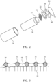
- FIG. 2 is an exploded view of the cartridge 20.
- the cartridge housing 24 that has a size and shape selected to be received into the cavity 18.
- the housing contains capillary material 27, 28 that is soaked in a liquid aerosol-forming substrate.
- the aerosol-forming substrate comprises 39% by weight glycerine, 39% by weight propylene glycol, 20% by weight water and flavourings, and 2% by weight nicotine.
- a capillary material is a material that actively conveys liquid from one end to another, based on relative differences in liquid concentration.
- the capillary material may be made from any suitable material.
- the capillary material is formed from polyester.
- the cartridge housing 24 has an open end to which a heater assembly 30 is fixed.
- the heater assembly 30 comprises a substrate 34 having an aperture 35 formed in it, a pair of electrical contacts 32 fixed to the substrate and separated from each other by a gap 33, and a plurality of electrically conductive heater filaments 36 spanning the aperture and fixed to the electrical contacts on opposite sides of the aperture 35.
- the heater assembly 30 is covered by the releasable seal 26.
- the releasable seal 26 comprises a liquid impermeable plastic sheet that is glued to the heater assembly 30 but which can be easily peeled off.
- a tab is provided on the side of the releasable seal 26 to allow a user to grasp the releasable seal 26 when peeling it off.
- a disc of a first capillary material 27 is provided to contact the heater element 36, 32 in use.
- a larger body of a second capillary material 28 is provided on an opposite side of the first capillary material 27 to the heater assembly. Both the first capillary material and the second capillary material retain liquid aerosol-forming substrate.
- the first capillary material 27, which contacts the heater element, has a higher thermal decomposition temperature (at least 160°C or higher such as approximately 250°C) than the second capillary material 28.
- the first capillary material 27 effectively acts as a spacer separating the heater element 36, 32 from the second capillary material 28 so that the second capillary material is not exposed to temperatures above its thermal decomposition temperature.
- the thermal gradient across the first capillary material is such that the second capillary material is exposed to temperatures below its thermal decomposition temperature.
- the second capillary material 28 may be chosen to have superior wicking performance to the first capillary material 27, may retain more liquid per unit volume than the first capillary material and may be less expensive than the first capillary material.
- the first capillary material is a heat resistant material, such as a fiberglass or fiberglass containing material and the second capillary material is a polymer such as suitable capillary material.
- Exemplary suitable capillary materials include the capillary materials discussed herein and in alternative embodiments may include high density polyethylene (HDPE), or polyethylene terephthalate (PET).
- the capillary material 27, 28 is advantageously oriented in the housing 24 to convey liquid to the heater assembly 30.
- the heater filaments 36 may be in contact with the capillary material 27 and so aerosol-forming substrate can be conveyed directly to the mesh heater.
- Figure 3 is a detailed view of the filaments 36 of the heater assembly 30, showing a meniscus 40 of liquid aerosol-forming substrate between the heater filaments 36. It can be seen that aerosol-forming substrate contacts most of the surface of each filament 36 so that most of the heat generated by the heater assembly 30 passes directly into the aerosol-forming substrate.
- liquid aerosol-forming substrate contacts a large portion of the surface of the heater filaments 36.
- less liquid aerosol-forming substrate will be delivered to the heater filaments 36.
- less energy is taken up by the enthalpy of vaporization and more of the energy supplied to the heater filaments 36 is directed to raising the temperature of the heater filaments.
- the energy required for maintaining a target temperature also decreases as the heater filaments 36 dry out.
- the heater filaments 36 may dry out because the aerosol-forming substrate in the cartridge has been depleted. Alternatively but less likely, the heater filaments 36 may dry out because the user is taking exceptionally long or frequent puffs and the liquid cannot be delivered to the heater filaments 36 as fast as it is being vaporized.
- the heater assembly 30 operates by resistive heating. Current is passed through the filaments 36 under the control of control electronics 16, to heat the filaments to within a desired temperature range.
- the mesh or array of filaments has a significantly higher electrical resistance than the electrical contacts 32 and electrical connectors 19 so that the high temperatures are localised to the filaments. This minimises heat loss to other parts of the aerosol-generating device 10.
- the system is configured to generate heat by providing electrical current to the heater assembly 30 in response to a user puff.
- the system includes a puff sensor configured to detect when a user is drawing air through the mouthpiece portion.
- the puff sensor (not illustrated) is connected to the control electronics 16 and the control electronics 16 are configured to supply current to the heater assembly 30 only when it is determined that the user is puffing on the device.
- Any suitable air flow sensor may be used as a puff sensor, such as a microphone or pressure sensor.
- the electric circuitry 16 is configured to measure the electrical resistance of the heater filaments.
- the heater filaments 36 in this example are formed from stainless steel, and so have a positive temperature coefficient of resistance.
- stainless steel filaments having a relatively high specific heat capacity is ideal.
- the heater filaments 36 may be formed from a material having a negative coefficient of resistance, for which, as the temperature of the heater filaments rises their electrical resistance decreases.
- Figure 4 is plot showing the change in resistance of the heater as detected during a plurality of user puffs. Each of the puffs lasts for a puff duration ⁇ t.
- the x-axis represents time and the y-axis represents detected electrical resistance at the heater assembly 30.
- the change in electrical resistance is detected in three different heating cycles, each corresponding to a user puff: 1) during a heating cycle 500 where the heater filaments 36 are saturated with aerosol-forming substrate, e.g. under normal operation; 2) during a heating cycle 502 where an insufficient supply of aerosol-forming substrate is provided to the heater filaments 36, e.g.
- the electric circuitry may be configured to determine that both heating cycles 502 and 504 include adverse conditions. Alternatively, the electric circuitry may be configured to determine that only heating cycle 504 is an adverse condition.
- the heater assembly 30 has an initial resistance R Ref .
- Said initial resistance R Ref is an intrinsic property of the heater assembly 30. It indicates a reference resistance of the heater assembly 30 at room temperature.
- the initial resistance R Ref of a new cartridge 20 is measured at least once before any heating is applied.
- a detection system is used to determine when a new cartridge 20 is inserted. In some cases R Ref may be measured only once for each cartridge. R Ref may be measured each time the system is switched on.
- the electric circuitry is configured to periodically take updated measurements of R Ref after predetermined time periods in which no power has been supplied to the heater filaments 36. The predetermined time periods each last for 3 minutes, but any suitable time required for the heater filaments 36 to cool from their operating temperature back to the ambient temperature may be chosen. Such periodic updates to R Ref recalibrates the electric circuitry to compensate for changes in ambient temperature, as well as the condition of the heater filaments 36.
- the temperature of the heater filaments 36 rises from the ambient temperature. This causes the electrical resistance R of the heater filaments 36 to rise.
- the parasitic resistance R P is assumed to stay constant. This is because R P is attributable to non-heated components, such as the electrical contacts 32 and electrical connectors 19.
- the value of R P is assumed to be the same for all cartridges and will not be affected by changing over to a different cartridge.
- the parasitic resistance R P value, for a particular aerosol-generating device 20, is stored in the memory of the electric circuitry.
- FIG. 4 illustrates the change in electrical resistance ⁇ R across a heater assembly 30 as it is being heated up from an ambient temperature to, and subsequently as it is being maintained at a target heater temperature during user puffs.
- Each of the heating cycles 500, 502, 504 corresponds to a user puff and has a duration of ⁇ t.
- each heating cycle begins with a heating assembly 30 at ambient temperature and the resistance of the heating assembly, R Ref .
- R Ref the resistance of the heating assembly
- the electrical resistance R in actual use, may start at a level that is higher than R Ref .
- the temperature, or the corresponding electrical resistance R, of the heater assembly 30 at the beginning of the heating cycle is not significant. This is because the electric circuitry is configured to determine an adverse condition once the heater assembly 30 has reached its target temperature.
- the heater assembly 30 in heating cycle 500 is saturated with liquid aerosol-forming substrate. This is representative of a normal operating condition.
- the temperature of the heating assembly 30 is configured to be regulated by a factor K of 1.2.
- the electric circuitry supplies electrical energy to the heater assembly 30 whilst measuring the heater resistance R. This period of heating may be referred to as a heating-up phase.
- the electric circuitry may continue supplying power to the heater assembly 30 until the measured heater resistance R equals to R T , which in this case is 1.2 R 0 .
- the electric circuitry may continue to supply power, either at a reduced level or in an intermittent manner, to regulate the heater resistance R at the target heater resistance R T . This results in a constant heater temperature.
- This period of temperature maintenance may be referred to as a maintenance phase. During such maintenance phase, the heater resistance R is regulated to remain at a constant value.
- the factor K may be factory set as a default value.
- the factor K correlates to a default target temperature of the heater filaments 36.
- a user may adjust the factor K from its default value using an user input device, for example a set of mechanical buttons or a scroll wheel. This allows the users to adjust the target heater temperature according to their own preference.
- the rate of temperature rise, dT/dt, at the heater filaments 36 increases during the heating up phase. Accordingly, the rate of increase in resistance, dR/dt, at the heater filaments 36 during this period also increases. Such situation may arise for example, when the liquid substrate cannot be fully replenished at the heater filaments 36.
- This is illustrated in heating cycle 502 of Figure 4 .
- the heater filaments 36 have an insufficient liquid substrate supply.
- the rate of increase in electrical resistance dR/dt is steeper than that during the heating cycle 500.
- the rate of increase in electrical resistance dR/dt rises even further when the heater filaments 36 are completely depleted of liquid substrate, as shown in the heating cycle 504 of Figure 4 .
- the heater temperature rises so rapidly that the heater assembly 30 cannot dissipate the heat fast enough, causing the electrical resistance to rise above R T . This can be seen in heating cycle 504.
- the electric circuitry is configured to cease power supply to the heater assembly upon detecting the rate of increase in electrical resistance dR/dt exceeds an upper threshold.
- an upper threshold may be a rate of increase in electrical resistance that is only exhibited when the cartridge is empty.
- a visual warning such as a flashing LED signal, may be given to the user to prompt a cartridge replacement.
- the power supply to the heater assembly 30 may also be used for determining the depletion of aerosol-forming substrate at the heater filaments 36. This is illustrated by heating cycles 510, 512 and 514 shown in Figure 5 , each showing a power supplied during heating cycles 500, 502 and 504 in Figure 4 .
- the power supplied is determined based on a change in power, ⁇ W, within a specific time interval. For example, the power supplied is detected every 100ms.
- Heating cycle 510 shows the change in power supplied during a puff where the heater filament 36 is saturated with liquid substrate. It can be seen that the power supply gradually rises to its highest level during the heating up period. This allows the heater assembly 30 heat up quickly. In some cases the power supply may start at its highest level at the beginning of the heating cycle, which allows even faster heating.
- the power supply then reduces and stabilises at a lower level during the maintenance phase.
- the electric circuitry sets a predetermined power supply limit 516 for limiting the maximum power supply to the heater assembly 30.
- the power supply limit 516 forms a passive safety mechanism to prevent overheating.
- the power supply limit 516 is variable, with a high limit during the heating up phase compared to the maintenance phase respectively.
- Heating cycle 512 shows the change in power supply during a puff where insufficient liquid substrate is being supplied to the heater filament.
- the power supply during the heating up phase in heating cycle 512 is similar to the power supplied when the heater filaments 36 saturated with liquid substrate as shown in heating cycle 510.
- the power required for maintaining the heater assembly 30 at its target temperature gradually reduces towards the end of the user puff.
- Heating cycle 514 shows the change in power supply during a puff where liquid substrate is depleted at the heater filament. Due to a lack of liquid substrate, the power as supplied to heater assembly 30 during the heating up phase is significantly lower than that in heating cycles 510 and 512. Similar to heating cycle 512, as the liquid substrate is depleted at the heater filaments 36, the power required for maintaining its target temperature reduces rapidly towards the end of the user puff.
- the electric circuitry is configured to detect insufficient liquid substrate at the heater filaments 36 during the maintenance phase based on a reduction in the power supplied. More specifically, once the heater assembly 30 has reached the target resistance representative of the target temperature, the power supply gradually reduces until it reaches a predetermined minimum power threshold, P min . The electric circuitry then determines an insufficient liquid substrate level at the heater filaments 36, as shown in heating cycle 512, or as shown in heating cycle 514 when the cartridge is empty.
- heater filaments that are saturated with liquid substrate require more power than the minimum power threshold, P min to maintain its electrical resistance R at the target resistance R T .
- P min a power consumption beneath the predetermined minimum power threshold, P min , can only be achieved if there is a lack of liquid substrate at the heater filaments 36.
- the electric circuitry is configured to cease power supply immediately if it detects the power supply has dropped below the minimum power threshold, P min .
- the electric circuitry upon detecting insufficient liquid substrate at the heater filaments 36, the electric circuitry does not cease power supply immediately. Instead, the electric circuitry may continue power supply for one or more further puffs. For example, the electric circuitry may continue power supply for two further puffs. This allows the electric circuitry to continue monitoring power supply in successive puffs, to confirm substrate depletion at the heater filaments 36.
- the depletion of liquid substrate may be determined by monitoring the reduction in a minimum power supply over successive puffs. More specifically, the electric circuitry may compare the minimum power supply P min as recorded in each of the successive puffs. The electric circuitry may then determine an adverse condition when the difference between the minimum power supply P min over successive cycles exceeds an offset threshold ⁇ P offset .
- FIG. 6 shows the power supply over three successive heating cycles corresponding to three successive user puffs: 1) during a heating cycle 520 in which the heater filaments are saturated with aerosol-forming substrate, which are normal operating conditions; 2) during a heating cycle 522 in which an insufficient supply of aerosol-forming substrate is provided to the heater filaments; and 3) during a heating cycle 524 in which the heater filaments are depleted of aerosol-forming substrate.
- the minimum power supply during a puff is P min1 . If all of the successive puffs within a particular session take place under normal operation, the minimum power supply P min recorded during each of the heating cycles will be approximately P min1 . That is, under normal operating condition the recorded minimum power supply P min from puff to puff is substantially consistent.
- the offset in the minimum power supply P min is expected to be very small. In particular, when the heater filaments 36 are saturated with liquid substrate the offset in minimum power supply will not exceed a predetermined threshold ⁇ P offset .
- the quantity of available liquid aerosol-forming substrate in the cartridge reduces with each successive puffs.
- the minimum power supply P min recorded during a puff reduces with each successive puffs.
- P min2 represents the minimum power supply recorded during a second heating cycle 522, which is lower than P min1 as recorded during a preceding heating cycle.
- the difference between P min2 and P min1 exceeds the predetermined ⁇ P offset threshold, so P min2 ⁇ (P mim1 - ⁇ P offset ).
- the electric circuitry therefore determines that there is an insufficient supply of liquid substrate at the heater assembly. As a result, the electric circuitry immediately ceases power supply to the heater filaments 36 and indicates to the user to replace the empty cartridge.
- the electric circuitry may continue to monitor minimum power supply for at least one or more heating cycle.
- P min3 is recorded during a third heating cycle 524 succeeding the second heating cycle 522.
- the difference between P min3 and P min2 again exceeds the predetermined ⁇ P offset threshold, so P min3 ⁇ (P min2 - ⁇ P offset ).
- the electric circuitry determines that the liquid substrate is depleted at the heater filaments 36. As a result, the electric circuitry ceases power supply to the heater assembly 30 and indicates to the user to replace the empty cartridge.
- the electric circuitry may be configured to compare a recorded minimum power supply P min with one that has been recorded during the first heating cycle 520, so P min1.
- the electric circuitry is configured to compare P min3 with P min1 . If the difference between P min3 and P min1 exceeds the predetermined ⁇ P offset threshold, so that P min3 ⁇ (P min1 - ⁇ P offset ), the electric circuitry determines that the liquid substrate is depleted at the heater filaments 36. This ensures that comparison is always made against a cartridge that is new, or at least not depleted of liquid aerosol.
- the electric circuitry may compare the minimum power supplied with a rolling average of minimum power supplied P minAV over n preceding heating cycles, where n is a positive integer greater than 1. For example, the electric circuitry is configure to average the P min as recorded in the last n puffs to produce said rolling average P minA v. If the difference between P min and P minAV exceeds the predetermined ⁇ P offset threshold, so that P min ⁇ (P minAV - ⁇ P offset ), the electric circuitry determines that the liquid substrate is depleted at the heater filaments 36. This ensures that comparison is less likely to be affected by fluctuations in the ambient conditions.
- a reduction in the minimum power supplied during the maintenance phase is a good indicator of insufficient liquid substrate at the heater filaments 36.
- the electric circuitry cannot ascertain an adverse condition until the power supply has reduced below the minimum power threshold. That is, a response to said adverse condition may not be promptly issued.
- the electric circuitry is configured to determine insufficient liquid substrate from the first derivative of power supply with respect to time, dP/dt.
- FIG. 7 shows the rate of change in power supply during three heating cycles corresponding to user puffs: 1) during a heating cycle 530 in which the heater filaments 36 are saturated with aerosol-forming substrate, which are normal operating conditions; 2) during a heating cycle 532 in which an insufficient supply of aerosol-forming substrate is provided to the heater filaments 36; and 3) during a heating cycle 534 in which the heater filaments are depleted of aerosol-forming substrate.
- dP/dt gradually reduces as the heater assembly 30 heats up. Once the electrical resistance reaches the target resistance R T and is being maintained, dP/dt stays at a more or less constant level. This is because the amount of substrate vaporisation is maintained constant at the target temperature.
- dP/dt reduces in order to maintain the electrical resistance at the target resistance R T .
- the electric circuitry is configured to determine an adverse condition when dP/dt reduces below a predetermined minimum rate of change threshold, dP/dt min .
- dP/dt min a predetermined minimum rate of change threshold
- dP/dt min a sudden loss of liquid substrate supply at the heater filaments 36 would cause the power supply to reduce rapidly. This results in a decreasing dP/dt.
- dP/dt is reduced below the predetermined minimum rate of change threshold, dP/dt min .
- the methods as described in the various embodiments may each be applied to determine an adverse condition.
- said determination of an adverse condition may be based on a combination of a plurality of the methods described.
- An aerosol-generating system may be configured to use different methods of determining an adverse condition in different modes.
- the described methods may also be used in an internal system diagnostic tool.
Claims (7)
- Système de génération d'aérosol à fonctionnement électrique comprenant :un élément de chauffage (36) destiné à chauffer un substrat formant aérosol ;une alimentation électrique (14) destinée à alimenter en électricité l'élément de chauffage (36) ;un capteur de température destiné à capter une température au niveau de l'élément de chauffage ; etune circuiterie électrique (16) en communication avec l'élément de chauffage (36), le capteur et et l'alimentation électrique (14), la circuiterie électrique (16) comprenant une mémoire et étant configurée pour :réguler l'alimentation électrique de l'élément de chauffage (36) sur la base de la température mesurée à partir du capteur de température ;déterminer une condition indésirable lorsqu'une réduction d'alimentation électrique fournie à l'élément de chauffage (36) requise pour atteindre ou maintenir une température prédéterminée sur des cycles de chauffage successifs tombe à l'extérieur d'une plage prédéfinie, par comparaison de l'alimentation électrique minimale fournie à l'élément de chauffage (36) dans un cycle de chauffage donné avec celle fournie dans un ou plusieurs cycles de chauffage précédents, ladite plage prédéfinie étant stockée dans la mémoire ; etcommander l'alimentation électrique fournie à l'élément de chauffage (36) sur la base du fait qu'il existe ou non une condition indésirable ou de fournir une indication quand il existe une condition indésirable ;dans lequel le système comprend un dispositif (10) et une cartouche (20) amovible, dans lequel l'alimentation électrique (14) et la circuiterie électrique (16) sont dans le dispositif (10) et l'élément de chauffage électrique (36) est dans la cartouche (20) amovible, et dans lequel la cartouche (20) comprend un substrat formant aérosol liquide.
- Système de génération d'aérosol à fonctionnement électrique selon la revendication 1, dans lequel la circuiterie électrique (16) est configurée pour déterminer une condition indésirable seulement après l'élévation de la température au niveau de l'élément de chauffage (36) d'une température initiale à une température cible.
- Système de génération d'aérosol à fonctionnement électrique selon les revendications 1 ou 2, dans lequel la plage prédéfinie est basée sur une valeur seuil maximal d'un taux de variation de l'alimentation électrique fournie ou une valeur seuil minimale de réduction de l'alimentation électrique fournie sur des cycles de chauffage successifs.
- Système de génération d'aérosol à fonctionnement électrique selon l'une quelconque des revendications précédentes, dans lequel le capteur de température est configuré pour mesurer une résistance électrique de l'élément de chauffage (36).
- Système de génération d'aérosol à fonctionnement électrique selon l'une quelconque des revendications précédentes, comprenant en outre un détecteur de bouffée destiné à détecter le moment auquel un utilisateur prend une bouffée sur le système, dans lequel le détecteur de bouffée est en communication avec la circuiterie électrique et dans lequel la circuiterie électrique (16) est configurée pour fournir une alimentation électrique de l'alimentation électrique (14) à l'élément de chauffage (36) lorsqu'une bouffée est détectée par le détecteur de bouffée pour que chaque bouffée corresponde à un cycle de chauffage, et dans lequel la circuiterie électrique (16) est configurée pour déterminer s'il existe une condition indésirable pendant chaque cycle de chauffage.
- Procédé de commande de l'alimentation électrique d'un élément de chauffage (36) dans un système de génération d'aérosol à fonctionnement électrique, comprenant :la mesure d'une température au niveau d'un élément de chauffage (36) ;la régulation de l'alimentation électrique de l'élément de chauffage (36) sur la base de la température mesurée ;la détermination d'une condition indésirable lorsqu'une réduction d'alimentation électrique requise pour atteindre ou maintenir une température prédéterminée sur des cycles de chauffage successifs tombe à l'extérieur d'une plage prédéfinie, par comparaison de l'alimentation électrique minimale fournie à l'élément de chauffage (36) dans un cycle de chauffage donné avec celle fournie dans un ou plusieurs cycles de chauffage précédents, ladite plage prédéfinie étant stockée dans la mémoire ; etla commande de l'alimentation électrique fournie à l'élément de chauffage (36) sur la base du fait qu'il existe une condition indésirable ou la fourniture d'une indication lorsqu'il existe une condition indésirable.
- Produit de programme informatique directement chargeable dans la mémoire interne d'un microprocesseur comprenant des portions de code logiciel pour la réalisation des étapes de la revendication 6 lorsque ledit produit s'exécute sur un microprocesseur dans un système de génération d'aérosol à fonctionnement électrique, le système comprenant un élément de chauffage (36) destiné à chauffer un substrat formant aérosol, un capteur destiné à capter une température de l'élément de chauffage et une alimentation électrique (14) destinée à fournir une alimentation électrique au dispositif de chauffage (36), le microprocesseur étant raccordé au dispositif de chauffage électrique (36), au capteur et à l'alimentation électrique (14).
Priority Applications (1)
| Application Number | Priority Date | Filing Date | Title |
|---|---|---|---|
| EP23188511.2A EP4268642A3 (fr) | 2018-05-30 | 2019-05-22 | Détection de conditions de chauffage défavorables dans un système de génération d'aérosol chauffé électriquement |
Applications Claiming Priority (2)
| Application Number | Priority Date | Filing Date | Title |
|---|---|---|---|
| EP18175207 | 2018-05-30 | ||
| PCT/EP2019/063266 WO2019228894A1 (fr) | 2018-05-30 | 2019-05-22 | Détection de conditions de chauffage défavorables dans un système de génération d'aérosol chauffé électriquement |
Related Child Applications (2)
| Application Number | Title | Priority Date | Filing Date |
|---|---|---|---|
| EP23188511.2A Division EP4268642A3 (fr) | 2018-05-30 | 2019-05-22 | Détection de conditions de chauffage défavorables dans un système de génération d'aérosol chauffé électriquement |
| EP23188511.2A Division-Into EP4268642A3 (fr) | 2018-05-30 | 2019-05-22 | Détection de conditions de chauffage défavorables dans un système de génération d'aérosol chauffé électriquement |
Publications (3)
| Publication Number | Publication Date |
|---|---|
| EP3801080A1 EP3801080A1 (fr) | 2021-04-14 |
| EP3801080B1 true EP3801080B1 (fr) | 2023-09-06 |
| EP3801080C0 EP3801080C0 (fr) | 2023-09-06 |
Family
ID=62492518
Family Applications (2)
| Application Number | Title | Priority Date | Filing Date |
|---|---|---|---|
| EP19725729.8A Active EP3801080B1 (fr) | 2018-05-30 | 2019-05-22 | Détection de conditions de chauffage défavorables dans un système de génération d'aérosol chauffé électriquement |
| EP23188511.2A Pending EP4268642A3 (fr) | 2018-05-30 | 2019-05-22 | Détection de conditions de chauffage défavorables dans un système de génération d'aérosol chauffé électriquement |
Family Applications After (1)
| Application Number | Title | Priority Date | Filing Date |
|---|---|---|---|
| EP23188511.2A Pending EP4268642A3 (fr) | 2018-05-30 | 2019-05-22 | Détection de conditions de chauffage défavorables dans un système de génération d'aérosol chauffé électriquement |
Country Status (9)
| Country | Link |
|---|---|
| US (1) | US20210204609A1 (fr) |
| EP (2) | EP3801080B1 (fr) |
| JP (2) | JP7382347B2 (fr) |
| KR (1) | KR20210014640A (fr) |
| CN (1) | CN112087962A (fr) |
| BR (1) | BR112020022094A2 (fr) |
| PH (1) | PH12020551947A1 (fr) |
| PL (1) | PL3801080T3 (fr) |
| WO (1) | WO2019228894A1 (fr) |
Families Citing this family (8)
| Publication number | Priority date | Publication date | Assignee | Title |
|---|---|---|---|---|
| US11730199B2 (en) | 2018-06-07 | 2023-08-22 | Juul Labs, Inc. | Cartridges for vaporizer devices |
| CA3118504A1 (fr) * | 2018-11-08 | 2020-05-14 | Juul Labs, Inc. | Dispositif vaporisateur comprenant plus d'un element chauffant |
| WO2021191156A1 (fr) * | 2020-03-23 | 2021-09-30 | Philip Morris Products S.A. | Cartouche avec circuit résonant pour dispositif de génération d'aérosol |
| CN116138503A (zh) * | 2021-11-19 | 2023-05-23 | 深圳市合元科技有限公司 | 气雾生成装置及控制方法 |
| CN113966872A (zh) * | 2021-11-22 | 2022-01-25 | 深圳市石开科技有限公司 | 一种雾化芯及其制造方法、以及雾化器 |
| WO2023214733A1 (fr) * | 2022-05-02 | 2023-11-09 | Kt&G Corporation | Dispositif de génération d'aérosol |
| WO2023214734A1 (fr) * | 2022-05-04 | 2023-11-09 | Kt&G Corporation | Dispositif de génération d'aérosol |
| WO2023224310A1 (fr) * | 2022-05-17 | 2023-11-23 | Kt&G Corporation | Dispositif de génération d'aérosol |
Family Cites Families (12)
| Publication number | Priority date | Publication date | Assignee | Title |
|---|---|---|---|---|
| EP2468117A1 (fr) | 2010-12-24 | 2012-06-27 | Philip Morris Products S.A. | Système de génération d'aérosol disposant de supports pour déterminer la déplétion d'un substrat liquide |
| EP2609820A1 (fr) * | 2011-12-30 | 2013-07-03 | Philip Morris Products S.A. | Détection d'un substrat formant un aérosol dans un dispositif de génération d'aérosol |
| MY177353A (en) * | 2011-12-30 | 2020-09-14 | Philip Morris Products Sa | Aerosol-generating system with consumption monitoring and feedback |
| LT3002657T (lt) * | 2012-09-11 | 2017-04-25 | Philip Morris Products S.A. | Įrenginys ir būdas elektriniam šildytuvui, ribojančiam temperatūrą, kontroliuoti |
| US9974334B2 (en) * | 2014-01-17 | 2018-05-22 | Rai Strategic Holdings, Inc. | Electronic smoking article with improved storage of aerosol precursor compositions |
| KR102502317B1 (ko) | 2014-04-30 | 2023-02-23 | 필립모리스 프로덕츠 에스.에이. | 배터리 표시가 있는 에어로졸 발생 장치 |
| GB2529629B (en) | 2014-08-26 | 2021-05-12 | Nicoventures Trading Ltd | Electronic aerosol provision system |
| WO2016050922A1 (fr) | 2014-10-03 | 2016-04-07 | Novo Nordisk A/S | Procédé de formation d'aiguilles d'injection |
| KR20160080314A (ko) | 2014-12-26 | 2016-07-08 | 주식회사 포스코 | 페라이트계 스테인리스강 및 그 제조방법 |
| CA3184421A1 (fr) | 2015-03-26 | 2016-09-29 | Philip Morris Products S.A. | Gestion de dispositif de chauffage |
| CN109475191B (zh) | 2016-07-25 | 2022-07-22 | 菲利普莫里斯生产公司 | 加热器管理 |
| CA3033086A1 (fr) | 2016-08-05 | 2018-02-08 | Juul Labs, Inc. | Commande assistee par anemometrie d'un vaporisateur |
-
2019
- 2019-05-22 WO PCT/EP2019/063266 patent/WO2019228894A1/fr active Search and Examination
- 2019-05-22 EP EP19725729.8A patent/EP3801080B1/fr active Active
- 2019-05-22 KR KR1020207034284A patent/KR20210014640A/ko active Search and Examination
- 2019-05-22 JP JP2020562176A patent/JP7382347B2/ja active Active
- 2019-05-22 EP EP23188511.2A patent/EP4268642A3/fr active Pending
- 2019-05-22 CN CN201980030658.8A patent/CN112087962A/zh active Pending
- 2019-05-22 PL PL19725729.8T patent/PL3801080T3/pl unknown
- 2019-05-22 BR BR112020022094-9A patent/BR112020022094A2/pt unknown
- 2019-05-22 US US17/057,901 patent/US20210204609A1/en active Pending
-
2020
- 2020-11-11 PH PH12020551947A patent/PH12020551947A1/en unknown
-
2023
- 2023-11-06 JP JP2023189280A patent/JP2024001365A/ja active Pending
Also Published As
| Publication number | Publication date |
|---|---|
| EP4268642A3 (fr) | 2023-12-27 |
| WO2019228894A1 (fr) | 2019-12-05 |
| EP3801080A1 (fr) | 2021-04-14 |
| EP3801080C0 (fr) | 2023-09-06 |
| JP2021526359A (ja) | 2021-10-07 |
| EP4268642A2 (fr) | 2023-11-01 |
| KR20210014640A (ko) | 2021-02-09 |
| US20210204609A1 (en) | 2021-07-08 |
| PL3801080T3 (pl) | 2024-03-18 |
| JP7382347B2 (ja) | 2023-11-16 |
| BR112020022094A2 (pt) | 2021-02-02 |
| JP2024001365A (ja) | 2024-01-09 |
| CN112087962A (zh) | 2020-12-15 |
| PH12020551947A1 (en) | 2021-08-16 |
Similar Documents
| Publication | Publication Date | Title |
|---|---|---|
| US20210212170A1 (en) | Heater management | |
| EP3801080B1 (fr) | Détection de conditions de chauffage défavorables dans un système de génération d'aérosol chauffé électriquement | |
| EP3801084B1 (fr) | Procédés de détection de conditions de chauffage dans un système de génération d'aérosol | |
| EP3487326B1 (fr) | Gestion de chauffage | |
| US20200367569A1 (en) | Aerosol-generating device and method for controlling a heater of an aerosol-generating device | |
| RU2795873C2 (ru) | Электрическая система, генерирующай аэрозоль, способ управления подачей питания на нагревательный элемент в электрической системе и внутреннее запоминающее устройство микропроцессора | |
| RU2792959C2 (ru) | Электрическая генерирующая аэрозоль система и способ управления подачей мощности на нагревательный элемент в электрической генерирующей аэрозоль системе |
Legal Events
| Date | Code | Title | Description |
|---|---|---|---|
| STAA | Information on the status of an ep patent application or granted ep patent |
Free format text: STATUS: UNKNOWN |
|
| STAA | Information on the status of an ep patent application or granted ep patent |
Free format text: STATUS: THE INTERNATIONAL PUBLICATION HAS BEEN MADE |
|
| STAA | Information on the status of an ep patent application or granted ep patent |
Free format text: STATUS: THE INTERNATIONAL PUBLICATION HAS BEEN MADE |
|
| PUAI | Public reference made under article 153(3) epc to a published international application that has entered the european phase |
Free format text: ORIGINAL CODE: 0009012 |
|
| STAA | Information on the status of an ep patent application or granted ep patent |
Free format text: STATUS: REQUEST FOR EXAMINATION WAS MADE |
|
| 17P | Request for examination filed |
Effective date: 20201202 |
|
| AK | Designated contracting states |
Kind code of ref document: A1 Designated state(s): AL AT BE BG CH CY CZ DE DK EE ES FI FR GB GR HR HU IE IS IT LI LT LU LV MC MK MT NL NO PL PT RO RS SE SI SK SM TR |
|
| AX | Request for extension of the european patent |
Extension state: BA ME |
|
| DAV | Request for validation of the european patent (deleted) | ||
| DAX | Request for extension of the european patent (deleted) | ||
| REG | Reference to a national code |
Ref country code: DE Ref legal event code: R079 Ref document number: 602019036767 Country of ref document: DE Free format text: PREVIOUS MAIN CLASS: A24F0047000000 Ipc: A24F0040530000 Ref country code: DE Ref legal event code: R079 |
|
| GRAP | Despatch of communication of intention to grant a patent |
Free format text: ORIGINAL CODE: EPIDOSNIGR1 |
|
| RIC1 | Information provided on ipc code assigned before grant |
Ipc: A24F 40/10 20200101ALN20230209BHEP Ipc: A24F 40/57 20200101ALI20230209BHEP Ipc: A24F 40/53 20200101AFI20230209BHEP |
|
| STAA | Information on the status of an ep patent application or granted ep patent |
Free format text: STATUS: GRANT OF PATENT IS INTENDED |
|
| INTG | Intention to grant announced |
Effective date: 20230316 |
|
| P01 | Opt-out of the competence of the unified patent court (upc) registered |
Effective date: 20230529 |
|
| GRAS | Grant fee paid |
Free format text: ORIGINAL CODE: EPIDOSNIGR3 |
|
| GRAA | (expected) grant |
Free format text: ORIGINAL CODE: 0009210 |
|
| STAA | Information on the status of an ep patent application or granted ep patent |
Free format text: STATUS: THE PATENT HAS BEEN GRANTED |
|
| AK | Designated contracting states |
Kind code of ref document: B1 Designated state(s): AL AT BE BG CH CY CZ DE DK EE ES FI FR GB GR HR HU IE IS IT LI LT LU LV MC MK MT NL NO PL PT RO RS SE SI SK SM TR |
|
| REG | Reference to a national code |
Ref country code: GB Ref legal event code: FG4D |
|
| REG | Reference to a national code |
Ref country code: CH Ref legal event code: EP |
|
| REG | Reference to a national code |
Ref country code: IE Ref legal event code: FG4D |
|
| REG | Reference to a national code |
Ref country code: DE Ref legal event code: R096 Ref document number: 602019036767 Country of ref document: DE |
|
| REG | Reference to a national code |
Ref country code: RO Ref legal event code: EPE |
|
| U01 | Request for unitary effect filed |
Effective date: 20230906 |
|
| U07 | Unitary effect registered |
Designated state(s): AT BE BG DE DK EE FI FR IT LT LU LV MT NL PT SE SI Effective date: 20230912 |
|
| P04 | Withdrawal of opt-out of the competence of the unified patent court (upc) registered |
Effective date: 20230908 |
|
| PG25 | Lapsed in a contracting state [announced via postgrant information from national office to epo] |
Ref country code: GR Free format text: LAPSE BECAUSE OF FAILURE TO SUBMIT A TRANSLATION OF THE DESCRIPTION OR TO PAY THE FEE WITHIN THE PRESCRIBED TIME-LIMIT Effective date: 20231207 |
|
| PG25 | Lapsed in a contracting state [announced via postgrant information from national office to epo] |
Ref country code: RS Free format text: LAPSE BECAUSE OF FAILURE TO SUBMIT A TRANSLATION OF THE DESCRIPTION OR TO PAY THE FEE WITHIN THE PRESCRIBED TIME-LIMIT Effective date: 20230906 Ref country code: NO Free format text: LAPSE BECAUSE OF FAILURE TO SUBMIT A TRANSLATION OF THE DESCRIPTION OR TO PAY THE FEE WITHIN THE PRESCRIBED TIME-LIMIT Effective date: 20231206 Ref country code: HR Free format text: LAPSE BECAUSE OF FAILURE TO SUBMIT A TRANSLATION OF THE DESCRIPTION OR TO PAY THE FEE WITHIN THE PRESCRIBED TIME-LIMIT Effective date: 20230906 Ref country code: GR Free format text: LAPSE BECAUSE OF FAILURE TO SUBMIT A TRANSLATION OF THE DESCRIPTION OR TO PAY THE FEE WITHIN THE PRESCRIBED TIME-LIMIT Effective date: 20231207 |
|
| PG25 | Lapsed in a contracting state [announced via postgrant information from national office to epo] |
Ref country code: IS Free format text: LAPSE BECAUSE OF FAILURE TO SUBMIT A TRANSLATION OF THE DESCRIPTION OR TO PAY THE FEE WITHIN THE PRESCRIBED TIME-LIMIT Effective date: 20240106 |