EP3800553A1 - Information processing system, information processing method, and information processing program - Google Patents
Information processing system, information processing method, and information processing program Download PDFInfo
- Publication number
- EP3800553A1 EP3800553A1 EP20198649.4A EP20198649A EP3800553A1 EP 3800553 A1 EP3800553 A1 EP 3800553A1 EP 20198649 A EP20198649 A EP 20198649A EP 3800553 A1 EP3800553 A1 EP 3800553A1
- Authority
- EP
- European Patent Office
- Prior art keywords
- arithmetic device
- data
- task
- configuration
- arithmetic
- Prior art date
- Legal status (The legal status is an assumption and is not a legal conclusion. Google has not performed a legal analysis and makes no representation as to the accuracy of the status listed.)
- Granted
Links
- 230000010365 information processing Effects 0.000 title claims abstract description 71
- 238000003672 processing method Methods 0.000 title claims description 12
- 230000004044 response Effects 0.000 claims abstract description 20
- 238000012545 processing Methods 0.000 claims description 554
- 230000008859 change Effects 0.000 claims description 166
- 238000000034 method Methods 0.000 claims description 139
- 230000008569 process Effects 0.000 claims description 80
- 238000012546 transfer Methods 0.000 claims description 9
- 230000004888 barrier function Effects 0.000 description 123
- 239000003550 marker Substances 0.000 description 106
- 238000010586 diagram Methods 0.000 description 57
- 230000005540 biological transmission Effects 0.000 description 50
- 238000011144 upstream manufacturing Methods 0.000 description 18
- 238000005259 measurement Methods 0.000 description 12
- 230000002159 abnormal effect Effects 0.000 description 10
- 238000001514 detection method Methods 0.000 description 10
- 238000013480 data collection Methods 0.000 description 7
- 230000006870 function Effects 0.000 description 6
- 238000012544 monitoring process Methods 0.000 description 4
- 238000004891 communication Methods 0.000 description 3
- 230000005856 abnormality Effects 0.000 description 2
- 206010039203 Road traffic accident Diseases 0.000 description 1
- 230000010485 coping Effects 0.000 description 1
- 230000003111 delayed effect Effects 0.000 description 1
- 230000009365 direct transmission Effects 0.000 description 1
- 238000005516 engineering process Methods 0.000 description 1
- 230000006872 improvement Effects 0.000 description 1
- 239000004065 semiconductor Substances 0.000 description 1
- 239000007787 solid Substances 0.000 description 1
- XLYOFNOQVPJJNP-UHFFFAOYSA-N water Substances O XLYOFNOQVPJJNP-UHFFFAOYSA-N 0.000 description 1
Images


Classifications
-
- G—PHYSICS
- G06—COMPUTING; CALCULATING OR COUNTING
- G06F—ELECTRIC DIGITAL DATA PROCESSING
- G06F11/00—Error detection; Error correction; Monitoring
- G06F11/07—Responding to the occurrence of a fault, e.g. fault tolerance
- G06F11/14—Error detection or correction of the data by redundancy in operation
- G06F11/1402—Saving, restoring, recovering or retrying
- G06F11/1415—Saving, restoring, recovering or retrying at system level
- G06F11/1438—Restarting or rejuvenating
-
- G—PHYSICS
- G06—COMPUTING; CALCULATING OR COUNTING
- G06F—ELECTRIC DIGITAL DATA PROCESSING
- G06F15/00—Digital computers in general; Data processing equipment in general
- G06F15/76—Architectures of general purpose stored program computers
- G06F15/78—Architectures of general purpose stored program computers comprising a single central processing unit
- G06F15/7867—Architectures of general purpose stored program computers comprising a single central processing unit with reconfigurable architecture
- G06F15/7871—Reconfiguration support, e.g. configuration loading, configuration switching, or hardware OS
- G06F15/7882—Reconfiguration support, e.g. configuration loading, configuration switching, or hardware OS for self reconfiguration
-
- G—PHYSICS
- G06—COMPUTING; CALCULATING OR COUNTING
- G06F—ELECTRIC DIGITAL DATA PROCESSING
- G06F3/00—Input arrangements for transferring data to be processed into a form capable of being handled by the computer; Output arrangements for transferring data from processing unit to output unit, e.g. interface arrangements
- G06F3/06—Digital input from, or digital output to, record carriers, e.g. RAID, emulated record carriers or networked record carriers
- G06F3/0601—Interfaces specially adapted for storage systems
- G06F3/0602—Interfaces specially adapted for storage systems specifically adapted to achieve a particular effect
- G06F3/0614—Improving the reliability of storage systems
- G06F3/0619—Improving the reliability of storage systems in relation to data integrity, e.g. data losses, bit errors
-
- G—PHYSICS
- G06—COMPUTING; CALCULATING OR COUNTING
- G06F—ELECTRIC DIGITAL DATA PROCESSING
- G06F3/00—Input arrangements for transferring data to be processed into a form capable of being handled by the computer; Output arrangements for transferring data from processing unit to output unit, e.g. interface arrangements
- G06F3/06—Digital input from, or digital output to, record carriers, e.g. RAID, emulated record carriers or networked record carriers
- G06F3/0601—Interfaces specially adapted for storage systems
- G06F3/0628—Interfaces specially adapted for storage systems making use of a particular technique
- G06F3/0646—Horizontal data movement in storage systems, i.e. moving data in between storage devices or systems
- G06F3/065—Replication mechanisms
-
- G—PHYSICS
- G06—COMPUTING; CALCULATING OR COUNTING
- G06F—ELECTRIC DIGITAL DATA PROCESSING
- G06F3/00—Input arrangements for transferring data to be processed into a form capable of being handled by the computer; Output arrangements for transferring data from processing unit to output unit, e.g. interface arrangements
- G06F3/06—Digital input from, or digital output to, record carriers, e.g. RAID, emulated record carriers or networked record carriers
- G06F3/0601—Interfaces specially adapted for storage systems
- G06F3/0668—Interfaces specially adapted for storage systems adopting a particular infrastructure
- G06F3/0671—In-line storage system
- G06F3/0673—Single storage device
-
- G—PHYSICS
- G06—COMPUTING; CALCULATING OR COUNTING
- G06F—ELECTRIC DIGITAL DATA PROCESSING
- G06F9/00—Arrangements for program control, e.g. control units
- G06F9/06—Arrangements for program control, e.g. control units using stored programs, i.e. using an internal store of processing equipment to receive or retain programs
- G06F9/46—Multiprogramming arrangements
- G06F9/461—Saving or restoring of program or task context
-
- G—PHYSICS
- G06—COMPUTING; CALCULATING OR COUNTING
- G06F—ELECTRIC DIGITAL DATA PROCESSING
- G06F11/00—Error detection; Error correction; Monitoring
- G06F11/30—Monitoring
- G06F11/34—Recording or statistical evaluation of computer activity, e.g. of down time, of input/output operation ; Recording or statistical evaluation of user activity, e.g. usability assessment
- G06F11/3404—Recording or statistical evaluation of computer activity, e.g. of down time, of input/output operation ; Recording or statistical evaluation of user activity, e.g. usability assessment for parallel or distributed programming
-
- G—PHYSICS
- G06—COMPUTING; CALCULATING OR COUNTING
- G06F—ELECTRIC DIGITAL DATA PROCESSING
- G06F11/00—Error detection; Error correction; Monitoring
- G06F11/30—Monitoring
- G06F11/34—Recording or statistical evaluation of computer activity, e.g. of down time, of input/output operation ; Recording or statistical evaluation of user activity, e.g. usability assessment
- G06F11/3409—Recording or statistical evaluation of computer activity, e.g. of down time, of input/output operation ; Recording or statistical evaluation of user activity, e.g. usability assessment for performance assessment
- G06F11/3419—Recording or statistical evaluation of computer activity, e.g. of down time, of input/output operation ; Recording or statistical evaluation of user activity, e.g. usability assessment for performance assessment by assessing time
- G06F11/3423—Recording or statistical evaluation of computer activity, e.g. of down time, of input/output operation ; Recording or statistical evaluation of user activity, e.g. usability assessment for performance assessment by assessing time where the assessed time is active or idle time
Landscapes
- Engineering & Computer Science (AREA)
- Theoretical Computer Science (AREA)
- Physics & Mathematics (AREA)
- General Engineering & Computer Science (AREA)
- General Physics & Mathematics (AREA)
- Human Computer Interaction (AREA)
- Computer Hardware Design (AREA)
- Software Systems (AREA)
- Computer Security & Cryptography (AREA)
- Quality & Reliability (AREA)
- Retry When Errors Occur (AREA)
- Hardware Redundancy (AREA)
Abstract
Description
- The embodiments discussed herein are related to an information processing system, an information processing method, and an information processing program.
- In the related art, there is a stream processing infrastructure that sequentially processes data output from a data store with a plurality of tasks. In addition, there is a technique for periodically inputting a barrier marker from the data store, backing up the internal state when the barrier marker arrives for each task, and restoring the stream processing infrastructure even when the stream processing infrastructure fails.
- For example, there is a technique for setting a checkpoint to process regardless of the time it takes for another process to set a checkpoint to the state of another process, and then returning each process to its original operation. In addition, for example, there is a technique in which a marker is introduced in a data stream from a transmission node so that a transfer node or a reception side may trace the reception of the data stream.
- Related technologies are disclosed in, for example, Japanese National Publication of International Patent Application Nos.
2003-516581 2007-538312 - In an aspect, the object of the present disclosure is to suppress an increase in waiting time of a message.
- According to an aspect of the embodiments, an information processing system in which data is processed in a stream processing format, the information processing system includes a plurality of storage devices in which a first storage device to a third storage device are included, each configured to output the data to a first path, a plurality of arithmetic devices in which a first arithmetic device to a fifth arithmetic device are included, each configured to back up an internal state of an arithmetic device of the plurality of arithmetic devices in response to a reception of a message to instruct a backup of the internal state for a number of first paths through which the data are input to the arithmetic device, and output the message to a second path to which the data is output, and a control device configured to acquire information of a waiting time until the arithmetic device receives the message for the number of first paths, determine whether or not the waiting time is equal to or more than a first threshold, based on the acquired information, and change a first configuration that the second arithmetic device is coupled to the first storage device through the first arithmetic device and the second arithmetic device is coupled to the second storage device through the third arithmetic device, to a second configuration that the second arithmetic device is coupled to the first storage device through the first arithmetic device, the fourth arithmetic device, the third storage device, and the fifth arithmetic device, when determined that the waiting time is equal to or more than the first threshold.
-
-
FIG. 1 is an explanatory diagram illustrating an example of the configuration of an information processing system; -
FIG. 2 is an explanatory diagram illustrating an example of the operation contents of a stream processing infrastructure; -
FIG. 3A is an explanatory diagram (part 1) illustrating an example of the processing contents of a distributed checkpoint method; -
FIG. 3B is an explanatory diagram (part 2) illustrating an example of the processing contents of the distributed checkpoint method; -
FIG. 3C is an explanatory diagram (part 3) illustrating an example of the processing contents of the distributed checkpoint method; -
FIG. 3D is an explanatory diagram (part 4) illustrating an example of the processing contents of the distributed checkpoint method; -
FIG. 3E is an explanatory diagram (part 5) illustrating an example of the processing contents of the distributed checkpoint method; -
FIG. 4 is an explanatory diagram illustrating an example of an information processing method according to an embodiment; -
FIG. 5 is a block diagram illustrating an example of the hardware configuration of a control device; -
FIG. 6 is an explanatory diagram illustrating an example of a data message; -
FIG. 7 is an explanatory diagram illustrating an example of a configuration change message; -
FIG. 8 is an explanatory diagram illustrating an example of the stored contents of a connection configuration table; -
FIG. 9 is an explanatory diagram illustrating an example of the stored contents of a threshold table; -
FIG. 10 is a block diagram illustrating an example of the hardware configuration of a storage device; -
FIG. 11 is a block diagram illustrating an example of the hardware configuration of an arithmetic device; -
FIG. 12 is an explanatory diagram illustrating an example of the stored contents of an internal state table; -
FIG. 13 is a block diagram illustrating an example of the functional configuration of the information processing system; -
FIG. 14 is a block diagram illustrating an example of the specific functional configuration of the information processing system; -
FIG. 15 is an explanatory diagram (part 1) illustrating an example of changing the connection configuration of the stream processing infrastructure from a direct configuration to a re-input configuration in Example 1; -
FIG. 16 is an explanatory diagram (part 2) illustrating an example of changing the connection configuration of the stream processing infrastructure from the direct configuration to the re-input configuration in Example 1; -
FIG. 17 is an explanatory diagram illustrating an example of acquiring the waiting time; -
FIG. 18 is an explanatory diagram (part 1) illustrating an example of changing the connection configuration of the stream processing infrastructure from the re-input configuration to the direct configuration in Example 1; -
FIG. 19 is an explanatory diagram (part 2) illustrating an example of changing the connection configuration of the stream processing infrastructure from the re-input configuration to the direct configuration in Example 1; -
FIG. 20 is an explanatory diagram (part 3) illustrating an example of changing the connection configuration of the stream processing infrastructure from the re-input configuration to the direct configuration in Example 1; -
FIG. 21 is an explanatory diagram (part 4) illustrating an example of changing the connection configuration of the stream processing infrastructure from the re-input configuration to the direct configuration in Example 1; -
FIG. 22 is an explanatory diagram (part 5) illustrating an example of changing the connection configuration of the stream processing infrastructure from the re-input configuration to the direct configuration in Example 1; -
FIG. 23 is an explanatory diagram (part 6) illustrating an example of changing the connection configuration of the stream processing infrastructure from the re-input configuration to the direct configuration in Example 1; -
FIG. 24 is an explanatory diagram (part 1) illustrating an example of comparing a processing delay in the direct configuration and a processing delay in the re-input configuration; -
FIG. 25 is an explanatory diagram (part 2) illustrating an example of comparing a processing delay in the direct configuration and a processing delay in the re-input configuration; -
FIG. 26 is an explanatory diagram (part 3) illustrating an example of comparing a processing delay in the direct configuration and a processing delay in the re-input configuration; -
FIG. 27 is an explanatory diagram (part 4) illustrating an example of comparing a processing delay in the direct configuration and a processing delay in the re-input configuration; -
FIG. 28 is a flowchart illustrating an example of the overall processing procedure in Example 1; -
FIG. 29 is a flowchart illustrating an example of a change processing procedure in Example 1; -
FIG. 30 is a flowchart (part 1) illustrating an example of a task processing procedure in Example 1; -
FIG. 31 is a flowchart (part 2) illustrating an example of the task processing procedure in Example 1; -
FIG. 32 is a flowchart illustrating an example of a re-input processing procedure in Example 1; -
FIG. 33 is a flowchart illustrating an example of a reception processing procedure in Example 1; -
FIG. 34 is an explanatory diagram (part 1) illustrating an example of changing the connection configuration of the stream processing infrastructure from a direct configuration to a re-input configuration in Example 2; -
FIG. 35 is an explanatory diagram (part 2) illustrating an example of changing the connection configuration of the stream processing infrastructure from the direct configuration to the re-input configuration in Example 2; -
FIG. 36 is an explanatory diagram (part 1) illustrating an example of changing the connection configuration of the stream processing infrastructure from the re-input configuration to the direct configuration in Example 2; -
FIG. 37 is an explanatory diagram (part 2) illustrating an example of changing the connection configuration of the stream processing infrastructure from the re-input configuration to the direct configuration in Example 2; -
FIG. 38 is an explanatory diagram (part 3) illustrating an example of changing the connection configuration of the stream processing infrastructure from the re-input configuration to the direct configuration in Example 2; -
FIG. 39 is an explanatory diagram (part 4) illustrating an example of changing the connection configuration of the stream processing infrastructure from the re-input configuration to the direct configuration in Example 2; -
FIG. 40 is a flowchart (part 1) illustrating an example of a task processing procedure in Example 2; -
FIG. 41 is a flowchart (part 2) illustrating an example of the task processing procedure in Example 2; -
FIG. 42 is a flowchart illustrating an example of a re-input processing procedure in Example 2; and -
FIG. 43 is a flowchart illustrating an example of a reception processing procedure in Example 2. - In the related art as described above, it is difficult to suppress the increase in the waiting time of the barrier marker in the task. For example, when there exists a plurality of paths at which a barrier marker arrive in a task, the processing on data after the barrier marker may be delayed because the internal state is backed up to guarantee the consistency at the time of restoration after the barrier marker arrives from all the paths.
- Hereinafter, a technique capable of suppressing the increase in message waiting time according to an embodiment will be described in detail with reference to the accompanying drawings.
- First, an example of an information processing method according to an embodiment will be described with reference to
FIGs. 1 to 4 .FIG. 1 is an explanatory diagram illustrating an example of the configuration of aninformation processing system 100. InFIG. 1 , theinformation processing system 100 includes acontrol device 101, a plurality ofstorage devices 102, and a plurality ofarithmetic devices 103. - In the
information processing system 100, thecontrol device 101, thestorage devices 102, and thearithmetic devices 103 are connected to each other via a wired orwireless network 110. Thenetwork 110 is, for example, a LAN (Local Area Network), a WAN (Wide Area Network), the Internet, or the like. - The
control device 101 is a computer that controls the plurality ofstorage devices 102 and the plurality ofarithmetic devices 103. For example, thecontrol device 101 is able to control the plurality ofstorage devices 102 and the plurality ofarithmetic devices 103 to change the configuration of theinformation processing system 100. Thecontrol device 101 is, for example, a server, a PC (Personal Computer), or the like. - Each of the
storage devices 102 is a computer that stores data. For example, thestorage device 102 collects and stores data from one or more data sources, and outputs the data to one of thearithmetic devices 103. Thestorage device 102 operates, for example, as a data store. Thestorage device 102 is, for example, a server, a PC, or the like. - The data source is, for example, a PC, a tablet terminal, a smartphone, a wearable terminal, an IoT device such as a home appliance or the like, an in-vehicle device, a sensor device, or the like.
- Each of the
arithmetic devices 103 is a computer that processes data. For example, thearithmetic device 103 is equipped with a task for performing a predetermined data process, performs the predetermined data process by the task based on input data, and outputs data of the processing result of the task. The task is, for example, implemented by a processing unit. The output destination is, for example, anotherarithmetic device 103. Thearithmetic device 103 is, for example, a server, a PC, or the like. - Here, a case where the
control device 101 is different from thestorage device 102 has been described, but the present disclosure is not limited thereto. For example, thecontrol device 101 may also operate as thestorage device 102. - In addition, here, a case where the
control device 101 is different from thearithmetic device 103 has been described, but the present disclosure is not limited thereto. For example, thecontrol device 101 may also operate as thearithmetic device 103. - In addition, here, a case where the
storage device 102 is different from thearithmetic device 103 has been described, but the present disclosure is not limited thereto. For example, thestorage device 102 may also operate as thearithmetic device 103. - In addition, here, a case where the
storage device 102 is different from the data source has been described, but the present disclosure is not limited thereto. For example,storage device 102 may also operation as the data source. - In addition, in the
information processing system 100, thecontrol device 101 may be able to change the connection relationship between thearithmetic devices 103, the connection relationship between thestorage device 102 and thearithmetic device 103, and the like. Further, in theinformation processing system 100, thecontrol device 101 may be able to change the processing contents of thearithmetic devices 103 and may be able to move the processing contents between thearithmetic devices 103. - The
information processing system 100 processes data, for example, in a stream processing format. Theinformation processing system 100 specifically implements thestream processing infrastructure 200. Next, an example of the operation contents of thestream processing infrastructure 200 will be described with reference toFIG. 2 . -
FIG. 2 is an explanatory diagram illustrating an example of the operation contents of thestream processing infrastructure 200. As illustrated inFIG. 2 , thestream processing infrastructure 200 implements a specific service in the manner that data collected by thedata store 201 from one or more data sources and output from thedata store 201 are sequentially processed by a plurality oftasks 202. - The
data store 201 is implemented by, for example, thestorage device 102, and thetask 202 is executed by, for example, thearithmetic device 103. In addition, the plurality ofdata stores 201 may be implemented by, for example, onestorage device 102. In addition, the plurality oftasks 202 may be implemented by, for example, onearithmetic device 103. - Specifically, when the data source is an in-vehicle device and the
data store 201 collects vehicle speed data, thestream processing infrastructure 200 may implement a service for detecting a dangerous driving of the vehicle and preventing a traffic accident. - In addition, specifically, when the data source is a wearable terminal or an IoT device and the
data store 201 collects human biometric data and life data, thestream processing infrastructure 200 may implement a service for managing the physical condition of the human. - Further, specifically, when the data source is a sensor device installed in a river and the
data store 201 collects water level data of the river, thestream processing infrastructure 200 may implement a service for detecting a natural disaster and coping with the disaster. - It may be desired that the
stream processing infrastructure 200 sequentially processes data, such as sensor data, which are repeatedly generated at the data source, by the plurality oftasks 202. Therefore, it is desired to secure the fault tolerance of thestream processing infrastructure 200 while suppressing the processing delay for data, and it is required to cause thestream processing infrastructure 200 to be restored from a fault. The fault is, for example, a failure, a blackout, a communication disconnection, or the like of thestorage device 102 or thearithmetic device 103. - Here, as one of methods for securing the fault tolerance of the
stream processing infrastructure 200, there is a method called a distributed checkpoint method. The distributed checkpoint method is a method in which the internal state of eachtask 202 is regularly backed up as a checkpoint and a predetermined data process may be redone based on the checkpoint when a fault occurs. The distributed checkpoint method aims to secure the fault tolerance of thestream processing infrastructure 200 while suppressing the processing delay for data by executing the backup of the internal state in a distributed manner for eachtask 202. - The
control device 101 inputs a special message called a barrier marker to thestream processing infrastructure 200 in order to implement the distributed checkpoint method. The barrier marker includes, for example, an identifier unique to the barrier marker. The barrier marker may include, for example, the number of times that the barrier marker has been input to thestream processing infrastructure 200. - Then, the
task 202 backs up the internal state when the barrier marker arrives. When there is a plurality of paths at which the barrier marker arrives, thetask 202 backs up the internal state after the barrier markers are input from all the paths. The path may be a logical path or a physical path. Next, an example of the processing contents of the distributed checkpoint method will be described with reference toFIGs. 3A to 3E . -
FIGs. 3A to 3E are explanatory diagrams illustrating an example of the processing contents of the distributed checkpoint method. In the example ofFIGs. 3A to 3D , a task A, a task B, and a task C exist and are implemented by thearithmetic devices 103. Data of the processing result of the task A is output to the task C, and data of the processing result of the task B is output to the task C. It is assumed that the task B tends to have a shorter processing time than the task A. Next, descriptions will be made while referring toFIG. 3A . - In
FIG. 3A , thecontrol device 101 causes a barrier marker to be output from each of the plurality ofdata stores 201. In the figure, a barrier marker is indicated by, for example, a hatched circle. Further, in the figure, a barrier marker or data indicated on an arrow represents, for example, that the barrier marker or data exists on a communication path or exists in a buffer of a task at the end of an arrow and is in a processing waiting state. In the example ofFIG. 3A , it is assumed that the barrier marker has not yet arrived at the task A and the task B. Next, descriptions will be made while referring toFIG. 3B . - In
FIG. 3B , the task B tends to have a shorter processing time than the task A and has completed a predetermined data process based on data before the barrier marker, and the barrier marker has arrived, so the task B backs up the internal state to the checkpoint. The task B outputs the barrier marker to the task C after backing up the internal state to the checkpoint. Next, descriptions will be made while referring toFIG. 3C . - In
FIG. 3C , the task B performs a predetermined data process based on data after the barrier marker, and outputs data of the processing result to the task C. Meanwhile, since the barrier marker from the task B has arrived but the barrier marker from the task A has not yet arrived, the task C waits until the barrier marker from the task A arrives. - Here, when the task C performs a predetermined data process based on the data received from the task B, the consistency at the time of restoration will not be ensured. Therefore, the task C suspends the data received from the task B without performing the predetermined data process based on the data received from the task B. Next, descriptions will be made while referring to
FIG. 3D . - In
FIG. 3D , the task A has completed the predetermined data process based on the data before the barrier marker and the barrier marker has arrived, so the task A backs up the internal state to the checkpoint. The task A outputs the barrier marker to the task C after backing up the internal state to the checkpoint. - The task C backs up the internal state to the checkpoint since the barrier marker has arrived from the task A and the task B. The task C outputs the barrier marker to the downstream of the task C after backing up the internal state to the checkpoint.
- Here, the checkpoint has the internal states of the task A, the task B, and the task C when a predetermined data process has been performed based on the data before the barrier marker and the predetermined data process is not performed based on the data after the barrier marker. Therefore, even when a fault occurs in the
stream processing infrastructure 200, when the predetermined data process is performed again based on the data after the barrier marker by referring to the checkpoint, thestream processing infrastructure 200 may be restored from the fault. - At this time, in the related art, it is difficult to suppress an increase in waiting time of the barrier marker from the task A and the barrier marker from the task B in the task C. Further, when the barrier marker does not arrive from both the task A and the task B, the task C does not perform the data process on the data after the barrier marker, which results in an increase in processing delay for the data after the barrier marker with the increase in waiting time.
- Next, descriptions will be made while referring to
FIG. 3E , in which a specific example of a situation that causes an increase in processing delay for data after the barrier marker will be described. - In the example of
FIG. 3E , there are athreshold calculation task 301, a sensordata collection task 302, an abnormalvalue detection task 303, anormal response task 304, and anabnormal response task 305. - The
threshold calculation task 301 is atask 202 that receives, for example, statistical data, performs a first data process of calculating a threshold based on the statistical data, and outputs threshold data, which is the processing result, to the abnormalvalue detection task 303. - The sensor
data collection task 302 is atask 202 that collects, for example, different types of sensor data, performs a second data process of summing the sensor data, and outputs summed data, which is the processing result, to the abnormalvalue detection task 303. - The abnormal
value detection task 303 is atask 202 that performs a third data process of detecting an abnormal value of a sensor, for example, based on the threshold data and the summed data, and outputs data of the detection result to thenormal response task 304 or theabnormal response task 305. - The
normal response task 304 is atask 202 that performs a fourth data process corresponding to the normal response, for example, based on data of the detection result. Theabnormality response task 305 is atask 202 that performs a fifth data process corresponding to the abnormality response, for example, based on data of the detection result. - In
FIG. 3E , it is assumed that the processing time required for the sensordata collection task 302 tends to become shorter than the processing time required for thethreshold calculation task 301. Therefore, the abnormalvalue detection task 303 is likely to receive the barrier marker from the sensordata collection task 302 earlier than the barrier marker from thethreshold calculation task 301. - In this case, the abnormal
value detection task 303 waits until the barrier marker from thethreshold calculation task 301 is received, and temporarily holds the summed data after the barrier marker from the sensordata collection task 302 without performing the third data process on the summed data. Accordingly, as the processing time required for thethreshold calculation task 301 becomes longer than the processing time required for the sensordata collection task 302, the processing delay of the summed data after the barrier marker from the sensordata collection task 302 in the abnormalvalue detection task 303 also becomes longer. - Therefore, in the present embodiment, descriptions will be made on an information processing method for suppressing an increase in message waiting time by configuring the connection configuration of the
stream processing infrastructure 200 to re-input data of the processing results of thetask 202 to thedata store 201. -
FIG. 4 is an explanatory diagram illustrating an example of the information processing method according to an embodiment. In the example ofFIG. 4 , there exists a plurality ofdata stores 201 including afirst data store 401, asecond data store 402, and athird data store 403. In addition, there exists a plurality of processing unit for implementing thetask 202, including afirst processing unit 411, asecond processing unit 412, athird processing unit 413, afourth processing unit 421, and afifth processing unit 422. - Each of the processing units is the
task 202 or a functional unit that implements thetask 202. Thefirst processing unit 411 implements thetask 202 that is relatively slow in operation. Thesecond processing unit 412 implements thetask 202 that is relatively slow in operation, and a downstream of thetask 202 that is relatively fast in operation. Thethird processing unit 413 implements thetask 202 that is relatively fast in operation. - Each of the processing units may receive a barrier marker. Each processing unit performs backup of the internal state of the own processing unit in response to receiving barrier markers as many as the number of paths through which data is input to the own processing unit, and at the same time, outputs a barrier marker to each path through which data is output from the own processing unit. The barrier marker is, for example, a message instructing the backup of the internal state.
- Here, it is assumed that the initial connection configuration of the
stream processing infrastructure 200 is adirect configuration 400 that is a first configuration that does not include thethird data store 403 on a path from thefirst processing unit 411 to thesecond processing unit 412. - In the
direct configuration 400, thefirst data store 401 outputs data to a path connected to thefirst processing unit 411. In the example ofFIG. 4 , thefirst data store 401 outputs data directly to thefirst processing unit 411, but other processing unit may be included between thefirst data store 401 and thefirst processing unit 411 and thefirst data store 401 may output data to the other processing unit. For example, a plurality of other processing units may be included. In thedirect configuration 400, thefirst processing unit 411 outputs data directly to thesecond processing unit 412. - In the
direct configuration 400, thesecond data store 402 outputs data to a path connected to thesecond processing unit 412. In the example ofFIG. 4 , thethird processing unit 413, which is other processing unit, is included between thesecond data store 402 and thesecond processing unit 412, but thesecond data store 402 may output data directly to thesecond processing unit 412. For example, a plurality of other processing units may be included. - The
control device 101 causes a barrier marker to be output from each of the plurality ofdata stores 201 at a predetermined timing. In the example ofFIG. 4 , thethird processing unit 413 outputs data directly to thesecond processing unit 412. - In addition, the
control device 101 acquires information about the waiting time until thesecond processing unit 412 receives barrier markers as many as the number of paths through which data is input to thesecond processing unit 412. Thecontrol device 101 determines whether or not the waiting time is equal to or more that a first threshold based on the acquired information. When it is determined that the waiting time is equal to or more than the first threshold, the control device switches the connection configuration of thestream processing infrastructure 200 from thedirect configuration 400 to a re-input configuration 430 that is a second configuration including thethird data store 403 on a path from thefirst processing unit 411 to thesecond processing unit 412. - In the re-input configuration 430, the
first data store 401 outputs data to the path connected to thefirst processing unit 411, similarly to thedirect configuration 400. In the re-input configuration 430, unlike thedirect configuration 400, thefirst processing unit 411 does not output the data directly to thesecond processing unit 412, but outputs data to a path connected to thefourth processing unit 421 that implements a re-input transmission task. Thefourth processing unit 421 outputs data directly to thethird data store 403. Thefourth processing unit 421 does not output a barrier marker to thethird data store 403. - The
third data store 403 stores received data and outputs the received data to a path to thefifth processing unit 422 that implements a re-input reception task. Thefifth processing unit 422 outputs data to a path connected to thesecond processing unit 412. In the re-input configuration 430, thesecond data store 402 outputs data to a path connected to thesecond processing unit 412, similarly to thedirect configuration 400. Thethird processing unit 413 outputs data directly to thesecond processing unit 412. In the re-input configuration 430 as well, thecontrol device 101 causes a barrier marker to be output from each of the plurality ofdata stores 201 at a predetermined timing. - As a result, the
control device 101 may reduce the waiting time of the barrier marker in thesecond processing unit 412. For example, thecontrol device 101 may cause thesecond processing unit 412 to receive barrier markers from thethird processing unit 413 and thefifth processing unit 422 and perform the data process on data after the barrier markers. For this reason, thecontrol device 101 may suppress the processing delay for data after the barrier marker in thesecond processing unit 412 even in a situation where the processing time required for thefirst processing unit 411 becomes so long that thefirst processing unit 411 does not output a barrier marker. - Here, a case has been described where the
control device 101 switches the connection configuration of thestream processing infrastructure 200 from thedirect configuration 400 to the re-input configuration 430, but the present disclosure is not limited thereto. For example, in a situation where it is predicted that the waiting time of the barrier marker in thesecond processing unit 412 will be relatively short, thecontrol device 101 may switch the connection configuration of thestream processing infrastructure 200 from the re-input configuration 430 to thedirect configuration 400. At this time, it is desired that thecontrol device 101 secures the consistency of the data process order in thestream processing infrastructure 200. - In addition, for example, the connection configuration of the
stream processing infrastructure 200 may be fixed by the re-input configuration 430. Specifically, in a situation where it is predicted that the waiting time of the barrier marker in thesecond processing unit 412 will be relatively long in advance, the connection configuration of thestream processing infrastructure 200 may be fixed to the re-input configuration 430. - Here, a case has been described where the initial connection configuration of the
stream processing infrastructure 200 is thedirect configuration 400, but the present disclosure is not limited thereto. The initial connection configuration of thestream processing infrastructure 200 may be the re-input configuration 430. - Here, a case has been described where the
third data store 403, thefourth processing unit 421, and thefifth processing unit 422 are prepared in advance, but the present disclosure is not limited thereto. For example, when switching the connection configuration of thestream processing infrastructure 200 from thedirect configuration 400 to the re-input configuration 430, thecontrol device 101 may generate thethird data store 403, thefourth processing unit 421, and thefifth processing unit 422. Specifically, thecontrol device 101 generates thethird data store 403 by causing thestorage device 102 to start the operation as thethird data store 403. - Here, in the
direct configuration 400, a case has been described where thefirst processing unit 411 outputs the data directly to thesecond processing unit 412, but the present disclosure is not limited thereto. For example, other processing unit that performs a specific data process may be included on a path between thefirst processing unit 411 and thesecond processing unit 412. In this case, in the re-input configuration 430, other processing unit that performs a specific data process may be included on a path from thethird data store 403 to thesecond processing unit 412. - Next, an example of the hardware configuration of the
control device 101 will be described with reference toFIG. 5 . -
FIG. 5 is a block diagram illustrating an example of the hardware configuration of thecontrol device 101. InFIG. 5 , thecontrol device 101 includes a CPU (Central Processing Unit) 501, amemory 502, a network I/F (Interface) 503, a recording medium I/F 504, and arecording medium 505, which are interconnected by abus 500. - Here, the
CPU 501 is in charge of the overall control of thecontrol device 101. Thememory 502 has, for example, a ROM (Read Only Memory), a RAM (Random Access Memory), a flash ROM, and the like. Specifically, for example, the flash ROM or the ROM stores various programs, and the RAM is used as a work area of theCPU 501. The programs stored in thememory 502 are loaded into theCPU 501 and cause theCPU 501 to execute a coded process. - The network I/
F 503 is connected to thenetwork 110 via a communication line and is connected to another computer via thenetwork 110. The network I/F 503 is in charge of an internal interface with thenetwork 110 and controls the input/output of data from/to another computer. The network I/F 503 is, for example, a modem, a LAN adapter, or the like. - The recording medium I/
F 504 controls read/write of data from/in therecording medium 505 according to the control of theCPU 501. The recording medium I/F 504 is, for example, a disk drive, an SSD (Solid State Drive), a USB (Universal Serial Bus) port, or the like. Therecording medium 505 is a nonvolatile memory that stores data written under the control of the recording medium I/F 504. Therecording medium 505 is, for example, a disk, a semiconductor memory, a USB memory, or the like. Therecording medium 505 may be removable from thecontrol device 101. - The
control device 101 may include, for example, a keyboard, a mouse, a display, a printer, a scanner, a microphone, a speaker, etc., in addition to the above-described components. Further, thecontrol device 101 may include a plurality of recording medium I/Fs 504 andrecording media 505. Further, thecontrol device 101 may not have the recording medium I/F 504 or therecording medium 505. - Next, an example of a
data message 600 will be described with reference toFIG. 6 . Thedata message 600 is output by, for example, thestorage device 102 or thearithmetic device 103. Thedata message 600 is, for example, sensor data. -
FIG. 6 is an explanatory diagram illustrating an example of thedata message 600. As illustrated inFIG. 6 , thedata message 600 has fields of time stamp, position, and temperature. Thedata message 600 is formed by setting information in each field at each time point. - A time stamp indicating the time point is set in the field of time stamp. A position measured by the sensor device at the time point indicated by the time stamp is set in the field of position. A temperature measured by the sensor device at the time point indicated by the time stamp is set in the field of temperature.
- Next, an example of a
configuration change message 700 will be described with reference toFIG. 7 . Theconfiguration change message 700 is output by thecontrol device 101 and is transferred by thestorage device 102 or thearithmetic device 103. -
FIG. 7 is an explanatory diagram illustrating an example of theconfiguration change message 700. As illustrated inFIG. 7 , theconfiguration change message 700 has fields of transmission route, re-input configuration information (before change), and re-input configuration information (after change). - A transmission route of the
configuration change message 700 is set in the field of transmission route. The transmission route is, for example, a transmission route up to thetask 202 that forms a connection point for changing the connection configuration. Connection configuration information indicating the connection configuration before a change is set in the field of re-input configuration information (before change). The connection configuration information is, for example, the same as the record of a connection configuration table 800 illustrated inFIG. 8 . Connection configuration information indicating the connection configuration after change is set in the field of re-input configuration information (after change). Theconfiguration change message 700 may further include a field of task status dump data. Task status dump data is set in the field of task status dump data. - Next, an example of the contents stored in the connection configuration table 800 will be described with reference to
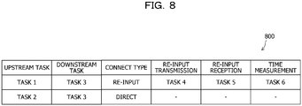
FIG. 8 . The connection configuration table 800 is implemented by, for example, a storage area such as thememory 502, therecording medium 505, or the like of thecontrol device 101 illustrated inFIG. 5 . -
FIG. 8 is an explanatory diagram illustrating an example of the stored contents of the connection configuration table 800. As illustrated inFIG. 8 , the connection configuration table 800 includes fields of upstream task, downstream task, connection type, re-input transmission, re-input reception, and time measurement. In the connection configuration table 800, connection configuration information is stored as a record by setting information in each field for each connection point. - A task name of an upstream task that forms a connection point is set in the field of upstream task. A task name of a downstream task that forms a connection point is set in the field of downstream task. Information indicating whether the connection type of a connection point is the direct configuration or the re-input configuration is set in the field of connection type. A task name of a re-input transmission task in the re-input configuration is set in the field of re-input transmission. A task name of a re-input reception task in the re-input configuration is set in the field of re-input reception. A task name of a time measurement task in the re-input configuration is set in the field of time measurement.
- Next, an example of the contents stored in a threshold table 900 will be described with reference to
FIG. 9 . The threshold table 900 is implemented by, for example, a storage area such as thememory 502, therecording medium 505, or the like of thecontrol device 101 illustrated inFIG. 5 . -
FIG. 9 is an explanatory diagram illustrating an example of the contents stored in the threshold table 900. As illustrated inFIG. 9 , the threshold table 900 has fields of direct→re-input change and re-input→direct change. The threshold table 900 stores threshold information by setting information in each field. - A first threshold used to determine whether to change the connection configuration of the
stream processing infrastructure 200 from the direct configuration to the re-input configuration is set in the field of direct->re-input change. A second threshold used to determine whether to change the connection configuration of thestream processing infrastructure 200 from the re-input configuration to the direct configuration is set in the field of re-input→direct change. - Here, when the first threshold is equal to the second threshold, there is a relatively high probability that the waiting time will be less than the second threshold immediately after the waiting time becomes equal to or more than the first threshold. Therefore, the switching frequency of the connection configuration of the
stream processing infrastructure 200 tends to increase. Then, the burden on thearithmetic device 103 is increased. For this reason, it is preferable that the first threshold be larger than the second threshold, for example. - Next, an example of the hardware configuration of the
storage device 102 will be described with reference toFIG. 10 . -
FIG. 10 is a block diagram illustrating an example of the hardware configuration of thestorage device 102. InFIG. 10 , thestorage device 102 includes aCPU 1001, amemory 1002, a network I/F 1003, a recording medium I/F 1004, and arecording medium 1005, which are interconnected by abus 1000. TheCPU 1001 to therecording medium 1005 included in thestorage device 102 are the same as theCPU 501 to therecording medium 505 included in thecontrol device 101 illustrated inFIG. 5 , and therefore, explanation thereof will not be repeated. - The
storage device 102 may include, for example, a keyboard, a mouse, a display, a printer, a scanner, a microphone, a speaker, etc., in addition to the above-described components. Further, thestorage device 102 may include a plurality of recording medium I/Fs 1004 andrecording media 1005. Further, thestorage device 102 may not have the recording medium I/F 1004 or therecording medium 1005. - Next, an example of the hardware configuration of the
arithmetic device 103 will be described with reference toFIG. 11 . -
FIG. 11 is a block diagram illustrating an example of the hardware configuration of thearithmetic device 103. InFIG. 11 , thearithmetic device 103 includes aCPU 1101, amemory 1102, a network I/F 1103, a recording medium I/F 1104, and arecording medium 1105, which are interconnected by abus 1100. TheCPU 1101 to therecording medium 1105 included in thearithmetic device 103 are the same as theCPU 501 to therecording medium 505 included in thecontrol device 101 illustrated inFIG. 5 and therefore, explanation thereof will not be repeated. - The
arithmetic device 103 may include, for example, a keyboard, a mouse, a display, a printer, a scanner, a microphone, a speaker, etc., in addition to the above-described components. Further, thearithmetic device 103 may include a plurality of recording medium I/Fs 1104 andrecording media 1105. Thearithmetic device 103 may not have the recording medium I/F 1104 or therecording medium 1105. - Next, an example of the contents stored in an internal state table 1200 will be described with reference to
FIG. 12 . The internal state table 1200 is implemented by, for example, a storage area such as thememory 502, therecording medium 505, or the like of thecontrol device 101 illustrated inFIG. 5 . -
FIG. 12 is an explanatory diagram illustrating an example of the stored contents of the internal state table 1200. As illustrated inFIG. 12 , the internal state table 1200 includes fields of task ID, task type, configuration change flag, internal waiting message list, operation program binary, upstream task, downstream task, and internal state value. The internal state table 1200 stores internal state information as a record by setting information in each field for eachtask 202. - A task ID is set in the field of task ID. Information indicating whether the task type is a direct transmission task, a re-input task, a re-input transmission task, a re-input reception task, or a time measurement task is set in the field of task type. A flag indicating whether or the configuration is being changed is set in the field of configuration change flag. A list that collects temporarily held messages is set in the field of internal waiting message list.
- An executable program to be the
task 202 is set in the field of operation program binary. A task name of an upstream task is set in the field of upstream task. A task name of a downstream task is set in the field of downstream task. An internal state value is set in the field of internal state value. The internal state values are location and temp. The location is a position. The temp is a temperature. - Next, an example of the functional configuration of the
information processing system 100 in which data is processed in a stream processing format will be described with reference toFIG. 13 . -
FIG. 13 is a block diagram illustrating an example of the functional configuration of theinformation processing system 100. The information processing system includes acontrol device 101, a plurality ofstorage devices 102 that implement a plurality ofdata stores 201, and a plurality ofarithmetic devices 103 that implement a plurality ofprocessing units 1321. - Each of the
processing units 1321 is a functional unit that implements the task. The functional unit that implements the task may be, for example, thearithmetic device 103 itself. Theinformation processing system 100 includes at least a firstarithmetic device 103, a secondarithmetic device 103, a thirdarithmetic device 103, a fourtharithmetic device 103, and a fiftharithmetic device 103. - Here, the plurality of
storage devices 102 implement, for example, at least afirst data store 201, asecond data store 201, and athird data store 201. Further, the plurality ofarithmetic devices 103 implement, for example, at least afirst processing unit 1321, asecond processing unit 1321, afirst relay unit 1322, and asecond relay unit 1322. - In the
information processing system 100, eachstorage device 102 includes afirst storage unit 1310 and aninput unit 1311. Thefirst storage unit 1310 is implemented by, for example, a storage area such as thememory 1002, therecording medium 1005, or the like illustrated inFIG. 10 . A case where thefirst storage unit 1310 is included in thestorage device 102 will be described below, but the present disclosure is not limited thereto. For example, thefirst storage unit 1310 may be included in a device different from thestorage device 102, and the stored contents of thefirst storage unit 1310 may be referred to by thestorage device 102. - The
input unit 1311 functions as an example of a controller of thestorage device 102. Specifically, theinput unit 1311 implements its function by, for example, causing theCPU 1001 to execute a program stored in a storage area such as thememory 1002, therecording medium 1005, or the like illustrated inFIG. 10 , or by the network I/F 1003. The processing result of theinput unit 1311 is stored in, for example, a storage area such as thememory 1002, therecording medium 1005, or the like illustrated inFIG. 10 . - The
first storage unit 1310 stores a variety of information that is referred to or updated in a process of theinput unit 1311. Thefirst storage unit 1310 stores, for example, data to be output. - The
input unit 1311 acquires a variety of information. Theinput unit 1311 stores the acquired variety of information in thefirst storage unit 1310, or outputs the information. Further, theinput unit 1311 may output the variety of information stored in thefirst storage unit 1310. Theinput unit 1311 acquires the variety of information based on, for example, a user's operation input. Theinput unit 1311 may receive a variety of information from, for example, a device different from thestorage device 102. - The
input unit 1311 acquires data from, for example, a data source and stores the data in thefirst storage unit 1310. Theinput unit 1311 acquires data from, for example, thearithmetic device 103 and stores the data in thefirst storage unit 1310. Theinput unit 1311 outputs, for example, data to be output, which is stored in a storage unit, to a path to thearithmetic device 103. - Specifically, when the
storage device 102 implements thefirst data store 201, theinput unit 1311 outputs data to a path connected to thefirst processing unit 1321. Specifically, when thestorage device 102 implements thesecond data store 201, theinput unit 1311 outputs data to a path connected to thesecond processing unit 1321. Specifically, when thestorage device 102 implements thethird data store 201, theinput unit 1311 transmits received data to a path to thesecond relay unit 1322 connected to thesecond processing unit 1321. The first,second relay units 1322 are implemented by, for example, the fourth, fiftharithmetic devices 103, respectively. - The
input unit 1311 acquires, for example, various requests from thecontrol device 101. Theinput unit 1311 outputs, for example, the various requests acquired from thecontrol device 101 to a path to thearithmetic device 103. Specifically, when thestorage device 102 implements thefirst data store 201, theinput unit 1311 outputs various requests to a path connected to thefirst processing unit 1321. Specifically, when thestorage device 102 implements thesecond data store 201, theinput unit 1311 outputs various requests to a path connected to thesecond processing unit 1321. Specifically, when thestorage device 102 implements thethird data store 201, theinput unit 1311 transmits received various requests to a path to thesecond relay unit 1322 connected to thesecond processing unit 1321. - Specifically, the
input unit 1311 acquires and outputs an output request to output a barrier marker, from thecontrol device 101 by receiving the output request. The barrier marker is a message instructing the backup of the internal state. The barrier marker is output from any one of the plurality ofdata stores 201 and then is discarded without being input to anotherdata store 201 different from any one of the data stores 201. - Specifically, the
input unit 1311 acquires and outputs a switching request to switch the output destination of theprocessing unit 1321. More specifically, theinput unit 1311 acquires and outputs the output destination of thefirst processing unit 1321 by receiving a switching request to switch to thesecond processing unit 1321. More specifically, theinput unit 1311 acquires and outputs the output destination of thefirst processing unit 1321 by receiving a switching request to switch to thefirst relay unit 1322. - Specifically, the
input unit 1311 acquires and outputs a movement request to move thetask 202 between thearithmetic devices 103. The movement is to change thearithmetic device 103 that executes thetask 202. More specifically, theinput unit 1311 acquires and outputs thefirst task 202 by receiving a movement request to move thefirst task 202 from the firstarithmetic device 103 to the thirdarithmetic device 103. More specifically, theinput unit 1311 acquires and outputs thefirst task 202 by receiving a movement request to move thefirst task 202 from the thirdarithmetic device 103 to the firstarithmetic device 103. - Specifically, when the
storage device 102 implements thethird data store 201, theinput unit 1311 receives and acquires processing information that defines the processing contents of thefirst task 202. The processing information defines, for example, the processing contents of thefirst task 202. Specifically, when thestorage device 102 implements thethird data store 201, theinput unit 1311 transmits received processing information to a path to thesecond relay unit 1322 connected to thesecond processing unit 1321. - The
input unit 1311 may receive a start trigger for starting a process of theinput unit 1311. The start trigger is, for example, that a user has input a predetermined operation. The start trigger may be, for example, reception of predetermined information from another computer. The start trigger is, for example, reception of data from a data source. The start trigger is, for example, reception of various requests from thecontrol device 101. - In the
information processing system 100, thearithmetic device 103 includes asecond storage unit 1320 and aprocessing unit 1321 or arelay unit 1322. Thesecond storage unit 1320 is implemented by, for example, a storage area such as thememory 1102, therecording medium 1105, or the like illustrated inFIG. 11 . A case where thesecond storage unit 1320 is included in thearithmetic device 103 will be described below, but the present disclosure is not limited thereto. For example, thesecond storage unit 1320 may be included in a device different from thearithmetic device 103, and the stored contents of thesecond storage unit 1320 may be referred to by thearithmetic device 103. - The
processing unit 1321 or therelay unit 1322 functions as an example of a controller of thearithmetic device 103. Specifically, theprocessing unit 1321 and therelay unit 1322 implement their functions by, for example, causing theCPU 1101 to execute a program stored in a storage area such as thememory 1102, therecording medium 1105, or the like illustrated inFIG. 11 , or by the network I/F 1103. - Specifically, the
processing unit 1321 operates as either thefirst processing unit 1321 or thesecond processing unit 1321. Specifically, therelay unit 1322 operates as either thefirst relay unit 1322 or thesecond relay unit 1322. The processing results of theprocessing unit 1321 and therelay unit 1322 are stored in, for example, a storage area such as thememory 1102, therecording medium 1105, or the like illustrated inFIG. 11 . - The
second storage unit 1320 stores a variety of information that is referred to or updated in the process of theprocessing unit 1321 or therelay unit 1322. Thesecond storage unit 1320 stores, for example, data to be output. Thesecond storage unit 1320 stores, for example, the internal state of theprocessing unit 1321. Specifically, thesecond storage unit 1320 stores the internal state of thetask 202. More specifically, thesecond storage unit 1320 stores the internal state table 1200. - The
processing unit 1321 acquires a variety of information. Theprocessing unit 1321 stores the acquired variety of information in thesecond storage unit 1320, or outputs the information. In addition, theprocessing unit 1321 may output the variety of information stored in thesecond storage unit 1320. Theprocessing unit 1321 acquires the variety of information based on, for example, a user's operation input. Theprocessing unit 1321 may receive a variety of information from, for example, a device different from thearithmetic device 103. - The
processing unit 1321 acquires data from, for example, thestorage device 102 or from otherarithmetic device 103, and stores the data in thefirst storage unit 1310. Theprocessing unit 1321 outputs, for example, data to be output, which is stored in thefirst storage unit 1310, to a path to thearithmetic device 103. - The
processing unit 1321 acquires a barrier marker from, for example, thestorage device 102 or from otherarithmetic device 103. Theprocessing unit 1321 performs the backup of the internal state in response to receiving barrier markers as many as the number of paths through which data is input. For example, theprocessing unit 1321 outputs the barrier markers to the respective paths to which data is output, in response to receiving barrier markers as many as the number of paths to which data is input. - The
processing unit 1321 acquires various requests from, for example, thestorage device 102 or from otherarithmetic device 103. Specifically, theprocessing unit 1321 acquires and outputs a switching request to switch the output destination of theprocessing unit 1321. More specifically, theprocessing unit 1321 acquires and outputs the output destination of thefirst processing unit 1321 by receiving a switching request to switch to thesecond processing unit 1321. When theprocessing unit 1321 operates as thefirst processing unit 1321, a switching request to switch the output destination of thefirst processing unit 1321 to thesecond processing unit 1321 is input from thesecond relay unit 1322. Then, after the switching request is input, theprocessing unit 1321 switches the output destination of thefirst processing unit 1321 from thefirst relay unit 1322 to thesecond processing unit 1321. - More specifically, the
processing unit 1321 acquires and outputs the output destination of thefirst processing unit 1321 by receiving a switching request to switch to thefirst relay unit 1322. When theprocessing unit 1321 operates as thefirst processing unit 1321, the switching request to switch the output destination of thefirst processing unit 1321 to thefirst relay unit 1322 is input from thesecond relay unit 1322. Then, after the switching request is input, theprocessing unit 1321 switches the output destination of thefirst processing unit 1321 from thefirst relay unit 1322 to thesecond processing unit 1321. - The
processing unit 1321 implements a data process. Theprocessing unit 1321 performs, for example, the data process of thetask 202 and outputs data of the processing result. Thefirst processing unit 1321 is, for example, thefirst task 202 that is executed by the firstarithmetic device 103 and performs a predetermined data process, and performs the data process of thefirst task 202. Thefirst processing unit 1321 may be executed by the thirdarithmetic device 103. Thesecond processing unit 1321 is, for example, thesecond task 202 that is executed by the secondarithmetic device 103 and performs a predetermined data process, and performs the data process of thesecond task 202. - When a movement request is received in the first
arithmetic device 103, theprocessing unit 1321 stores data received after the movement request. The movement request is a request to move thefirst task 202 from the firstarithmetic device 103 to the thirdarithmetic device 103. When the request is received in the thirdarithmetic device 103, theprocessing unit 1321 ends thefirst task 202. When the processing information is received, theprocessing unit 1321 implements the data process of thefirst task 202 based on the received processing information. - The
processing unit 1321 outputs, for example, the acquired various requests to a path to thearithmetic device 103. Specifically, theprocessing unit 1321 outputs the various requests to a path connected to thefirst processing unit 1321. Specifically, theprocessing unit 1321 outputs the various requests to a path connected to thesecond processing unit 1321. - When the
processing unit 1321 operates as thefirst processing unit 1321 in the firstarithmetic device 103, theprocessing unit 1321 transmits data of the processing result of thefirst task 202 to a path to the secondarithmetic device 103. When theprocessing unit 1321 does not operate as thefirst processing unit 1321 in the firstarithmetic device 103, theprocessing unit 1321 transmits the received data to a path to the thirdarithmetic device 103. - When the
processing unit 1321 operates as thefirst processing unit 1321 in the thirdarithmetic device 103, theprocessing unit 1321 transmits data of the processing result of thefirst task 202 to a path to thethird data store 201. Theprocessing unit 1321 transmits the received data in the fourtharithmetic device 103 to a path to the secondarithmetic device 103. - When a movement request is received in the first
arithmetic device 103, theprocessing unit 1321 transmits the received request to a path to the thirdarithmetic device 103. The movement request is a request to move thefirst task 202 from the firstarithmetic device 103 to the thirdarithmetic device 103. - When a movement request is received in the third
arithmetic device 103, theprocessing unit 1321 transmits processing information defining the processing contents of thefirst task 202 to a path to thethird data store 201. The movement request is a request to move thefirst task 202 from the thirdarithmetic device 103 to the firstarithmetic device 103. - When the processing information is received in the first
arithmetic device 103, theprocessing unit 1321 transmits data of the processing result of thefirst task 202 to a path to the secondarithmetic device 103. Theprocessing unit 1321 transmits the received processing information in the fourtharithmetic device 103 to a path to the firstarithmetic device 103. - The
relay unit 1322 acquires a variety of information. Therelay unit 1322 stores the acquired variety of information in thesecond storage unit 1320, or outputs the information. Further, therelay unit 1322 may output the variety of information stored in thesecond storage unit 1320. Therelay unit 1322 acquires the variety of information based on, for example, a user's operation input. Therelay unit 1322 may receive a variety of information from, for example, a device different from thearithmetic device 103. - When the
relay unit 1322 operates as thefirst relay unit 1322, therelay unit 1322 stores data input after the first switching request in thesecond storage unit 1320. The switching request is a request to switch the output destination of thefirst processing unit 1321 to thesecond processing unit 1321. When therelay unit 1322 operates as thefirst relay unit 1322, when a switching request is input from thesecond relay unit 1322 after the first switching request, therelay unit 1322 outputs the stored data to thesecond processing unit 1321. When therelay unit 1322 operates as thesecond relay unit 1322, therelay unit 1322 outputs the input switching request to thefirst processing unit 1321 and thefirst relay unit 1322. - The
relay unit 1322 may receive a start trigger that starts a process of therelay unit 1322. The start trigger is, for example, that a user has input a predetermined operation. The start trigger may be reception of predetermined information from another computer, for example. The start trigger is, for example, reception of data from thestorage device 102 or from otherarithmetic device 103. The start trigger is, for example, reception of a barrier marker from thestorage device 102 or from otherarithmetic device 103. The start trigger is, for example, reception of various requests from thestorage device 102 or from otherarithmetic device 103. - In the
information processing system 100, thecontrol device 101 includes athird storage unit 1330, anacquisition unit 1331, achange unit 1332, aBU instruction unit 1333, and anoutput unit 1334. Thethird storage unit 1330 is implemented by, for example, a storage area such as thememory 502, therecording medium 505, or the like illustrated inFIG. 5 . A case where thethird storage unit 1330 is included in thecontrol device 101 will be described below, but the present disclosure is not limited thereto. For example, thethird storage unit 1330 may be included in a device different from thecontrol device 101, and the stored contents of thethird storage unit 1330 may be referred to by thecontrol device 101. - The
acquisition unit 1331 to theoutput unit 1334 functions as an example of a controller of thecontrol device 101. Specifically, theacquisition unit 1331 to theoutput unit 1334 implement their functions by, for example, causing theCPU 501 to execute a program stored in a storage area such as thememory 502, therecording medium 505, or the like illustrated inFIG. 5 , or by the network I/F 503. The processing result of each functional unit is stored in, for example, a storage area such as thememory 502, therecording medium 505, or the like illustrated inFIG. 5 . - The
third storage unit 1330 stores a variety of information that is referred to or updated in a process of each functional unit. Thethird storage unit 1330 stores the connection relationship between thearithmetic devices 103. Thethird storage unit 1330 stores, for example, the connection relationship between thetasks 202. Thethird storage unit 1330 stores the first threshold and the second threshold. The first threshold is larger than the second threshold, for example. Specifically, thethird storage unit 1330 stores the connection configuration table 800 illustrated inFIG. 8 and the threshold table 900 illustrated inFIG. 9 . - The
acquisition unit 1331 acquires a variety of information used for a process of each functional unit. Theacquisition unit 1331 stores the acquired variety of information in thethird storage unit 1330 or outputs the information to each functional unit. Further, theacquisition unit 1331 may output the variety of information stored in thethird storage unit 1330 to each functional unit. Theacquisition unit 1331 acquires the variety of information based on, for example, a user's operation input. Theacquisition unit 1331 may receive a variety of information from, for example, an apparatus different from theinformation processing system 100. - The
acquisition unit 1331 acquires information about the waiting time until theprocessing unit 1321 receives barrier markers as many as the number of paths through which data is input to theprocessing unit 1321. Theacquisition unit 1331 acquires, for example, information about the waiting time regarding thesecond processing unit 1321. - The
acquisition unit 1331 may receive a start trigger for starting the process of any functional unit. The start trigger is, for example, that a user has a predetermined operation input. The start trigger may be, for example, reception of predetermined information from another computer. For example, theacquisition unit 1331 may periodically detect a timing of outputting a barrier marker to eachdata store 201. - The
change unit 1332 determines whether or not the waiting time is equal to or more than the first threshold, based on acquired information. When it is determined that the waiting time is equal to or more than the first threshold, thechange unit 1332 switches the connection configuration of thestream processing infrastructure 200 from the first configuration to the second configuration. The first configuration is a configuration in which thethird data store 201 is not included on the path from thefirst processing unit 1321 to thesecond processing unit 1321. The second configuration is a configuration in which thethird data store 201 is included on the path from thefirst processing unit 1321 to thesecond processing unit 1321. - A path from the
first processing unit 1321 to thesecond processing unit 1321 in the first configuration and a path from thefirst processing unit 1321 including thethird data store 201 to thesecond processing unit 1321 in the second configuration merge at thesecond processing unit 1321. Thechange unit 1332 may generate thethird data store 201 when it is determined that the waiting time is equal to or more than the first threshold. - For example, when it is determined that the waiting time is equal to or more than the first threshold, the
change unit 1332 switches the output destination of thefirst processing unit 1321 from thesecond processing unit 1321 to thefirst relay unit 1322 that outputs the input data. Thefirst relay unit 1322 is included on a path from thefirst processing unit 1321 to thethird data store 201. Specifically, when it is determined that the waiting time is equal to or more than the first threshold, thechange unit 1332 outputs from the first data store 201 a switching request to switch the output destination of thefirst processing unit 1321 from thesecond processing unit 1321 to thefirst relay unit 1322. - For example, when it is determined that the waiting time is equal to or more the first threshold, the
change unit 1332 may move thefirst task 202 from the firstarithmetic device 103 to the thirdarithmetic device 103 that is able to execute thefirst task 202. Specifically, when it is determined that the waiting time is equal to or more than the first threshold, thechange unit 1332 outputs from the first data store 201 a movement request to move thefirst task 202 from the firstarithmetic device 103 to the thirdarithmetic device 103 that is able to execute thefirst task 202. - The
change unit 1332 determines whether or not the waiting time is less than the second threshold, based on the acquired information. When it is determined that the waiting time is less than the second threshold, thechange unit 1332 switches from the second configuration to the first configuration. When it is determined that the waiting time is less than the second threshold, thechange unit 1332 switches the output destination of thefirst processing unit 1321 from thefirst relay unit 1322 to thesecond processing unit 1321. Specifically, when it is determined that the waiting time is less than the second threshold, thechange unit 1332 outputs from the first data store.201 a switching request to switch the output destination of thefirst processing unit 1321 to thesecond processing unit 1321. - For example, when it is determined that the waiting time is less than the second threshold, the
change unit 1332 may move thefirst task 202 from the thirdarithmetic device 103 to the firstarithmetic device 103. For example, when it is determined that the waiting time is less than the second threshold, thechange unit 1332 outputs from the first data store 201 a movement request to move thefirst task 202 from the thirdarithmetic device 103 to the firstarithmetic device 103. - The
BU instruction unit 1333 outputs a barrier marker from each of the plurality ofdata stores 201. - The
output unit 1334 outputs the processing result of any functional unit. The output format is, for example, display on a display, print output to a printer, transmission to an external device by the network I/F 503, storage in a storage area such as thememory 502, therecording medium 505 or the like. As a result, theoutput unit 1334 may notify the user of the processing result of any functional unit, which may result in improvement of the convenience of theinformation processing system 100. - Next, a specific example of the functional configuration of the
information processing system 100 will be described with reference toFIG. 14 . -
FIG. 14 is a block diagram illustrating a specific example of the functional configuration of theinformation processing system 100. In theinformation processing system 100, thearithmetic device 103 includes an inputdata reception unit 1411, aprocess execution unit 1412, an outputdata transmission unit 1413, a re-inputdata transmission unit 1414, acheckpoint management unit 1415, and a processingstatus monitoring unit 1416. Further, in theinformation processing system 100, thecontrol device 101 includes an arithmetic device operation monitoring unit 1400, a checkpointprogress management unit 1401, a connection configurationchange determination unit 1402, and a connection configurationchange instruction unit 1403. - The input
data reception unit 1411 receives adata message 600 from thedata store 201 or from otherarithmetic device 103. In addition, the inputdata reception unit 1411 receives various requests from thedata store 201 or from otherarithmetic device 103. Further, the inputdata reception unit 1411 receives processing information that defines the processing contents of thetask 202, from otherarithmetic device 103. - The
process execution unit 1412 executes a predetermined data process based on thedata message 600. Theprocess execution unit 1412 controls the outputdata transmission unit 1413 to output data of the processing result to otherarithmetic device 103. Alternatively, theprocess execution unit 1412 controls the re-inputdata transmission unit 1414 to output the data of the processing result to thedata store 201. When barrier markers are received as many as the number of paths through which data is input, theprocess execution unit 1412 activates thecheckpoint management unit 1415. When the barrier markers are received as many as the number of paths to which data is input, theprocess execution unit 1412 controls the outputdata transmission unit 1413 to output the barrier markers to otherarithmetic device 103. - The
process execution unit 1412 executes a process corresponding to the various requests. When the switching request or the movement request is received, theprocess execution unit 1412 controls the outputdata transmission unit 1413 or the re-inputdata transmission unit 1414 to transmit the switching request or the movement request to otherarithmetic device 103 or thedata store 201. When the switching request is received, theprocess execution unit 1412 controls the outputdata transmission unit 1413 or the re-inputdata transmission unit 1414 to switch the transmission destination. When the movement request is received, theprocess execution unit 1412 controls the outputdata transmission unit 1413 or the re-inputdata transmission unit 1414 to transmit the processing information defining the processing contents of thetask 202 to otherarithmetic device 103 or thedata store 201 in order to move thetask 202. - In addition, when the processing information is received, the
process execution unit 1412 implements thetask 202 based on the processing information. When the processing information is received, theprocess execution unit 1412 controls the outputdata transmission unit 1413 or the re-inputdata transmission unit 1414 to transmit the processing information to otherarithmetic device 103 or thedata store 201. - The output
data transmission unit 1413 transmits the data of the processing result, the switching request or the movement request, the processing information, the barrier marker, or the like to otherarithmetic device 103, an external computer, or the like under the control of theprocess execution unit 1412. The re-inputdata transmission unit 1414 transmits the data of the processing result, the switching request or the movement request, the processing information, or the like to thedata store 201 under the control of theprocess execution unit 1412. - When activated, the
checkpoint management unit 1415 saves the internal state table 1200 for eachtask 202, as acheckpoint 1420. After the internal state table 1200 for eachtask 202 is saved, thecheckpoint management unit 1415 transmits a save completion report to the checkpointprogress management unit 1401. The processingstatus monitoring unit 1416 measures the waiting time of the barrier marker in theprocess execution unit 1412, and transmits the waiting time to the connection configurationchange determination unit 1402. - The arithmetic device operation monitoring unit 1400 monitors a failure or the like of the
arithmetic device 103 and detects a timing for restoring thestream processing infrastructure 200 from the failure. The checkpointprogress management unit 1401 outputs a barrier marker from eachdata store 201. In addition, the checkpointprogress management unit 1401 collects and manages backup progress information in eacharithmetic device 103. For example, the checkpointprogress management unit 1401 collects the save completion report and manages the backup progress information in eacharithmetic device 103. - Based on the threshold table 900, the connection configuration
change determination unit 1402 determines whether or not the waiting time of the barrier marker in theprocess execution unit 1412 is equal to or more than the first threshold or less than the second threshold. For example, when the current connection configuration of thestream processing infrastructure 200 is the direct configuration, the connection configurationchange determination unit 1402 determines whether or not the waiting time is equal to or more than the first threshold. In addition, for example, when the current connection configuration of thestream processing infrastructure 200 is the re-input configuration, the connection configurationchange determination unit 1402 determines whether or not the waiting time is less than the second threshold. - When the current connection configuration of the
stream processing infrastructure 200 is the direct configuration, and it is determined that the waiting time is equal to or more than the first threshold, the connection configurationchange determination unit 1402 determines to change the connection configuration of thestream processing infrastructure 200 to the re-input configuration. Then, the connection configurationchange determination unit 1402 outputs to the connection configuration change instruction unit 1403 a switching request or a movement request that is a change instruction to change to the re-input configuration. - When the current connection configuration of the
stream processing infrastructure 200 is the re-input configuration, and it is determined that the waiting time is less than the second threshold, the connection configurationchange determination unit 1402 determines to change the connection configuration of thestream processing infrastructure 200 to the direct configuration. Then, the connection configurationchange determination unit 1402 outputs to the connection configuration change instruction unit 1403 a switching request or a movement request that is a change instruction to change to the direct configuration. - The connection configuration
change instruction unit 1403 outputs from thedata store 201 the switching request or the movement request that is a change instruction. The connection configurationchange instruction unit 1403 updates the connection configuration table 800 according to the changed connection configuration of thestream processing infrastructure 200. - Next, Example 1 of the
information processing system 100 will be described with reference toFIGs. 15 to 33 . First, in Example 1, an example of changing the connection configuration of thestream processing infrastructure 200 from the direct configuration to the re-input configuration will be described with reference toFIGs. 15 and16 . -
FIGs. 15 and16 are explanatory diagrams illustrating an example of changing the connection configuration of thestream processing infrastructure 200 from the direct configuration to the re-input configuration in Example 1. In the example ofFIGs. 15 and16 , there aredata stores 1501 to 1503 andtasks 1511 to 1513, 1521, and 1522. - The
task 1511 is a task that is relatively slow in operation. Thetask 1512 is a task that is relatively fast in operation. Thetask 1513 is a downstream task that receives data of the processing result of thetask 1511 and data of the processing result of thetask 1512. Thetask 1521 is a re-input transmission task. Thetask 1522 is a re-input reception task. - In
FIG. 15 , the connection configuration of thestream processing infrastructure 200 is a direct configuration. For example, thetask 1511 directly transmits the data of the processing result of thetask 1511 to thetask 1513. Further, for example, thetask 1512 directly transmits the data of the processing result of thetask 1512 to thetask 1513. - The
control device 101 acquires the waiting time of a barrier marker in thetask 1513. Here, it is assumed that the waiting time of the barrier marker in thetask 1513 is equal to or more than the first threshold, and thecontrol device 101 determines to change the connection configuration of thestream processing infrastructure 200 to a re-input configuration. Therefore, thecontrol device 101 forms a connection from thetask 1521 to thedata store 1503, a connection from thedata store 1503 to thetask 1522, and a connection from thetask 1522 to thetask 1513. Next, descriptions will be made while referring toFIG. 16 . - In
FIG. 16 , thecontrol device 101 deletes a connection from thetask 1511 to thetask 1513 and forms a connection from thetask 1511 to thetask 1521 at a timing of outputting a barrier marker from thedata stores 1501 to 1503. - As a result, the
control device 101 may reduce the waiting time of the barrier marker in thetask 1513. For example, since the barrier marker output from thedata stores task 1513, thecontrol device 101 may reduce the waiting time of the barrier marker in thetask 1513. - Next, in Example 1, an example of acquiring the waiting time of the barrier marker in the
task 1513 at the time of direct configuration after changing to the re-input configuration will be described with reference toFIG. 17 . In the example ofFIG. 17 , the waiting time of the barrier marker in thetask 1513 at the time of direct configuration is acquired in the connection configuration of thestream processing infrastructure 200 illustrated inFIG. 16 . -
FIG. 17 is an explanatory diagram illustrating an example of acquiring the waiting time. InFIG. 17 , since there is no connection from thetask 1511 to thetask 1513, thecontrol device 101 may not directly acquire the waiting time of the barrier marker in thetask 1513 at the time of direct configuration. - For this reason, the
control device 101 prepares atime measurement task 1700 and creates a connection from thetask 1511 to thetime measurement task 1700 and a connection from thetask 1512 to thetime measurement task 1700. Then, thecontrol device 101 acquires the waiting time of a barrier marker in thetime measurement task 1700 as the waiting time of the barrier marker in thetask 1513 at the time of direct configuration. - Accordingly, the
control device 101 may determine whether to change the connection configuration of thestream processing infrastructure 200 from the re-input configuration to the direct configuration. For example, thecontrol device 101 may measure the processing loads of thetasks tasks control device 101 may measure the data transmission/reception interval between thetask 1511 and thetask 1512 and estimate the waiting time based on the data transmission/reception interval between thetask 1511 and thetask 1512. - Next, in Example 1, an example of changing the connection configuration of the
stream processing infrastructure 200 from the re-input configuration to the direct configuration will be described with reference toFIGs. 18 to 23 . In the example ofFIGs. 18 to 23 , the connection configuration of thestream processing infrastructure 200 illustrated inFIG. 16 is changed from the re-input configuration to the direct configuration. -
FIGs. 18 to 23 are explanatory diagrams illustrating an example of changing the connection configuration of thestream processing infrastructure 200 from the re-input configuration to the direct configuration in Example 1. InFIG. 18 , since the waiting time of the barrier marker in thetask 1513 at the time of direct configuration is less than the second threshold, thecontrol device 101 determines to change the connection configuration of thestream processing infrastructure 200 from the re-input configuration to the direct configuration. - Here, the
control device 101 creates a connection from thetask 1511 to thetask 1513, a connection from thetask 1521 to thetask 1513, a connection from thetask 1522 to thetask 1511, and a connection from thetask 1522 to thetask 1521. Next, descriptions will be made while referring toFIG. 19 . - In
FIG. 19 , thecontrol device 101 outputs aconfiguration change message 700 from thedata store 1501. Theconfiguration change message 700 reaches thetask 1521 via thetask 1511. Thetask 1521 stores data after theconfiguration change message 700 without re-inputting thedata store 1503, and transmits theconfiguration change message 700 to thedata store 1503. Next, descriptions will be made while referring toFIG. 20 . - In
FIG. 20 , thedata store 1503 transmits theconfiguration change message 700 to thetask 1522 without overtaking data before theconfiguration change message 700. Thetask 1522 transmits to thetasks configuration change message 700 received from thedata store 1503. Next, descriptions will be made while referring toFIG. 21 . - In
FIG. 21 , thetask 1511 holds theconfiguration change message 700. Thetask 1521 sequentially transmits the stored data to thetask 1513. Here, since thedata store 1503 prevents theconfiguration change message 700 from overtaking the data before theconfiguration change message 700, the data order is secured even when thetask 1521 transmits the stored data. Next, descriptions will be made while referring toFIG. 22 . - In
FIG. 22 , thestream processing infrastructure 200 is operated so that data is transmitted from thetask 1511 to thetask 1513 via thetask 1521 until the barrier marker is output from thedata store 1501. Next, descriptions will be made while referring toFIG. 23 . - In
FIG. 23 , when the barrier marker is received, thetask 1511 switches the transmission destination to thetask 1513 based on theconfiguration change message 700. Since the data after the barrier marker does not overtake the data before the barrier marker, the data order is secured. After that, thecontrol device 101 may remove thetasks - Accordingly, the
control device 101 may change the connection configuration of thestream processing infrastructure 200 from the re-input configuration to the direct configuration while ensuring the data order. Therefore, when it is determined that the waiting time of the barrier marker in thetask 1513 at the time of direct configuration is relatively short, thecontrol device 101 may prevent the processing delay caused by re-inputting data into thedata store 1503. - Next, an example of comparing the processing delay in the direct configuration and the processing delay in the re-input configuration will be described with reference to
FIGs. 24 to 27 . -
FIGs. 24 to 27 are explanatory diagrams illustrating an example of comparing the processing delay in the direct configuration with the processing delay in the re-input configuration. The example ofFIG. 24 illustrates adirect configuration 2400 and are-input configuration 2420 of thestream processing infrastructure 200. The tasks common to thedirect configuration 2400 and there-input configuration 2420 are denoted by the same reference numerals. - The
direct configuration 2400 includesdata stores tasks 2411 to 2413. Thetask 2411 is a task that is relatively slow in operation. Thetask 2412 is a task that is relatively fast in operation. Thetask 2413 is a downstream task that receives data of the processing result of thetask 2411 and data of the processing result of thetask 2412. In thedirect configuration 2400, there is a connection from thedata store 2401 to thetask 2411, a connection from thedata store 2402 to thetask 2412, a connection from thetask 2411 to thetask 2413, and a connection from thetask 2412 to thetask 2413. - The
re-input configuration 2420 includesdata stores 2401 to 2403,tasks 2411 to 2413, andtasks task 2431 is a re-input transmission task. Thetask 2432 is a re-input reception task. - In the
re-input configuration 2420, there are a connection from thedata store 2401 to thetask 2411, a connection from thetask 2411 to thetask 2431, and a connection from thetask 2431 to thedata store 2403. In addition, there is a connection from thedata store 2403 to thetask 2432 and a connection from thetask 2432 to thetask 2413. Further, there is a connection from thedata store 2402 to thetask 2412 and a connection from thetask 2412 to thetask 2413. Next, descriptions will be made while referring toFIG. 25 . - In
FIG. 25 , it is assumed that in thedirect configuration 2400, barrier markers are output from thedata stores 2401 and 4022, and in there-input configuration 2420, barrier markers are output from thedata stores 2401 to 2403. Next, descriptions will be made while referring toFIG. 26 . - In
FIG. 26 , the barrier marker propagates over time. In both thedirect configuration 2400 and there-input configuration 2420, since thetask 2411 is relatively slow in operation, the propagation of the barrier marker is stagnated in thetask 2411. - For this reason, in the
direct configuration 2400, even when thetask 2413 receives the barrier marker output by thedata store 2402, thetask 2413 waits until thetask 2413 receives the barrier marker output by thedata store 2401 without performing a predetermined data process. As a result, thedirect configuration 2400 results in increase of the waiting time of the barrier marker at thetask 2413. - In contrast, in the
re-input configuration 2420, thetask 2413 may receive the barrier marker output by thedata store 2402 and the barrier marker output by thedata store 2403, so that the predetermined data process may be performed relatively early. Therefore, there-input configuration 2420 may suppress an increase in the waiting time of the barrier marker. Next, descriptions will be made while referring toFIG. 27 . - In
FIG. 27 , thedirect configuration 2400 causes an increase in the waiting time of the barrier marker in thetask 2413, which causes the processing delay for data after the barrier marker output by thedata store 2402. Meanwhile, there-input configuration 2420 may suppress the processing delay for the data after the barrier marker output by thedata store 2402 in thetask 2413. - Next, an example of the overall processing procedure in Example 1 executed by the
control device 101 will be described with reference toFIG. 28 . The overall processing is implemented by, for example, theCPU 501, a storage area such as thememory 502, therecording medium 505, or the like, and the network I/F 503 illustrated inFIG. 5 . -
FIG. 28 is a flowchart illustrating an example of the overall processing procedure in Example 1. InFIG. 28 , thecontrol device 101 waits until a checkpoint processing is completed (operation S2801). - Next, the
control device 101 acquires the waiting time of a barrier marker (operation S2802). Then, thecontrol device 101 selects an unprocessed connection point (operation S2803). - Next, the
control device 101 determines whether or not the connection type of the connection configuration of the selected connection point is the direct configuration (operation S2804). Here, in the case of the direct configuration (Yes in operation S2804), thecontrol device 101 proceeds to the processing of operation S2805. Meanwhile, in the case of the re-input configuration rather than the direct configuration (No in operation S2804), thecontrol device 101 proceeds to the processing of operation S2808. - In operation S2805, the
control device 101 determines whether or not the waiting time of the downstream task is equal to or more than the first threshold (operation S2805). Here, when it is determined that the waiting time is equal to or more than the first threshold (Yes in operation S2805), thecontrol device 101 proceeds to the processing of operation S2806. Meanwhile, when it is determined that the waiting time is not equal to or more than the first threshold (No in operation S2805), thecontrol device 101 proceeds to the processing of operation S2811. - In operation S2806, the
control device 101 updates the connection configuration to the re-input configuration (operation S2806). Next, thecontrol device 101 transmits an instruction to change to the re-input configuration (operation S2807). The instruction to change to the re-input configuration is, for example, a configuration change message. Then, thecontrol device 101 proceeds to the processing of operation S2811. - In operation S2808, the
control device 101 determines whether or not the waiting time of the measurement task is equal to or less than the second threshold (operation S2808). Here, when it is determined that the waiting time is equal to or less than the second threshold (Yes in operation S2808), thecontrol device 101 proceeds to the processing of operation S2809. Meanwhile, when it is determined that the waiting time is not equal to or less than the second threshold (No in operation S2808), thecontrol device 101 proceeds to the processing of operation S2811. - In operation S2809, the
control device 101 updates the connection configuration to the direct configuration (operation S2809). Next, thecontrol device 101 transmits an instruction to change to the direct configuration (operation S2810). The instruction to change to the direct configuration is, for example, a configuration change message. Then, thecontrol device 101 proceeds to the processing of operation S2811. - In operation S2811, the
control device 101 determines whether or not all the connection points have been selected (operation S2811). When it is determined that there is an unselected connection point (No in operation S2811), thecontrol device 101 returns to the processing of operation S2803. When it is determined that all the connection points have been selected (Yes in operation S2811), thecontrol device 101 returns to the processing of operation S2801. - Next, an example of the change instruction processing procedure in Example 1 executed by the
control device 101 will be described with reference toFIG. 29 . The change instruction processing is implemented by, for example, theCPU 501, a storage area such as thememory 502, therecording medium 505, or the like, and the network I/F 503 illustrated inFIG. 5 . -
FIG. 29 is a flowchart illustrating an example of the change instruction processing procedure in Example 1. InFIG. 29 , thecontrol device 101 waits until a change instruction is received (operation S2901). - Next, the
control device 101 determines whether or not the type of the change instruction is a re-input configuration (operation S2902). Here, when it is determined that the type of the change instruction is the re-input configuration (Yes in operation S2902), thecontrol device 101 proceeds to the processing of operation S2903. Meanwhile, when it is determined that the type of the change instruction is not the re-input configuration (No in operation S2902), thecontrol device 101 proceeds to the processing of operation S2906. - In operation S2903, the
control device 101 creates a re-input transmission task and a re-input reception task (operation S2903). Next, thecontrol device 101 forms a path connected to the re-input transmission task and a path connected to the re-input reception task (operation S2904). Then, thecontrol device 101 transmits aconfiguration change message 700 for changing to the re-input configuration (operation S2905). Then, thecontrol device 101 returns to the processing of operation S2901. - In operation S2906, the
control device 101 transmits aconfiguration change message 700 for changing to the direct configuration (operation S2906). Next, thecontrol device 101 waits until the configuration change is completed (operation S2907). Then, thecontrol device 101 removes the re-input transmission task, the re-input reception task, the path connected to the re-input transmission task, and the path connected to the re-input reception task (operation S2908). Then, thecontrol device 101 returns to the processing of operation S2901. - Next, an example of the task processing procedure in Example 1 executed by the
arithmetic device 103 will be described with reference toFIGs. 30 and31 . The task processing is implemented by, for example, theCPU 1101, a storage area such as thememory 1102, therecording medium 1105, or the like, and the network I/F 1103 illustrated inFIG. 11 . -
FIGs. 30 and31 are flowcharts illustrating an example of the task processing procedure in Example 1. InFIG. 30 , thearithmetic device 103 waits until a message is received (operation S3001). - Next, the
arithmetic device 103 determines whether or not the type of the message is a data message 600 (operation S3002). Here, when it is determined that the type of the message is the data message 600 (Yes in operation S3002), thearithmetic device 103 proceeds to the processing of operation S3003. Meanwhile, when it is determined that the type of the message is not the data message 600 (No in operation S3002), thearithmetic device 103 proceeds to the processing of operation S3005. - In operation S3003, the
arithmetic device 103 executes a normal process (operation S3003). Next, thearithmetic device 103 transmits thedata message 600 according to the normal process (operation S3004). Then, thearithmetic device 103 returns to the processing of operation S3001. - In operation S3005, the
arithmetic device 103 determines whether or not the type of the message is aconfiguration change message 700 addressed to the own device (operation S3005). Here, when it is determined that the type of the message is theconfiguration change message 700 addressed to the own device (Yes in operation S3005), thearithmetic device 103 proceeds to the processing of operation S3006. Meanwhile, when it is determined that the type of the message is not theconfiguration change message 700 addressed to the own device (No in operation S3005), thearithmetic device 103 proceeds to the processing of operation S3007. - In operation S3006, the
arithmetic device 103 transfers theconfiguration change message 700 according to route information of the configuration change message 700 (operation S3006). Then, thearithmetic device 103 returns to the processing of operation S3001. - In operation S3007, the
arithmetic device 103 determines whether or not the type of the message is aconfiguration change message 700 for changing to the re-input configuration (operation S3007). Here, when it is determined that the type of the message is theconfiguration change message 700 for changing to the re-input configuration (Yes in operation S3007), thearithmetic device 103 proceeds to the processing of operation S3008. Meanwhile, when it is determined that the type of the message is not theconfiguration change message 700 for changing to the re-input configuration (No in operation S3007), thearithmetic device 103 proceeds to the processing of operation S3009. - In operation S3008, the
arithmetic device 103 changes the transmission destination of subsequent messages to the re-input transmission task (operation S3008). Then, thearithmetic device 103 returns to the processing of operation S3001. - In operation S3009, the
arithmetic device 103 determines whether or not the type of the message is aconfiguration change message 700 for changing to the direct configuration (operation S3009). Here, when it is determined that the type of the message is theconfiguration change message 700 for changing to the direct configuration (Yes in operation S3009), thearithmetic device 103 temporarily holds the configuration change message 700 (operation S3010). Then, thearithmetic device 103 returns to the processing of operation S3001. - Meanwhile, when it is determined that the type of the message is not the
configuration change message 700 for changing to the direct configuration (No in operation S3009), thearithmetic device 103 proceeds to operation S3101 inFIG. 31 . - In
FIG. 31 , thearithmetic device 103 temporarily holds a barrier marker (operation S3101). Next, thearithmetic device 103 determines whether or not barrier markers have arrived from all the upstream tasks (operation S3102). Here, when it is determined that the barrier markers have arrived from all the upstream tasks (Yes in operation S3102), thearithmetic device 103 proceeds to the processing of operation S3103. Meanwhile, when it is determined that the barrier markers have not arrived from any of the upstream tasks (No in operation S3102), thearithmetic device 103 returns to the processing of operation S3001. - In operation S3103, the
arithmetic device 103 determines whether or not theconfiguration change message 700 is temporarily held (operation S3103). Here, in the case of being temporarily held (Yes in operation S3103), thearithmetic device 103 proceeds to the processing of operation S3104. Meanwhile, in the case of not being temporarily held (No in operation S3103), thearithmetic device 103 proceeds to the processing of operation S3105. - In operation S3104, the
arithmetic device 103 changes the transmission destination of subsequent messages to the original downstream task (operation S3104). Then, thearithmetic device 103 proceeds to the processing of operation S3105. - In operation S3105, the
arithmetic device 103 performs a checkpoint process, discards the temporarily held barrier marker, and transmits the barrier marker to the downstream (operation S3105). Then, thearithmetic device 103 returns to the processing of operation S3001. - Next, an example of the re-input processing procedure in Example 1 executed by the
arithmetic device 103 will be described with reference toFIG. 32 . The re-input processing is implemented by, for example, theCPU 1101, a storage area such as thememory 1102, therecording medium 1105, or the like, and the network I/F 1103 illustrated inFIG. 11 . -
FIG. 32 is a flowchart illustrating an example of the re-input processing procedure in Example 1. InFIG. 32 , thearithmetic device 103 waits until a message is received (operation S3201). - Next, the
arithmetic device 103 determines whether or not the type of the message is aconfiguration change message 700 addressed to the own device (operation S3202). Here, when it is determined that the type of the message is theconfiguration change message 700 addressed to the own device (Yes in operation S3202), thearithmetic device 103 proceeds to the processing of operation S3203. Meanwhile, when it is determined that the type of the message is not theconfiguration change message 700 addressed to the own device (No in operation S3202), thearithmetic device 103 proceeds to the processing of operation S3208. - In operation S3203, the
arithmetic device 103 determines whether or not a configuration change flag is "on" (operation S3203). Here, in the case of being "on" (Yes in operation S3203), thearithmetic device 103 proceeds to the processing of operation S3204. Meanwhile, in the case of being "off" (No in operation S3203), thearithmetic device 103 proceeds to the processing of operation S3207. - In operation S3204, the
arithmetic device 103 transmits the stored message to the downstream (operation S3204). Next, thearithmetic device 103 changes the transfer destination of the message to the downstream task (operation S3205). Then, thearithmetic device 103 changes the configuration change flag to "off" (operation S3206). Then, thearithmetic device 103 returns to the processing of operation S3201. - In operation S3207, the
arithmetic device 103 changes the configuration change flag to "on" (operation S3207). Then, thearithmetic device 103 returns to the processing of operation S3201. - In operation S3208, the
arithmetic device 103 determines whether or not the configuration change flag is "on" (operation S3208). Here, in the case of being "on" (Yes in operation S3208), thearithmetic device 103 proceeds to the processing of operation S3209. Meanwhile, in the case of being "off (No in operation S3208), thearithmetic device 103 proceeds to the processing of operation S3210. - In operation S3209, the
arithmetic device 103 stores the message therein (operation S3209). Then, thearithmetic device 103 returns to the processing of operation S3201. - In operation S3210, the
arithmetic device 103 transfers the message (operation S3210). Then, thearithmetic device 103 returns to the processing of operation S3201. - Next, an example of the reception processing procedure in Example 1 executed by the
arithmetic device 103 will be described with reference toFIG. 33 . The reception processing is implemented by, for example, theCPU 1101, a storage area such as thememory 1102, therecording medium 1105, or the like, and the network I/F 1103 illustrated inFIG. 11 . -
FIG. 33 is a flowchart illustrating an example of the reception processing procedure in Example 1. InFIG. 33 , thearithmetic device 103 waits until a message is received (operation S3301). - Next, the
arithmetic device 103 determines whether or not the type of the message is aconfiguration change message 700 addressed to the own device (operation S3302). Here, when it is determined that the type of the message is theconfiguration change message 700 addressed to the own device (Yes in operation S3302), thearithmetic device 103 proceeds to the processing of operation S3303. Meanwhile, when it is determined that the type of the message is not theconfiguration change message 700 addressed to the own device (No in operation S3302), thearithmetic device 103 proceeds to the processing of operation S3304. - In operation S3303, the
arithmetic device 103 transmits theconfiguration change message 700 to the upstream task and the re-input transmission task (operation S3303). Then, thearithmetic device 103 returns to the processing of operation S3301. - In operation S3304, the
arithmetic device 103 transfers the message (operation S3304). Then, thearithmetic device 103 returns to the processing of operation S3301. - Next, Example 2 of the
information processing system 100 will be described with reference toFIGs. 34 to 43 . Example 2 is an example in which thearithmetic device 103 may output a task dump and dynamically change the processing contents, and the task may be moved between thearithmetic devices 103. First, an example of changing the connection configuration of thestream processing infrastructure 200 from a direct configuration to a re-input configuration in Example 2 will be described with reference toFIGs. 34 and35 . -
FIGs. 34 and35 are explanatory diagrams illustrating an example of changing the connection configuration of thestream processing infrastructure 200 from the direct configuration to the re-input configuration in Example 2. In the example ofFIGs. 34 and35 , there aredata stores 3401 to 3403 andarithmetic devices 3411 to 3417. - The
arithmetic device 3411 executes a task T1 that is relatively slow in operation. Thearithmetic device 3415 executes a task T2 that is relatively fast in operation. Thearithmetic device 3414 executes a downstream task T3 that receives data of the processing result of the task T1 and data of the processing result of the task T2. Thearithmetic device 3417 executes a time measurement task T4. - In
FIG. 34 , the connection configuration of thestream processing infrastructure 200 is a direct configuration. For example, there is a connection from thedata store 3401 to thearithmetic device 3411. There is also a connection from thedata store 3402 to thearithmetic device 3415. There is also a connection from thearithmetic device 3411 to thearithmetic device 3412, thearithmetic device 3414, and thearithmetic device 3417. There is also a connection from thearithmetic device 3412 to thedata store 3403. - In addition, there is a connection from the
arithmetic device 3415 to thearithmetic device 3416, thearithmetic device 3414, and thearithmetic device 3417. There is also a connection from thearithmetic device 3416 to thedata store 3403. There is also a connection from thedata store 3403 to thearithmetic device 3413. There is also a connection from thearithmetic device 3413 to thearithmetic device 3411, thearithmetic device 3412, thearithmetic device 3414, thearithmetic device 3415, and thearithmetic device 3416. - The
arithmetic device 3411 transmits data of the processing result of the task T1 to thearithmetic device 3414 that executes the task T3, via the connection from thearithmetic device 3411 to thearithmetic device 3414. Further, for example, thearithmetic device 3415 transmits data of the processing result of the task T2 to thearithmetic device 3414 that executes the task T3, via the connection from thearithmetic device 3415 to thearithmetic device 3414. - The
control device 101 acquires the waiting time of a barrier marker in the task T3. Here, it is assumed that the waiting time of the barrier marker in the task T3 is equal to or more than the first threshold, and thecontrol device 101 determines to change the connection configuration of thestream processing infrastructure 200 to a re-input configuration. Next, descriptions will be made while referring toFIG. 35 . - In
FIG. 35 , thecontrol device 101 moves the task T1 to thearithmetic device 3412. After the task T1 is moved, thearithmetic device 3411 operates so as to transfer input data, as it is, to thearithmetic device 3412. Thearithmetic device 3412 transmits the data of the processing result of the task T1 to thedata store 3403 via the connection from thearithmetic device 3412 to thedata store 3403. Thereafter, the data of the processing result of the task T1 is re-input from thedata store 3403 and is transmitted to thearithmetic device 3414 via thearithmetic device 3413. - As a result, the
control device 101 may reduce the waiting time of the barrier marker in the task T3. For example, since the barrier markers output from thedata stores control device 101 may reduce the waiting time of the barrier marker in the task T3. - Next, an example of changing the connection configuration of the
stream processing infrastructure 200 from the re-input configuration to the direct configuration in Example 2 will be described with reference toFIGs. 36 to 39 . In the example ofFIGs. 36 to 39 , the connection configuration of thestream processing infrastructure 200 illustrated inFIG. 35 is changed from the re-input configuration to the direct configuration. -
FIGs. 36 to 39 are explanatory diagrams illustrating an example of changing the connection configuration of thestream processing infrastructure 200 from the re-input configuration to the direct configuration in Example 2. InFIG. 36 , thecontrol device 101 acquires the waiting time of the barrier marker in the task T3 at the time of direct configuration from the arithmetic device 3417 (not illustrated) that executes the time measurement task T4. The time measurement task T4 may measure the waiting time as in the case illustrated inFIG. 16 of Example 1. - The
control device 101 determines to change the connection configuration of thestream processing infrastructure 200 from the re-input configuration to the direct configuration since the waiting time of the barrier marker in the task T3 at the time of direct configuration is less than the second threshold. Here, thecontrol device 101 outputs theconfiguration change message 700 from thedata store 3401. When theconfiguration change message 700 is received, thearithmetic device 3411 transmits theconfiguration change message 700 to thearithmetic device 3412 and stores the data after theconfiguration change message 700. Next, descriptions will be made while referring toFIG. 37 . - In
FIG. 37 , when theconfiguration change message 700 is received, thearithmetic device 3412 writes the processing contents of the task T1 in theconfiguration change message 700. In addition, thearithmetic device 3412 transmits theconfiguration change message 700 to thedata store 3403 without overtaking the data before theconfiguration change message 700. Next, descriptions will be made while referring toFIG. 38 . - In
FIG. 38 , thedata store 3403 transmits theconfiguration change message 700 to thearithmetic device 3413, and thearithmetic device 3413 transmits theconfiguration change message 700 to thearithmetic device 3411. Thearithmetic device 3411 receives theconfiguration change message 700 and restores the task T1 based on the processing contents of the task T1 written in theconfiguration change message 700. Next, descriptions will be made while referring toFIG. 39 . - In
FIG. 39 , thearithmetic device 3411 performs a predetermined data process on the stored data by the task T1, and transmits the data of the processing result of the task T1 to thearithmetic device 3414 that executes the task T3. - In this way, the
arithmetic device 3412 transmits theconfiguration change message 700 to thedata store 3403 so as not to overtake the data before theconfiguration change message 700. For this reason, when theconfiguration change message 700 is returned to thearithmetic device 3411, the data before theconfiguration change message 700 has been transmitted to thearithmetic device 3414. Therefore, even when thearithmetic device 3411 transmits the data of the processing result of the task T1 to thearithmetic device 3414, the data order is secured. - As a result, the
control device 101 may change the connection configuration of thestream processing infrastructure 200 from the re-input configuration to the direct configuration while securing the data order. For this reason, when it is determined that the waiting time of the barrier marker in the task T3 at the time of direct configuration is relatively short, thecontrol device 101 may prevent the processing delay caused by re-inputting the data from thearithmetic device 3412 into thedata store 3403. - In addition, the
control device 101 may switch the connection state of thestream processing infrastructure 200 between the direct configuration and the re-input configuration even when the connection relationship between thearithmetic devices 103 may not be changed except when theinformation processing system 100 is activated. Therefore, thecontrol device 101 may improve the convenience of theinformation processing system 100. - An example of the overall processing procedure in Example 2 executed by the
control device 101 is the same as the example of the overall processing procedure in Example 1 illustrated inFIG. 28 and therefore, explanation thereof will not be repeated. - Next, an example of the task processing procedure in Example 2 executed by the
arithmetic device 103 will be described with reference toFIGs. 40 and41 . The task processing is implemented by, for example, theCPU 1101, a storage area such as thememory 1102, therecording medium 1105, or the like, and the network I/F 1103 illustrated inFIG. 11 . -
FIGs. 40 and41 are flowcharts illustrating an example of the task processing procedure in Example 2. InFIG. 40 , thearithmetic device 103 waits until a message is received (operation S4001). - Next, the
arithmetic device 103 determines whether or not the type of a message is a data message 600 (operation S4002). Here, when it is determined that the type of the message is the data message 600 (Yes in operation S4002), thearithmetic device 103 proceeds to the processing of operation S4003. Meanwhile, when it is determined that the type of the message is not the data message 600 (No in operation S4002), thearithmetic device 103 proceeds to the processing of operation S4101 ofFIG. 41 . - In operation S4003, the
arithmetic device 103 determines whether or not there is an upstream task in the own device 103 (operation S4003). Here, when it is determined that there is an upstream task (Yes in operation S4003), thearithmetic device 103 proceeds to the processing of operation S4004. Meanwhile, when it is determined that there is no upstream task (No in operation S4003), thearithmetic device 103 proceeds to the processing of operation S4005. - In operation S4004, the
arithmetic device 103 executes a normal process and transmits thedata message 600 according to the normal process (operation S4004). Then, thearithmetic device 103 returns to the processing of operation S4001. - In operation S4005, the
arithmetic device 103 determines whether or not a configuration change flag is "on" (operation S4005). Here, when it is determined that the configuration change flag is "on" (Yes in operation S4005), thearithmetic device 103 proceeds to the processing of operation S4006. Meanwhile, when it is determined that the configuration change flag is "off" instead of "on" (No in operation S4005), thearithmetic device 103 proceeds to the processing of operation S4007. - In operation S4006, the
arithmetic device 103 stores the message in the task (operation S4006). Then, thearithmetic device 103 returns to the processing of operation S4001. - In operation S4007, the
arithmetic device 103 transmits the message to a re-input transmission task (operation S4007). Then, thearithmetic device 103 returns to the processing of operation S4001. Here, descriptions will be made while referring toFIG. 41 . - In
FIG. 41 , thearithmetic device 103 determines whether or not the type of the message is aconfiguration change message 700 for changing to a re-input configuration (operation S4101). Here, when it is determined that the type of the message is theconfiguration change message 700 for changing to the re-input configuration (Yes in operation S4101), thearithmetic device 103 proceeds to the processing of operation S4102. Meanwhile, when it is determined that the type of the message is not theconfiguration change message 700 for changing to the re-input configuration (No in operation S4101), thearithmetic device 103 proceeds to the processing of operation S4103. - In operation S4102, the
arithmetic device 103 transmits the upstream task to the re-input transmission task (operation S4102). Then, thearithmetic device 103 returns to the processing of operation S4101. - In operation S4103, the
arithmetic device 103 determines whether or not the configuration change flag is "on" (operation S4103). Here, when it is determined that the configuration change flag is "on" (Yes in operation S4103), thearithmetic device 103 proceeds to the processing of operation S4104. Meanwhile, when it is determined that the configuration change flag is "off" instead of "on" (No in operation S4103), thearithmetic device 103 proceeds to the processing of operation S4107. - In operation S4104, the
arithmetic device 103 restores the upstream task (operation S4104). Next, thearithmetic device 103 changes the configuration change flag to "off" (operation S4105). Then, thearithmetic device 103 executes the normal process on the stored message and transmits a processing result message to the downstream (operation S4106). Then, thearithmetic device 103 returns to the processing of operation S4101. - In operation S4107, the
arithmetic device 103 transmits theconfiguration change message 700 to the re-input transmission task (operation S4107). Next, thearithmetic device 103 changes the configuration change flag to "on" (operation S4108). Then, thearithmetic device 103 returns to the processing of operation S4101. - Next, an example of the re-input processing procedure in Example 2 executed by the
arithmetic device 103 will be described with reference toFIG. 42 . The re-input processing is implemented by, for example, theCPU 1101, a storage area such as thememory 1102, therecording medium 1105, or the like, and the network I/F 1103 illustrated inFIG. 11 . -
FIG. 42 is a flowchart illustrating an example of the re-input processing procedure in Example 2. InFIG. 42 , thearithmetic device 103 waits until a message is received (operation S4201). - Next, the
arithmetic device 103 determines whether or not the type of a message is a configuration change message 700 (operation S4202). Here, when it is determined that the type of the message is the configuration change message 700 (Yes in operation S4202), thearithmetic device 103 proceeds to the processing of operation S4203. Meanwhile, when it is determined that the type of the message is not the configuration change message 700 (No in operation S4202), thearithmetic device 103 proceeds to the processing of operation S4204. - In operation S4203, the
arithmetic device 103 executes a normal process on the message and transmits a processing result message to the downstream (operation S4203). Then, thearithmetic device 103 returns to the processing of operation S4201. - In operation S4204, the
arithmetic device 103 determines whether or not the type of the message is aconfiguration change message 700 for changing to the re-input configuration (operation S4204). Here, when it is determined that the type of the message is theconfiguration change message 700 for changing to the re-input configuration (Yes in operation S4204), thearithmetic device 103 proceeds to the processing of operation S4205. Meanwhile, when it is determined that the type of the message is not theconfiguration change message 700 for changing to the re-input configuration (No in operation S4204), thearithmetic device 103 proceeds to the processing of operation S4206. - In operation S4205, the
arithmetic device 103 implements an upstream task in the own device (operation S4205). Then, thearithmetic device 103 returns to the processing of operation S4201. - In operation S4206, the
arithmetic device 103 determines whether or not the configuration change flag is "on" (operation S4206). Here, in the case of being "on" (Yes in operation S4206), thearithmetic device 103 proceeds to the processing of operation S4207. Meanwhile, in the case of being "off instead of "on" (No in operation S4206), thearithmetic device 103 proceeds to the processing of operation S4209. - In operation S4207, the
arithmetic device 103 deletes the upstream task of the own device (operation S4207). Next, thearithmetic device 103 changes a configuration change flag to "off" (operation S4208). Then, thearithmetic device 103 returns to the processing of operation S4201. - In operation S4209, the
arithmetic device 103 re-inputs the configuration change message 700 (operation S4209). Next, thearithmetic device 103 changes the configuration change flag to "on" (operation S4210). Then, thearithmetic device 103 returns to the processing of operation S4201. - Next, an example of the reception processing procedure in Example 2 executed by the
arithmetic device 103 will be described with reference toFIG. 43 . The reception processing is implemented by, for example, theCPU 1101, a storage area such as thememory 1102, therecording medium 1105, or the like, and the network I/F 1103 illustrated inFIG. 11 . -
FIG. 43 is a flowchart illustrating an example of the reception processing procedure in Example 2. InFIG. 43 , thearithmetic device 103 waits until a message is received (operation S4301). - Next, the
arithmetic device 103 determines whether or not the type of a message is a configuration change message 700 (operation S4302). Here, when it is determined that the type of the message is the configuration change message 700 (Yes in operation S4302), thearithmetic device 103 proceeds to the processing of operation S4303. Meanwhile, when it is determined that the type of the message is not the configuration change message 700 (No in operation S4302), thearithmetic device 103 proceeds to the processing of operation S4304. - In operation S4303, the
arithmetic device 103 transmits theconfiguration change message 700 to the upstream task and the re-input transmission task (operation S4303). Then, thearithmetic device 103 returns to the processing of operation S4301. - In operation S4304, the
arithmetic device 103 transmits the message to the downstream task (operation S4304). Then, thearithmetic device 103 returns to the processing of operation S4301. - As described above, according to the
control device 101, a message instructing the backup of the internal state may be output from eachdata store 201. According to thecontrol device 101, thesecond processing unit 412 may acquire the information about the waiting time until the message is received by the number of paths through which data is input to thesecond processing unit 412. According to thecontrol device 101, it may be determined based on the acquired information whether or not the waiting time is equal to or more than the first threshold. According to thecontrol device 101, when it is determined that the waiting time is equal to or more than the first threshold, it is possible to switch from the first configuration to the second configuration. The first configuration is a configuration in which thethird data store 403 is not included on the path from thefirst processing unit 411 to thesecond processing unit 412. The second configuration is a configuration including thethird data store 403 on the path from thefirst processing unit 411 to thesecond processing unit 412. As a result, thecontrol device 101 may reduce the waiting time of a message in thesecond processing unit 412. - According to the
control device 101, it may be determined based on the acquired information whether or not the waiting time is less than the second threshold. According to thecontrol device 101, when it is determined that the waiting time is less than the second threshold, it is possible to switch from the second configuration to the first configuration. Accordingly, thecontrol device 101 may reduce the transmission delay on the path from thefirst processing unit 411 to thesecond processing unit 412. - According to the
control device 101, when it is determined that the waiting time is equal to or more than the first threshold, the output destination of thefirst processing unit 411 may be switched from thesecond processing unit 412 to the first relay unit. As a result, thecontrol device 101 may reduce the waiting time of a message in thesecond processing unit 412 by the method of changing the connection relationship of the processing units. - According to the
control device 101, when it is determined that the waiting time is less than the second threshold, the output destination of thefirst processing unit 411 may be switched from the first relay unit to thesecond processing unit 412. Accordingly, thecontrol device 101 may reduce the transmission delay on the path from thefirst processing unit 411 to thesecond processing unit 412 by the method of changing the connection relationship of the processing units. - According to the
control device 101, when it is determined that the waiting time is less than the second threshold, a request to switch the output destination of thefirst processing unit 411 to thesecond processing unit 412 may be output from thefirst data store 201. Accordingly, thecontrol device 101 may reduce the transmission delay on the path from thefirst processing unit 411 to thesecond processing unit 412 while securing the data order. - According to the
control device 101, when it is determined that the waiting time is equal to or more than the first threshold, thefirst task 202 may be moved from the firstarithmetic device 103 to the thirdarithmetic device 103 capable of executing thefirst task 202. Accordingly, thecontrol device 101 may reduce the waiting time of a message in thesecond processing unit 412 by the method of moving thetask 202 between thearithmetic devices 103. - According to the
control device 101, when it is determined that the waiting time is less than the second threshold, thefirst task 202 may be moved from the thirdarithmetic device 103 to the firstarithmetic device 103. Accordingly, thecontrol device 101 may reduce the transmission delay on the path from thefirst processing unit 411 to thesecond processing unit 412 by the method of moving thetask 202 between thearithmetic devices 103. - According to the
control device 101, when it is determined that the waiting time is less than the second threshold, a request to move thefirst task 202 from the thirdarithmetic device 103 to the firstarithmetic device 103 may be output from thefirst data store 201. Accordingly, thecontrol device 101 may reduce the transmission delay on the path from thefirst processing unit 411 to thesecond processing unit 412 while securing the data order. - According to the
control device 101, the path from thefirst processing unit 411 to thesecond processing unit 412 that does not include thethird data store 403 may be adopted in the first configuration. According to thecontrol device 101, the path from thefirst processing unit 411 including thethird data store 403 to thesecond processing unit 412, which merges at the path adopted in the first configuration and thesecond processing unit 412, may be adopted in the second configuration. As a result, thecontrol device 101 may adopt a processing unit in which message waiting occurs, in thesecond processing unit 412. - According to the
control device 101, when it is determined that the waiting time is equal to or more than the first threshold, thethird data store 403 may be generated and may be switched from the first configuration to the second configuration. As a result, thecontrol device 101 may make the resources that implement thethird data store 403 available for another use in a situation where thethird data store 403 is not used. - According to the
control device 101, after a message is output from any one of the plurality ofdata stores 201, the message may be controlled to be discarded without being input to anotherdata store 201 different from any one of the data stores 201. As a result, thecontrol device 101 may prevent a message that does not need to arrive at thesecond processing unit 412 from accidentally arriving at thesecond processing unit 412. - The
information processing system 100 includes thecontrol device 101, the plurality ofdata stores 201, and the plurality of processing units, and may process data in a stream processing format. Each processing unit may receive a message instructing the backup of the internal state. According to each processing unit, in response to receiving messages by the number of paths through which data is input to the processing unit, the internal state of the processing unit may be backed up and a message may be output to each path through which data is output from the processing unit. According to thefirst data store 201, data may be output to the path connected to thefirst processing unit 411. According to thesecond data store 201, data may be output to the path connected to thesecond processing unit 412. According to thefirst processing unit 411, data of the processing result of thefirst processing unit 411 may be output to the path from thefirst processing unit 411 to thesecond processing unit 412, which includes thethird data store 403 of the plurality ofdata stores 201. According to thecontrol device 101, a message may be output from each of the data stores 201. As a result, theinformation processing system 100 may reduce the waiting time of a message in thesecond processing unit 412. - The information processing method described in the present embodiment may be implemented by executing a prepared program on a computer such as a PC, a workstation, or the like. The information processing program described in the present embodiment is executed by being recorded in a computer-readable recording medium and being read from the recording medium by the computer. The recording medium is a hard disk, a flexible disk, a CD (Compact Disc)-ROM, an MO, a DVD (Digital Versatile Disk), or the like. The information processing program described in the present embodiment may be distributed via a network such as the Internet or the like.
Claims (16)
- An information processing system in which data is processed in a stream processing format, the information processing system comprising:
a plurality of storage devices in which a first storage device to a third storage device are included, each configured to:output the data to a first path;a plurality of arithmetic devices in which a first arithmetic device to a fifth arithmetic device are included, each configured to:back up an internal state of an arithmetic device of the plurality of arithmetic devices in response to a reception of a message to instruct a backup of the internal state for a number of first paths through which the data are input to the arithmetic device, andoutput the message to a second path to which the data is output; anda control device configured to:acquire information of a waiting time until the arithmetic device receives the message for the number of first paths,determine whether or not the waiting time is equal to or more than a first threshold, based on the acquired information, andchange a first configuration that the second arithmetic device is coupled to the first storage device through the first arithmetic device and the second arithmetic device is coupled to the second storage device through the third arithmetic device, to a second configuration that the second arithmetic device is coupled to the first storage device through the first arithmetic device, the fourth arithmetic device, the third storage device, and the fifth arithmetic device, when determined that the waiting time is equal to or more than the first threshold. - The information processing system according to claim 1,
wherein the control device:determines whether or not the waiting time is less than a second threshold, based on the acquired information, andchanges the second configuration to the first configuration when determined that the waiting time is less than the second threshold. - The information processing system according to claim 1 or 2,
wherein the control device changes an output destination of the first arithmetic device from the second arithmetic device to the fourth arithmetic device when determined that the waiting time is equal to or more than the first threshold. - The information processing system according to claim 3,
wherein the control device changes the output destination of the first arithmetic device from the forth arithmetic device to the second arithmetic device when determined that the waiting time is less than the second threshold. - The information processing system according to claim 4,
wherein the control device controls the first storage device to output a request to set the output destination of the first arithmetic device to the second arithmetic device when determined that the waiting time is less than the second threshold so that the request is transferred to the first arithmetic device and the fourth arithmetic device,
wherein the fourth arithmetic device stores the data input to the fourth arithmetic device and outputs the stored data to the second arithmetic device when the request is received, and
wherein the first arithmetic device changes the output destination of the first arithmetic device from the fourth arithmetic device to the second arithmetic device. - The information processing system according to claim 1 or 2, wherein
the first arithmetic device and the second arithmetic device execute a first task and a second task to process a predetermined data, respectively, by each of second processors,
the first arithmetic device is coupled to the second arithmetic device and transmits the data of a processing result of the first task to the second arithmetic device when the first task is executed,
the control device transfers the first task from the first arithmetic device to the fourth arithmetic device capable of executing the first task when determined that the waiting time is equal to or more than the first threshold,
the first arithmetic device is coupled to the fourth arithmetic device and transmits the data to the fourth arithmetic device when not executing the first task,
the fourth arithmetic device is coupled to the third storage device and transmits the data of the processing result of the first task to the third storage device,
the third storage device is coupled to the fifth arithmetic device and transmits the data to the fifth arithmetic device, and
the fifth arithmetic device is coupled to the second arithmetic device and transmits the data to the second arithmetic device. - The information processing system according to claim 6, wherein the control device transfers the first task from the fourth arithmetic device to the first arithmetic device when determined that the waiting time is less than the second threshold.
- The information processing system according to claim 7, wherein
the control device control the first storage device to output a request to transfer the first task from the fourth arithmetic device to the first arithmetic device when determined that the waiting time is less than the second threshold,
the first arithmetic device transmits the request to the fourth arithmetic circuit and stores the data after the request when the request is received,
the fourth arithmetic device terminates the first task and transmits processing information defining the processing contents of the first task to the third storage device when the request is received,
the third data store transmits the processing information to the fifth arithmetic device,
the fifth arithmetic device is coupled to the first arithmetic device and transmits the processing information to the first arithmetic device, and
the first arithmetic device executes the first task based on the processing information and transmits the data of the processing result of the first task to the second arithmetic device based on the data after the request when the processing information is received. - The information processing system according to any one of claims 1 to 8, wherein a path from the first arithmetic device to the second arithmetic device, which does not include the third storage device in the first configuration, and a path from the first arithmetic device to the second arithmetic device, which includes the third storage device, merge at the second arithmetic device in the second configuration.
- The information processing system according to any one of claims 1 to 9, wherein the control device provides the third storage device and changes the first configuration to the second configuration when determined that the waiting time is equal to or more than the first threshold.
- The information processing system according to any one of claims 1 to 10, wherein the message is output from one of the plurality of storage devices and then is discarded without being input to another storage device.
- An information processing method of a system in which data is processed in a stream processing format, the information processing method comprising:outputting the data to a first path, by a first processor;backing up an internal state of an arithmetic device in response to a reception of a message to instruct a backup of the internal state for a number of first paths through which the data are input to the arithmetic device, andoutputting the message to a second path to which the data is output, by a second processor; andacquiring information of a waiting time until the arithmetic device receives the message for the number of first paths,determining whether or not the waiting time is equal to or more than a first threshold, based on the acquired information, andchanging a first configuration that a second arithmetic device is coupled to a first storage device through a first arithmetic device and a second arithmetic device is coupled to a second storage device through a third arithmetic device, to a second configuration that the second arithmetic device is coupled to the first storage device through the first arithmetic device, a fourth arithmetic device, a third storage device, and a fifth arithmetic device, when determined that the waiting time is equal to or more than the first threshold, by a third processor.
- An information processing program of a system in which data is processed in a stream processing format, that causes a computer to execute a process, the process comprising:outputting the data to a first path;backing up an internal state of an arithmetic device in response to a reception of a message to instruct a backup of the internal state for a number of first paths through which the data are input to the arithmetic device;outputting the message to a second path to which the data is output;acquiring information of a waiting time until the arithmetic device receives the message for the number of first paths;determining whether or not the waiting time is equal to or more than a first threshold, based on the acquired information; andchanging a first configuration that a second arithmetic device is coupled to a first storage device through a first arithmetic device and a second arithmetic device is coupled to a second storage device through a third arithmetic device, to a second configuration that the second arithmetic device is coupled to the first storage device through the first arithmetic device, a fourth arithmetic device, a third storage device, and a fifth arithmetic device, when determined that the waiting time is equal to or more than the first threshold, by a third processor.
- An information processing system in which data is processed in a stream processing format, the information processing system comprising:
a plurality of storage devices each configured to:output the data to a first path;a plurality of arithmetic devices in which a first arithmetic device and a second arithmetic device are included, each configured to:back up an internal state of an arithmetic device of the plurality of arithmetic devices in response to a reception of a message to instruct a backup of the internal state for a number of first paths through which the data are input to the arithmetic device, andoutput the message to a second path to which the data is output; anda control device configured to:control each of the plurality of storage devices to output the message,wherein the data of a processing result of the first arithmetic device is output to the second path from the first arithmetic device to the second arithmetic device, a storage device of the plurality of storage devices being included over the second path. - An information processing method of a system in which data is processed in a stream processing format, the information processing method comprising:outputting the data to a first path, by a first processor;backing up an internal state of an arithmetic device in response to a reception of a message to instruct a backup of the internal state for a number of first paths through which the data are input to the arithmetic device, andoutputting the message to a second path to which the data is output, by a second processor; andcontrolling each of a plurality of storage devices including a first processor to output the message, by a third processor,wherein the data of a processing result of the first arithmetic device is output to the second path from the first arithmetic device to the second arithmetic device, a storage device of the plurality of storage devices being included over the second path.
- An information processing program of a system in which data is processed in a stream processing format, that causes a computer to execute a process, the process comprising:outputting the data to a first path;backing up an internal state of an arithmetic device in response to a reception of a message to instruct a backup of the internal state for a number of first paths through which the data are input to the arithmetic device;outputting the message to a second path to which the data is output;controlling each of a plurality of storage devices executing the process of outputting the data to a first path,wherein the data of a processing result of the first arithmetic device is output to the second path from the first arithmetic device to the second arithmetic device, a storage device of the plurality of storage devices being included over the second path.
Applications Claiming Priority (1)
| Application Number | Priority Date | Filing Date | Title |
|---|---|---|---|
| JP2019184102A JP7331604B2 (en) | 2019-10-04 | 2019-10-04 | Information processing system, information processing method, and information processing program |
Publications (2)
| Publication Number | Publication Date |
|---|---|
| EP3800553A1 true EP3800553A1 (en) | 2021-04-07 |
| EP3800553B1 EP3800553B1 (en) | 2022-03-16 |
Family
ID=72665093
Family Applications (1)
| Application Number | Title | Priority Date | Filing Date |
|---|---|---|---|
| EP20198649.4A Active EP3800553B1 (en) | 2019-10-04 | 2020-09-28 | Information processing system, information processing method, and information processing program |
Country Status (3)
| Country | Link |
|---|---|
| US (1) | US20210103549A1 (en) |
| EP (1) | EP3800553B1 (en) |
| JP (1) | JP7331604B2 (en) |
Citations (5)
| Publication number | Priority date | Publication date | Assignee | Title |
|---|---|---|---|---|
| JP2003516581A (en) | 1999-12-06 | 2003-05-13 | エービー イニティオ ソフトウェア コーポレーション | Continuous flow checkpoint setting data processing method |
| US20040221054A1 (en) * | 2000-07-31 | 2004-11-04 | Microsoft Corporation | Dynamic reconfiguration of multimedia stream processing modules |
| JP2007538312A (en) | 2004-04-23 | 2007-12-27 | インターナショナル・ビジネス・マシーンズ・コーポレーション | Method and apparatus for transferring data with resiliency through a computer network |
| US20170116089A1 (en) * | 2015-10-22 | 2017-04-27 | Oracle International Corporation | Event batching, output sequencing, and log based state storage in continuous query processing |
| WO2017123849A1 (en) * | 2016-01-14 | 2017-07-20 | Ab Initio Technology Llc | Recoverable stream processing |
Family Cites Families (2)
| Publication number | Priority date | Publication date | Assignee | Title |
|---|---|---|---|---|
| JP2014164664A (en) | 2013-02-27 | 2014-09-08 | Nec Corp | Task parallel processing method and device and program |
| JP6450330B2 (en) | 2016-02-03 | 2019-01-09 | 日本電信電話株式会社 | Parallel computing device and parallel computing method |
-
2019
- 2019-10-04 JP JP2019184102A patent/JP7331604B2/en active Active
-
2020
- 2020-09-25 US US17/032,336 patent/US20210103549A1/en active Pending
- 2020-09-28 EP EP20198649.4A patent/EP3800553B1/en active Active
Patent Citations (5)
| Publication number | Priority date | Publication date | Assignee | Title |
|---|---|---|---|---|
| JP2003516581A (en) | 1999-12-06 | 2003-05-13 | エービー イニティオ ソフトウェア コーポレーション | Continuous flow checkpoint setting data processing method |
| US20040221054A1 (en) * | 2000-07-31 | 2004-11-04 | Microsoft Corporation | Dynamic reconfiguration of multimedia stream processing modules |
| JP2007538312A (en) | 2004-04-23 | 2007-12-27 | インターナショナル・ビジネス・マシーンズ・コーポレーション | Method and apparatus for transferring data with resiliency through a computer network |
| US20170116089A1 (en) * | 2015-10-22 | 2017-04-27 | Oracle International Corporation | Event batching, output sequencing, and log based state storage in continuous query processing |
| WO2017123849A1 (en) * | 2016-01-14 | 2017-07-20 | Ab Initio Technology Llc | Recoverable stream processing |
Also Published As
| Publication number | Publication date |
|---|---|
| JP7331604B2 (en) | 2023-08-23 |
| JP2021060753A (en) | 2021-04-15 |
| EP3800553B1 (en) | 2022-03-16 |
| US20210103549A1 (en) | 2021-04-08 |
Similar Documents
| Publication | Publication Date | Title |
|---|---|---|
| EP3173936B1 (en) | Computer system, method for accessing peripheral component interconnect express endpoint device, and apparatus | |
| US20130346651A1 (en) | Managing data communication between a peripheral device and a host | |
| CN109783014B (en) | Data storage method and device | |
| CN110753084B (en) | Uplink data reading method, cache server and computer readable storage medium | |
| CN1330319A (en) | Method for recovery from machine check interruption during run duration | |
| CN111818124B (en) | Data storage method, data storage device, electronic equipment and medium | |
| CN110333971B (en) | SSD bad block table backup method and device, computer equipment and storage medium | |
| EP3274839B1 (en) | Technologies for root cause identification of use-after-free memory corruption bugs | |
| CN111767009A (en) | Disk cleaning method, device and equipment | |
| EP3800553A1 (en) | Information processing system, information processing method, and information processing program | |
| CN102520982A (en) | Method and device of node hot plug | |
| CN109032901A (en) | A kind of monitoring method, device and the controlled terminal of the outer SSD of remote band | |
| US20150309902A1 (en) | Storage control device and data recovery method | |
| CN111176703A (en) | In-band firmware upgrading method and device, computer system and storage medium | |
| TW201301043A (en) | PCI resources traversal method and system | |
| WO2013128490A1 (en) | Method for reusing resource and storage sub-system using the same | |
| CN103250137A (en) | Interrupt source management device and interrupt processing system | |
| CN108391281B (en) | Bridging method of wireless network, terminal equipment and storage medium | |
| CN115374042A (en) | Bus switching method, device, equipment and medium | |
| US9509633B2 (en) | Multi-switching device and multi-switching method thereof | |
| US20130159589A1 (en) | Bus control device and bus control method | |
| CN113157405A (en) | Method and device for retrying breakpoint of business process | |
| CN111159088A (en) | IIC bus communication method and system based on heterogeneous multi-core processor | |
| US20120233224A1 (en) | Data processing | |
| CN110046120B (en) | Data processing method, device and system based on IIC protocol and storage medium |
Legal Events
| Date | Code | Title | Description |
|---|---|---|---|
| PUAI | Public reference made under article 153(3) epc to a published international application that has entered the european phase |
Free format text: ORIGINAL CODE: 0009012 |
|
| STAA | Information on the status of an ep patent application or granted ep patent |
Free format text: STATUS: THE APPLICATION HAS BEEN PUBLISHED |
|
| AK | Designated contracting states |
Kind code of ref document: A1 Designated state(s): AL AT BE BG CH CY CZ DE DK EE ES FI FR GB GR HR HU IE IS IT LI LT LU LV MC MK MT NL NO PL PT RO RS SE SI SK SM TR |
|
| AX | Request for extension of the european patent |
Extension state: BA ME |
|
| STAA | Information on the status of an ep patent application or granted ep patent |
Free format text: STATUS: REQUEST FOR EXAMINATION WAS MADE |
|
| 17P | Request for examination filed |
Effective date: 20210519 |
|
| RBV | Designated contracting states (corrected) |
Designated state(s): AL AT BE BG CH CY CZ DE DK EE ES FI FR GB GR HR HU IE IS IT LI LT LU LV MC MK MT NL NO PL PT RO RS SE SI SK SM TR |
|
| GRAP | Despatch of communication of intention to grant a patent |
Free format text: ORIGINAL CODE: EPIDOSNIGR1 |
|
| RIC1 | Information provided on ipc code assigned before grant |
Ipc: G06F 9/52 20060101ALN20211026BHEP Ipc: G06F 11/34 20060101ALN20211026BHEP Ipc: G06F 9/46 20060101ALI20211026BHEP Ipc: G06F 11/14 20060101AFI20211026BHEP |
|
| STAA | Information on the status of an ep patent application or granted ep patent |
Free format text: STATUS: GRANT OF PATENT IS INTENDED |
|
| INTG | Intention to grant announced |
Effective date: 20211202 |
|
| GRAS | Grant fee paid |
Free format text: ORIGINAL CODE: EPIDOSNIGR3 |
|
| GRAA | (expected) grant |
Free format text: ORIGINAL CODE: 0009210 |
|
| STAA | Information on the status of an ep patent application or granted ep patent |
Free format text: STATUS: THE PATENT HAS BEEN GRANTED |
|
| AK | Designated contracting states |
Kind code of ref document: B1 Designated state(s): AL AT BE BG CH CY CZ DE DK EE ES FI FR GB GR HR HU IE IS IT LI LT LU LV MC MK MT NL NO PL PT RO RS SE SI SK SM TR |
|
| REG | Reference to a national code |
Ref country code: GB Ref legal event code: FG4D |
|
| REG | Reference to a national code |
Ref country code: CH Ref legal event code: EP Ref country code: DE Ref legal event code: R096 Ref document number: 602020002242 Country of ref document: DE |
|
| REG | Reference to a national code |
Ref country code: IE Ref legal event code: FG4D |
|
| REG | Reference to a national code |
Ref country code: AT Ref legal event code: REF Ref document number: 1476386 Country of ref document: AT Kind code of ref document: T Effective date: 20220415 |
|
| REG | Reference to a national code |
Ref country code: LT Ref legal event code: MG9D |
|
| REG | Reference to a national code |
Ref country code: NL Ref legal event code: MP Effective date: 20220316 |
|
| PG25 | Lapsed in a contracting state [announced via postgrant information from national office to epo] |
Ref country code: SE Free format text: LAPSE BECAUSE OF FAILURE TO SUBMIT A TRANSLATION OF THE DESCRIPTION OR TO PAY THE FEE WITHIN THE PRESCRIBED TIME-LIMIT Effective date: 20220316 Ref country code: RS Free format text: LAPSE BECAUSE OF FAILURE TO SUBMIT A TRANSLATION OF THE DESCRIPTION OR TO PAY THE FEE WITHIN THE PRESCRIBED TIME-LIMIT Effective date: 20220316 Ref country code: NO Free format text: LAPSE BECAUSE OF FAILURE TO SUBMIT A TRANSLATION OF THE DESCRIPTION OR TO PAY THE FEE WITHIN THE PRESCRIBED TIME-LIMIT Effective date: 20220616 Ref country code: LT Free format text: LAPSE BECAUSE OF FAILURE TO SUBMIT A TRANSLATION OF THE DESCRIPTION OR TO PAY THE FEE WITHIN THE PRESCRIBED TIME-LIMIT Effective date: 20220316 Ref country code: HR Free format text: LAPSE BECAUSE OF FAILURE TO SUBMIT A TRANSLATION OF THE DESCRIPTION OR TO PAY THE FEE WITHIN THE PRESCRIBED TIME-LIMIT Effective date: 20220316 Ref country code: BG Free format text: LAPSE BECAUSE OF FAILURE TO SUBMIT A TRANSLATION OF THE DESCRIPTION OR TO PAY THE FEE WITHIN THE PRESCRIBED TIME-LIMIT Effective date: 20220616 |
|
| REG | Reference to a national code |
Ref country code: AT Ref legal event code: MK05 Ref document number: 1476386 Country of ref document: AT Kind code of ref document: T Effective date: 20220316 |
|
| PG25 | Lapsed in a contracting state [announced via postgrant information from national office to epo] |
Ref country code: LV Free format text: LAPSE BECAUSE OF FAILURE TO SUBMIT A TRANSLATION OF THE DESCRIPTION OR TO PAY THE FEE WITHIN THE PRESCRIBED TIME-LIMIT Effective date: 20220316 Ref country code: GR Free format text: LAPSE BECAUSE OF FAILURE TO SUBMIT A TRANSLATION OF THE DESCRIPTION OR TO PAY THE FEE WITHIN THE PRESCRIBED TIME-LIMIT Effective date: 20220617 Ref country code: FI Free format text: LAPSE BECAUSE OF FAILURE TO SUBMIT A TRANSLATION OF THE DESCRIPTION OR TO PAY THE FEE WITHIN THE PRESCRIBED TIME-LIMIT Effective date: 20220316 |
|
| PG25 | Lapsed in a contracting state [announced via postgrant information from national office to epo] |
Ref country code: NL Free format text: LAPSE BECAUSE OF FAILURE TO SUBMIT A TRANSLATION OF THE DESCRIPTION OR TO PAY THE FEE WITHIN THE PRESCRIBED TIME-LIMIT Effective date: 20220316 |
|
| PG25 | Lapsed in a contracting state [announced via postgrant information from national office to epo] |
Ref country code: SM Free format text: LAPSE BECAUSE OF FAILURE TO SUBMIT A TRANSLATION OF THE DESCRIPTION OR TO PAY THE FEE WITHIN THE PRESCRIBED TIME-LIMIT Effective date: 20220316 Ref country code: SK Free format text: LAPSE BECAUSE OF FAILURE TO SUBMIT A TRANSLATION OF THE DESCRIPTION OR TO PAY THE FEE WITHIN THE PRESCRIBED TIME-LIMIT Effective date: 20220316 Ref country code: RO Free format text: LAPSE BECAUSE OF FAILURE TO SUBMIT A TRANSLATION OF THE DESCRIPTION OR TO PAY THE FEE WITHIN THE PRESCRIBED TIME-LIMIT Effective date: 20220316 Ref country code: PT Free format text: LAPSE BECAUSE OF FAILURE TO SUBMIT A TRANSLATION OF THE DESCRIPTION OR TO PAY THE FEE WITHIN THE PRESCRIBED TIME-LIMIT Effective date: 20220718 Ref country code: ES Free format text: LAPSE BECAUSE OF FAILURE TO SUBMIT A TRANSLATION OF THE DESCRIPTION OR TO PAY THE FEE WITHIN THE PRESCRIBED TIME-LIMIT Effective date: 20220316 Ref country code: EE Free format text: LAPSE BECAUSE OF FAILURE TO SUBMIT A TRANSLATION OF THE DESCRIPTION OR TO PAY THE FEE WITHIN THE PRESCRIBED TIME-LIMIT Effective date: 20220316 Ref country code: CZ Free format text: LAPSE BECAUSE OF FAILURE TO SUBMIT A TRANSLATION OF THE DESCRIPTION OR TO PAY THE FEE WITHIN THE PRESCRIBED TIME-LIMIT Effective date: 20220316 Ref country code: AT Free format text: LAPSE BECAUSE OF FAILURE TO SUBMIT A TRANSLATION OF THE DESCRIPTION OR TO PAY THE FEE WITHIN THE PRESCRIBED TIME-LIMIT Effective date: 20220316 |
|
| PG25 | Lapsed in a contracting state [announced via postgrant information from national office to epo] |
Ref country code: PL Free format text: LAPSE BECAUSE OF FAILURE TO SUBMIT A TRANSLATION OF THE DESCRIPTION OR TO PAY THE FEE WITHIN THE PRESCRIBED TIME-LIMIT Effective date: 20220316 Ref country code: IS Free format text: LAPSE BECAUSE OF FAILURE TO SUBMIT A TRANSLATION OF THE DESCRIPTION OR TO PAY THE FEE WITHIN THE PRESCRIBED TIME-LIMIT Effective date: 20220716 Ref country code: AL Free format text: LAPSE BECAUSE OF FAILURE TO SUBMIT A TRANSLATION OF THE DESCRIPTION OR TO PAY THE FEE WITHIN THE PRESCRIBED TIME-LIMIT Effective date: 20220316 |
|
| REG | Reference to a national code |
Ref country code: DE Ref legal event code: R097 Ref document number: 602020002242 Country of ref document: DE |
|
| PLBE | No opposition filed within time limit |
Free format text: ORIGINAL CODE: 0009261 |
|
| STAA | Information on the status of an ep patent application or granted ep patent |
Free format text: STATUS: NO OPPOSITION FILED WITHIN TIME LIMIT |
|
| PG25 | Lapsed in a contracting state [announced via postgrant information from national office to epo] |
Ref country code: DK Free format text: LAPSE BECAUSE OF FAILURE TO SUBMIT A TRANSLATION OF THE DESCRIPTION OR TO PAY THE FEE WITHIN THE PRESCRIBED TIME-LIMIT Effective date: 20220316 |
|
| 26N | No opposition filed |
Effective date: 20221219 |
|
| PG25 | Lapsed in a contracting state [announced via postgrant information from national office to epo] |
Ref country code: SI Free format text: LAPSE BECAUSE OF FAILURE TO SUBMIT A TRANSLATION OF THE DESCRIPTION OR TO PAY THE FEE WITHIN THE PRESCRIBED TIME-LIMIT Effective date: 20220316 |
|
| PG25 | Lapsed in a contracting state [announced via postgrant information from national office to epo] |
Ref country code: MC Free format text: LAPSE BECAUSE OF FAILURE TO SUBMIT A TRANSLATION OF THE DESCRIPTION OR TO PAY THE FEE WITHIN THE PRESCRIBED TIME-LIMIT Effective date: 20220316 |
|
| REG | Reference to a national code |
Ref country code: BE Ref legal event code: MM Effective date: 20220930 |
|
| PG25 | Lapsed in a contracting state [announced via postgrant information from national office to epo] |
Ref country code: LU Free format text: LAPSE BECAUSE OF NON-PAYMENT OF DUE FEES Effective date: 20220928 |
|
| PG25 | Lapsed in a contracting state [announced via postgrant information from national office to epo] |
Ref country code: IT Free format text: LAPSE BECAUSE OF FAILURE TO SUBMIT A TRANSLATION OF THE DESCRIPTION OR TO PAY THE FEE WITHIN THE PRESCRIBED TIME-LIMIT Effective date: 20220316 Ref country code: IE Free format text: LAPSE BECAUSE OF NON-PAYMENT OF DUE FEES Effective date: 20220928 |
|
| PG25 | Lapsed in a contracting state [announced via postgrant information from national office to epo] |
Ref country code: BE Free format text: LAPSE BECAUSE OF NON-PAYMENT OF DUE FEES Effective date: 20220930 |
|
| PGFP | Annual fee paid to national office [announced via postgrant information from national office to epo] |
Ref country code: FR Payment date: 20230808 Year of fee payment: 4 Ref country code: DE Payment date: 20230802 Year of fee payment: 4 |