EP3800148A1 - Belt conveyance device, sheet feeding device, image forming apparatus, and image forming system - Google Patents
Belt conveyance device, sheet feeding device, image forming apparatus, and image forming system Download PDFInfo
- Publication number
- EP3800148A1 EP3800148A1 EP20198337.6A EP20198337A EP3800148A1 EP 3800148 A1 EP3800148 A1 EP 3800148A1 EP 20198337 A EP20198337 A EP 20198337A EP 3800148 A1 EP3800148 A1 EP 3800148A1
- Authority
- EP
- European Patent Office
- Prior art keywords
- duct
- sheet
- belt
- image forming
- suction
- Prior art date
- Legal status (The legal status is an assumption and is not a legal conclusion. Google has not performed a legal analysis and makes no representation as to the accuracy of the status listed.)
- Withdrawn
Links
- 238000005192 partition Methods 0.000 claims description 66
- 238000011144 upstream manufacturing Methods 0.000 claims description 19
- 230000008878 coupling Effects 0.000 claims description 5
- 238000010168 coupling process Methods 0.000 claims description 5
- 238000005859 coupling reaction Methods 0.000 claims description 5
- 238000000034 method Methods 0.000 description 12
- 238000010586 diagram Methods 0.000 description 6
- 230000000052 comparative effect Effects 0.000 description 5
- 238000010438 heat treatment Methods 0.000 description 5
- 238000005339 levitation Methods 0.000 description 5
- 229930040373 Paraformaldehyde Natural products 0.000 description 4
- 230000005684 electric field Effects 0.000 description 4
- 229920006324 polyoxymethylene Polymers 0.000 description 4
- 238000000926 separation method Methods 0.000 description 4
- 239000004677 Nylon Substances 0.000 description 3
- 239000004676 acrylonitrile butadiene styrene Substances 0.000 description 3
- 238000004140 cleaning Methods 0.000 description 3
- 230000000694 effects Effects 0.000 description 3
- 229910052751 metal Inorganic materials 0.000 description 3
- 239000002184 metal Substances 0.000 description 3
- 229920001778 nylon Polymers 0.000 description 3
- ZOKXTWBITQBERF-UHFFFAOYSA-N Molybdenum Chemical compound [Mo] ZOKXTWBITQBERF-UHFFFAOYSA-N 0.000 description 2
- XECAHXYUAAWDEL-UHFFFAOYSA-N acrylonitrile butadiene styrene Chemical compound C=CC=C.C=CC#N.C=CC1=CC=CC=C1 XECAHXYUAAWDEL-UHFFFAOYSA-N 0.000 description 2
- 229920000122 acrylonitrile butadiene styrene Polymers 0.000 description 2
- 229910052782 aluminium Inorganic materials 0.000 description 2
- XAGFODPZIPBFFR-UHFFFAOYSA-N aluminium Chemical compound [Al] XAGFODPZIPBFFR-UHFFFAOYSA-N 0.000 description 2
- 238000005094 computer simulation Methods 0.000 description 2
- 229910052750 molybdenum Inorganic materials 0.000 description 2
- 239000011733 molybdenum Substances 0.000 description 2
- 239000002344 surface layer Substances 0.000 description 2
- 230000007423 decrease Effects 0.000 description 1
- 238000001514 detection method Methods 0.000 description 1
- 238000000465 moulding Methods 0.000 description 1
- 239000004033 plastic Substances 0.000 description 1
- 229920003023 plastic Polymers 0.000 description 1
- 238000007747 plating Methods 0.000 description 1
- -1 polyoxymethylene Polymers 0.000 description 1
- 239000011347 resin Substances 0.000 description 1
- 229920005989 resin Polymers 0.000 description 1
Images








Classifications
-
- B—PERFORMING OPERATIONS; TRANSPORTING
- B65—CONVEYING; PACKING; STORING; HANDLING THIN OR FILAMENTARY MATERIAL
- B65H—HANDLING THIN OR FILAMENTARY MATERIAL, e.g. SHEETS, WEBS, CABLES
- B65H5/00—Feeding articles separated from piles; Feeding articles to machines
- B65H5/22—Feeding articles separated from piles; Feeding articles to machines by air-blast or suction device
- B65H5/222—Feeding articles separated from piles; Feeding articles to machines by air-blast or suction device by suction devices
- B65H5/224—Feeding articles separated from piles; Feeding articles to machines by air-blast or suction device by suction devices by suction belts
-
- B—PERFORMING OPERATIONS; TRANSPORTING
- B65—CONVEYING; PACKING; STORING; HANDLING THIN OR FILAMENTARY MATERIAL
- B65H—HANDLING THIN OR FILAMENTARY MATERIAL, e.g. SHEETS, WEBS, CABLES
- B65H3/00—Separating articles from piles
- B65H3/08—Separating articles from piles using pneumatic force
- B65H3/12—Suction bands, belts, or tables moving relatively to the pile
- B65H3/124—Suction bands or belts
- B65H3/128—Suction bands or belts separating from the top of pile
-
- B—PERFORMING OPERATIONS; TRANSPORTING
- B65—CONVEYING; PACKING; STORING; HANDLING THIN OR FILAMENTARY MATERIAL
- B65H—HANDLING THIN OR FILAMENTARY MATERIAL, e.g. SHEETS, WEBS, CABLES
- B65H3/00—Separating articles from piles
- B65H3/08—Separating articles from piles using pneumatic force
- B65H3/14—Air blasts producing partial vacuum
-
- B—PERFORMING OPERATIONS; TRANSPORTING
- B65—CONVEYING; PACKING; STORING; HANDLING THIN OR FILAMENTARY MATERIAL
- B65H—HANDLING THIN OR FILAMENTARY MATERIAL, e.g. SHEETS, WEBS, CABLES
- B65H5/00—Feeding articles separated from piles; Feeding articles to machines
- B65H5/06—Feeding articles separated from piles; Feeding articles to machines by rollers or balls, e.g. between rollers
- B65H5/062—Feeding articles separated from piles; Feeding articles to machines by rollers or balls, e.g. between rollers between rollers or balls
-
- G—PHYSICS
- G03—PHOTOGRAPHY; CINEMATOGRAPHY; ANALOGOUS TECHNIQUES USING WAVES OTHER THAN OPTICAL WAVES; ELECTROGRAPHY; HOLOGRAPHY
- G03G—ELECTROGRAPHY; ELECTROPHOTOGRAPHY; MAGNETOGRAPHY
- G03G15/00—Apparatus for electrographic processes using a charge pattern
- G03G15/65—Apparatus which relate to the handling of copy material
- G03G15/6529—Transporting
-
- B—PERFORMING OPERATIONS; TRANSPORTING
- B65—CONVEYING; PACKING; STORING; HANDLING THIN OR FILAMENTARY MATERIAL
- B65H—HANDLING THIN OR FILAMENTARY MATERIAL, e.g. SHEETS, WEBS, CABLES
- B65H2406/00—Means using fluid
- B65H2406/30—Suction means
- B65H2406/31—Suction box; Suction chambers
-
- B—PERFORMING OPERATIONS; TRANSPORTING
- B65—CONVEYING; PACKING; STORING; HANDLING THIN OR FILAMENTARY MATERIAL
- B65H—HANDLING THIN OR FILAMENTARY MATERIAL, e.g. SHEETS, WEBS, CABLES
- B65H2406/00—Means using fluid
- B65H2406/30—Suction means
- B65H2406/32—Suction belts
- B65H2406/323—Overhead suction belt, i.e. holding material against gravity
-
- B—PERFORMING OPERATIONS; TRANSPORTING
- B65—CONVEYING; PACKING; STORING; HANDLING THIN OR FILAMENTARY MATERIAL
- B65H—HANDLING THIN OR FILAMENTARY MATERIAL, e.g. SHEETS, WEBS, CABLES
- B65H2406/00—Means using fluid
- B65H2406/30—Suction means
- B65H2406/36—Means for producing, distributing or controlling suction
- B65H2406/362—Means for producing, distributing or controlling suction adjusting or controlling distribution of vacuum transversally to the transport direction, e.g. according to the width of material
-
- B—PERFORMING OPERATIONS; TRANSPORTING
- B65—CONVEYING; PACKING; STORING; HANDLING THIN OR FILAMENTARY MATERIAL
- B65H—HANDLING THIN OR FILAMENTARY MATERIAL, e.g. SHEETS, WEBS, CABLES
- B65H2701/00—Handled material; Storage means
- B65H2701/10—Handled articles or webs
- B65H2701/11—Dimensional aspect of article or web
- B65H2701/113—Size
- B65H2701/1131—Size of sheets
-
- B—PERFORMING OPERATIONS; TRANSPORTING
- B65—CONVEYING; PACKING; STORING; HANDLING THIN OR FILAMENTARY MATERIAL
- B65H—HANDLING THIN OR FILAMENTARY MATERIAL, e.g. SHEETS, WEBS, CABLES
- B65H2801/00—Application field
- B65H2801/03—Image reproduction devices
Definitions
- Embodiments of the present disclosure relate to a belt conveyance device, a sheet feeding device, an image forming apparatus, and an image forming system.
- a belt conveyance device that includes an endless belt having through holes and a duct having a suction port.
- the duct is disposed in a space surrounded by an inner circumferential surface of the endless belt.
- JP-2019-094212 describes a sheet feeding device including such a type of belt conveyance device to feed a sheet.
- a bundle of sheets is stacked on a sheet stacker.
- a blower blows air onto a top sheet of the bundle of sheets to levirate the top sheet.
- the belt conveyance device feeds the top sheet levitated by the blower.
- the suction efficiency of the duct is required to be improved in order to reliably convey various sheets having different weights or flexibilities, in particular, a sheet having heavy weight or low flexibility.
- an improved belt conveyance device includes an endless belt, a duct having a suction port, and a rectifier inside the duct.
- the duct is surrounded by an inner circumferential surface of the endless belt.
- the rectifier extends in a width direction of the endless belt perpendicular to a direction of conveyance by the endless belt.
- suction efficiency of the duct can be improved.
- FIG. 1 is a schematic view illustrating a configuration of an image forming system 1 according to the present embodiment.
- the image forming system 1 includes an image forming apparatus 2 to form an image on a sheet and a sheet feeding device 3 to feed the sheet to the image forming apparatus 2.
- the sheet feeding device 3 is disposed on the side of the image forming apparatus 2.
- the image forming apparatus 2 may include the sheet feeding device 3 in one united body.
- FIG. 2 is a schematic view illustrating a configuration of the electrophotographic image forming apparatus 2.
- the image forming apparatus 2 includes four process units 4Y, 4C, 4M and 4Bk as image forming units to form an image on a sheet.
- the process units 4Y, 4C, 4M, and 4Bk have the same configuration except for containing different color toners, i.e., yellow (Y), magenta (M), cyan (C), and black (Bk) toners, respectively, corresponding to decomposed color components of full-color images.
- Each of the process units 4Y, 4M, 4C, and 4Bk includes a photoconductor 5 as an electrostatic latent image bearer, a charging roller 6 as a charging device to charge the surface of the photoconductor 5, a developing device 7 to form a toner image on the surface of the photoconductor 5, and a cleaning blade 8 as a cleaning device to clean the surface of the photoconductor 5.
- An exposure device 9 is disposed above the process units 4Y, 4C, 4M, and 4Bk.
- the exposure device 9 irradiates the photoconductors 5 of the process units 4Y, 4C, 4M, and 4Bk with laser beams.
- a transfer device 10 is disposed below the process units 4Y, 4C, 4M, and 4Bk.
- the transfer device 10 includes an intermediate transfer belt 15 looped around multiple rollers 11 to 14.
- the intermediate transfer belt 15 is an endless belt.
- the intermediate transfer belt 15 rotates in the direction indicated by arrow A1 illustrated in FIG. 2 as a drive roller, which is one of the multiple rollers 11 to 14, rotates.
- Each primary transfer roller 16 is pressed against the corresponding photoconductor 5 via the intermediate transfer belt 15, and a nip between the intermediate transfer belt 15 and the photoconductor 5 is called a primary transfer nip.
- a secondary transfer roller 17 is disposed opposite the roller 14, which is one of the multiple rollers 11 to 14 around which the intermediate transfer belt 15 is looped. The contact portion between the secondary transfer roller 17 and the intermediate transfer belt 15 is called a secondary transfer nip.
- a conveyance path Ra is disposed inside the image forming apparatus 2, and a sheet is supplied from the sheet feeding device 3 described above to the secondary transfer nip and guided to an output tray 18 disposed outside the apparatus body of the image forming apparatus 2 along the conveyance path Ra.
- a registration roller pair 19 is disposed upstream from the secondary transfer roller 17 in a direction of conveyance of the sheet indicated by arrow D in FIG. 2 (hereinafter referred to as a conveyance direction).
- a fixing device 20 is disposed downstream from the secondary transfer roller 17 in the conveyance direction.
- An output roller pair 21 is disposed downstream from the fixing device 20 in the conveyance direction.
- the fixing device 20 includes a heating roller 20a including a heat source therein and a pressure roller 20b that presses the heating roller 20a.
- the heating roller 20a and the pressure roller 20b are pressed against each other, and a contact portion between the heating roller 20a and the pressure roller 20b is called a fixing nip.
- the basic operation of the image forming apparatus 2 is as follows. As each photoconductor 5 of the process units 4Y, 4C, 4M, and 4Bk rotates counterclockwise in FIG. 2 , the charging roller 6 uniformly charges the surface of the photoconductor 5 in a predetermined polarity. Then, the exposure device 9 irradiates the charged surfaces of the respective photoconductors 5 with laser beams based on image data of documents read by a reading device. Thus, electrostatic latent images are formed on the surfaces of the respective photoconductors 5. Note that the image data for exposing the photoconductor 5 is single-color image data obtained by decomposing a desired full-color image into individual color components, that is, yellow, cyan, magenta, and black components. The electrostatic latent image thus formed on the photoconductor 5 is developed into a toner image (visible image) with toner deposited by the developing device 7.
- the intermediate transfer belt 15 rotates in the direction indicated by arrow A1 illustrated in FIG. 2 as the drive roller rotates, which is one of the multiple rollers 11 to 14 around which the intermediate transfer belt 15 is looped.
- a power supply applies a constant voltage or a voltage controlled at a constant current, which has a polarity opposite the polarity of the charged toner, to the primary transfer rollers 16.
- transfer electric fields are generated at the respective primary transfer nips between the primary transfer rollers 16 and the photoconductors 5.
- the transfer electric fields generated at the primary transfer nips sequentially transfer and superimpose the respective toner images from the photoconductors 5 onto the intermediate transfer belt 15.
- a full-color toner image is formed on the surface of the intermediate transfer belt 15.
- a certain amount of toner, which is not transferred to the intermediate transfer belt 15, remains on the surface of the photoconductor 5.
- the cleaning blade 8 removes the toner remaining on photoconductors 5.
- the sheet feeding device 3 illustrated in FIG. 1 feeds the sheet to the image forming apparatus 2.
- a registration roller pair 19 forwards the sheet fed from the sheet feeding device 3 to the secondary transfer nip between the secondary transfer roller 17 and the intermediate transfer belt 15 at an appropriate timing.
- a transfer voltage opposite in polarity to the toner image on the intermediate transfer belt 15 is applied to the secondary transfer roller 17, and a transfer electric field is generated in the secondary transfer nip.
- the transfer electric field generated in the secondary transfer nip collectively transfers the toner images from the intermediate transfer belt 15 onto the sheet.
- the sheet bearing the toner image is conveyed to the fixing device 20.
- the fixing device 20 the sheet is sandwiched between the heating roller 20a and the pressure roller 20b, thereby fixing the toner image on the sheet under heat and pressure.
- the output roller pair 21 ejects the sheet to the output tray 18.
- the image forming apparatus 2 may form a monochrome toner image by using any one of the four process units 4Y, 4C, 4M, and 4Bk, or may form a bicolor toner image or a tricolor toner image by using two or three of the process units 4Y, 4C, 4M, and 4Bk.
- FIG. 3 is a schematic view illustrating a configuration of the sheet feeding device 3 according to the present embodiment.
- FIG. 4 is a schematic perspective view of the sheet feeding device 3.
- the sheet feeding device 3 includes a sheet feeding tray 30 and a suction belt unit 40.
- the sheet feeding tray 30 serves as a sheet stacker on which a plurality of sheets P can be stacked.
- the suction belt unit 40 serves as a conveyor or a belt conveyance device to feed and convey the sheet P.
- the "sheet P" used here includes thick paper, post cards, envelopes, plain paper, thin paper, coated paper, art paper, tracing paper, and the like. Additionally, overhead projector (OHP) transparencies (OHP sheet or OHP film) can be used as a sheet-shaped recording medium.
- OHP overhead projector
- the sheet feeding tray 30 includes a bottom plate 31, a front fence 36, a pair of side fences 32 (see FIG. 4 ), and an end fence 33.
- the front fence 36 positions the leading end of the bundle of sheets P stacked on the bottom plate 31 in the conveyance direction of the sheet P.
- the pair of side fences 32 positions both ends of the bundle of sheets P in the width direction of the sheet P.
- the end fence 33 positions the trailing end of the bundle of sheets P in the conveyance direction.
- a restrictor 34 is disposed at the upper end of the front fence 36 to inhibit the sheets P other than the top sheet P (the second and subsequent sheets P from the top) from moving in the conveyance direction.
- the restrictor 34 is arranged so as to project above the uppermost position of the bundle of sheets P stacked in the sheet feeding tray 30.
- a pressing member 35 projecting from the end fence 33 toward the stacked sheets P is disposed at the upper portion of the end fence 33.
- the suction belt unit 40 is disposed above the sheets P stacked in the sheet feeding tray 30.
- the suction belt unit 40 includes a suction belt 41 that is an endless belt having through holes.
- the suction belt 41 is provided with a plurality of suction ports (i.e., the through holes).
- a duct 43 having a suction port is surrounded by the inner circumferential surface of the suction belt 41. Air is sucked from the suction port of the duct 43 via the plurality of suction ports of the suction belt 41 to attract the sheet P on the lower surface of the suction belt 41.
- the suction belt 41 is stretched around a plurality of rollers 42a and 42b.
- a conveyance roller pair 50 is disposed downstream from the suction belt 41 to convey the sheet P
- a sheet sensor 60 is disposed downstream from the conveyance roller pair 50 to detect the sheet P conveyed by the conveyance roller pair 50 in the conveyance direction indicated by arrow D.
- An upper position detector 70 is disposed above the sheet feeding tray 30 to detect the position of the upper surface of the bundle of sheets P stacked in the sheet feeding tray 30.
- the upper position detector 70 includes an actuator 71 and a swing sensor 72.
- the actuator 71 contacts the upper surface of the bundle of sheets P and is swingable according to the position of the upper surface.
- the swing sensor 72 detects the swing of the actuator 71.
- the sheet P is supplied from the bundle of sheets P, and the actuator 71 swings as the height of the bundle of sheets P decreases.
- the swing sensor 72 detects the amount of swing of the actuator 71, and the push-up device raises the bottom plate 31 of the sheet feeding tray 30 based on the detection signal from the swing sensor 72.
- the height (distance) h from the upper surface of the bundle of sheets P to the suction belt 41 is kept constant.
- a front blower 46 is disposed in front of the sheet feeding tray 30 in the conveyance direction to blow air onto the sheet P stacked in the sheet feeding tray 30.
- the side fence 32 is provided with air outlets 47a and 47b of the side blower 47 (see FIG. 4 ).
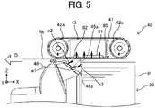
- FIG. 5 is an enlarged view of the suction belt unit 40 and the surrounding structure.
- the front blower 46 includes a levitation nozzle 46a and a separation nozzle 46b.
- the levitation nozzle 46a ejects levitation air a1 to levitate the sheet P
- the separation nozzle 46b ejects separation air a2 to separate the top sheet P and the second and subsequent sheets P under the top sheet P.
- the downward suction nozzle 45a is provided to generate downward suction air a3 so as to suck air in the vicinity of the front end of the upper portion of the bundle of sheets P downward.
- the downward suction nozzle 45a is coupled to a downward suction device.
- a suction port of a lower wall (exterior wall) 80 of the duct 43 includes a suction opening 81 facing the leading end of the bundle of sheets P from above, and a conveyance opening 82 facing a sheet conveyance path Rb downstream from the bundle of sheets P in the conveyance direction by the suction belt 41 (see FIG. 8 ).
- FIG. 6 is an enlarged view of the suction belt unit 40 and the surrounding structure with the front fence 36 removed, as viewed from the sheet feeding tray 30.
- the suction belt 41 is divided into three belts 41a, 41b, and 41c in the width direction of the suction belt 41, which is the same as the width direction of the sheet P.
- the separation nozzles 46b face the belt 41b disposed at the center portion corresponding to the center in the width direction of the sheet P.
- the levitation nozzles 46a are disposed corresponding to both end sides of the sheet P in the width direction, and the two of the levitation nozzles 46a face the belts 41a and 41c disposed on both sides.
- the downward suction nozzles 45a face the belts 41a and 41c disposed on both sides corresponding to both end sides of the sheet P in the width direction.
- the restrictor 34 (see FIG. 3 ) is disposed facing the downward suction nozzle 45a.
- FIG. 7 is a perspective view of the suction belt unit 40 as viewed obliquely from below.
- FIG. 8 is a perspective view of the suction belt unit 40 with the suction belt 41 depicted transparently so that the lower wall 80 of the duct 43 can be seen.
- a plurality of suction openings 81 faces each of the belts 41a, 41b, and 41c.
- the one conveyance opening 82 faces each of the belts 41a and 41c disposed on both sides.
- the plurality of suction ports (through holes) is omitted in the portion of the suction belt 41 wound around the roller 42a.
- FIG. 9 is a perspective view of the duct 43 whose lower wall 80 is viewed from below.
- the four suction openings 81 face each of the belts 41a, 41b, and 41c.
- the suction openings 81 and the conveyance openings 82 in the lower wall 80 are disposed at the same position in the duct 43 according to both the present embodiment and a comparative example described below.
- the phantom line (dashed double-dotted line) indicates the sheet P on the bundle of sheets P, and arrow D indicates the conveyance direction by the suction belt 41.
- the suction opening may be a single large hole but, in the present embodiment, is divided to the plurality of suction openings 81 with ribs to prevent the sheet P from deforming due to suction force, and to contact the sheet P with the surface of the suction belt 41 uniformly while the sheet P is sucked.
- the conveyance openings 82 are provided so as to prevent the sheet P from hanging down from the surface of the suction belt 41 when the trailing end of the sheet P passes through the suction openings 81 during conveyance of the sheet P, and to convey the sheet P while sucking the sheet P firmly.
- FIG. 10 is a perspective view of the duct 43 according to the comparative example.
- the duct 43 is rotated by 180 degrees from the state illustrated in FIG. 9 around the center line in the longitudinal direction so that the inner surface of the lower wall 80 of the duct 43 can be seen.
- An upper wall that is secured to screw holes 80a with screws is removed in FIG. 10 .
- Long side walls 83a and 83b and short side walls 84F and 84R are disposed on the four sides of the periphery of the lower wall 80.
- the lower wall 80, the side walls 83a, 83b, 84F, and 84R, and the upper wall form an internal space having a rectangular parallelepiped shape.
- An exhaust port 43a which is a coupling portion to connect the interior and the outside of the duct 43, is disposed on the short side wall 84R located on the rear side of the sheet feeding device 3.
- the width between the long side walls 83a and 83b is narrowed toward both ends of the exhaust port 43a in the vicinity of the exhaust port 43a.
- the internal space has a tapered shape in the vicinity of the exhaust port 43a.
- FIGS. 11A to 11C are diagrams of airflow in the duct 43 according to the comparative example.
- the velocity of the airflow at various points by computer simulation is indicated by arrows.
- Flow line 1 indicated by grey arrows means velocity slower than flow line 2 indicated by black arrows.
- FIG. 11A illustrates the airflow seen in the direction perpendicular to the lower wall 80
- FIG. 11B illustrates the airflow seen in the direction perpendicular to the long side wall 83b.
- the suction openings 81 and the conveyance openings 82 are not covered with the sheet P.
- FIG. 11C illustrates the airflow seen in the direction perpendicular to the lower wall 80 when all of the suction openings 81 are covered with the sheet P and the conveyance openings 82 are not covered with the sheet P.
- air flowing through the suction openings 81 and the conveyance openings 82 flows toward the exhaust port 43a disposed at one end of the duct 43.
- the air that has flowed into the duct 43 from the suction openings 81 and the conveyance openings 82 spreads randomly into the internal space of the duct 43.
- the air flows uniformly toward the exhaust port 43a, but the backflow of the air (vortex) is generated because the air flows into a place where air density is low.
- a part of the air flows toward the side opposite the exhaust port 43a.
- the vortex of the air interferes with the sucked air.
- an airflow in the direction in which air is ejected from the suction opening 81 is also generated as illustrated in area C in FIG. 11B .
- the conveyance openings 82 remain open, and an airflow as illustrated in FIG. 11C is generated. Air continues to flow into the duct 43 from the conveyance openings 82 after the suction openings 81 attract the sheet P. Due to this air, a vortex of the air is generated in the duct 43, and a part of the air flows in the direction to peel the attracted sheet P from the suction belt 41. Therefore, a minute gap may be formed between the sheet P and the surface of the suction belt 41. Accordingly, the sheet P may not be firmly attracted to the suction belt 41, and the sheet P may be accidentally forwarded a slight distance.
- the airflow in the duct 43 becomes faster at the position closer to the exhaust port 43a.
- Line L in FIG. 11B indicates a boundary line of a region where the air flows at the high velocity that is equivalent to the velocity inside the exhaust port 43a.
- the airflow that is as fast as the airflow in the exhaust port 43a is limited to the vicinity of the exhaust port 43a, and the airflow becomes faster in the suction opening 81 corresponding to the suction belt 41 closer to the exhaust port 43a (i.e., in the order of the suction belts 41c, 41b, and 41a in the present embodiment).
- the sheet P starts to be attracted on the side corresponding to the faster airflow sucking the sheet P.
- portions of the sheet P facing respective suction belts 41c, 41b, and 41a are sequentially attracted. The difference in the order to suck the portions of the sheet P may cause the sheet P to rotate and skew.
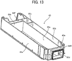
- FIG. 12 is a perspective view of the duct 43 whose inner surface of the lower wall 80 can be seen according to the present embodiment.
- FIG. 13 is a perspective view of the duct 43 as viewed from a different angle.
- the duct 43 includes a partition 85a as a first rectifier extending in the width direction perpendicular to the conveyance direction by the suction belt 41.
- the partition 85a partitions the internal space in the duct 43 into an upstream compartment where the suction openings 81 are disposed and a downstream compartment where the conveyance openings 82 are disposed in the conveyance direction.
- a short side wall 85b is disposed at the position aligned with the edge of the suction opening 81 to partition the upstream compartment into a side where the exhaust port 43a is disposed and another side opposite the exhaust port 43a.
- a short side wall 85c is disposed at the position aligned with the edge of the conveyance opening 82 to partition the downstream compartment into a side where the exhaust port 43a is disposed and another side opposite the exhaust port 43a.
- the internal space is completely separated into the upstream compartment where the suction openings 81 are disposed and the downstream compartment where the conveyance openings 82 are disposed. Therefore, when the suction opening 81 is covered, the air that has flowed into the downstream compartment through the conveyance openings 82 is prevented from entering the upstream compartment where the suction openings 81 are disposed. As a result, a vortex of the air is not generated.
- FIGS. 14 to 16 are perspective views of a duct 43 according to a variation (i.e., a first variation).
- the duct 43 according to the first variation includes partitions 87 and 88 in the upstream compartment where the suction openings 81 are disposed.
- the partitions 87 and 88 partition the upstream compartment into three regions and reach the exhaust port 43a.
- the plurality of suction openings 81 is divided into three areas each having the four suction openings 81. With this configuration, air flows through three areas corresponding to the suction belts 41a, 41b, and 41c into the three regions of the upstream compartment, and the airflows in the three regions do not interfere with each other.
- the duct 43 further includes a partition 90 in the downstream compartment where the conveyance openings 82 are disposed.
- the partition 90 partitions the downstream compartment into two regions and reaches the exhaust port 43a. With this configuration, air flows through the two conveyance openings 82 into the two regions, and the airflows in the two regions do not interfere with each other.
- the partitions 87, 88, and 90 serves as second rectifiers as described later. As illustrated in FIG. 16 , the partitions 85a, 87, 88, and 90 extend to the exhaust port 43a, and ends 85d, 87c, 88c, and 90c of the partitions 85a, 87, 88, and 90 are located at the opening of the exhaust port 43a.
- the long side walls 83a and 83b are omitted except for the portions corresponding to the partitions 87, 88, and 90 added in the first variation so that the interior of the duct 43 can be seen.
- the portions corresponding to the added partitions 87, 88, and 90 are shaded with halftone dots for the sake of understanding the shape.
- an upper wall 86 of the duct 43 is integrally formed together with the side walls 85b and 85c.
- each of the two added partitions 87 and 88 includes a block-shaped portion and a flat plate portion.
- the block-shaped portion is disposed on the rib (i.e., a portion other than the suction openings 81) between the three areas each having the four suction openings 81 in the lower wall 80.
- the flat plate portion extends from the top of the block-shaped portion to the exhaust port 43a.
- An upper corner 87a and a lower corner 87b ranging between the block-shaped portion and the flat plate portion of the partition 87 have curvatures.
- corners 88a and 88b of the other partition 88 have curvatures.
- FIG. 14 each of the two added partitions 87 and 88 includes a block-shaped portion and a flat plate portion.
- the block-shaped portion is disposed on the rib (i.e., a portion other than the suction openings 81) between the three areas each having the four suction openings 81 in the lower wall 80.
- the flat plate portion extend
- a corner 86a ranging between the upper wall 86 and the side wall 85b has a curvature.
- the side wall 85b partitions the upstream compartment into the side where the exhaust port 43a is disposed and another side opposite the exhaust port 43a.
- the portions forming the corners 86a, 87b, and 88b serve as the second rectifiers to rectify the direction of airflow. Air that flows through the suction openings 81 collides with the corners 86a, 87b, and 88b and turns toward the exhaust port 43a disposed at the one end of the duct 43.
- the corners 86a, 87b, and 88b have the same shape including the curvature. Further, the corners 87a, 88a, along which the air turned by the corners 86a, 87b, and 88b flows, have the same shape including the curvature.
- the corners 87a and 88a also serves as the second rectifiers.
- the areas of the three areas each having the four suction openings 81 are equal to each other.
- the cross-sectional areas of the internal spaces in an imaginary plane parallel to the suction port in the three regions from the suction port to a lowest point of the corners 86a, 87a, 87b, 88a or 88b along the flat face of the block-shaped portion are equal to the areas of the three areas, respectively.
- the cross-sectional areas are equal to each other between the three regions.
- the distance between the inner surface of the lower wall 80 of the duct 43 and the flat plate portion of the partition 88 on the low side, the distance between the flat plate portion of the partition 88 and the flat plate portion of the partition 87 on the high side, and the distance between the flat plate portion of the partition 87 and the inner surface of the upper wall 86 are equal to each other.
- the added partition 90 includes a block-shaped portion and a flat plate portion.
- the block-shaped portion is disposed on the rib between the two conveyance openings 82.
- the flat plate portion extends from the top of the block-shaped portion to the exhaust port 43a.
- An upper corner 90a and a lower corner 90b ranging between the block-shaped portion and the flat plate portion of the partition 90 have curvatures.
- a corner 86b ranging between the upper wall 86 and the side wall 85c has a curvature.
- the side wall 85c partitions the downstream compartment into the side where the exhaust port 43a is disposed and another side opposite the exhaust port 43a. This curvature of the corner 86b is equal to the curvature of the corner 90b.
- a block portion 89 extends from the edge of the conveyance opening 82 illustrated on the left side in FIG. 15 to the exhaust port 43a.
- a corner 89a of the block portion 89 facing the corner 90b has the same curvature as the corner 90a.
- the distance between the upper surface of the block portion 89 and the lower surface of the flat plate portion of the partition 90 is equal to the distance between the upper surface of the block-shaped portion and the flat plate portion of the partition 90, and the lower surface of the upper wall 86.
- the portions forming the corners 86b and 90b serve as the second rectifiers to rectify the direction of airflow. Air that flows through the conveyance openings 82 collides with the corners 86b and 90b and turns toward the exhaust port 43a.
- the corners 90a, 89a, along which the air turned by the corners 86b and 90b flows, have the same shape including the curvature.
- the corners 90a and 89a also serves as the second rectifiers.
- the shapes including the curvature are the same each other, the loss factors of the airflows are the same. As a result, air that flows into the duct 43 flows at an almost uniform velocity in the duct 43. Since the cross-sectional areas and the distances perpendicular to the airflows in the respective regions are equal to each other, the velocities of the airflows are close to each other between the respective regions.
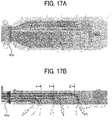
- FIGS. 17A and 17B are diagrams of airflow in the duct 43 according to the first variation.
- the velocity of the airflow at various points by computer simulation is indicated by arrows.
- FIG. 17A illustrates the airflow seen in the direction perpendicular to the lower wall 80
- FIG. 17B illustrates the airflow seen in the direction perpendicular to the long side wall 83b.
- the suction openings 81 and the conveyance openings 82 are not covered with the sheet P.
- the partition 85a partitions the internal space in the duct 43 into the upstream compartment where the suction openings 81 are disposed and the downstream compartment where the conveyance openings 82 are disposed.
- leader lines X, Y, and Z indicate boundaries of regions in which the airflow at substantially the same high velocity as in the exhaust port 43a is generated in the airflow path of the three regions between the exhaust port 43a and the three areas (i.e., the left, middle, and right areas in FIG. 17B ).
- the airflow at high velocity can be generated from the exhaust port 43a to the position facing each of the three areas in the horizontal direction in FIG. 17B .
- the inconvenience is prevented that portions of the sheet P facing respective suction belts 41c, 41b, and 41a are sequentially attracted.
- FIGS. 18 to 19 are perspective views of a duct 43 according to another variation (i.e., a second variation).
- FIG. 18 is a perspective view corresponding to FIG. 14 in the first variation
- FIG. 19 is a perspective view corresponding to FIG. 15 in the first variation.
- the second variation is the same as the first variation except that the flat plate portions of the partitions 87, 88, and 90 are shortened or eliminated.
- the partitions 87 and 88 are disposed in the upstream compartment where the suction openings 81 are disposed, and the flat plate portions of the partitions 87 and 88 does not reach the exhaust port 43a.
- the second partition 87 from the exhaust port 43a extends to the position above the edge of the book-shaped portion of the first partition 88 adjacent to the exhaust port 43a (the edge on the side opposite the exhaust port 43a).
- the flat plate portion of the first partition 88 has the same length as the flat plate portion of the second partition 87.
- the partition 90 is disposed in the downstream compartment where the conveyance openings 82 are disposed, and the flat plate portion of the partition 90 is eliminated except for a portion forming a corner ranging between the block-shaped portion and the flat plate portion.
- the second variation can also reduce the difference in airflow velocity between the three areas each having the four suction openings 81.
- FIGS. 20A and 20B are perspective views of a duct 43 according to yet another variation (i.e., a third variation).
- FIG. 20A is the perspective view corresponding to FIG. 14 in the first variation and FIG. 18 in the second variation.
- the flat plate portion of the second partition 87 in the second variation is extended.
- the position of the end portion 87c of the flat plate portion of the partition 87 matches the position Yo of the end portion 88c of the flat plate portion of the first partition 88 in the longitudinal direction of the duct 43.
- the partitions 87 and 88 are required to rectify the direction of airflow flowing through the suction port toward the exhaust port 43a. However, it is unnecessary that the positions of the end portions 87c and 88c completely aligned with the position Yo.
- the position of the end portion 87c can be any position from the edge of the block portion of the partition 88 on the opposite side of the exhaust port 43a toward the exhaust port 43a, but the partition 87 does not reach the exhaust port 43a unlike the partition 87 illustrated in FIG. 14 . That is, at least a part of the partition 87 overlaps with the partition 88 in the longitudinal direction of the duct 43.
- the shape of the end portions 87c and 88c (see FIG. 20A ) of the flat plate portions can be tapered as illustrated in FIG. 20B . Further, the end portions 87c and 88c can be rounded and have an arc shape. These shapes are applicable to other variations described above. These shapes make the airflow in the duct 43 smooth.
- the partitions 87, 88, and 90 are made of, for example, resin such as acrylonitrile butadiene styrene (ABS), polyoxymethylene (POM), or nylon, or metal such as molybdenum (Mo).
- the partitions 87, 88, and 90 are made of ABS, POM, or nylon
- surface layers may be formed on the surfaces of the partitions 87 and 88.
- the surface layer may be formed on inner surfaces of all walls (e.g., the upper wall 86, the lower wall 80, the side walls 83a, 83b, 85b, and 85c, and the partition 85a).
- the surfaces made of ABS, POM, or nylon can be coated with metal such as molybdenum or aluminum (Al) by plating treatment, and further, the surface of aluminum can be treated by alumite treatment, in order to smooth the surfaces and reduce air resistance while protecting the surfaces of the partitions 87, 88, and 90 and the walls.
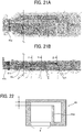
- the position Yo of each the end portion 87c and 88c in the longitudinal direction of the duct 43 is determined as follows.
- FIGS. 21A and 21B the position Yo of the end portions 87c and 88c is illustrated using the diagrams of airflow in FIGS. 17A and 17B .
- the velocity of the airflows that flow from the three areas each having the four suction openings 81 become constant at the position Yo on the side of the exhaust port 43a.
- the flat plate portions of the partition 87 and 88 do not exist from the position Yo to the exhaust port 43a. Therefore, the cross-section of the duct 43 through which air flows is effectively enlarged. As a result, the airflow is improved.
- the partition 85a between the upstream compartment where the suction openings 81 are disposed and the downstream compartment where the conveyance openings 82 are disposed completely partitions the internal space between the inner surface of the lower wall 80 and the lower surface of the upper wall 86 of the duct 43.
- the partition 85a can partially partition the internal space with a gap G as illustrated in FIG. 22 . That is, when the internal space is partially comparted, the effects described in the above embodiments can be obtained.
- Each part of the duct can be fabricated, for example, by three-dimensional (3D) printers.
- the duct can be manufactured by molding as a single piece or by assembling separated parts.
- the endless belt 41 has the through holes, but an endless belt without through holes can be used.
- the endless belt is arranged so as to expose the suction port of the duct.
- the belt conveyance device is not limited to the sheet feeding device 3, but can be applied to, for example, general belt devices using a suction belt, such as a sheet conveyance device.
Landscapes
- Engineering & Computer Science (AREA)
- Mechanical Engineering (AREA)
- Physics & Mathematics (AREA)
- General Physics & Mathematics (AREA)
- Sheets, Magazines, And Separation Thereof (AREA)
- Delivering By Means Of Belts And Rollers (AREA)
- Paper Feeding For Electrophotography (AREA)
Abstract
A belt conveyance device (40) includes an endless belt (41), a duct (43) having a suction port (81; 82), and a rectifier (85a) inside the duct (43). The duct (43) is surrounded by an inner circumferential surface of the endless belt (41). The rectifier (85a) extends in a width direction of the endless belt (41) perpendicular to a direction of conveyance by the endless belt (41).
Description
- Embodiments of the present disclosure relate to a belt conveyance device, a sheet feeding device, an image forming apparatus, and an image forming system.
- There is known a belt conveyance device that includes an endless belt having through holes and a duct having a suction port. The duct is disposed in a space surrounded by an inner circumferential surface of the endless belt.
- For example,
JP-2019-094212 - When this type of belt conveyance device is used for conveying a sheet, the suction efficiency of the duct is required to be improved in order to reliably convey various sheets having different weights or flexibilities, in particular, a sheet having heavy weight or low flexibility.
- To solve the above-described situation, an improved belt conveyance device includes an endless belt, a duct having a suction port, and a rectifier inside the duct. The duct is surrounded by an inner circumferential surface of the endless belt. The rectifier extends in a width direction of the endless belt perpendicular to a direction of conveyance by the endless belt.
- According to the present disclosure, suction efficiency of the duct can be improved.
- A more complete appreciation of the disclosure and many of the attendant advantages thereof will be readily obtained as the same becomes better understood by reference to the following detailed description when considered in connection with the accompanying drawings, wherein:
-
FIG. 1 is a schematic view illustrating a configuration of an image forming system according to an embodiment of the present disclosure; -
FIG. 2 is a schematic view illustrating a configuration of an electrophotographic image forming apparatus of the image forming system inFIG. 1 ; -
FIG. 3 is a schematic view illustrating a configuration of a sheet feeding device of the image forming system inFIG. 1 ; -
FIG. 4 is a schematic perspective view of the sheet feeding device inFIG. 3 ; -
FIG. 5 is an enlarged view of a suction belt unit of the sheet feeding device and the surrounding structure; -
FIG. 6 is an enlarged view of the suction belt unit of the sheet feeding device and the surrounding structure; -
FIG. 7 is a perspective view of the suction belt unit as viewed obliquely from below; -
FIG. 8 is a perspective view of the suction belt unit with a suction belt depicted transparently; -
FIG. 9 is a perspective view of a duct whose lower wall is viewed from below according to an embodiment of the present disclosure; -
FIG. 10 is a perspective view of a duct according to a comparative example; -
FIGS. 11A to 11C are diagrams of airflow in the duct according to the comparative example; -
FIG. 12 is a perspective view of the duct whose inner surface of the lower wall is viewed according to an embodiment of the present disclosure; -
FIG. 13 is a perspective view of the duct according to an embodiment of the present disclosure as viewed from a different angle; -
FIG. 14 is a perspective view of a duct according to a first variation; -
FIG. 15 is a perspective view of the duct according to the first variation as viewed from a different angle; -
FIG. 16 is a perspective view of the duct according to the first variation as viewed from another different angle; -
FIGS. 17A and 17B are diagrams of airflow in the duct according to the first variation; -
FIG. 18 is a perspective view of a duct according to a second variation; -
FIG. 19 is a perspective view of the duct according to the second variation as viewed from a different angle; -
FIGS. 20A and 20B are a perspective view of a duct according to a third variation; -
FIGS. 21A and 21B are diagrams of airflow illustrating a position Yo of an end portion of a partition of the duct according to the third variation; and -
FIG. 22 is a cross-sectional view of a duct according to another variation. - The accompanying drawings are intended to depict embodiments of the present disclosure and should not be interpreted to limit the scope thereof. The accompanying drawings are not to be considered as drawn to scale unless explicitly noted. In addition, identical or similar reference numerals designate identical or similar components throughout the several views.
- In describing embodiments illustrated in the drawings, specific terminology is employed for the sake of clarity. However, the disclosure of this patent specification is not intended to be limited to the specific terminology so selected, and it is to be understood that each specific element includes all technical equivalents that have the same function, operate in a similar manner, and achieve a similar result.
- As used herein, the singular forms "a", "an", and "the" are intended to include the plural forms as well, unless the context clearly indicates otherwise.
- It is to be noted that the suffixes Y, M, C, and Bk attached to each reference numeral indicate only that components indicated thereby are used for forming yellow, magenta, cyan, and black images, respectively, and hereinafter may be omitted when color discrimination is not necessary.
- A description is given below of a sheet feeding device according to an embodiment of the present disclosure.
FIG. 1 is a schematic view illustrating a configuration of animage forming system 1 according to the present embodiment. Theimage forming system 1 includes animage forming apparatus 2 to form an image on a sheet and asheet feeding device 3 to feed the sheet to theimage forming apparatus 2. Thesheet feeding device 3 is disposed on the side of theimage forming apparatus 2. Alternatively, theimage forming apparatus 2 may include thesheet feeding device 3 in one united body. - The
sheet feeding device 3 according to the present embodiment is applicable to an image forming apparatus employing an electrophotographic method or an inkjet method. As an example, the overall configuration and operation of the electrophotographicimage forming apparatus 2 are described.FIG. 2 is a schematic view illustrating a configuration of the electrophotographicimage forming apparatus 2. Theimage forming apparatus 2 includes fourprocess units process units - Each of the
process units photoconductor 5 as an electrostatic latent image bearer, acharging roller 6 as a charging device to charge the surface of thephotoconductor 5, a developingdevice 7 to form a toner image on the surface of thephotoconductor 5, and acleaning blade 8 as a cleaning device to clean the surface of thephotoconductor 5. - An
exposure device 9 is disposed above theprocess units exposure device 9 irradiates thephotoconductors 5 of theprocess units transfer device 10 is disposed below theprocess units transfer device 10 includes anintermediate transfer belt 15 looped aroundmultiple rollers 11 to 14. Theintermediate transfer belt 15 is an endless belt. Theintermediate transfer belt 15 rotates in the direction indicated by arrow A1 illustrated inFIG. 2 as a drive roller, which is one of themultiple rollers 11 to 14, rotates. - Four
primary transfer rollers 16 are disposed opposite the respective fourphotoconductors 5. Eachprimary transfer roller 16 is pressed against the correspondingphotoconductor 5 via theintermediate transfer belt 15, and a nip between theintermediate transfer belt 15 and thephotoconductor 5 is called a primary transfer nip. Asecondary transfer roller 17 is disposed opposite theroller 14, which is one of themultiple rollers 11 to 14 around which theintermediate transfer belt 15 is looped. The contact portion between thesecondary transfer roller 17 and theintermediate transfer belt 15 is called a secondary transfer nip. - A conveyance path Ra is disposed inside the
image forming apparatus 2, and a sheet is supplied from thesheet feeding device 3 described above to the secondary transfer nip and guided to anoutput tray 18 disposed outside the apparatus body of theimage forming apparatus 2 along the conveyance path Ra. Along the conveyance path Ra, aregistration roller pair 19 is disposed upstream from thesecondary transfer roller 17 in a direction of conveyance of the sheet indicated by arrow D inFIG. 2 (hereinafter referred to as a conveyance direction). A fixingdevice 20 is disposed downstream from thesecondary transfer roller 17 in the conveyance direction. Anoutput roller pair 21 is disposed downstream from the fixingdevice 20 in the conveyance direction. The fixingdevice 20 includes aheating roller 20a including a heat source therein and apressure roller 20b that presses theheating roller 20a. Theheating roller 20a and thepressure roller 20b are pressed against each other, and a contact portion between theheating roller 20a and thepressure roller 20b is called a fixing nip. - The basic operation of the
image forming apparatus 2 is as follows. As eachphotoconductor 5 of theprocess units FIG. 2 , the chargingroller 6 uniformly charges the surface of thephotoconductor 5 in a predetermined polarity. Then, theexposure device 9 irradiates the charged surfaces of therespective photoconductors 5 with laser beams based on image data of documents read by a reading device. Thus, electrostatic latent images are formed on the surfaces of therespective photoconductors 5. Note that the image data for exposing thephotoconductor 5 is single-color image data obtained by decomposing a desired full-color image into individual color components, that is, yellow, cyan, magenta, and black components. The electrostatic latent image thus formed on thephotoconductor 5 is developed into a toner image (visible image) with toner deposited by the developingdevice 7. - The
intermediate transfer belt 15 rotates in the direction indicated by arrow A1 illustrated inFIG. 2 as the drive roller rotates, which is one of themultiple rollers 11 to 14 around which theintermediate transfer belt 15 is looped. A power supply applies a constant voltage or a voltage controlled at a constant current, which has a polarity opposite the polarity of the charged toner, to theprimary transfer rollers 16. As a result, transfer electric fields are generated at the respective primary transfer nips between theprimary transfer rollers 16 and thephotoconductors 5. The transfer electric fields generated at the primary transfer nips sequentially transfer and superimpose the respective toner images from thephotoconductors 5 onto theintermediate transfer belt 15. Thus, a full-color toner image is formed on the surface of theintermediate transfer belt 15. After the primary transfer process, a certain amount of toner, which is not transferred to theintermediate transfer belt 15, remains on the surface of thephotoconductor 5. Thecleaning blade 8 removes the toner remaining onphotoconductors 5. - The
sheet feeding device 3 illustrated inFIG. 1 feeds the sheet to theimage forming apparatus 2. Aregistration roller pair 19 forwards the sheet fed from thesheet feeding device 3 to the secondary transfer nip between thesecondary transfer roller 17 and theintermediate transfer belt 15 at an appropriate timing. At that time, a transfer voltage opposite in polarity to the toner image on theintermediate transfer belt 15 is applied to thesecondary transfer roller 17, and a transfer electric field is generated in the secondary transfer nip. The transfer electric field generated in the secondary transfer nip collectively transfers the toner images from theintermediate transfer belt 15 onto the sheet. - The sheet bearing the toner image is conveyed to the fixing
device 20. In the fixingdevice 20, the sheet is sandwiched between theheating roller 20a and thepressure roller 20b, thereby fixing the toner image on the sheet under heat and pressure. Then, theoutput roller pair 21 ejects the sheet to theoutput tray 18. - The above description concerns the image forming operation of the color
image forming apparatus 2 to form the full-color toner image on the sheet. Alternatively, theimage forming apparatus 2 may form a monochrome toner image by using any one of the fourprocess units process units -
FIG. 3 is a schematic view illustrating a configuration of thesheet feeding device 3 according to the present embodiment.FIG. 4 is a schematic perspective view of thesheet feeding device 3. Thesheet feeding device 3 includes asheet feeding tray 30 and asuction belt unit 40. Thesheet feeding tray 30 serves as a sheet stacker on which a plurality of sheets P can be stacked. Thesuction belt unit 40 serves as a conveyor or a belt conveyance device to feed and convey the sheet P. It is to be noted that the "sheet P" used here includes thick paper, post cards, envelopes, plain paper, thin paper, coated paper, art paper, tracing paper, and the like. Additionally, overhead projector (OHP) transparencies (OHP sheet or OHP film) can be used as a sheet-shaped recording medium. - The
sheet feeding tray 30 includes abottom plate 31, afront fence 36, a pair of side fences 32 (seeFIG. 4 ), and anend fence 33. Thefront fence 36 positions the leading end of the bundle of sheets P stacked on thebottom plate 31 in the conveyance direction of the sheet P. The pair ofside fences 32 positions both ends of the bundle of sheets P in the width direction of the sheet P. Theend fence 33 positions the trailing end of the bundle of sheets P in the conveyance direction. A restrictor 34 is disposed at the upper end of thefront fence 36 to inhibit the sheets P other than the top sheet P (the second and subsequent sheets P from the top) from moving in the conveyance direction. The restrictor 34 is arranged so as to project above the uppermost position of the bundle of sheets P stacked in thesheet feeding tray 30. A pressingmember 35 projecting from theend fence 33 toward the stacked sheets P is disposed at the upper portion of theend fence 33. - The
suction belt unit 40 is disposed above the sheets P stacked in thesheet feeding tray 30. Thesuction belt unit 40 includes asuction belt 41 that is an endless belt having through holes. Thesuction belt 41 is provided with a plurality of suction ports (i.e., the through holes). Aduct 43 having a suction port is surrounded by the inner circumferential surface of thesuction belt 41. Air is sucked from the suction port of theduct 43 via the plurality of suction ports of thesuction belt 41 to attract the sheet P on the lower surface of thesuction belt 41. Thesuction belt 41 is stretched around a plurality ofrollers rollers suction belt 41 rotates in the direction indicated by arrow A2 inFIG. 3 . Aconveyance roller pair 50 is disposed downstream from thesuction belt 41 to convey the sheet P, and asheet sensor 60 is disposed downstream from theconveyance roller pair 50 to detect the sheet P conveyed by theconveyance roller pair 50 in the conveyance direction indicated by arrow D. - An
upper position detector 70 is disposed above thesheet feeding tray 30 to detect the position of the upper surface of the bundle of sheets P stacked in thesheet feeding tray 30. Theupper position detector 70 includes anactuator 71 and aswing sensor 72. The actuator 71 contacts the upper surface of the bundle of sheets P and is swingable according to the position of the upper surface. Theswing sensor 72 detects the swing of theactuator 71. The sheet P is supplied from the bundle of sheets P, and theactuator 71 swings as the height of the bundle of sheets P decreases. Theswing sensor 72 detects the amount of swing of theactuator 71, and the push-up device raises thebottom plate 31 of thesheet feeding tray 30 based on the detection signal from theswing sensor 72. Thus, the height (distance) h from the upper surface of the bundle of sheets P to thesuction belt 41 is kept constant. - A
front blower 46 is disposed in front of thesheet feeding tray 30 in the conveyance direction to blow air onto the sheet P stacked in thesheet feeding tray 30. Theside fence 32 is provided withair outlets FIG. 4 ). -
FIG. 5 is an enlarged view of thesuction belt unit 40 and the surrounding structure. Thefront blower 46 includes alevitation nozzle 46a and aseparation nozzle 46b. Thelevitation nozzle 46a ejects levitation air a1 to levitate the sheet P, and theseparation nozzle 46b ejects separation air a2 to separate the top sheet P and the second and subsequent sheets P under the top sheet P. Thedownward suction nozzle 45a is provided to generate downward suction air a3 so as to suck air in the vicinity of the front end of the upper portion of the bundle of sheets P downward. Thedownward suction nozzle 45a is coupled to a downward suction device. - As illustrated in
FIG. 5 , a suction port of a lower wall (exterior wall) 80 of theduct 43 includes asuction opening 81 facing the leading end of the bundle of sheets P from above, and aconveyance opening 82 facing a sheet conveyance path Rb downstream from the bundle of sheets P in the conveyance direction by the suction belt 41 (seeFIG. 8 ). -
FIG. 6 is an enlarged view of thesuction belt unit 40 and the surrounding structure with thefront fence 36 removed, as viewed from thesheet feeding tray 30. In the example illustrated inFIG. 6 , thesuction belt 41 is divided into threebelts suction belt 41, which is the same as the width direction of the sheet P. The separation nozzles 46b face thebelt 41b disposed at the center portion corresponding to the center in the width direction of the sheet P. The levitation nozzles 46a are disposed corresponding to both end sides of the sheet P in the width direction, and the two of thelevitation nozzles 46a face thebelts downward suction nozzles 45a face thebelts FIG. 3 ) is disposed facing thedownward suction nozzle 45a. -
FIG. 7 is a perspective view of thesuction belt unit 40 as viewed obliquely from below.FIG. 8 is a perspective view of thesuction belt unit 40 with thesuction belt 41 depicted transparently so that thelower wall 80 of theduct 43 can be seen. A plurality ofsuction openings 81 faces each of thebelts conveyance opening 82 faces each of thebelts FIGS. 7 and8 , the plurality of suction ports (through holes) is omitted in the portion of thesuction belt 41 wound around theroller 42a. -
FIG. 9 is a perspective view of theduct 43 whoselower wall 80 is viewed from below. In the example illustrated inFIG. 9 , the foursuction openings 81 face each of thebelts suction openings 81 and theconveyance openings 82 in thelower wall 80 are disposed at the same position in theduct 43 according to both the present embodiment and a comparative example described below. The phantom line (dashed double-dotted line) indicates the sheet P on the bundle of sheets P, and arrow D indicates the conveyance direction by thesuction belt 41. - The suction opening may be a single large hole but, in the present embodiment, is divided to the plurality of
suction openings 81 with ribs to prevent the sheet P from deforming due to suction force, and to contact the sheet P with the surface of thesuction belt 41 uniformly while the sheet P is sucked. Theconveyance openings 82 are provided so as to prevent the sheet P from hanging down from the surface of thesuction belt 41 when the trailing end of the sheet P passes through thesuction openings 81 during conveyance of the sheet P, and to convey the sheet P while sucking the sheet P firmly. -
FIG. 10 is a perspective view of theduct 43 according to the comparative example. InFIG. 10 , theduct 43 is rotated by 180 degrees from the state illustrated inFIG. 9 around the center line in the longitudinal direction so that the inner surface of thelower wall 80 of theduct 43 can be seen. An upper wall that is secured to screwholes 80a with screws is removed inFIG. 10 .Long side walls short side walls lower wall 80. Thelower wall 80, theside walls exhaust port 43a, which is a coupling portion to connect the interior and the outside of theduct 43, is disposed on theshort side wall 84R located on the rear side of thesheet feeding device 3. The width between thelong side walls exhaust port 43a in the vicinity of theexhaust port 43a. As a result, the internal space has a tapered shape in the vicinity of theexhaust port 43a. -
FIGS. 11A to 11C are diagrams of airflow in theduct 43 according to the comparative example. The velocity of the airflow at various points by computer simulation is indicated by arrows.Flow line 1 indicated by grey arrows means velocity slower thanflow line 2 indicated by black arrows.FIG. 11A illustrates the airflow seen in the direction perpendicular to thelower wall 80, andFIG. 11B illustrates the airflow seen in the direction perpendicular to thelong side wall 83b. In bothFIGS. 11A and 11B , thesuction openings 81 and theconveyance openings 82 are not covered with the sheet P.FIG. 11C illustrates the airflow seen in the direction perpendicular to thelower wall 80 when all of thesuction openings 81 are covered with the sheet P and theconveyance openings 82 are not covered with the sheet P. - As illustrates in
FIGS. 11A and 11B , air flowing through thesuction openings 81 and theconveyance openings 82 flows toward theexhaust port 43a disposed at one end of theduct 43. The air that has flowed into theduct 43 from thesuction openings 81 and theconveyance openings 82 spreads randomly into the internal space of theduct 43. Preferably, the air flows uniformly toward theexhaust port 43a, but the backflow of the air (vortex) is generated because the air flows into a place where air density is low. For example, in area A inFIG. 11A and area B inFIG. 11B , a part of the air flows toward the side opposite theexhaust port 43a. Thus, the vortex of the air interferes with the sucked air. As a result, an airflow in the direction in which air is ejected from thesuction opening 81 is also generated as illustrated in area C inFIG. 11B . - Further, when the top sheet P of the bundle of sheets P is attracted to the
suction belt 41 as illustrated inFIG. 3 , theconveyance openings 82 remain open, and an airflow as illustrated inFIG. 11C is generated. Air continues to flow into theduct 43 from theconveyance openings 82 after thesuction openings 81 attract the sheet P. Due to this air, a vortex of the air is generated in theduct 43, and a part of the air flows in the direction to peel the attracted sheet P from thesuction belt 41. Therefore, a minute gap may be formed between the sheet P and the surface of thesuction belt 41. Accordingly, the sheet P may not be firmly attracted to thesuction belt 41, and the sheet P may be accidentally forwarded a slight distance. - Further, as illustrated in
FIG. 11B , the airflow in theduct 43 becomes faster at the position closer to theexhaust port 43a. Line L inFIG. 11B indicates a boundary line of a region where the air flows at the high velocity that is equivalent to the velocity inside theexhaust port 43a. As described above, the airflow that is as fast as the airflow in theexhaust port 43a is limited to the vicinity of theexhaust port 43a, and the airflow becomes faster in thesuction opening 81 corresponding to thesuction belt 41 closer to theexhaust port 43a (i.e., in the order of thesuction belts respective suction belts - Therefore, among the various inconveniences described above, in order to eliminate the inconvenience that occurs when the
suction openings 81 are covered, theduct 43 according to the present embodiment prevents the air that has flowed in through theconveyance openings 82 from flowing into the portion of theduct 43 on the side where thesuction openings 81 are disposed.FIG. 12 is a perspective view of theduct 43 whose inner surface of thelower wall 80 can be seen according to the present embodiment.FIG. 13 is a perspective view of theduct 43 as viewed from a different angle. Theduct 43 includes apartition 85a as a first rectifier extending in the width direction perpendicular to the conveyance direction by thesuction belt 41. Thepartition 85a partitions the internal space in theduct 43 into an upstream compartment where thesuction openings 81 are disposed and a downstream compartment where theconveyance openings 82 are disposed in the conveyance direction. - Further, in the example illustrated in
FIGS. 12 and13 , ashort side wall 85b is disposed at the position aligned with the edge of thesuction opening 81 to partition the upstream compartment into a side where theexhaust port 43a is disposed and another side opposite theexhaust port 43a. Similarly, ashort side wall 85c is disposed at the position aligned with the edge of theconveyance opening 82 to partition the downstream compartment into a side where theexhaust port 43a is disposed and another side opposite theexhaust port 43a. These configurations narrows a space where turbulence may occur. - In the
duct 43 according to the present embodiment, the internal space is completely separated into the upstream compartment where thesuction openings 81 are disposed and the downstream compartment where theconveyance openings 82 are disposed. Therefore, when thesuction opening 81 is covered, the air that has flowed into the downstream compartment through theconveyance openings 82 is prevented from entering the upstream compartment where thesuction openings 81 are disposed. As a result, a vortex of the air is not generated. -
FIGS. 14 to 16 are perspective views of aduct 43 according to a variation (i.e., a first variation). In addition to thepartition 85a, theduct 43 according to the first variation includespartitions suction openings 81 are disposed. Thepartitions exhaust port 43a. The plurality ofsuction openings 81 is divided into three areas each having the foursuction openings 81. With this configuration, air flows through three areas corresponding to thesuction belts duct 43 further includes apartition 90 in the downstream compartment where theconveyance openings 82 are disposed. Thepartition 90 partitions the downstream compartment into two regions and reaches theexhaust port 43a. With this configuration, air flows through the twoconveyance openings 82 into the two regions, and the airflows in the two regions do not interfere with each other. Thepartitions FIG. 16 , thepartitions exhaust port 43a, and ends 85d, 87c, 88c, and 90c of thepartitions exhaust port 43a. - In
FIGS. 14 to 16 , thelong side walls partitions duct 43 can be seen. The portions corresponding to the addedpartitions FIGS. 14 to 16 , anupper wall 86 of theduct 43 is integrally formed together with theside walls - In
FIG. 14 , each of the two addedpartitions suction openings 81 in thelower wall 80. The flat plate portion extends from the top of the block-shaped portion to theexhaust port 43a. Anupper corner 87a and alower corner 87b ranging between the block-shaped portion and the flat plate portion of thepartition 87 have curvatures. Similarly,corners other partition 88 have curvatures. In addition, inFIG. 14 , acorner 86a ranging between theupper wall 86 and theside wall 85b has a curvature. As described above, theside wall 85b partitions the upstream compartment into the side where theexhaust port 43a is disposed and another side opposite theexhaust port 43a. - The portions forming the
corners suction openings 81 collides with thecorners exhaust port 43a disposed at the one end of theduct 43. Thecorners corners corners corners - Further, the areas of the three areas each having the four
suction openings 81 are equal to each other. The cross-sectional areas of the internal spaces in an imaginary plane parallel to the suction port in the three regions from the suction port to a lowest point of thecorners lower wall 80 of theduct 43 and the flat plate portion of thepartition 88 on the low side, the distance between the flat plate portion of thepartition 88 and the flat plate portion of thepartition 87 on the high side, and the distance between the flat plate portion of thepartition 87 and the inner surface of theupper wall 86 are equal to each other. - In
FIG. 15 , the addedpartition 90 includes a block-shaped portion and a flat plate portion. The block-shaped portion is disposed on the rib between the twoconveyance openings 82. The flat plate portion extends from the top of the block-shaped portion to theexhaust port 43a. Anupper corner 90a and alower corner 90b ranging between the block-shaped portion and the flat plate portion of thepartition 90 have curvatures. In addition, inFIG. 15 , acorner 86b ranging between theupper wall 86 and theside wall 85c has a curvature. As described above, theside wall 85c partitions the downstream compartment into the side where theexhaust port 43a is disposed and another side opposite theexhaust port 43a. This curvature of thecorner 86b is equal to the curvature of thecorner 90b. - Further, a
block portion 89 extends from the edge of theconveyance opening 82 illustrated on the left side inFIG. 15 to theexhaust port 43a. Acorner 89a of theblock portion 89 facing thecorner 90b has the same curvature as thecorner 90a. The distance between the upper surface of theblock portion 89 and the lower surface of the flat plate portion of thepartition 90 is equal to the distance between the upper surface of the block-shaped portion and the flat plate portion of thepartition 90, and the lower surface of theupper wall 86. The portions forming thecorners conveyance openings 82 collides with thecorners exhaust port 43a. Thecorners corners corners - According to the first variation, air flows through the three areas each having the four
suction openings 81 into the three regions, and the airflows in the three regions do not interfere with each other from thesuction openings 81 to theexhaust port 43a. Further, air flows through the twoconveyance openings 82 into the two regions, and the airflows in the two regions do not interfere with each other from theconveyance openings 82 to theexhaust port 43a. Therefore, turbulence due to the interference of the airflows does not occur. In addition, since the airflow does not become faster at the position closer to theexhaust port 43a, the inconvenience is prevented that portions of the sheet P facingrespective suction belts duct 43 flows at an almost uniform velocity in theduct 43. Since the cross-sectional areas and the distances perpendicular to the airflows in the respective regions are equal to each other, the velocities of the airflows are close to each other between the respective regions. -
FIGS. 17A and 17B are diagrams of airflow in theduct 43 according to the first variation. The velocity of the airflow at various points by computer simulation is indicated by arrows.FIG. 17A illustrates the airflow seen in the direction perpendicular to thelower wall 80, andFIG. 17B illustrates the airflow seen in the direction perpendicular to thelong side wall 83b. In bothFIG. 17A and 17B , thesuction openings 81 and theconveyance openings 82 are not covered with the sheet P. As compared withFIG. 11A , inFIG. 17A , thepartition 85a partitions the internal space in theduct 43 into the upstream compartment where thesuction openings 81 are disposed and the downstream compartment where theconveyance openings 82 are disposed. Accordingly, air does not flow across the upstream compartment and the downstream compartment. Therefore, when the sheet P has been attracted to thesuction belt 41 and only thesuction openings 81 are covered with the sheet P, air flows into the downstream compartment through theconveyance openings 82. However, the airflow in the downstream compartment does not affect the airflow in the upstream compartment where thesuction openings 81 are disposed. - Moreover, as illustrated in
FIG. 17B , since the interference of the airflows between the three regions corresponding the three areas each having the foursuction openings 81 is prevented, air flows at the same velocity in thesuction openings 81 of each of the three areas. Leader lines X, Y, and Z indicate boundaries of regions in which the airflow at substantially the same high velocity as in theexhaust port 43a is generated in the airflow path of the three regions between theexhaust port 43a and the three areas (i.e., the left, middle, and right areas inFIG. 17B ). Thus, the airflow at high velocity can be generated from theexhaust port 43a to the position facing each of the three areas in the horizontal direction inFIG. 17B . As a result, the inconvenience is prevented that portions of the sheet P facingrespective suction belts -
FIGS. 18 to 19 are perspective views of aduct 43 according to another variation (i.e., a second variation).FIG. 18 is a perspective view corresponding toFIG. 14 in the first variation, andFIG. 19 is a perspective view corresponding toFIG. 15 in the first variation. The second variation is the same as the first variation except that the flat plate portions of thepartitions - In
FIG. 18 , thepartitions suction openings 81 are disposed, and the flat plate portions of thepartitions exhaust port 43a. Specifically, thesecond partition 87 from theexhaust port 43a extends to the position above the edge of the book-shaped portion of thefirst partition 88 adjacent to theexhaust port 43a (the edge on the side opposite theexhaust port 43a). The flat plate portion of thefirst partition 88 has the same length as the flat plate portion of thesecond partition 87. - In
FIG. 19 , thepartition 90 is disposed in the downstream compartment where theconveyance openings 82 are disposed, and the flat plate portion of thepartition 90 is eliminated except for a portion forming a corner ranging between the block-shaped portion and the flat plate portion. The second variation can also reduce the difference in airflow velocity between the three areas each having the foursuction openings 81. -
FIGS. 20A and 20B are perspective views of aduct 43 according to yet another variation (i.e., a third variation).FIG. 20A is the perspective view corresponding toFIG. 14 in the first variation andFIG. 18 in the second variation. In the third variation, the flat plate portion of thesecond partition 87 in the second variation is extended. The position of theend portion 87c of the flat plate portion of thepartition 87 matches the position Yo of theend portion 88c of the flat plate portion of thefirst partition 88 in the longitudinal direction of theduct 43. - Note that the
partitions exhaust port 43a. However, it is unnecessary that the positions of theend portions end portion 87c can be any position from the edge of the block portion of thepartition 88 on the opposite side of theexhaust port 43a toward theexhaust port 43a, but thepartition 87 does not reach theexhaust port 43a unlike thepartition 87 illustrated inFIG. 14 . That is, at least a part of thepartition 87 overlaps with thepartition 88 in the longitudinal direction of theduct 43. - In the
partitions end portions FIG. 20A ) of the flat plate portions can be tapered as illustrated inFIG. 20B . Further, theend portions duct 43 smooth. Thepartitions partitions partitions partitions upper wall 86, thelower wall 80, theside walls partition 85a). The surfaces made of ABS, POM, or nylon can be coated with metal such as molybdenum or aluminum (Al) by plating treatment, and further, the surface of aluminum can be treated by alumite treatment, in order to smooth the surfaces and reduce air resistance while protecting the surfaces of thepartitions - The position Yo of each the
end portion duct 43 is determined as follows. InFIGS. 21A and 21B , the position Yo of theend portions FIGS. 17A and 17B . The velocity of the airflows that flow from the three areas each having the foursuction openings 81 become constant at the position Yo on the side of theexhaust port 43a. The flat plate portions of thepartition exhaust port 43a. Therefore, the cross-section of theduct 43 through which air flows is effectively enlarged. As a result, the airflow is improved. - In the above-described embodiments, the
partition 85a between the upstream compartment where thesuction openings 81 are disposed and the downstream compartment where theconveyance openings 82 are disposed completely partitions the internal space between the inner surface of thelower wall 80 and the lower surface of theupper wall 86 of theduct 43. Alternatively, thepartition 85a can partially partition the internal space with a gap G as illustrated inFIG. 22 . That is, when the internal space is partially comparted, the effects described in the above embodiments can be obtained. - According to the above-described embodiments, the following effects can be obtained.
- 1. Since airflows for sucking the sheet and for conveying the sheet is separated, the respective airflows do not interfere with each other, thereby improving the performance of conveying or feeding the sheet.
- 2. Since airflow in the duct is uniform, the airflow without loss of velocity can be provided.
- 3. Since portions of the duct into which air flows have the same shape, the loss factor of the airflow in the duct can be the same, thereby uniforming the airflow.
- Above-described effects lead to the following advantages. That is, the suction force is increased, and thick paper, heavy paper can be conveyed or fed. Further, sheets other than paper, such as film, plastic, and sheet metal, can be conveyed or fed. Further, since the air flowing into the duct through the suction port is uniform, skew of the sheet can be prevented, thereby conveying the sheet with high accuracy.
- Each part of the duct can be fabricated, for example, by three-dimensional (3D) printers. The duct can be manufactured by molding as a single piece or by assembling separated parts.
- Above-described embodiments are examples. In the above-described embodiments, the
endless belt 41 has the through holes, but an endless belt without through holes can be used. In this case, the endless belt is arranged so as to expose the suction port of the duct. Further, the belt conveyance device is not limited to thesheet feeding device 3, but can be applied to, for example, general belt devices using a suction belt, such as a sheet conveyance device.
Claims (13)
- A belt conveyance device (40) comprising:an endless belt (41);a duct (43) having a suction port (81; 82), the duct (43) surrounded by an inner circumferential surface of the endless belt (41); anda rectifier (85a) inside the duct, extending in a width direction of the endless belt (41) perpendicular to a direction of conveyance by the endless belt (41).
- The belt conveyance device (40) according to claim 1,
wherein the rectifier (85a) partitions an internal space in the duct (43) into an upstream compartment and a downstream compartment in the direction of conveyance. - The belt conveyance device (40) according to claim 2, further comprising another rectifier (87; 88; 90) in at least one of the upstream compartment and the downstream compartment to rectify a direction of airflow flowing through the suction port (81; 82) toward one end of the duct (43) in the width direction.
- The belt conveyance device (40) according to claim 3,
wherein said another rectifier (87; 88; 90) includes a plurality of rectifiers (87; 88; 90), and
wherein at least one of the plurality of rectifiers (87; 88; 90) partitions the at least one of the upstream compartment and the downstream compartment into a plurality of regions. - The belt conveyance device (40) according to claim 4,
wherein each of the plurality of rectifiers (87; 88; 90) includes a corner (87b; 88b; 90b) having a curvature to rectify the direction of the airflow flowing through the suction port (81; 82) toward the one end of the duct (43) in the width direction, and
wherein the corner (87b; 88b; 90b) of each of the plurality of rectifiers (87; 88; 90) has a same shape. - The belt conveyance device (40) according to claim 5,
wherein cross-sectional areas of the plurality of regions from the suction port (81; 82) to the corner (87b; 88b; 90b) in an imaginary plane parallel to the suction port (81; 82) are equal to each other. - The belt conveyance device (40) according to any one of claims 4 to 6, wherein the endless belt (41) is divided into a plurality of belts (41a; 41b; 41c) in the width direction, and
wherein the plurality of belts (41a; 41b; 41c) faces the plurality of regions, respectively. - The belt conveyance device (40) according to any one of claims 1 to 7, wherein the duct (43) includes a coupling portion (43a) at one end of the duct (43) in the width direction to connect an interior and an outside of the duct (43), and
wherein the rectifier (85a) reaches the coupling portion (43a). - The belt conveyance device (40) according to any one of claims 3 to 7, wherein the duct (43) includes a coupling portion (43a) at the one end of the duct (43) in the width direction to connect an interior and an outside of the duct (43), and wherein said another rectifier (87; 88; 90) reaches the coupling portion (43a).
- A sheet feeding device (3) comprising:a sheet stacker (30) on which a bundle of sheets (P) is stacked;a blower (46) configured to blow air onto a top sheet (P) of the bundle of sheets (P) to levirate the top sheet (P); andthe belt conveyance device (40) according to any one of claims 1 to 9, configured to feed the top sheet (P) levitated by the blower (46).
- The sheet feeding device (3) according to claim 10, further comprising a sheet conveyance path (Rb) through which the top sheet (P) is conveyed, the sheet conveyance path (Rb) downstream from the bundle of sheets (P),
wherein the rectifier (85a) partitions an internal space in the duct (43) into an upstream compartment and a downstream compartment in the direction of conveyance,
wherein the suction port (81; 82) includes a plurality of suction openings (81; 82) in an exterior wall (80) of the duct (43),
wherein at least one of the plurality of suction openings (81) in the upstream compartment faces the bundle of sheets (P), and
wherein rest of the plurality of suction openings (82) in the downstream compartment faces the sheet conveyance path (Rb). - An image forming apparatus (2) comprising:an image forming unit (4Y; 4C; 4M; 4Bk) configured to form an image on a sheet (P); andthe belt conveyance device (40) according to any one of claims 1 to 9, configured to convey the sheet (P) in the image forming apparatus (2).
- An image forming system (1) comprising:an image forming apparatus (2) including an image forming unit (4Y; 4C; 4M; 4Bk) configured to form an image on a sheet (P); andthe sheet feeding device (3) according to claim 10 or 11, configured to feed the sheet (P) to the image forming apparatus (2).
Applications Claiming Priority (2)
| Application Number | Priority Date | Filing Date | Title |
|---|---|---|---|
| JP2019178007 | 2019-09-27 | ||
| JP2020153086A JP7561321B2 (en) | 2019-09-27 | 2020-09-11 | BELT CONVEYING DEVICE, SHEET FEEDING DEVICE, IMAGE FORMING APPARATUS AND IMAGE FORMING SYSTEM |
Publications (1)
| Publication Number | Publication Date |
|---|---|
| EP3800148A1 true EP3800148A1 (en) | 2021-04-07 |
Family
ID=72659138
Family Applications (1)
| Application Number | Title | Priority Date | Filing Date |
|---|---|---|---|
| EP20198337.6A Withdrawn EP3800148A1 (en) | 2019-09-27 | 2020-09-25 | Belt conveyance device, sheet feeding device, image forming apparatus, and image forming system |
Country Status (3)
| Country | Link |
|---|---|
| US (1) | US11634291B2 (en) |
| EP (1) | EP3800148A1 (en) |
| CN (1) | CN112573252B (en) |
Cited By (1)
| Publication number | Priority date | Publication date | Assignee | Title |
|---|---|---|---|---|
| EP4247742A1 (en) * | 2020-11-19 | 2023-09-27 | Bobst Lyon | Converting machine with inversion transfer module |
Families Citing this family (1)
| Publication number | Priority date | Publication date | Assignee | Title |
|---|---|---|---|---|
| CN114538149B (en) * | 2022-03-16 | 2024-07-16 | 杭州爱科科技股份有限公司 | Feeding device |
Citations (5)
| Publication number | Priority date | Publication date | Assignee | Title |
|---|---|---|---|---|
| JPH0382343U (en) * | 1989-08-07 | 1991-08-22 | ||
| US8113515B2 (en) * | 2009-03-25 | 2012-02-14 | Fuji Xerox Co., Ltd. | Paper sheet transporting device and image forming apparatus using the same |
| US8322712B2 (en) * | 2009-12-08 | 2012-12-04 | Fuji Xerox Co., Ltd. | Sheet material transporting device and image forming device |
| JP2019094212A (en) | 2017-11-22 | 2019-06-20 | 株式会社リコー | Sheet feeding device, image formation device, and image formation system |
| US20190218048A1 (en) * | 2018-01-09 | 2019-07-18 | Konica Minolta, Inc. | Sheet feeding apparatus and image forming apparatus |
Family Cites Families (16)
| Publication number | Priority date | Publication date | Assignee | Title |
|---|---|---|---|---|
| JP2934442B2 (en) | 1988-09-19 | 1999-08-16 | 株式会社日立製作所 | Paper sheet separating and feeding device and sheet separating and feeding method |
| JP4003073B2 (en) | 2003-06-13 | 2007-11-07 | リコープリンティングシステムズ株式会社 | Paper feeder |
| JP5783164B2 (en) | 2012-03-02 | 2015-09-24 | 株式会社リコー | Paper discharge device and image forming system |
| JP5842832B2 (en) | 2013-01-10 | 2016-01-13 | コニカミノルタ株式会社 | Sheet supply apparatus and image forming apparatus |
| CN104163349B (en) | 2013-05-16 | 2017-04-12 | 株式会社理光 | Sheet material transportation device and image formation device |
| JP5799986B2 (en) | 2013-07-17 | 2015-10-28 | コニカミノルタ株式会社 | Sheet supply apparatus and image forming apparatus |
| JP6384275B2 (en) | 2014-05-20 | 2018-09-05 | 株式会社リコー | Paper feeding device and image forming apparatus |
| JP6413604B2 (en) | 2014-10-15 | 2018-10-31 | 株式会社リコー | Sheet separating apparatus, sheet feeding apparatus, and image forming apparatus |
| JP6413603B2 (en) | 2014-10-15 | 2018-10-31 | 株式会社リコー | Sheet feeding apparatus, image forming apparatus, and image forming system |
| JP6443733B2 (en) | 2014-11-04 | 2018-12-26 | 株式会社リコー | Paper feeding device, image forming apparatus, and image forming system |
| JP6485738B2 (en) | 2015-03-13 | 2019-03-20 | 株式会社リコー | Paper transport device |
| JP6624506B2 (en) | 2015-12-07 | 2019-12-25 | 株式会社リコー | Paper feeder, image forming apparatus, and image forming system |
| JP6663591B2 (en) | 2016-05-10 | 2020-03-13 | 株式会社リコー | Paper feeder and image forming apparatus |
| JP7004232B2 (en) | 2016-05-18 | 2022-01-21 | 株式会社リコー | Sheet feeder, image forming device and image forming system |
| US10662009B2 (en) | 2017-11-22 | 2020-05-26 | Ricoh Company, Ltd. | Sheet feeding device, image forming apparatus, and image forming system |
| JP6701584B2 (en) | 2018-09-28 | 2020-05-27 | 株式会社リコー | Feeding device, image forming apparatus, and image forming system |
-
2020
- 2020-09-25 EP EP20198337.6A patent/EP3800148A1/en not_active Withdrawn
- 2020-09-25 US US17/032,792 patent/US11634291B2/en active Active
- 2020-09-27 CN CN202011030472.3A patent/CN112573252B/en active Active
Patent Citations (5)
| Publication number | Priority date | Publication date | Assignee | Title |
|---|---|---|---|---|
| JPH0382343U (en) * | 1989-08-07 | 1991-08-22 | ||
| US8113515B2 (en) * | 2009-03-25 | 2012-02-14 | Fuji Xerox Co., Ltd. | Paper sheet transporting device and image forming apparatus using the same |
| US8322712B2 (en) * | 2009-12-08 | 2012-12-04 | Fuji Xerox Co., Ltd. | Sheet material transporting device and image forming device |
| JP2019094212A (en) | 2017-11-22 | 2019-06-20 | 株式会社リコー | Sheet feeding device, image formation device, and image formation system |
| US20190218048A1 (en) * | 2018-01-09 | 2019-07-18 | Konica Minolta, Inc. | Sheet feeding apparatus and image forming apparatus |
Cited By (3)
| Publication number | Priority date | Publication date | Assignee | Title |
|---|---|---|---|---|
| EP4247742A1 (en) * | 2020-11-19 | 2023-09-27 | Bobst Lyon | Converting machine with inversion transfer module |
| EP4247741A1 (en) * | 2020-11-19 | 2023-09-27 | Bobst Lyon | Inversion transfer module for a converting machine |
| US12612273B2 (en) | 2020-11-19 | 2026-04-28 | Bobst Lyon | Inversion transfer module for a converting machine |
Also Published As
| Publication number | Publication date |
|---|---|
| CN112573252B (en) | 2023-06-06 |
| CN112573252A (en) | 2021-03-30 |
| US11634291B2 (en) | 2023-04-25 |
| US20210094778A1 (en) | 2021-04-01 |
Similar Documents
| Publication | Publication Date | Title |
|---|---|---|
| US9359158B2 (en) | Sheet feeding device, image forming apparatus, and image forming system | |
| US8720882B2 (en) | Sheet feeding device and image forming apparatus | |
| CN102445894B (en) | Image forming apparatus | |
| US20090190981A1 (en) | Transfer material separating device, transfer device and image forming apparatus | |
| US11634291B2 (en) | Belt conveyance device, sheet feeding device, image forming apparatus, and image forming system | |
| US12117768B2 (en) | Image forming apparatus including a filter for collect foreign substances in air sucked into at least one intake | |
| JP5910954B2 (en) | Sheet feeding device | |
| CN101844692A (en) | Paper conveying device and image forming device using the paper conveying device | |
| JP6428063B2 (en) | Image forming apparatus | |
| JP2019026449A (en) | Feeding device and image forming apparatus | |
| US11372349B2 (en) | Developing device with air circulation | |
| JP2009180759A (en) | Airflow device for image forming apparatus and image forming apparatus provided with the same | |
| JP7561321B2 (en) | BELT CONVEYING DEVICE, SHEET FEEDING DEVICE, IMAGE FORMING APPARATUS AND IMAGE FORMING SYSTEM | |
| JP5403489B2 (en) | Recording medium supply apparatus and image forming apparatus | |
| JP2012020845A (en) | Sheet delivery device, and image forming apparatus | |
| JP2025014917A (en) | Sheet feeding device, and image formation device | |
| JP3503452B2 (en) | Image forming device | |
| JP2011073807A (en) | Recording medium supply device and image forming device | |
| JP2011068455A (en) | Recording medium supply device and image forming device | |
| US12234115B2 (en) | Paper feeding apparatus and image forming apparatus | |
| JP2002244462A (en) | Image forming device | |
| US12162714B2 (en) | Sheet feeder and image forming apparatus | |
| US20240409351A1 (en) | Sheet discharge device and image forming apparatus | |
| JP5655587B2 (en) | Image forming apparatus | |
| JP2011121783A (en) | Sheet loading device and image forming device provided with the same |
Legal Events
| Date | Code | Title | Description |
|---|---|---|---|
| PUAI | Public reference made under article 153(3) epc to a published international application that has entered the european phase |
Free format text: ORIGINAL CODE: 0009012 |
|
| STAA | Information on the status of an ep patent application or granted ep patent |
Free format text: STATUS: REQUEST FOR EXAMINATION WAS MADE |
|
| 17P | Request for examination filed |
Effective date: 20200925 |
|
| AK | Designated contracting states |
Kind code of ref document: A1 Designated state(s): AL AT BE BG CH CY CZ DE DK EE ES FI FR GB GR HR HU IE IS IT LI LT LU LV MC MK MT NL NO PL PT RO RS SE SI SK SM TR |
|
| AX | Request for extension of the european patent |
Extension state: BA ME |
|
| STAA | Information on the status of an ep patent application or granted ep patent |
Free format text: STATUS: THE APPLICATION HAS BEEN WITHDRAWN |
|
| 18W | Application withdrawn |
Effective date: 20220504 |