EP3799850B1 - Device for spine rehabilitation and method of spine rehabilitation using said device for spine rehabilitation - Google Patents
Device for spine rehabilitation and method of spine rehabilitation using said device for spine rehabilitation Download PDFInfo
- Publication number
- EP3799850B1 EP3799850B1 EP20199125.4A EP20199125A EP3799850B1 EP 3799850 B1 EP3799850 B1 EP 3799850B1 EP 20199125 A EP20199125 A EP 20199125A EP 3799850 B1 EP3799850 B1 EP 3799850B1
- Authority
- EP
- European Patent Office
- Prior art keywords
- holder
- patient
- immovable
- crossbar
- spine
- Prior art date
- Legal status (The legal status is an assumption and is not a legal conclusion. Google has not performed a legal analysis and makes no representation as to the accuracy of the status listed.)
- Active
Links
- 238000000034 method Methods 0.000 title description 4
- 230000033001 locomotion Effects 0.000 claims description 20
- 230000007246 mechanism Effects 0.000 claims description 13
- 238000005096 rolling process Methods 0.000 claims description 7
- 210000003127 knee Anatomy 0.000 claims description 4
- PICXIOQBANWBIZ-UHFFFAOYSA-N zinc;1-oxidopyridine-2-thione Chemical class [Zn+2].[O-]N1C=CC=CC1=S.[O-]N1C=CC=CC1=S PICXIOQBANWBIZ-UHFFFAOYSA-N 0.000 claims description 2
- 210000001624 hip Anatomy 0.000 description 9
- 206010039722 scoliosis Diseases 0.000 description 6
- 210000004197 pelvis Anatomy 0.000 description 4
- 230000000712 assembly Effects 0.000 description 3
- 238000000429 assembly Methods 0.000 description 3
- 244000309466 calf Species 0.000 description 3
- 238000002560 therapeutic procedure Methods 0.000 description 3
- 208000018650 Intervertebral disc disease Diseases 0.000 description 2
- 208000012902 Nervous system disease Diseases 0.000 description 2
- 208000025966 Neurological disease Diseases 0.000 description 2
- 230000003412 degenerative effect Effects 0.000 description 2
- 230000001144 postural effect Effects 0.000 description 2
- 239000000725 suspension Substances 0.000 description 2
- 208000004756 Respiratory Insufficiency Diseases 0.000 description 1
- 208000025747 Rheumatic disease Diseases 0.000 description 1
- 230000003213 activating effect Effects 0.000 description 1
- 230000001154 acute effect Effects 0.000 description 1
- 238000005452 bending Methods 0.000 description 1
- 230000000903 blocking effect Effects 0.000 description 1
- 230000003247 decreasing effect Effects 0.000 description 1
- 230000003993 interaction Effects 0.000 description 1
- 210000002414 leg Anatomy 0.000 description 1
- 210000003205 muscle Anatomy 0.000 description 1
- 238000000554 physical therapy Methods 0.000 description 1
- 230000002028 premature Effects 0.000 description 1
- 230000008569 process Effects 0.000 description 1
- 230000009467 reduction Effects 0.000 description 1
- 201000004193 respiratory failure Diseases 0.000 description 1
- 230000000552 rheumatic effect Effects 0.000 description 1
- 230000006641 stabilisation Effects 0.000 description 1
- 238000011105 stabilization Methods 0.000 description 1
- 230000000638 stimulation Effects 0.000 description 1
Images
Classifications
-
- A—HUMAN NECESSITIES
- A61—MEDICAL OR VETERINARY SCIENCE; HYGIENE
- A61H—PHYSICAL THERAPY APPARATUS, e.g. DEVICES FOR LOCATING OR STIMULATING REFLEX POINTS IN THE BODY; ARTIFICIAL RESPIRATION; MASSAGE; BATHING DEVICES FOR SPECIAL THERAPEUTIC OR HYGIENIC PURPOSES OR SPECIFIC PARTS OF THE BODY
- A61H1/00—Apparatus for passive exercising; Vibrating apparatus; Chiropractic devices, e.g. body impacting devices, external devices for briefly extending or aligning unbroken bones
- A61H1/02—Stretching or bending or torsioning apparatus for exercising
- A61H1/0218—Drawing-out devices
- A61H1/0229—Drawing-out devices by reducing gravity forces normally applied to the body, e.g. by lifting or hanging the body or part of it
-
- A—HUMAN NECESSITIES
- A61—MEDICAL OR VETERINARY SCIENCE; HYGIENE
- A61H—PHYSICAL THERAPY APPARATUS, e.g. DEVICES FOR LOCATING OR STIMULATING REFLEX POINTS IN THE BODY; ARTIFICIAL RESPIRATION; MASSAGE; BATHING DEVICES FOR SPECIAL THERAPEUTIC OR HYGIENIC PURPOSES OR SPECIFIC PARTS OF THE BODY
- A61H1/00—Apparatus for passive exercising; Vibrating apparatus; Chiropractic devices, e.g. body impacting devices, external devices for briefly extending or aligning unbroken bones
- A61H1/001—Apparatus for applying movements to the whole body
- A61H1/003—Rocking or oscillating around a horizontal axis transverse to the body
-
- A—HUMAN NECESSITIES
- A61—MEDICAL OR VETERINARY SCIENCE; HYGIENE
- A61H—PHYSICAL THERAPY APPARATUS, e.g. DEVICES FOR LOCATING OR STIMULATING REFLEX POINTS IN THE BODY; ARTIFICIAL RESPIRATION; MASSAGE; BATHING DEVICES FOR SPECIAL THERAPEUTIC OR HYGIENIC PURPOSES OR SPECIFIC PARTS OF THE BODY
- A61H1/00—Apparatus for passive exercising; Vibrating apparatus; Chiropractic devices, e.g. body impacting devices, external devices for briefly extending or aligning unbroken bones
- A61H1/005—Moveable platforms, e.g. vibrating or oscillating platforms for standing, sitting, laying or leaning
-
- A—HUMAN NECESSITIES
- A61—MEDICAL OR VETERINARY SCIENCE; HYGIENE
- A61H—PHYSICAL THERAPY APPARATUS, e.g. DEVICES FOR LOCATING OR STIMULATING REFLEX POINTS IN THE BODY; ARTIFICIAL RESPIRATION; MASSAGE; BATHING DEVICES FOR SPECIAL THERAPEUTIC OR HYGIENIC PURPOSES OR SPECIFIC PARTS OF THE BODY
- A61H1/00—Apparatus for passive exercising; Vibrating apparatus; Chiropractic devices, e.g. body impacting devices, external devices for briefly extending or aligning unbroken bones
- A61H1/02—Stretching or bending or torsioning apparatus for exercising
- A61H1/0292—Stretching or bending or torsioning apparatus for exercising for the spinal column
-
- A—HUMAN NECESSITIES
- A61—MEDICAL OR VETERINARY SCIENCE; HYGIENE
- A61H—PHYSICAL THERAPY APPARATUS, e.g. DEVICES FOR LOCATING OR STIMULATING REFLEX POINTS IN THE BODY; ARTIFICIAL RESPIRATION; MASSAGE; BATHING DEVICES FOR SPECIAL THERAPEUTIC OR HYGIENIC PURPOSES OR SPECIFIC PARTS OF THE BODY
- A61H1/00—Apparatus for passive exercising; Vibrating apparatus; Chiropractic devices, e.g. body impacting devices, external devices for briefly extending or aligning unbroken bones
- A61H1/02—Stretching or bending or torsioning apparatus for exercising
- A61H2001/0203—Rotation of a body part around its longitudinal axis
-
- A—HUMAN NECESSITIES
- A61—MEDICAL OR VETERINARY SCIENCE; HYGIENE
- A61H—PHYSICAL THERAPY APPARATUS, e.g. DEVICES FOR LOCATING OR STIMULATING REFLEX POINTS IN THE BODY; ARTIFICIAL RESPIRATION; MASSAGE; BATHING DEVICES FOR SPECIAL THERAPEUTIC OR HYGIENIC PURPOSES OR SPECIFIC PARTS OF THE BODY
- A61H1/00—Apparatus for passive exercising; Vibrating apparatus; Chiropractic devices, e.g. body impacting devices, external devices for briefly extending or aligning unbroken bones
- A61H1/02—Stretching or bending or torsioning apparatus for exercising
- A61H2001/0207—Nutating movement of a body part around its articulation
-
- A—HUMAN NECESSITIES
- A61—MEDICAL OR VETERINARY SCIENCE; HYGIENE
- A61H—PHYSICAL THERAPY APPARATUS, e.g. DEVICES FOR LOCATING OR STIMULATING REFLEX POINTS IN THE BODY; ARTIFICIAL RESPIRATION; MASSAGE; BATHING DEVICES FOR SPECIAL THERAPEUTIC OR HYGIENIC PURPOSES OR SPECIFIC PARTS OF THE BODY
- A61H1/00—Apparatus for passive exercising; Vibrating apparatus; Chiropractic devices, e.g. body impacting devices, external devices for briefly extending or aligning unbroken bones
- A61H1/02—Stretching or bending or torsioning apparatus for exercising
- A61H1/0218—Drawing-out devices
- A61H2001/0233—Pulsating, alternating, fluctuating
-
- A—HUMAN NECESSITIES
- A61—MEDICAL OR VETERINARY SCIENCE; HYGIENE
- A61H—PHYSICAL THERAPY APPARATUS, e.g. DEVICES FOR LOCATING OR STIMULATING REFLEX POINTS IN THE BODY; ARTIFICIAL RESPIRATION; MASSAGE; BATHING DEVICES FOR SPECIAL THERAPEUTIC OR HYGIENIC PURPOSES OR SPECIFIC PARTS OF THE BODY
- A61H2201/00—Characteristics of apparatus not provided for in the preceding codes
- A61H2201/01—Constructive details
- A61H2201/0157—Constructive details portable
-
- A—HUMAN NECESSITIES
- A61—MEDICAL OR VETERINARY SCIENCE; HYGIENE
- A61H—PHYSICAL THERAPY APPARATUS, e.g. DEVICES FOR LOCATING OR STIMULATING REFLEX POINTS IN THE BODY; ARTIFICIAL RESPIRATION; MASSAGE; BATHING DEVICES FOR SPECIAL THERAPEUTIC OR HYGIENIC PURPOSES OR SPECIFIC PARTS OF THE BODY
- A61H2201/00—Characteristics of apparatus not provided for in the preceding codes
- A61H2201/01—Constructive details
- A61H2201/0192—Specific means for adjusting dimensions
-
- A—HUMAN NECESSITIES
- A61—MEDICAL OR VETERINARY SCIENCE; HYGIENE
- A61H—PHYSICAL THERAPY APPARATUS, e.g. DEVICES FOR LOCATING OR STIMULATING REFLEX POINTS IN THE BODY; ARTIFICIAL RESPIRATION; MASSAGE; BATHING DEVICES FOR SPECIAL THERAPEUTIC OR HYGIENIC PURPOSES OR SPECIFIC PARTS OF THE BODY
- A61H2201/00—Characteristics of apparatus not provided for in the preceding codes
- A61H2201/12—Driving means
- A61H2201/1207—Driving means with electric or magnetic drive
- A61H2201/123—Linear drive
-
- A—HUMAN NECESSITIES
- A61—MEDICAL OR VETERINARY SCIENCE; HYGIENE
- A61H—PHYSICAL THERAPY APPARATUS, e.g. DEVICES FOR LOCATING OR STIMULATING REFLEX POINTS IN THE BODY; ARTIFICIAL RESPIRATION; MASSAGE; BATHING DEVICES FOR SPECIAL THERAPEUTIC OR HYGIENIC PURPOSES OR SPECIFIC PARTS OF THE BODY
- A61H2201/00—Characteristics of apparatus not provided for in the preceding codes
- A61H2201/16—Physical interface with patient
- A61H2201/1602—Physical interface with patient kind of interface, e.g. head rest, knee support or lumbar support
- A61H2201/1604—Head
- A61H2201/1607—Holding means therefor
-
- A—HUMAN NECESSITIES
- A61—MEDICAL OR VETERINARY SCIENCE; HYGIENE
- A61H—PHYSICAL THERAPY APPARATUS, e.g. DEVICES FOR LOCATING OR STIMULATING REFLEX POINTS IN THE BODY; ARTIFICIAL RESPIRATION; MASSAGE; BATHING DEVICES FOR SPECIAL THERAPEUTIC OR HYGIENIC PURPOSES OR SPECIFIC PARTS OF THE BODY
- A61H2201/00—Characteristics of apparatus not provided for in the preceding codes
- A61H2201/16—Physical interface with patient
- A61H2201/1602—Physical interface with patient kind of interface, e.g. head rest, knee support or lumbar support
- A61H2201/1614—Shoulder, e.g. for neck stretching
- A61H2201/1616—Holding means therefor
-
- A—HUMAN NECESSITIES
- A61—MEDICAL OR VETERINARY SCIENCE; HYGIENE
- A61H—PHYSICAL THERAPY APPARATUS, e.g. DEVICES FOR LOCATING OR STIMULATING REFLEX POINTS IN THE BODY; ARTIFICIAL RESPIRATION; MASSAGE; BATHING DEVICES FOR SPECIAL THERAPEUTIC OR HYGIENIC PURPOSES OR SPECIFIC PARTS OF THE BODY
- A61H2201/00—Characteristics of apparatus not provided for in the preceding codes
- A61H2201/16—Physical interface with patient
- A61H2201/1602—Physical interface with patient kind of interface, e.g. head rest, knee support or lumbar support
- A61H2201/1628—Pelvis
- A61H2201/163—Pelvis holding means therefor
-
- A—HUMAN NECESSITIES
- A61—MEDICAL OR VETERINARY SCIENCE; HYGIENE
- A61H—PHYSICAL THERAPY APPARATUS, e.g. DEVICES FOR LOCATING OR STIMULATING REFLEX POINTS IN THE BODY; ARTIFICIAL RESPIRATION; MASSAGE; BATHING DEVICES FOR SPECIAL THERAPEUTIC OR HYGIENIC PURPOSES OR SPECIFIC PARTS OF THE BODY
- A61H2201/00—Characteristics of apparatus not provided for in the preceding codes
- A61H2201/16—Physical interface with patient
- A61H2201/1602—Physical interface with patient kind of interface, e.g. head rest, knee support or lumbar support
- A61H2201/164—Feet or leg, e.g. pedal
- A61H2201/1642—Holding means therefor
-
- A—HUMAN NECESSITIES
- A61—MEDICAL OR VETERINARY SCIENCE; HYGIENE
- A61H—PHYSICAL THERAPY APPARATUS, e.g. DEVICES FOR LOCATING OR STIMULATING REFLEX POINTS IN THE BODY; ARTIFICIAL RESPIRATION; MASSAGE; BATHING DEVICES FOR SPECIAL THERAPEUTIC OR HYGIENIC PURPOSES OR SPECIFIC PARTS OF THE BODY
- A61H2201/00—Characteristics of apparatus not provided for in the preceding codes
- A61H2201/16—Physical interface with patient
- A61H2201/1657—Movement of interface, i.e. force application means
- A61H2201/1664—Movement of interface, i.e. force application means linear
-
- A—HUMAN NECESSITIES
- A61—MEDICAL OR VETERINARY SCIENCE; HYGIENE
- A61H—PHYSICAL THERAPY APPARATUS, e.g. DEVICES FOR LOCATING OR STIMULATING REFLEX POINTS IN THE BODY; ARTIFICIAL RESPIRATION; MASSAGE; BATHING DEVICES FOR SPECIAL THERAPEUTIC OR HYGIENIC PURPOSES OR SPECIFIC PARTS OF THE BODY
- A61H2201/00—Characteristics of apparatus not provided for in the preceding codes
- A61H2201/16—Physical interface with patient
- A61H2201/1657—Movement of interface, i.e. force application means
- A61H2201/1676—Pivoting
-
- A—HUMAN NECESSITIES
- A61—MEDICAL OR VETERINARY SCIENCE; HYGIENE
- A61H—PHYSICAL THERAPY APPARATUS, e.g. DEVICES FOR LOCATING OR STIMULATING REFLEX POINTS IN THE BODY; ARTIFICIAL RESPIRATION; MASSAGE; BATHING DEVICES FOR SPECIAL THERAPEUTIC OR HYGIENIC PURPOSES OR SPECIFIC PARTS OF THE BODY
- A61H2201/00—Characteristics of apparatus not provided for in the preceding codes
- A61H2201/50—Control means thereof
- A61H2201/5007—Control means thereof computer controlled
-
- A—HUMAN NECESSITIES
- A61—MEDICAL OR VETERINARY SCIENCE; HYGIENE
- A61H—PHYSICAL THERAPY APPARATUS, e.g. DEVICES FOR LOCATING OR STIMULATING REFLEX POINTS IN THE BODY; ARTIFICIAL RESPIRATION; MASSAGE; BATHING DEVICES FOR SPECIAL THERAPEUTIC OR HYGIENIC PURPOSES OR SPECIFIC PARTS OF THE BODY
- A61H2203/00—Additional characteristics concerning the patient
- A61H2203/04—Position of the patient
- A61H2203/0443—Position of the patient substantially horizontal
- A61H2203/0456—Supine
-
- A—HUMAN NECESSITIES
- A61—MEDICAL OR VETERINARY SCIENCE; HYGIENE
- A61H—PHYSICAL THERAPY APPARATUS, e.g. DEVICES FOR LOCATING OR STIMULATING REFLEX POINTS IN THE BODY; ARTIFICIAL RESPIRATION; MASSAGE; BATHING DEVICES FOR SPECIAL THERAPEUTIC OR HYGIENIC PURPOSES OR SPECIFIC PARTS OF THE BODY
- A61H2203/00—Additional characteristics concerning the patient
- A61H2203/04—Position of the patient
- A61H2203/0481—Hanging
-
- A—HUMAN NECESSITIES
- A61—MEDICAL OR VETERINARY SCIENCE; HYGIENE
- A61H—PHYSICAL THERAPY APPARATUS, e.g. DEVICES FOR LOCATING OR STIMULATING REFLEX POINTS IN THE BODY; ARTIFICIAL RESPIRATION; MASSAGE; BATHING DEVICES FOR SPECIAL THERAPEUTIC OR HYGIENIC PURPOSES OR SPECIFIC PARTS OF THE BODY
- A61H2205/00—Devices for specific parts of the body
- A61H2205/08—Trunk
- A61H2205/081—Back
Definitions
- the invention relates to a device for spine rehabilitation, particularly for patients with painful postural asymmetry, discopathy and degenerative illnesses.
- Polish utility model No PL 60060 there is known a derotational-corrective-redressive device for treating scoliosis, used for active exercise, which is constructed from two frames, frontal and rear, connected at their upper part by guides on which slides are put on.
- a support for hands to which a head hoist is attached In the lower part of the frontal frame there is mounted a support for hands to which a head hoist is attached and, above, on the rear frame, there is a knee support mounted to which a hip hoist is attached.
- Two connecting members stabilize the whole device. While exercising on the device a patient, in a supported kneeling position, is stabilized by shoulder blockades and a hip blockade.
- Polish invention No PL 176238 relates to a scoliosis correcting adjuster which comprises a rectangular base with vertical protrusions on one side of the longer flanks on which a crossbar is retractably mounted whose lift is adjustable along the line perpendicular to the base and along a line running at an acute angle to the base, whereas to the other side of the base there is a blocking plate mounted slidingly and dismountably to its longer flank.
- a blocking plate mounted slidingly and dismountably to its longer flank.
- an elastic line is attached which traverses through cut-outs in the longer flanks of the base and which has handles attached to its ends.
- the base is equipped with a belt placed slidingly in cut-outs made in the bottom of the longer flanks of the base.
- Polish patent PL 209439B1 there is known a device comprising four separate supports supporting a patient-in a substantially horizontal position-his/her head, back in the points of shoulder girdle and pelvis girdle, and calves. These supports are mounted on a frame bearer by ball units which can swing in relation to the long axis of the spine and move vertically and be locked in a chosen position. Angle and level settings of each support introduces required shifts of the vertebra diagonally within anatomical range of the movement. Also, from Polish patent PL 226008B1 there is known a device for stimulation of muscles and rehabilitation of backbone, particularly for patients with painful postural asymmetry, discopathy and degenerative illnesses.
- each sling hanger at its end is connected to linear actuators which are suspended in pairs from the horizontal support frame in the position perpendicular to the axis of the spine, and the movement of each of the linear actuators is individually controlled by the computerized medical control system software.
- European application EP 2311424A1 discloses a device for physiotherapy and rehabilitation having a robust supporting structure in the form of a horizontal frame propped at its corners, having four cross elements out of which two middle are slidingly mounted on longitudinal rods of the frame and whose position can be adjusted. Suspended on internal rods there is a longitudinal member which can be pivoted horizontally. Cross-rods slidingly attached to the longitudinal member have on them mechanisms for fitting and adjusting length of slide lines on which the patient's body is suspended. Thanks to additional horizontal lines attached to the sling hanger it is possible to exert force acting along the axis of the spine.
- an exercise apparatus having, in one of the embodiments of its frame design, a rod structure.
- the frame is suspended on the ceiling in a way that it can be rotated horizontally and vertically thanks to the use of a ball-and-socket joint and also lifted and lowered thanks to the use of a telescopic member.
- the frame has a longitudinal supporting member in the form of double rods or tubes. This member also acts as a guide for linear carriages with linear bearings that can move along it.
- Cross-rods fitted to the carriages have on their ends elements in the form of blocks or eyelets whose position on the rods can be adjusted and locked and which are designed for placing sling hangers on which patient's body is suspended above a bed.
- Moving parts can be power-driven, for example by an electric motor.
- polish patent description No PL 217824 there is known a device for scoliosis treatment having a main frame in the shape of a cuboid with legs.
- Upper arms of the frame are connected with an upper beam to which an upper rod is attached by a ball-and-socket joint.
- Lower arms of the main frame are connected by a lower beam to which a lower rod is attached by a ball-and-socket joint.
- the upper rod has hand grips and the lower rod has platforms for feet of a person performing exercise.
- the application KR 2009 0130457 discloses a traction medical appliance capable of performing Chuna treatment includes a bed consisting of an upper body support plate and a lower body support plate, a base frame supporting the bed to the fixed height, a lower body support plate starting unit which moves the lower body support plate in the hinge type around the first axis parallel in the boundary line with the upper body support plate in order to stoop or straighten the waist of a patient lying on the bed, and a waist pressing portion which pressurizes the waist portion of a patient lying on the bed.
- the document CN 106 074 088 discloses numerical control auxiliary motion device that comprises a main control single chip microcomputer, a device main body, a cuboid bracket, server motors, reduction gearboxes, winches, lifting belts and hooks, wherein the device main body is provided with a plane on which a person lies flat.
- the object of the invention is to develop a device allowing to introduce a movement of lateral deviation of the patient's torso during his/her rehabilitation in suspension.
- the present invention provides a device for spine rehabilitation according to claim 1.
- a device for spine rehabilitation with the use of a method for lateral deviation of the patient's torso comprising a support frame, immovable crossbars, movable crossbars and a holder and actuator assemblies supporting the head, the arms, the hips, the knees and the feet of the patient characterised in that it is equipped with linear actuators mounted on the holder and to the movable crossbars that support the patient, whereby the holder has a driving mechanism, sliding horizontally, mounted on the immovable crossbar of the holder of the supporting frame and which, on its lower part, is fitted to the immovable crossbar equipped with a rotating mechanism.
- the holder's upper back surface moves on rolling members installed in the immovable crossbar of the holder.
- Sling hangers for the head and for the shoulders connected on their ends with two linear actuators are suspended in pairs on the movable holder. Moreover, the movement of each of the actuators is controlled individually from a control unit assisted by a computer with medical software.
- the linear actuators in pairs for each of the sling hangers are connected with the holder by slidable assemblies in the direction longitudinal to the axis of the holder and thus allow to adjust positions of the actuators of the sling hanger for the head according to anthropometric size of a particular patient.
- a method for spine rehabilitation using the device for lateral deviation of the torso of the patient suspended on the actuators takes place in the device where the patient's body is situated in substantially horizontal position, face up, and is lifted by four sling hangers that take hold of the patient's head, back in the points of shoulder girdle and pelvis girdle, and calves and each of the slings is connected on its ends with two linear actuators suspended in pairs on the horizontal support frame in the position perpendicular do the axis of the patient's spine, whereby the movements of each of the linear actuators is individually controlled from the control system, characterised in that the head and the shoulders of the suspended patient are supported by the actuators fitted in the holder whose transversal movement is provided by the rotating mechanism, whereas a slidable mechanism moves along an arc within a designated range in such a way that the holder's upper surface moves with a swinging motion on the rolling members fitted in the crossbar of the supporting frame, whereas movements of the
- the solution presented allows to carry out spine rehabilitation therapy in suspension with a dynamic lateral deviation of the torso optimally selected to a particular affection, with discretionarily varied, medically developed kinematics.
- the movements of the pairs of the actuators connected to the surface of the holder produces lateral deviation of the torso and of the spine up to a specified deviation angle with the possibility of selecting an adequate frequency and amplitude of the relocation, and, additionally, with various options of the longitudinal interaction of neighbouring sling hangers. For example, with the sling hanger for the pelvis girdle locked, side bending is induced by activating the shoulder girdle sling hanger.
- This kind of rehabilitation therapy thanks to this solution, becomes safe and less burdensome while keeping the patient in safety and comfort.
- the exemplary embodiment of the invention is shown on the accompanying diagrammatic drawings.
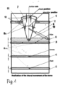
- Fig. 1 shows the embodiment of the device according to the invention which comprises a support frame 1 equipped with an immovable crossbar 2 of a holder, a movable crossbar 3 for the hip, a movable crossbar 4 for the knees, a movable crossbar 5 for the feet and an immovable crossbar 6 of the holder.
- the holder 7 is rotationally mounted on the immovable crossbar 6 by a slidable mechanism 9 for moving the holder along an arc, whereby its surface is moving along the immovable crossbar 2 on globular or rolling members 11 fitted therein.
- Actuators 8b holding the patient's head and shoulders with sling hangers 18 are mounted to the holder 7 and to the movable crossbars 3, 4, 5.
- the transverse movement of the holder 7 is actuated by a driving mechanism 9 mounted on the immovable crossbar 6. Thanks to the robust support frame 1 the patient is stabilized and feels safe.
- the holder 7 mounted rotationally at the rotation point 10 of the holder on the crossbar 6 and moving on rolling members 11 allows to acquire and to secure a desired position with a lateral movement of the patient's torso.
- Slidable assemblies 12 allow to adjust the position of the actuators of the sling hangers for the head and for the shoulders to anthropometric size of a particular patient.
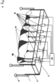
- the frame 1 In the corners of the frame 1 ( fig. 2 ) there are situated structural members 14 connected by a lifting mechanism 13 with track rollers 15.
- the torso of the patient 16 is laterally deviated in the device built on the track rollers 15 in such a manner that the body of the patient 16 situated horizontally, face up, is lifted by means of eight sling hangers taking hold of the head, the back in the points of shoulder girdle and pelvis girdle, and the calves, and the feet.
- the sling hangers 18 for the head, the shoulders, and the hip are at their ends connected in pairs with linear actuators 8 suspended in pairs on the horizontal support frame 1 transversely to the axis of the patient's spine. The movement of each of the linear actuators is individually controlled from a control system 17.
- the head and the shoulders of the suspended patient are supported by the sling hangers 18 of the linear actuators 8b mounted to the holder 7 whose transversal movement is provided by the holder's driving mechanism 9 along an arc within a designated range of the movement.
- the holder's 7 upper back surface moves with a swinging motion on the rolling members 11 installed in the immovable crossbar 2 of the support frame 1.
- Repositioning of the holder's drive (for example an actuator) which connects the holder 7 and the immovable crossbar 6 causes lateral deviation of the torso and the spine to a designated angle with the possibility for selecting an adequate frequency and amplitude of the relocation as set in the control system 17.
- the device allows for a precise, three-plane correction of scoliosis. Thanks to the lateral deflection of the spine with the patient in horizontal position on the movable base and also thanks to the three-plane stabilization of the hip in the transverse plane and in the sagittal plane a correction of the spine takes place.
- the device according to the invention allows for spinal correction in three planes and makes it possible to treat in a correct manner scoliosis, rheumatic and neurological diseases. Scoliosis that are improperly treated might lead to a reduced physical capacity of the patient, increased intensity of neurological disorders, permanent disability, and in extreme cases to heart or/and respiratory failure and premature death.
- the device according to the invention might be useful to improve efficiency of spine rehabilitation therapy, might be used in rehabilitation centres, in companies producing medical equipment as well as in hospital rehabilitation wards. It is targeted for physiotherapists in order to improve and create new possibilities of working with the patient substantially decreasing energy expenditures in the process of patient rehabilitation.
Landscapes
- Health & Medical Sciences (AREA)
- Public Health (AREA)
- Veterinary Medicine (AREA)
- Physical Education & Sports Medicine (AREA)
- Rehabilitation Therapy (AREA)
- Life Sciences & Earth Sciences (AREA)
- Animal Behavior & Ethology (AREA)
- Pain & Pain Management (AREA)
- Epidemiology (AREA)
- General Health & Medical Sciences (AREA)
- Engineering & Computer Science (AREA)
- Biomedical Technology (AREA)
- Neurology (AREA)
- Orthopedic Medicine & Surgery (AREA)
- Orthopedics, Nursing, And Contraception (AREA)
- Rehabilitation Tools (AREA)
Description
- The invention relates to a device for spine rehabilitation, particularly for patients with painful postural asymmetry, discopathy and degenerative illnesses.
- From the description of Polish utility model No
PL 60060 PL 176238 - From Polish patent
PL 209439B1 PL 226008B1 EP 2311424A1 discloses a device for physiotherapy and rehabilitation having a robust supporting structure in the form of a horizontal frame propped at its corners, having four cross elements out of which two middle are slidingly mounted on longitudinal rods of the frame and whose position can be adjusted. Suspended on internal rods there is a longitudinal member which can be pivoted horizontally. Cross-rods slidingly attached to the longitudinal member have on them mechanisms for fitting and adjusting length of slide lines on which the patient's body is suspended. Thanks to additional horizontal lines attached to the sling hanger it is possible to exert force acting along the axis of the spine. - From publication
WO 2007/017282A2 there is known an exercise apparatus having, in one of the embodiments of its frame design, a rod structure. The frame is suspended on the ceiling in a way that it can be rotated horizontally and vertically thanks to the use of a ball-and-socket joint and also lifted and lowered thanks to the use of a telescopic member. The frame has a longitudinal supporting member in the form of double rods or tubes. This member also acts as a guide for linear carriages with linear bearings that can move along it. Cross-rods fitted to the carriages have on their ends elements in the form of blocks or eyelets whose position on the rods can be adjusted and locked and which are designed for placing sling hangers on which patient's body is suspended above a bed. Moving parts can be power-driven, for example by an electric motor. - Moreover, from Polish patent description No
PL 217824 - The application
KR 2009 0130457 - The document
CN 106 074 088 discloses numerical control auxiliary motion device that comprises a main control single chip microcomputer, a device main body, a cuboid bracket, server motors, reduction gearboxes, winches, lifting belts and hooks, wherein the device main body is provided with a plane on which a person lies flat. - The object of the invention is to develop a device allowing to introduce a movement of lateral deviation of the patient's torso during his/her rehabilitation in suspension.
- The present invention provides a device for spine rehabilitation according to claim 1.
- A device for spine rehabilitation with the use of a method for lateral deviation of the patient's torso comprising a support frame, immovable crossbars, movable crossbars and a holder and actuator assemblies supporting the head, the arms, the hips, the knees and the feet of the patient characterised in that it is equipped with linear actuators mounted on the holder and to the movable crossbars that support the patient, whereby the holder has a driving mechanism, sliding horizontally, mounted on the immovable crossbar of the holder of the supporting frame and which, on its lower part, is fitted to the immovable crossbar equipped with a rotating mechanism. The holder's upper back surface moves on rolling members installed in the immovable crossbar of the holder. Sling hangers for the head and for the shoulders connected on their ends with two linear actuators are suspended in pairs on the movable holder. Moreover, the movement of each of the actuators is controlled individually from a control unit assisted by a computer with medical software. Preferably, the linear actuators in pairs for each of the sling hangers are connected with the holder by slidable assemblies in the direction longitudinal to the axis of the holder and thus allow to adjust positions of the actuators of the sling hanger for the head according to anthropometric size of a particular patient.
- A method for spine rehabilitation, not included in scope of the invention, using the device for lateral deviation of the torso of the patient suspended on the actuators takes place in the device where the patient's body is situated in substantially horizontal position, face up, and is lifted by four sling hangers that take hold of the patient's head, back in the points of shoulder girdle and pelvis girdle, and calves and each of the slings is connected on its ends with two linear actuators suspended in pairs on the horizontal support frame in the position perpendicular do the axis of the patient's spine, whereby the movements of each of the linear actuators is individually controlled from the control system, characterised in that the head and the shoulders of the suspended patient are supported by the actuators fitted in the holder whose transversal movement is provided by the rotating mechanism, whereas a slidable mechanism moves along an arc within a designated range in such a way that the holder's upper surface moves with a swinging motion on the rolling members fitted in the crossbar of the supporting frame, whereas movements of the actuators connected to the surface of the holder cause lateral deviation of the torso and the spine at a designated angle with the possibility of selecting proper frequency and amplitude of the deviations.
- The solution presented allows to carry out spine rehabilitation therapy in suspension with a dynamic lateral deviation of the torso optimally selected to a particular affection, with discretionarily varied, medically developed kinematics. The movements of the pairs of the actuators connected to the surface of the holder produces lateral deviation of the torso and of the spine up to a specified deviation angle with the possibility of selecting an adequate frequency and amplitude of the relocation, and, additionally, with various options of the longitudinal interaction of neighbouring sling hangers. For example, with the sling hanger for the pelvis girdle locked, side bending is induced by activating the shoulder girdle sling hanger. This kind of rehabilitation therapy, thanks to this solution, becomes safe and less burdensome while keeping the patient in safety and comfort. The exemplary embodiment of the invention is shown on the accompanying diagrammatic drawings.
-
Fig. 1 shows the embodiment of the device according to the invention which comprises a support frame 1 equipped with animmovable crossbar 2 of a holder, a movable crossbar 3 for the hip, a movable crossbar 4 for the knees, a movable crossbar 5 for the feet and an immovable crossbar 6 of the holder. Theholder 7 is rotationally mounted on the immovable crossbar 6 by a slidable mechanism 9 for moving the holder along an arc, whereby its surface is moving along theimmovable crossbar 2 on globular or rollingmembers 11 fitted therein.Actuators 8b holding the patient's head and shoulders withsling hangers 18 are mounted to theholder 7 and to the movable crossbars 3, 4, 5. The transverse movement of theholder 7 is actuated by a driving mechanism 9 mounted on the immovable crossbar 6. Thanks to the robust support frame 1 the patient is stabilized and feels safe. Theholder 7 mounted rotationally at therotation point 10 of the holder on the crossbar 6 and moving on rollingmembers 11 allows to acquire and to secure a desired position with a lateral movement of the patient's torso.Slidable assemblies 12 allow to adjust the position of the actuators of the sling hangers for the head and for the shoulders to anthropometric size of a particular patient. - In the corners of the frame 1 (
fig. 2 ) there are situated structural members 14 connected by a lifting mechanism 13 with track rollers 15. The torso of the patient 16 is laterally deviated in the device built on the track rollers 15 in such a manner that the body of the patient 16 situated horizontally, face up, is lifted by means of eight sling hangers taking hold of the head, the back in the points of shoulder girdle and pelvis girdle, and the calves, and the feet. Thesling hangers 18 for the head, the shoulders, and the hip are at their ends connected in pairs with linear actuators 8 suspended in pairs on the horizontal support frame 1 transversely to the axis of the patient's spine. The movement of each of the linear actuators is individually controlled from acontrol system 17. - The head and the shoulders of the suspended patient (
fig.1 ) are supported by thesling hangers 18 of thelinear actuators 8b mounted to theholder 7 whose transversal movement is provided by the holder's driving mechanism 9 along an arc within a designated range of the movement. The holder's 7 upper back surface moves with a swinging motion on the rollingmembers 11 installed in theimmovable crossbar 2 of the support frame 1. Repositioning of the holder's drive (for example an actuator) which connects theholder 7 and the immovable crossbar 6 causes lateral deviation of the torso and the spine to a designated angle with the possibility for selecting an adequate frequency and amplitude of the relocation as set in thecontrol system 17. - The device allows for a precise, three-plane correction of scoliosis. Thanks to the lateral deflection of the spine with the patient in horizontal position on the movable base and also thanks to the three-plane stabilization of the hip in the transverse plane and in the sagittal plane a correction of the spine takes place.
- Thanks to its design the device according to the invention allows for spinal correction in three planes and makes it possible to treat in a correct manner scoliosis, rheumatic and neurological diseases. Scoliosis that are improperly treated might lead to a reduced physical capacity of the patient, increased intensity of neurological disorders, permanent disability, and in extreme cases to heart or/and respiratory failure and premature death.
- The device according to the invention might be useful to improve efficiency of spine rehabilitation therapy, might be used in rehabilitation centres, in companies producing medical equipment as well as in hospital rehabilitation wards. It is targeted for physiotherapists in order to improve and create new possibilities of working with the patient substantially decreasing energy expenditures in the process of patient rehabilitation.
Claims (5)
- A device for spine rehabilitation comprising a support frame, immovable crossbars, movable crossbars and systems of actuators (8a) with attached sling hangers supporting a patient's hip, knees, and feet, the device for spine rehabilitation is further equipped with a holder (7) with mounted linear actuators (8b) which have attached sling hangers supporting the patient's head and shoulders, whereby the holder (7) has a driving mechanism (9) situated horizontally and mounted to an immovable crossbar (6) of the support frame (1) and whereby the holder (7) in its lower part is rotationally mounted, at the rotation point (10) of the holder (7), to the immovable crossbar (6), such that, in use, a lateral movement of the patient (16) suspended on the linear actuators (8) in the area of the head and the shoulders is carried out by the movement of the holder (7) by the driving mechanism (9) along an arc within a designated range of the movement.
- The device according to claim 1, characterised in that on an immovable crossbar (2) of the holder (7) there are globular or rolling members (11) which allow for a smooth movement of the holder (7) in the horizontal plane.
- The device according to claim 1, characterized in that the holder (7) with its upper back surface moves on the rolling members (11) installed in the immovable crossbar (2) of the holder.
- The device according to claim 1, characterized in that the support frame (1) with the suspended patient (16) and with structural members (14) is moved vertically by a lifting mechanism (13), and moves horizontally on track rollers (15).
- The device according to claim 1, characterized by that the actuators (8a, 8b) and drive mechanism (9) are connected to a control system (17).
Applications Claiming Priority (1)
| Application Number | Priority Date | Filing Date | Title |
|---|---|---|---|
| PL431381A PL245708B1 (en) | 2019-10-04 | 2019-10-04 | Device for rehabilitation of the spine and method of rehabilitation of the spine using the device for rehabilitation of the spine |
Publications (2)
| Publication Number | Publication Date |
|---|---|
| EP3799850A1 EP3799850A1 (en) | 2021-04-07 |
| EP3799850B1 true EP3799850B1 (en) | 2023-05-10 |
Family
ID=72852374
Family Applications (1)
| Application Number | Title | Priority Date | Filing Date |
|---|---|---|---|
| EP20199125.4A Active EP3799850B1 (en) | 2019-10-04 | 2020-09-29 | Device for spine rehabilitation and method of spine rehabilitation using said device for spine rehabilitation |
Country Status (3)
| Country | Link |
|---|---|
| US (1) | US11484458B2 (en) |
| EP (1) | EP3799850B1 (en) |
| PL (1) | PL245708B1 (en) |
Families Citing this family (2)
| Publication number | Priority date | Publication date | Assignee | Title |
|---|---|---|---|---|
| PL441328A1 (en) * | 2022-05-31 | 2023-12-04 | Uniwersytet Rzeszowski | Rehabilitation and development support device and its application |
| PL446634A1 (en) * | 2023-11-03 | 2024-06-03 | Akademia Górniczo-Hutnicza im. Stanisława Staszica w Krakowie | Method for monitoring and visualizing the process of spine relief rehabilitation and system for implementing the method |
Family Cites Families (24)
| Publication number | Priority date | Publication date | Assignee | Title |
|---|---|---|---|---|
| US5192304A (en) * | 1991-06-17 | 1993-03-09 | Rassman William R | Apparatus for manipulating back muscles |
| PL176238B1 (en) | 1995-05-29 | 1999-05-31 | Ziolkowski Tomasz | Scoliosis correcting adjuster |
| PL60060Y1 (en) | 1998-02-02 | 2003-12-31 | Janusz Leczynski | Versatile derotator and scoliosis corrector |
| US6098216A (en) * | 1998-10-28 | 2000-08-08 | Theodore A. Williamson | Convertible patient transport apparatus and method of transporting a patient |
| US7189214B1 (en) * | 2002-01-22 | 2007-03-13 | The Saunders Group, Inc. | Multi-axis cervical and lumbar traction table |
| US7494450B2 (en) * | 2004-05-14 | 2009-02-24 | Solomon Richard D | Variable unweighting and resistance training and stretching apparatus for use with a cardiovascular or other exercise device |
| PL209439B1 (en) | 2004-08-18 | 2011-09-30 | Ryszard Muskała | Postural modulator |
| DE102005038309A1 (en) * | 2005-08-11 | 2007-02-15 | Olaf Krell | exercise machine |
| US20070251010A1 (en) * | 2006-04-06 | 2007-11-01 | Nicolas Lara | Massage table |
| US7648473B1 (en) * | 2006-09-18 | 2010-01-19 | Jedheesh Peruvingal | Traction extension table |
| DE102007032148B4 (en) * | 2007-07-04 | 2010-12-16 | Mehrdad Rahimi | Training device, in particular for training the back muscles |
| US8257285B2 (en) * | 2008-04-09 | 2012-09-04 | Gerry Cook | Traction bed with vibrator assembly |
| US20090255543A1 (en) * | 2008-04-14 | 2009-10-15 | Masumi Oyama | Method of chiropractic treatment |
| KR100968840B1 (en) * | 2008-06-16 | 2010-07-09 | 유진곤 | Auto flexion-traction apparatus with massage therapy function |
| EP2311424A1 (en) | 2009-10-14 | 2011-04-20 | Powersling GmbH & Co. KG | Sling table for carrying out physiotherapy and rehabilitation and functional element for such a sling table |
| US10548798B2 (en) * | 2010-03-30 | 2020-02-04 | Enraf-Nonius B.V. | Physiotherapy apparatus |
| PL217824B1 (en) | 2010-06-24 | 2014-08-29 | Radosław Raźniewski | Device for scoliosis treatment |
| US20130184615A1 (en) * | 2012-01-04 | 2013-07-18 | Kerry Johnson | Spinal Correction Method and Device |
| RU2520248C2 (en) * | 2012-01-10 | 2014-06-20 | Ильдар Фарвазович Рахматуллин | Method for therapeutic exercises and apparatus for therapeutic exercises |
| ITRM20120596A1 (en) * | 2012-11-27 | 2014-05-28 | Bios Project Srl | MASSAGE MACHINE WITH TILTING BED PROVIDED FOR SITTING |
| PL226008B1 (en) | 2013-10-14 | 2017-06-30 | Akademia Górniczo Hutnicza Im Stanisława Staszica W Krakowie | Device for stimulation of muscles and rehabilitation of backbone |
| US10219965B2 (en) * | 2014-05-26 | 2019-03-05 | Bass Morris Pty Ltd | Spine treatment apparatus |
| CN106074088A (en) * | 2016-07-12 | 2016-11-09 | 刘刚 | The numerical control auxiliary moving devices of human body attitude change and method |
| US11179284B2 (en) * | 2016-11-25 | 2021-11-23 | Niklaus Emanuele STOCKER | Mover device for persons with reduced mobility |
-
2019
- 2019-10-04 PL PL431381A patent/PL245708B1/en unknown
-
2020
- 2020-09-29 EP EP20199125.4A patent/EP3799850B1/en active Active
- 2020-09-30 US US17/037,699 patent/US11484458B2/en active Active
Also Published As
| Publication number | Publication date |
|---|---|
| US11484458B2 (en) | 2022-11-01 |
| US20210100712A1 (en) | 2021-04-08 |
| PL431381A1 (en) | 2021-04-06 |
| PL245708B1 (en) | 2024-09-23 |
| EP3799850A1 (en) | 2021-04-07 |
Similar Documents
| Publication | Publication Date | Title |
|---|---|---|
| TWI491387B (en) | Restraint, reposition, traction and exercise device and method | |
| US4915101A (en) | Rotatable treatment table having adjustable support assemblies | |
| EP3799850B1 (en) | Device for spine rehabilitation and method of spine rehabilitation using said device for spine rehabilitation | |
| EP2370042B1 (en) | Method of passive mechanotherapy and exercise machine for implementation thereof | |
| CN105769506A (en) | Lower limb rehabilitation robot | |
| US5782869A (en) | Multi-trauma therapeutic machine | |
| CN102551943A (en) | Three-dimensional space cervical vertebrae rehabilitation instrument | |
| EP1617794B1 (en) | Calf and foot support and adjustment assembly | |
| CN110433022A (en) | A kind of lumbar vertebra tractor driven using pneumatic muscles | |
| CN111728841B (en) | Orthopedic spine correction massage device with far infrared treatment function | |
| CN113730175A (en) | Flexible cross traction rehabilitation bed | |
| EP2842535A1 (en) | Gravity scoliosis correction device | |
| CN205411569U (en) | Recovered robot of low limbs | |
| CN105434091A (en) | Spinal column pressure reducing equipment | |
| CN115089361A (en) | Traction support equipment for orthopedic nursing | |
| GB2152381A (en) | Physiotherapy table for traction and/or massage | |
| CN111658420B (en) | Orthopedic spine correction massage device | |
| JP2019526317A (en) | Device for moving a bed, in particular a care bed, a sick bed, a hospital bed or an intensive care bed, from a horizontal position to an inclined position with respect to its longitudinal side | |
| CN108524195B (en) | Orthopedics rehabilitation device | |
| CN207722045U (en) | A kind of novel orthopaedics spinal injury treatment chair | |
| CN212038121U (en) | Shank and backbone nursing treatment bed | |
| RU86868U1 (en) | TABLE FOR MASSAGE AND MANUAL THERAPY | |
| KR20100012180A (en) | Exercise device | |
| RU2766776C1 (en) | Table for massage, manual therapy and spinal traction | |
| RU103071U1 (en) | SPRING EXERCISE SIMULATOR |
Legal Events
| Date | Code | Title | Description |
|---|---|---|---|
| PUAI | Public reference made under article 153(3) epc to a published international application that has entered the european phase |
Free format text: ORIGINAL CODE: 0009012 |
|
| STAA | Information on the status of an ep patent application or granted ep patent |
Free format text: STATUS: THE APPLICATION HAS BEEN PUBLISHED |
|
| AK | Designated contracting states |
Kind code of ref document: A1 Designated state(s): AL AT BE BG CH CY CZ DE DK EE ES FI FR GB GR HR HU IE IS IT LI LT LU LV MC MK MT NL NO PL PT RO RS SE SI SK SM TR |
|
| AX | Request for extension of the european patent |
Extension state: BA ME |
|
| STAA | Information on the status of an ep patent application or granted ep patent |
Free format text: STATUS: REQUEST FOR EXAMINATION WAS MADE |
|
| 17P | Request for examination filed |
Effective date: 20211001 |
|
| RBV | Designated contracting states (corrected) |
Designated state(s): AL AT BE BG CH CY CZ DE DK EE ES FI FR GB GR HR HU IE IS IT LI LT LU LV MC MK MT NL NO PL PT RO RS SE SI SK SM TR |
|
| RIC1 | Information provided on ipc code assigned before grant |
Ipc: A61H 1/00 20060101ALI20221109BHEP Ipc: A61H 1/02 20060101AFI20221109BHEP |
|
| GRAP | Despatch of communication of intention to grant a patent |
Free format text: ORIGINAL CODE: EPIDOSNIGR1 |
|
| STAA | Information on the status of an ep patent application or granted ep patent |
Free format text: STATUS: GRANT OF PATENT IS INTENDED |
|
| INTG | Intention to grant announced |
Effective date: 20221221 |
|
| GRAS | Grant fee paid |
Free format text: ORIGINAL CODE: EPIDOSNIGR3 |
|
| GRAA | (expected) grant |
Free format text: ORIGINAL CODE: 0009210 |
|
| STAA | Information on the status of an ep patent application or granted ep patent |
Free format text: STATUS: THE PATENT HAS BEEN GRANTED |
|
| AK | Designated contracting states |
Kind code of ref document: B1 Designated state(s): AL AT BE BG CH CY CZ DE DK EE ES FI FR GB GR HR HU IE IS IT LI LT LU LV MC MK MT NL NO PL PT RO RS SE SI SK SM TR |
|
| REG | Reference to a national code |
Ref country code: GB Ref legal event code: FG4D |
|
| REG | Reference to a national code |
Ref country code: AT Ref legal event code: REF Ref document number: 1566028 Country of ref document: AT Kind code of ref document: T Effective date: 20230515 Ref country code: CH Ref legal event code: EP |
|
| REG | Reference to a national code |
Ref country code: DE Ref legal event code: R096 Ref document number: 602020010673 Country of ref document: DE |
|
| REG | Reference to a national code |
Ref country code: IE Ref legal event code: FG4D |
|
| P01 | Opt-out of the competence of the unified patent court (upc) registered |
Effective date: 20230529 |
|
| REG | Reference to a national code |
Ref country code: LT Ref legal event code: MG9D |
|
| REG | Reference to a national code |
Ref country code: NL Ref legal event code: MP Effective date: 20230510 |
|
| REG | Reference to a national code |
Ref country code: AT Ref legal event code: MK05 Ref document number: 1566028 Country of ref document: AT Kind code of ref document: T Effective date: 20230510 |
|
| PG25 | Lapsed in a contracting state [announced via postgrant information from national office to epo] |
Ref country code: SE Free format text: LAPSE BECAUSE OF FAILURE TO SUBMIT A TRANSLATION OF THE DESCRIPTION OR TO PAY THE FEE WITHIN THE PRESCRIBED TIME-LIMIT Effective date: 20230510 Ref country code: PT Free format text: LAPSE BECAUSE OF FAILURE TO SUBMIT A TRANSLATION OF THE DESCRIPTION OR TO PAY THE FEE WITHIN THE PRESCRIBED TIME-LIMIT Effective date: 20230911 Ref country code: NO Free format text: LAPSE BECAUSE OF FAILURE TO SUBMIT A TRANSLATION OF THE DESCRIPTION OR TO PAY THE FEE WITHIN THE PRESCRIBED TIME-LIMIT Effective date: 20230810 Ref country code: NL Free format text: LAPSE BECAUSE OF FAILURE TO SUBMIT A TRANSLATION OF THE DESCRIPTION OR TO PAY THE FEE WITHIN THE PRESCRIBED TIME-LIMIT Effective date: 20230510 Ref country code: ES Free format text: LAPSE BECAUSE OF FAILURE TO SUBMIT A TRANSLATION OF THE DESCRIPTION OR TO PAY THE FEE WITHIN THE PRESCRIBED TIME-LIMIT Effective date: 20230510 Ref country code: AT Free format text: LAPSE BECAUSE OF FAILURE TO SUBMIT A TRANSLATION OF THE DESCRIPTION OR TO PAY THE FEE WITHIN THE PRESCRIBED TIME-LIMIT Effective date: 20230510 |
|
| PG25 | Lapsed in a contracting state [announced via postgrant information from national office to epo] |
Ref country code: RS Free format text: LAPSE BECAUSE OF FAILURE TO SUBMIT A TRANSLATION OF THE DESCRIPTION OR TO PAY THE FEE WITHIN THE PRESCRIBED TIME-LIMIT Effective date: 20230510 Ref country code: PL Free format text: LAPSE BECAUSE OF FAILURE TO SUBMIT A TRANSLATION OF THE DESCRIPTION OR TO PAY THE FEE WITHIN THE PRESCRIBED TIME-LIMIT Effective date: 20230510 Ref country code: LV Free format text: LAPSE BECAUSE OF FAILURE TO SUBMIT A TRANSLATION OF THE DESCRIPTION OR TO PAY THE FEE WITHIN THE PRESCRIBED TIME-LIMIT Effective date: 20230510 Ref country code: LT Free format text: LAPSE BECAUSE OF FAILURE TO SUBMIT A TRANSLATION OF THE DESCRIPTION OR TO PAY THE FEE WITHIN THE PRESCRIBED TIME-LIMIT Effective date: 20230510 Ref country code: IS Free format text: LAPSE BECAUSE OF FAILURE TO SUBMIT A TRANSLATION OF THE DESCRIPTION OR TO PAY THE FEE WITHIN THE PRESCRIBED TIME-LIMIT Effective date: 20230910 Ref country code: HR Free format text: LAPSE BECAUSE OF FAILURE TO SUBMIT A TRANSLATION OF THE DESCRIPTION OR TO PAY THE FEE WITHIN THE PRESCRIBED TIME-LIMIT Effective date: 20230510 Ref country code: GR Free format text: LAPSE BECAUSE OF FAILURE TO SUBMIT A TRANSLATION OF THE DESCRIPTION OR TO PAY THE FEE WITHIN THE PRESCRIBED TIME-LIMIT Effective date: 20230811 |
|
| PG25 | Lapsed in a contracting state [announced via postgrant information from national office to epo] |
Ref country code: FI Free format text: LAPSE BECAUSE OF FAILURE TO SUBMIT A TRANSLATION OF THE DESCRIPTION OR TO PAY THE FEE WITHIN THE PRESCRIBED TIME-LIMIT Effective date: 20230510 |
|
| PG25 | Lapsed in a contracting state [announced via postgrant information from national office to epo] |
Ref country code: SK Free format text: LAPSE BECAUSE OF FAILURE TO SUBMIT A TRANSLATION OF THE DESCRIPTION OR TO PAY THE FEE WITHIN THE PRESCRIBED TIME-LIMIT Effective date: 20230510 |
|
| PG25 | Lapsed in a contracting state [announced via postgrant information from national office to epo] |
Ref country code: SM Free format text: LAPSE BECAUSE OF FAILURE TO SUBMIT A TRANSLATION OF THE DESCRIPTION OR TO PAY THE FEE WITHIN THE PRESCRIBED TIME-LIMIT Effective date: 20230510 Ref country code: SK Free format text: LAPSE BECAUSE OF FAILURE TO SUBMIT A TRANSLATION OF THE DESCRIPTION OR TO PAY THE FEE WITHIN THE PRESCRIBED TIME-LIMIT Effective date: 20230510 Ref country code: RO Free format text: LAPSE BECAUSE OF FAILURE TO SUBMIT A TRANSLATION OF THE DESCRIPTION OR TO PAY THE FEE WITHIN THE PRESCRIBED TIME-LIMIT Effective date: 20230510 Ref country code: EE Free format text: LAPSE BECAUSE OF FAILURE TO SUBMIT A TRANSLATION OF THE DESCRIPTION OR TO PAY THE FEE WITHIN THE PRESCRIBED TIME-LIMIT Effective date: 20230510 Ref country code: DK Free format text: LAPSE BECAUSE OF FAILURE TO SUBMIT A TRANSLATION OF THE DESCRIPTION OR TO PAY THE FEE WITHIN THE PRESCRIBED TIME-LIMIT Effective date: 20230510 Ref country code: CZ Free format text: LAPSE BECAUSE OF FAILURE TO SUBMIT A TRANSLATION OF THE DESCRIPTION OR TO PAY THE FEE WITHIN THE PRESCRIBED TIME-LIMIT Effective date: 20230510 |
|
| REG | Reference to a national code |
Ref country code: DE Ref legal event code: R097 Ref document number: 602020010673 Country of ref document: DE |
|
| PLBE | No opposition filed within time limit |
Free format text: ORIGINAL CODE: 0009261 |
|
| STAA | Information on the status of an ep patent application or granted ep patent |
Free format text: STATUS: NO OPPOSITION FILED WITHIN TIME LIMIT |
|
| 26N | No opposition filed |
Effective date: 20240213 |
|
| REG | Reference to a national code |
Ref country code: CH Ref legal event code: PL |
|
| PG25 | Lapsed in a contracting state [announced via postgrant information from national office to epo] |
Ref country code: SI Free format text: LAPSE BECAUSE OF FAILURE TO SUBMIT A TRANSLATION OF THE DESCRIPTION OR TO PAY THE FEE WITHIN THE PRESCRIBED TIME-LIMIT Effective date: 20230510 |
|
| PG25 | Lapsed in a contracting state [announced via postgrant information from national office to epo] |
Ref country code: LU Free format text: LAPSE BECAUSE OF NON-PAYMENT OF DUE FEES Effective date: 20230929 |
|
| REG | Reference to a national code |
Ref country code: BE Ref legal event code: MM Effective date: 20230930 |
|
| PG25 | Lapsed in a contracting state [announced via postgrant information from national office to epo] |
Ref country code: SI Free format text: LAPSE BECAUSE OF FAILURE TO SUBMIT A TRANSLATION OF THE DESCRIPTION OR TO PAY THE FEE WITHIN THE PRESCRIBED TIME-LIMIT Effective date: 20230510 Ref country code: LU Free format text: LAPSE BECAUSE OF NON-PAYMENT OF DUE FEES Effective date: 20230929 Ref country code: IT Free format text: LAPSE BECAUSE OF FAILURE TO SUBMIT A TRANSLATION OF THE DESCRIPTION OR TO PAY THE FEE WITHIN THE PRESCRIBED TIME-LIMIT Effective date: 20230510 Ref country code: MC Free format text: LAPSE BECAUSE OF FAILURE TO SUBMIT A TRANSLATION OF THE DESCRIPTION OR TO PAY THE FEE WITHIN THE PRESCRIBED TIME-LIMIT Effective date: 20230510 |
|
| REG | Reference to a national code |
Ref country code: IE Ref legal event code: MM4A |
|
| PG25 | Lapsed in a contracting state [announced via postgrant information from national office to epo] |
Ref country code: IE Free format text: LAPSE BECAUSE OF NON-PAYMENT OF DUE FEES Effective date: 20230929 |
|
| PG25 | Lapsed in a contracting state [announced via postgrant information from national office to epo] |
Ref country code: CH Free format text: LAPSE BECAUSE OF NON-PAYMENT OF DUE FEES Effective date: 20230930 |
|
| PG25 | Lapsed in a contracting state [announced via postgrant information from national office to epo] |
Ref country code: IE Free format text: LAPSE BECAUSE OF NON-PAYMENT OF DUE FEES Effective date: 20230929 Ref country code: CH Free format text: LAPSE BECAUSE OF NON-PAYMENT OF DUE FEES Effective date: 20230930 |
|
| PG25 | Lapsed in a contracting state [announced via postgrant information from national office to epo] |
Ref country code: BE Free format text: LAPSE BECAUSE OF NON-PAYMENT OF DUE FEES Effective date: 20230930 |
|
| PGFP | Annual fee paid to national office [announced via postgrant information from national office to epo] |
Ref country code: DE Payment date: 20240725 Year of fee payment: 5 |
|
| PGFP | Annual fee paid to national office [announced via postgrant information from national office to epo] |
Ref country code: GB Payment date: 20240725 Year of fee payment: 5 |
|
| PGFP | Annual fee paid to national office [announced via postgrant information from national office to epo] |
Ref country code: FR Payment date: 20240725 Year of fee payment: 5 |