EP3799394B1 - Peer-überwachung von bauteilen industrieller automatisierungssysteme - Google Patents
Peer-überwachung von bauteilen industrieller automatisierungssysteme Download PDFInfo
- Publication number
- EP3799394B1 EP3799394B1 EP20191255.7A EP20191255A EP3799394B1 EP 3799394 B1 EP3799394 B1 EP 3799394B1 EP 20191255 A EP20191255 A EP 20191255A EP 3799394 B1 EP3799394 B1 EP 3799394B1
- Authority
- EP
- European Patent Office
- Prior art keywords
- network
- network device
- configuration file
- backup
- device configuration
- Prior art date
- Legal status (The legal status is an assumption and is not a legal conclusion. Google has not performed a legal analysis and makes no representation as to the accuracy of the status listed.)
- Active
Links
Images


Classifications
-
- G—PHYSICS
- G05—CONTROLLING; REGULATING
- G05B—CONTROL OR REGULATING SYSTEMS IN GENERAL; FUNCTIONAL ELEMENTS OF SUCH SYSTEMS; MONITORING OR TESTING ARRANGEMENTS FOR SUCH SYSTEMS OR ELEMENTS
- G05B19/00—Program-control systems
- G05B19/02—Program-control systems electric
- G05B19/418—Total factory control, i.e. centrally controlling a plurality of machines, e.g. direct or distributed numerical control [DNC], flexible manufacturing systems [FMS], integrated manufacturing systems [IMS] or computer integrated manufacturing [CIM]
- G05B19/4185—Total factory control, i.e. centrally controlling a plurality of machines, e.g. direct or distributed numerical control [DNC], flexible manufacturing systems [FMS], integrated manufacturing systems [IMS] or computer integrated manufacturing [CIM] characterised by the network communication
-
- H—ELECTRICITY
- H04—ELECTRIC COMMUNICATION TECHNIQUE
- H04L—TRANSMISSION OF DIGITAL INFORMATION, e.g. TELEGRAPHIC COMMUNICATION
- H04L67/00—Network arrangements or protocols for supporting network services or applications
- H04L67/34—Network arrangements or protocols for supporting network services or applications involving the movement of software or configuration parameters
-
- G—PHYSICS
- G05—CONTROLLING; REGULATING
- G05B—CONTROL OR REGULATING SYSTEMS IN GENERAL; FUNCTIONAL ELEMENTS OF SUCH SYSTEMS; MONITORING OR TESTING ARRANGEMENTS FOR SUCH SYSTEMS OR ELEMENTS
- G05B19/00—Program-control systems
- G05B19/02—Program-control systems electric
- G05B19/18—Numerical control [NC], i.e. automatically operating machines, in particular machine tools, e.g. in a manufacturing environment, so as to execute positioning, movement or co-ordinated operations by means of program data in numerical form
- G05B19/408—Numerical control [NC], i.e. automatically operating machines, in particular machine tools, e.g. in a manufacturing environment, so as to execute positioning, movement or co-ordinated operations by means of program data in numerical form characterised by data handling or data format, e.g. reading, buffering or conversion of data
- G05B19/4083—Adapting program, configuration
-
- H—ELECTRICITY
- H04—ELECTRIC COMMUNICATION TECHNIQUE
- H04L—TRANSMISSION OF DIGITAL INFORMATION, e.g. TELEGRAPHIC COMMUNICATION
- H04L41/00—Arrangements for maintenance, administration or management of data switching networks, e.g. of packet switching networks
- H04L41/08—Configuration management of networks or network elements
- H04L41/0803—Configuration setting
- H04L41/0823—Configuration setting characterised by the purposes of a change of settings, e.g. optimising configuration for enhancing reliability
-
- H—ELECTRICITY
- H04—ELECTRIC COMMUNICATION TECHNIQUE
- H04L—TRANSMISSION OF DIGITAL INFORMATION, e.g. TELEGRAPHIC COMMUNICATION
- H04L41/00—Arrangements for maintenance, administration or management of data switching networks, e.g. of packet switching networks
- H04L41/08—Configuration management of networks or network elements
- H04L41/0803—Configuration setting
- H04L41/084—Configuration by using pre-existing information, e.g. using templates or copying from other elements
- H04L41/0843—Configuration by using pre-existing information, e.g. using templates or copying from other elements based on generic templates
-
- H—ELECTRICITY
- H04—ELECTRIC COMMUNICATION TECHNIQUE
- H04L—TRANSMISSION OF DIGITAL INFORMATION, e.g. TELEGRAPHIC COMMUNICATION
- H04L41/00—Arrangements for maintenance, administration or management of data switching networks, e.g. of packet switching networks
- H04L41/08—Configuration management of networks or network elements
- H04L41/085—Retrieval of network configuration; Tracking network configuration history
- H04L41/0853—Retrieval of network configuration; Tracking network configuration history by actively collecting configuration information or by backing up configuration information
- H04L41/0856—Retrieval of network configuration; Tracking network configuration history by actively collecting configuration information or by backing up configuration information by backing up or archiving configuration information
-
- H—ELECTRICITY
- H04—ELECTRIC COMMUNICATION TECHNIQUE
- H04L—TRANSMISSION OF DIGITAL INFORMATION, e.g. TELEGRAPHIC COMMUNICATION
- H04L67/00—Network arrangements or protocols for supporting network services or applications
- H04L67/01—Protocols
- H04L67/10—Protocols in which an application is distributed across nodes in the network
- H04L67/104—Peer-to-peer [P2P] networks
- H04L67/1061—Peer-to-peer [P2P] networks using node-based peer discovery mechanisms
- H04L67/1063—Discovery through centralising entities
-
- H—ELECTRICITY
- H04—ELECTRIC COMMUNICATION TECHNIQUE
- H04L—TRANSMISSION OF DIGITAL INFORMATION, e.g. TELEGRAPHIC COMMUNICATION
- H04L67/00—Network arrangements or protocols for supporting network services or applications
- H04L67/01—Protocols
- H04L67/12—Protocols specially adapted for proprietary or special-purpose networking environments, e.g. medical networks, sensor networks, networks in vehicles or remote metering networks
-
- G—PHYSICS
- G05—CONTROLLING; REGULATING
- G05B—CONTROL OR REGULATING SYSTEMS IN GENERAL; FUNCTIONAL ELEMENTS OF SUCH SYSTEMS; MONITORING OR TESTING ARRANGEMENTS FOR SUCH SYSTEMS OR ELEMENTS
- G05B2219/00—Program-control systems
- G05B2219/10—Plc systems
- G05B2219/11—Plc I-O input output
- G05B2219/1137—Peer to peer communication
-
- H—ELECTRICITY
- H04—ELECTRIC COMMUNICATION TECHNIQUE
- H04L—TRANSMISSION OF DIGITAL INFORMATION, e.g. TELEGRAPHIC COMMUNICATION
- H04L43/00—Arrangements for monitoring or testing data switching networks
- H04L43/10—Active monitoring, e.g. heartbeat, ping or trace-route
Definitions
- This disclosure relates generally to systems and methods for providing a control and monitoring system within an industrial automation system. More particularly, embodiments of the present disclosure are directed toward systems to provide a self-healing, peer-to-peer communication network within the industrial automation system.
- Industrial automation systems may include automation control and monitoring systems.
- the automation control and monitoring systems may monitor statuses and/or receive information from a wide range of devices, such as valves, electric motors, a wide range of sensors, other suitable monitoring devices, or the like.
- One or more components of the automation control and monitoring systems such as programming terminals, automation controllers, input/output (I/O) modules, communication networks, human-machine interface (HMI) terminals, and the like, may use the statuses and/or received information to provide alerts to operators to change or adjust operation of one or more components of the industrial automation system (e.g., such as adjusting operation of one or more actuators), to manage the industrial automation system, or the like.
- I/O input/output
- HMI human-machine interface
- the components described above may operate in coordination with a control system.
- a control system may be a programmable logic controller (PLC) or a programmable logic device (PLD).
- PLC programmable logic controller
- PLD programmable logic device
- the control system may receive the statuses and/or information from the wide range of devices, and use the statuses and/or information to make control decisions.
- An example of a control decision is determining whether to slow or halt operation of a motor or load.
- the components described above and/or the control system may operate according to stored device configurations.
- a device configuration may include processing instructions, settings, operating ranges, indications of connections to other components within the industrial automation system, or the like, and may be used to customize an operation of the components and/or the control system to a particular process.
- the device configuration When components and/or the control system are replaced, the device configuration may be lost and may be reinstalled for the replacement component and/or control system.
- the replacement process may be a lengthy process that introduces opportunities for operator error.
- a configuration manager software may be used to replace the configuration of the component and/or control system, thereby increasing time and processing resources used to prepare the replacement component and/or control system for use.
- US 2006/047778 A1 discloses that device configurations are stored in a system including at least two intelligent field devices (IFDs) connected by a communications connection.
- a configuration for a first IFD is stored in the first IFD, and a backup of the configuration for the first IFD is stored in at least one other IFD.
- Storing a configuration for the first IFD includes having the first IFD request a configuration from at least one other IFD using the communications connection, an IFD having a stored backup of the configuration for the first IFD transmitting the backup to the first IFD using the communications connection, and the first IFD receiving the transmitted backup and storing the received backup in the first IFD as the configuration for the first IFD.
- Storing a backup of the configuration for the first IFD includes having the first IFD transmit a backup of the configuration for the first IFD to at least one other IFD using the communications connection, and having the at least one other IFD receive and store the backup of the configuration.
- US 2010/153771 A1 discloses that systems and methods are provided for peer-to-peer exchange of data in a control system.
- Decentralized storage and multi-access paths provide complete sets of data without dependence on a specific or pre-defined data source or access paths.
- Peer-to-peer distribution of data resources is be based on available access networks resources and optimization of response times in the control system. When client requests a data resource, all the locations of the data resource and the quickest source to retrieve it are automatically determined.
- US 2017/078382 A1 discloses a method to reduce group reformation time and maintain seamless connectivity in a peer-to-peer network at the time of disappearance of the Group Owner (GO).
- Each of the nodes is provided with an emergency leader list which prioritizes a predetermined number of emergency leader nodes each of which is a client node having intent of acting as an emergency leader, wherein the emergency leader list is prepared right at the time of group formation.
- the emergency leader nodes broadcast beacons when a leader node disappears from the group without notice.
- Each of the client nodes barring a first-priority emergency leader node of the emergency leader list connects to a highest priority one of emergency leader nodes detected by the client node.
- a system is provided according to claim 1.
- a tangible, non-transitory computer-readable medium is provided according to claim 13.
- the present disclosure is generally directed towards systems and methods that may be useful to improve the replacement process associated with the components and/or the control system of the industrial automation system.
- methods described herein may use peer-level control to provide a self-healing, peer-to-peer communication network within an industrial automation system to manage the storage of and access to backup device configuration files after a network device loses a device configuration file or is replaced with a device with an incomplete device configuration file.
- industrial automation systems may include automation control and monitoring systems (e.g., industrial control systems).
- the automation control and monitoring systems may monitor statuses and/or receive information from a wide range of devices, such as valves, electric motors, sensors, other suitable monitoring devices, or the like. These components may communicate with each other via a suitable network, such as a peer-to-peer communication network.
- Devices coupled via a peer-to-peer communication network may be configured according to a device configuration file.
- the device configuration file may include processing instructions, settings, operating ranges, indications of connections to other components within the industrial automation system, or the like, and may be used to customize an operation of devices and/or the control system to a particular process.
- the device configuration file may be lost or removed from the device and/or may not be transferred automatically to a replacement device.
- a configuration manager software may replace the configuration of the device and/or control system, thereby increasing time and processing resources used to prepare the replacement device and/or control system for use.
- an intermediary control system such as a programmable logic controller (PLC) or a programmable logic device (PLD) may control communications between components in the peer-to-peer communication network, including communications between the configuration manager software and the network devices.
- the components may manage communications without an intermediary control system by enabling the network devices to directly communicate with each other.
- Communication networks that include components configurable to communicate without the intermediary control system may be relatively more resilient to unpredicted or unexpected loss of the control system (e.g., control system unexpectedly going offline) than those with the intermediary control system since the communication network may continue to operate even when the intermediary control system is unusable.
- network devices may store backup device configuration files associated with operation of the peer-to-peer communication network.
- a peer network device may transmit a backup device configuration file to replace the lost or removed device configuration file.
- a first device may store a first device configuration file defining settings, operations, thresholds, or the like for the first device while simultaneously storing a second device configuration file that defines settings, operations, thresholds, or the like for a second device.
- the first device may transmit the second backup device configuration file (e.g., backup of the original device configuration file) to the second device for configuration.
- the redundancy and sharing operations of the device configuration files between the devices may occur independent of an intermediary control system. Redundant device configuration file storage may further improve a resiliency of the peer-to-peer communication network to unpredicted or unexpected loss of the intermediary control system (e.g., control system unexpectedly going offline) since the peer-to-peer network may operate independent of an intermediary control system (e.g., PLC) guiding individual transactions or communications.
- PLC intermediary control system
- systems and methods that improve management of the peer-to-peer communication network may include methods that enable discovery of data endpoints (e.g., recipient device) in response to a device being installed into the peer-to-peer communication network.
- a receiving device e.g., data consuming device, consumer
- a transmitting device may perform a discovery operation on the peer-to-peer communication network. For example, when a receiving device is discovered by a transmitting device (e.g., data producing device, producer), the transmitting device may initialize a sub-network (subnet) between the devices, such that a subnet is a portion of a communication network logically designated for transmitting messages between two or more network devices.
- subnet sub-net
- the transmitting device may transmit the device configuration file to receiving devices via the established subnet.
- the respective device that discovered the new device may automatically transmit the backup device configuration file from the respective device to the newly installed device, thereby initializing the newly installed device to the peer-to-peer communication network (e.g., reconfiguring the replacement device).
- a peer-to-peer communication network that operates to backup device configuration files may enable the peer-to-peer communication network to "self-heal" or automatically reconfigure devices added to the peer-to-peer communication network to replace a previous network device.
- either the receiving device or the transmitting device may start a data transaction in the above-described peer-to-peer network.
- an intercommunicating device pair may not wait to receive a control signal from the intermediary control system to start a data transmission. This may improve data communication latencies of the industrial automation system since the transmitting devices may transmit data to receiving devices at will and without latencies associated with an intermediary control system synchronizing communications.
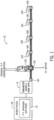
- FIG. 1 is a block diagram of an example peer-to-peer communication network (P-P network) 10 that may be employed in an industrial automation system.
- the P-P network 10 includes network devices 12 (12A, 12B, 12C, 12D, 12E).
- Each of the network devices 12 may include sensing circuitry for monitoring an industrial automation system.
- Sensing circuitry of the network devices 12 may generate output data indicative of an operation and/or aspect of the industrial automation system.
- a network device 12A may detect when an input button is pressed, such as to start a motor.
- Some network devices 12 may include sensing circuitry that generates digital or analog values representative of a sensed voltage, current, pressure, moisture level, audio level, containment level, or any other suitable parameter associated with operation of the industrial automation system. Sensing data resulting from the sensing circuitry may be of any suitable format, and thus may include one or more analog electrical signals, digital data signals, pulse-width-modulated data signals, or the like. It is noted that the acquired data may be transmitted via any wired or wireless communication signals, such as radio frequency signals. Network devices 12 may also include a variety of scanners, gauges, valves, flow meters, or the like, and may each generate sensing data.
- Data generated by the network devices 12 may be used in controlling operations of the industrial automation system, such as by using the data as an input in a control loop.
- the P-P network 10 may represent a subset or portion of an industrial control network used to manage operations of the industrial automation system.
- Each of the network devices 12 may receive communication signals and/or power supply signals from a communication gateway and power supply device 14 and/or other network devices 12.
- the network devices 12 may use these supplied signals to perform sensing operations, to transmit output operations, or the like.
- the network device 12B may detect when a corresponding input button has been pressed as part of a stop request, and the network device 12B may use the supplied signals from the communication gateway and power supply device 14 to detect that the input button has been pressed when a contact closes, completing an electrical coupling between the sensing circuitry and a line supplying an electrical signal from the communication gateway and power supply device 14, thereby generating a detectable voltage or current.
- One or more of the network devices 12 may couple to a load.
- the network device 12E may be a motor starter that couples to a motor and controls an operation of the motor based on control signals output from input/output circuitry 16E.
- Each of the network devices 12 may be coupled to the P-P network via the respective input/output circuitry 16.
- Each of the network devices 12 may include other input/output circuitry to couple to non-network components (e.g., loads).
- Data generated by the network devices 12 may be packaged in a message and transmitted to network devices on the P-P network 10 and/or other devices via the communication gateway and power supply device 14 through the P-P network 10.
- the network devices 12 may operate responsive to device configuration files.
- a device configuration file may define processing instructions, settings, operating ranges, indications of connections to other components within the industrial automation system, or the like, and may be used to customize an operation of devices and/or the control system to a particular process. In this way, operation of the network devices 12 may be define by respectively stored device configuration files.
- the network device 12A may store a first device configuration file while the network device 12B may store a second device configuration file different from the first device configuration file.
- the network devices 12 may lose the stored device configuration file and/or one or more of the network devices 12 may be replaced, resulting in a lack of the device configuration file.
- a device configuration file may be transmitted to the network device 12 during operation of and/or after a first initialization of the P-P network 10 (e.g., a first power on of the P-P network 10 as may be the case with a device replacement operation).
- a workstation 18 e.g., computing device
- a P-P manager software 20 may transmit a device configuration file to one of the network devices 12 to initialize operations of the P-P network 10.
- the workstation 18 may transmit a device configuration file to the network device 12A to reconfigure or initialize the network device 12A according to the device configuration file.
- this process may be lengthy and complicated since the P-P manager software 20 may incur processing delays while transmitting the device configuration file.
- each network device 12 may store a backup copy of the device configuration files of the P-P network 10. In this way, if any of the network devices 12 lose the corresponding device configuration file, a backup copy of the corresponding device configuration file may be restored to the network device 12 to replace the missing device configuration file This process may restore an original operation to an otherwise inoperable network device 12.
- network device 12E may receive a backup configuration file from the network device 12A to restore a lost device configuration file.
- FIG. 2 is a block diagram of an example industrial automation system 30 including at least a portion of the P-P network 10.
- the P-P network 10 may couple to an industrial control system 32 and/or be a part of the industrial control system 32.
- the network devices 12 are communicatively coupled as part of a motor starter system.
- the network device 12E is a motor starter 34 electrically and communicatively coupled to a motor load 36.
- the motor starter 34 may control the powering on, powering off, and operational characteristics of the motor load 36 via control signals.
- the motor starter 34 may generate the control signals based at least in part on control signals and/or messages from the network devices 12A, 12B or the industrial control system 32 via a motor starter control system 38 (e.g., network device 12G that uses input/output circuitry 16G).
- the motor load 36 is merely one example of a load of the P-P network 10.
- the particular system, machine components, machines, stations, and/or conveyors may be different or specially adapted to the application.
- the industrial automation system may also include additional motors, protection devices, switchgear, compressors, and the like.
- the motor starter 34 may power on the motor load 36 in response to a message from the network device 12A, a start button 40.
- the start button 40 may be an input device that enables an operator to provide a control instructions (e.g., start or power on, stop or power off) to the motor starter 34.
- the network device 12C, a status pilot light 42 may emit light in response to a message from the motor starter 34 indicative of an operation of the motor load 36.
- Each of the network devices 12 may provide messages to the communication gateway and power supply device 14 and/or to the human/machine interface (HMI) 44. In this way, the HMI 44 may provide visual statuses and/or notifications to an operator of the example industrial automation system 30.
- HMI human/machine interface
- the HMI 44 may operate as an operator interface to permit the operator to provide control instructions to the network devices 12.
- the industrial control system 32 may represent components of the industrial automation system 30, and operations and/or current statuses of the components, through visualizations of components and/or network devices on the HMI 44.
- An operator monitoring the industrial automation system 30 may refer to the HMI 44 to determine a current operation of the industrial automation system 30 when adjusting an operation of the industrial automation system 30 and/or for a particular component.
- the motor starter 34 may operate according to a device configuration file 46. Copies of the device configuration file 46 may be stored as a backup device configuration files 48 (48A, 48D) in the network devices 12.
- the network devices 12 may each receive a backup device configuration file 48 for each of the other network devices. For example, although network device 12E is not directly adjacent to network device 12A, network device 12A may still receive a backup device configuration file 48B for the network device 12E. In this way, each of the network devices 12 may store a device configuration file 46 and one or more backup device configuration files 48.
- the backup device configuration files 48 may be used to restore a configuration to the motor starter 34 in the event that something causes the motor starter 34 to lose the device configuration file 46, such as a data loss event or a device replacement.
- a data loss event may cause the motor starter 34 to lose or remove the device configuration file 46.
- a device replacement may involve replacing an original motor starter 34 with a replacement motor starter 34 that does not have the device configuration file 46 stored therein. In either of these cases, one of the backup device configuration files 48 may be used to restore the device configuration file 46 to the motor starter 34.
- each network device 12 may detect when the network devices 12E goes offline and/or loses the stored device configuration file 46. For example, when the motor starter 34 goes offline from the P-P network 10, the other network devices 12A, 12B, 12C, 12D may detect this, may determine when the motor starter 34 is powered on again or is otherwise ready to receive the backup device configuration file 48, and may transmit the backup device configuration file 48 to the motor starter 34 to restore the original device configuration file 46 when suitable. In this way, each network device 12 may include a local control system that may detect the statuses (e.g., online or offline status) of the other network devices 12.
- the statuses e.g., online or offline status
- the local control system and/or any of the network devices 12 may determine when one of the network devices 12 is online or offline by performing any suitable type of detection operation. Detection operations may include each of the network devices 12 regularly transmitting a signal that is tracked, such that when a threshold number of signals are missed or not detected, a respective of the network devices 12 may be identified as offline or missing.
- the network device 12E may transmit, at a regular or equal time interval, a signal to the network device 12A.
- the network device 12A may monitor for the signal and if the time interval were to pass without the network device 12A receiving the signal, a count may be adjusted (e.g., incremented, decremented) to reflect the missed signal. After the count reaches a threshold number, the network device 12A may determine the network device 12E to be offline or missing the device configuration file 46.
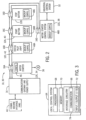
- FIG. 3 is a block diagram of an example local control system 64 used to perform one or more of the operations described herein.
- Each of the network devices 12 may include a respective local control system 64.
- the local control system 64 may include a communication component 66, a processor 68, a memory 70, input/output (I/O) ports 72, or the like.
- the communication component 66 may be a wireless or wired communication component that may facilitate communication between the industrial automation components, the industrial control system, and other communication capable devices. Although depicted as coupled to other components of the industrial control system, it should be understood that one or more local control systems 64 may be associated with any component of the industrial control system.
- the communication component 66 and the I/O ports 72 may be considered interface circuitry 74.
- the processor 68 may be any type of computer processor or microprocessor capable of executing computer-executable code.
- the processor 68 may also include multiple processors that may perform the operations described below.
- the memory 70 may be any suitable article of manufacture that serves as media to store processor-executable code, data, or the like. These articles of manufacture may represent computer-readable media (e.g., any suitable form of memory or storage) that may store the processor-executable code used by the processor 68 to perform the presently disclosed techniques.
- the processor 68 may execute software applications that include programs that enable a user to track and/or monitor operations of the industrial automation components via a local or remote communication link.
- the memory 70 may also store the data, analysis of the data, the software applications, and the like.
- the memory 70 may represent non-transitory computer-readable media (e.g., any suitable form of memory or storage) that may store the processor-executable code used by the processor 68 to perform various techniques described herein.
- the memory 70 may include a software application executed by the processor 68 and used to monitor, control, access, or view industrial automation equipment.
- the memory 70 may be used to store the device configuration file 46 or the backup device configuration file 48.
- the I/O ports 72 may be interfaces that may couple to other peripheral components such as input devices, sensors, I/O modules, and the like. I/O ports 72 may enable the local control system 64 to communicate with the industrial automation equipment or other devices in the industrial automation system.
- the local control system 64 includes and/or couples to various other sensors that may provide additional data related to an ambient environment of the network devices 12 and/or the operation of the industrial automation system.
- the other sensors may include an accelerometer, a gas (e.g., smoke, carbon monoxide) sensor, or the like.
- FIG. 4 is a block diagram representation of a state of the P-P network 10 after a device replacement operation.
- each of the network devices 12 may communicate (via paths 84) with each other.
- the network device 12A may transmit a message to the network device 12E that indicates a start instruction.
- the network device 12E may transmit a message to the network device 12C that indicates a motor load state.
- One or more of the network devices 12 may intercommunicate via sub-networks (subnets) of a communication network 86.
- the communication network 86 may be a smart wire configuration that enables the network devices 12 to couple to the communication network 86 at the input/output circuitry 16. Examples of the smart wire configuration may be shown via FIG. 8 , FIG. 9 , FIG. 10A , and/or FIG. 10B .
- Each of the network devices 12 may transmit or receive messages via subnets of the communication network 86.
- a subnet may guide transmission of data from the network device 12E to the network device 12C and/or from the network device 12A to the network device 12E.
- Subnets may be logically separated channels of the communication network 86, such that a same network may transmit data via the respective subnets without interruption to simultaneous transmissions.
- the communication network 86 may be of any suitable network, including wireless networks or wired networks, such as an Ethernet-based network.
- Each network device 12 may be considered a transmitting device and/or a receiving device. Some of the network devices 12 may operate as both a transmitting and a receiving device.
- the network devices 12 may transmit messages via respective subnets without assistance, or without being in response to a control signal from, an intermediary control system. To do so, the network device 12 may reference the device configuration file 46 stored in the memory 70 to determine which subnet to use to transmit a generated message.
- the network device 12E may reference its own device configuration file 46 to determine which subnet and which other of the networked devices 12 to send the generated message.
- Subnet definitions may be based at least in part on what operation was used to determine the data for the generated message. In this way different operations of the same network device 12 may use different subnets to transmit data. Adjacent devices may also be bypassed during data transmissions using the subnets since the data may be transmitted through the input/output circuitry 16 without being received at the within the network device 12.
- the network device 12 may use one or more identifiers included with the generated message to indicate to routing circuitry and/or to intercommunicating network devices an intended destination of the message (e.g., data endpoint) and through which subnet to transmit the message.
- Messages transmitted between a first network device 12 and a second network device 12 via a first subnet may not be interrupted by a message transmission between a third network device 12 and a fourth network device 12 via a second subnet since the communications may be separated by logical divisions according to the subnets.
- a message transmitted via subnet between network device 12A and network device 12E is not interrupted by a message transmitted between network device 12A and network device 12B and/or between network device 12C and network device 12E.
- Communicating via subnets may improve communication network operation by permitting one or more network devices 12 to intercommunicate without use of an intermediary control system to manage the communications.
- the device configuration file 46 may assign a network device to a subnet. In this way, two network devices 12 assigned to the same subnet may intercommunicate via the subnet without communicating via an additional subnet. Each network device 12 may communicate via a variety of subnets that connect one or more network devices 12. For example, the network device 12E may communicate with the network device 12A through a first subset and may communicate with the network device 12B through a second subnet without use of an intermediary control system to manage the data transmissions.
- a message generated by a network device 12 may be identified via a header before or after payload data of the message (e.g., sensing data, control operation, status).
- the header may include data regarding an originating network device 12 of the message, a destination of the message and a subnet through which to transmit the message
- Routing circuitry such as routing circuitry of the P-P network 10 and/or of the input/output circuitry 16, may interpret the header to determine how to transmit the message through the communication network, and, in particular, the subnet through which to transmit the message. Since subnet definitions may be included in a device configuration file, loading the device configuration file to configure a device of the peer-to-peer communication network may initialize and set (e.g., establish, logically define) communication pathways between the network devices 12.
- a network device 12 is to be replaced. This is represented in FIG. 4 as the network device 12F being replaced by the network device 12E.
- a device configuration file 46 defining the operation of the network device 12F may be stored on to the network device 12E.
- the network devices 12A, 12B, 12C, 12D may automatically identify when the network device 12F is replaced and may automatically transmit a backup device configuration file 48 to the replacement network device 12E without operator intervention or intermediary control system intervention.
- the network devices 12A, 12B, 12C, 12D may determine when one of the other network devices 12F is online or offline by performing detection operations as briefly mentioned above. Detection operations may include each of the network devices 12 broadcasting a signal particularly assigned to the respective network device 12 to be monitored, such that when a threshold number of signals are missed or not detected, a respective of the network devices 12 may be identified as offline or missing.
- the network device 12A may transmit a signal to the network device 12E at a regular or equal time interval.
- the network device 12E may monitor for the signal and if the time interval were to pass without the network device 12E receiving the signal, a count may be adjusted (e.g., incremented, decremented) to reflect the missed signal.
- the network device 12E may determine the network device 12A to be offline or missing.
- a continuous status signal may be transmitted to the P-P network 10 by each of the network devices 12, such that when one of the continuous status signals disappears, each of the other network devices 12 that are still online are able to determine which of the network devices 12 went offline.
- the network device 12A storing a backup device configuration file 48 may try to transmit the backup device configuration file 48 to the replacement network device 12E. If that transmission is incomplete or unable to happen, a next network device 12, such as the network device 12B, may try to transmit the backup device configuration file 48 to the replacement network device 12E. Attempting to transmit the backup device configuration file 48 may be repeated until a network device 12 having the appropriate backup device configuration file 48 completes the transmission.
- each network device 12 of the P-P network 10 may perform the self-healing operations.
- network device 12A may store a device configuration file 46 defining operation of the network device 12A, in addition to one or more other backup device configuration files 48 for other network devices 12 of the network. This may apply to each network device 12 of the P-P network 10.
- Each backup device configuration file 48 may include information used by the network device 12 to perform control operations and/or to intercommunicate via the P-P network 10.
- the backup device configuration file 48 may mirror a device configuration file 46 for a particular origin device (e.g., network device 12 storing the backed up and original device configuration file 46). Since a device configuration file 46 stores information associated with operations of the network device 12, the device configuration file 46, and thus the backup device configuration file 48, may include an origin device configuration identifier, origin device P-P network configuration data, and/or an origin device P-P network configuration data cyclic redundancy check value (CRC value).
- CRC value cyclic redundancy check value
- the origin device configuration identifier may include a device address, a position identifier, and/or a device product key.
- the device address may be a logical address used to identify the originating network device 12 for the purposes of message transmission. In this way, the device address may be interpretable by the communication network 86, such as via routers or routing circuitry of the communication network 86.
- the position identifier may identify a logical position relative to other network devices 12. For example, the position identifier of network device 12A may indicate numerically that the network device 12A is adjacent to network device 12B and network device 12E.
- the device product key may identify the particular network device 12 from a perspective of manufacturing.
- the device product key of the network device 12A may indicate a model, make, year manufactured, and/or operational features of the network device 12A and, in some cases, may differentiate the network device 12A from a similarly manufactured network device.
- the origin device configuration identifier may enable the network devices 12 to identify the origin device corresponding to the device configuration file 46.
- the origin device configuration identifier may be used to match a new device to stored backup device configuration file 48 via matching of device product keys.
- the new device may be an unconfigured network device. When the new device is matched to a backup device configuration file 48, one of the network devices 12 may transmit the backup device configuration file 48 to the new device to bring the new device online (e.g., to turn the new device into a network device 12).
- the backup device configuration file 48 may also include origin device P-P network configuration data.
- the origin device P-P network configuration data may define processing instructions, settings, operating ranges, indications of connections to other components within the industrial automation system, or the like, and may be used to customize an operation of the network device 12 to the P-P network 10 and/or to the industrial automation system 30.
- the origin device P-P network configuration data may define at what frequency a network device 12 is to sample information, communicate statuses with other network devices 12, update an output from the I/O ports 72, such as a control signal to perform an operation or to communication a status, or the like.
- the backup device configuration file 48 may also include the CRC value.
- the CRC value may be generated when an encryption and/or encoding of the backup device configuration file 48 occurs, such as in preparation for transmission via the P-P network 10.
- the CRC value may be one or more bits, or character strings, included with a device configuration file 46 and/or a backup device configuration file 48.
- the CRC value may be used to verify whether a data transmission involving the device configuration file 46 and/or the backup device configuration file 48 is secure and/or performed without comprise to the original data of the device configuration file 46 and/or the backup device configuration file 48 (e.g., was transmitted without unintentional or intentional manipulation). Encryption and/or security operations may use the CRC value when verifying whether unauthorized access attempts are performed to the P-P network 10 and/or any of the network devices 12.
- the new device may retrieve the backup device configuration file 48 from the network device 12. For example, the new device may send a request to the network devices 12 in the P-P network 10 with the device configuration identifier of the new device. The first network device 12 that has a matching backup device configuration file 48 that includes an origin device configuration identifier that matches the device configuration identifier may report back to the new device. The new device may receive the backup device configuration file 48 from the network device 12 with the matched origin device configuration identifier. Then, the new device may store the backup device configuration file 48 as the device configuration file 46.
- Determining which network device 12 is to transmit the backup device configuration file 48 may be based on a date and/or time of the data stored, ongoing operations, a physical proximity, a logical proximity, or the like.
- the backup device configuration file 48 that corresponds to a most recent update may be used to restore the configuration file to the new device.
- a candidate restoring network device 12 involved in ongoing operations may not be selected to transmit the backup device configuration file 48.
- the network device 12C or the network device 12D may transmit the backup device configuration file 48 to the network device 12. This may reduce delays caused by waiting for a network device 12 to be available to transmit a backup device configuration file 48.
- the network devices 12 may determine a physical distance associated with communication channels of the P-P network 10. The physical distance may be determined based on a difference in locations between network devices 12. For example, a distance may be determined between the new network device 12E and a candidate restoring network device 12A (e.g., one of the network devices 12A, 12B, 12C, 12D being considered to become the restoring network device 12). The pair of devices that has the lowest relative physical distance may be selected (e.g., as a way to lower overall communication time or reduce transmission latencies).
- a similar comparison to physical proximity may be performed but via a comparison that uses logical locations and/or a logical proximity between the new device and the candidate restoring network device 12.
- the network device 12A may determine that the network device 12B has lost the device configuration file 46.
- the network device 12A may determine which of the network devices 12 is of closer logical proximity to the network device 12B.
- the network device 12A may determine that the network device 12D is logically closer to the network device 12B than the network device 12A.
- the determination of logical proximity may include evaluating subnet routings between network devices 12 and/or anticipated memory retrieval latencies to determine a more efficient logical transmission route relative to possible logical transmission routes.
- the network devices 12 may use combination of conditions (e.g., physical proximity, a logical proximity, a date and/or time of the data stored, ongoing operations) to identify the restoring network device 12. For example, a backup device configuration file 48 corresponding to the most recently obtained or stored data that is also physically closest to the new network device 12E may be used to restore the configuration to the new device, such as the backup device configuration file 48 stored in the network device 12A. In this way, a combination of tradeoffs may be considered when determining the identifying network device 12.
- conditions e.g., physical proximity, a logical proximity, a date and/or time of the data stored, ongoing operations
- Each of the network devices 12 may be a static transmitting device, a static receiving device, a dynamic transmitting device, a dynamic receiving device, or any combination thereof.
- a static transmitting device may generate a message that includes a option selected from a fixed set of options (e.g., on or off, high or low, yes or no), while a static receiving device may interpret a message to generate an output from a fixed set of options.
- Each static device may have a fixed set of data options, where the data may be binary data and/or analog data.
- a dynamic transmitting device may generate a message that includes data from a variable set of options (e.g., a value that changes in response to an input not part of a defined set of options), while a dynamic receiving device may receive one or more messages and use data of the messages to generate an output.
- a variable set of options e.g., a value that changes in response to an input not part of a defined set of options
- Each dynamic device may have a dynamically generated variable set of data options according to a specific operation.
- the data associated with the dynamic device may be binary or analog.
- network device 12A may be a static transmitting device since the network device 12A may generate a message indicating when the start button 40 is pressed but may not generate a message indicating intermediating positions of the start button 40 or indicating at what relative location the button is pressed.
- a network device 12 that includes a pressure sensor may generate a message that includes data corresponding to a non-binary set of options since the pressure sensor may transmit a message based on a relative indication of pressure within a vessel, and not necessarily in response to pressure being present in the vessel in general.
- a communicative coupling between one or more static transmitting devices and one or more static receiving devices may be made via a hardcoded local control and/or via a programmable logic control, as defined via the device configuration file 46.
- the hardcoded local control may include use a hardcoded subnet definition defining the transmitting devices and defining the receiving devices (e.g., hardcoded in a device configuration file 46). Hardcoded local control may use physical couplings to define sub-networks and/or transmission pathways.
- the programmable logic control may include one or more determinations to set a receiving network device 12. For example, in a programmable logic control system, a transmitting network device 12 may determine to which receiving device to transmit based at least in part on the generated message and/or generated data before transmission.
- the device configuration file 46 specifics a coordinated local control system for controlling communications between any device type, such as between dynamic transmitting device and static receiving devices, dynamic transmitting device and dynamic receiving devices, or the like.
- network devices 12 may process inputs and/or outputs before transmitting data via the P-P network 10.
- a first network device 12 may generate an analog data-based status to be transmitted to a second network device 12 for interpretation and use in controlling a motor speed but the transmission may include a third network device 12 that changes a color of a light proportional to the value of the analog data-based status from the first network device 12 before transmission onto the second network device 12.
- the network device 12D may generate a message that a second network device 12E uses to determine a third of the network devices 12 to transmit the message.
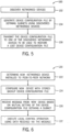
- FIG. 5 is a flowchart of a method 100 for transmitting a device configuration file 46 via the P-P network 10.
- the method 100 is described as being performed by a network device 12, it should be understood that the method 100 may be performed by any suitable component of the P-P network 10.
- any network device 12, the industrial control system 32, or any suitable processing circuitry may perform some or all of the method 100.
- the method 100 may be performed to initialize a network device 12. As described below, particular network devices 12 are called out in the descriptions of the method 100. It is noted that this is done for ease of discussion, and in an actual implementation, the operations described herein may be interchangeable between the network devices 12.
- the network device 12F may discover other network devices 12A, 12B, 12C, 12D present on the P-P network 10.
- One or more of the network devices 12 that operate as part of the P-P network 10 may be considered a P-P data endpoint.
- the network device 12F may perform a search of the P-P network 10 to detect the P-P data endpoints.
- the communicative couplings of the P-P network 10 may enable the network device 12F to detect connection statuses of the other network devices 12A, 12B, 12C, 12D (e.g., whether or not the other network devices 12A, 12B, 12C, 12D are coupled and/or communicating via the P-P network 10).
- the network device 12F may generate a device configuration file 46 at least in part by defining subnets. Based on control operations to be performed by the network device 12F and the discovered network devices 12A, 12B, 12C, 12D, the network device 12F may determine which of the discovered network devices 12A, 12B, 12C, 12D that data generated by the network device 12F is to be transmitted, and thus which groups of network devices 12A, 12B, 12C, 12D are associated with each other or with the network device 12F. In this way, the network device 12F may define a subnet between receiving network devices 12 and transmitting network devices 12 determined to be associated with each other.
- the device configuration file 46 may be a configuration file initially installed on the network device 12F that the network device 12F updates to include definitions of the subnets (e.g., at a later time than initial installation) and/or updates to one or more settings.
- the network device 12F may transmit the device configuration file 46 to one or more other network devices 12A, 12B, 12C, 12D as the backup device configuration file 48.
- the backup device configuration file 48 may be used to restore an original configuration to the network device 12F in the event that the network device 12F is replaced with a new device (presumably a new device without the original device configuration file 46 stored).
- one of the other network devices 12A, 12B, 12C, 12D may detect the replacement and facilitate the transmission of the backup device configuration file 48 to restore a previous operational capacity of the replaced network device 12F to a new network device 12E. This process is described by FIG. 6 .
- FIG. 6 is a flowchart of a method 120 for performing a replacement of a device configuration file 46.
- the method 120 may be performed by any suitable component of the P-P network 10.
- any network device 12, the industrial control system 32, or any suitable processing circuitry may perform some or all of the method 120.
- the method 120 may be performed in response to the network device 12 detecting a new device being coupled to the P-P network 10.
- the network device 12 may detect a new device being hot-swapped, or physically replaced while the P-P network 10 remains online.
- particular network devices 12 are called out in the descriptions of the method 120. It is noted that this is done for ease of discussion, and in an actual implementation, the operations described herein may be interchangeable between the network devices 12.
- one of the network devices 12A, 12B, 12C, 12D may determine that a new network device 12E is installed into the P-P network 10.
- a newly installed network device 12E may broadcast a signal via the P-P network 10 for the other network devices 12A, 12B, 12C, 12D to detect and interpret as a notification message from the newly installed network device 12E confirming installation.
- one of the network devices 12A, 12B, 12C, 12D may determine that a new network device 12E is installed into the P-P network 10 by polling the P-P network 10 to detect when the network device 12E is installed.
- Signals used to poll the P-P network 10 may be transmitted by one or more of the network devices 12A, 12B, 12C, 12D on a periodic frequency to regularly check for newly installed devices
- the new network device 12E may not be initially able to communicate via the P-P network 10
- the new network device 12E may be physically coupled to the P-P network 10.
- network device 12C is described below as detecting the installation of the network device 12E.
- the network device 12C may send the backup device configuration file 48 to the new network device 12E.
- the backup device configuration file 48 corresponds to a device configuration file 46 of the previously installed network device 12F (e.g., the network device 12 that was replaced).
- the backup device configuration file 48 may restore settings, operations, and/or thresholds to be referenced by the new network device 12E when performing control operations (e.g., executing local control operations to generate an output from the new network device 12E in response to an input into the new network device 12E).
- the backup device configuration file 48 may also define a subnet to which certain outputs are to be communicated on by the new network device 12E.
- the network device 12C may receive a message from the new network device 12E based at least in part on a mutual setting of the backup device configuration file 48 defining a subnet (e.g., now stored as the device configuration file 46 within the new network device 12E).
- the mutual setting may correspond to a type of device to be a data endpoint for data generated by a particular control operation.
- the network device 12C may be defined as a data endpoint for a control operation of the new network device 12E.
- the new network device 12E may transmit data generated via the control operation to the network device 12C, when the data is ready for transmission in a message.
- the network device 12C may execute a local control operation using the data received via the message from the new network device 12E. In this way, the network device 12C performs an operation based on results from an operation of the new network device 12E. For example, the new network device 12E may output a status indicating a load is powered on and the network device 12C may cause a light-emitting device to emit light in response to receiving data indicating that the load is powered on from the new network device 12C.
- a variety of suitable control operations may be performed by one or more network devices 12 in response to various inputs and/or outputs from the other network devices 12.
- the P-P network 10 may include an intermediary control system.
- the intermediary control system may manage communications between network devices 12.
- the network device 12 may be able to perform autonomously without instruction from the intermediary control system at least in part by using the systems and methods described herein.
- the P-P network 10 may be resilient and may continue to operate using subnet communications between the network devices 12 and/or may continue to operate in response to messages generated via a transmitting network device 12.
- control mode e.g., intermediary control system operational mode versus local control operational mode via the network devices 12
- the control mode may be either selected by an operator (e.g., a mode manual selection) or may be automatically selected by the P-P network 10 (e.g., mode automatic selection) in response to the network devices 12 detecting an offline or unusable intermediary control system.
- the intermediary control system operational mode or the local control operational mode may be selected via a control signal configurable to switch a switching device, thereby causing the P-P network 10 to enter the operational mode.
- the operational mode of the P-P network 10 may be set via an internal parameter controlled by software of the industrial control system 32.
- a switching condition may be a network status.
- the P-P network 10 may be switched into the mode automatic selection in response to a status of a communicative coupling between one or more network devices 12 and the intermediary control system.
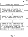
- FIG. 7 is a flowchart of a method 140 for generating a device configuration file 46 and a backup device configuration file 48 using an intermediary control system.
- the method 140 is described as being performed by an intermediary control system, it should be understood that some or all the method 140 may be performed by any suitable component of the P-P network 10, including a network device 12 facilitating the generation of a device configuration file 46 or a backup device configuration file 48.
- the method 140 may be performed in response to one of the network devices 12, industrial control system 32, the intermediary control system, or any suitable processing device, detecting a new device being coupled to the P-P network 10.
- the intermediary control system may detect a new device being hot-swapped, or physically replaced while the P-P network 10 remains online.
- particular network devices 12 are called out in the descriptions of the method 140. It is noted that this is done for ease of discussion, and in an actual implementation, the operations described herein may be interchangeable between the network devices 12.
- the intermediary control system may discover data endpoints.
- the intermediary control system may use test control signals to track which network devices 12 are coupled to the P-P network 10.
- the intermediary control system may determine which network devices 12 are adjacent to each other and may use that information when pairing a transmitting network device 12 with a receiving network device 12.
- the intermediary control system may generate a device configuration file 46 by associating the data endpoints based on a local control application.
- the intermediary control system may store or may retrieve the local control application from memory 70.
- the local control application may include control and/or operational definitions for each of the network devices 12.
- the control and/or operational definitions may include definitions for operating frequencies, transmission protocols, conversion polices, or the like, to enable communication between two network devices 12 and the P-P network 10.
- the network device 12A may operate according to operational definitions of a corresponding local control application.
- the intermediary control system may generate the device configuration file 46 to include starting points (e.g., device origins) and endpoints for each local control application of the network device 12A.
- the local control application may define a particular frequency at which the network device 12A is to expect to receive data from the network device 12D, a particular frequency at which the network device 12A is to poll its own sensing devices to receive generated sensing data, and a particular frequency at which the network device 12A is to compare data from the network device 12A and its own generated sensing data to determine the control signal output to the network device 12E.
- the starting points of the local control application include the network device 12D and the network device 12A, while the data endpoint of the local control application is the network device 12E.
- the intermediary control system may, for example, determine a control operation to be performed by the network device 12A based on a local control application.
- the intermediary control system may determine from the local control application a type of device to receive data that is going to be generated and transmitted by the network device 12A.
- the local control application may define the type of device using the device product key (or a subset of the device product key, such as a string corresponding to a model number or part type).
- the intermediary control system may determine which of the network devices 12 corresponds to the type of device. In this example, the intermediary control system may determine that the network device 12E matches the type of device. This may be determined by matching the type of device to one or more of the device product keys of the network devices 12.
- the intermediary control system may update a device configuration file for the network device 12E to reflect a data endpoint pairing between the network device 12E and the network device 12A for a particular data generation operation.
- the network device 12E and the network device 12A may be defined to intercommunicate via a subnet coupling since the two network devices 12 are associated with a data endpoint pairing.
- the network device 12E may reference the data endpoint pairing to determine the subnet through which to transmit data generated via the data generation operation.
- the intermediary control system may transmit the device configuration file 46 to a first network device for use in the local control application.
- the network device 12 may configure certain settings, thresholds, ranges, subnets, or the like, defined by the device configuration file 46. After configuration, the network device 12 may reference the information of the device configuration file 46 when determining to perform a local control operation and/or while performing the local control operation.
- the intermediary control system may transmit the device configuration file 46 as a backup device configuration file 48 to a second network device of the network devices 12 for use in automatically reconfiguring a replacement of the network device 12 that receives the device configuration file 46.
- the intermediary control system may transmit the device configuration file 46 to the network device 12A and the backup device configuration file 48 to the network device 12B.
- the intermediary control system may transmit the backup device configuration file to the network device 12B, 12C, 12D, and 12E in response to generating the device configuration file 46 to the network device 12A.
- each of the network devices 12 may store a backup device configuration file 48 for each of the other network devices 12. Transmission of the device configuration file 46 and the backup device configuration file 48 may happen at the same time, at a partially overlapping time, during different time periods, or any combination thereof.
- the original device configuration file is generated by the P-P manager software 20.
- the P-P manager software 20 may perform the discovery operation of block 102 of the method 100, and update the original device configuration file with the subnet definitions as performed in the operations of block 104.
- block 106 of the method 100 may refer to, in these cases, the P-P manager software 20 transmitting the updated original device configuration file to a first network device 12 as the device configuration file 46 and to other network devices 12 as the backup device configuration file 48.
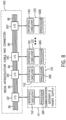
- FIG. 8 is a block diagram of the communication network in a smart wire configuration that enables each of the network devices 12 to directly communicate with each other without intervention or control by a larger control system.
- Each network device 12 may generate messages based on operations performed by the processors 68.
- a network device 12 may transmit the message to another of the network devices 12 via a smart wire media infrastructure 160 that includes the input/output circuitry 16 and the communication network 86.
- each of the input/output circuitry 16 couples to the smart wire media infrastructure 160 via seven pins and seven couplings, however it is noted that any suitable number of couplings may be used to transmit data between the network devices 16.
- the interface circuitry 74 may couple to the input/output circuitry 16 using eight pins or eight couplings.
- the network devices 12 may transmit messages through the smart wire media infrastructure 160.
- the messages transmitted may be passed through one or more input/output circuitries 16 before reaching a destination input/output circuitry 16.
- input/output circuitry 16E may pass a message to the input/output circuitry 16C from the communication gateway and power supply 14 without alteration.
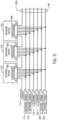
- FIG. 9 is a block diagram of example logical couplings of the smart wire media infrastructure 160A.
- Each network device 12 may couple to the other network devices 12 via the communication network 86.
- Control signals that enable communication between the network devices 12 include a select signal 172, a network power positive signal 174 and negative signal 176, an Ethernet positive signal 178 and negative signal 180, and a control power positive signal 182 and negative signal 184.
- the select signal 172 may be a sequential service delivery signal that enables the network devices 12 to transmit messages sequentially through the other network devices 12.
- the network power positive signal 174 and negative signal 176 may delivery power to each of the network devices 12 and/or to the network components of each network device 12 from a power supply or tapped connection off of another electrical coupling.
- the Ethernet positive signal 178 and negative signal 180 provide for network communication functionality.
- the Ethernet positive signal 178 and negative signal 180 may be a part of a bus and/or multi-drop topology, a topology where multiple data endpoints couple to a same communication bus.
- the control power positive signal 182 and negative signal 184 may power an actuator (e.g., a contactor coil) for at least one of the network devices 12.
- An actuator may execute a control operation for the network device 12.
- a control operation of the network device 12E may including transmitting a control signal to the motor 36 to power on the motor 36 and an actuator of the network device 12E may close to initiate transmission of the control signal.
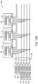
- FIG. 10A and FIG. 10B Several variations of the smart wire media infrastructure 160A are shown in FIG. 10A and FIG. 10B . While the smart wire media infrastructure 160A may use a seven-line, eight-pin connector to couple the network devices 12 to the communication network 86, FIG. 10A and FIG. 10B show that any suitable number of pins and lines may be used to provide a smart wire communication system.
- FIG. 10A is a block diagram of another example logical couplings of a smart wire media infrastructure 160B and FIG. 10B is a block diagram of an example logical couplings of a smart wire media infrastructure 160C.
- the smart wire media infrastructure 160B may be a five-line cable that uses six-pin connector circuitry to couple the network devices 12 to the communication network 86.
- the smart wire media infrastructure 160C may be a six-line cable that uses eight-pin connector circuitry to couple the network devices 12 to the communication network 86.
- the smart wire media infrastructure 160B combines the network power positive signal 174 and the Ethernet positive signal 178 into a same communicative coupling.
- the smart wire media infrastructure 160B also combines the network power negative signal 176 and the Ethernet negative signal 180 into a same communicative coupling. In this way. the network power and the Ethernet couplings may share a same pair of wires.
- the select signal 172 may be of a daisy chain configuration, where each network device 12 is coupled to the adjacent network devices 12.
- the smart wire media infrastructure 160C may daisy chain adjacent network devices 12 using the Ethernet positive signal 178 and the Ethernet negative signal 180.
- the Ethernet signals may transmit through respective switches 190 of the network devices that may control a timing used to transmit messages between network devices 12 via the Ethernet communicative couplings.
- the network power positive signal 174, network power negative signal 176, control power positive signal 182, and control power negative signal 184 of the smart wire media infrastructure 160C may operate similar to the same signals of the smart wire media infrastructure 160A.
- the network devices may intercommunicate independently of a control system via the peer-to-peer communication network. In this way, messages transmitted between the network devices may incur relatively less latencies and/or may transmit relatively faster since the network devices are not waiting for control signals from the control system to operate. Furthermore, network devices of the peer-to-peer network may backup device configuration files for the other network devices of the peer-to-peer network. If a network device were to lose a device configuration file, another network device of the peer-to-peer communication network may detect the loss and transmit a stored backup device configuration file to the network device.
Landscapes
- Engineering & Computer Science (AREA)
- Computer Networks & Wireless Communication (AREA)
- Signal Processing (AREA)
- Automation & Control Theory (AREA)
- Manufacturing & Machinery (AREA)
- General Physics & Mathematics (AREA)
- Physics & Mathematics (AREA)
- General Engineering & Computer Science (AREA)
- Quality & Reliability (AREA)
- Human Computer Interaction (AREA)
- Medical Informatics (AREA)
- Computing Systems (AREA)
- General Health & Medical Sciences (AREA)
- Health & Medical Sciences (AREA)
- Computer And Data Communications (AREA)
- Information Retrieval, Db Structures And Fs Structures Therefor (AREA)
- Information Transfer Between Computers (AREA)
Claims (15)
- System, das umfasst:eine erste Netzwerk-Vorrichtung (12E), die so konfiguriert ist, dass sie einen Betrieb einer Industrieautomations-Vorrichtung auf Basis einer Einstellung der Vorrichtungs-Konfigurationsdatei (48) steuert; sowieeine zweite Netzwerk-Vorrichtung (12A), die so konfiguriert ist, dass sie mit der ersten Netzwerk-Vorrichtung (12E) direkt kommunizierend über ein P-P-Kommunikationsnetz (peer-to-peer communication network) (10) für ein Industrieautomations-System gekoppelt ist,wobei die zweite Netzwerk-Vorrichtung (12A) eine Backup-Vorrichtungs-Konfigurationsdatei (48) umfasst, die der Vorrichtungs-Konfigurationsdatei (46) entspricht,wobei die zweite Netzwerk-Vorrichtung (12A) so konfiguriert ist, dass sie in Reaktion darauf, dass der ersten Netzwerk-Vorrichtung (12E) die Vorrichtungs-Konfigurationsdatei (46) fehlt, die Backup-Vorrichtungs-Konfigurationsdatei (48) zu der ersten Netzwerk-Vorrichtung (12E) sendet,wobei das P-P-Kommunikationsnetz (10) so konfiguriert ist, dass es die erste Netzwerk-Vorrichtung (12E) und die zweite Netzwerk-Vorrichtung (12A) über ein Teilnetz koppelt, undwobei die Vorrichtungs-Konfigurationsdatei (46) einen Daten-Endpunkt mit dem Teilnetz definiert, wobei die erste Netzwerk-Vorrichtung so konfiguriert ist, dass sie in Reaktion auf eine durch die Backup-Vorrichtungs-Konfigurationsdatei (48) definierte Einstellung eine Operation innerhalb des Industrieautomations-Systems durchführt.
- System nach Anspruch 1,
wobei das Teilnetz mit einer logischen Definition eines oder mehrerer Kommunikationskanals/-kanäle innerhalb des P-P-Kommunikationsnetzes (10) verbunden ist. - System nach Anspruch 1,
wobei die erste Netzwerk-Vorrichtung (12E) so konfiguriert ist, dass sie in Reaktion darauf, dass die erste Netzwerk-Vorrichtung (12E) die Vorrichtungs-Konfigurationsdatei (46) erzeugt, die Backup-Vorrichtungs-Konfigurationsdatei (48), die der Vorrichtungs-Konfigurationsdatei (46) entspricht, automatisch zu der zweiten Netzwerk-Vorrichtung (12A) sendet. - System nach Anspruch 1 oder 3,
wobei die erste Netzwerk-Vorrichtung (12E) so konfiguriert ist, dass sie in Reaktion darauf, dass die erste Netzwerk-Vorrichtung (12E) die Vorrichtungs-Konfigurationsdatei (48) erzeugt, die Backup-Vorrichtungs-Konfigurationsdatei (48), die der Vorrichtungs-Konfigurationsdatei (46) entspricht, automatisch über eine Smart-Wire-Konfiguration (160A; 160B; 160C) zu einer Vielzahl von Netzwerk-Vorrichtungen (12A, 12B, 12D) sendet. - System nach einem der Ansprüche 1, 3, oder 4,
wobei die zweite Netzwerk-Vorrichtung (12A) so konfiguriert ist, dass sie auf Basis von Daten, die anzeigen, dass die erste Netzwerk-Vorrichtung (12E) zu dem P-P-Kommunikationsnetz (10) hinzugefügt wird, erfasst, dass der ersten Netzwerk-Vorrichtung (12E) die Vorrichtungs-Konfigurationsdatei (68) fehlt. - Verfahren (120), das umfasst:Erfassen (122), dass einer zweiten Netzwerk-Vorrichtung (12E) eine Vorrichtungs-Konfigurationsdatei (46) fehlt, über eine erste Netzwerk-Vorrichtung (12A),wobei die erste Netzwerk-Vorrichtung (12A) eine Backup-Vorrichtungs-Konfigurationsdatei (48) umfasst, die der Vorrichtungs-Konfigurationsdatei (46) entspricht,die erste Netzwerk-Vorrichtung (12A) so konfiguriert ist, dass sie über ein P-P-Kommunikationsnetz (peer-to-peer communication network) (10) für ein Industrieautomations-System direkt mit der zweiten Netzwerk-Vorrichtung (12A) kommuniziert,wobei das P-P-Kommunikationsnetz (10) so konfiguriert ist, dass es die zweite Netzwerk-Vorrichtung (12E) und die erste Netzwerk-Vorrichtung (12A) über ein Teilnetz koppelt, undwobei die Vorrichtungs-Konfigurationsdatei (46) einen mit dem Teilnetz verbundenen Daten-Endpunkt definiert; sowieSenden (124) einer Backup-Vorrichtungs-Konfigurationsdatei (48), die der Vorrichtungs-Konfigurationsdatei (46) entspricht, über die erste Netzwerk-Vorrichtung (12A) zu der zweiten Netzwerk-Vorrichtung (12E) in Reaktion darauf, dass erfasst wird, dass der zweiten Netzwerk-Vorrichtung die Vorrichtungs-Konfigurationsdatei (46) fehlt,
wobei die zweite Netzwerk-Vorrichtung (12E) so konfiguriert ist, dass sie in Reaktion auf eine durch die Backup-Vorrichtungs-Konfigurationsdatei (48) definierte Einstellung eine Operation innerhalb des Industrieautomations-Systems durchführt. - Verfahren nach Anspruch 6, das umfasst, dass über die erste Netzwerk-Vorrichtung (12A) die Backup-Vorrichtungs-Konfigurationsdatei (48) von der zweiten Netzwerk-Vorrichtung (12E) empfangen wird, nachdem die zweite Netzwerk-Vorrichtung (12E) die Vorrichtungs-Konfigurationsdatei (48) erzeugt hat.
- Verfahren nach Anspruch 6 oder 7, das Auswählen einer dritten Netzwerk-Vorrichtung aus einer Vielzahl von Netzwerkvorrichtungen (12B, 12C, 12D) über die erste Netzwerk-Vorrichtung (12A) auf Basis einer physischen Nähe der dritten Netzwerk-Vorrichtung relativ zu der zweiten Netzwerk-Vorrichtung (12E) umfasst, wobei bei dem Senden (124) der Backup-Vorrichtungs-Konfigurationsdatei (48) die in der dritten Netzwerk-Vorrichtung gespeicherte Backup-Vorrichtungs-Konfigurationsdatei (48) verwendet wird.
- Verfahren nach Anspruch 8, wobei Senden der Backup-Vorrichtungs-Konfigurationsdatei (48) zu der zweiten Netzwerk-Vorrichtung (12E) Identifizieren der zweiten Netzwerk-Vorrichtung (12A) aus einer Vielzahl von Netzwerk-Vorrichtungen (12A, 12B, 12C, 12D) auf Basis einer logischen Nähe der dritten Netzwerk-Vorrichtung relativ zu der zweiten Netzwerk-Vorrichtung umfasst.
- Verfahren nach einem der Ansprüche 6 bis 9, wobei Senden (124) der Backup-Vorrichtungs-Konfigurationsdatei (48) zu der zweiten Netzwerk-Vorrichtung (12E) Identifizieren der ersten Netzwerk-Vorrichtung (12A) aus einer Vielzahl von Netzwerk-Vorrichtungen (12A, 12B, 12C, 12D) auf Basis einer Zeit, die mit der in der ersten Netzwerk-Vorrichtung (12A) gespeicherten Backup-Vorrichtungs-Konfigurationsdatei (48) verknüpft ist, relativ zu einer Zeit umfasst, die mit dem Zeitpunkt verknüpft ist, zu dem jede einer Vielzahl zusätzlicher Backup-Vorrichtungs-Konfigurationsdateien an einer entsprechenden Netzwerk-Vorrichtung gespeichert wird.
- Verfahren nach einem der Ansprüche 6 bis 10, das Empfangen der Backup-Vorrichtungs-Konfigurationsdatei (48) über die erste Netzwerk-Vorrichtung (12A) von der zweiten Netzwerk-Vorrichtung (12E) über das Teilnetz umfasst.
- Verfahren nach einem der Ansprüche 6 bis 11, wobei Erfassen (122), dass der zweiten Netzwerk-Vorrichtung (12E) die Vorrichtungs-Konfigurationsdatei (46) fehlt, umfasst:Überwachen eines von der zweiten Netzwerk-Vorrichtung (12E) ausgegebenen Signals über die erste Netzwerk-Vorrichtung (12A); sowieErfassen, wann sich der Signalausgang ändert, über die erste Netzwerk-Vorrichtung (12A).
- Physisches nichtflüchtiges, computerlesbares Medium, das so konfiguriert ist, dass es Befehle speichert, die von einem Prozessor (68) einer elektronischen Vorrichtung ausgeführt werden können, und die, wenn sie von dem Prozessor ausgeführt werden, den Prozessor veranlassen, folgende Schritte durchzuführen:Entdecken (102) einer Vielzahl von Daten-Endpunkten, wobei jeder Daten-Endpunkt der Vielzahl von Daten-Endpunkten einer entsprechenden Netzwerk-Vorrichtung (12A, 12B, 12C, 12D) entspricht, die mit einer ersten Netzwerk-Vorrichtung (12F) über ein Teilnetz eines P-P-Kommunikationsnetzes (peer-to-peer communication network) (10) für ein Industrieautomations-System gekoppelt ist;Erzeugen (104) einer Vorrichtungs-Konfigurationsdatei (46) für die erste Netzwerk-Vorrichtung (12F) des P-P-Kommunikationsnetzes (10) auf Basis jeweiliger Daten-Endpunkte der Vielzahl mit der ersten Netzwerk-Vorrichtung (12E) verknüpfter Daten-Endpunkte, so dass die Vorrichtungs-Konfigurationsdatei (46) eine Definition des Teilnetzes einschließt, wobei die Vorrichtungs-Konfigurationsdatei des Weiteren eine Einstellung für die erste Netzwerk-Vorrichtung (12E) zum Steuern eines Betriebes einer Industrieautomations-Vorrichtung auf Basis der Einstellung der Vorrichtungs-Konfigurationsdatei (48) einschließt; undSenden der Vorrichtungs-Konfigurationsdatei zu wenigstens der ersten Netzwerk-Vorrichtung (12A) des P-P-Kommunikationsnetzes (10), wobei die Vorrichtungs-Konfigurationsdatei als eine Backup-Vorrichtungs-Konfigurationsdatei (48) zu verwenden ist, wenn der ersten Netzwerk-Vorrichtung (12E) die Vorrichtungs-Konfigurationsdatei fehlt, und die erste Netzwerk-Vorrichtung so konfiguriert ist, dass sie in Reaktion auf eine durch die Backup-Vorrichtungs-Konfigurationsdatei definierte Einstellung eine Operation innerhalb des Industrieautomations-Systems durchführt.
- Nichtflüchtiges computerlesbares Medium nach Anspruch 13, das:Befehle umfasst, die den Prozessor veranlassen, die Vielzahl von Daten-Endpunkten wenigstens teilweise durch Senden einer Vielzahl von Testsignalen über das P-P-Kommunikationsnetz (10) zu entdecken;Befehle umfasst, die den Prozessor veranlassen, die Vorrichtungs-Konfigurationsdatei (46) zu einer Vielzahl von Netzwerk-Vorrichtungen (12A, 12B, 12C, 12D) zu senden, die die zweite Netzwerk-Vorrichtung (12A) umfassen; oder/undBefehle umfasst, die den Prozessor veranlassen, die zweite Netzwerk-Vorrichtung aus der Vielzahl von Netzwerk-Vorrichtungen wenigstens teilweise auf Basis einer logischen Nähe der zweiten Netzwerk-Vorrichtung relativ zu der ersten Netzwerk-Vorrichtung, einer physischen Nähe der zweiten Netzwerk-Vorrichtung zu der ersten Netzwerk-Vorrichtung, eines Zeitpunktes, zu dem die Backup-Vorrichtungs-Konfigurationsdatei erzeugt wurde, oder einer beliebigen Kombination daraus zu identifizieren.
- Nichtflüchtiges computerlesbares Medium nach Anspruch 13 oder 14, wobei die Befehle, die den Prozessor veranlassen, eine Vorrichtungs-Konfigurationsdatei (46) zu erzeugen, Befehle umfassen, die den Prozessor veranlassen, folgende Schritte durchzuführen:Bestimmen einer von der ersten Netzwerk-Vorrichtung (12E) durchzuführenden Steuerungs-Operation;Bestimmen eines Typs von Vorrichtung zum Empfangen von Daten von der ersten Netzwerk-Vorrichtung;Bestimmen einer dritten Netzwerk-Vorrichtung des P-P-Kommunikationsnetzes (10), die dem Typ von Vorrichtung entspricht;Verknüpfen der dritten Netzwerk-Vorrichtung und der ersten Netzwerk-Vorrichtung zu einem Paar von Daten-Endpunkten, die so konfiguriert sind, dass sie über eine Teilnetz-Kopplung auf Basis der Vorrichtungs-Konfigurationsdatei miteinander kommunizieren; undAktualisieren der Vorrichtungs-Konfigurationsdatei, um die Teilnetz-Kopplung für Bezugnahme durch die erste Netzwerk-Vorrichtung zu definieren, nachdem die erste Netzwerk-Vorrichtung mit der Vorrichtungs-Konfigurationsdatei konfiguriert wurde.
Applications Claiming Priority (1)
| Application Number | Priority Date | Filing Date | Title |
|---|---|---|---|
| US16/580,995 US11036209B2 (en) | 2019-09-24 | 2019-09-24 | Peer-level control of industrial automation system components |
Publications (3)
| Publication Number | Publication Date |
|---|---|
| EP3799394A2 EP3799394A2 (de) | 2021-03-31 |
| EP3799394A3 EP3799394A3 (de) | 2021-05-19 |
| EP3799394B1 true EP3799394B1 (de) | 2023-07-12 |
Family
ID=72139460
Family Applications (1)
| Application Number | Title | Priority Date | Filing Date |
|---|---|---|---|
| EP20191255.7A Active EP3799394B1 (de) | 2019-09-24 | 2020-08-17 | Peer-überwachung von bauteilen industrieller automatisierungssysteme |
Country Status (2)
| Country | Link |
|---|---|
| US (2) | US11036209B2 (de) |
| EP (1) | EP3799394B1 (de) |
Families Citing this family (8)
| Publication number | Priority date | Publication date | Assignee | Title |
|---|---|---|---|---|
| US11487264B2 (en) * | 2018-08-10 | 2022-11-01 | Arvus Tecnologia Ltda. | Sensor and actuator based lifecycle monitoring of machines performing automated machine tasks |
| US11036209B2 (en) * | 2019-09-24 | 2021-06-15 | Rockwell Automation Technologies, Inc. | Peer-level control of industrial automation system components |
| US12099347B2 (en) | 2021-09-24 | 2024-09-24 | Rockwell Automation Technologies, Inc. | Option card for facilitating communication in drive applications |
| US12147213B2 (en) | 2021-09-24 | 2024-11-19 | Rockwell Automation Technologies, Inc. | Employing single pair ethernet for zoned safety in drive applications |
| US12067299B2 (en) | 2021-09-24 | 2024-08-20 | Rockwell Automation Technologies, Inc. | Multi-drive usage based on single pair ethernet |
| US12374886B2 (en) * | 2023-08-08 | 2025-07-29 | Energy Vault, Inc. | Systems and methods for fault tolerant energy management systems configured to manage heterogeneous power plants |
| US12355236B2 (en) | 2023-08-08 | 2025-07-08 | Energy Vault, Inc. | Systems and methods for fault tolerant energy management systems configured to manage heterogeneous power plants |
| US12132309B1 (en) * | 2023-08-08 | 2024-10-29 | Energy Vault, Inc. | Systems and methods for fault tolerant energy management systems configured to manage heterogeneous power plants |
Family Cites Families (36)
| Publication number | Priority date | Publication date | Assignee | Title |
|---|---|---|---|---|
| US6640308B1 (en) * | 1999-04-16 | 2003-10-28 | Invensys Systems, Inc. | System and method of powering and communicating field ethernet device for an instrumentation and control using a single pair of powered ethernet wire |
| US6892230B1 (en) * | 1999-06-11 | 2005-05-10 | Microsoft Corporation | Dynamic self-configuration for ad hoc peer networking using mark-up language formated description messages |
| US6978294B1 (en) | 2000-03-20 | 2005-12-20 | Invensys Systems, Inc. | Peer-to-peer hosting of intelligent field devices |
| US6535983B1 (en) * | 1999-11-08 | 2003-03-18 | 3Com Corporation | System and method for signaling and detecting request for power over ethernet |
| WO2002057917A2 (en) * | 2001-01-22 | 2002-07-25 | Sun Microsystems, Inc. | Peer-to-peer network computing platform |
| US7082485B2 (en) | 2002-07-24 | 2006-07-25 | The Boeing Company | Systems and methods for establishing peer-to-peer communications between network devices communicating via a common bus |
| TW563943U (en) * | 2003-02-27 | 2003-11-21 | Tatung Co | IEEE-1394 adaptor cable |
| US20050007964A1 (en) * | 2003-07-01 | 2005-01-13 | Vincent Falco | Peer-to-peer network heartbeat server and associated methods |
| US7492059B2 (en) * | 2003-10-16 | 2009-02-17 | Microsemi Corp.—Analog Mixed Signal Group Ltd. | High power architecture for power over ethernet |
| US7660889B2 (en) * | 2003-11-18 | 2010-02-09 | Cisco Technology, Inc. | Initialization and acquisition of peers in a peers' list in a peer-to-peer network |
| US20050149732A1 (en) * | 2004-01-07 | 2005-07-07 | Microsoft Corporation | Use of static Diffie-Hellman key with IPSec for authentication |
| US8554045B2 (en) * | 2004-11-12 | 2013-10-08 | Ksc Industries Incorporated | Docking station for portable entertainment devices |
| US7672591B2 (en) * | 2005-03-01 | 2010-03-02 | Soto Alexander I | System and method for a subscriber-powered network element |
| US7543023B2 (en) * | 2005-03-15 | 2009-06-02 | Microsoft Corporation | Service support framework for peer to peer applications |
| US7940787B2 (en) * | 2005-08-30 | 2011-05-10 | Cisco Technology, Inc. | Low-power ethernet device |
| US8688780B2 (en) | 2005-09-30 | 2014-04-01 | Rockwell Automation Technologies, Inc. | Peer-to-peer exchange of data resources in a control system |
| FR2895106A1 (fr) * | 2005-12-20 | 2007-06-22 | Thomson Licensing Sas | Procede de telechargement d'un fichier de configuration dans un circuit programmable, et appareil comportant ledit composant. |
| US8582469B2 (en) * | 2007-11-14 | 2013-11-12 | Cisco Technology, Inc. | Peer-to-peer network including routing protocol enhancement |
| US7949721B2 (en) | 2008-02-25 | 2011-05-24 | International Business Machines Corporation | Subnet management discovery of point-to-point network topologies |
| KR20100034395A (ko) | 2008-09-24 | 2010-04-01 | 순천대학교 산학협력단 | 산업용 제어네트워크 적용을 위한 무선 센서네트워크 및 그구성방법 |
| US10897482B2 (en) * | 2010-11-29 | 2021-01-19 | Biocatch Ltd. | Method, device, and system of back-coloring, forward-coloring, and fraud detection |
| CN102759903B (zh) | 2011-04-29 | 2017-03-01 | 洛克威尔自动控制技术股份有限公司 | 即插即用马达控制系统 |
| US9143944B2 (en) * | 2011-09-01 | 2015-09-22 | Intel Corporation | Secure peer-to-peer network setup |
| EP3800854B1 (de) * | 2012-02-14 | 2024-06-12 | INTEL Corporation | Systeme und verfahren für peer-to-peer-vernetzung und gemeinsame nutzung |
| US8931101B2 (en) * | 2012-11-14 | 2015-01-06 | International Business Machines Corporation | Application-level anomaly detection |
| US9690594B2 (en) * | 2013-04-29 | 2017-06-27 | Honeywell International Inc. | System for configuring a controller |
| US9634844B2 (en) * | 2014-01-30 | 2017-04-25 | Linear Technology Corporation | Detection scheme for four wire pair Power Over Ethernet system |
| JP6238037B2 (ja) | 2014-03-03 | 2017-11-29 | 日本電気株式会社 | 無線ピアツーピアネットワークにおいて停止時間を短縮するためのグループ再形成メカニズム |
| US10700931B2 (en) * | 2014-08-17 | 2020-06-30 | Microsoft Technology Licensing, Llc | Network device configuration framework |
| WO2017054030A1 (en) * | 2015-09-29 | 2017-04-06 | Electrical Engineering Solutions Pty Ltd | A mobile power, data and lighting system |
| CN106249844A (zh) * | 2016-07-29 | 2016-12-21 | 宇龙计算机通信科技(深圳)有限公司 | 处理器工作频率和/或工作核数的调整方法、装置和终端 |
| US10353699B1 (en) * | 2017-06-26 | 2019-07-16 | Palantir Technologies Inc. | Systems and methods for managing states of deployment |
| CN108494716A (zh) * | 2018-03-01 | 2018-09-04 | 惠州Tcl移动通信有限公司 | 调制解调装置、智能家居通信方法及智能家居系统 |
| US20190342296A1 (en) * | 2018-05-01 | 2019-11-07 | Microsoft Technology Licensing, Llc | Automated compliance with security, audit and network configuration policies |
| CN110581540A (zh) * | 2018-06-08 | 2019-12-17 | 华为技术有限公司 | 供电设备和以太网供电系统 |
| US11036209B2 (en) * | 2019-09-24 | 2021-06-15 | Rockwell Automation Technologies, Inc. | Peer-level control of industrial automation system components |
-
2019
- 2019-09-24 US US16/580,995 patent/US11036209B2/en active Active
-
2020
- 2020-08-17 EP EP20191255.7A patent/EP3799394B1/de active Active
-
2021
- 2021-06-04 US US17/339,396 patent/US11579597B2/en active Active
Also Published As
| Publication number | Publication date |
|---|---|
| US11036209B2 (en) | 2021-06-15 |
| US11579597B2 (en) | 2023-02-14 |
| EP3799394A2 (de) | 2021-03-31 |
| US20210294305A1 (en) | 2021-09-23 |
| US20210089008A1 (en) | 2021-03-25 |
| EP3799394A3 (de) | 2021-05-19 |
Similar Documents
| Publication | Publication Date | Title |
|---|---|---|
| EP3799394B1 (de) | Peer-überwachung von bauteilen industrieller automatisierungssysteme | |
| CN114253224B (zh) | 将容器编排系统与操作技术设备集成 | |
| US10412042B2 (en) | Topology based internet protocol (IP) addressing | |
| CN106453648B (zh) | 智能家居设备的设备状态确定方法及装置 | |
| US10412041B2 (en) | Internet protocol (IP) addressing using an industrial control program | |
| US9218230B2 (en) | Method for transmitting messages in a redundantly operable industrial communication network and communication device for the redundantly operable industrial communication network | |
| US20070153677A1 (en) | Method and system for integration of wireless devices with a distributed control system | |
| US20110004679A1 (en) | Method, system and apparatus for providing automation management services | |
| CA2972187C (en) | An inter-operable remote terminal unit | |
| JP5974931B2 (ja) | 通信装置 | |
| TWI530764B (zh) | 可程式邏輯控制器及可程式邏輯控制系統 | |
| US20170006072A1 (en) | Controller and Method for Setting Up Communication Links to Redundantly Operated Controllers in an Industrial Automation System | |
| EP3933596B1 (de) | Verfahren zur fehlererkennung und rollenauswahl in einem netzwerk von redundanten prozessen | |
| CN104079425B (zh) | 一种用于匹配设备的方法、装置和系统 | |
| US7751906B2 (en) | Method and automation system for operation and/or observing at least one field device | |
| CN110162160B (zh) | 监控、控制和受监督地关机控制和/或计算机单元的方法 | |
| CN115001995B (zh) | 用于处理从站信息的方法、设备和机器可读存储介质 | |
| CN110620679B (zh) | 用于对所连接的网络进行配置改变的方法 | |
| CN115280729A (zh) | 建立工业终端设备与以太网络之间的时间敏感通信 | |
| JP4039457B2 (ja) | 識別情報自動生成装置、情報記憶システム及び情報記憶システムの情報取得方法 | |
| US20250088483A1 (en) | Method for exchanging a first sensor with a second sensor |
Legal Events
| Date | Code | Title | Description |
|---|---|---|---|
| PUAI | Public reference made under article 153(3) epc to a published international application that has entered the european phase |
Free format text: ORIGINAL CODE: 0009012 |
|
| STAA | Information on the status of an ep patent application or granted ep patent |
Free format text: STATUS: THE APPLICATION HAS BEEN PUBLISHED |
|
| AK | Designated contracting states |
Kind code of ref document: A2 Designated state(s): AL AT BE BG CH CY CZ DE DK EE ES FI FR GB GR HR HU IE IS IT LI LT LU LV MC MK MT NL NO PL PT RO RS SE SI SK SM TR |
|
| AX | Request for extension of the european patent |
Extension state: BA ME |
|
| PUAL | Search report despatched |
Free format text: ORIGINAL CODE: 0009013 |
|
| AK | Designated contracting states |
Kind code of ref document: A3 Designated state(s): AL AT BE BG CH CY CZ DE DK EE ES FI FR GB GR HR HU IE IS IT LI LT LU LV MC MK MT NL NO PL PT RO RS SE SI SK SM TR |
|
| RIC1 | Information provided on ipc code assigned before grant |
Ipc: H04L 29/08 20060101AFI20210412BHEP |
|
| STAA | Information on the status of an ep patent application or granted ep patent |
Free format text: STATUS: REQUEST FOR EXAMINATION WAS MADE |
|
| 17P | Request for examination filed |
Effective date: 20211117 |
|
| RBV | Designated contracting states (corrected) |
Designated state(s): AL AT BE BG CH CY CZ DE DK EE ES FI FR GB GR HR HU IE IS IT LI LT LU LV MC MK MT NL NO PL PT RO RS SE SI SK SM TR |
|
| REG | Reference to a national code |
Ref country code: DE Ref legal event code: R079 Free format text: PREVIOUS MAIN CLASS: H04L0029080000 Ipc: H04L0067000000 Ref document number: 602020013559 Country of ref document: DE |
|
| RIC1 | Information provided on ipc code assigned before grant |
Ipc: H04L 43/10 20220101ALI20230124BHEP Ipc: H04L 41/0853 20220101ALI20230124BHEP Ipc: H04L 41/084 20220101ALI20230124BHEP Ipc: H04L 67/104 20220101ALI20230124BHEP Ipc: G05B 19/418 20060101ALI20230124BHEP Ipc: H04L 67/1061 20220101ALI20230124BHEP Ipc: H04L 67/12 20220101ALI20230124BHEP Ipc: H04L 67/00 20220101AFI20230124BHEP |
|
| GRAP | Despatch of communication of intention to grant a patent |
Free format text: ORIGINAL CODE: EPIDOSNIGR1 |
|
| STAA | Information on the status of an ep patent application or granted ep patent |
Free format text: STATUS: GRANT OF PATENT IS INTENDED |
|
| INTG | Intention to grant announced |
Effective date: 20230328 |
|
| GRAS | Grant fee paid |
Free format text: ORIGINAL CODE: EPIDOSNIGR3 |
|
| GRAA | (expected) grant |
Free format text: ORIGINAL CODE: 0009210 |
|
| STAA | Information on the status of an ep patent application or granted ep patent |
Free format text: STATUS: THE PATENT HAS BEEN GRANTED |
|
| AK | Designated contracting states |
Kind code of ref document: B1 Designated state(s): AL AT BE BG CH CY CZ DE DK EE ES FI FR GB GR HR HU IE IS IT LI LT LU LV MC MK MT NL NO PL PT RO RS SE SI SK SM TR |
|
| REG | Reference to a national code |
Ref country code: CH Ref legal event code: EP |
|
| REG | Reference to a national code |
Ref country code: IE Ref legal event code: FG4D |
|
| REG | Reference to a national code |
Ref country code: DE Ref legal event code: R096 Ref document number: 602020013559 Country of ref document: DE |
|
| REG | Reference to a national code |
Ref country code: LT Ref legal event code: MG9D |
|
| REG | Reference to a national code |
Ref country code: NL Ref legal event code: MP Effective date: 20230712 |
|
| REG | Reference to a national code |
Ref country code: AT Ref legal event code: MK05 Ref document number: 1588291 Country of ref document: AT Kind code of ref document: T Effective date: 20230712 |
|
| PG25 | Lapsed in a contracting state [announced via postgrant information from national office to epo] |
Ref country code: NL Free format text: LAPSE BECAUSE OF FAILURE TO SUBMIT A TRANSLATION OF THE DESCRIPTION OR TO PAY THE FEE WITHIN THE PRESCRIBED TIME-LIMIT Effective date: 20230712 |
|
| PG25 | Lapsed in a contracting state [announced via postgrant information from national office to epo] |
Ref country code: GR Free format text: LAPSE BECAUSE OF FAILURE TO SUBMIT A TRANSLATION OF THE DESCRIPTION OR TO PAY THE FEE WITHIN THE PRESCRIBED TIME-LIMIT Effective date: 20231013 |
|
| PG25 | Lapsed in a contracting state [announced via postgrant information from national office to epo] |
Ref country code: ES Free format text: LAPSE BECAUSE OF FAILURE TO SUBMIT A TRANSLATION OF THE DESCRIPTION OR TO PAY THE FEE WITHIN THE PRESCRIBED TIME-LIMIT Effective date: 20230712 |
|
| PG25 | Lapsed in a contracting state [announced via postgrant information from national office to epo] |
Ref country code: IS Free format text: LAPSE BECAUSE OF FAILURE TO SUBMIT A TRANSLATION OF THE DESCRIPTION OR TO PAY THE FEE WITHIN THE PRESCRIBED TIME-LIMIT Effective date: 20231112 |
|
| PG25 | Lapsed in a contracting state [announced via postgrant information from national office to epo] |
Ref country code: SE Free format text: LAPSE BECAUSE OF FAILURE TO SUBMIT A TRANSLATION OF THE DESCRIPTION OR TO PAY THE FEE WITHIN THE PRESCRIBED TIME-LIMIT Effective date: 20230712 Ref country code: RS Free format text: LAPSE BECAUSE OF FAILURE TO SUBMIT A TRANSLATION OF THE DESCRIPTION OR TO PAY THE FEE WITHIN THE PRESCRIBED TIME-LIMIT Effective date: 20230712 Ref country code: PT Free format text: LAPSE BECAUSE OF FAILURE TO SUBMIT A TRANSLATION OF THE DESCRIPTION OR TO PAY THE FEE WITHIN THE PRESCRIBED TIME-LIMIT Effective date: 20231113 Ref country code: NO Free format text: LAPSE BECAUSE OF FAILURE TO SUBMIT A TRANSLATION OF THE DESCRIPTION OR TO PAY THE FEE WITHIN THE PRESCRIBED TIME-LIMIT Effective date: 20231012 Ref country code: LV Free format text: LAPSE BECAUSE OF FAILURE TO SUBMIT A TRANSLATION OF THE DESCRIPTION OR TO PAY THE FEE WITHIN THE PRESCRIBED TIME-LIMIT Effective date: 20230712 Ref country code: LT Free format text: LAPSE BECAUSE OF FAILURE TO SUBMIT A TRANSLATION OF THE DESCRIPTION OR TO PAY THE FEE WITHIN THE PRESCRIBED TIME-LIMIT Effective date: 20230712 Ref country code: IS Free format text: LAPSE BECAUSE OF FAILURE TO SUBMIT A TRANSLATION OF THE DESCRIPTION OR TO PAY THE FEE WITHIN THE PRESCRIBED TIME-LIMIT Effective date: 20231112 Ref country code: HR Free format text: LAPSE BECAUSE OF FAILURE TO SUBMIT A TRANSLATION OF THE DESCRIPTION OR TO PAY THE FEE WITHIN THE PRESCRIBED TIME-LIMIT Effective date: 20230712 Ref country code: GR Free format text: LAPSE BECAUSE OF FAILURE TO SUBMIT A TRANSLATION OF THE DESCRIPTION OR TO PAY THE FEE WITHIN THE PRESCRIBED TIME-LIMIT Effective date: 20231013 Ref country code: FI Free format text: LAPSE BECAUSE OF FAILURE TO SUBMIT A TRANSLATION OF THE DESCRIPTION OR TO PAY THE FEE WITHIN THE PRESCRIBED TIME-LIMIT Effective date: 20230712 Ref country code: ES Free format text: LAPSE BECAUSE OF FAILURE TO SUBMIT A TRANSLATION OF THE DESCRIPTION OR TO PAY THE FEE WITHIN THE PRESCRIBED TIME-LIMIT Effective date: 20230712 Ref country code: AT Free format text: LAPSE BECAUSE OF FAILURE TO SUBMIT A TRANSLATION OF THE DESCRIPTION OR TO PAY THE FEE WITHIN THE PRESCRIBED TIME-LIMIT Effective date: 20230712 |
|
| PG25 | Lapsed in a contracting state [announced via postgrant information from national office to epo] |
Ref country code: PL Free format text: LAPSE BECAUSE OF FAILURE TO SUBMIT A TRANSLATION OF THE DESCRIPTION OR TO PAY THE FEE WITHIN THE PRESCRIBED TIME-LIMIT Effective date: 20230712 |
|
| REG | Reference to a national code |
Ref country code: CH Ref legal event code: PL |
|
| REG | Reference to a national code |
Ref country code: DE Ref legal event code: R097 Ref document number: 602020013559 Country of ref document: DE |
|
| PG25 | Lapsed in a contracting state [announced via postgrant information from national office to epo] |
Ref country code: LU Free format text: LAPSE BECAUSE OF NON-PAYMENT OF DUE FEES Effective date: 20230817 |
|
| PG25 | Lapsed in a contracting state [announced via postgrant information from national office to epo] |
Ref country code: SM Free format text: LAPSE BECAUSE OF FAILURE TO SUBMIT A TRANSLATION OF THE DESCRIPTION OR TO PAY THE FEE WITHIN THE PRESCRIBED TIME-LIMIT Effective date: 20230712 Ref country code: RO Free format text: LAPSE BECAUSE OF FAILURE TO SUBMIT A TRANSLATION OF THE DESCRIPTION OR TO PAY THE FEE WITHIN THE PRESCRIBED TIME-LIMIT Effective date: 20230712 Ref country code: LU Free format text: LAPSE BECAUSE OF NON-PAYMENT OF DUE FEES Effective date: 20230817 Ref country code: EE Free format text: LAPSE BECAUSE OF FAILURE TO SUBMIT A TRANSLATION OF THE DESCRIPTION OR TO PAY THE FEE WITHIN THE PRESCRIBED TIME-LIMIT Effective date: 20230712 Ref country code: DK Free format text: LAPSE BECAUSE OF FAILURE TO SUBMIT A TRANSLATION OF THE DESCRIPTION OR TO PAY THE FEE WITHIN THE PRESCRIBED TIME-LIMIT Effective date: 20230712 Ref country code: CZ Free format text: LAPSE BECAUSE OF FAILURE TO SUBMIT A TRANSLATION OF THE DESCRIPTION OR TO PAY THE FEE WITHIN THE PRESCRIBED TIME-LIMIT Effective date: 20230712 Ref country code: CH Free format text: LAPSE BECAUSE OF NON-PAYMENT OF DUE FEES Effective date: 20230831 Ref country code: SK Free format text: LAPSE BECAUSE OF FAILURE TO SUBMIT A TRANSLATION OF THE DESCRIPTION OR TO PAY THE FEE WITHIN THE PRESCRIBED TIME-LIMIT Effective date: 20230712 Ref country code: MC Free format text: LAPSE BECAUSE OF FAILURE TO SUBMIT A TRANSLATION OF THE DESCRIPTION OR TO PAY THE FEE WITHIN THE PRESCRIBED TIME-LIMIT Effective date: 20230712 |
|
| REG | Reference to a national code |
Ref country code: BE Ref legal event code: MM Effective date: 20230831 |
|
| PLBE | No opposition filed within time limit |
Free format text: ORIGINAL CODE: 0009261 |
|
| STAA | Information on the status of an ep patent application or granted ep patent |
Free format text: STATUS: NO OPPOSITION FILED WITHIN TIME LIMIT |
|
| REG | Reference to a national code |
Ref country code: IE Ref legal event code: MM4A |
|
| PG25 | Lapsed in a contracting state [announced via postgrant information from national office to epo] |
Ref country code: IT Free format text: LAPSE BECAUSE OF FAILURE TO SUBMIT A TRANSLATION OF THE DESCRIPTION OR TO PAY THE FEE WITHIN THE PRESCRIBED TIME-LIMIT Effective date: 20230712 |
|
| 26N | No opposition filed |
Effective date: 20240415 |
|
| PG25 | Lapsed in a contracting state [announced via postgrant information from national office to epo] |
Ref country code: IE Free format text: LAPSE BECAUSE OF NON-PAYMENT OF DUE FEES Effective date: 20230817 |
|
| PG25 | Lapsed in a contracting state [announced via postgrant information from national office to epo] |
Ref country code: IE Free format text: LAPSE BECAUSE OF NON-PAYMENT OF DUE FEES Effective date: 20230817 Ref country code: SI Free format text: LAPSE BECAUSE OF FAILURE TO SUBMIT A TRANSLATION OF THE DESCRIPTION OR TO PAY THE FEE WITHIN THE PRESCRIBED TIME-LIMIT Effective date: 20230712 |
|
| PG25 | Lapsed in a contracting state [announced via postgrant information from national office to epo] |
Ref country code: BE Free format text: LAPSE BECAUSE OF NON-PAYMENT OF DUE FEES Effective date: 20230831 |
|
| PG25 | Lapsed in a contracting state [announced via postgrant information from national office to epo] |
Ref country code: BG Free format text: LAPSE BECAUSE OF FAILURE TO SUBMIT A TRANSLATION OF THE DESCRIPTION OR TO PAY THE FEE WITHIN THE PRESCRIBED TIME-LIMIT Effective date: 20230712 |
|
| PG25 | Lapsed in a contracting state [announced via postgrant information from national office to epo] |
Ref country code: BG Free format text: LAPSE BECAUSE OF FAILURE TO SUBMIT A TRANSLATION OF THE DESCRIPTION OR TO PAY THE FEE WITHIN THE PRESCRIBED TIME-LIMIT Effective date: 20230712 |
|
| PG25 | Lapsed in a contracting state [announced via postgrant information from national office to epo] |
Ref country code: CY Free format text: LAPSE BECAUSE OF FAILURE TO SUBMIT A TRANSLATION OF THE DESCRIPTION OR TO PAY THE FEE WITHIN THE PRESCRIBED TIME-LIMIT; INVALID AB INITIO Effective date: 20200817 |
|
| PG25 | Lapsed in a contracting state [announced via postgrant information from national office to epo] |
Ref country code: HU Free format text: LAPSE BECAUSE OF FAILURE TO SUBMIT A TRANSLATION OF THE DESCRIPTION OR TO PAY THE FEE WITHIN THE PRESCRIBED TIME-LIMIT; INVALID AB INITIO Effective date: 20200817 |
|
| PGFP | Annual fee paid to national office [announced via postgrant information from national office to epo] |
Ref country code: DE Payment date: 20250724 Year of fee payment: 6 |
|
| PGFP | Annual fee paid to national office [announced via postgrant information from national office to epo] |
Ref country code: GB Payment date: 20250724 Year of fee payment: 6 |
|
| PGFP | Annual fee paid to national office [announced via postgrant information from national office to epo] |
Ref country code: FR Payment date: 20250725 Year of fee payment: 6 |
|
| PG25 | Lapsed in a contracting state [announced via postgrant information from national office to epo] |
Ref country code: TR Free format text: LAPSE BECAUSE OF FAILURE TO SUBMIT A TRANSLATION OF THE DESCRIPTION OR TO PAY THE FEE WITHIN THE PRESCRIBED TIME-LIMIT Effective date: 20230712 |