EP3799366A1 - Mappage de services à des tunnels afin de transférer des paquets à l'aide d'un dispositif de réseau - Google Patents
Mappage de services à des tunnels afin de transférer des paquets à l'aide d'un dispositif de réseau Download PDFInfo
- Publication number
- EP3799366A1 EP3799366A1 EP19217036.3A EP19217036A EP3799366A1 EP 3799366 A1 EP3799366 A1 EP 3799366A1 EP 19217036 A EP19217036 A EP 19217036A EP 3799366 A1 EP3799366 A1 EP 3799366A1
- Authority
- EP
- European Patent Office
- Prior art keywords
- tunnel
- tunnels
- color
- packet
- forwarding
- Prior art date
- Legal status (The legal status is an assumption and is not a legal conclusion. Google has not performed a legal analysis and makes no representation as to the accuracy of the status listed.)
- Pending
Links
- 238000013507 mapping Methods 0.000 title description 2
- 238000000034 method Methods 0.000 claims abstract description 66
- 230000004044 response Effects 0.000 claims description 12
- 239000003086 colorant Substances 0.000 description 53
- 230000015654 memory Effects 0.000 description 30
- 238000012545 processing Methods 0.000 description 25
- 238000003860 storage Methods 0.000 description 19
- 230000009286 beneficial effect Effects 0.000 description 10
- 238000010586 diagram Methods 0.000 description 8
- 230000003287 optical effect Effects 0.000 description 5
- 230000003993 interaction Effects 0.000 description 4
- 230000003068 static effect Effects 0.000 description 4
- 230000005540 biological transmission Effects 0.000 description 3
- 230000008859 change Effects 0.000 description 3
- 238000004891 communication Methods 0.000 description 3
- 238000004590 computer program Methods 0.000 description 3
- 238000001914 filtration Methods 0.000 description 3
- 238000007726 management method Methods 0.000 description 3
- 230000008569 process Effects 0.000 description 3
- 238000012360 testing method Methods 0.000 description 3
- 235000008694 Humulus lupulus Nutrition 0.000 description 2
- 230000009471 action Effects 0.000 description 2
- 238000003491 array Methods 0.000 description 2
- 238000013500 data storage Methods 0.000 description 2
- 238000001514 detection method Methods 0.000 description 2
- 230000006870 function Effects 0.000 description 2
- 230000005291 magnetic effect Effects 0.000 description 2
- 230000001052 transient effect Effects 0.000 description 2
- 241000700605 Viruses Species 0.000 description 1
- 238000004458 analytical method Methods 0.000 description 1
- 238000013475 authorization Methods 0.000 description 1
- 230000003139 buffering effect Effects 0.000 description 1
- 238000004040 coloring Methods 0.000 description 1
- 238000007405 data analysis Methods 0.000 description 1
- 238000012517 data analytics Methods 0.000 description 1
- 238000007418 data mining Methods 0.000 description 1
- 230000001419 dependent effect Effects 0.000 description 1
- 230000003292 diminished effect Effects 0.000 description 1
- 238000009826 distribution Methods 0.000 description 1
- 238000005538 encapsulation Methods 0.000 description 1
- 238000005516 engineering process Methods 0.000 description 1
- 239000000284 extract Substances 0.000 description 1
- 239000004973 liquid crystal related substance Substances 0.000 description 1
- 230000007787 long-term memory Effects 0.000 description 1
- 238000010801 machine learning Methods 0.000 description 1
- 238000004519 manufacturing process Methods 0.000 description 1
- 230000006855 networking Effects 0.000 description 1
- 239000005022 packaging material Substances 0.000 description 1
- 238000003825 pressing Methods 0.000 description 1
- 230000000644 propagated effect Effects 0.000 description 1
- 238000005070 sampling Methods 0.000 description 1
- 230000006403 short-term memory Effects 0.000 description 1
- 230000001360 synchronised effect Effects 0.000 description 1
- 230000007704 transition Effects 0.000 description 1
- 238000013519 translation Methods 0.000 description 1
- 230000005641 tunneling Effects 0.000 description 1
- XLYOFNOQVPJJNP-UHFFFAOYSA-N water Substances O XLYOFNOQVPJJNP-UHFFFAOYSA-N 0.000 description 1
Images


Classifications
-
- H—ELECTRICITY
- H04—ELECTRIC COMMUNICATION TECHNIQUE
- H04L—TRANSMISSION OF DIGITAL INFORMATION, e.g. TELEGRAPHIC COMMUNICATION
- H04L49/00—Packet switching elements
- H04L49/25—Routing or path finding in a switch fabric
- H04L49/253—Routing or path finding in a switch fabric using establishment or release of connections between ports
- H04L49/254—Centralised controller, i.e. arbitration or scheduling
-
- H—ELECTRICITY
- H04—ELECTRIC COMMUNICATION TECHNIQUE
- H04L—TRANSMISSION OF DIGITAL INFORMATION, e.g. TELEGRAPHIC COMMUNICATION
- H04L12/00—Data switching networks
- H04L12/28—Data switching networks characterised by path configuration, e.g. LAN [Local Area Networks] or WAN [Wide Area Networks]
- H04L12/46—Interconnection of networks
- H04L12/4641—Virtual LANs, VLANs, e.g. virtual private networks [VPN]
-
- H—ELECTRICITY
- H04—ELECTRIC COMMUNICATION TECHNIQUE
- H04L—TRANSMISSION OF DIGITAL INFORMATION, e.g. TELEGRAPHIC COMMUNICATION
- H04L45/00—Routing or path finding of packets in data switching networks
- H04L45/38—Flow based routing
-
- H—ELECTRICITY
- H04—ELECTRIC COMMUNICATION TECHNIQUE
- H04L—TRANSMISSION OF DIGITAL INFORMATION, e.g. TELEGRAPHIC COMMUNICATION
- H04L12/00—Data switching networks
- H04L12/28—Data switching networks characterised by path configuration, e.g. LAN [Local Area Networks] or WAN [Wide Area Networks]
- H04L12/46—Interconnection of networks
- H04L12/4633—Interconnection of networks using encapsulation techniques, e.g. tunneling
-
- H—ELECTRICITY
- H04—ELECTRIC COMMUNICATION TECHNIQUE
- H04L—TRANSMISSION OF DIGITAL INFORMATION, e.g. TELEGRAPHIC COMMUNICATION
- H04L45/00—Routing or path finding of packets in data switching networks
- H04L45/02—Topology update or discovery
- H04L45/04—Interdomain routing, e.g. hierarchical routing
-
- H—ELECTRICITY
- H04—ELECTRIC COMMUNICATION TECHNIQUE
- H04L—TRANSMISSION OF DIGITAL INFORMATION, e.g. TELEGRAPHIC COMMUNICATION
- H04L45/00—Routing or path finding of packets in data switching networks
- H04L45/24—Multipath
-
- H—ELECTRICITY
- H04—ELECTRIC COMMUNICATION TECHNIQUE
- H04L—TRANSMISSION OF DIGITAL INFORMATION, e.g. TELEGRAPHIC COMMUNICATION
- H04L45/00—Routing or path finding of packets in data switching networks
- H04L45/24—Multipath
- H04L45/247—Multipath using M:N active or standby paths
-
- H—ELECTRICITY
- H04—ELECTRIC COMMUNICATION TECHNIQUE
- H04L—TRANSMISSION OF DIGITAL INFORMATION, e.g. TELEGRAPHIC COMMUNICATION
- H04L45/00—Routing or path finding of packets in data switching networks
- H04L45/302—Route determination based on requested QoS
- H04L45/306—Route determination based on the nature of the carried application
-
- H—ELECTRICITY
- H04—ELECTRIC COMMUNICATION TECHNIQUE
- H04L—TRANSMISSION OF DIGITAL INFORMATION, e.g. TELEGRAPHIC COMMUNICATION
- H04L45/00—Routing or path finding of packets in data switching networks
- H04L45/42—Centralised routing
-
- H—ELECTRICITY
- H04—ELECTRIC COMMUNICATION TECHNIQUE
- H04L—TRANSMISSION OF DIGITAL INFORMATION, e.g. TELEGRAPHIC COMMUNICATION
- H04L45/00—Routing or path finding of packets in data switching networks
- H04L45/50—Routing or path finding of packets in data switching networks using label swapping, e.g. multi-protocol label switch [MPLS]
-
- H—ELECTRICITY
- H04—ELECTRIC COMMUNICATION TECHNIQUE
- H04L—TRANSMISSION OF DIGITAL INFORMATION, e.g. TELEGRAPHIC COMMUNICATION
- H04L47/00—Traffic control in data switching networks
- H04L47/10—Flow control; Congestion control
- H04L47/12—Avoiding congestion; Recovering from congestion
- H04L47/125—Avoiding congestion; Recovering from congestion by balancing the load, e.g. traffic engineering
-
- H—ELECTRICITY
- H04—ELECTRIC COMMUNICATION TECHNIQUE
- H04L—TRANSMISSION OF DIGITAL INFORMATION, e.g. TELEGRAPHIC COMMUNICATION
- H04L47/00—Traffic control in data switching networks
- H04L47/10—Flow control; Congestion control
- H04L47/24—Traffic characterised by specific attributes, e.g. priority or QoS
- H04L47/2441—Traffic characterised by specific attributes, e.g. priority or QoS relying on flow classification, e.g. using integrated services [IntServ]
-
- H—ELECTRICITY
- H04—ELECTRIC COMMUNICATION TECHNIQUE
- H04L—TRANSMISSION OF DIGITAL INFORMATION, e.g. TELEGRAPHIC COMMUNICATION
- H04L69/00—Network arrangements, protocols or services independent of the application payload and not provided for in the other groups of this subclass
- H04L69/22—Parsing or analysis of headers
Definitions
- the disclosure relates to computer networks.
- a computer network is a collection of interconnected computing devices that exchange data and share resources.
- the computing devices communicate data by dividing the data into small blocks called packets.
- Certain device within the network such as routers and switches, maintain routing and/or forwarding information that describe paths through the network.
- the packets may be individually transmitted across the network from a source device to a destination device.
- the destination device extracts the data from the packets and assembles the data into its original form. Dividing the data into packets allows the source device to resend only those individual packets that may be lost during transmission.
- Examples of computer networks include enterprise networks, branch networks, service provider networks, home networks, virtual private networks (VPNs), local area network (LANs), virtual LANs (VLANs) and the like.
- the computer networks may allow remotely located sources and receivers to share data.
- Network service providers provide services such as linking customer sites through a network core (VPN services) or subscribers to a service, security, tunneling, virtual private networks, filtering, load-balancing, VoIP/Multimedia processing and various types of application proxies (HTTP, XML, WAP, etc.) to incoming packets.
- Service providers also provide content-specific services designed to improve the quality of a user's experience, for example, video streaming and caching.
- a network device may receive packets via one or more ingress interface cards and forward packets via one or more egress interface cards, the one or more egress interface cards hosting a set of tunnels.
- the set of tunnels may, in some cases, connect the network device to another network device such that each tunnel of the set of tunnels leads from the network device to a common tunnel destination.
- the network device may maintain a tunnel hierarchy structure which allows the network device to select a tunnel or group of tunnels for forwarding a packet, the selected tunnel depending on a service associated with the packet. For example, each packet which arrives at the network device may include a packet header.
- the network device may parse the packet header to determine a service corresponding to the packet and subsequently "look up,” in the tunnel hierarchy structure, a respective tunnel or group of tunnels in which to forward the packet.
- the network device may generate the tunnel hierarchy structure based on information received from a controller.
- Services may correspond to one or more "service colors” and tunnels may correspond to one or more "tunnel colors.” Colors, in some cases, are labels which identify a respective service or tunnel as being a part of a common type. For example, each tunnel that includes the color "blue” may be of a first type and each tunnel that includes the color "red” may be of a second type.
- the tunnel hierarchy structure maps one or more service colors to one or more tunnel colors. For example, the tunnel hierarchy structure may indicate that packets associated with a particular service corresponding to a service color are to be forwarded over tunnels of a primary tunnel color.
- the tunnel hierarchy structure may indicate that packets associated with the particular service are to be forwarded over tunnels of a secondary tunnel color if no tunnels of the primary tunnel color are available for carrying network traffic (e.g., if all of the tunnels of the primary tunnel color are offline).
- the tunnel hierarchy structure may include a ranking of tunnel colors for at least one service color, allowing the network device to forward a packet depending on the service associated with the packet.
- the terms "primary” and "secondary” may indicate a priority of a respective tunnel color in comparison to other tunnel colors.
- Tunnels of the first tunnel type may be configured to carry traffic associated with the service more efficiently (e.g., carry more packets associated with the service, provide reduced latency to accommodate certain services, such as voice over Internet protocol - VoIP, streaming video, web conferencing, etc., provide high availability, and the like) than tunnels of a second tunnel type.
- Tunnels of the first tunnel type and tunnels of the second tunnel type may be labelled with a first tunnel color and a second tunnel color, respectively.
- the network device may use the tunnel hierarchy structure to primarily forward network traffic over tunnels of the first (e.g., primary) tunnel color and forward network traffic over tunnels of the second (e.g., secondary) tunnel color if none of the tunnels of the first tunnel color are available for carrying packets.
- first e.g., primary
- second e.g., secondary
- the network device may distribute packets associated with a service color over a set of tunnels of a tunnel color that is highest on the tunnel hierarchy structure for the respective service color. For example, if a set of N tunnels of the primary tunnel color for the respective service color are available for forwarding packets, the network device may divide packets associated with the respective service color substantially evenly over the set of N tunnels.
- a controller may map relatively higher-value network traffic (e.g., network traffic that includes a low latency or network traffic that includes a lower loss-tolerance) to a first set of tunnels that are more reliable than second set of tunnels that are less reliable than the first set of tunnels. It may be beneficial to allow network transition scenarios where a controller may allow usage of specific tunnel types only for specific new service traffic without affecting pre-existing service traffic flows.
- relatively higher-value network traffic e.g., network traffic that includes a low latency or network traffic that includes a lower loss-tolerance
- a network device includes a control unit, a forwarding unit including a forwarding manager including a server configured to store a tunnel hierarchy structure, and a packet processor configured to receive, via an interface card of a set of interface cards, a packet including a packet header which indicates a service corresponding to the packet.
- the forwarding manager is configured to parse the packet header in order to identify the service corresponding to the packet, where the service is associated with a service color, identify, based on the tunnel hierarchy structure, a set of tunnels, where each tunnel of the set of tunnels is associated with a tunnel color, the tunnel hierarchy structure representing the tunnel color as a primary tunnel color corresponding to the service color, and determine whether at least one tunnel of the set of tunnels associated with the tunnel color is in an online state.
- a method includes receiving, by a packet processor of a forwarding unit, a packet via an interface card of a set of interface cards, the packet including a packet header which indicates a service corresponding to the packet, parsing, by a forwarding manager of the forwarding unit, the packet header in order to identify the service corresponding to the packet, where the service is associated with a service color, identifying, by the forwarding manager and based on a tunnel hierarchy structure stored in a server of the forwarding manager, a set of tunnels, where each tunnel of the set of tunnels is associated with a tunnel color, the tunnel hierarchy structure representing the tunnel color as a primary tunnel color corresponding to the service color, and determining, by the forwarding manager, whether at least one tunnel of the set of tunnels associated with the tunnel color is in an online state.
- a computer-readable medium includes instructions for causing one or more programmable processors of a network device to receive, by a packet processor of a forwarding unit, a packet via an interface card of a set of interface cards, the packet including a packet header which indicates a service corresponding to the packet, parse, by a forwarding manager of the forwarding unit, the packet header in order to identify the service corresponding to the packet, where the service is associated with a service color, identify, by the forwarding manager and based on a tunnel hierarchy structure stored in a server of the forwarding manager, a set of tunnels, where each tunnel of the set of tunnels is associated with a tunnel color, the tunnel hierarchy structure representing the tunnel color as a primary tunnel color corresponding to the service color, and determine, by the forwarding manager, whether at least one tunnel of the set of tunnels associated with the tunnel color is in an online state.
- FIG. 1 is a block diagram illustrating a network system 2 in which network traffic flows between a first network device 20 and a second network device 30, in accordance with one or more techniques described herein.
- network system 2 includes controller 10, first network device 20, second network device 30, service host devices 22A-22C (collectively, “service host devices 22"), and customer edge (CE) devices 32A-32C (collectively, “CE devices 32") interconnected by a network 8.
- Network 8 offers packet-based connectivity to service host devices 22 and CE devices 32 attached to network 8 via first network device 20 and second network device 30 for accessing one or more services provided by service host devices 22.
- Network 8 may represent a public network that is owned and operated by a service provider to interconnect a plurality of networks.
- network 8 may implement Multi-Protocol Label Switching (MPLS) forwarding and in such instances may be referred to as an MPLS network or MPLS backbone.
- MPLS Multi-Protocol Label Switching
- network 8 represents a plurality of interconnected autonomous systems, such as the Internet, that offers services from one or more service providers.
- Network 8 includes, as shown in the example of FIG. 1 , first network device 20 and second network device 30.
- First network device 20 may represent a provide edge (PE) network device, which may refer, as one example, to a router configured to interface with service host device 22 or other types of network devices, such as CE devices, in order to forward traffic via network 8.
- Second network device 20 may represent a PE network device, which again may refer to a router configured to interface with CE devices 32 or other types of network devices, such as service host devices, in order to forward network traffic via network 8.
- PE provide edge
- Service host devices 22 may represent servers, databases, or other types of network devices that facilitate delivery of services via network 8. Although referred to as a single device, each of service host devices 22 may represent an ecosystem of one or more devices configured to provide a service, such as Voice over Internet Protocol (VoIP), streaming video, data analysis or analytics (for various purposes, including malware detection, virus detection, data mining, cryptography, etc.), machine learning, security - including authentication, authorization, and accounting (AAA), network address translation (NAT), encryption, decryption, or any other type of service capable of being provided via network 8.
- CE devices 32 may represent switches, hubs, routers, computing devices (including smartphones, laptops, desktops, workstations, etc.), gaming systems, smart speakers, smart televisions, or any other type of network capable device that is able to interface with second network device 30.
- VoIP Voice over Internet Protocol
- CE devices 32 may represent switches, hubs, routers, computing devices (including smartphones, laptops, desktops, workstations, etc.), gaming systems, smart speakers, smart televisions, or
- network system 2 may use a tunnel hierarchy structure to determine packet flows between first network device 20 and second network device 30.
- each of tunnels 42A-42N (collectively, “tunnels 42"), tunnels 44A-44N (collectively, “tunnels 44"), and tunnels 46A-46N (collectively, “tunnels 46”) may provide a network overlay between first network device 20 and second network device 30.
- Each of tunnels 42, 44, and 46 may traverse network 8 via one or more hops (which is one example way of referring to intervening network devices supporting network 8 that are not shown in the example of FIG. 1 for ease of illustration purposes).
- Each of the tunnels 42, 44, 46 may present different characteristics in terms of bandwidth, latency, high availability (or, in other words, operational time characteristics), etc.
- tunnels 42, 44, 46 include tunnels of different tunnel types
- the tunnel hierarchy structure may resolve one or more complexities associated with forwarding network traffic between a pair of nodes that are connected by one or more tunnels that are associated with one or more tunnel types.
- the tunnel hierarchy structure may make clear a preference of tunnels 24, 44, 46 for forwarding a packet associated with a particular service, thus streamlining network system 2 such that certain tunnel types are prioritized for forwarding packets associated with certain services.
- the network structure may allow first network device 20 and second network device 30 to regulate an amount of traffic forwarded across each tunnel of tunnels 24, 44, 46 such that each tunnel of tunnels 24, 44, 46 is carrying traffic at near a maximum capacity.
- each of tunnels 42, tunnels 44, and tunnels 46 may link the same pair of nodes (e.g., first network device 20 and second network device 30) such that a packet may travel between first network device 20 and second network device 30 via any one or more of tunnels 42, 44, and/or 46 in various different ways according to their respective characteristics.
- first network device 20 and/or second network device 30 may be beneficial for first network device 20 and/or second network device 30 to control a number of packets that are forwarded over each tunnel of tunnels 42, 44, 46.
- a packet may, in some cases, be associated with one or more services of a set of services provided by service host devices 22.
- each packet forwarded and/or received by first network device 20 and second network device 30 may include a packet header which indicates one or more service colors that identify one or more services associated with the packet.
- first network device 20 and second network device 30 may maintain, for any given flow, state information indicating a service color for each flow. As such, first network device 20 and second network device 30 may select the corresponding tunnel without inspecting each individual packet header and instead reference the state information for the corresponding flow to identify the corresponding service color and then the referenced tunnel color defined by the tunnel hierarchy. That is, the tunnel picking may, in some cases, be pre-determined solely based on the service route coloring without having to look at packet headers distinguishing different packets (for the same flow) which may otherwise (e.g., other than class of service - COS - marking) share the flow-identifying fields. In this respect, first network device 20 may only utilize the color-marking on the service routes and the tunnel along with the color hierarchy configuration to select the tunnel (and without referencing any color marking in the packets).
- controller 10 may assign one or more tunnel colors to each of tunnels 42, 44, 46.
- network devices 20, 30 may parse a packet header of a packet to determine a service color associated with the packet and determine one or more of tunnels 42, 44, 46 in which to forward the packet based on the tunnel hierarchy structure and the one or more tunnel colors associated with each of tunnels 42, 44, 46.
- Controller 10 in one example, may include one or more processors that are configured to implement functionality and/or process instructions for execution within network system 2. Controller 10 may include, for example, microprocessors, digital signal processors (DSPs), application specific integrated circuits (ASICs), field programmable gate array (FPGAs), or equivalent discrete or integrated logic circuitry, or a combination of any of the foregoing devices or circuitry.
- controller 10 includes storage device 12 and tunnel hierarchy unit 14. Controller 10, based on data from user interface 16, may be configured to generate information indicative of one or more tunnel hierarchy components, where first network device 20 and second network device 30 are configured to generate a tunnel hierarchy structure based on the one or more tunnel hierarchy components.
- Storage device 12 may be configured to store information within controller 10 during operation.
- Storage device 12 may include a computer-readable storage medium or computer-readable storage device.
- storage device 12 includes one or more of a short-term memory or a long-term memory.
- Storage device 12 may include, for example, random access memories (RAM), dynamic random access memories (DRAM), static random access memories (SRAM), magnetic discs, optical discs, flash memories, or forms of electrically programmable memories (EPROM) or electrically erasable and programmable memories (EEPROM).
- RAM random access memories
- DRAM dynamic random access memories
- SRAM static random access memories
- EPROM electrically programmable memories
- EEPROM electrically erasable and programmable memories
- storage device 12 are used to store program instructions for execution by controller 10.
- Storage device 12 may be used by software or applications running on controller 10 to temporarily store information during program execution.
- Tunnel hierarchy unit 14 may, in some examples, be configured to generate information indicative of one or more tunnel hierarchy components which include associations between at least one tunnel color and at least one service color. For example, tunnel hierarchy unit 14 may generate information which associates a respective service color with one or more tunnel colors. In some cases, the information associates the respective service color with a primary tunnel color and a secondary tunnel color. Such information, when exported to network devices 20, 30, may cause network devices 20, 30 to update the tunnel hierarchy structure to link the service color with the primary tunnel color and the secondary tunnel color.
- first network device 20 may determine whether one or more tunnels associated with the primary tunnel color are activated, or "online.” If one or more tunnels associated with the primary tunnel color are activated, first network device 20 may forward the packet to second network device 30 over a tunnel associated with the primary tunnel color. On the other hand, if no tunnels associated with the primary tunnel color are activated, first network device 20 may determine whether one or more tunnels associated with the secondary tunnel color are activated. If one or more tunnels associated with the secondary tunnel color are activated, first network device 20 may forward the packet to second network device 30 over a tunnel associated with the secondary tunnel color. In this way, tunnel hierarchy unit 14 may generate information which forms the tunnel hierarchy structure defining an order of preference in which network devices 20, 30 forward packets over tunnels 42, 44, 46.
- User interface 16 may be a device or set of devices for interacting with and/or managing interactions, input, and/or output with one or more service provider users. Accordingly, user interface 16 may include any now-known or hereinafter developed device for such interactions (e.g., keyboard, pointing device, microphone(s), touchscreen device(s), buttons, keypads, lights, microphone(s) and/or audio speaker(s) for voice commands, responses, and/or other interactions, display device(s), touchscreen device(s), or any combination thereof. If included within the user interface 16, a display may include any combination of a liquid crystal display (LCD), light-emitting diodes (LEDs), or organic light-emitting diodes (OLEDs). In some examples the display may include a touch screen or other physical or direct interaction device.
- LCD liquid crystal display
- LEDs light-emitting diodes
- OLEDs organic light-emitting diodes
- User interface 16 may be configured to display any information related to services, tunnels, first network device 20, second network device 30, or other information.
- the input may be, for example, in the form of pressing a button on a keypad or selecting an icon from a touch screen.
- the input may include a selection of a one or more tunnel colors to map to a service color.
- controller 10 may, based on such input, create information indicative of one or more tunnel hierarchy components which associate the one or more tunnel colors with the service color.
- User interface 16 may, in some cases, be electrically coupled to controller 10. Alternatively, or in addition, user interface 16 may wirelessly communicate with controller 10. In some cases, user interface 16 and controller 10 may be integrated into a single unit having a single housing.
- Network devices 20, 30, in some cases, may each include a router such as a provider edge or customer edge router, a core router, or another type of network device, such as a switch.
- network devices 20, 30 each include a control unit (not illustrated in FIG. 1 ) that provides control plane functionality for the device. Additionally, network devices 20, 30 may each include one or more forwarding units (not illustrated in FIG. 1 ) that provide a data plane for processing network traffic.
- First network device 20 and second network device 30 receive and send data packets via interfaces of interface cards 21A-21C ("IFCs 21") and via interfaces of interface cards 31A-31C (“IFCs 31”), respectively.
- IFCs 21 and IFCs 31 may represent a separate line card insertable within a chassis (not shown) of network devices 20, 30.
- Example line cards include flexible programmable integrated circuit (PIC) concentrators (FPCs), dense port concentrators (DPCs), and modular port concentrators (MPCs).
- Each of IFCs 21, 31 may include interfaces for various combinations of layer two (L2) technologies, including Ethernet, Gigabit Ethernet (GigE), and Synchronous Optical Networking (SONET) interfaces, that provide an L2 interface for transporting network packets.
- L2 layer two
- GigE Gigabit Ethernet
- SONET Synchronous Optical Networking
- each of network devices 20, 30 may include more or fewer IFCs.
- Tunnels 42, 44, 46 may include, for example, any combination of Generic Routing Encapsulation (GRE), User Datagram Protocol (UDP) tunnels, Resource Reservation Protocol-Traffic Engineering (RSVP-TE) tunnels, RSVP-TE auto-mesh tunnels, Label Distribution Protocols (LDP) tunnels, Border Gateway Protocol-Labeled Unicast (BGP-LU) tunnels, BGP Segment Routing-Traffic Engineering (BGP SR-TE) tunnels, Static Label-Switched Path (LSP) tunnels, Static SR-TE tunnels, Open Shortest Path First/ISIS-Segment Routing (OSFP/ISIS-SR) tunnels, and SRv6 tunnels, which are examples of types of tunnels.
- GRE Generic Routing Encapsulation
- UDP User Datagram Protocol
- RSVP-TE Resource Reservation Protocol-Traffic Engineering
- RSVP-TE RSVP-TE auto-mesh tunnels
- LDP Label Distribution Protocols
- BGP-LU Border Gateway Protocol-Labeled Unicast
- a subset of tunnels of tunnels 42, 44, 46 may be preferred for carrying network traffic.
- a first set of tunnels that is more preferred for forwarding network traffic of a particular service than a second set of tunnels may be of a different tunnel type than the second set of tunnels.
- a set of tunnels tunnels may be preferred equally with a preferred volumetric split of network traffic between the tunnels.
- controller 10 may configure a forwarding paradigm to use across the set of tunnels.
- tunnels it is typical to configure a tunnel in a manner that completely describes the attributes of that tunnel without creating too many dependencies on other tunnels.
- controller 10 may be more difficult for controller 10 to configure the paradigm that accurately captures the tunnel-usage-paradigm that may involve multiple tunnels (including possibly tunnels of different types). It may be beneficial to develop an abstraction to specify the forwarding paradigms specifying the relationships among more than one tunnels.
- Controller 10 may generate information indicative of an instruction to associate a tunnel of tunnels 42, 44, 46 with one or more tunnel colors.
- controller 10 may generate the following segment of computer code in order to associate a color of a BGP SR-TE tunnel:
- the identifiers "Policy-Color” and “Endpoint” may represent the one or more colors to be associated with the respective tunnel of tunnels 42, 44, 46 and an endpoint of the respective tunnel, respectively.
- controller 10 may generate the following segment of computer code in order to associate three different tunnels with respective tunnel colors:
- label-switched-path ct-1 label-switched-path ct-2
- static-label-switched-path lsp may represent three different tunnels of tunnels 42, 44, 46, where label-switched-path ct-1 is linked to "color 100,” label-switched-path ct-2 is linked to “color 200,” and static-label-switched-path lsp is linked to "color 25.”
- controller 10 may generate other example segments of computer code or other forms of information for associating one or more of tunnels 42, 44, 46 with one or more tunnel colors. After generating the information indicative of the instruction to associate a tunnel of tunnels 42, 44, 46 with one or more tunnel colors, controller 10 may export the information indicative of the instruction to associate the tunnel with one or more tunnel colors to one or both of network devices 20, 30. In turn, one or both of network devices 20, 30 may store the association of the tunnel with the one or more tunnel colors in a respective memory (not illustrated in FIG. 1 ). In this way, first network device 20 may be configured to identify a list of tunnel colors associated with each tunnel of tunnels 42, 44, 46.
- Tunnel hierarchy unit 14 may generate information including an instruction to associate a service color with one or more tunnel colors.
- controller 10 may send the information to one or both of network devices 20, 30.
- one or both of network devices 20, 30 may update a tunnel hierarchy structure to link the service color to the one or more tunnel colors.
- the following segment of computer code may represent an example of the information generated by tunnel hierarchy unit 14 which includes the instruction to associate the service color with the one or more tunnel colors:
- color 300 may represent a service color that may be associated with one or more packets received by one or both of network devices 20, 30.
- color 100 may represent a primary tunnel color linked to color 300 and "color 200" may represent a fallback, or secondary, tunnel color linked to the service color.
- the example segment of computer code which links color 100 and color 200 to color 300 may cause first network device 20 to forward a packet associated with color 300 over a tunnel assigned to color 100 if at least one tunnel assigned to color 100 is online. If no tunnels assigned to color 100 are online, network device 20 may forward the packet to second network device 30 over a tunnel assigned to color 200.
- segment of computer code links a service color to one primary tunnel color and one fallback (e.g., secondary) tunnel color
- other examples of computer code may link a service color to a primary tunnel color and any number of fallback tunnel colors.
- color 600 may represent a service color that may be associated with one or more packets received by one or both of network devices 20, 30.
- color 400 may represent a first tunnel color linked to color 600 and "color 500” may represent a second color linked to the service color.
- the segment of computer code indicates that 20% (e.g., balance 20) of network traffic of color 600 is to be forwarded over tunnels of color 400 and 80% (e.g., balance 80) of network traffic of color 600 is to be forwarded over tunnels of color 500.
- a network device such as first network device 20 includes a control unit (not illustrated in FIG. 1 ) and a forwarding unit (not illustrated in FIG. 1 ).
- the forwarding unit may include a forwarding manager including a memory (e.g., a server) configured to store the tunnel hierarchy structure.
- the tunnel hierarchy structure may link each service color of one or more service colors to a respective one or more tunnel colors.
- the tunnel hierarchy structure may link a service color to a primary tunnel color and one or more fallback tunnel colors.
- the forwarding unit may include a packet processor configured to receive, via an IFC of IFCs 21, a packet including a packet header which indicates a service corresponding to the packet.
- first network device 20 may receive the packet from a service host device of service host devices 22.
- the forwarding manager may be configured to parse the packet header in order to identify the service corresponding to the packet, where the service is associated with a service color.
- the service may include a BGP-signaled service such as any one or more of a Layer 3 Virtual Private Network (L3VPN) service, an Ethernet VPN (EVPN) service, a Layer 2 VPN (L2VPN) service, a family inet service, a family inet6 service, a BGP Virtual Private Local Area Network Service (BGP VPLS), and a Next-Generation Multicast Virtual Private Network (NG-MVPN) service.
- L3VPN Layer 3 Virtual Private Network
- EVPN Ethernet VPN
- L2VPN Layer 2 VPN
- NG-MVPN Next-Generation Multicast Virtual Private Network
- the service may include an LDP-signaled service such as an LDP VPLS service and/or a Virtual Private Wire Service (VPWS).
- the forwarding unit may be configured to identify, based on the tunnel hierarchy structure, a set of tunnels, where each tunnel of the set of tunnels is associated with a tunnel color.
- the tunnel hierarchy structure may link the service color to the tunnel color as a primary tunnel color.
- the set of tunnels associated with the primary tunnel color may, in some examples, include tunnels 42.
- the forwarding unit of first network device 20 may determine whether at least one tunnel of tunnels 42 is in an online state.
- a tunnel of tunnels 42 that is in an online state may, in some cases, be configured to carry network traffic between first network device 20 and second network device 30.
- a tunnel that is in an offline state might not be able to carry packets or may have a diminished capacity for carrying packets.
- first network device 20 may be configured to perform one or more tests to determine whether each tunnel of tunnels 42 is in an online state or in an offline state.
- first network device 20 may receive information indicating that one or more tunnels of tunnels 42 has transitioned from an offline state to an online state or transitioned from an online state to an offline state.
- First network device 20 may maintain a record of tunnels 42, indicating whether each tunnel of tunnels 42 are online or offline.
- the forwarding manager of first network device 20 determines that at least one tunnel of tunnels 42 is in an online state, where each tunnel of tunnels 42 is associated with a primary tunnel color that is linked to a service color by the tunnel hierarchy structure stored in a memory of first network device 20. Subsequently, the forwarding manager is configured to select a tunnel (e.g., tunnel 42B) of tunnels 42 for forwarding a packet associated with the service color. The forwarding manager may select a tunnel of tunnels 42 that the forwarding manager determines to be in an online state. The packet processor of first network device 20 may forward the packet to second network device 30 over the tunnel selected by the forwarding manager.
- a tunnel e.g., tunnel 42B
- the forwarding manager may select the tunnel of tunnels 42 in which to forward the packet in order to balance a load of network traffic travelling through tunnels 42. For example, if three tunnels of tunnels 42 are in an online state, the forwarding manager may distribute packets associated with the service color substantially evenly over the three tunnels of tunnels 42 that are in an online state.
- the forwarding manager of first network device 20 determines that no tunnels of tunnels 42 are in an online state, where each tunnel of tunnels 42 is associated with a primary tunnel color that is linked to a service color by the tunnel hierarchy structure stored in a memory of first network device 20.
- the forwarding manager may identify, based on the tunnel hierarchy structure, tunnels 44, where each tunnel of tunnels 44 is associated with a secondary tunnel color linked to the service color in the tunnel hierarchy structure.
- the secondary tunnel color may represent a fallback tunnel color.
- first network device 20 may, in some cases, forward a packet associated with the service color over tunnels 44 only if none of tunnels 42 are in an online state, thus making tunnels 44 a fallback, or a backup option, to tunnels 42.
- the forwarding manager of first network device 20 may determine whether at least one tunnel of tunnels 44 is in an online state.
- first network device 20 may be configured to perform one or more tests to determine whether each tunnel of tunnels 44 is in an online state or in an offline state. Additionally, or alternatively, first network device 20 may receive information indicating that one or more tunnels of tunnels 44 has transitioned from an offline state to an online state or transitioned from an online state to an offline state.
- First network device 20 may maintain a record of tunnels 44, indicating whether each tunnel of tunnels 44 are online or offline.
- the forwarding manager of first network device 20 determines that at least one tunnel of tunnels 44 is in an online state, where each tunnel of tunnels 44 is associated with a secondary tunnel color that is linked to a service color by the tunnel hierarchy structure stored in a memory of first network device 20. Subsequently, the forwarding manager is configured to select a tunnel (e.g., tunnel 44A) of tunnels 44 for forwarding a packet associated with the service color. The forwarding manager may select a tunnel of tunnels 44 that the forwarding manager determines to be in an online state. The packet processor of first network device 20 may forward the packet to second network device 30 over the tunnel selected by the forwarding manager.
- a tunnel e.g., tunnel 44A
- the forwarding manager may select the tunnel of tunnels 44 in which to forward the packet in order to balance a load of network traffic travelling through tunnels 44. For example, if three tunnels of tunnels 44 are in an online state, the forwarding manager may distribute packets associated with the service color substantially evenly over the three tunnels of tunnels 44 that are in an online state.
- the forwarding manager of first network device 20 determines that no tunnels of tunnels 44 are in an online state, where each tunnel of tunnels 44 is associated with a secondary tunnel color that is linked to a service color by the tunnel hierarchy structure stored in a memory of first network device 20.
- the forwarding manager may identify, based on the tunnel hierarchy structure, tunnels 46, where each tunnel of tunnels 46 is associated with a tertiary tunnel color linked to the service color in the tunnel hierarchy structure.
- the tertiary tunnel color may represent a fallback tunnel color.
- first network device 20 may, in some cases, forward a packet associated with the service color over tunnels 46 only if none of tunnels 42 and none of tunnels 44 are in an online state, thus making tunnels 46 a fallback, or a backup option, to tunnels 42 and tunnels 44.
- the forwarding manager of first network device 20 may determine whether at least one tunnel of tunnels 46 is in an online state.
- first network device 20 may be configured to perform one or more tests to determine whether each tunnel of tunnels 46 is in an online state or in an offline state.
- first network device 20 may receive information indicating that one or more tunnels of tunnels 46 has transitioned from an offline state to an online state or transitioned from an online state to an offline state.
- First network device 20 may maintain a record of tunnels 46, indicating whether each tunnel of tunnels 46 are online or offline.
- the forwarding manager of first network device 20 determines that at least one tunnel of tunnels 46 is in an online state, where each tunnel of tunnels 46 is associated with a tertiary tunnel color that is linked to a service color by the tunnel hierarchy structure stored in a memory of first network device 20. Subsequently, the forwarding manager is configured to select a tunnel (e.g., tunnel 46B) of tunnels 46 for forwarding a packet associated with the service color. The forwarding manager may select a tunnel of tunnels 46 that the forwarding manager determines to be in an online state. The packet processor of first network device 20 may forward the packet to second network device 30 over the tunnel selected by the forwarding manager.
- a tunnel e.g., tunnel 46B
- the forwarding manager may select the tunnel of tunnels 46 in which to forward the packet in order to balance a load of network traffic travelling through tunnels 46. For example, if three tunnels of tunnels 46 are in an online state, the forwarding manager may distribute packets associated with the service color substantially evenly over the three tunnels of tunnels 46 that are in an online state.
- the tunnel hierarchy may link a respective service color to any one or more tunnel colors, and controller 10 may output information to assign one or more tunnel colors to each tunnel of tunnels 42, 44, 46. As such, controller 10 may change the tunnel color(s) associated with each tunnel of tunnels 42, 44, 46 and thus change a manner in which network devices 20, 30 forward packets.
- Second network device 30 may receive a packet from first network device 20 via a tunnel of tunnels 42, 44, 46. In turn, second network device 30 may forward the packet to one of customer edge devices 32 via a respective one of IFCs 31. A packet header of the packet received from first network device may identify a customer edge device of customer edge devices 32 in which to forward the packet.
- first network device 20 is described herein as forwarding packets to second network device 30 via tunnels 42, 44, 46 based on the tunnel hierarchy structure, in some cases, second network device 30 may be configured to forward packets to first network device 20 based on the tunnel hierarchy structure.
- FIG. 2 is a block diagram illustrating an example of a network device 50, in accordance with one or more techniques of this disclosure.
- network device 50 includes IFCs 60A-60N (collectively, "IFCs 60"), management interface 62, control unit 70, and forwarding unit 80.
- Control unit 70 includes service/tunnel color unit 72 and processing circuitry 74.
- Forwarding unit 80 includes forwarding manager 82, memory 84, tunnel hierarchy structure 86, processing circuitry 88, and packet processor 90.
- network device 50 may be an example of first network device 20 of FIG. 1 and IFCs 60 may be an example of IFCs 21 of FIG. 1 .
- network device 50 may be an example of second network device 30 of FIG. 1 and IFCs 60 may be an example of IFCs 31 of FIG. 1 .
- Network device 50 may represent a router such as a provider edge or customer edge router, a core router, or another type of network device, such as a switch.
- network device 50 includes a control unit 70 that provides control plane functionality for the device.
- Forwarding unit 80 may provide a data plane for processing network traffic. In this way, forwarding unit 80 may be referred to herein as a "forwarding plane.”
- Forwarding unit 80 may receive and send data packets via interfaces of IFCs 60.
- Control unit 70 may be connected to each forwarding unit 80 by an internal communication link.
- the internal communication link may include a 100 Mbps Ethernet connection, for instance.
- Control unit 70 configures, by sending instructions and other configuration data via the internal communication link, forwarding unit 80 to define control processing operations applied to packets received by forwarding unit 80.
- Control unit 70 may execute a plurality of applications, including service/tunnel color unit 72.
- Service/tunnel color unit 72 may perform, in response to receiving information via management interface 62, one or more operations.
- the one or more operations may include one or more of assigning a tunnel color to one or more tunnels (e.g., one or more tunnels of tunnels 42, 44, 46), linking a service color to one or more tunnel colors such as a primary tunnel color and one or more fallback tunnel colors, and implementing instructions for load balancing network traffic.
- Control unit 70 may include processing circuitry 74 that executes software instructions, such as those used to define a software or computer program, stored to a computer-readable storage medium (again, not shown in FIG. 1 ), such as non-transitory computer-readable mediums including a storage device (e.g., a disk drive, or an optical drive) and/or a memory such as random-access memory (RAM) (including various forms of dynamic RAM (DRAM), e.g., DDR2 SDRAM, or static RAM (SRAM)), Flash memory, another form of fixed or removable storage medium that can be used to carry or store desired program code and program data in the form of instructions or data structures and that can be accessed by a processor, or any other type of volatile or non-volatile memory that stores instructions to cause processing circuitry 74 to perform techniques described herein.
- a computer-readable storage medium such as non-transitory computer-readable mediums including a storage device (e.g., a disk drive, or an optical drive) and/or a memory such as random
- control unit 70 may include dedicated hardware, such as one or more integrated circuits, one or more Application Specific Integrated Circuits (ASICs), one or more Application Specific Special Processors (ASSPs), one or more Field Programmable Gate Arrays (FPGAs), or any combination of one or more of the foregoing examples of dedicated hardware, for performing the techniques described herein.
- processing circuitry 74 executes one or more operations of service/tunnel color unit 72.
- Forwarding unit 80 includes forwarding manager 82, which may perform one or more operations in order to forward packets through packet processor 90.
- forwarding manager 82 may include memory 84.
- Memory 84 may be configured to store tunnel hierarchy structure 86.
- Tunnel hierarchy structure 86 may, in some examples, link each service color of one or more service colors to a set of tunnel colors.
- the set of tunnel colors linked to each service color may include a primary service color and one or more fallback service colors.
- one or more components of forwarding unit 80 may parse a packet header of the packet to determine a service color associated with the packet.
- forwarding unit 80 may determine a tunnel in which to forward the packet based on the set of tunnel colors linked to the service color.
- Memory 84 may store a list of tunnels that indicates one or more tunnel colors associated with each tunnel on the list of tunnels. Additionally, memory 84 may store a list of services that indicates one or more service colors associated with the list of services.
- Forwarding manager 82 may update tunnel hierarchy structure 86, the list of tunnels, and the list of services based on one or more instructions received from control unit 70.
- processing circuitry 88 may execute one or more operations to update tunnel hierarchy structure 86, update the list of tunnels stored by memory 84, or update the list of services stored by memory 84.
- Forwarding manager 82 may include processing circuitry 88.
- Processing circuitry 88 may, in some cases, be separate from processing circuitry 74.
- Processing circuitry 88 that executes software instructions, such as those used to define a software or computer program, stored to a computer-readable storage medium (again, not shown in FIG.
- non-transitory computer-readable mediums including a storage device (e.g., a disk drive, or an optical drive) and/or a memory such as RAM (including various forms of DRAM, e.g., DDR2 SDRAM, or SRAM), Flash memory, another form of fixed or removable storage medium that can be used to carry or store desired program code and program data in the form of instructions or data structures and that can be accessed by a processor, or any other type of volatile or non-volatile memory that stores instructions to cause processing circuitry 88 to perform techniques described herein.
- forwarding manager 82 may include dedicated hardware, such as one or more integrated circuits, one or more ASICs, one or more ASSPs, one or more FPGAs, or any combination of one or more of the foregoing examples of dedicated hardware, for performing the techniques described herein.
- Forwarding unit 80 includes packet processor 90 that processes packets by performing a series of operations on each packet over respective internal packet forwarding paths as the packets traverse the internal architecture of network device 50.
- Packet processor 90 of forwarding unit 80 includes one or more configurable hardware chips (e.g., a chipset) that, when configured by applications executing on control unit 70, define the operations to be performed by packets received by forwarding unit 80.
- Each chipset may in some examples represent a "packet forwarding engine" (PFE).
- PFE packet forwarding engine
- Each chipset may include different chips each having a specialized function, such as queuing, buffering, interfacing, and lookup/packet processing.
- Each of the chips may represent application specific integrated circuit (ASIC)-based, field programmable gate array (FPGA)-based, or other programmable hardware logic.
- ASIC application specific integrated circuit
- FPGA field programmable gate array
- Packet processor 90 may process packets to identify packet properties and perform actions bound to the properties. Packet processor 90 may include forwarding path elements that, when executed, cause the packet processor to examine the contents of each packet (or another packet property, e.g., incoming interface) and on that basis make forwarding decisions, apply filters, and/or perform accounting, management, traffic analysis, and load balancing, for example. In one example, packet processor 90 arranges forwarding path elements as next hop data that can be chained together as a series of "hops" in a forwarding topology along an internal packet forwarding path for network device 50. The result of packet processing determines a manner in which a packet is forwarded or otherwise processed by packet processor 90 of forwarding unit 80 from its input interface on one of IFCs 60 to, at least in some cases, its output interface on one of IFCs 60.
- the forwarding path elements perform lookup operations, such as a tree (or trie) search, a table (or index) search, a filter determination and application, or a rate limiter determination and application.
- Lookup operations locate, within a lookup data structure (e.g., a lookup tree), an item that matches packet contents or another property of the packet or packet flow, such as the inbound interface of the packet.
- Applications configured for execution by network device 50 determine one or more control processing operations to be applied to packets by packet processor 90.
- applications include service/tunnel color unit 72.
- Applications may configure packet processor 90 to perform the control processing operations by sending, to forwarding unit 80, data representing the control processing operations.
- data may include forwarding path elements representing high-level packet processing requirements (e.g., route lookup and filtering).
- Control processing operations may include fundamental packet forwarding operations such as input packet processing, route lookup, and output packet processing, as well as service functions such as packet filtering or access control, statistical sampling, traffic policing, rate limiting, and accounting.
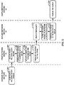
- FIG. 3 is a flow diagram illustrating an example operation for forwarding a packet, in accordance with one or more techniques of this disclosure.
- FIG. 3 is described with respect to first network device 20, service host devices 22, second network device 30, customer edge devices 32, and tunnels 42, 44, 46 of FIG. 1 .
- the techniques of FIG. 3 may be performed by different components of network system 2 or by additional or alternative devices.
- Network system 2 may be configured to deliver one or more services to customer edge devices 32 from service host devices 22.
- a "service" may include video streaming, email messaging, online browsing, or other transfers of data from one party to another.
- a user device which is streaming a video may receive a sequence of packets from a provider edge device. Each packets of the sequence of packets may include a portion of the data required for the user device to stream the video. The sequence of packets including the data for a single video may include a significant number of packets. As such, it may be beneficial for network system 2 to forward the sequence of packets in an efficient manner such that the sequence of packets arrive at a destination (e.g., the user device) in a relatively short amount of time.
- the example operation of FIG. 3 may improve a manner in which network system 2 forward packets over a manner in which network systems forward packets without performing the example operation of FIG. 3 .
- service host devices 22 send a packet including a packet header (302).
- a provider edge device e.g., service host device 22A
- the packet may be associated with a service, and the service may be indicated in the packet header.
- the packet header may include a set of bits which indicate the service associated with the packet.
- the packet header may include a set of bits which indicate a service color associated with the packet header, where the service color is tied to a service or a set of services.
- First network device 20 receives the packet including the packet header (304).
- First network device 20 parses the packet header to determine a service color (306) that is associated with a service that the packet represents.
- first network device 20 parses the packet header which includes a set of bits identifying the service color assigned to the packet. In some examples, the first network device 20 parses the packet header which includes a set of bits identifying the service assigned to the packet and first network device 20 performs an action to look up a service color that is assigned to the packet. For example, first network device may store a list of services, where the list of services identifies one or more service colors associated with each service on the list of services.
- First network device 20 selects a tunnel for forwarding the packet (308).
- first network device 20 selects the tunnel based on a tunnel hierarchy structure stored in a memory of first network device 20.
- the tunnel hierarchy structure may link one or more service colors to one or more tunnel colors such that each service color of the one or more service colors is linked to a set of tunnel colors.
- Each respective set of tunnel colors may represent a hierarchy of tunnel colors such that the set of tunnel colors linked to the service color represents a ranking of tunnel colors.
- Each tunnel of tunnels 42, 44, and 46 may be associated with a tunnel color.
- First network device 20 may include a list of tunnels that indicates one or more tunnel colors associated with each tunnel in the list of tunnels.
- first network device 20 may select the tunnel to forward the packet based on the list of tunnels which indicate tunnel color(s) associated with each tunnel and the tunnel hierarchy structure which links the service color associated with the packet to a set of tunnel colors.
- First network device 20 forwards the packet to second network device 30 (310) via the tunnel selected by first network device 20.
- Second network device 30 receives the packet (312) and parses the packet header of the packet to determine a destination device (314).
- the packet header may include a set of bits which identifies the destination device of the packet, such as a customer edge device of customer edge devices 32.
- Second network device 30 forwards the packet to the destination device (316) and the respective customer edge device of customer edge devices 32 receive the packet (318).
- First network device 20 may be configured to perform one or more operations described as being performed by second network device 30.
- Second network device 30 may be configured to perform one or more operations described as being performed by first network device 20.
- various aspects of the techniques may be performed with packets received from CE devices 32 and forwarded by second network device 30 via tunnels 42, 44, and/or 46 to first network device 20 for delivery to service host devices 22.
- various aspects of the techniques may be performed to deliver packet to and receive packets from CE devices (which are connected to first network device 20) or a combination of CE devices and service host devices.
- one or more of CE devices 32 may be replaced with service host devices that couple to second network devices 30 providing various services accessible by the CE devices coupled to the first network device 20.
- FIG. 4 is a flow diagram illustrating an example operation for selecting a funnel for forwarding a packet, in accordance with one or more techniques of this disclosure.
- FIG. 4 is described with respect to first network device 20, service host devices 22, second network device 30, customer edge devices 32, and tunnels 42, 44, 46 of FIG. 1 .
- the techniques of FIG. 4 may be performed by different components of network system 2 or by additional or alternative devices.
- the example operation illustrated in FIG. 4 may represent an example operation for performing the FIG. 3 step of "SELECT A TUNNEL FOR FORWARDING THE PACKET" (block 308).
- a set of tunnels such as tunnels 42, 44, 46 may carry network traffic between a first network device 20 and a second network device 30.
- Tunnels 42, 44, 46 may include two or more tunnels. In this way, there may be more than one path in which a packet may travel between first network device 20 and second network device 30.
- Tunnels carry packets similar to a way in which pipes carry water. For example, a rate in which a tunnel may carry packets may be limited to a maximum packet transmission rate. As such, if more than one tunnel connects a pair of nodes, it may be beneficial to control which packets are forwarded over the more than one tunnels in order to efficiently transport network traffic between the pair of nodes.
- One way to control packet flow over a set of tunnels connecting the same two nodes is to forward a packet over the set tunnels based on one or more services associated with the packet. Additionally, it may be beneficial to balance a load of packets sent over the set of tunnels.
- first network device 20 may parse the packet header to determine a service color associated with the packet. Subsequently, first network device 20 may identify, based on a tunnel hierarchy structure, a first set of tunnels linked to the service color (402).
- the tunnel hierarchy structure may link a group of tunnels to the service color, the first set of tunnels being a part of the group of tunnels.
- the first set of tunnels is associated with a first tunnel color, where the first tunnel color is linked to the service color in the tunnel hierarchy structure.
- the first set of tunnels represent a primary set of tunnels. The primary set of tunnels may be more preferred for forwarding packets associated with the service color than other tunnels.
- the first set of tunnels may include tunnels 42.
- tunnels 42 may be more preferred for forwarding the packet associated with the service color than tunnels 44 and tunnels 46.
- First network device 20 may determine whether at least one tunnel of the first set of tunnels is activated (404). If first network device 20 determines that at least one tunnel of the first set of tunnels is activated ("YES" branch of block 404), first network device 20 may select a tunnel of the first set of tunnels (406) that is in an online state and forward the packet to second network device 30 over the tunnel (408). In some examples, first network device 20 selects the tunnel in order to load balance network traffic over online tunnels of the first set of tunnels.
- first network device 20 may identify, based on the tunnel hierarchy structure, a second set of tunnels linked to the service color (410).
- the second set of tunnels may be a part of the group of tunnels linked to the service color in the tunnel hierarchy structure.
- the second set of tunnels is associated with a second tunnel color, where the second tunnel color is linked to the service color in the tunnel hierarchy structure.
- the second set of tunnels represents a secondary set of tunnels, or a fallback set of tunnels. The secondary set of tunnels may be less preferred for forwarding packets associated with the service color than the primary set of tunnels.
- the secondary set of tunnels may be more preferred for forwarding packets associated with the service color than a tertiary set of tunnels or other tunnels of tunnels 42, 44, 46 that are not linked to the service color in the tunnel hierarchy structure.
- the second set of tunnels may include tunnels 44.
- tunnels 44 may be more preferred for forwarding the packet associated with the service color than tunnels 46, but less preferred for forwarding the packet than tunnels 42.
- First network device 20 may determine whether at least one tunnel of the second set of tunnels is activated (412).
- first network device 20 may select a tunnel of the second set of tunnels (414) that is in an online state and forward the packet to second network device 30 over the tunnel (416). In some examples, first network device 20 selects the tunnel in order to load balance network traffic over online tunnels of the second set of tunnels.
- first network device 20 may identify, based on the tunnel hierarchy structure, a third set of tunnels linked to the service color (410).
- the third set of tunnels may be a part of the group of tunnels linked to the service color in the tunnel hierarchy structure.
- the third set of tunnels is associated with a third tunnel color, where the third tunnel color is linked to the service color in the tunnel hierarchy structure.
- the third set of tunnels represents a tertiary set of tunnels (e.g., a fallback set of tunnels).
- the tertiary set of tunnels may be less preferred for forwarding packets associated with the service color than the primary set of tunnels and the secondary set of tunnels. However, the tertiary set of tunnels may be more preferred for forwarding packets associated with the service color than tunnels connecting first network device 20 and second network device 30 that are not linked to the service color in the tunnel hierarchy structure.
- the third set of tunnels may include tunnels 46. In such examples, tunnels 46 may be less preferred for forwarding the packet than tunnels 42 and tunnels 44.
- First network device 20 may determine whether at least one tunnel of the third set of tunnels is activated (420).
- first network device 20 may select a tunnel of the third set of tunnels (422) that is in an online state and forward the packet to second network device 30 over the tunnel (424). In some examples, first network device 20 selects the tunnel in order to load balance network traffic over online tunnels of the third set of tunnels. If first network device 20 determines that no tunnels of the third set of tunnels are in an online state ("NO" branch of block 420), first network device 20 may forward the packet to second network device 30 over another tunnel not illustrated in FIG 1 . In some examples, the tunnel hierarchy structure likes more than three or less than three tunnel colors to a service color.
- a network device includes a control unit, a forwarding unit including a forwarding manager including a server configured to store a tunnel hierarchy structure, and a packet processor.
- the packet processor is configured to receive, via an interface card of a set of interface cards, a packet including a packet header.
- the forwarding manager is configured to parse the packet header in order to identify a service corresponding to the packet, wherein the service is associated with a service color, identify, based on the tunnel hierarchy structure, a set of tunnels, wherein each tunnel of the set of tunnels is associated with a tunnel color, and determine whether at least one tunnel of a set of tunnels associated with the tunnel color is in an online state.
- the techniques described herein may be implemented in hardware, software, firmware, or any combination thereof.
- Various features described as modules, units or components may be implemented together in an integrated logic device or separately as discrete but interoperable logic devices or other hardware devices.
- various features of electronic circuitry may be implemented as one or more integrated circuit devices, such as an integrated circuit chip or chipset.
- this disclosure may be directed to an apparatus such as a processor or an integrated circuit device, such as an integrated circuit chip or chipset.
- an apparatus such as a processor or an integrated circuit device, such as an integrated circuit chip or chipset.
- the techniques may be realized at least in part by a computer-readable medium including instructions that, when executed, cause a processor to perform one or more of the methods described above.
- the computer-readable medium may store such instructions for execution by a processor.
- a computer-readable medium may form part of a computer program product, which may include packaging materials.
- a computer-readable medium may include a computer data storage medium such as RAM, read-only memory (ROM), non-volatile random access memory (NVRAM), EEPROM, Flash memory, magnetic or optical data storage media, and the like.
- an article of manufacture may include one or more computer-readable storage media.
- a computer readable medium may also or alternatively include a transient medium such as a carrier wave or transmission signal. Such transient computer readable media may occur within a computer system or between computer systems.
- the computer-readable storage media may include non-transitory media.
- the term "non-transitory” may indicate that the storage medium is not embodied in a carrier wave or a propagated signal.
- a non-transitory storage medium may store data that can, over time, change (e.g., in RAM or cache).
- the code or instructions may be software and/or firmware executed by processing circuitry including one or more processors, such as one or more digital signal processors (DSPs), general purpose microprocessors, application-specific integrated circuits (ASICs), field-programmable gate arrays (FPGAs), or other equivalent integrated or discrete logic circuitry.
- DSPs digital signal processors
- ASICs application-specific integrated circuits
- FPGAs field-programmable gate arrays
- processors may refer to any of the foregoing structure or any other structure suitable for implementation of the techniques described herein.
- functionality described in this disclosure may be provided within software modules or hardware modules.
Applications Claiming Priority (1)
| Application Number | Priority Date | Filing Date | Title |
|---|---|---|---|
| US16/588,387 US11190461B2 (en) | 2019-09-30 | 2019-09-30 | Mapping services to tunnels in order to forward packets using a network device |
Publications (1)
| Publication Number | Publication Date |
|---|---|
| EP3799366A1 true EP3799366A1 (fr) | 2021-03-31 |
Family
ID=68944248
Family Applications (1)
| Application Number | Title | Priority Date | Filing Date |
|---|---|---|---|
| EP19217036.3A Pending EP3799366A1 (fr) | 2019-09-30 | 2019-12-17 | Mappage de services à des tunnels afin de transférer des paquets à l'aide d'un dispositif de réseau |
Country Status (3)
| Country | Link |
|---|---|
| US (1) | US11190461B2 (fr) |
| EP (1) | EP3799366A1 (fr) |
| CN (1) | CN112583689B (fr) |
Families Citing this family (2)
| Publication number | Priority date | Publication date | Assignee | Title |
|---|---|---|---|---|
| CN112788637A (zh) * | 2020-06-29 | 2021-05-11 | 中兴通讯股份有限公司 | 隧道保护方法、边缘路由器和计算机可读介质 |
| CN113726655B (zh) * | 2021-08-30 | 2022-09-20 | 新华三信息安全技术有限公司 | 一种报文引流方法、装置、头端设备及存储介质 |
Citations (3)
| Publication number | Priority date | Publication date | Assignee | Title |
|---|---|---|---|---|
| US20030177221A1 (en) * | 2002-03-18 | 2003-09-18 | Hamid Ould-Brahim | Resource allocation using an auto-discovery mechanism for provider-provisioned layer-2 and layer-3 Virtual Private Networks |
| CN101616051B (zh) * | 2008-06-27 | 2011-09-14 | 华为技术有限公司 | 创建伪线的方法及装置 |
| US20150146536A1 (en) * | 2013-11-25 | 2015-05-28 | Juniper Networks, Inc. | Automatic traffic mapping for multi-protocol label switching networks |
Family Cites Families (4)
| Publication number | Priority date | Publication date | Assignee | Title |
|---|---|---|---|---|
| US20040044789A1 (en) * | 2002-03-11 | 2004-03-04 | Seabridge Ltd. | Dynamic service-aware aggregation of PPP sessions over variable network tunnels |
| US7826367B2 (en) * | 2007-06-28 | 2010-11-02 | Verizon Patent And Licensing Inc. | Systems and methods for protecting a trunk with multiple trunks |
| US8064443B2 (en) | 2009-05-11 | 2011-11-22 | Juniper Networks, Inc. | Scalable routing policy construction using dynamic redefinition of routing preference value |
| US10237165B2 (en) * | 2016-06-13 | 2019-03-19 | Jason Dixon | Data traffic management system and method |
-
2019
- 2019-09-30 US US16/588,387 patent/US11190461B2/en active Active
- 2019-12-17 EP EP19217036.3A patent/EP3799366A1/fr active Pending
- 2019-12-19 CN CN201911319181.3A patent/CN112583689B/zh active Active
Patent Citations (3)
| Publication number | Priority date | Publication date | Assignee | Title |
|---|---|---|---|---|
| US20030177221A1 (en) * | 2002-03-18 | 2003-09-18 | Hamid Ould-Brahim | Resource allocation using an auto-discovery mechanism for provider-provisioned layer-2 and layer-3 Virtual Private Networks |
| CN101616051B (zh) * | 2008-06-27 | 2011-09-14 | 华为技术有限公司 | 创建伪线的方法及装置 |
| US20150146536A1 (en) * | 2013-11-25 | 2015-05-28 | Juniper Networks, Inc. | Automatic traffic mapping for multi-protocol label switching networks |
Non-Patent Citations (1)
| Title |
|---|
| YIMIN SHEN JUNIPER NETWORKS RAVI SINGH INDIVIDUAL CONTRIBUTOR: "BGP Flexible Color-Based Tunnel Selection; draft-shen-idr-flexible-color-tunnel-selection-00.txt", 24 September 2019 (2019-09-24), pages 1 - 12, XP015135296, Retrieved from the Internet <URL:https://tools.ietf.org/html/draft-shen-idr-flexible-color-tunnel-selection-00> [retrieved on 20190924] * |
Also Published As
| Publication number | Publication date |
|---|---|
| US11190461B2 (en) | 2021-11-30 |
| US20210099401A1 (en) | 2021-04-01 |
| CN112583689B (zh) | 2022-08-19 |
| CN112583689A (zh) | 2021-03-30 |
Similar Documents
| Publication | Publication Date | Title |
|---|---|---|
| CN107872392B (zh) | 分配服务功能链数据和服务功能实例数据的方法和装置 | |
| US10693770B2 (en) | Service chaining within computer networks | |
| US10454821B2 (en) | Creating and maintaining segment routed traffic engineering policies via border gateway protocol | |
| EP3879759B1 (fr) | Dépannage de chemin de données optimisé à l'aide d'un moteur de politique de trace | |
| CN109863725B (zh) | 基于最大分段标识符深度的分段路由方法及电子设备 | |
| US9843504B2 (en) | Extending OpenFlow to support packet encapsulation for transport over software-defined networks | |
| US20180013821A1 (en) | Chaining service zones by way of route re-origination | |
| US9094459B2 (en) | Flow based overlay network | |
| JP6967521B2 (ja) | Ospfを利用して最大ノードおよび/またはリンクセグメント識別子深度を明らかにするための技法 | |
| US11159421B2 (en) | Routing table selection in a policy based routing system | |
| EP3821338A1 (fr) | Mécanisme de resynchronisation sans à-coups pendant des mises à niveau de contrôleur sdn entre des versions incompatibles | |
| US20150043348A1 (en) | Traffic Flow Redirection between Border Routers using Routing Encapsulation | |
| EP3834365B1 (fr) | Versionnage d'arbres de distribution multidiffusion pour minimiser les perturbations du trafic des groupes de multidiffusion | |
| WO2017037615A1 (fr) | Procédé et appareil de modification d'états de réacheminement dans un dispositif de réseau d'un réseau défini par logiciel | |
| EP3391588A1 (fr) | Noeuds sdn hybrides divisés horizontalement configurés openflow | |
| EP3183831B1 (fr) | Portail de mise en réseau définie par logiciel | |
| US11425022B1 (en) | Service-based tunnel selection scheme for mapping services to tunnels | |
| US11190461B2 (en) | Mapping services to tunnels in order to forward packets using a network device | |
| US10749702B2 (en) | Multicast service translation in internet protocol television systems | |
| US20120170581A1 (en) | Policy homomorphic network extension | |
| CN113328934A (zh) | 用于将服务映射到隧道的基于服务的传输类别 | |
| US20220311703A1 (en) | Controller watch port for robust software defined networking (sdn) system operation | |
| US11669256B2 (en) | Storage resource controller in a 5G network system |
Legal Events
| Date | Code | Title | Description |
|---|---|---|---|
| PUAI | Public reference made under article 153(3) epc to a published international application that has entered the european phase |
Free format text: ORIGINAL CODE: 0009012 |
|
| STAA | Information on the status of an ep patent application or granted ep patent |
Free format text: STATUS: THE APPLICATION HAS BEEN PUBLISHED |
|
| AK | Designated contracting states |
Kind code of ref document: A1 Designated state(s): AL AT BE BG CH CY CZ DE DK EE ES FI FR GB GR HR HU IE IS IT LI LT LU LV MC MK MT NL NO PL PT RO RS SE SI SK SM TR |
|
| AX | Request for extension of the european patent |
Extension state: BA ME |
|
| STAA | Information on the status of an ep patent application or granted ep patent |
Free format text: STATUS: REQUEST FOR EXAMINATION WAS MADE |
|
| 17P | Request for examination filed |
Effective date: 20210929 |
|
| RBV | Designated contracting states (corrected) |
Designated state(s): AL AT BE BG CH CY CZ DE DK EE ES FI FR GB GR HR HU IE IS IT LI LT LU LV MC MK MT NL NO PL PT RO RS SE SI SK SM TR |
|
| STAA | Information on the status of an ep patent application or granted ep patent |
Free format text: STATUS: EXAMINATION IS IN PROGRESS |
|
| 17Q | First examination report despatched |
Effective date: 20220928 |
|
| GRAP | Despatch of communication of intention to grant a patent |
Free format text: ORIGINAL CODE: EPIDOSNIGR1 |
|
| STAA | Information on the status of an ep patent application or granted ep patent |
Free format text: STATUS: GRANT OF PATENT IS INTENDED |
|
| INTG | Intention to grant announced |
Effective date: 20240209 |
|
| RIC1 | Information provided on ipc code assigned before grant |
Ipc: H04L 45/50 20220101ALI20240129BHEP Ipc: H04L 45/42 20220101ALI20240129BHEP Ipc: H04L 45/302 20220101ALI20240129BHEP Ipc: H04L 45/247 20220101ALI20240129BHEP Ipc: H04L 45/24 20220101ALI20240129BHEP Ipc: H04L 45/00 20220101ALI20240129BHEP Ipc: H04L 12/46 20060101AFI20240129BHEP |