EP3798787A1 - Fahrhebelanordnung - Google Patents
Fahrhebelanordnung Download PDFInfo
- Publication number
- EP3798787A1 EP3798787A1 EP20190905.8A EP20190905A EP3798787A1 EP 3798787 A1 EP3798787 A1 EP 3798787A1 EP 20190905 A EP20190905 A EP 20190905A EP 3798787 A1 EP3798787 A1 EP 3798787A1
- Authority
- EP
- European Patent Office
- Prior art keywords
- driving lever
- arrangement according
- section
- longitudinal direction
- transverse direction
- Prior art date
- Legal status (The legal status is an assumption and is not a legal conclusion. Google has not performed a legal analysis and makes no representation as to the accuracy of the status listed.)
- Granted
Links
Images

Classifications
-
- G—PHYSICS
- G05—CONTROLLING; REGULATING
- G05G—CONTROL DEVICES OR SYSTEMS INSOFAR AS CHARACTERISED BY MECHANICAL FEATURES ONLY
- G05G23/00—Means for ensuring the correct positioning of parts of control mechanisms, e.g. for taking-up play
-
- E—FIXED CONSTRUCTIONS
- E02—HYDRAULIC ENGINEERING; FOUNDATIONS; SOIL SHIFTING
- E02F—DREDGING; SOIL-SHIFTING
- E02F9/00—Component parts of dredgers or soil-shifting machines, not restricted to one of the kinds covered by groups E02F3/00 - E02F7/00
- E02F9/20—Drives; Control devices
- E02F9/2004—Control mechanisms, e.g. control levers
-
- G—PHYSICS
- G05—CONTROLLING; REGULATING
- G05G—CONTROL DEVICES OR SYSTEMS INSOFAR AS CHARACTERISED BY MECHANICAL FEATURES ONLY
- G05G1/00—Controlling members, e.g. knobs or handles; Assemblies or arrangements thereof; Indicating position of controlling members
- G05G1/04—Controlling members for hand actuation by pivoting movement, e.g. levers
-
- G—PHYSICS
- G05—CONTROLLING; REGULATING
- G05G—CONTROL DEVICES OR SYSTEMS INSOFAR AS CHARACTERISED BY MECHANICAL FEATURES ONLY
- G05G9/00—Manually-actuated control mechanisms provided with one single controlling member co-operating with two or more controlled members, e.g. selectively, simultaneously
- G05G9/02—Manually-actuated control mechanisms provided with one single controlling member co-operating with two or more controlled members, e.g. selectively, simultaneously the controlling member being movable in different independent ways, movement in each individual way actuating one controlled member only
- G05G9/04—Manually-actuated control mechanisms provided with one single controlling member co-operating with two or more controlled members, e.g. selectively, simultaneously the controlling member being movable in different independent ways, movement in each individual way actuating one controlled member only in which movement in two or more ways can occur simultaneously
- G05G9/047—Manually-actuated control mechanisms provided with one single controlling member co-operating with two or more controlled members, e.g. selectively, simultaneously the controlling member being movable in different independent ways, movement in each individual way actuating one controlled member only in which movement in two or more ways can occur simultaneously the controlling member being movable by hand about orthogonal axes, e.g. joysticks
- G05G2009/04766—Manually-actuated control mechanisms provided with one single controlling member co-operating with two or more controlled members, e.g. selectively, simultaneously the controlling member being movable in different independent ways, movement in each individual way actuating one controlled member only in which movement in two or more ways can occur simultaneously the controlling member being movable by hand about orthogonal axes, e.g. joysticks providing feel, e.g. indexing means, means to create counterforce
-
- G—PHYSICS
- G05—CONTROLLING; REGULATING
- G05G—CONTROL DEVICES OR SYSTEMS INSOFAR AS CHARACTERISED BY MECHANICAL FEATURES ONLY
- G05G5/00—Means for preventing, limiting or returning the movements of parts of a control mechanism, e.g. locking controlling member
- G05G5/06—Means for preventing, limiting or returning the movements of parts of a control mechanism, e.g. locking controlling member for holding members in one or a limited number of definite positions only
-
- G—PHYSICS
- G05—CONTROLLING; REGULATING
- G05G—CONTROL DEVICES OR SYSTEMS INSOFAR AS CHARACTERISED BY MECHANICAL FEATURES ONLY
- G05G9/00—Manually-actuated control mechanisms provided with one single controlling member co-operating with two or more controlled members, e.g. selectively, simultaneously
- G05G9/02—Manually-actuated control mechanisms provided with one single controlling member co-operating with two or more controlled members, e.g. selectively, simultaneously the controlling member being movable in different independent ways, movement in each individual way actuating one controlled member only
- G05G9/04—Manually-actuated control mechanisms provided with one single controlling member co-operating with two or more controlled members, e.g. selectively, simultaneously the controlling member being movable in different independent ways, movement in each individual way actuating one controlled member only in which movement in two or more ways can occur simultaneously
- G05G9/047—Manually-actuated control mechanisms provided with one single controlling member co-operating with two or more controlled members, e.g. selectively, simultaneously the controlling member being movable in different independent ways, movement in each individual way actuating one controlled member only in which movement in two or more ways can occur simultaneously the controlling member being movable by hand about orthogonal axes, e.g. joysticks
-
- G—PHYSICS
- G05—CONTROLLING; REGULATING
- G05G—CONTROL DEVICES OR SYSTEMS INSOFAR AS CHARACTERISED BY MECHANICAL FEATURES ONLY
- G05G9/00—Manually-actuated control mechanisms provided with one single controlling member co-operating with two or more controlled members, e.g. selectively, simultaneously
- G05G9/10—Manually-actuated control mechanisms provided with one single controlling member co-operating with two or more controlled members, e.g. selectively, simultaneously with preselection and subsequent movement of each controlled member by movement of the controlling member in two different ways, e.g. guided by a shift gate
Definitions
- the present invention relates to a driving lever arrangement for an agricultural vehicle with a gate and a driving lever which engages in the gate and can be moved in the longitudinal direction of the gate in order to control the power of a travel drive.
- the object of the present invention is to create a drive lever arrangement which uses simple means to ensure that the drive lever can be moved smoothly.
- a drive lever arrangement for an agricultural vehicle with a gate and a drive lever that engages the gate can be deflected in a longitudinal direction of the gate from a neutral position into at least one forward travel position and has play in a transverse direction of the gate
- Driving lever is movable at least in the forward position in the transverse direction between an adjustment position in which the driving lever can be moved in the longitudinal direction against a reduced friction torque, and a holding position in which an increased friction torque is impressed on the driving lever.
- a user can reduce the friction that counteracts an adjustment of the driving lever in the longitudinal direction of the gate by deflecting the driving lever in the transverse direction and, in particular, reduce it Avoid jerky start of the adjustment movement.
- An elastic element can be provided in order to act upon the driving lever at least in the forward travel position by an elastic element in the transverse direction from the adjustment position into the holding position.
- the elastic element can be a flexible section of the driving lever or a joint guiding the adjustment movement of the driving lever or a spring acting directly or indirectly on the driving lever.
- An elastic friction body is preferably provided which extends in the longitudinal direction of the link and against which the driving lever is pressed against the friction body in the holding position.
- the formation of the notch can be facilitated by the fact that the friction body evades the pressure of the driving lever by deflecting it from a rest position in a longitudinal direction of the driving lever; such a
- the friction body can in particular be designed as a strip, the dimensions of which in the longitudinal direction of the driving lever are smaller than in the longitudinal and transverse directions of the gate.
- the drive lever In the adjustment position, the drive lever can be completely separated from the friction body; however, this is not necessary in order to be able to move the drive lever evenly.
- the friction body is placed in such a way that the driving lever also forms a notch in the friction body in the adjustment position and that only the depth of the notch is less than in the holding position.
- a handle at an upper end of the drive lever is preferably offset relative to a pivot point at the lower end of the drive lever in the transverse direction of the backdrop, so that a handle on the Handle on the weight exerts a torque on the drive lever, and that the weight acts on the drive lever in the direction of the adjustment position.
- the weight of the user's hand resting on the handle already contributes to the force required to move it into the adjustment position.
- the weight can already be sufficient to overcome the restoring force of the elastic element and to move the drive lever into the adjustment position; This restoring force is preferably so great that the weight is insufficient and, in addition, conscious muscle tension on the part of the user is necessary in order to achieve the Bring the drive lever into the adjustment position; This ensures that if the user only has his hand on the handle, but has no intention of adjusting, the control lever is sufficiently damped.
- the gate can also have a reverse drive section in which the drive lever can be moved in the longitudinal direction between the neutral position and a reverse drive position.
- the forward travel section and the reverse travel section are preferably offset from one another in the transverse direction of the gate and connected by a neutral section extending in the transverse direction.
- a neutral section extending in the transverse direction.
- the adjustment position should be on a side facing away from the neutral section of at least the forward travel section. This forces the user, in order to adjust the driving lever in the longitudinal direction of the link, to press it in the transverse direction in a direction facing away from the reverse travel section and thus reliably prevents an unintentional engagement in the reverse travel section.
- the reverse travel section can also be equipped with a friction body; this is also preferably placed in such a way that the adjustment position is located on a side of the reversing section facing away from the neutral section.
- the drive lever In the neutral position, the drive lever should be in the middle of the neutral section; the same elastic element can be used for this purpose and for acting on the driving lever against the friction body in the forward and possibly reverse travel section.
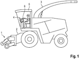
- the in Fig. 1 The forage harvester shown is familiar to the expert in its basic features, so that from a description its usual assemblies such as header 1, intake unit 2, chopper and transfer manifold 3 can be disregarded. Operating elements for controlling the functions of these various units are arranged in a dashboard 4 of a driver's cab 5 and there in particular on a multi-function handle 6.
- the multi-function handle 6 forms the upper end of a driving lever 7, which can be adjusted to control the movement of the forage harvester in relation to the dashboard 4 in the longitudinal direction of a backdrop.
- control lever 7 can be used not only for a forage harvester but also for any other agricultural vehicle such as a tractor or a combine harvester. For this reason, the following description will only refer to a vehicle in general.
- the longitudinal direction is typically parallel to a direction of travel along which the vehicle can move forwards or backwards.
- the drive lever 7 can be deflected forward in the direction of travel, the extent of the deflection specifying a setpoint value for the power of a travel drive of the forage harvester or for its speed in forward travel.
- the drive lever 7 can also be deflected backwards in the direction of travel from the neutral position in order to specify power or speed in reverse travel.
- Fig. 2 shows a perspective view of the driving lever 7 and the link 8 guiding it from FIG Perspective of a driver of the vehicle.
- a rigid plate 9, from which the backdrop 8 is cut out, can be exposed from the driver's perspective or hidden under a panel (not shown here).
- the plate 9 can in particular be part of an armrest adjacent to a driver's seat.
- An upper side of the multi-function handle 6 is provided as a support surface on which the driver's right hand rests during operation.
- the hand can assume a position here in which some of the operating elements of the multifunctional handle 6 are directly on the tips of the driver's fingers and others can be reached by gently pivoting the fingers.
- a shaft 10 of the driving lever 7 extends through the gate 8.
- the gate 8 comprises at least one (in the view of FIG Fig. 2 Forward travel section 11, which is largely hidden by the travel lever 7, in the case shown here also a reverse travel section 12, and a neutral section 13.Forward travel section 11 and reverse travel section 12 extend parallel to one another in a longitudinal direction L of the gate 8, the neutral section 13 connects ends of the sections 11, 12 and extends in the transverse direction T of the link 8.
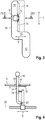
- Fig. 3 shows the cross section of the shaft 10 in the holding position with solid lines and in the adjustment position with dashed lines.
- An elongated, elastically flexible friction body 15 is mounted under the plate 9 on a longitudinal edge 14 of the forward travel section 11.
- the friction body 15 projects from the longitudinal edge 14 into the forward travel section 11.
- the friction body 15 may, for example, be a strip of rubber which is fastened to the plate 9 over a large part of its width, for example by clamping between the plate 9 and a clamping plate screwed to it.
- FIG. 2 and 3 Invisible elastic element acts on the driving lever 7 in the holding position near the longitudinal edge 14.
- the shaft 10 presses in the transverse direction against the friction body 15, so that it is locally deformed under the pressure of the shaft 10 and thereby forms a notch 17, which hugs part of the circumference of the shaft 10 against this.
- the friction body 15 can consist of a rubber-elastic material which is able to yield to a compressive force in that the dimensions of a volume element of the material in the direction of the force decrease and dimensions increase transversely to the direction of force;
- a flat friction body 15 can also yield to the pressure by bending under the pressure and thereby in the longitudinal direction of the shaft 10 is deflected. In Fig. 3 the friction body 15 is bent upwards by the contact with the shaft 10, so that in the area of the notch 17 a narrow side 16 of the friction body 15 is turned upwards.
- the depth of the notch 17 is reduced and the drive lever 7 is easily movable in the longitudinal direction of the link 8.
- the shaft 10 can be separated from the friction body 15;
- the contact between the shaft 10 and the friction body 15 also continues in the adjustment position, but the depth of the notch 17 is reduced, and with it the damping.
- the friction body 15 extends on the same side of the forward travel section 11 on which the neutral section 13 branches off, the same elastic element that urges the shaft 10 against the friction body can also push it into the neutral section 13 when the end of the forward travel section 11 is reached.
- Fig. 4 shows a highly schematic section through the control lever arrangement along the plane IV-IV of FIG Fig. 3 , ie in a plane extending in the transverse direction T and in the longitudinal direction of the shaft 10.
- a movement of the shaft 10 in the transverse direction, along the neutral section 13 or between Adjustment and holding position can be made possible by bearing with play, elastic flexibility of the shaft 10 or in any other way;
- a hinge 21 at a lower end of the shaft 10 guides its movement in the transverse direction T, and that an internal elastic element 19 of the shaft, shown here as a tension spring, pushes the shaft 10 against the friction body 15 applied.
- Fig. 4 shows the shaft 10 in the holding position in which it presses the notch 17 into the friction body 15; In order to reach the adjustment position, the driver pulls the shaft 10 against the restoring force of the elastic element towards the edge 18.
Landscapes
- Physics & Mathematics (AREA)
- General Physics & Mathematics (AREA)
- Engineering & Computer Science (AREA)
- Automation & Control Theory (AREA)
- Mechanical Control Devices (AREA)
Abstract
Description
- Die vorliegende Erfindung betrifft eine Fahrhebelanordnung für ein landwirtschaftliches Fahrzeug mit einer Kulisse und einem Fahrhebel, der in die Kulisse eingreift und in Längsrichtung der Kulisse bewegbar ist, um die Leistung eines Fahrantriebs zu steuern.
- Die Bewegung eines solchen Fahrhebels sollte durch Reibung stark genüg gedämpft sein, um zu verhindern, dass Erschütterungen, denen das Fahrzeug beim Fahren insbesondere auf einer Ackerfläche ausgesetzt ist, zu ungewollten Bewegungen des Fahrhebels führen. Ein Fahrhebel, bei dem solche Bewegung mit Hilfe von aneinandergedrückten Reibflächen unterdrückt werden, ist aus
DE 8206925 U1 bekannt. - Alterung der Reibflächen führt bei solchen Fahrhebelanordnungen häufig dazu, dass zum Inbewegungsetzen des Fahrhebels eine deutlich höhere Kraft aufgewandt wird als zum Aufrechterhalten der Bewegung. Der Fahrhebel neigt dadurch zu ruckartigen Bewegungen, die zu entsprechend ruckartigen Beschleunigungen des Fahrzeugs führen und eine kontinuierliche, feinfühlige Steuerung erschweren.
- Eine Möglichkeit der Abhilfe ist eine aktive Steuerung der Reibung; so ist z.B. aus
DE 102 08 984 B4 eine Fahrhebelanordnung für einen Mähdrescher bekannt, bei dem eine Bewegung des Fahrhebels dämpfende Reibscheiben durch einen elektromagnetischen Antrieb in und außer Eingriff gebracht werden können. Eine solche aktive Steuerung ist jedoch aufwendig und kostspielig; außerdem muss sichergestellt sein, dass eine Störung der aktiven Steuerung die Betätigung des Fahrhebels nicht beeinträchtigen kann. - Aufgabe der vorliegenden Erfindung ist, eine Fahrhebelanordnung zu schaffen, die mit einfachen Mitteln sicherstellt, dass der Fahrhebel ruckfrei bewegt werden kann.
- Die Aufgabe wird gelöst, indem bei einer Fahrhebelanordnung für ein landwirtschaftliches Fahrzeug mit einer Kulisse und einem Fahrhebel, der in die Kulisse eingreift, in einer Längsrichtung der Kulisse aus einer Neutralstellung in wenigstens eine Vorwärtsfahrtstellung auslenkbar ist und in einer Querrichtung der Kulisse Spiel aufweist, der Fahrhebel zumindest in der Vorwärtsfahrtstellung in der Querrichtung zwischen einer Verstellposition, in der der Fahrhebel in der Längsrichtung gegen ein reduziertes Reibmoment bewegbar ist, und einer Halteposition bewegbar ist, in der dem Fahrhebel ein erhöhtes Reibmoment aufgeprägt ist.
- So kann ein Benutzer die Reibung, die einer Verstellung des Fahrhebels in der Längsrichtung der Kulisse entgegenwirkt, durch Auslenken des Fahrhebels in der Querrichtung reduzieren und insbesondere ein ruckartiges Einsetzen der Verstellbewegung vermeiden.
- Ein elastisches Element kann vorgesehen sein, um den Fahrhebel zumindest in der Vorwärtsfahrtstellung durch ein elastisches Element in der Querrichtung aus der Verstellposition in die Halteposition zu beaufschlagen.
- Das elastische Element kann ein biegsamer Abschnitt des Fahrhebels oder eines die Verstellbewegung des Fahrhebels führenden Gelenks oder eine direkt oder indirekt auf den Fahrhebel einwirkende Feder sein.
- Vorzugsweise ist ein elastischer Reibkörper vorgesehen, der sich in der Längsrichtung der Kulisse erstreckt und an den der Fahrhebel in der Halteposition an den Reibkörper angedrückt ist.
- Indem der Reibkörper unter dem Druck des Fahrhebels elastisch verformt wird und eine Kerbe bildet, in die der Fahrhebel eingreift, kann eine große Kontaktfläche zwischen dem Reibkörper und dem Fahrhebel geschaffen werden, der den Fahrhebel in Ruhe sicher fixiert, gleichzeitig genügt aber eine geringe Kraft in der Querrichtung, um den Fahrhebel so auszulenken, dass die Reibung erheblich abnimmt und eine gleichmäßige, ruckfreie Bewegung des Fahrhebels möglich wird.
- Die Bildung der Kerbe kann dadurch erleichtert werden, dass der Reibkörper dem Druck des Fahrhebels durch Auslenkung aus einer Ruhestellung in einer Längsrichtung des Fahrhebels ausweicht; ein solcher Reibkörper kann insbesondere als Streifen ausgebildet sein, dessen Abmessung in der Längsrichtung des Fahrhebels kleiner ist als in Längs- und Querrichtung der Kulisse.
- In der Verstellposition kann der Fahrhebel vollständig vom Reibkörper getrennt sein; dies ist jedoch nicht notwendig, um den Fahrhebel gleichmäßig bewegen zu können. Um auch in der Verstellposition eine Dämpfung des Fahrhebels durch den Reibkörper zu erreichen, ist einer Ausgestaltung zufolge der Reibkörper so platziert, dass der Fahrhebel in der Verstellposition ebenfalls eine Kerbe im Reibkörper formt und dass lediglich die Tiefe der Kerbe geringer ist als in der Halteposition.
- Um die Kraft zu minimieren, die der Benutzer zum Verlagern des Fahrhebels in die Verstellposition aufwenden muss, ist vorzugsweise ein Griff an einem oberen Ende des Fahrhebels relativ zu einem Angelpunkt am unteren Ende des Fahrhebels in der Querrichtung der Kulisse versetzt, so dass ein auf dem Griff lastendes Gewicht ein Drehmoment auf den Fahrhebel ausübt, und dass das Gewicht den Fahrhebel in Richtung der Verstellposition beaufschlagt. So trägt bereits das Gewicht der auf dem Griff ruhenden Hand des Benutzers zu der Kraft bei, die zum Verlagern in die Verstellposition benötigt wird. Das Gewicht kann bereits ausreichend sein, um die Rückstellkraft des elastischen Elements zu überwinden und den Fahrhebel in die Verstellposition zu verlagern; vorzugsweise ist diese Rückstellkraft so groß, dass das Gewicht nicht ausreicht und zusätzlich eine bewusste Muskelanspannung des Benutzers nötig ist, um den Fahrhebel in die Verstellposition zu bringen; so ist sichergestellt, dass wenn der Benutzer lediglich seine Hand auf dem Griff liegen hat, aber keine Verstellabsicht hat, der Fahrhebel ausreichend gedämpft ist.
- Die Kulisse kann außer einen Vorwärtsfahrabschnitt, in dem der Fahrhebel in der Längsrichtung zwischen der Neutralstellung und der Vorwärtsfahrstellung bewegbar ist, auch einen Rückwärtsfahrabschnitt aufweisen, in dem der Fahrhebel in der Längsrichtung zwischen der Neutralstellung und einer Rückwärtsfahrstellung bewegbar ist.
- Um einen versehentlichen Übergang des Fahrhebels zwischen Vorwärts- und Rückwärtsfahrabschnitt zu vermeiden, sind vorzugsweise Vorwärtsfahrabschnitt und Rückwärtsfahrabschnitt in Querrichtung der Kulisse gegeneinander versetzt und durch einen sich in der Querrichtung erstreckenden Neutralabschnitt verbunden. So muss ein Benutzer, um den Fahrhebel von einem Fahrabschnitt in den anderen zu überführen, den Fahrhebel auch in der Querrichtung verstellen.
- Die Verstellposition sollte sich an einer vom Neutralabschnitt abgewandten Seite wenigstens des Vorwärtsfahrabschnitts befinden. Dies zwingt den Benutzer, zum Verstellen des Fahrhebels in der Längsrichtung der Kulisse diesen in der Querrichtung in eine vom Rückwärtsfahrabschnitt abgewandte Richtung zu drücken und verhindert somit sicher ein ungewolltes Einrücken in den Rückwärtsfahrabschnitt.
- Der Rückwärtsfahrabschnitt kann ebenfalls mit einem Reibkörper ausgestattet sein; auch dieser ist vorzugsweise so platziert, dass die Verstellposition sich an einer vom Neutralabschnitt abgewandten Seite des Rückwärtsfahrabschnitts befindet.
- In der Neutralstellung sollte der Fahrhebel in die Mitte des Neutralabschnitts beaufschlagt sein; hierfür und für die Beaufschlagung des Fahrhebels gegen den Reibkörper im Vorwärts- und ggf. Rückwärtsfahrabschnitt kann dasselbe elastische Element verwendet werden.
- Weitere Merkmale und Vorteile der Erfindung ergeben sich aus der nachfolgenden Beschreibung von Ausführungsbeispielen unter Bezugnahme auf die beigefügten Figuren. Es zeigen:
- Fig.1:
- eine schematische Ansicht eines Feldhäckslers als Beispiel eines landwirtschaftlichen Fahrzeugs, für das die Fahrhebelanordnung vorgesehen ist;
- Fig. 2
- eine Ansicht der Fahrhebelanordnung aus der Perspektive eines Benutzers;
- Fig. 3
- eine Draufsicht auf eine Kulisse der Fahrhebelanordnung; und
- Fig. 4
- einen schematischen Schnitt durch eine Fahrhebelanordnung.
- Der in
Fig. 1 gezeigte Feldhäcksler ist dem Fachmann in seinen Grundzügen vertraut, so dass von einer Beschreibung seiner üblichen Baugruppen wie Erntevorsatz 1, Einzugsaggregat 2, Häckselwerk und Überladekrümmer 3 abgesehen werden kann. Bedienelemente zum Steuern der Funktionen dieser diversen Aggregate sind in einem Armaturenbrett 4 einer Fahrerkabine 5 und dort insbesondere an einem Multifunktionsgriff 6 angeordnet. Der Multifunktionsgriff 6 bildet das obere Ende eines Fahrhebels 7, der zum Steuern der Fortbewegung des Feldhäckslers in Bezug auf das Armaturenbrett 4 in Längsrichtung einer Kulisse verstellbar ist. - Natürlich ist der Fahrhebel 7 nicht nur für einen Feldhäcksler sondern auch für beliebige andere landwirtschaftliche Fahrzeuge wie etwa einen Schlepper oder einen Mähdrescher brauchbar. Deswegen ist in der weiteren Beschreibung nur noch allgemein von einem Fahrzeug die Rede.
- Die Längsrichtung ist typischerweise parallel zu einer Fahrtrichtung, entlang derer sich das Fahrzeug vorwärts oder rückwärts bewegen kann. Ausgehend von einer Neutralstellung ist der Fahrhebel 7 in der Fahrtrichtung nach vorn auslenkbar, wobei das Ausmaß der Auslenkung einen Sollwert für die Leistung eines Fahrantriebs des Feldhäckslers oder für dessen Geschwindigkeit in Vorwärtsfahrt vorgibt. Der Fahrhebel 7 kann ferner aus der Neutralstellung in der Fahrtrichtung nach hinten auslenkbar sein, um Leistung oder Geschwindigkeit in Rückwärtsfahrt vorzugeben.
-
Fig. 2 zeigt eine perspektivische Ansicht des Fahrhebels 7 und der ihn führenden Kulisse 8 aus der Perspektive eines Fahrers des Fahrzeugs. Eine starre Platte 9, aus der die Kulisse 8 ausgeschnitten ist, kann aus der Perspektive des Fahrers freiliegen oder unter einer hier nicht dargestellten Verkleidung verborgen sein. Die Platte 9 kann insbesondere Teil einer zu einem Fahrersitz benachbarten Armstütze sein. - Eine Oberseite des Multifunktionsgriffs 6 ist als Auflagefläche vorgesehen, auf der im Betrieb des die rechte Hand des Fahrers ruht. Die Hand kann hier eine Stellung einnehmen, in der einige der Bedienelemente des Multifunktionsgriffs 6 unmittelbar an den Spitzen der Finger des Fahrers liegen und andere durch ein leichtes Schwenken der Finger erreichbar sind.
- Ein Schaft 10 des Fahrhebels 7 erstreckt sich durch die Kulisse 8. Die Kulisse 8 umfasst wenigstens einen (in der Ansicht der
Fig. 2 großenteils durch den Fahrhebel 7 verborgenen) Vorwärtsfahrabschnitt 11, im hier gezeigten Fall auch einen Rückwärtsfahrabschnitt 12, und einen Neutralabschnitt 13. Vorwärtsfahrabschnitt 11 und Rückwärtsfahrabschnitt 12 erstrecken sich parallel zueinander in einer Längsrichtung L der Kulisse 8, der Neutralabschnitt 13 verbindet Enden der Abschnitte 11, 12 und erstreckt sich in Querrichtung T der Kulisse 8. - Wie insbesondere in der Draufsicht auf die Kulisse 8 in
Fig. 3 zu erkennen, ist der Durchmesser des Schafts 10 kleiner als die Breite der Abschnitte 11, 12 in der Querrichtung T, so dass der Fahrhebel 7, wenn er sich in einem der Abschnitte 11, 12 befindet, in geringem Umfang auch in der Querrichtung zwischen einer Halteposition und einer Verstellposition beweglich ist.Fig. 3 zeigt den Querschnitt des Schafts 10 in der Halteposition mit durchgezogenen und in der Verstellposition mit gestrichelten Linien. - An einer Längskante 14 des Vorwärtsfahrabschnitts 11 ist unter der Plate 9 ein langgestreckter, elastisch nachgiebiger Reibkörper 15 montiert. Der Reibkörper 15 springt von der Längskante 14 aus in den Vorwärtsfahrabschnitt 11 vor. Der Reibkörper 15 kann z.B. ein Streifen aus Gummi sein, der auf einem Großteil seiner Breite an der Platte 9 befestigt ist, z.B. durch Klemmen zwischen der Platte 9 und einer daran angeschraubten Klemmplatte.
- Ein in
Fig. 2 und3 nicht sichtbares elastisches Element beaufschlagt den Fahrhebel 7 in die Halteposition nahe der Längskante 14. In dieser Halteposition drückt der Schaft 10 in der Querrichtung gegen den Reibkörper 15, so dass dieser sich unter dem Druck des Schafts 10 lokal verformt und dabei eine Kerbe 17 bildet, die sich auf einem Teil des Umfangs des Schafts 10 an diesen anschmiegt. - Der Reibkörper 15 kann aus einem gummielastischen Material bestehen, das in der Lage ist, einer Drucckraft nachzugeben, indem die Abmessung eines Volumenelements des Materials in Richtung der Kraft kleiner wird und Abmessungen quer zur Kraftrichtung zunehmen; ein flacher Reibkörper 15 kann dem Druck auch nachgeben, indem er sich unter dem Druck verbiegt und dadurch in Längsrichtung des Schafts 10 ausgelenkt wird. In
Fig. 3 ist der Reibkörper 15 durch den Kontakt mit dem Schaft 10 nach oben gebogen, so dass im Bereich der Kerbe 17 eine Schmalseite 16 des Reibkörpers 15 nach oben gekehrt ist. Im einen wie im anderen Fall ist eine Bewegung des Fahrhebels 7 in Längsrichtung der Kulisse 8 einerseits durch großflächigen Kontakt mit dem Reibkörper 15, andererseits dadurch, dass die Bewegung eine weitere Verformung des Reibkörpers 15 erfordert, stark bedämpft. So kann der Fahrer bei Bedarf den Fahrhebel 7 loslassen, ohne dass dieser die eingestellte Position verlässt. - Indem der Fahrer den Fahrhebel 7 mit der Hand zur vom Reibkörper 15 abgewandten Längskante 18 des Vorwärtsfahrabschnitts 11 hin in die Verstellposition auslenkt, wird die Tiefe der Kerbe 17 vermindert, und der Fahrhebel 7 wird in Längsrichtung der Kulisse 8 leicht beweglich. In der Verstellposition kann der Schaft 10 vom Reibkörper 15 getrennt sein; vorzugsweise besteht der Kontakt zwischen Schaft 10 und Reibkörper 15 auch in der Verstellposition fort, doch die Tiefe der Kerbe 17 ist vermindert, und mit ihr auch die Dämpfung.
- Da der Reibkörper 15 sich an derselben Seite des Vorwärtsfahrabschnitts 11 erstreckt, an dem auch der Neutralabschnitt 13 abzweigt, kann dasselbe elastische Element, das den Schaft 10 gegen den Reibkörper beaufschlagt, ihn bei Erreichen des Endes des Vorwärtsfahrabschnitts 11 auch in den Neutralabschnitt 13 hineindrücken.
- Im Rückwärtsfahrabschnitt 12 ist kein Reibkörper vorgesehen; da bei Rückwärtsfahrt der Fahrer die Hand am Fahrhebel lassen soll, ist es hier nicht notwendig, den Fahrhebel so stark zu bedämpfen, dass dieser eine einmal eingestellte Fahrposition auch dann beibehält, wenn er losgelassen wird.
-
Fig. 4 zeigt einen stark schematisierten Schnitt durch die Fahrhebelanordnung entlang der Ebene IV-IV derFig. 3 , d.h. in einer sich in Querrichtung T und in Längsrichtung des Schafts 10 erstreckenden Ebene. Eine Verstellung des Fahrhebels 7 in der Längsrichtung L, entlang de Vorwärtsfahrabschnitts 11 oder des Rückwärtsfahrabschnitts 12, erfolgt durch Schwenken des Fahrhebels 7 um eine in der Querrichtung T orientierte Achse 20. Eine Bewegung des Schafts 10 in der Querrichtung, entlang des Neutralabschnitts 13 oder zwischen Verstell- und Halteposition kann durch spielhaltige Lagerung, elastische Biegsamkeit des Schafts 10 oder auf beliebige andere Weise ermöglicht sein; um das Prinzip zu verdeutlichen, ist hier angenommen, dass ein Scharnier 21 an einem unteren Ende des Schafts 10 dessen Bewegung in der Querrichtung T führt, und dass ein internes elastisches Element 19 des Schafts, hier dargestellt als Zugfeder, den Schaft 10 gegen den Reibkörper 15 beaufschlagt.Fig. 4 zeigt den Schaft 10 in der Halteposition, in der er die Kerbe 17 in den Reibkörper 15 drückt; um die Verstellposition zu erreichen, zieht der Fahrer den Schaft 10 gegen die Rückstellkraft des elastischen Elements zur Kante 18 hin. - Der in
Fig. 4 sichtbare Versatz in Querrichtung T zwischen dem Griff 6 und dem von dem Scharnier 21 definierten Angelpunkt am unteren Ende des Schafts 10 hat zur Folge, dass ein auf dem Griff 6 ruhendes Gewicht ein Drehmoment auf den Fahrhebel 7 in Richtung der Verstellposition ausübt. Daher muss der Fahrer, wenn er seine Hand auf dem Griff 6 abstützt, allenfalls nur noch eine geringe zusätzliche Kraft aufbringen, um den Fahrhebel 7 in die Verstellposition auszulenken. -
- 1
- Erntevorsatz
- 2
- Einzugsaggregat
- 3
- Überladekrümmer
- 4
- Armaturenbrett
- 5
- Fahrerkabine
- 6
- Multifunktionsgriff
- 7
- Fahrhebel
- 8
- Kulisse
- 9
- Platte
- 10
- Schaft
- 11
- Vorwärtsfahrabschnitt
- 12
- Rückwärtsfahrabschnitt
- 13
- Neutralabschnitt
- 14
- Längskante
- 15
- Reibkörper
- 16
- Schmalseite
- 17
- Kerbe
- 18
- Längskante
- 19
- elastisches Element
- 20
- Achse
- 21
- Scharnier
Claims (11)
- Fahrhebelanordnung für ein landwirtschaftliches Fahrzeug mit einer Kulisse (8) und einem Fahrhebel (7), der in die Kulisse (8) eingreift, in einer Längsrichtung (L) der Kulisse (8) aus einer Neutralstellung in wenigstens eine Vorwärtsfahrtstellung auslenkbar ist und in einer Querrichtung (T) der Kulisse (8) Spiel aufweist, dadurch gekennzeichnet, dass der Fahrhebel (7) zumindest in der Vorwärtsfahrtstellung in der Querrichtung (T) zwischen einer Verstellposition, in der der Fahrhebel in der Längsrichtung (L) gegen ein reduziertes Reibmoment bewegbar ist, und einer Halteposition bewegbar ist, in der dem Fahrhebel ein erhöhtes Reibmoment aufgeprägt ist.
- Fahrhebelanordnung nach Anspruch 1, dadurch gekennzeichnet, dass der Fahrhebel (7) in der Querrichtung (T) durch ein elastisches Element (19) in die Halteposition beaufschlagt ist.
- Fahrhebelanordnung nach Anspruch 1 oder 2, dadurch gekennzeichnet, dass ein elastischer Reibkörper (15) sich in der Längsrichtung (L) der Kulisse (8) erstreckt und dass der Fahrhebel (7) in der Halteposition an den Reibkörper (15) angedrückt ist.
- Fahrhebelanordnung nach Anspruch 3, dadurch gekennzeichnet, dass wenigstens in der Halteposition der Reibkörper (15) durch den Fahrhebel (7) elastisch verformt ist, um eine den Fahrhebel (7) aufnehmende Kerbe (17) zu bilden.
- Fahrhebelanordnung nach Anspruch 4, dadurch gekennzeichnet, dass der Reibkörper (15) in Höhe der Kerbe (17) aus einer Ruhestellung in einer Längsrichtung des Fahrhebels (7) ausgelenkt ist.
- Fahrhebelanordnung nach Anspruch 4 oder 5, dadurch gekennzeichnet, dass der Fahrhebel (7) in der Verstellposition ebenfalls eine Kerbe im Reibkörper (15) formt und dass die Tiefe der Kerbe geringer ist als in der Halteposition.
- Fahrhebelanordnung nach einem der vorhergehenden Ansprüche, dadurch gekennzeichnet, dass ein Griff (6) an einem oberen Ende des Fahrhebels (7) relativ zu einem Angelpunkt am unteren Ende des Fahrhebels (7) in der Querrichtung (T) der Kulisse (8) versetzt ist, so dass ein auf dem Griff (6) lastendes Gewicht ein Drehmoment auf den Fahrhebel (7) ausübt, und dass das Gewicht den Fahrhebel (7) in Richtung der Verstellposition beaufschlagt.
- Fahrhebelanordnung nach einem der vorhergehenden Ansprüche, dadurch gekennzeichnet, dass die Kulisse (8) einen Vorwärtsfahrabschnitt (11), in dem der Fahrhebel (7) in der Längsrichtung (L) zwischen der Neutralstellung und der Vorwärtsfahrstellung bewegbar ist, und einen Rückwärtsfahrabschnitt (12) aufweist, in dem der Fahrhebel (7) in der Längsrichtung (L) zwischen der Neutralstellung und einer Rückwärtsfahrstellung bewegbar ist.
- Fahrhebelanordnung nach Anspruch 8, dadurch gekennzeichnet, dass der Vorwärtsfahrabschnitt (11) und der Rückwärtsfahrabschnitt (12) in Querrichtung (T) der Kulisse (7) gegeneinander versetzt und durch einen sich in der Querrichtung (T) erstreckenden Neutralabschnitt (13) verbunden sind.
- Fahrhebelanordnung nach Anspruch 9, dadurch gekennzeichnet, dass die Verstellposition sich an einer vom Neutralabschnitt abgewandten Seite wenigstens des Vorwärtsfahrabschnitts (11), vorzugsweise auch des Rückwärtsfahrabschnitts (12), befindet.
- Fahrhebelanordnung nach Anspruch 9 oder 10, dadurch gekennzeichnet, dass der Fahrhebel (7) in der Neutralstellung in die Mitte des Neutralabschnitts (13) beaufschlagt ist.
Applications Claiming Priority (1)
| Application Number | Priority Date | Filing Date | Title |
|---|---|---|---|
| DE102019126120.1A DE102019126120A1 (de) | 2019-09-27 | 2019-09-27 | Fahrhebelanordnung |
Publications (2)
| Publication Number | Publication Date |
|---|---|
| EP3798787A1 true EP3798787A1 (de) | 2021-03-31 |
| EP3798787B1 EP3798787B1 (de) | 2024-11-27 |
Family
ID=72086753
Family Applications (1)
| Application Number | Title | Priority Date | Filing Date |
|---|---|---|---|
| EP20190905.8A Active EP3798787B1 (de) | 2019-09-27 | 2020-08-13 | Fahrhebelanordnung |
Country Status (2)
| Country | Link |
|---|---|
| EP (1) | EP3798787B1 (de) |
| DE (1) | DE102019126120A1 (de) |
Citations (8)
| Publication number | Priority date | Publication date | Assignee | Title |
|---|---|---|---|---|
| DE8206925U1 (de) | 1981-04-14 | 1982-07-15 | Steyr-Daimler-Puch AG, 1010 Wien | Betaetigungsvorrichtung fuer das stellglied eines motors, eines stufenlosen getriebes od. dgl. |
| US4438660A (en) * | 1981-10-02 | 1984-03-27 | Deere & Company | Dual mode control lever assembly |
| US20060201732A1 (en) * | 2005-03-08 | 2006-09-14 | Dunn James T | Tractor with reversible operator position for operation and transport |
| US20070068323A1 (en) * | 2003-10-11 | 2007-03-29 | Junge Dieter | Selector lever and method for producing a selector lever |
| DE102007005253A1 (de) * | 2007-02-02 | 2008-08-07 | Deere & Company, Moline | Bedienvorrichtung für ein Fahrzeug |
| US7544905B2 (en) * | 2005-12-22 | 2009-06-09 | Penny & Giles Controls Limited | Joystick controller with put-and-stay capability |
| US20120125136A1 (en) * | 2009-02-13 | 2012-05-24 | Zf Friedrichshafen Ag | Arrangement for creating a shifting force or selection force in a manual transmission |
| DE10208984B4 (de) | 2002-02-28 | 2013-07-25 | Deere & Company | Eingabeeinrichtung |
-
2019
- 2019-09-27 DE DE102019126120.1A patent/DE102019126120A1/de not_active Withdrawn
-
2020
- 2020-08-13 EP EP20190905.8A patent/EP3798787B1/de active Active
Patent Citations (8)
| Publication number | Priority date | Publication date | Assignee | Title |
|---|---|---|---|---|
| DE8206925U1 (de) | 1981-04-14 | 1982-07-15 | Steyr-Daimler-Puch AG, 1010 Wien | Betaetigungsvorrichtung fuer das stellglied eines motors, eines stufenlosen getriebes od. dgl. |
| US4438660A (en) * | 1981-10-02 | 1984-03-27 | Deere & Company | Dual mode control lever assembly |
| DE10208984B4 (de) | 2002-02-28 | 2013-07-25 | Deere & Company | Eingabeeinrichtung |
| US20070068323A1 (en) * | 2003-10-11 | 2007-03-29 | Junge Dieter | Selector lever and method for producing a selector lever |
| US20060201732A1 (en) * | 2005-03-08 | 2006-09-14 | Dunn James T | Tractor with reversible operator position for operation and transport |
| US7544905B2 (en) * | 2005-12-22 | 2009-06-09 | Penny & Giles Controls Limited | Joystick controller with put-and-stay capability |
| DE102007005253A1 (de) * | 2007-02-02 | 2008-08-07 | Deere & Company, Moline | Bedienvorrichtung für ein Fahrzeug |
| US20120125136A1 (en) * | 2009-02-13 | 2012-05-24 | Zf Friedrichshafen Ag | Arrangement for creating a shifting force or selection force in a manual transmission |
Also Published As
| Publication number | Publication date |
|---|---|
| DE102019126120A1 (de) | 2021-04-01 |
| EP3798787B1 (de) | 2024-11-27 |
Similar Documents
| Publication | Publication Date | Title |
|---|---|---|
| EP2917076B1 (de) | Scheibenwischvorrichtung für ein fahrzeug | |
| EP2374657B1 (de) | Armlehne und Bedienarbeitsplatz mit einer solchen Armlehne | |
| DE2160278C2 (de) | Selbstnachstellende Betätigungsvorrichtung für eine Kraftfahrzeugkupplung | |
| EP1268273B1 (de) | Piezoelektrische betätigungseinrichtung zur klappensteuerung am rotorblatt eines hubschraubers | |
| EP1957341B1 (de) | Verstellbare lenksäule für ein kraftfahrzeug | |
| EP2271514A1 (de) | Betätigungseinheit eines kraftfahrzeugsitzes | |
| DE202006021160U1 (de) | Verstellbare Lenksäule für ein Kraftfahrzeug | |
| EP1180449B1 (de) | Gefederter Fahrzeugsitz | |
| EP1124123B1 (de) | Vorrichtung zum Befestigen von Ausgleichsgewichten zum Unwuchtausgleich | |
| DE3437476C2 (de) | Führung für eine Tragstange einer höhenverschiebbaren Kopfstütze | |
| EP1411285B1 (de) | Piezoelektrisches Ventil | |
| EP1877886B1 (de) | Anordnung zum betätigen einer kupplung eines fahrzeuges | |
| DE69818400T2 (de) | Hilfeeinrichtung zur Betätigung eines Hebels | |
| EP3798787B1 (de) | Fahrhebelanordnung | |
| DE102012025389B4 (de) | Verstellbare Vorrichtung, insbesondere Kopfstütze und/oder Nackenstütze, für Kraftfahrzeugsitze | |
| DE10258938A1 (de) | Betätigungseinrichtung für eine Kraftfahrzeugkupplung | |
| DE102004051694A1 (de) | Verriegelungsmechanismus für Kraftfahrzeugsitzschienen | |
| EP0230516A2 (de) | Betätigungsvorrichtung für das Leistungssteuerorgan einer Brennkraftmaschine | |
| DE69009621T2 (de) | Kraftfahrzeugscheibenwischer mit veränderbarem Druck. | |
| DE1235153B (de) | Einrichtung zur Unterstuetzung der Pedalkraft, vorzugsweise fuer die Betaetigung einer ausrueck-baren Fahrzeugkupplung, insbesondere Hauptkupplung fuer Kraftfahrzeuge | |
| EP1048513B2 (de) | Handhebelvorrichtung für eine Betätigungseinrichtung an einem Fahrzeugsitz | |
| EP0935489A1 (de) | Vorrichtung zur veränderung der seitwärtsneigung eines skischuhs auf einem ski | |
| EP1048512B1 (de) | Handhebelvorrichtung für eine Betätigungseinrichtung an einem Fahrzeugsitz | |
| EP4001028B1 (de) | Handbremsbetätigungsvorrichtung | |
| DE4315844C2 (de) | Bogengreifer an einem papierführenden Zylinder einer Bogendruckmaschine |
Legal Events
| Date | Code | Title | Description |
|---|---|---|---|
| PUAI | Public reference made under article 153(3) epc to a published international application that has entered the european phase |
Free format text: ORIGINAL CODE: 0009012 |
|
| STAA | Information on the status of an ep patent application or granted ep patent |
Free format text: STATUS: THE APPLICATION HAS BEEN PUBLISHED |
|
| AK | Designated contracting states |
Kind code of ref document: A1 Designated state(s): AL AT BE BG CH CY CZ DE DK EE ES FI FR GB GR HR HU IE IS IT LI LT LU LV MC MK MT NL NO PL PT RO RS SE SI SK SM TR |
|
| AX | Request for extension of the european patent |
Extension state: BA ME |
|
| STAA | Information on the status of an ep patent application or granted ep patent |
Free format text: STATUS: REQUEST FOR EXAMINATION WAS MADE |
|
| 17P | Request for examination filed |
Effective date: 20210930 |
|
| RBV | Designated contracting states (corrected) |
Designated state(s): AL AT BE BG CH CY CZ DE DK EE ES FI FR GB GR HR HU IE IS IT LI LT LU LV MC MK MT NL NO PL PT RO RS SE SI SK SM TR |
|
| P01 | Opt-out of the competence of the unified patent court (upc) registered |
Effective date: 20230516 |
|
| GRAP | Despatch of communication of intention to grant a patent |
Free format text: ORIGINAL CODE: EPIDOSNIGR1 |
|
| STAA | Information on the status of an ep patent application or granted ep patent |
Free format text: STATUS: GRANT OF PATENT IS INTENDED |
|
| INTG | Intention to grant announced |
Effective date: 20240702 |
|
| GRAS | Grant fee paid |
Free format text: ORIGINAL CODE: EPIDOSNIGR3 |
|
| GRAA | (expected) grant |
Free format text: ORIGINAL CODE: 0009210 |
|
| STAA | Information on the status of an ep patent application or granted ep patent |
Free format text: STATUS: THE PATENT HAS BEEN GRANTED |
|
| AK | Designated contracting states |
Kind code of ref document: B1 Designated state(s): AL AT BE BG CH CY CZ DE DK EE ES FI FR GB GR HR HU IE IS IT LI LT LU LV MC MK MT NL NO PL PT RO RS SE SI SK SM TR |
|
| REG | Reference to a national code |
Ref country code: GB Ref legal event code: FG4D Free format text: NOT ENGLISH |
|
| REG | Reference to a national code |
Ref country code: CH Ref legal event code: EP |
|
| REG | Reference to a national code |
Ref country code: DE Ref legal event code: R096 Ref document number: 502020009821 Country of ref document: DE |
|
| REG | Reference to a national code |
Ref country code: IE Ref legal event code: FG4D Free format text: LANGUAGE OF EP DOCUMENT: GERMAN |
|
| REG | Reference to a national code |
Ref country code: LT Ref legal event code: MG9D |
|
| REG | Reference to a national code |
Ref country code: NL Ref legal event code: MP Effective date: 20241127 |
|
| PG25 | Lapsed in a contracting state [announced via postgrant information from national office to epo] |
Ref country code: HR Free format text: LAPSE BECAUSE OF FAILURE TO SUBMIT A TRANSLATION OF THE DESCRIPTION OR TO PAY THE FEE WITHIN THE PRESCRIBED TIME-LIMIT Effective date: 20241127 Ref country code: PT Free format text: LAPSE BECAUSE OF FAILURE TO SUBMIT A TRANSLATION OF THE DESCRIPTION OR TO PAY THE FEE WITHIN THE PRESCRIBED TIME-LIMIT Effective date: 20250327 Ref country code: IS Free format text: LAPSE BECAUSE OF FAILURE TO SUBMIT A TRANSLATION OF THE DESCRIPTION OR TO PAY THE FEE WITHIN THE PRESCRIBED TIME-LIMIT Effective date: 20250327 |
|
| PG25 | Lapsed in a contracting state [announced via postgrant information from national office to epo] |
Ref country code: FI Free format text: LAPSE BECAUSE OF FAILURE TO SUBMIT A TRANSLATION OF THE DESCRIPTION OR TO PAY THE FEE WITHIN THE PRESCRIBED TIME-LIMIT Effective date: 20241127 Ref country code: NL Free format text: LAPSE BECAUSE OF FAILURE TO SUBMIT A TRANSLATION OF THE DESCRIPTION OR TO PAY THE FEE WITHIN THE PRESCRIBED TIME-LIMIT Effective date: 20241127 |
|
| PG25 | Lapsed in a contracting state [announced via postgrant information from national office to epo] |
Ref country code: BG Free format text: LAPSE BECAUSE OF FAILURE TO SUBMIT A TRANSLATION OF THE DESCRIPTION OR TO PAY THE FEE WITHIN THE PRESCRIBED TIME-LIMIT Effective date: 20241127 |
|
| PG25 | Lapsed in a contracting state [announced via postgrant information from national office to epo] |
Ref country code: ES Free format text: LAPSE BECAUSE OF FAILURE TO SUBMIT A TRANSLATION OF THE DESCRIPTION OR TO PAY THE FEE WITHIN THE PRESCRIBED TIME-LIMIT Effective date: 20241127 |
|
| PG25 | Lapsed in a contracting state [announced via postgrant information from national office to epo] |
Ref country code: NO Free format text: LAPSE BECAUSE OF FAILURE TO SUBMIT A TRANSLATION OF THE DESCRIPTION OR TO PAY THE FEE WITHIN THE PRESCRIBED TIME-LIMIT Effective date: 20250227 |
|
| PG25 | Lapsed in a contracting state [announced via postgrant information from national office to epo] |
Ref country code: GR Free format text: LAPSE BECAUSE OF FAILURE TO SUBMIT A TRANSLATION OF THE DESCRIPTION OR TO PAY THE FEE WITHIN THE PRESCRIBED TIME-LIMIT Effective date: 20250228 Ref country code: LV Free format text: LAPSE BECAUSE OF FAILURE TO SUBMIT A TRANSLATION OF THE DESCRIPTION OR TO PAY THE FEE WITHIN THE PRESCRIBED TIME-LIMIT Effective date: 20241127 |
|
| PG25 | Lapsed in a contracting state [announced via postgrant information from national office to epo] |
Ref country code: PL Free format text: LAPSE BECAUSE OF FAILURE TO SUBMIT A TRANSLATION OF THE DESCRIPTION OR TO PAY THE FEE WITHIN THE PRESCRIBED TIME-LIMIT Effective date: 20241127 |
|
| PG25 | Lapsed in a contracting state [announced via postgrant information from national office to epo] |
Ref country code: RS Free format text: LAPSE BECAUSE OF FAILURE TO SUBMIT A TRANSLATION OF THE DESCRIPTION OR TO PAY THE FEE WITHIN THE PRESCRIBED TIME-LIMIT Effective date: 20250227 |
|
| PG25 | Lapsed in a contracting state [announced via postgrant information from national office to epo] |
Ref country code: SM Free format text: LAPSE BECAUSE OF FAILURE TO SUBMIT A TRANSLATION OF THE DESCRIPTION OR TO PAY THE FEE WITHIN THE PRESCRIBED TIME-LIMIT Effective date: 20241127 |
|
| PG25 | Lapsed in a contracting state [announced via postgrant information from national office to epo] |
Ref country code: DK Free format text: LAPSE BECAUSE OF FAILURE TO SUBMIT A TRANSLATION OF THE DESCRIPTION OR TO PAY THE FEE WITHIN THE PRESCRIBED TIME-LIMIT Effective date: 20241127 |
|
| PG25 | Lapsed in a contracting state [announced via postgrant information from national office to epo] |
Ref country code: EE Free format text: LAPSE BECAUSE OF FAILURE TO SUBMIT A TRANSLATION OF THE DESCRIPTION OR TO PAY THE FEE WITHIN THE PRESCRIBED TIME-LIMIT Effective date: 20241127 |
|
| PG25 | Lapsed in a contracting state [announced via postgrant information from national office to epo] |
Ref country code: RO Free format text: LAPSE BECAUSE OF FAILURE TO SUBMIT A TRANSLATION OF THE DESCRIPTION OR TO PAY THE FEE WITHIN THE PRESCRIBED TIME-LIMIT Effective date: 20241127 |
|
| PG25 | Lapsed in a contracting state [announced via postgrant information from national office to epo] |
Ref country code: SK Free format text: LAPSE BECAUSE OF FAILURE TO SUBMIT A TRANSLATION OF THE DESCRIPTION OR TO PAY THE FEE WITHIN THE PRESCRIBED TIME-LIMIT Effective date: 20241127 |
|
| PG25 | Lapsed in a contracting state [announced via postgrant information from national office to epo] |
Ref country code: CZ Free format text: LAPSE BECAUSE OF FAILURE TO SUBMIT A TRANSLATION OF THE DESCRIPTION OR TO PAY THE FEE WITHIN THE PRESCRIBED TIME-LIMIT Effective date: 20241127 |
|
| PG25 | Lapsed in a contracting state [announced via postgrant information from national office to epo] |
Ref country code: IT Free format text: LAPSE BECAUSE OF FAILURE TO SUBMIT A TRANSLATION OF THE DESCRIPTION OR TO PAY THE FEE WITHIN THE PRESCRIBED TIME-LIMIT Effective date: 20241127 |
|
| REG | Reference to a national code |
Ref country code: DE Ref legal event code: R097 Ref document number: 502020009821 Country of ref document: DE |
|
| PG25 | Lapsed in a contracting state [announced via postgrant information from national office to epo] |
Ref country code: SE Free format text: LAPSE BECAUSE OF FAILURE TO SUBMIT A TRANSLATION OF THE DESCRIPTION OR TO PAY THE FEE WITHIN THE PRESCRIBED TIME-LIMIT Effective date: 20241127 |
|
| PLBE | No opposition filed within time limit |
Free format text: ORIGINAL CODE: 0009261 |
|
| STAA | Information on the status of an ep patent application or granted ep patent |
Free format text: STATUS: NO OPPOSITION FILED WITHIN TIME LIMIT |
|
| REG | Reference to a national code |
Ref country code: CH Ref legal event code: L10 Free format text: ST27 STATUS EVENT CODE: U-0-0-L10-L00 (AS PROVIDED BY THE NATIONAL OFFICE) Effective date: 20251008 |
|
| PGFP | Annual fee paid to national office [announced via postgrant information from national office to epo] |
Ref country code: DE Payment date: 20250820 Year of fee payment: 6 |
|
| PGFP | Annual fee paid to national office [announced via postgrant information from national office to epo] |
Ref country code: BE Payment date: 20250820 Year of fee payment: 6 |
|
| 26N | No opposition filed |
Effective date: 20250828 |
|
| REG | Reference to a national code |
Ref country code: CH Ref legal event code: H13 Free format text: ST27 STATUS EVENT CODE: U-0-0-H10-H13 (AS PROVIDED BY THE NATIONAL OFFICE) Effective date: 20260324 |
|
| PG25 | Lapsed in a contracting state [announced via postgrant information from national office to epo] |
Ref country code: MC Free format text: LAPSE BECAUSE OF FAILURE TO SUBMIT A TRANSLATION OF THE DESCRIPTION OR TO PAY THE FEE WITHIN THE PRESCRIBED TIME-LIMIT Effective date: 20241127 |
|
| PG25 | Lapsed in a contracting state [announced via postgrant information from national office to epo] |
Ref country code: LU Free format text: LAPSE BECAUSE OF NON-PAYMENT OF DUE FEES Effective date: 20250813 |
|
| PG25 | Lapsed in a contracting state [announced via postgrant information from national office to epo] |
Ref country code: CH Free format text: LAPSE BECAUSE OF NON-PAYMENT OF DUE FEES Effective date: 20250831 |
|
| GBPC | Gb: european patent ceased through non-payment of renewal fee |
Effective date: 20250813 |