EP3798650B1 - Isolationsdiagnose und lokalisierungsverfahren für isolierte rohrartige sammelschiene - Google Patents
Isolationsdiagnose und lokalisierungsverfahren für isolierte rohrartige sammelschiene Download PDFInfo
- Publication number
- EP3798650B1 EP3798650B1 EP20711768.0A EP20711768A EP3798650B1 EP 3798650 B1 EP3798650 B1 EP 3798650B1 EP 20711768 A EP20711768 A EP 20711768A EP 3798650 B1 EP3798650 B1 EP 3798650B1
- Authority
- EP
- European Patent Office
- Prior art keywords
- grounded
- segment
- ground
- insulated bus
- bus pipe
- Prior art date
- Legal status (The legal status is an assumption and is not a legal conclusion. Google has not performed a legal analysis and makes no representation as to the accuracy of the status listed.)
- Active
Links
Images

Classifications
-
- G—PHYSICS
- G01—MEASURING; TESTING
- G01R—MEASURING ELECTRIC VARIABLES; MEASURING MAGNETIC VARIABLES
- G01R31/00—Arrangements for testing electric properties; Arrangements for locating electric faults; Arrangements for electrical testing characterised by what is being tested not provided for elsewhere
- G01R31/08—Locating faults in cables, transmission lines, or networks
- G01R31/081—Locating faults in cables, transmission lines, or networks according to type of conductors
-
- G—PHYSICS
- G01—MEASURING; TESTING
- G01R—MEASURING ELECTRIC VARIABLES; MEASURING MAGNETIC VARIABLES
- G01R31/00—Arrangements for testing electric properties; Arrangements for locating electric faults; Arrangements for electrical testing characterised by what is being tested not provided for elsewhere
- G01R31/12—Testing dielectric strength or breakdown voltage ; Testing or monitoring effectiveness or level of insulation, e.g. of a cable or of an apparatus, for example using partial discharge measurements; Electrostatic testing
- G01R31/1227—Testing dielectric strength or breakdown voltage ; Testing or monitoring effectiveness or level of insulation, e.g. of a cable or of an apparatus, for example using partial discharge measurements; Electrostatic testing of components, parts or materials
- G01R31/1245—Testing dielectric strength or breakdown voltage ; Testing or monitoring effectiveness or level of insulation, e.g. of a cable or of an apparatus, for example using partial discharge measurements; Electrostatic testing of components, parts or materials of line insulators or spacers, e.g. ceramic overhead line cap insulators; of insulators in HV bushings
-
- G—PHYSICS
- G01—MEASURING; TESTING
- G01R—MEASURING ELECTRIC VARIABLES; MEASURING MAGNETIC VARIABLES
- G01R27/00—Arrangements for measuring resistance, reactance, impedance, or electric characteristics derived therefrom
- G01R27/02—Measuring real or complex resistance, reactance, impedance, or other two-pole characteristics derived therefrom, e.g. time constant
- G01R27/26—Measuring inductance or capacitance; Measuring quality factor, e.g. by using the resonance method; Measuring loss factor; Measuring dielectric constants ; Measuring impedance or related variables
- G01R27/2605—Measuring capacitance
-
- G—PHYSICS
- G01—MEASURING; TESTING
- G01R—MEASURING ELECTRIC VARIABLES; MEASURING MAGNETIC VARIABLES
- G01R31/00—Arrangements for testing electric properties; Arrangements for locating electric faults; Arrangements for electrical testing characterised by what is being tested not provided for elsewhere
- G01R31/08—Locating faults in cables, transmission lines, or networks
- G01R31/088—Aspects of digital computing
Definitions
- the present application relates to a technical field of power transmission and distribution, in particular, to an insulation diagnosis and positioning method for an insulated bus pipe.
- the insulated bus pipe is a current-carrying equipment with copper or aluminum metal round tube as a conductor, and has an insulating casing and an outer grounding shield layer.
- the common voltage level is 6 kV-35 kV, and is mostly used as current-carrying equipment to connect a low-voltage side of the transformer and the switch cabinet.
- the unique structural characteristic enables the insulated bus pipe to have outstanding advantages of large current-carrying capacity, good mechanical properties, safety, space-saving, small maintenance and good weather resistance. With the development trend of large-capacity, compaction, high safety and high environmental compatibility requirement for power transmission, the insulated bus pipe has been widely used for being suitable for the above development requirements.
- the present application provides a rapid insulation diagnosis and defect positioning method which requires less devices, has a high performance on common defects and hidden dangers and is easy to be implemented and executed at maintenance sites.
- the present application solves the problem of rapid insulation state diagnosis and defect positioning of the equipment by utilizing a structural characteristic of multi-segment connection and segmented grounding of the insulated bus pipe.
- the insulated bus pipe equipment includes multiple segments which are integrated into a whole, and is grounding in segments, such grounding manner is complex, but provides convenience for insulation status detection and fault positioning of this type of equipment. Therefore, the present disclosure provides an insulation diagnosis and defect positioning method based on the ground current measurement.
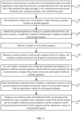
- FIG. 1 is a flowchart of an insulation diagnosis and defect positioning method for an insulated bus pipe provided by an embodiment of the present disclosure. Referring to FIG. 1 , the method provided by the present disclosure includes the steps described below.
- step 110 a first end of an insulated bus pipe is disconnected from other equipment and a second end of the insulated bus pipe is disconnected from other equipment, a connection between a ground electrode and a line ground wiring of the insulated bus pipe is kept, and a test voltage is applied between the ground electrode and a conductor portion of the insulated bus pipe.
- step 120 the test voltage and a test frequency is recorded during the measurement of ground currents of grounded segments.
- step 130 the multiple grounded segments are identified according to a ground shielded short wiring, and a quantity, a length and a number of intermediate couplings included in each grounded segment are recorded.
- step 140 a length of each grounded segment is measured.
- step 150 a ground current of each grounded segment is measured at the test voltage, and a ground current per unit length of each grounded segment is calculated.
- step 160 in a case where a consistent test voltage and test frequency are applied to different grounded segments and the different grounded segments have a same structure, the ground currents per unit length of different grounded segments are compared.
- step 170 manufacturer experience data is checked, the manufacturer experience data includes a capacitance c b per unit length of an insulated bus pipe body, a capacitance c j per unit length of the intermediate coupling or ex-factory test data of the capacitance of each intermediate coupling: capacitances of the intermediate couplings numbered k, k + 1, ..., k + n included in each insulated bus pipe grounded section are respectively C jk , C jk+1 , ...
- the ground current of each insulated bus pipe grounded section is compared with the capacitance current value of each insulated bus pipe grounded section.
- step 180 an insulation status is diagnosed and defect positioning of the insulated bus pipe is implemented according to a comparison result of the ground currents per unit length of different grounded segments and a comparison result between the ground current of each grounded segment and the capacitance current value of each grounded segment.
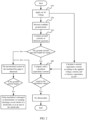
- Insulation diagnosis and defect positioning for the insulated bus pipe are illustrated according to the flowchart described in FIG. 2 , the method provided by the embodiment of the present disclosure includes the steps described below.
- step 210 wirings are connected according to the connection manner shown in FIG. 3 , and a voltage is applied.
- the wirings are connected according to the connection manner shown in FIG. 3 .
- An AC test voltage is applied between a conductor portion of the insulated bus pipe and the ground electrode. If a multi-phrase insulated bus pipe is used, multiple phrases are applied at the same time. The voltage is applied in a frequency series resonance method, or a parallel compensation method or is directly applied.
- an amplitude and frequency of the applied voltage are selected according to the following requirements: a voltage amplitude U t is not lower than 5kV and is not higher than a withstand voltage test level in an equipment status maintenance test; the frequency ranges from 30Hz to 300Hz; a waveform of the test voltage is a sine wave which is approximately symmetrical with respect to positive and negative axes.
- test voltage is adjusted to an appropriate voltage frequency and is gradually boosted to U t . After the voltage is stable, the measurement may be performed and the voltage is kept until the measurement ends.
- step 220 a ground current and test related parameters of each grounded segment are measured.
- Data ( U t , f , l, I ) measured in this step is the analyzing basis for the insulation diagnosis and defect positioning of the insulated bus pipe.
- step 230 the ground current values per unit length of different grounded segments are compared.
- the ground currents ( I / l) per unit length of different grounded segments are compared.
- the ground currents per unit length of different grounded segments are basically equal.
- the insulation status of the insulated bus pipe is abnormal, and a determination method is shown in step 250.
- the same structure includes that the grounded segment has the same quantity of intermediate couplings and the same quantity of insulated bus pipe bodies.
- a measured value of the ground current of the grounded segment is compared with a capacitance current calculation value of this grounded segment.
- manufacturer experience data includes a capacitance c b per unit length of the body, a capacitance c j per unit length of the intermediate coupling, or ex-factory test data of the capacitance of each intermediate coupling: the capacitances of the intermediate couplings numbered k, k + 1... are respectively C jk , C jk+1 , ....
- the measured value of the ground current is compared with the capacitance current value of each grounded segment.
- the measured value of the ground current and the capacitance current value are basically equal for each grounded segment.
- step 250 according to the comparison results of the steps 230 and 240, the insulation status is diagnosed and defects of the insulated bus pipe are positioned.
- ground current values per unit length of different grounded segments are compared. If the ground current values per unit length of the different grounded segments are approximately equal (for example, for each grounded segment, a difference between the ground current per unit length of this grounded segment and the ground current per unit length of each other grounded segment is less than or equal to 10% of the ground current per unit length of this grounded segment), it is considered that the ground current indicator of the of the insulated bus pipe is normal.
- the grounded segment is a defect segment or fault segment.
- the measured value of the ground current of the grounded segment may be compared with the capacitance current calculation value of this grounded segment. If the difference between the measured value of the ground current and the capacitance current calculation value of each grounded segment is very small (for example, the difference between the ground current and the capacitance current value is less than or equal to 3% of the capacitance current value, it is considered that the ground current indicator of the insulated bus pipe is normal.
- the grounded segment is the defect segment or the fault segment.
- the equipment has insulation deterioration, or creeping discharging occurs inside or at an end of the intermediate coupling.
- step 260 the insulation diagnosis and defect positioning end, and test wirings are removed.
Landscapes
- Physics & Mathematics (AREA)
- General Physics & Mathematics (AREA)
- Engineering & Computer Science (AREA)
- Mathematical Physics (AREA)
- Theoretical Computer Science (AREA)
- Chemical & Material Sciences (AREA)
- Ceramic Engineering (AREA)
- Locating Faults (AREA)
- Measurement Of Resistance Or Impedance (AREA)
- Testing Of Short-Circuits, Discontinuities, Leakage, Or Incorrect Line Connections (AREA)
Claims (5)
- Ein Isolationsdiagnose- und Fehlerortungsverfahren für eine isolierte Busleitung, basierend auf einer Erdstrommessung, das Folgendes aufweist:in Schritt 1, Verbinden von Prüfkabeln und Anlegen einer Wechselspannung:
Trennen (110) eines ersten Endes der isolierten Busleitung von anderen Geräten und eines zweiten Endes der isolierten Busleitung von anderen Geräten, Aufrechterhalten der Verbindung zwischen einer Erdungselektrode und einer Leitungserdungsverdrahtung der isolierten Busleitung und Anlegen einer Prüfspannung zwischen der Erdungselektrode und einem Leiterabschnitt der isolierten Busleitung;in Schritt 2, Messen eines Erdstroms und prüfungsbezogener Parameter jedes einer Vielzahl von geerdeten Segmenten der isolierten Busleitung:(1) Aufzeichnen (120) einer Prüfspannung U t und einer Frequenz f zum Zeitpunkt der Messung des Erdstroms jedes der mehreren geerdeten Segmente der isolierten Busleitung;(2) Identifizieren (130) der Vielzahl von geerdeten Segmenten gemäß einer Leitungserdungsverdrahtung und einer abgeschirmten Erdkurzschlussverdrahtung;(3) Messen (140) einer Länge L jedes der Vielzahl von geerdeten Segmenten und Aufzeichnen einer Menge, einer Anzahl und einer Länge von Zwischenkupplungen, die in jedem der Vielzahl von geerdeten Segmenten enthalten sind;(4) Messen (150) des geerdeten Stroms I jedes der Vielzahl von geerdeten Segmenten bei der Prüfspannung U t;in Schritt 3, Vergleichen von Erdströmen pro Längeneinheit von verschiedenen der Vielzahl von geerdeten Segmenten, um ein erstes Vergleichsergebnis zu erhalten: in einem Fall, in dem an die Vielzahl von geerdeten Segmenten eine konsistente Prüfspannung U t und Frequenz f angelegt werden und diese eine gleiche Struktur haben, Vergleichen (160) der Erdströme pro Längeneinheit I/L der verschiedenen der Vielzahl von geerdeten Segmenten;in Schritt 4, Vergleichen des geerdeten Stroms mit einem Kapazitätsstrom-Berechnungswert für jedes der Vielzahl von geerdeten Segmenten bei der geprüften Spannung U t und Frequenz f:Überprüfen (170) von Herstellererfahrungsdaten, wobei die Herstellererfahrungsdaten eine Kapazität cb pro Längeneinheit eines isolierten Busleitungskörpers, eine Kapazität cj pro Längeneinheit der Zwischenkupplung oder werkseitige Testdaten der Kapazität jeder Zwischenkupplung aufweisen: Kapazitäten der in jedem geerdeten Segment enthaltenen Zwischenkupplungen mit der Nummer k, k + 1,..., k + n sind jeweils Cjk,C jk+1,...,C jk+n ; undBerechnen eines Kapazitätsstromwertes jedes geerdeten Segments durch die folgende Formel: IC = Ut * (2πf * Σ C), wobei Σ C = cb * lb + cj * lj oder wobei Σ C = cb * lb + Cjk + C jk+1 + ··· + C jk+n , wobei Ut die Prüfspannung ist, f die Prüffrequenz ist, Ib eine Gesamtlänge des isolierten Busleitungskörpers ist, der in jedem geerdeten Segment enthalten ist, Ij eine Gesamtlänge der Zwischenkupplungen ist, die in der Vielzahl der geerdeten Segmente enthalten sind, k eine positive ganze Zahl ist und n eine nichtnegative ganze Zahl ist; und Vergleichen des Erdstroms jedes geerdeten Segments mit dem Kapazitätsstromwert jedes geerdeten Segments; undnachdem der Kapazitätsstromwert IC berechnet ist, Vergleichen des geerdeten Stroms I und des Kapazitätsstromwerts IC , um ein zweites Vergleichsergebnis zu erhalten;in Schritt 5, Diagnostizieren (180) eines Isolationsstatus der isolierten Busleitung und Positionierungsfehler der isolierten Busleitung gemäß dem ersten Vergleichsergebnis von Schritt 3 und dem zweiten Vergleichsergebnis von Schritt 4; undin Schritt 6, Beenden der Isolationszustandsdiagnose und der Fehlerpositionierung und Entfernen der Prüfkabel. - Verfahren nach Anspruch 1, wobei eine Amplitude der Prüfspannung und die Prüffrequenz ausgewählt werden aus: einer Spannungsamplitude U, die nicht niedriger als 5 kV und nicht höher als ein Widerstandsspannungsprüfpegel in einer Wartungsprüfung für den Zustand einer isolierten Busleitung ist; die Frequenz im Bereich von 30 Hz bis 300 Hz liegt; und eine Wellenform der Prüfspannung eine Sinuswelle ist, die in Bezug auf die positiven und negativen Achsen annähernd symmetrisch ist.
- Verfahren nach Anspruch 2, wobei Anlegen der Prüfspannung zwischen der Erdungselektrode und der isolierten Busleitung Folgendes aufweist: Anlegen einer Spannung mit einer festen Frequenz innerhalb des Frequenzbereichs zwischen dem Leiterabschnitt der isolierten Busleitung und der Erdungselektrode, und Verstärken der Spannung auf die Prüfspannung.
- Das Verfahren nach Anspruch 1, wobei Identifizieren der geerdeten Segmente gemäß der abgeschirmten Erdkurzschlussverdrahtung Folgendes aufweist: für die isolierte Busleitung, deren Zwischenkupplung sich in einer Abschirmrohrstruktur befindet, Bestimmen eines Abschirmrohrs und des isolierten Busleitungskörpers, die durch die abgeschirmte Erdkurzschlussverdrahtung als ein geerdetes Segment verbunden sind; und in einem Fall, in dem keine abgeschirmte Erdkurzschlussverdrahtung den isolierten Busleitungskörper und das Abschirmrohr verbindet, Segmentieren des isolierten Busleitungskörpers und des Abschirmrohrs an einer Zwischenverbindungsposition.
- Das Verfahren nach Anspruch 1, wobei Diagnostizieren des Isolationszustandes und Implementieren der Fehlerpositionierung der isolierten Busleitung gemäß dem Vergleichsergebnis der Erdströme pro Längeneinheit verschiedener geerdeter Segmente und dem Vergleichsergebnis zwischen dem Erdstrom jedes geerdeten Segments und dem Kapazitätsstromwert jedes geerdeten Segments Folgendes aufweist:in einem Fall, in dem für jedes geerdete Segment eine Differenz zwischen dem Erdstrom pro Längeneinheit des geerdeten Segments und dem Erdstrom pro Längeneinheit jedes anderen geerdeten Segments weniger als oder gleich 10 % des Erdstroms pro Längeneinheit des geerdeten Segments beträgt, Bestimmen, dass eine Erdstromanzeige der isolierten Busleitung normal ist; in einem Fall, in dem die Differenz zwischen dem Erdstrom pro Längeneinheit eines geerdeten Segments und dem Erdstrom pro Längeneinheit jedes anderen geerdeten Segments größer als 10 % des Erdstroms pro Längeneinheit des einen geerdeten Segments ist, Bestimmen, dass das eine geerdete Segment ein defektes Segment oder ein fehlerhaftes Segment ist;in einem Fall, in dem für jedes geerdete Segment eine Differenz zwischen dem Erdstrom und dem Kapazitätsstromwert weniger als oder gleich 3 % des Kapazitätsstromwertes ist, Bestimmen, dass ein Stromindikator der isolierten Busleitung normal ist; in einem Fall, in dem eine Differenz zwischen dem Erdstrom eines geerdeten Segments und dem Kapazitätsstromwert des einen geerdeten Segments größer als 3 % ist, Bestätigen, dass das eine geerdete Segment das defekte Segment oder das fehlerhafte Segment ist; undin einem Fall, in dem ein Erdstromwert des defekten Segments oder des fehlerhaften Segments größer als ein vorbestimmter Wert ist, Bestimmen, dass die isolierte Busleitungsisolierung eine Verschlechterung der Isolierung aufweist, oder dass eine schleichende Entladung in einem inneren oder einem Endteil der Zwischenkupplung des defekten Segments oder des fehlerhaften Segments auftritt.
Applications Claiming Priority (2)
| Application Number | Priority Date | Filing Date | Title |
|---|---|---|---|
| CN201910662147.XA CN110412418B (zh) | 2019-07-22 | 2019-07-22 | 基于接地电流测量的绝缘管型母线绝缘诊断和定位方法 |
| PCT/CN2020/070476 WO2021012639A1 (zh) | 2019-07-22 | 2020-01-06 | 一种绝缘管型母线绝缘诊断和定位方法 |
Publications (4)
| Publication Number | Publication Date |
|---|---|
| EP3798650A1 EP3798650A1 (de) | 2021-03-31 |
| EP3798650A4 EP3798650A4 (de) | 2022-03-30 |
| EP3798650C0 EP3798650C0 (de) | 2024-08-07 |
| EP3798650B1 true EP3798650B1 (de) | 2024-08-07 |
Family
ID=68362386
Family Applications (1)
| Application Number | Title | Priority Date | Filing Date |
|---|---|---|---|
| EP20711768.0A Active EP3798650B1 (de) | 2019-07-22 | 2020-01-06 | Isolationsdiagnose und lokalisierungsverfahren für isolierte rohrartige sammelschiene |
Country Status (4)
| Country | Link |
|---|---|
| US (1) | US10948532B1 (de) |
| EP (1) | EP3798650B1 (de) |
| CN (1) | CN110412418B (de) |
| WO (1) | WO2021012639A1 (de) |
Families Citing this family (5)
| Publication number | Priority date | Publication date | Assignee | Title |
|---|---|---|---|---|
| EP3675302B1 (de) * | 2018-12-27 | 2021-04-14 | Vito NV | Verfahren und vorrichtung zur überwachung der isolierung zwischen einem gleichstrombus und einem schutzleiter |
| CN110412418B (zh) * | 2019-07-22 | 2020-07-31 | 国网湖北省电力有限公司电力科学研究院 | 基于接地电流测量的绝缘管型母线绝缘诊断和定位方法 |
| CN114089126A (zh) * | 2021-09-28 | 2022-02-25 | 国网浙江省电力有限公司绍兴供电公司 | 用于电网下方埋地管道安全评估的土壤击穿场强试验装置 |
| CN115856406B (zh) * | 2022-06-22 | 2026-01-13 | 国网湖南省电力有限公司 | 一种变电站母线电容电流智能管控方法和系统 |
| CN115754517B (zh) * | 2022-10-31 | 2025-09-02 | 中国电力工程顾问集团西南电力设计院有限公司 | 一种自限温伴热带状态远程监测系统 |
Family Cites Families (33)
| Publication number | Priority date | Publication date | Assignee | Title |
|---|---|---|---|---|
| US6300767B1 (en) * | 1998-11-30 | 2001-10-09 | General Electric Company | System and apparatus for predicting failure in insulated systems |
| CN1702780A (zh) * | 2005-06-13 | 2005-11-30 | 罗志昭 | 新型绝缘母线 |
| JP4504904B2 (ja) * | 2005-10-31 | 2010-07-14 | アスモ株式会社 | コードスイッチ及びこれを用いた検知装置 |
| CN201229389Y (zh) * | 2008-07-24 | 2009-04-29 | 福建省泉州电业局 | 电缆护层绝缘在线监测装置 |
| JP5380702B2 (ja) * | 2008-11-28 | 2014-01-08 | 株式会社三和技術総合研究所 | 漏洩電流測定装置及び測定方法 |
| CN101793936A (zh) * | 2010-02-11 | 2010-08-04 | 河南省电力公司商丘供电公司 | 电容式套管绝缘状态在线监测方法 |
| US9759755B2 (en) * | 2011-03-25 | 2017-09-12 | Eandis | High voltage measurement systems |
| CN102680854B (zh) * | 2012-05-08 | 2014-08-20 | 山东康威通信技术股份有限公司 | 一种电力电缆隐性故障及接头工艺缺陷在线监测方法 |
| CN202661585U (zh) * | 2012-05-09 | 2013-01-09 | 广东电网公司佛山供电局 | 一种绝缘铜管母线的绝缘状态测试系统 |
| CN103217613B (zh) * | 2013-03-23 | 2015-07-08 | 李景禄 | 输配电线路故障性质判别及故障状态跟踪检测方法 |
| EP2796886B1 (de) * | 2013-04-23 | 2017-09-06 | Technische Universität Graz | Schaltungsanordnung zum Lokalisieren von Isolationsfehlern |
| CN103592563A (zh) * | 2013-11-22 | 2014-02-19 | 国家电网公司 | 直流系统绝缘在线监测装置 |
| FR3015040B1 (fr) * | 2013-12-16 | 2016-01-08 | Continental Automotive France | Dispositif de detection en continu de rupture d'isolement electrique d'un cable haute tension et procede de detection associe |
| TWI539169B (zh) * | 2014-04-08 | 2016-06-21 | Univ Kao Yuan | High Sensitivity Non - grounded DC Power Supply Insulation Resistance Detection Method and Its Circuit |
| JP6433305B2 (ja) * | 2014-04-09 | 2018-12-05 | 矢崎総業株式会社 | 非接地電源の絶縁検出装置及び絶縁検出方法 |
| CN104483571B (zh) * | 2014-12-17 | 2017-11-10 | 安徽泰瑞通达机电设备有限公司 | 电缆绝缘检测方法 |
| CN104535894B (zh) * | 2015-01-08 | 2017-07-07 | 国家电网公司 | 双母线运行方式下的小电流接地故障选线方法及装置 |
| CN204855722U (zh) * | 2015-07-27 | 2015-12-09 | 国网天津市电力公司 | 一种10kV绝缘管型母线局部放电检测系统 |
| CN205120882U (zh) * | 2015-08-28 | 2016-03-30 | 西安神电高压电器有限公司 | 一种管型母线监测装置 |
| CN205157649U (zh) * | 2015-10-27 | 2016-04-13 | 镇江华东电力设备制造厂有限公司 | 应用于封闭绝缘管型母线上的监测系统 |
| KR102544778B1 (ko) * | 2016-06-16 | 2023-06-19 | 삼성전자주식회사 | 누설 전류를 검출하기 위한 방법 및 이를 지원하는 전자 장치 |
| CN106249112A (zh) * | 2016-08-04 | 2016-12-21 | 国网天津市电力公司 | 10kV绝缘管型母线中间接头局部放电检测系统 |
| CN206533138U (zh) * | 2017-03-10 | 2017-09-29 | 湖北三宁化工股份有限公司 | 一种限制10kV配电系统对地电容电流的装置 |
| CN107121623A (zh) * | 2017-04-19 | 2017-09-01 | 天津市电力科技发展有限公司 | 一种绝缘管型母线局部放电监测系统 |
| CN207301251U (zh) * | 2017-10-19 | 2018-05-01 | 桂林师范高等专科学校 | 变压器绝缘性检测装置 |
| CN108152662A (zh) * | 2017-11-24 | 2018-06-12 | 国网浙江省电力公司台州供电公司 | 一种基于接地电流的交叉互联箱故障诊断方法及系统 |
| CN108594097A (zh) * | 2018-05-02 | 2018-09-28 | 国网福建省电力有限公司莆田供电公司 | 一种通过金属护套环流判断中高压电缆绝缘状态的方法 |
| CN109444644B (zh) * | 2018-12-21 | 2020-12-29 | 南京国电南自电网自动化有限公司 | 基于暂态量差动的配电网单相接地故障选线方法 |
| CN109633357B (zh) * | 2019-01-10 | 2021-06-18 | 许继电源有限公司 | 三母线中多母线接地绝缘监测方法和监测装置 |
| CN109884467B (zh) * | 2019-03-04 | 2020-06-02 | 国网湖北省电力有限公司电力科学研究院 | 一种用于绝缘管型母线绝缘故障定位的装置及方法 |
| CN109738770A (zh) * | 2019-03-05 | 2019-05-10 | 四川艾德瑞电气有限公司 | 一种一体化绝缘管型母线连接头监测系统 |
| CN109917230B (zh) * | 2019-04-08 | 2020-09-01 | 重庆大学 | 中性点含电阻接地配电网接地故障监测保护一体化方法 |
| CN110412418B (zh) * | 2019-07-22 | 2020-07-31 | 国网湖北省电力有限公司电力科学研究院 | 基于接地电流测量的绝缘管型母线绝缘诊断和定位方法 |
-
2019
- 2019-07-22 CN CN201910662147.XA patent/CN110412418B/zh active Active
-
2020
- 2020-01-06 US US16/648,114 patent/US10948532B1/en not_active Expired - Fee Related
- 2020-01-06 WO PCT/CN2020/070476 patent/WO2021012639A1/zh not_active Ceased
- 2020-01-06 EP EP20711768.0A patent/EP3798650B1/de active Active
Also Published As
| Publication number | Publication date |
|---|---|
| EP3798650C0 (de) | 2024-08-07 |
| CN110412418B (zh) | 2020-07-31 |
| EP3798650A1 (de) | 2021-03-31 |
| WO2021012639A1 (zh) | 2021-01-28 |
| CN110412418A (zh) | 2019-11-05 |
| US10948532B1 (en) | 2021-03-16 |
| US20210055339A1 (en) | 2021-02-25 |
| EP3798650A4 (de) | 2022-03-30 |
Similar Documents
| Publication | Publication Date | Title |
|---|---|---|
| EP3798650B1 (de) | Isolationsdiagnose und lokalisierungsverfahren für isolierte rohrartige sammelschiene | |
| Jayasinghe et al. | Winding movement in power transformers: a comparison of FRA measurement connection methods | |
| Liu et al. | A study of the sweep frequency impedance method and its application in the detection of internal winding short circuit faults in power transformers | |
| Behjat et al. | Diagnosing shorted turns on the windings of power transformers based upon online FRA using capacitive and inductive couplings | |
| Bagheri et al. | Frequency response analysis and short-circuit impedance measurement in detection of winding deformation within power transformers | |
| CN109917235B (zh) | 一种电缆缓冲层导电性能缺陷检测方法 | |
| Picher et al. | Current state of transformer FRA interpretation: On behalf of CIGRE WG A2. 53 | |
| CN102735959A (zh) | 超高压线路电力变压器不拆线试验方法 | |
| CN111766479A (zh) | 一种利用超低频介损检测评估电力电缆绝缘性能的方法 | |
| Al-Ameri et al. | Frequency response analysis for transformer tap changer damage detection | |
| Rahimpour et al. | The application of sweep frequency response analysis for the online monitoring of power transformers | |
| Ushakov et al. | Transformer Condition Control | |
| CN106771843B (zh) | 一种单芯电力电缆的故障行波测距方法 | |
| CN205429680U (zh) | 一种电缆交叉互联箱 | |
| Su et al. | Using very-low-frequency and oscillating-wave tests to improve the reliability of distribution cables | |
| Ushakov et al. | Diagnostics of High-Voltage Cable Lines | |
| CN110031736B (zh) | 一种基于分部介损测试的变压器绝缘缺陷分析方法 | |
| JPH07294588A (ja) | ケーブル絶縁不良区間の活線下識別方法 | |
| Behjat et al. | Identification of the most sensitive frequency response measurement technique for diagnosis of interturn faults in power transformers | |
| CN207832951U (zh) | 一种电容式电压互感器绝缘在线监测装置 | |
| Rao et al. | An improved method for identification of mechanical damage in an isolated transformer winding using FRA | |
| CN113391129B (zh) | 换流变阀阀侧套管连同绕组的介质损耗因数测试方法 | |
| Di Pasquale et al. | Frequency characterization of cast-resin transformers | |
| Chong et al. | A novel algorithm to detect internal transformer faults | |
| Mohseni et al. | Application of online impulse technique to diagnose inter-turn short circuit in transformer windings |
Legal Events
| Date | Code | Title | Description |
|---|---|---|---|
| STAA | Information on the status of an ep patent application or granted ep patent |
Free format text: STATUS: UNKNOWN |
|
| STAA | Information on the status of an ep patent application or granted ep patent |
Free format text: STATUS: THE INTERNATIONAL PUBLICATION HAS BEEN MADE |
|
| PUAI | Public reference made under article 153(3) epc to a published international application that has entered the european phase |
Free format text: ORIGINAL CODE: 0009012 |
|
| STAA | Information on the status of an ep patent application or granted ep patent |
Free format text: STATUS: REQUEST FOR EXAMINATION WAS MADE |
|
| 17P | Request for examination filed |
Effective date: 20200326 |
|
| AK | Designated contracting states |
Kind code of ref document: A1 Designated state(s): AL AT BE BG CH CY CZ DE DK EE ES FI FR GB GR HR HU IE IS IT LI LT LU LV MC MK MT NL NO PL PT RO RS SE SI SK SM TR |
|
| AX | Request for extension of the european patent |
Extension state: BA ME |
|
| A4 | Supplementary search report drawn up and despatched |
Effective date: 20220302 |
|
| RIC1 | Information provided on ipc code assigned before grant |
Ipc: H02G 5/06 20060101ALI20220224BHEP Ipc: H01R 4/64 20060101ALI20220224BHEP Ipc: G01R 31/12 20200101ALI20220224BHEP Ipc: G01R 31/00 20060101ALI20220224BHEP Ipc: G01R 31/08 20200101AFI20220224BHEP |
|
| DAV | Request for validation of the european patent (deleted) | ||
| DAX | Request for extension of the european patent (deleted) | ||
| GRAP | Despatch of communication of intention to grant a patent |
Free format text: ORIGINAL CODE: EPIDOSNIGR1 |
|
| STAA | Information on the status of an ep patent application or granted ep patent |
Free format text: STATUS: GRANT OF PATENT IS INTENDED |
|
| INTG | Intention to grant announced |
Effective date: 20240314 |
|
| GRAS | Grant fee paid |
Free format text: ORIGINAL CODE: EPIDOSNIGR3 |
|
| GRAA | (expected) grant |
Free format text: ORIGINAL CODE: 0009210 |
|
| STAA | Information on the status of an ep patent application or granted ep patent |
Free format text: STATUS: THE PATENT HAS BEEN GRANTED |
|
| AK | Designated contracting states |
Kind code of ref document: B1 Designated state(s): AL AT BE BG CH CY CZ DE DK EE ES FI FR GB GR HR HU IE IS IT LI LT LU LV MC MK MT NL NO PL PT RO RS SE SI SK SM TR |
|
| REG | Reference to a national code |
Ref country code: GB Ref legal event code: FG4D |
|
| REG | Reference to a national code |
Ref country code: CH Ref legal event code: EP |
|
| REG | Reference to a national code |
Ref country code: IE Ref legal event code: FG4D |
|
| REG | Reference to a national code |
Ref country code: DE Ref legal event code: R096 Ref document number: 602020035271 Country of ref document: DE |
|
| U01 | Request for unitary effect filed |
Effective date: 20240906 |
|
| U07 | Unitary effect registered |
Designated state(s): AT BE BG DE DK EE FI FR IT LT LU LV MT NL PT RO SE SI Effective date: 20240920 |
|
| PG25 | Lapsed in a contracting state [announced via postgrant information from national office to epo] |
Ref country code: NO Free format text: LAPSE BECAUSE OF FAILURE TO SUBMIT A TRANSLATION OF THE DESCRIPTION OR TO PAY THE FEE WITHIN THE PRESCRIBED TIME-LIMIT Effective date: 20241107 |
|
| PG25 | Lapsed in a contracting state [announced via postgrant information from national office to epo] |
Ref country code: PL Free format text: LAPSE BECAUSE OF FAILURE TO SUBMIT A TRANSLATION OF THE DESCRIPTION OR TO PAY THE FEE WITHIN THE PRESCRIBED TIME-LIMIT Effective date: 20240807 Ref country code: GR Free format text: LAPSE BECAUSE OF FAILURE TO SUBMIT A TRANSLATION OF THE DESCRIPTION OR TO PAY THE FEE WITHIN THE PRESCRIBED TIME-LIMIT Effective date: 20241108 |
|
| PG25 | Lapsed in a contracting state [announced via postgrant information from national office to epo] |
Ref country code: IS Free format text: LAPSE BECAUSE OF FAILURE TO SUBMIT A TRANSLATION OF THE DESCRIPTION OR TO PAY THE FEE WITHIN THE PRESCRIBED TIME-LIMIT Effective date: 20241207 |
|
| PG25 | Lapsed in a contracting state [announced via postgrant information from national office to epo] |
Ref country code: HR Free format text: LAPSE BECAUSE OF FAILURE TO SUBMIT A TRANSLATION OF THE DESCRIPTION OR TO PAY THE FEE WITHIN THE PRESCRIBED TIME-LIMIT Effective date: 20240807 |
|
| PG25 | Lapsed in a contracting state [announced via postgrant information from national office to epo] |
Ref country code: ES Free format text: LAPSE BECAUSE OF FAILURE TO SUBMIT A TRANSLATION OF THE DESCRIPTION OR TO PAY THE FEE WITHIN THE PRESCRIBED TIME-LIMIT Effective date: 20240807 Ref country code: RS Free format text: LAPSE BECAUSE OF FAILURE TO SUBMIT A TRANSLATION OF THE DESCRIPTION OR TO PAY THE FEE WITHIN THE PRESCRIBED TIME-LIMIT Effective date: 20241107 |
|
| PG25 | Lapsed in a contracting state [announced via postgrant information from national office to epo] |
Ref country code: RS Free format text: LAPSE BECAUSE OF FAILURE TO SUBMIT A TRANSLATION OF THE DESCRIPTION OR TO PAY THE FEE WITHIN THE PRESCRIBED TIME-LIMIT Effective date: 20241107 Ref country code: PL Free format text: LAPSE BECAUSE OF FAILURE TO SUBMIT A TRANSLATION OF THE DESCRIPTION OR TO PAY THE FEE WITHIN THE PRESCRIBED TIME-LIMIT Effective date: 20240807 Ref country code: NO Free format text: LAPSE BECAUSE OF FAILURE TO SUBMIT A TRANSLATION OF THE DESCRIPTION OR TO PAY THE FEE WITHIN THE PRESCRIBED TIME-LIMIT Effective date: 20241107 Ref country code: IS Free format text: LAPSE BECAUSE OF FAILURE TO SUBMIT A TRANSLATION OF THE DESCRIPTION OR TO PAY THE FEE WITHIN THE PRESCRIBED TIME-LIMIT Effective date: 20241207 Ref country code: HR Free format text: LAPSE BECAUSE OF FAILURE TO SUBMIT A TRANSLATION OF THE DESCRIPTION OR TO PAY THE FEE WITHIN THE PRESCRIBED TIME-LIMIT Effective date: 20240807 Ref country code: GR Free format text: LAPSE BECAUSE OF FAILURE TO SUBMIT A TRANSLATION OF THE DESCRIPTION OR TO PAY THE FEE WITHIN THE PRESCRIBED TIME-LIMIT Effective date: 20241108 Ref country code: ES Free format text: LAPSE BECAUSE OF FAILURE TO SUBMIT A TRANSLATION OF THE DESCRIPTION OR TO PAY THE FEE WITHIN THE PRESCRIBED TIME-LIMIT Effective date: 20240807 |
|
| U20 | Renewal fee for the european patent with unitary effect paid |
Year of fee payment: 6 Effective date: 20250124 |
|
| PG25 | Lapsed in a contracting state [announced via postgrant information from national office to epo] |
Ref country code: SM Free format text: LAPSE BECAUSE OF FAILURE TO SUBMIT A TRANSLATION OF THE DESCRIPTION OR TO PAY THE FEE WITHIN THE PRESCRIBED TIME-LIMIT Effective date: 20240807 |
|
| PG25 | Lapsed in a contracting state [announced via postgrant information from national office to epo] |
Ref country code: CZ Free format text: LAPSE BECAUSE OF FAILURE TO SUBMIT A TRANSLATION OF THE DESCRIPTION OR TO PAY THE FEE WITHIN THE PRESCRIBED TIME-LIMIT Effective date: 20240807 |
|
| PG25 | Lapsed in a contracting state [announced via postgrant information from national office to epo] |
Ref country code: SK Free format text: LAPSE BECAUSE OF FAILURE TO SUBMIT A TRANSLATION OF THE DESCRIPTION OR TO PAY THE FEE WITHIN THE PRESCRIBED TIME-LIMIT Effective date: 20240807 |
|
| PLBE | No opposition filed within time limit |
Free format text: ORIGINAL CODE: 0009261 |
|
| STAA | Information on the status of an ep patent application or granted ep patent |
Free format text: STATUS: NO OPPOSITION FILED WITHIN TIME LIMIT |
|
| 26N | No opposition filed |
Effective date: 20250508 |
|
| REG | Reference to a national code |
Ref country code: CH Ref legal event code: PL |
|
| PG25 | Lapsed in a contracting state [announced via postgrant information from national office to epo] |
Ref country code: MC Free format text: LAPSE BECAUSE OF FAILURE TO SUBMIT A TRANSLATION OF THE DESCRIPTION OR TO PAY THE FEE WITHIN THE PRESCRIBED TIME-LIMIT Effective date: 20240807 |
|
| GBPC | Gb: european patent ceased through non-payment of renewal fee |
Effective date: 20250106 |
|
| PG25 | Lapsed in a contracting state [announced via postgrant information from national office to epo] |
Ref country code: GB Free format text: LAPSE BECAUSE OF NON-PAYMENT OF DUE FEES Effective date: 20250106 |
|
| PG25 | Lapsed in a contracting state [announced via postgrant information from national office to epo] |
Ref country code: CH Free format text: LAPSE BECAUSE OF NON-PAYMENT OF DUE FEES Effective date: 20250131 |
|
| PG25 | Lapsed in a contracting state [announced via postgrant information from national office to epo] |
Ref country code: IE Free format text: LAPSE BECAUSE OF NON-PAYMENT OF DUE FEES Effective date: 20250106 |