EP3798588B1 - Bloc de pesage monolithique - Google Patents
Bloc de pesage monolithique Download PDFInfo
- Publication number
- EP3798588B1 EP3798588B1 EP20174901.7A EP20174901A EP3798588B1 EP 3798588 B1 EP3798588 B1 EP 3798588B1 EP 20174901 A EP20174901 A EP 20174901A EP 3798588 B1 EP3798588 B1 EP 3798588B1
- Authority
- EP
- European Patent Office
- Prior art keywords
- joint
- lever
- end portion
- weighing block
- load
- Prior art date
- Legal status (The legal status is an assumption and is not a legal conclusion. Google has not performed a legal analysis and makes no representation as to the accuracy of the status listed.)
- Active
Links
- 238000005303 weighing Methods 0.000 title claims description 108
- 239000000463 material Substances 0.000 claims description 70
- 230000008878 coupling Effects 0.000 claims description 40
- 238000010168 coupling process Methods 0.000 claims description 40
- 238000005859 coupling reaction Methods 0.000 claims description 40
- 238000004519 manufacturing process Methods 0.000 claims description 34
- 238000010146 3D printing Methods 0.000 claims description 30
- 239000000654 additive Substances 0.000 claims description 20
- 230000000996 additive effect Effects 0.000 claims description 20
- 238000000034 method Methods 0.000 claims description 8
- 229910000838 Al alloy Inorganic materials 0.000 claims description 2
- 229910052782 aluminium Inorganic materials 0.000 claims description 2
- XAGFODPZIPBFFR-UHFFFAOYSA-N aluminium Chemical compound [Al] XAGFODPZIPBFFR-UHFFFAOYSA-N 0.000 claims description 2
- 229910052751 metal Inorganic materials 0.000 claims description 2
- 239000002184 metal Substances 0.000 claims description 2
- 230000001427 coherent effect Effects 0.000 claims 9
- 238000013461 design Methods 0.000 description 21
- 230000008901 benefit Effects 0.000 description 14
- 230000015572 biosynthetic process Effects 0.000 description 7
- 238000003754 machining Methods 0.000 description 7
- 238000010276 construction Methods 0.000 description 6
- 230000035515 penetration Effects 0.000 description 5
- 238000012545 processing Methods 0.000 description 5
- 238000005452 bending Methods 0.000 description 3
- 230000005540 biological transmission Effects 0.000 description 3
- 230000003287 optical effect Effects 0.000 description 3
- 238000005520 cutting process Methods 0.000 description 2
- 230000003628 erosive effect Effects 0.000 description 2
- 238000009434 installation Methods 0.000 description 2
- 238000003801 milling Methods 0.000 description 2
- 239000007787 solid Substances 0.000 description 2
- 238000012546 transfer Methods 0.000 description 2
- 239000004020 conductor Substances 0.000 description 1
- 238000011161 development Methods 0.000 description 1
- 238000005553 drilling Methods 0.000 description 1
- 230000000694 effects Effects 0.000 description 1
- 238000005516 engineering process Methods 0.000 description 1
- 230000007246 mechanism Effects 0.000 description 1
- 230000000149 penetrating effect Effects 0.000 description 1
- 238000012805 post-processing Methods 0.000 description 1
- 238000007639 printing Methods 0.000 description 1
- 230000008569 process Effects 0.000 description 1
- 230000035945 sensitivity Effects 0.000 description 1
- 238000000926 separation method Methods 0.000 description 1
- 239000011343 solid material Substances 0.000 description 1
- 238000012360 testing method Methods 0.000 description 1
- 230000008646 thermal stress Effects 0.000 description 1
- 238000013519 translation Methods 0.000 description 1
- 230000014616 translation Effects 0.000 description 1
Images


Classifications
-
- G—PHYSICS
- G01—MEASURING; TESTING
- G01G—WEIGHING
- G01G21/00—Details of weighing apparatus
- G01G21/24—Guides or linkages for ensuring parallel motion of the weigh-pans
-
- B—PERFORMING OPERATIONS; TRANSPORTING
- B22—CASTING; POWDER METALLURGY
- B22F—WORKING METALLIC POWDER; MANUFACTURE OF ARTICLES FROM METALLIC POWDER; MAKING METALLIC POWDER; APPARATUS OR DEVICES SPECIALLY ADAPTED FOR METALLIC POWDER
- B22F5/00—Manufacture of workpieces or articles from metallic powder characterised by the special shape of the product
- B22F5/10—Manufacture of workpieces or articles from metallic powder characterised by the special shape of the product of articles with cavities or holes, not otherwise provided for in the preceding subgroups
-
- B—PERFORMING OPERATIONS; TRANSPORTING
- B33—ADDITIVE MANUFACTURING TECHNOLOGY
- B33Y—ADDITIVE MANUFACTURING, i.e. MANUFACTURING OF THREE-DIMENSIONAL [3-D] OBJECTS BY ADDITIVE DEPOSITION, ADDITIVE AGGLOMERATION OR ADDITIVE LAYERING, e.g. BY 3-D PRINTING, STEREOLITHOGRAPHY OR SELECTIVE LASER SINTERING
- B33Y10/00—Processes of additive manufacturing
-
- B—PERFORMING OPERATIONS; TRANSPORTING
- B33—ADDITIVE MANUFACTURING TECHNOLOGY
- B33Y—ADDITIVE MANUFACTURING, i.e. MANUFACTURING OF THREE-DIMENSIONAL [3-D] OBJECTS BY ADDITIVE DEPOSITION, ADDITIVE AGGLOMERATION OR ADDITIVE LAYERING, e.g. BY 3-D PRINTING, STEREOLITHOGRAPHY OR SELECTIVE LASER SINTERING
- B33Y80/00—Products made by additive manufacturing
-
- G—PHYSICS
- G01—MEASURING; TESTING
- G01G—WEIGHING
- G01G7/00—Weighing apparatus wherein the balancing is effected by magnetic, electromagnetic, or electrostatic action, or by means not provided for in the preceding groups
- G01G7/02—Weighing apparatus wherein the balancing is effected by magnetic, electromagnetic, or electrostatic action, or by means not provided for in the preceding groups by electromagnetic action
-
- G—PHYSICS
- G01—MEASURING; TESTING
- G01G—WEIGHING
- G01G21/00—Details of weighing apparatus
- G01G21/14—Beams
Definitions
- the present invention relates to a monolithic weighing block and a method for its manufacture.
- Monolithic weighing blocks for load cells are known from the prior art. They comprise one or more links and further components of a lever mechanism connected to them in one piece, for example parallel links, a load receiver and a section designated as the mainland. "venue” refers to an area of the weighing block that essentially remains stationary during operation and is used to form the support points or pivot points of levers. A component of the electromagnetic force compensation (usually a permanent magnet), or a position detector, is also carried by the land.
- the monolithic design avoids thermal stresses, and there is no production work involved in assembling individual components of the weighing block.
- the processing of such a weighing block is not arbitrarily possible, since individual components can lie one behind the other in a first direction and have to be separated from one another by appropriate cuts perpendicular to this direction (undercuts).
- the removal of material from the monobloc can therefore only take place there or only from such a direction in which another component does not impede the access of the tool.
- the material that has not been removed, but is functionally superfluous gives the monobloc unnecessary weight, and the production of undercuts is expensive.
- the manufacture of the monoblock structure is limited to the processing of a three-dimensional body from which material is specifically removed, for example by milling, eroding or drilling.
- the remaining material areas form individual, interconnected elements of the monoblock. Since the removal of material is not possible at random positions within the monoblock, the scope for designing the individual elements, in particular for achieving the necessary rigidity with the lowest possible weight, is also limited.
- a monolithic weighing block is known as a bridge element, in which a load sensor acts on two levers which, at a common coupling point, can introduce a force into another lever or into a component of a force compensation system.
- the manufacture of the weighing block is comparatively simple since the block can apparently be completely machined from two opposite sides.
- the DE 20 2014 105467 U1 discloses a monolithic parallelogram linkage structure for a scale, wherein at least one of the parallelogram linkages has a recess through which a portion of the so-called mainland protrudes. This increases the rigidity of the construction.
- the formation of such a monoblock is complicated and expensive due to at least one undercut existing in the area of the recess.
- WO 2017/180163 A1 shows a printed portion of a load cell containing a series of strain gauges.
- Strain gauges are only suitable for selected applications in weighing technology which, for example, cannot use the precision advantages of electromagnetic force compensation.
- the object of the invention was therefore to offer a monobloc and a method for its production, with which this disadvantage can be overcome.
- a weighing block according to the invention extends in a longitudinal direction X, a transverse direction Y orthogonal thereto and a vertical direction Z orthogonal to these two directions. Parts of a force compensation system can also be attached to the mainland.
- the weighing block has two links which extend in the longitudinal direction X and are each connected to the mainland at their first end via a support joint. At their second end opposite the first end, the two links act on a common load receiver, which is guided parallel to the mainland by means of the links in the vertical direction Z.
- the load receptor is used to absorb a weight force introduced in the height direction Z.
- Such a system which in its simplest form manages without force-translating levers, is referred to as a directly supporting system, whereby the movement of the load receptor caused by a weight force is compensated by an opposing force that is generated via a force compensation system.
- a coil as part of this Force compensation system can then be arranged directly on the load receptor.
- a preferred embodiment of the weighing block comprises at least one first lever, which extends (preferably in the longitudinal direction X) between a first end area and a second end area (this direction of extension, along which the lever forms lever arms for changing forces, can also be referred to as the main direction of extension) .
- the lever is connected to the load receiver via a coupling element in order to ensure that a force is transmitted from the load receiver to the lever.
- the coupling element comprises at least one load joint, so that a section of the coupling element can be pivoted about a pivot axis formed by the load joint relative to the lever or to the load receiver.
- the first lever is also connected to the mainland via a support joint, the support joint also forming a pivot axis.
- the embodiment with at least one lever can be produced particularly well by means of 3D printing, since the aforementioned advantages have a full impact here.
- support joint further refers to joints that connect a movable part of the monobloc, in particular a lever or a link, to the mainland or support it. Those joints are to be referred to as “link joints” via which the links are connected to the load receptor. Two movable sections of the weighing block are connected to one another via a "load joint". In particular, the load receiver is connected to one end of a lever via one or more load links, and levers are also connected to one another via load links.
- a load joint is usually part of a coupling element.
- All of these joints each form a pivot axis about which the two sections connected to one another via the joint can be pivoted relative to one another.
- a particularly preferred embodiment of the invention provides that a load joint is designed as a cross spring joint.
- the two sections to be connected to one another in an articulated manner are connected to one another via at least two material webs which preferably do not touch one another in the region of the pivot axis and one of the material webs forming an angle ( ⁇ : # 0°) with the other material web in a projection along the pivot axis .
- the pivot axis is generated here by two material webs lying one behind the other in the axial direction and crossing one another.
- the crossing angle is preferably in the range 45° ⁇ 135°, most preferably exactly 90°.
- a load joint via which a force is introduced into the lever at a lever end region, is expediently arranged in the longitudinal direction of the lever very close to a support joint supporting the lever, in order to be able to achieve a short lever arm or a sufficiently high leverage ratio, and the pivot axis both joints run parallel.
- the design of the load joint as a cross spring joint stands in the way of the design of the closely adjacent support joint as long as the two joints are produced in the conventional manner, namely by removing material from a monolithic block. Joints are usually formed there by boreholes in the direction of the pivot axis, the diameter of which determines the minimum distance from an adjacent further joint. A cross spring joint produced in this way could only be formed at a smaller center distance to another joint if the two joints were offset one behind the other in the axial direction. But then the bores of one joint penetrate the installation space of the other joint, which could only be prevented by complex undercuts.
- the generative structure of the weighing block according to the invention allows the formation of support joint and load joint at a small distance from each other, while at the same time the advantages of the cross spring joint can be used for the load joint.
- This has a particularly advantageous effect if the support joint of the lever provided on the same end region of the lever as the load joint is designed as a cross spring joint of the aforementioned type. Viewed along their pivot axes (running parallel to one another), both joints lie one behind the other, and their extension transversely to the respective pivot axis is then greater than the distance between the pivot axes that defines the length of the lever arm.
- a coupling element which serves to transmit force between two levers or a lever and the load receiver, comprises at least one, preferably two, flexural joints of the aforementioned type, which are spaced apart from one another by a material web that transfers the lever force.
- the joints can be arranged offset one behind the other or side by side/on top of one another, viewed along their parallel pivot axes.
- 3D printing also allows the arrangement of one or two flexure joints (with their associated undercuts) at a close distance from one another on a coupling element, with the formation of a coupling element with at least one flexure joint also independently of this bringing the advantage of a pivot axis other than via a thin spot to define and to provide this special design on a load joint.
- This design of a coupling element according to the invention is not necessarily coupled to a weighing block according to the invention and also offers the advantages mentioned, preferably also separately protectable, independently of this.
- a further advantageous embodiment of the invention provides that the pivot axes of the support joints or link joints arranged on the links lie on the corner points of a parallelogram.
- the links then lie one above the other in the form of an upper and a lower link in the Z direction and extend orthogonally in addition in the longitudinal direction X between the load receptor and the moon (other spatial arrangements are also conceivable).
- This arrangement makes it possible in an advantageous manner to extend the mainland between the links in order to be able to form further support points.
- a further advantageous embodiment of the invention provides that at least one load joint or support joint connected to a lever, viewed in the direction of its pivot axis, is bordered on one side, preferably on both sides, by a material section of this lever.
- the lever then also extends to the side of the joint (seen, for example, in the transverse direction Y) and can have a Z dimension there that is sufficient for its desired rigidity.
- the two elements of the weighing block to be connected to each other by the joint can be arranged at least partially or completely one behind the other in the direction of the pivot axis, so that in this area the total height of the two elements with the joint in between is less than the sum of the heights of the individual elements and the joint.
- a lever to be pivoted about a Y-axis for example, can be supported on the mainland via a support joint, which is located essentially in front of or behind this lever in the Y-direction. In the prior art, the lever always runs in the X or Z direction at a distance past the pivot axis, since (preferably narrow) undercuts would be required for the design according to the invention, which are virtually impossible to produce by machining.
- a further advantageous embodiment of the invention provides that at least two joints acting on the same lever are arranged one behind the other in the direction of their mutually spaced pivot axes in such a way that the joint cross-sections formed perpendicularly to their pivot axes overlap in a projection in the direction of the pivot axes.
- pivot axis of a joint according to the invention can also move through the element guided by this joint allows a further advantageous embodiment, according to which at least one lever has a pocket for receiving a joint connected to this lever.
- the pocket thus encloses the joint at least on one side and protects it from unwanted impact or dirt.
- the arrangement of a pocket formed by a lever with a monolithic joint connecting the lever pivotally therein can hardly be produced with conventional machining processes.
- the pocket comprises at least one wall section from which a first support section protrudes on one side for connection to the joint, for example in that two crossed webs of a flexural joint engage there.
- a further support section can protrude on the other side of the wall section in order to connect elements of a further joint. It is conceivable, for example, that, viewed in the transverse direction Y, a support joint is formed on one side of a pocket wall of a lever, which supports the lever on the mainland.
- the pocket wall then extends approximately along an X-Z plane.
- the support joint acts on the lever side (for example from below) on the support section, which protrudes laterally in the transverse direction Y from an upper area of the pocket wall.
- the joint extends essentially laterally next to or along the pocket wall and its pivot axis runs in the transverse direction Y.
- the coupling element On the other side of the pocket wall, diametrically opposite the first support section, another support section protrudes from a lower area of the wall Transverse direction Y (opposite to the support section on the other side) from which is intended to form the lower point of application of a coupling element.
- the coupling element has a load joint which is to be connected to the further support section and which, starting from this support section, extends upwards along the pocket wall on this side and whose pivot axis in turn runs in the transverse direction Y.
- a joint is then arranged on both sides of the pocket wall, which articulation acts on a support section projecting on different sides of the pocket wall.
- the two support sections thus form an approximately "Z"-shaped cross-section with the pocket wall, with sections running orthogonally to one another.
- the pivot axes of the two joints can be very close to one another in order to generate a very high lever ratio, and at the same time the lever can develop high flexural rigidity against bending moments around the Y-axis, for example due to the height of the pocket wall.
- the two joints are seen in the Y-direction, in front of and behind the pocket wall, preferably at a small Y-distance to the pocket wall, and the respective lateral extension of each joint transversely to its pivot axis can the formation of the other joint, differently than with the known cutting methods in the prior art, do not limit.
- At least one further lever is provided, which essentially has the same purpose as the first lever, in order to achieve an even higher transmission ratio for the weight force introduced via the load receptor by connecting both levers in series than with just one leverage is possible. More than two levers can also be connected in series for this purpose, with a lever supported in the middle being able to transmit the force in an unchanged amount.
- the further lever extends between a first end area and a second end area, it being possible for the direction of extent to correspond to the longitudinal direction X or the direction of extent of the first lever.
- a first lever could extend in the longitudinal direction X, while a further lever coupled to it extends obliquely or orthogonally, for example in the transverse direction Y or height direction Z.
- the coupling elements connecting the levers to one another then have two joints whose pivot axes no longer run parallel.
- the further lever is connected at its first end area via a coupling element having a load joint to the second end area of the first lever and also via a support joint to the mainland.
- the additional lever can either be coupled to an additional lever or carry a component of the force compensation system; it is then considered the "last" lever.
- the second lever extends essentially in the same direction as the first lever coupled to it, 3D printing offers advantageous options for arranging or designing the levers in a space-saving manner.
- one of the two levers could have a recess into which a section of the respective other lever protrudes.
- the levers can penetrate each other partially or completely, thus enabling a space-saving design.
- the first lever could have a recess which extends in the longitudinal direction X and is open upwards and/or downwards in the vertical direction Z and which the lever encloses on both sides in the transverse direction Y. A portion of the second lever or other component of the weighing block may extend through this recess.
- both levers can have a large area moment of inertia and thus a large rigidity in relation to bending form the Y-direction, for which a certain extent in the height direction Z is required.
- the levers can lie one behind the other or one inside the other in the transverse direction Y.
- Conventional monoblocks with such levers can only be produced with difficulty or not at all, since the separation of the levers in the transverse direction Y is only possible by means of a tool fed in the vertical direction Z.
- a particular embodiment of the invention provides that the monoblock comprises at least two levers which penetrate one another in such a way that they run through a volume section of the monoblock together.
- the particular advantage of 3D printing in connection with a monolithic weighing block is that the levers of a monoblock, especially in connection with the electromagnetic force compensation, only perform a virtual movement, since every lever deflection is immediately corrected by the force compensation system In fact, levers do not move relative to each other, but have the freedom of movement to do so. Since the levers do not perform any real pivoting movement and accordingly do not require any space for this, they can be designed lying one inside the other in such a way that a first lever is closely adjacent or surrounded for the most part or completely by a second lever.
- a first lever would be conceivable, for example, which is designed as a framework around an elongated interior running in the direction of extension of the lever. The second lever is partially or completely arranged in the interior space of the first lever.
- individual sections or rods of the first lever can also pass through the interior space in order to make this lever stable. It only has to be ensured that the sections or rods of the second lever do not collide with the first lever. Since the levers do not perform any real pivoting movement, the individual sections of the two levers can be designed to lie very closely together, for example with distances of less than 1000 or 500 ⁇ m.
- the individual sections or rods of each lever can extend in all spatial directions or at an angle to or in a curved shape to the necessary achieve leverage.
- the levers can interpenetrate inseparably in that sections of one lever which are attached to one another and form a closed material chain lead through a corresponding material chain of the other lever.
- the components of the weighing block can also have a truss structure with the thinnest possible walls, formed from regular polygons, for example prisms, which penetrate the component in one or more directions.
- Material-free areas can have the shape of regular geometric bodies (cuboids, pyramids, spheres, prisms, etc.).
- At least two components of the weighing block expediently form a cross-section with a cross-sectional area consisting of several separate sub-areas in a section transverse to a direction X, Y, Z, in particular to the longitudinal direction X, with the envelope curves of the two cross-sections at least partially overlapping, and wherein in each case at least one partial area of one cross section lies within the envelope of the other cross section.
- the following components are particularly suitable here: mainland, load receptor, lever, coupling element, link or joint.
- envelope curve here means that lateral boundary of a cross section which connects the respective outermost points of the cross section with one another in the manner of a rubber band wrapped around the cross section. It is clear from this that material sections of one component can extend through material sections of the other component and at the same time be surrounded laterally by the latter. The space-saving arrangement of the components one inside the other is particularly easy.
- the interpenetration need not be such that one lever is located entirely within the other lever. Partial penetration is also possible in such a way that the volume circumscribed by one lever partially protrudes into the volume circumscribed by the other lever. This reduces the volume required to form the weighing block and, in particular, its weight.
- the offshore extends in the longitudinal direction X, starting from a first end of the block, between the parallel links and/or through the load receptor.
- the extension through the load receptor offers the advantage of being able to support components of the force compensation system beyond the load receptor, such as a permanent magnet or elements of a position detector.
- the mainland which extends into the area of the load receiver, also makes it possible to form support points for levers within the space circumscribed by the load receiver. This means that the levers from the load receptor to the first end of the block can be as long as possible and are not limited to the space available between these two components.
- the load receiver in an area between the upper and lower parallel link so that they cover the load receiver in the height direction Z.
- the links can then be designed with the maximum length and the load receiver lies essentially within the corner points of the parallelogram, which is formed by the pivot axes of the link joints, seen in the transverse direction Y. (This design of the load receptor is not necessarily linked to a weighing block according to the invention and also offers the advantages mentioned, preferably also separately protectable, independently of this.)
- the generative design of the weighing block according to the invention also allows a lever to be bordered on both sides, for example in the transverse direction Y, by a further lever which in turn is bordered on both sides by the mainland F in the same direction.
- the levers are therefore laterally bordered between sections of the mainland and are at the same time particularly well protected given the reduced overall height of the weighing block.
- the cruciform joint described above can also be produced in a preferred further development by means of the generative design according to the invention.
- At least three material webs jointly connect a first section to a second section in an articulated manner, with at least one of the material webs forming an angle ( ⁇ ) with at least two other material webs in a projection along the pivot axis.
- at least three material webs are formed here, with the central web preferably being inclined by the angle ( ⁇ ) relative to the other two webs which are directed in the same direction.
- the angle again obeys the condition 45° ⁇ 135°, most preferably it is 90°.
- At least one section of a lever or link or a joint or the mainland or the load receiver or a coupling element is preferably designed as a framework.
- the entire component is preferably designed as a framework, with the entire weighing block most preferably having such a structure. This allows the weight of the weighing block to be reduced to a minimum, while the truss construction ensures the necessary rigidity of the components.
- the mutual penetration described above for two levers can also be implemented for any other, functionally similar or different components of the weighing block.
- the term "bar structure" is to be used here as a representative for structures that are composed of several individual material sections, with longitudinal forces occurring mainly in the individual material sections, but little or no bending moments.
- the 3D printing of the weighing block according to the invention enables the formation of the individual Components with little material with high rigidity and in a space-saving arrangement relative to each other.
- An embodiment according to the invention is therefore characterized in that the cross-sectional area of at least 50%, preferably more than 80% of all cross-sections placed perpendicular to its main direction of extension by a lever is smaller than the area encircled by the envelope of the respective cross-section.
- the generative creation of the weighing block is not limited to the block as a whole.
- the advantages of 3D printing that were surprisingly found for the components of a weighing block also apply to each of the components themselves.
- the subject matter of the invention is therefore also a component of a weighing block produced in this way and the production of the component as such using 3D printing.
- the method according to the invention for producing the components of the weighing block or the weighing block as a whole is based on forming the individual components by repeatedly applying thin layers of material to one another (3D printing).
- the block is preferably gradually built up in thin layers, starting from a first end such as the first block end, for example in the longitudinal direction X. Material-free areas within the layers form gaps or undercuts that separate the individual components from one another.
- a component is preferably produced “simultaneously” with the production of other components, “simultaneously” meaning that all material regions of a specific layer or at a specific layer height are formed first before the next higher layer is applied.
- the material build-up of one component is thus interrupted by the material build-up of at least one other component if both components require material build-up at the same layer height.
- both components require material build-up at the same layer height.
- any material that meets the requirements for high-precision 3-D printing on the one hand and the requirements for the usual material behavior of monolithic weighing blocks on the other can be used as the material for the weighing block.
- the monolithic design of the weighing block does not rule out the use of different materials for different areas or components of the weighing block, which can nevertheless be monolithically connected to one another.
- a different material could be selected for the mainland, which is particularly stressed in terms of rigidity, than for the load receptor, whose flexural rigidity may be of secondary importance.
- electrically conductive material for example to print a coil arranged on the last lever or connections to position detectors or other sensors.
- the weighing block is made partially or entirely of metal, preferably aluminum or an aluminum alloy.
- the weighing block according to the invention is produced as a 3-D print, the post-processing that may be required with cutting tools is not ruled out.
- FIG 9 shows a schematic side view of a complete weighing block B according to the invention.
- the weighing block B extends in a longitudinal direction X, a transverse direction Y orthogonal thereto, directed into the plane of the drawing, and a vertical direction Z, which is in turn orthogonal to both directions.
- a first (in figure 9 left) Block end B 1 is designed as mainland F over the entire Z height.
- the mainland F extends at a reduced height, starting from the first block end B 1 , in the longitudinal direction X to the right in the direction of the second block end B 2 .
- An upper and a lower parallel link L o , L u act on an upper and a lower section of the first block end B 1 via two support joints Gs arranged one behind the other in the transverse direction Y on the mainland F, with the pivot axes formed by the link joints running in the transverse direction Y (and are unspecified).
- the parallel links L o , L u extend in the longitudinal direction X up to a load receiver A, which is provided for absorbing a weight force indicated by an arrow.
- the parallel links L o , L u each act on the load receiver via two link joints G R lying one behind the other in the transverse direction Y.
- the pivot axes formed by the link joints and the support joints lie on the corners of a parallelogram, so that the load receptor A is guided parallel to the mainland in the height direction Z by the parallel links L o , L u .
- the protruding section of the mainland F extend, but also a first link M and a second link H coupled thereto.
- the second link H protrudes in the longitudinal direction X through the load receptor A and acts at its free end with a first part Q 1 of an optical sensor Q, which detects the deflection of the lever relative to a second part Q 2 of the optical sensor.
- the mainland F also protrudes in the longitudinal direction X through a recess in the load receptor A and carries the second part Q 2 of the optical sensor Q.
- figure 1 shows the exempted mainland F of the weighing block according to figure 9 in schematic side view.
- the mainland F is partially formed with a truss-like structure.
- a recess C is formed in the mainland F at the first block end B 1 , which recess is intended to receive sections of the links H and M .
- the mainland F has an approximately cuboid outer contour, with the interior being kept largely free.
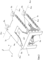
- figure 2 shows the mainland with the parallel links L o , L u arranged on it.
- the links have a truss-like structure made up of individual prisms running in the transverse direction Y.
- the top of the upper link L o and the underside of the lower link L u are largely closed, with both links in the longitudinal direction X on the side facing away from the first block end B 1 having a recess for receiving sections of the load receptor A.
- Via support joints Gs are the handlebars are articulated to the mainland F.
- the support joints are designed as cross spring joints.
- FIG figure 3 shows a schematic representation of the load receiver A. This is connected to the parallel links L o , L u via link joints G R , the support joints and the link joints forming pivot axes A GS and A GR , which in the embodiment according to FIG figure 3 all parallel to each other in the transverse direction Y and are not fully labeled. Also, the load receptor A shows sections with a truss-like structure for weight saving. A middle section A M of the load receiver A protrudes in the longitudinal direction X into the recess in the upper link L o .
- FIG 4 shows the partially broken load receptor A from diagonally below.
- a coupling element Kan engages with it.
- the coupling element has two load joints G L arranged one above the other in the vertical direction Z, which are each designed as cross spring joints and each have a pivot axis A GL running in the transverse direction Y.
- the upper load joint is connected to section A M of load receptor A and is used to receive and transfer a load introduced into load receptor A.
- Arranged between the two load joints of the coupling element K is a web connecting the two joints to one another.
- the lower load link sits in a pocket of a first lever H and engages a first end portion H of the lever H on this.
- the lever A extends in the longitudinal direction X to a second end region H 2 in order to be coupled to a second lever M there.
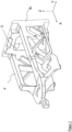
- figure 5 shows the arrangement of the first lever H with a second lever M extending through it.
- the second lever M also extends in the longitudinal direction X from a first end area M1 to a second end area M2 (see 6 ).
- the lever H is provided at its first end region H for support on the mainland (not shown) with two support joints Gs which are one behind the other in the transverse direction Y and which form a common pivot axis A GS .
- the lever H is approximately symmetrical about a central XZ plane, and the rear support joint Gs is in figure 5 hidden by sections of the lever construction.
- the two support joints Gs are designed as cross spring joints (all in the Figures 1 to 9
- the cruciform joints shown each comprise three webs which are arranged one behind the other in the direction of the pivot axis and which connect the two sections which are to be guided in an articulated manner with one another.
- the middle web is inclined by 90° relative to the pivot axis relative to the other two webs).
- the first lever H is penetrated by a free space which runs in the longitudinal direction X and is occupied by the second lever M.
- Both levers are at least partially designed as a framework construction.
- FIG 6 shows from another view how the first lever H is connected at its second end area H 2 via a coupling element K to the first end area M 2 of the second lever M.
- the coupling element K again comprises two load joints arranged one above the other in the height direction Z (of which only the lower one is labeled).
- the two load joints A GL form, analogously to the design of the coupling element in figure 4 , in each case a pivot axis A GL running in the transverse direction Y. Both load joints are connected to each other via an intermediate web. Unlike the coupling element K in figure 4 here the web is interspersed with recesses in order to save weight.
- the lower load joint G L is arranged in a pocket T of the handlebar M.
- the pocket T has two wall sections W which are parallel to one another and which accommodate the lower load hinge G L between them.
- the two wall sections W are connected to one another by a common support section V at their lower end.
- the lower load joint G L acts on this support section V in order to introduce the lever force passed from the first lever H through the coupling element K into the lever M.
- a support joint Gs is provided on the outer side of the two wall sections facing away from the lower load joint, which supports the lever M on the mainland (not shown). figure 6 only shows the front of the two joints).
- an upper support section V protrudes laterally outwards in the transverse direction Y on the outside of each wall section W facing away from the lower load joint G L , which is gripped on its underside by the webs of the support joint Gs designed as a cross spring joint.
- Each wall section W of the pocket T thus has, on opposite sides in the transverse direction Y, two support sections V that are offset from one another in the height direction Z, so that a cross section perpendicular to the longitudinal direction X through each wall section would result in an approximately Z-shaped contour (with sections orthogonal to one another).
- the two support joints Gs on the first end area M of the lever M determine the pivot axis about which the lever can be pivoted relative to the mainland.
- the distance between the common pivot axis A GS of the two supporting joints Gs lying one behind the other in the transverse direction Y and the distance between the pivot axis A GL of the lower load joint G L determines a short lever arm of the lever M. In order to achieve high transmission ratios, the distance should be as small as possible.
- the joints G L , Gs that determine the above-mentioned center distance have a certain extent transversely to their pivot axes (which is formed in particular by the webs of the flexure joint), the pivot axes can be formed very close to one another due to the offset arrangement of the respective joints in the transverse direction Y .
- the upper load joint G L of the coupling element K which is attached to the second end area H 2 of the lever H, protrudes through a recess so far into the lever H that the pivot axis A GL of the upper load joint runs through the upper lever H. This also results in an overall height that is reduced, in particular in height directions H.
- FIG 5 one of the support joints Gs provided on the first end region H1 of the lever H.
- figure 6 shows the second support joint Gs opposite this joint in the transverse direction Y (in figure 6 rightmost).
- a pocket T is also provided there, which extends with a wall section at least on one side of the support joint.
- a support section V protrudes outwards from this wall section in the transverse direction Y in order to be able to accommodate the upwardly protruding webs of the support joint Gs.
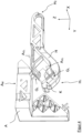
- figure 7 shows the arrangement according to figure 6 , embedded in the mainland F. It can be seen how the two levers M, H project into a recess of the mainland F in the region of their coupling by means of a coupling element K in order to be able to form maximum lever lengths. It can also be seen how the front support joint Gs of the lower lever M is supported on the mainland F.
- the mainland At its rear end in the X-direction, the mainland has a fastening section E 1 in order to arrange a component of the force compensation system thereon, in particular a permanent magnet D. In the X-direction there is another section E 2 which is used to hold the element Q 2 of the position detector Q is provided.
- figure 8 shows the construction according to figure 9 in a tilted view, but without the upper and lower links L o , L u .
- a coil P carried by the lower lever M via an extension bolted to it, which moves relative to a permanent magnet D carried by the mainland F as a function of the weight absorbed by the load receptor A and translated by the levers.
- Coil P and permanent magnet D form elements of an electromagnetic force compensation system, with which the pivoting movement of the lever M is compensated in order to be able to deduce the weight force to be measured from the coil current required for this.
- the coil P and the permanent magnet D are in the longitudinal direction X within an im Load receptor A provided recess arranged to form the shortest possible space in the longitudinal direction X maximum lever lengths or translations can.
- the individual components of the weighing block according to the invention can advantageously penetrate one another in order to thereby reduce installation space.
- penetration can take place in that a first component has a recess into which the other component protrudes.
- the components can also penetrate each other, which is based on figure 10 should be explained.
- Two components 1, 2, which extend in the longitudinal direction X, can be seen there in a cross-section formed transversely to the longitudinal direction X.
- component 1 has individual partial areas T 1
- the cross section of component 2 is made up of the respective partial areas T 2 .
- the cross section of component 1 is encircled by an envelope curve V 1
- the envelope curve V 2 encircles the cross section of component 2.
- the mutual penetration of the two components is characterized in that partial areas of one component are located within the envelope curve of the other component. This enables a stable and particularly space-saving arrangement of the components. Of course, more than two different components can penetrate each other in this way.
- figure 10 also makes it clear that the cross-sectional area composed of the individual partial areas of a component is significantly smaller than the area encircled by the respective envelope curve of this cross-section.
- a lever configured as a framework could have the cross section of component 1, with the individual partial surfaces T 1 corresponding to the sections through the rods, which vary in their dimensions.
- Component 2 could be another truss-lever coupled to the lever, with both levers in the in figure 10 exemplified manner can penetrate.
- figure 10 is only intended to illustrate the penetration principle of components arranged one inside the other, whose cross-sections and partial areas can also be different depending on the requirements.
- figure 11 shows an example of a link L o designed as a framework, which has two support joints Gs on the mainland (not shown) and two link joints G R is articulated to the load receptor, also not shown.
- the truss structure offers high rigidity in all spatial directions at a low weight.
- the material-free space between the bars offers space for other components that could penetrate the handlebars.
- one or more other components of the weighing block can of course also be designed like trusses based on this model.
- FIG. 12a shows an example of a truss-like structure of a component that is made up of individual prisms or is interspersed with prism-shaped recesses.
- An alternative design is in Figure 12b to see in which a cuboid block is interspersed with spherical recesses.
Claims (15)
- Bloc de pesage (B) qui s'étend dans une direction longitudinale (X), dans une direction transversale (Y) orthogonale à la direction longitudinale (X) et dans une direction de hauteur (Z) orthogonale aux deux directions (X, Y), le bloc de pesage (B) comprenanta) une partie fixe (F) destinée à supporter des guidons ou des leviers,b) deux guidons (Lo, Lu), chacun des deux guidons s'étendant dans la direction longitudinale (X) d'une première région d'extrémité à une seconde région d'extrémité opposée à la première extrémité, chaque guidon (Lo, Lu) étant relié à la partie fixe (F) par l'intermédiaire d'au moins une articulation de support (Gs),c) un dispositif de réception de charge (A) destiné à recevoir une force de poids introduite le long de la direction de hauteur (Z), les deux guidons étant reliés respectivement par leur seconde extrémité au dispositif de réception de charge (A) par l'intermédiaire d'au moins une articulation de guidon (GR), de sorte que le dispositif de réception de charge (A) est guidé parallèlement par rapport à la partie fixe dans la direction de hauteur (Z),d) en ce que les composants individuels du bloc de pesage (B) sont construits en couches selon le principe de la fabrication générative (impression 3D) et sont réalisés de manière monolithique et cohérente,e) le bloc de pesage (B) présentant des contre-dépouilles qui sont formées lors de la fabrication générative par des zones dans lesquelles aucune couche de matériau n'est construite,
caractérisé en cef) qu'un premier levier (H) est prévu, lequel s'étend entre une première région d'extrémité (H1) et une seconde région d'extrémité (H2), le premier levier (H) se raccordant au niveau de sa première région d'extrémité (H1) à un élément d'accouplement (K) comprenant au moins une une articulation de charge (GL) pour la transmission d'une force, et le premier levier (H) étant relié à la partie fixe (F) par l'intermédiaire d'une articulation de support (Gs), et aussi bien l'articulation de support (Gs) que l'articulation de charge (GL) formant respectivement un axe de pivotement (AGS, AGL), etg) que l'articulation de charge (GL), pour relier de manière articulée deux sections du bloc de pesage entre elles, est réalisée sous la forme d'une articulation à ressorts croisés, dans laquelle au moins deux barres de matériau relient conjointement la première section à la seconde section, et l'une des barres de matériau formant, dans une projection le long de l'axe de pivotement, un angle (α) avec une autre barre de matériau, avec 45° ≤ α ≤ 135°, de préférence α = 90°. - Bloc de pesage (B) qui s'étend dans une direction longitudinale (X), dans une direction transversale (Y) orthogonale à la direction longitudinale (X) et dans une direction de hauteur (Z) orthogonale aux deux directions (X, Y), le bloc de pesage (B) comprenanta) une partie fixe (F) destinée à soutenir des guidons ou des leviers,b) deux guidons (Lo, Lu), chacun des deux guidons s'étendant dans la direction longitudinale (X) d'une première région d'extrémité à une seconde région d'extrémité opposée à la première extrémité, chaque guidon (Lo, Lu) étant relié à la partie fixe (F) par l'intermédiaire d'au moins une articulation de support (Gs),c) un dispositif de réception de charge (A) destiné à recevoir une force de poids introduite le long de la direction de hauteur (Z), les deux guidons étant reliés respectivement par leur seconde extrémité au dispositif de réception de charge (A) par l'intermédiaire d'au moins une articulation de guidon (GR), de sorte que le dispositif de réception de charge (A) est guidé parallèlement par rapport à la partie fixe dans la direction de hauteur (Z),d) en ce que les composants individuels du bloc de pesage (B) sont construits en couches selon le principe de la fabrication générative (impression 3D) et sont réalisés de manière monolithique et cohérente,e) le bloc de pesage (B) présentant des contre-dépouilles qui sont formées lors de la fabrication générative par des zones dans lesquelles aucune couche de matériau n'est construite,
caractérisé en cef) qu'un premier levier (H) est prévu, lequel s'étend entre une première région d'extrémité (H1) et une seconde région d'extrémité (H2), le premier levier (H) se raccordant au niveau de sa première région d'extrémité (H1) à un élément d'accouplement (K) comprenant au moins une une articulation de charge (GL) pour la transmission d'une force, et le premier levier (H) étant relié à la partie fixe (F) par l'intermédiaire d'une articulation de support (Gs), et aussi bien l'articulation de support (Gs) que l'articulation de charge (GL) formant respectivement un axe de pivotement (AGS, AGL), etg) qu'au moins une articulation de charge (GL) ou une articulation de support (Gs) reliée à un levier (H, M) est bordée sur un côté ou sur les deux côtés, par rapport à la direction de son axe de pivotement, par une section de matériau dudit levier. - Bloc de pesage (B) qui s'étend dans une direction longitudinale (X), dans une direction transversale (Y) orthogonale à la direction longitudinale (X) et dans une direction de hauteur (Z) orthogonale aux deux directions (X, Y), le bloc de pesage (B) comprenanta) une partie fixe (F) destinée à supporter des guidons ou des leviers,b) deux guidons (Lo, Lu), chacun des deux guidons s'étendant dans la direction longitudinale (X) d'une première région d'extrémité à une seconde région d'extrémité opposée à la première extrémité, chaque guidon (Lo, Lu) étant relié à la partie fixe (F) par l'intermédiaire d'au moins une articulation de support (Gs),c) un dispositif de réception de charge (A) destiné à recevoir une force de poids introduite le long de la direction de hauteur (Z), les deux guidons étant reliés respectivement par leur seconde extrémité au dispositif de réception de charge (A) par l'intermédiaire d'au moins une articulation de guidon (GR), de sorte que le dispositif de réception de charge (A) est guidé parallèlement par rapport à la partie fixe dans la direction de hauteur (Z),d) en ce que les composants individuels du bloc de pesage (B) sont construits en couches selon le principe de la fabrication générative (impression 3D) et sont réalisés de manière monolithique et cohérente,e) le bloc de pesage (B) présentant des contre-dépouilles qui sont formées lors de la fabrication générative par des zones dans lesquelles aucune couche de matériau n'est construite,
caractérisé en cef) qu'un premier levier (H) est prévu, lequel s'étend entre une première région d'extrémité (H1) et une seconde région d'extrémité (H2), le premier levier (H) se raccordant au niveau de sa première région d'extrémité (H1) à un élément d'accouplement (K) comprenant au moins une une articulation de charge (GL) pour la transmission d'une force, et le premier levier (H) étant relié à la partie fixe (F) par l'intermédiaire d'une articulation de support (Gs), et aussi bien l'articulation de support (Gs) que l'articulation de charge (GL) formant respectivement un axe de pivotement (AGS, AGL), etg) qu'au moins deux articulations agissant sur le même levier et dont les axes de pivotement ne sont pas alignés se trouvent l'une derrière l'autre dans la direction de leurs axes de pivotement, de sorte que les sections transversales d'articulation formées perpendiculairement à leurs axes de pivotement se recouvrent dans une projection dans la direction des axes de pivotement. - Bloc de pesage (B) qui s'étend dans une direction longitudinale (X), dans une direction transversale (Y) orthogonale à la direction longitudinale (X) et dans une direction de hauteur (Z) orthogonale aux deux directions (X, Y), le bloc de pesage (B) comprenanta) une partie fixe (F) destinée à supporter des guidons ou des leviers,b) deux guidons (Lo, Lu), chacun des deux guidons s'étendant dans la direction longitudinale (X) d'une première région d'extrémité à une seconde région d'extrémité opposée à la première extrémité, chaque guidon (Lo, Lu) étant relié à la partie fixe (F) par l'intermédiaire d'au moins une articulation de support (Gs),c) un dispositif de réception de charge (A) destiné à recevoir une force de poids introduite le long de la direction de hauteur (Z), les deux guidons étant reliés respectivement par leur seconde extrémité au dispositif de réception de charge (A) par l'intermédiaire d'au moins une articulation de guidon (GR), de sorte que le dispositif de réception de charge (A) est guidé parallèlement par rapport à la partie fixe dans la direction de hauteur (Z),d) en ce que les composants individuels du bloc de pesage (B) sont construits en couches selon le principe de la fabrication générative (impression 3D) et sont réalisés de manière monolithique et cohérente,e) le bloc de pesage (B) présentant des contre-dépouilles qui sont formées lors de la fabrication générative par des zones dans lesquelles aucune couche de matériau n'est construite,
caractérisé en cef) qu'un premier levier (H) est prévu, lequel s'étend entre une première région d'extrémité (H1) et une seconde région d'extrémité (H2), le premier levier (H) se raccordant au niveau de sa première région d'extrémité (H1) à un élément d'accouplement (K) comprenant au moins une une articulation de charge (GL) pour la transmission d'une force, et le premier levier (H) étant relié à la partie fixe (F) par l'intermédiaire d'une articulation de support (Gs), et aussi bien l'articulation de support (Gs) que l'articulation de charge (GL) formant respectivement un axe de pivotement (AGS, AGL), etg) que la distance d'axe de pivotement se trouvant dans une direction (X, Y, Z) de deux articulations reliées au même levier est supérieure à zéro et est inférieure à l'extension d'au moins l'une des articulations dans ladite direction. - Bloc de pesage (B) qui s'étend dans une direction longitudinale (X), dans une direction transversale (Y) orthogonale à la direction longitudinale (X) et dans une direction de hauteur (Z) orthogonale aux deux directions (X, Y), le bloc de pesage (B) comprenanta) une partie fixe (F) destinée à supporter des guidons ou des leviers,b) deux guidons (Lo, Lu), chacun des deux guidons s'étendant dans la direction longitudinale (X) d'une première région d'extrémité à une seconde région d'extrémité opposée à la première extrémité, chaque guidon (Lo, Lu) étant relié à la partie fixe (F) par l'intermédiaire d'au moins une articulation de support (Gs),c) un dispositif de réception de charge (A) destiné à recevoir une force de poids introduite le long de la direction de hauteur (Z), les deux guidons étant reliés respectivement par leur seconde extrémité au dispositif de réception de charge (A) par l'intermédiaire d'au moins une articulation de guidon (GR), de sorte que le dispositif de réception de charge (A) est guidé parallèlement par rapport à la partie fixe dans la direction de hauteur (Z),d) en ce que les composants individuels du bloc de pesage (B) sont construits en couches selon le principe de la fabrication générative (impression 3D) et sont réalisés de manière monolithique et cohérente,e) le bloc de pesage (B) présentant des contre-dépouilles qui sont formées lors de la fabrication générative par des zones dans lesquelles aucune couche de matériau n'est construite,
caractérisé en cef) qu'un premier levier (H) est prévu, lequel s'étend entre une première région d'extrémité (H1) et une seconde région d'extrémité (H2), le premier levier (H) se raccordant au niveau de sa première région d'extrémité (H1) à un élément d'accouplement (K) comprenant au moins une une articulation de charge (GL) pour la transmission d'une force, et le premier levier (H) étant relié à la partie fixe (F) par l'intermédiaire d'une articulation de support (Gs), et aussi bien l'articulation de support (Gs) que l'articulation de charge (GL) formant respectivement un axe de pivotement (AGS, AGL), etg) qu'au moins un levier (H, M) présente une poche (T) destinée à recevoir une première articulation. - Bloc de pesage (B) qui s'étend dans une direction longitudinale (X), dans une direction transversale (Y) orthogonale à la direction longitudinale (X) et dans une direction de hauteur (Z) orthogonale aux deux directions (X, Y), le bloc de pesage (B) comprenanta) une partie fixe (F) destinée à supporter des guidons ou des leviers,b) deux guidons (Lo, Lu), chacun des deux guidons s'étendant dans la direction longitudinale (X) d'une première région d'extrémité à une seconde région d'extrémité opposée à la première extrémité, chaque guidon (Lo, Lu) étant relié à la partie fixe (F) par l'intermédiaire d'au moins une articulation de support (Gs),c) un dispositif de réception de charge (A) destiné à recevoir une force de poids introduite le long de la direction de hauteur (Z), les deux guidons étant reliés respectivement par leur seconde extrémité au dispositif de réception de charge (A) par l'intermédiaire d'au moins une articulation de guidon (GR), de sorte que le dispositif de réception de charge (A) est guidé parallèlement par rapport à la partie fixe dans la direction de hauteur (Z),d) en ce que les composants individuels du bloc de pesage (B) sont construits en couches selon le principe de la fabrication générative (impression 3D) et sont réalisés de manière monolithique et cohérente,e) le bloc de pesage (B) présentant des contre-dépouilles qui sont formées lors de la fabrication générative par des zones dans lesquelles aucune couche de matériau n'est construite,
caractérisé en cef) qu'un premier levier (H) est prévu, lequel s'étend entre une première région d'extrémité (H1) et une seconde région d'extrémité (H2), le premier levier (H) se raccordant au niveau de sa première région d'extrémité (H1) à un élément d'accouplement (K) comprenant au moins une une articulation de charge (GL) pour la transmission d'une force, et le premier levier (H) étant relié à la partie fixe (F) par l'intermédiaire d'une articulation de support (Gs), et aussi bien l'articulation de support (Gs) que l'articulation de charge (GL) formant respectivement un axe de pivotement (AGS, AGL), etg) qu'un second levier (M) est prévu, lequel s'étend entre une première région d'extrémité (M1) et une seconde région d'extrémité (M2) et est relié, au niveau de sa première région d'extrémité (M1), par l'intermédiaire d'un élément d'accouplement (K) présentant une articulation de charge (GL), à la seconde région d'extrémité (H2) du premier levier (H) et, par l'intermédiaire d'une articulation de support (Gs), à la partie fixe, et aussi bien l'articulation de support (Gs) que l'articulation de charge (GL) formant respectivement un axe de pivotement. - Bloc de pesage (B) selon la revendication précédente,
caractérisé en ce que l'un des deux leviers (H, M) présente un évidement dans lequel une section de l'autre levier (M, H) est disposée. - Bloc de pesage (B) qui s'étend dans une direction longitudinale (X), dans une direction transversale (Y) orthogonale à la direction longitudinale (X) et dans une direction de hauteur (Z) orthogonale aux deux directions (X, Y), le bloc de pesage (B) comprenanta) une partie fixe (F) destinée à supporter des guidons ou des leviers,b) deux guidons (Lo, Lu), chacun des deux guidons s'étendant dans la direction longitudinale (X) d'une première région d'extrémité à une seconde région d'extrémité opposée à la première extrémité, chaque guidon (Lo, Lu) étant relié à la partie fixe (F) par l'intermédiaire d'au moins une articulation de support (Gs),c) un dispositif de réception de charge (A) destiné à recevoir une force de poids introduite le long de la direction de hauteur (Z), les deux guidons étant reliés respectivement par leur seconde extrémité au dispositif de réception de charge (A) par l'intermédiaire d'au moins une articulation de guidon (GR), de sorte que le dispositif de réception de charge (A) est guidé parallèlement par rapport à la partie fixe dans la direction de hauteur (Z),d) en ce que les composants individuels du bloc de pesage (B) sont construits en couches selon le principe de la fabrication générative (impression 3D) et sont réalisés de manière monolithique et cohérente,e) le bloc de pesage (B) présentant des contre-dépouilles qui sont formées lors de la fabrication générative par des zones dans lesquelles aucune couche de matériau n'est construite,
caractérisé en cef) que le dispositif de réception de charge (L) et/ou la partie fixe (F) sont traversés par un évidement s'étendant dans la direction longitudinale (X), dans lequel évidement au moins une articulation, en particulier une articulation de support (Gs), est disposée. - Bloc de pesage (B) qui s'étend dans une direction longitudinale (X), dans une direction transversale (Y) orthogonale à la direction longitudinale (X) et dans une direction de hauteur (Z) orthogonale aux deux directions (X, Y), le bloc de pesage (B) comprenanta) une partie fixe (F) destinée à supporter des guidons ou des leviers,b) deux guidons (Lo, Lu), chacun des deux guidons s'étendant dans la direction longitudinale (X) d'une première région d'extrémité à une seconde région d'extrémité opposée à la première extrémité, chaque guidon (Lo, Lu) étant relié à la partie fixe (F) par l'intermédiaire d'au moins une articulation de support (Gs),c) un dispositif de réception de charge (A) destiné à recevoir une force de poids introduite le long de la direction de hauteur (Z), les deux guidons étant reliés respectivement par leur seconde extrémité au dispositif de réception de charge (A) par l'intermédiaire d'au moins une articulation de guidon (GR), de sorte que le dispositif de réception de charge (A) est guidé parallèlement par rapport à la partie fixe dans la direction de hauteur (Z),d) en ce que les composants individuels du bloc de pesage (B) sont construits en couches selon le principe de la fabrication générative (impression 3D) et sont réalisés de manière monolithique et cohérente,e) le bloc de pesage (B) présentant des contre-dépouilles qui sont formées lors de la fabrication générative par des zones dans lesquelles aucune couche de matériau n'est construite,
caractérisé en cef) qu'au moins une section d'un levier (H, M) ou d'une articulation (Gs, GR, GL) ou d'un guidon (Lo, Lu), ou de la partie fixe (F) ou du dispositif de réception de charge (A) ou de l'élément d'accouplement (K), de préférence tous les composants du bloc de pesage, sont réalisés sous forme de treillis. - Bloc de pesage (B) qui s'étend dans une direction longitudinale (X), dans une direction transversale (Y) orthogonale à la direction longitudinale (X) et dans une direction de hauteur (Z) orthogonale aux deux directions (X, Y), le bloc de pesage (B) comprenanta) une partie fixe (F) destinée à supporter des guidons ou des leviers,b) deux guidons (Lo, Lu), chacun des deux guidons s'étendant dans la direction longitudinale (X) d'une première région d'extrémité à une seconde région d'extrémité opposée à la première extrémité, chaque guidon (Lo, Lu) étant relié à la partie fixe (F) par l'intermédiaire d'au moins une articulation de support (Gs),c) un dispositif de réception de charge (A) destiné à recevoir une force de poids introduite le long de la direction de hauteur (Z), les deux guidons étant reliés respectivement par leur seconde extrémité au dispositif de réception de charge (A) par l'intermédiaire d'au moins une articulation de guidon (GR), de sorte que le dispositif de réception de charge (A) est guidé parallèlement par rapport à la partie fixe dans la direction de hauteur (Z),d) en ce que les composants individuels du bloc de pesage (B) sont construits en couches selon le principe de la fabrication générative (impression 3D) et sont réalisés de manière monolithique et cohérente,e) le bloc de pesage (B) présentant des contre-dépouilles qui sont formées lors de la fabrication générative par des zones dans lesquelles aucune couche de matériau n'est construite,
caractérisé en cef) qu'au moins deux composants (1, 2) du bloc de pesage forment, dans une coupe transversale à une direction (X, Y, Z), en particulier à la direction longitudinale (X), respectivement une section transversale comportant une surface de section transversale constituée de plusieurs surfaces partielles séparées (T1, T2), et les enveloppes (V1, V2) des deux sections transversales se recouvrant au moins partiellement, et respectivement au moins une surface partielle d'une section transversale se trouvant à l'intérieur de l'enveloppe de l'autre section transversale, et faisant partie des composants : une partie fixe (F), un dispositif de réception de charge (A), un levier (H, M), un élément d'accouplement (K), un guidon, une articulation (GL, GS, GR). - Composant d'un bloc de pesage (B) selon l'une des revendications précédentes, le composant étant un levier (H, M) ou une partie fixe (F) ou un dispositif de réception de charge (A) ou une articulation (GL, GS, GR) ou un guidon (Lo, Lu) ou un élément d'accouplement (K).
- Procédé destiné à la fabrication d'un bloc de pesage (B) monolithique selon l'une des revendications précédentes, les composants individuels étant formés par l'application répétée de couches minces de matériau les unes sur les autres (impression 3D), de préférence dans lequel la structure de matériau d'un composant du bloc de pesage est interrompue par la structure de matériau d'au moins un autre composant.
- Procédé selon la revendication 12, destiné à la fabrication d'au moins un composant monolithique d'un bloc de pesage (B) monolithique selon l'une des revendications 1 à 10, comprenant la fabrication générative (impression 3D) de l'au moins un composant, l'au moins un composant étant un levier (H, M) ou/une partie fixe (F) et/ou un dispositif de réception de charge (A) et/ou une articulation (GL, GS, GR) et/ou un guidon (Lo, Lu) ou un élément d'accouplement (K).
- Bloc de pesage (B) selon l'une des revendications précédentes 1 à 10, caractérisé en ce que le bloc de pesage est formé partiellement ou entièrement à partir de métal, de préférence d'aluminium ou d'un alliage d'aluminium.
- Bloc de pesage (B) selon l'une des revendications 8 à 10,
caractérisé en ce qu'un premier levier (H) est prévu, lequel s'étend entre une première région d'extrémité (H1) et une seconde région d'extrémité (H2), le premier levier (H) se raccordant au niveau de sa première région d'extrémité (H1) à un élément d'accouplement (K) comprenant au moins une une articulation de charge (GL) pour la transmission d'une force, et le premier levier (H) étant relié à la partie fixe (F) par l'intermédiaire d'une articulation de support (Gs), et aussi bien l'articulation de support (Gs) que l'articulation de charge (GL) formant respectivement un axe de pivotement (AGS, AGL).
Applications Claiming Priority (1)
| Application Number | Priority Date | Filing Date | Title |
|---|---|---|---|
| DE102019113001.8A DE102019113001A1 (de) | 2019-05-16 | 2019-05-16 | Monolithischer Wägeblock |
Publications (3)
| Publication Number | Publication Date |
|---|---|
| EP3798588A1 EP3798588A1 (fr) | 2021-03-31 |
| EP3798588C0 EP3798588C0 (fr) | 2023-08-30 |
| EP3798588B1 true EP3798588B1 (fr) | 2023-08-30 |
Family
ID=70977325
Family Applications (1)
| Application Number | Title | Priority Date | Filing Date |
|---|---|---|---|
| EP20174901.7A Active EP3798588B1 (fr) | 2019-05-16 | 2020-05-15 | Bloc de pesage monolithique |
Country Status (6)
| Country | Link |
|---|---|
| US (1) | US11808618B2 (fr) |
| EP (1) | EP3798588B1 (fr) |
| JP (2) | JP7076496B2 (fr) |
| CN (1) | CN111579045B (fr) |
| DE (1) | DE102019113001A1 (fr) |
| PL (1) | PL3798588T3 (fr) |
Families Citing this family (2)
| Publication number | Priority date | Publication date | Assignee | Title |
|---|---|---|---|---|
| DE102020130068A1 (de) * | 2020-11-13 | 2022-05-19 | Wipotec Gmbh | Kraftübertragungselement für eine Waage bzw. Wägezelle |
| EP4009013A1 (fr) * | 2020-12-04 | 2022-06-08 | Mettler-Toledo GmbH | Corps structural d'un capteur de pesage |
Family Cites Families (31)
| Publication number | Priority date | Publication date | Assignee | Title |
|---|---|---|---|---|
| DE3702271A1 (de) | 1987-01-27 | 1988-08-04 | Bizerba Werke Kraut Kg Wilh | Biegekraftaufnehmer, insbesondere fuer waagen |
| DE19859991B4 (de) * | 1998-12-23 | 2009-10-01 | Mettler-Toledo Ag | Kraftmeßvorrichtung, isnbesondere Wägezelle II |
| DE19923207C1 (de) * | 1999-05-20 | 2000-10-12 | Sartorius Gmbh | Wägeaufnehmer |
| DE10326699B3 (de) * | 2003-06-13 | 2005-01-13 | Sartorius Ag | Kompaktes Wägesystem |
| ATE349000T1 (de) * | 2004-02-12 | 2007-01-15 | Mettler Toledo Ag | Wägezellenmodul |
| DE102005005369C5 (de) * | 2005-02-05 | 2010-01-21 | Sartorius Ag | Wägesystem |
| DE102005043820B4 (de) * | 2005-09-13 | 2007-08-23 | Wipotec Wiege- Und Positioniersysteme Gmbh | Hebelgetriebe, insbesondere für einen Wägeaufnehmer einer nach dem Prinzip der elektromagnetischen Kraftkompensation arbeitenden Waage |
| DE202008008459U1 (de) | 2008-06-24 | 2008-08-21 | Sartorius Ag | Wägesystem mit Übersetzungshebel |
| DE102008062742B4 (de) * | 2008-12-17 | 2013-04-11 | Sartorius Weighing Technology Gmbh | Oberschalige Waage |
| DE102009017663B4 (de) | 2009-04-16 | 2013-01-31 | Wipotec Wiege- Und Positioniersysteme Gmbh | Wägezelle |
| DE102010008295A1 (de) * | 2010-02-17 | 2011-08-18 | Dieffenbacher System Automation GmbH, 75031 | Vorrichtung und Verfahren zum Bedrucken von Oberflächen von Werkstoffplatten, insbesondere Holzplatten, mit einer mehrfarbigen Abbildung |
| EP2610596B2 (fr) | 2011-12-30 | 2022-03-30 | WIPOTEC GmbH | Elément de pont pour une balance |
| DE102013103791B4 (de) * | 2013-04-16 | 2015-07-09 | Sartorius Lab Instruments Gmbh & Co. Kg | Monolithisches Wägesystem |
| US9024212B2 (en) | 2013-05-09 | 2015-05-05 | Hyer Industries, Inc. | Load sensing system with flexure plate |
| US20150224743A1 (en) * | 2014-02-11 | 2015-08-13 | General Electric Company | Additively manufactured article |
| US10378976B2 (en) * | 2014-03-31 | 2019-08-13 | The Commonwealth Of Australia, Of The Secretary, Department Of Defence | Balance devices |
| DE202014105467U1 (de) * | 2014-11-13 | 2014-11-20 | Wipotec Wiege- Und Positioniersysteme Gmbh | Parallelogrammlenkerstruktur für eine Waage |
| EP3254305B1 (fr) * | 2015-02-06 | 2023-05-10 | Applied Materials, Inc. | Composants de chambre imprimés par impression 3d configurés pour une contrainte de film plus faible et une température de fonctionnement plus basse |
| JP2018511767A (ja) * | 2015-03-05 | 2018-04-26 | リンデ アクチエンゲゼルシャフトLinde Aktiengesellschaft | プレート式熱交換器用の3dプリントされた加熱面要素 |
| AT517322A1 (de) * | 2015-06-10 | 2016-12-15 | Trodat Gmbh | Stempel und Abdruckeinheit, insbesondere als Ersatzteil für einen Stempel |
| AT518085B1 (de) * | 2015-11-30 | 2017-07-15 | Greiner Perfoam Gmbh | Verfahren zur Herstellung eines Kfz-Innenausstattungsbauteils |
| DE102016106048B4 (de) * | 2016-04-02 | 2024-02-08 | Minebea Intec Aachen GmbH & Co. KG | Wägeaufnehmer |
| WO2017180163A1 (fr) * | 2016-04-15 | 2017-10-19 | Hewlett-Packard Development Company, L.P. | Pièces de cellule de charge imprimées de façon tridimensionnelle |
| DE102016206547A1 (de) * | 2016-04-19 | 2017-10-19 | Siemens Aktiengesellschaft | Verfahren zur modularen additiven Herstellung eines Bauteils und Bauteil |
| FR3053785B1 (fr) * | 2016-07-06 | 2020-07-31 | Crouzet Automatismes | Dispositif apte a detecter une force d’appui |
| CN107244070B (zh) * | 2017-05-18 | 2019-06-11 | 西安交通大学 | 一种基于导电油墨的力传感器芯片及其3d打印制作方法 |
| CN207798244U (zh) | 2017-12-04 | 2018-08-31 | 梅特勒-托利多仪器(上海)有限公司 | 称重传感器及其杠杆 |
| CN108020308B (zh) * | 2017-12-21 | 2020-01-10 | 西安蒜泥电子科技有限责任公司 | 一种应用于人体三维扫描设备的称重模块 |
| EP3502633A1 (fr) * | 2017-12-21 | 2019-06-26 | Mettler-Toledo GmbH | Cellule de pesage monolithique |
| DE102019131101A1 (de) * | 2019-11-18 | 2021-05-20 | Sartorius Lab Instruments Gmbh & Co. Kg | Monolithisches Wägesystem und Verfahren zu dessen Herstellung |
| DE102020102606B4 (de) * | 2020-02-03 | 2022-02-24 | Sartorius Lab Instruments Gmbh & Co. Kg | Verfahren zum Herstellen eines Wägesystems |
-
2019
- 2019-05-16 DE DE102019113001.8A patent/DE102019113001A1/de active Pending
-
2020
- 2020-05-12 JP JP2020083914A patent/JP7076496B2/ja active Active
- 2020-05-15 PL PL20174901.7T patent/PL3798588T3/pl unknown
- 2020-05-15 US US16/875,235 patent/US11808618B2/en active Active
- 2020-05-15 EP EP20174901.7A patent/EP3798588B1/fr active Active
- 2020-05-18 CN CN202010422099.XA patent/CN111579045B/zh active Active
-
2022
- 2022-02-28 JP JP2022029132A patent/JP2022068366A/ja active Pending
Also Published As
| Publication number | Publication date |
|---|---|
| PL3798588T3 (pl) | 2024-03-04 |
| JP2022068366A (ja) | 2022-05-09 |
| EP3798588C0 (fr) | 2023-08-30 |
| EP3798588A1 (fr) | 2021-03-31 |
| US20200408590A1 (en) | 2020-12-31 |
| JP2020187125A (ja) | 2020-11-19 |
| DE102019113001A1 (de) | 2020-11-19 |
| US11808618B2 (en) | 2023-11-07 |
| JP7076496B2 (ja) | 2022-05-27 |
| CN111579045A (zh) | 2020-08-25 |
| CN111579045B (zh) | 2021-12-14 |
Similar Documents
| Publication | Publication Date | Title |
|---|---|---|
| EP3798588B1 (fr) | Bloc de pesage monolithique | |
| DE102005005369C5 (de) | Wägesystem | |
| DE102016106048B4 (de) | Wägeaufnehmer | |
| EP2315697B1 (fr) | Support pour composant structural d'aéronef pouvant être produit selon un procédé de fusion sélective par laser, utilisation et procédé de production | |
| EP2179256A1 (fr) | Capteur de pesee | |
| EP3119546A1 (fr) | Presse servant à fabriquer des ébauches de compact présentant des dimensions prescrites et procédé de fabrication associé | |
| EP2356416B1 (fr) | Plaque de mesure de force | |
| EP1754030A1 (fr) | Securite antisurcharge pour element dynamometrique | |
| EP1743144B1 (fr) | Systeme de pesee etroit, pouvant etre assemble de façon compacte lateralement | |
| EP1924828B1 (fr) | Organe de commande a levier utilise en particulier pour un capteur de pesee d'une balance fonctionnant selon le principe de la compensation de force electromagnetique | |
| EP2610596B1 (fr) | Elément de pont pour une balance | |
| EP3252442B1 (fr) | Articulation mince | |
| EP3252443B1 (fr) | Articulation de minces | |
| EP1054242B1 (fr) | Détecteur de poids | |
| EP1848971B1 (fr) | Systeme de pesee | |
| EP2610595B1 (fr) | Pont de pesage | |
| EP1706713B1 (fr) | Capteur de pesee | |
| EP1643223B2 (fr) | Dispositif de transmission de force pour une balance | |
| DE2917966A1 (de) | Einrichtung zur messung von kraftkomponenten in gelenken | |
| EP2527258B1 (fr) | Procédé de fabrication d'un bras pour véhicule spatial | |
| EP4009013A1 (fr) | Corps structural d'un capteur de pesage | |
| EP4001861A1 (fr) | Élément de transmission de force pour une balance ou un cellule de pesage | |
| DE4402061C1 (de) | Feststehendes Portal für Präzisions-Koordinatenmeßgeräte | |
| DE102008011476B3 (de) | Federgelenksystem in Sandwichbauweise für mehrdimensionalen Taster | |
| WO2008125099A2 (fr) | Structure de bras oscillants parallélépipédique, en particulier structure de bras oscillants parallélépipédique monolithique pour dispositif de pesée |
Legal Events
| Date | Code | Title | Description |
|---|---|---|---|
| PUAI | Public reference made under article 153(3) epc to a published international application that has entered the european phase |
Free format text: ORIGINAL CODE: 0009012 |
|
| STAA | Information on the status of an ep patent application or granted ep patent |
Free format text: STATUS: THE APPLICATION HAS BEEN PUBLISHED |
|
| AK | Designated contracting states |
Kind code of ref document: A1 Designated state(s): AL AT BE BG CH CY CZ DE DK EE ES FI FR GB GR HR HU IE IS IT LI LT LU LV MC MK MT NL NO PL PT RO RS SE SI SK SM TR |
|
| AX | Request for extension of the european patent |
Extension state: BA ME |
|
| STAA | Information on the status of an ep patent application or granted ep patent |
Free format text: STATUS: REQUEST FOR EXAMINATION WAS MADE |
|
| 17P | Request for examination filed |
Effective date: 20210929 |
|
| RBV | Designated contracting states (corrected) |
Designated state(s): AL AT BE BG CH CY CZ DE DK EE ES FI FR GB GR HR HU IE IS IT LI LT LU LV MC MK MT NL NO PL PT RO RS SE SI SK SM TR |
|
| STAA | Information on the status of an ep patent application or granted ep patent |
Free format text: STATUS: EXAMINATION IS IN PROGRESS |
|
| 17Q | First examination report despatched |
Effective date: 20220429 |
|
| GRAP | Despatch of communication of intention to grant a patent |
Free format text: ORIGINAL CODE: EPIDOSNIGR1 |
|
| STAA | Information on the status of an ep patent application or granted ep patent |
Free format text: STATUS: GRANT OF PATENT IS INTENDED |
|
| INTG | Intention to grant announced |
Effective date: 20230502 |
|
| GRAS | Grant fee paid |
Free format text: ORIGINAL CODE: EPIDOSNIGR3 |
|
| GRAA | (expected) grant |
Free format text: ORIGINAL CODE: 0009210 |
|
| STAA | Information on the status of an ep patent application or granted ep patent |
Free format text: STATUS: THE PATENT HAS BEEN GRANTED |
|
| AK | Designated contracting states |
Kind code of ref document: B1 Designated state(s): AL AT BE BG CH CY CZ DE DK EE ES FI FR GB GR HR HU IE IS IT LI LT LU LV MC MK MT NL NO PL PT RO RS SE SI SK SM TR |
|
| REG | Reference to a national code |
Ref country code: GB Ref legal event code: FG4D Free format text: NOT ENGLISH |
|
| REG | Reference to a national code |
Ref country code: CH Ref legal event code: EP |
|
| REG | Reference to a national code |
Ref country code: DE Ref legal event code: R096 Ref document number: 502020004930 Country of ref document: DE |
|
| REG | Reference to a national code |
Ref country code: IE Ref legal event code: FG4D Free format text: LANGUAGE OF EP DOCUMENT: GERMAN |
|
| U01 | Request for unitary effect filed |
Effective date: 20230929 |
|
| U07 | Unitary effect registered |
Designated state(s): AT BE BG DE DK EE FI FR IT LT LU LV MT NL PT SE SI Effective date: 20231009 |
|
| PG25 | Lapsed in a contracting state [announced via postgrant information from national office to epo] |
Ref country code: GR Free format text: LAPSE BECAUSE OF FAILURE TO SUBMIT A TRANSLATION OF THE DESCRIPTION OR TO PAY THE FEE WITHIN THE PRESCRIBED TIME-LIMIT Effective date: 20231201 |
|
| PG25 | Lapsed in a contracting state [announced via postgrant information from national office to epo] |
Ref country code: IS Free format text: LAPSE BECAUSE OF FAILURE TO SUBMIT A TRANSLATION OF THE DESCRIPTION OR TO PAY THE FEE WITHIN THE PRESCRIBED TIME-LIMIT Effective date: 20231230 |
|
| PG25 | Lapsed in a contracting state [announced via postgrant information from national office to epo] |
Ref country code: RS Free format text: LAPSE BECAUSE OF FAILURE TO SUBMIT A TRANSLATION OF THE DESCRIPTION OR TO PAY THE FEE WITHIN THE PRESCRIBED TIME-LIMIT Effective date: 20230830 Ref country code: NO Free format text: LAPSE BECAUSE OF FAILURE TO SUBMIT A TRANSLATION OF THE DESCRIPTION OR TO PAY THE FEE WITHIN THE PRESCRIBED TIME-LIMIT Effective date: 20231130 Ref country code: IS Free format text: LAPSE BECAUSE OF FAILURE TO SUBMIT A TRANSLATION OF THE DESCRIPTION OR TO PAY THE FEE WITHIN THE PRESCRIBED TIME-LIMIT Effective date: 20231230 Ref country code: HR Free format text: LAPSE BECAUSE OF FAILURE TO SUBMIT A TRANSLATION OF THE DESCRIPTION OR TO PAY THE FEE WITHIN THE PRESCRIBED TIME-LIMIT Effective date: 20230830 Ref country code: GR Free format text: LAPSE BECAUSE OF FAILURE TO SUBMIT A TRANSLATION OF THE DESCRIPTION OR TO PAY THE FEE WITHIN THE PRESCRIBED TIME-LIMIT Effective date: 20231201 |
|
| PG25 | Lapsed in a contracting state [announced via postgrant information from national office to epo] |
Ref country code: ES Free format text: LAPSE BECAUSE OF FAILURE TO SUBMIT A TRANSLATION OF THE DESCRIPTION OR TO PAY THE FEE WITHIN THE PRESCRIBED TIME-LIMIT Effective date: 20230830 |
|
| PG25 | Lapsed in a contracting state [announced via postgrant information from national office to epo] |
Ref country code: SM Free format text: LAPSE BECAUSE OF FAILURE TO SUBMIT A TRANSLATION OF THE DESCRIPTION OR TO PAY THE FEE WITHIN THE PRESCRIBED TIME-LIMIT Effective date: 20230830 Ref country code: RO Free format text: LAPSE BECAUSE OF FAILURE TO SUBMIT A TRANSLATION OF THE DESCRIPTION OR TO PAY THE FEE WITHIN THE PRESCRIBED TIME-LIMIT Effective date: 20230830 Ref country code: ES Free format text: LAPSE BECAUSE OF FAILURE TO SUBMIT A TRANSLATION OF THE DESCRIPTION OR TO PAY THE FEE WITHIN THE PRESCRIBED TIME-LIMIT Effective date: 20230830 Ref country code: CZ Free format text: LAPSE BECAUSE OF FAILURE TO SUBMIT A TRANSLATION OF THE DESCRIPTION OR TO PAY THE FEE WITHIN THE PRESCRIBED TIME-LIMIT Effective date: 20230830 Ref country code: SK Free format text: LAPSE BECAUSE OF FAILURE TO SUBMIT A TRANSLATION OF THE DESCRIPTION OR TO PAY THE FEE WITHIN THE PRESCRIBED TIME-LIMIT Effective date: 20230830 |
|
| PGFP | Annual fee paid to national office [announced via postgrant information from national office to epo] |
Ref country code: GB Payment date: 20240311 Year of fee payment: 5 |
|
| U20 | Renewal fee paid [unitary effect] |
Year of fee payment: 5 Effective date: 20240326 |
|
| U1N | Appointed representative for the unitary patent procedure changed [after the registration of the unitary effect] |
Representative=s name: EDER SCHIESCHKE & PARTNER MBB; DE |