EP3798588B1 - Monolithic weighing block - Google Patents
Monolithic weighing block Download PDFInfo
- Publication number
- EP3798588B1 EP3798588B1 EP20174901.7A EP20174901A EP3798588B1 EP 3798588 B1 EP3798588 B1 EP 3798588B1 EP 20174901 A EP20174901 A EP 20174901A EP 3798588 B1 EP3798588 B1 EP 3798588B1
- Authority
- EP
- European Patent Office
- Prior art keywords
- joint
- lever
- end portion
- weighing block
- load
- Prior art date
- Legal status (The legal status is an assumption and is not a legal conclusion. Google has not performed a legal analysis and makes no representation as to the accuracy of the status listed.)
- Active
Links
- 238000005303 weighing Methods 0.000 title claims description 108
- 239000000463 material Substances 0.000 claims description 70
- 230000008878 coupling Effects 0.000 claims description 40
- 238000010168 coupling process Methods 0.000 claims description 40
- 238000005859 coupling reaction Methods 0.000 claims description 40
- 238000004519 manufacturing process Methods 0.000 claims description 34
- 238000010146 3D printing Methods 0.000 claims description 30
- 239000000654 additive Substances 0.000 claims description 20
- 230000000996 additive effect Effects 0.000 claims description 20
- 238000000034 method Methods 0.000 claims description 8
- 229910000838 Al alloy Inorganic materials 0.000 claims description 2
- 229910052782 aluminium Inorganic materials 0.000 claims description 2
- XAGFODPZIPBFFR-UHFFFAOYSA-N aluminium Chemical compound [Al] XAGFODPZIPBFFR-UHFFFAOYSA-N 0.000 claims description 2
- 229910052751 metal Inorganic materials 0.000 claims description 2
- 239000002184 metal Substances 0.000 claims description 2
- 230000001427 coherent effect Effects 0.000 claims 9
- 238000013461 design Methods 0.000 description 21
- 230000008901 benefit Effects 0.000 description 14
- 230000015572 biosynthetic process Effects 0.000 description 7
- 238000003754 machining Methods 0.000 description 7
- 238000010276 construction Methods 0.000 description 6
- 230000035515 penetration Effects 0.000 description 5
- 238000012545 processing Methods 0.000 description 5
- 238000005452 bending Methods 0.000 description 3
- 230000005540 biological transmission Effects 0.000 description 3
- 230000003287 optical effect Effects 0.000 description 3
- 238000005520 cutting process Methods 0.000 description 2
- 230000003628 erosive effect Effects 0.000 description 2
- 238000009434 installation Methods 0.000 description 2
- 238000003801 milling Methods 0.000 description 2
- 239000007787 solid Substances 0.000 description 2
- 238000012546 transfer Methods 0.000 description 2
- 239000004020 conductor Substances 0.000 description 1
- 238000011161 development Methods 0.000 description 1
- 238000005553 drilling Methods 0.000 description 1
- 230000000694 effects Effects 0.000 description 1
- 238000005516 engineering process Methods 0.000 description 1
- 230000007246 mechanism Effects 0.000 description 1
- 230000000149 penetrating effect Effects 0.000 description 1
- 238000012805 post-processing Methods 0.000 description 1
- 238000007639 printing Methods 0.000 description 1
- 230000008569 process Effects 0.000 description 1
- 230000035945 sensitivity Effects 0.000 description 1
- 238000000926 separation method Methods 0.000 description 1
- 239000011343 solid material Substances 0.000 description 1
- 238000012360 testing method Methods 0.000 description 1
- 230000008646 thermal stress Effects 0.000 description 1
- 238000013519 translation Methods 0.000 description 1
- 230000014616 translation Effects 0.000 description 1
Images


Classifications
-
- G—PHYSICS
- G01—MEASURING; TESTING
- G01G—WEIGHING
- G01G21/00—Details of weighing apparatus
- G01G21/24—Guides or linkages for ensuring parallel motion of the weigh-pans
-
- B—PERFORMING OPERATIONS; TRANSPORTING
- B22—CASTING; POWDER METALLURGY
- B22F—WORKING METALLIC POWDER; MANUFACTURE OF ARTICLES FROM METALLIC POWDER; MAKING METALLIC POWDER; APPARATUS OR DEVICES SPECIALLY ADAPTED FOR METALLIC POWDER
- B22F5/00—Manufacture of workpieces or articles from metallic powder characterised by the special shape of the product
- B22F5/10—Manufacture of workpieces or articles from metallic powder characterised by the special shape of the product of articles with cavities or holes, not otherwise provided for in the preceding subgroups
-
- B—PERFORMING OPERATIONS; TRANSPORTING
- B33—ADDITIVE MANUFACTURING TECHNOLOGY
- B33Y—ADDITIVE MANUFACTURING, i.e. MANUFACTURING OF THREE-DIMENSIONAL [3-D] OBJECTS BY ADDITIVE DEPOSITION, ADDITIVE AGGLOMERATION OR ADDITIVE LAYERING, e.g. BY 3-D PRINTING, STEREOLITHOGRAPHY OR SELECTIVE LASER SINTERING
- B33Y10/00—Processes of additive manufacturing
-
- B—PERFORMING OPERATIONS; TRANSPORTING
- B33—ADDITIVE MANUFACTURING TECHNOLOGY
- B33Y—ADDITIVE MANUFACTURING, i.e. MANUFACTURING OF THREE-DIMENSIONAL [3-D] OBJECTS BY ADDITIVE DEPOSITION, ADDITIVE AGGLOMERATION OR ADDITIVE LAYERING, e.g. BY 3-D PRINTING, STEREOLITHOGRAPHY OR SELECTIVE LASER SINTERING
- B33Y80/00—Products made by additive manufacturing
-
- G—PHYSICS
- G01—MEASURING; TESTING
- G01G—WEIGHING
- G01G7/00—Weighing apparatus wherein the balancing is effected by magnetic, electromagnetic, or electrostatic action, or by means not provided for in the preceding groups
- G01G7/02—Weighing apparatus wherein the balancing is effected by magnetic, electromagnetic, or electrostatic action, or by means not provided for in the preceding groups by electromagnetic action
-
- G—PHYSICS
- G01—MEASURING; TESTING
- G01G—WEIGHING
- G01G21/00—Details of weighing apparatus
- G01G21/14—Beams
Definitions
- the present invention relates to a monolithic weighing block and a method for its manufacture.
- Monolithic weighing blocks for load cells are known from the prior art. They comprise one or more links and further components of a lever mechanism connected to them in one piece, for example parallel links, a load receiver and a section designated as the mainland. "venue” refers to an area of the weighing block that essentially remains stationary during operation and is used to form the support points or pivot points of levers. A component of the electromagnetic force compensation (usually a permanent magnet), or a position detector, is also carried by the land.
- the monolithic design avoids thermal stresses, and there is no production work involved in assembling individual components of the weighing block.
- the processing of such a weighing block is not arbitrarily possible, since individual components can lie one behind the other in a first direction and have to be separated from one another by appropriate cuts perpendicular to this direction (undercuts).
- the removal of material from the monobloc can therefore only take place there or only from such a direction in which another component does not impede the access of the tool.
- the material that has not been removed, but is functionally superfluous gives the monobloc unnecessary weight, and the production of undercuts is expensive.
- the manufacture of the monoblock structure is limited to the processing of a three-dimensional body from which material is specifically removed, for example by milling, eroding or drilling.
- the remaining material areas form individual, interconnected elements of the monoblock. Since the removal of material is not possible at random positions within the monoblock, the scope for designing the individual elements, in particular for achieving the necessary rigidity with the lowest possible weight, is also limited.
- a monolithic weighing block is known as a bridge element, in which a load sensor acts on two levers which, at a common coupling point, can introduce a force into another lever or into a component of a force compensation system.
- the manufacture of the weighing block is comparatively simple since the block can apparently be completely machined from two opposite sides.
- the DE 20 2014 105467 U1 discloses a monolithic parallelogram linkage structure for a scale, wherein at least one of the parallelogram linkages has a recess through which a portion of the so-called mainland protrudes. This increases the rigidity of the construction.
- the formation of such a monoblock is complicated and expensive due to at least one undercut existing in the area of the recess.
- WO 2017/180163 A1 shows a printed portion of a load cell containing a series of strain gauges.
- Strain gauges are only suitable for selected applications in weighing technology which, for example, cannot use the precision advantages of electromagnetic force compensation.
- the object of the invention was therefore to offer a monobloc and a method for its production, with which this disadvantage can be overcome.
- a weighing block according to the invention extends in a longitudinal direction X, a transverse direction Y orthogonal thereto and a vertical direction Z orthogonal to these two directions. Parts of a force compensation system can also be attached to the mainland.
- the weighing block has two links which extend in the longitudinal direction X and are each connected to the mainland at their first end via a support joint. At their second end opposite the first end, the two links act on a common load receiver, which is guided parallel to the mainland by means of the links in the vertical direction Z.
- the load receptor is used to absorb a weight force introduced in the height direction Z.
- Such a system which in its simplest form manages without force-translating levers, is referred to as a directly supporting system, whereby the movement of the load receptor caused by a weight force is compensated by an opposing force that is generated via a force compensation system.
- a coil as part of this Force compensation system can then be arranged directly on the load receptor.
- a preferred embodiment of the weighing block comprises at least one first lever, which extends (preferably in the longitudinal direction X) between a first end area and a second end area (this direction of extension, along which the lever forms lever arms for changing forces, can also be referred to as the main direction of extension) .
- the lever is connected to the load receiver via a coupling element in order to ensure that a force is transmitted from the load receiver to the lever.
- the coupling element comprises at least one load joint, so that a section of the coupling element can be pivoted about a pivot axis formed by the load joint relative to the lever or to the load receiver.
- the first lever is also connected to the mainland via a support joint, the support joint also forming a pivot axis.
- the embodiment with at least one lever can be produced particularly well by means of 3D printing, since the aforementioned advantages have a full impact here.
- support joint further refers to joints that connect a movable part of the monobloc, in particular a lever or a link, to the mainland or support it. Those joints are to be referred to as “link joints” via which the links are connected to the load receptor. Two movable sections of the weighing block are connected to one another via a "load joint". In particular, the load receiver is connected to one end of a lever via one or more load links, and levers are also connected to one another via load links.
- a load joint is usually part of a coupling element.
- All of these joints each form a pivot axis about which the two sections connected to one another via the joint can be pivoted relative to one another.
- a particularly preferred embodiment of the invention provides that a load joint is designed as a cross spring joint.
- the two sections to be connected to one another in an articulated manner are connected to one another via at least two material webs which preferably do not touch one another in the region of the pivot axis and one of the material webs forming an angle ( ⁇ : # 0°) with the other material web in a projection along the pivot axis .
- the pivot axis is generated here by two material webs lying one behind the other in the axial direction and crossing one another.
- the crossing angle is preferably in the range 45° ⁇ 135°, most preferably exactly 90°.
- a load joint via which a force is introduced into the lever at a lever end region, is expediently arranged in the longitudinal direction of the lever very close to a support joint supporting the lever, in order to be able to achieve a short lever arm or a sufficiently high leverage ratio, and the pivot axis both joints run parallel.
- the design of the load joint as a cross spring joint stands in the way of the design of the closely adjacent support joint as long as the two joints are produced in the conventional manner, namely by removing material from a monolithic block. Joints are usually formed there by boreholes in the direction of the pivot axis, the diameter of which determines the minimum distance from an adjacent further joint. A cross spring joint produced in this way could only be formed at a smaller center distance to another joint if the two joints were offset one behind the other in the axial direction. But then the bores of one joint penetrate the installation space of the other joint, which could only be prevented by complex undercuts.
- the generative structure of the weighing block according to the invention allows the formation of support joint and load joint at a small distance from each other, while at the same time the advantages of the cross spring joint can be used for the load joint.
- This has a particularly advantageous effect if the support joint of the lever provided on the same end region of the lever as the load joint is designed as a cross spring joint of the aforementioned type. Viewed along their pivot axes (running parallel to one another), both joints lie one behind the other, and their extension transversely to the respective pivot axis is then greater than the distance between the pivot axes that defines the length of the lever arm.
- a coupling element which serves to transmit force between two levers or a lever and the load receiver, comprises at least one, preferably two, flexural joints of the aforementioned type, which are spaced apart from one another by a material web that transfers the lever force.
- the joints can be arranged offset one behind the other or side by side/on top of one another, viewed along their parallel pivot axes.
- 3D printing also allows the arrangement of one or two flexure joints (with their associated undercuts) at a close distance from one another on a coupling element, with the formation of a coupling element with at least one flexure joint also independently of this bringing the advantage of a pivot axis other than via a thin spot to define and to provide this special design on a load joint.
- This design of a coupling element according to the invention is not necessarily coupled to a weighing block according to the invention and also offers the advantages mentioned, preferably also separately protectable, independently of this.
- a further advantageous embodiment of the invention provides that the pivot axes of the support joints or link joints arranged on the links lie on the corner points of a parallelogram.
- the links then lie one above the other in the form of an upper and a lower link in the Z direction and extend orthogonally in addition in the longitudinal direction X between the load receptor and the moon (other spatial arrangements are also conceivable).
- This arrangement makes it possible in an advantageous manner to extend the mainland between the links in order to be able to form further support points.
- a further advantageous embodiment of the invention provides that at least one load joint or support joint connected to a lever, viewed in the direction of its pivot axis, is bordered on one side, preferably on both sides, by a material section of this lever.
- the lever then also extends to the side of the joint (seen, for example, in the transverse direction Y) and can have a Z dimension there that is sufficient for its desired rigidity.
- the two elements of the weighing block to be connected to each other by the joint can be arranged at least partially or completely one behind the other in the direction of the pivot axis, so that in this area the total height of the two elements with the joint in between is less than the sum of the heights of the individual elements and the joint.
- a lever to be pivoted about a Y-axis for example, can be supported on the mainland via a support joint, which is located essentially in front of or behind this lever in the Y-direction. In the prior art, the lever always runs in the X or Z direction at a distance past the pivot axis, since (preferably narrow) undercuts would be required for the design according to the invention, which are virtually impossible to produce by machining.
- a further advantageous embodiment of the invention provides that at least two joints acting on the same lever are arranged one behind the other in the direction of their mutually spaced pivot axes in such a way that the joint cross-sections formed perpendicularly to their pivot axes overlap in a projection in the direction of the pivot axes.
- pivot axis of a joint according to the invention can also move through the element guided by this joint allows a further advantageous embodiment, according to which at least one lever has a pocket for receiving a joint connected to this lever.
- the pocket thus encloses the joint at least on one side and protects it from unwanted impact or dirt.
- the arrangement of a pocket formed by a lever with a monolithic joint connecting the lever pivotally therein can hardly be produced with conventional machining processes.
- the pocket comprises at least one wall section from which a first support section protrudes on one side for connection to the joint, for example in that two crossed webs of a flexural joint engage there.
- a further support section can protrude on the other side of the wall section in order to connect elements of a further joint. It is conceivable, for example, that, viewed in the transverse direction Y, a support joint is formed on one side of a pocket wall of a lever, which supports the lever on the mainland.
- the pocket wall then extends approximately along an X-Z plane.
- the support joint acts on the lever side (for example from below) on the support section, which protrudes laterally in the transverse direction Y from an upper area of the pocket wall.
- the joint extends essentially laterally next to or along the pocket wall and its pivot axis runs in the transverse direction Y.
- the coupling element On the other side of the pocket wall, diametrically opposite the first support section, another support section protrudes from a lower area of the wall Transverse direction Y (opposite to the support section on the other side) from which is intended to form the lower point of application of a coupling element.
- the coupling element has a load joint which is to be connected to the further support section and which, starting from this support section, extends upwards along the pocket wall on this side and whose pivot axis in turn runs in the transverse direction Y.
- a joint is then arranged on both sides of the pocket wall, which articulation acts on a support section projecting on different sides of the pocket wall.
- the two support sections thus form an approximately "Z"-shaped cross-section with the pocket wall, with sections running orthogonally to one another.
- the pivot axes of the two joints can be very close to one another in order to generate a very high lever ratio, and at the same time the lever can develop high flexural rigidity against bending moments around the Y-axis, for example due to the height of the pocket wall.
- the two joints are seen in the Y-direction, in front of and behind the pocket wall, preferably at a small Y-distance to the pocket wall, and the respective lateral extension of each joint transversely to its pivot axis can the formation of the other joint, differently than with the known cutting methods in the prior art, do not limit.
- At least one further lever is provided, which essentially has the same purpose as the first lever, in order to achieve an even higher transmission ratio for the weight force introduced via the load receptor by connecting both levers in series than with just one leverage is possible. More than two levers can also be connected in series for this purpose, with a lever supported in the middle being able to transmit the force in an unchanged amount.
- the further lever extends between a first end area and a second end area, it being possible for the direction of extent to correspond to the longitudinal direction X or the direction of extent of the first lever.
- a first lever could extend in the longitudinal direction X, while a further lever coupled to it extends obliquely or orthogonally, for example in the transverse direction Y or height direction Z.
- the coupling elements connecting the levers to one another then have two joints whose pivot axes no longer run parallel.
- the further lever is connected at its first end area via a coupling element having a load joint to the second end area of the first lever and also via a support joint to the mainland.
- the additional lever can either be coupled to an additional lever or carry a component of the force compensation system; it is then considered the "last" lever.
- the second lever extends essentially in the same direction as the first lever coupled to it, 3D printing offers advantageous options for arranging or designing the levers in a space-saving manner.
- one of the two levers could have a recess into which a section of the respective other lever protrudes.
- the levers can penetrate each other partially or completely, thus enabling a space-saving design.
- the first lever could have a recess which extends in the longitudinal direction X and is open upwards and/or downwards in the vertical direction Z and which the lever encloses on both sides in the transverse direction Y. A portion of the second lever or other component of the weighing block may extend through this recess.
- both levers can have a large area moment of inertia and thus a large rigidity in relation to bending form the Y-direction, for which a certain extent in the height direction Z is required.
- the levers can lie one behind the other or one inside the other in the transverse direction Y.
- Conventional monoblocks with such levers can only be produced with difficulty or not at all, since the separation of the levers in the transverse direction Y is only possible by means of a tool fed in the vertical direction Z.
- a particular embodiment of the invention provides that the monoblock comprises at least two levers which penetrate one another in such a way that they run through a volume section of the monoblock together.
- the particular advantage of 3D printing in connection with a monolithic weighing block is that the levers of a monoblock, especially in connection with the electromagnetic force compensation, only perform a virtual movement, since every lever deflection is immediately corrected by the force compensation system In fact, levers do not move relative to each other, but have the freedom of movement to do so. Since the levers do not perform any real pivoting movement and accordingly do not require any space for this, they can be designed lying one inside the other in such a way that a first lever is closely adjacent or surrounded for the most part or completely by a second lever.
- a first lever would be conceivable, for example, which is designed as a framework around an elongated interior running in the direction of extension of the lever. The second lever is partially or completely arranged in the interior space of the first lever.
- individual sections or rods of the first lever can also pass through the interior space in order to make this lever stable. It only has to be ensured that the sections or rods of the second lever do not collide with the first lever. Since the levers do not perform any real pivoting movement, the individual sections of the two levers can be designed to lie very closely together, for example with distances of less than 1000 or 500 ⁇ m.
- the individual sections or rods of each lever can extend in all spatial directions or at an angle to or in a curved shape to the necessary achieve leverage.
- the levers can interpenetrate inseparably in that sections of one lever which are attached to one another and form a closed material chain lead through a corresponding material chain of the other lever.
- the components of the weighing block can also have a truss structure with the thinnest possible walls, formed from regular polygons, for example prisms, which penetrate the component in one or more directions.
- Material-free areas can have the shape of regular geometric bodies (cuboids, pyramids, spheres, prisms, etc.).
- At least two components of the weighing block expediently form a cross-section with a cross-sectional area consisting of several separate sub-areas in a section transverse to a direction X, Y, Z, in particular to the longitudinal direction X, with the envelope curves of the two cross-sections at least partially overlapping, and wherein in each case at least one partial area of one cross section lies within the envelope of the other cross section.
- the following components are particularly suitable here: mainland, load receptor, lever, coupling element, link or joint.
- envelope curve here means that lateral boundary of a cross section which connects the respective outermost points of the cross section with one another in the manner of a rubber band wrapped around the cross section. It is clear from this that material sections of one component can extend through material sections of the other component and at the same time be surrounded laterally by the latter. The space-saving arrangement of the components one inside the other is particularly easy.
- the interpenetration need not be such that one lever is located entirely within the other lever. Partial penetration is also possible in such a way that the volume circumscribed by one lever partially protrudes into the volume circumscribed by the other lever. This reduces the volume required to form the weighing block and, in particular, its weight.
- the offshore extends in the longitudinal direction X, starting from a first end of the block, between the parallel links and/or through the load receptor.
- the extension through the load receptor offers the advantage of being able to support components of the force compensation system beyond the load receptor, such as a permanent magnet or elements of a position detector.
- the mainland which extends into the area of the load receiver, also makes it possible to form support points for levers within the space circumscribed by the load receiver. This means that the levers from the load receptor to the first end of the block can be as long as possible and are not limited to the space available between these two components.
- the load receiver in an area between the upper and lower parallel link so that they cover the load receiver in the height direction Z.
- the links can then be designed with the maximum length and the load receiver lies essentially within the corner points of the parallelogram, which is formed by the pivot axes of the link joints, seen in the transverse direction Y. (This design of the load receptor is not necessarily linked to a weighing block according to the invention and also offers the advantages mentioned, preferably also separately protectable, independently of this.)
- the generative design of the weighing block according to the invention also allows a lever to be bordered on both sides, for example in the transverse direction Y, by a further lever which in turn is bordered on both sides by the mainland F in the same direction.
- the levers are therefore laterally bordered between sections of the mainland and are at the same time particularly well protected given the reduced overall height of the weighing block.
- the cruciform joint described above can also be produced in a preferred further development by means of the generative design according to the invention.
- At least three material webs jointly connect a first section to a second section in an articulated manner, with at least one of the material webs forming an angle ( ⁇ ) with at least two other material webs in a projection along the pivot axis.
- at least three material webs are formed here, with the central web preferably being inclined by the angle ( ⁇ ) relative to the other two webs which are directed in the same direction.
- the angle again obeys the condition 45° ⁇ 135°, most preferably it is 90°.
- At least one section of a lever or link or a joint or the mainland or the load receiver or a coupling element is preferably designed as a framework.
- the entire component is preferably designed as a framework, with the entire weighing block most preferably having such a structure. This allows the weight of the weighing block to be reduced to a minimum, while the truss construction ensures the necessary rigidity of the components.
- the mutual penetration described above for two levers can also be implemented for any other, functionally similar or different components of the weighing block.
- the term "bar structure" is to be used here as a representative for structures that are composed of several individual material sections, with longitudinal forces occurring mainly in the individual material sections, but little or no bending moments.
- the 3D printing of the weighing block according to the invention enables the formation of the individual Components with little material with high rigidity and in a space-saving arrangement relative to each other.
- An embodiment according to the invention is therefore characterized in that the cross-sectional area of at least 50%, preferably more than 80% of all cross-sections placed perpendicular to its main direction of extension by a lever is smaller than the area encircled by the envelope of the respective cross-section.
- the generative creation of the weighing block is not limited to the block as a whole.
- the advantages of 3D printing that were surprisingly found for the components of a weighing block also apply to each of the components themselves.
- the subject matter of the invention is therefore also a component of a weighing block produced in this way and the production of the component as such using 3D printing.
- the method according to the invention for producing the components of the weighing block or the weighing block as a whole is based on forming the individual components by repeatedly applying thin layers of material to one another (3D printing).
- the block is preferably gradually built up in thin layers, starting from a first end such as the first block end, for example in the longitudinal direction X. Material-free areas within the layers form gaps or undercuts that separate the individual components from one another.
- a component is preferably produced “simultaneously” with the production of other components, “simultaneously” meaning that all material regions of a specific layer or at a specific layer height are formed first before the next higher layer is applied.
- the material build-up of one component is thus interrupted by the material build-up of at least one other component if both components require material build-up at the same layer height.
- both components require material build-up at the same layer height.
- any material that meets the requirements for high-precision 3-D printing on the one hand and the requirements for the usual material behavior of monolithic weighing blocks on the other can be used as the material for the weighing block.
- the monolithic design of the weighing block does not rule out the use of different materials for different areas or components of the weighing block, which can nevertheless be monolithically connected to one another.
- a different material could be selected for the mainland, which is particularly stressed in terms of rigidity, than for the load receptor, whose flexural rigidity may be of secondary importance.
- electrically conductive material for example to print a coil arranged on the last lever or connections to position detectors or other sensors.
- the weighing block is made partially or entirely of metal, preferably aluminum or an aluminum alloy.
- the weighing block according to the invention is produced as a 3-D print, the post-processing that may be required with cutting tools is not ruled out.
- FIG 9 shows a schematic side view of a complete weighing block B according to the invention.
- the weighing block B extends in a longitudinal direction X, a transverse direction Y orthogonal thereto, directed into the plane of the drawing, and a vertical direction Z, which is in turn orthogonal to both directions.
- a first (in figure 9 left) Block end B 1 is designed as mainland F over the entire Z height.
- the mainland F extends at a reduced height, starting from the first block end B 1 , in the longitudinal direction X to the right in the direction of the second block end B 2 .
- An upper and a lower parallel link L o , L u act on an upper and a lower section of the first block end B 1 via two support joints Gs arranged one behind the other in the transverse direction Y on the mainland F, with the pivot axes formed by the link joints running in the transverse direction Y (and are unspecified).
- the parallel links L o , L u extend in the longitudinal direction X up to a load receiver A, which is provided for absorbing a weight force indicated by an arrow.
- the parallel links L o , L u each act on the load receiver via two link joints G R lying one behind the other in the transverse direction Y.
- the pivot axes formed by the link joints and the support joints lie on the corners of a parallelogram, so that the load receptor A is guided parallel to the mainland in the height direction Z by the parallel links L o , L u .
- the protruding section of the mainland F extend, but also a first link M and a second link H coupled thereto.
- the second link H protrudes in the longitudinal direction X through the load receptor A and acts at its free end with a first part Q 1 of an optical sensor Q, which detects the deflection of the lever relative to a second part Q 2 of the optical sensor.
- the mainland F also protrudes in the longitudinal direction X through a recess in the load receptor A and carries the second part Q 2 of the optical sensor Q.
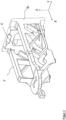
- figure 1 shows the exempted mainland F of the weighing block according to figure 9 in schematic side view.
- the mainland F is partially formed with a truss-like structure.
- a recess C is formed in the mainland F at the first block end B 1 , which recess is intended to receive sections of the links H and M .
- the mainland F has an approximately cuboid outer contour, with the interior being kept largely free.
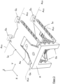
- figure 2 shows the mainland with the parallel links L o , L u arranged on it.
- the links have a truss-like structure made up of individual prisms running in the transverse direction Y.
- the top of the upper link L o and the underside of the lower link L u are largely closed, with both links in the longitudinal direction X on the side facing away from the first block end B 1 having a recess for receiving sections of the load receptor A.
- Via support joints Gs are the handlebars are articulated to the mainland F.
- the support joints are designed as cross spring joints.
- FIG figure 3 shows a schematic representation of the load receiver A. This is connected to the parallel links L o , L u via link joints G R , the support joints and the link joints forming pivot axes A GS and A GR , which in the embodiment according to FIG figure 3 all parallel to each other in the transverse direction Y and are not fully labeled. Also, the load receptor A shows sections with a truss-like structure for weight saving. A middle section A M of the load receiver A protrudes in the longitudinal direction X into the recess in the upper link L o .
- FIG 4 shows the partially broken load receptor A from diagonally below.
- a coupling element Kan engages with it.
- the coupling element has two load joints G L arranged one above the other in the vertical direction Z, which are each designed as cross spring joints and each have a pivot axis A GL running in the transverse direction Y.
- the upper load joint is connected to section A M of load receptor A and is used to receive and transfer a load introduced into load receptor A.
- Arranged between the two load joints of the coupling element K is a web connecting the two joints to one another.
- the lower load link sits in a pocket of a first lever H and engages a first end portion H of the lever H on this.
- the lever A extends in the longitudinal direction X to a second end region H 2 in order to be coupled to a second lever M there.
- figure 5 shows the arrangement of the first lever H with a second lever M extending through it.
- the second lever M also extends in the longitudinal direction X from a first end area M1 to a second end area M2 (see 6 ).
- the lever H is provided at its first end region H for support on the mainland (not shown) with two support joints Gs which are one behind the other in the transverse direction Y and which form a common pivot axis A GS .
- the lever H is approximately symmetrical about a central XZ plane, and the rear support joint Gs is in figure 5 hidden by sections of the lever construction.
- the two support joints Gs are designed as cross spring joints (all in the Figures 1 to 9
- the cruciform joints shown each comprise three webs which are arranged one behind the other in the direction of the pivot axis and which connect the two sections which are to be guided in an articulated manner with one another.
- the middle web is inclined by 90° relative to the pivot axis relative to the other two webs).
- the first lever H is penetrated by a free space which runs in the longitudinal direction X and is occupied by the second lever M.
- Both levers are at least partially designed as a framework construction.
- FIG 6 shows from another view how the first lever H is connected at its second end area H 2 via a coupling element K to the first end area M 2 of the second lever M.
- the coupling element K again comprises two load joints arranged one above the other in the height direction Z (of which only the lower one is labeled).
- the two load joints A GL form, analogously to the design of the coupling element in figure 4 , in each case a pivot axis A GL running in the transverse direction Y. Both load joints are connected to each other via an intermediate web. Unlike the coupling element K in figure 4 here the web is interspersed with recesses in order to save weight.
- the lower load joint G L is arranged in a pocket T of the handlebar M.
- the pocket T has two wall sections W which are parallel to one another and which accommodate the lower load hinge G L between them.
- the two wall sections W are connected to one another by a common support section V at their lower end.
- the lower load joint G L acts on this support section V in order to introduce the lever force passed from the first lever H through the coupling element K into the lever M.
- a support joint Gs is provided on the outer side of the two wall sections facing away from the lower load joint, which supports the lever M on the mainland (not shown). figure 6 only shows the front of the two joints).
- an upper support section V protrudes laterally outwards in the transverse direction Y on the outside of each wall section W facing away from the lower load joint G L , which is gripped on its underside by the webs of the support joint Gs designed as a cross spring joint.
- Each wall section W of the pocket T thus has, on opposite sides in the transverse direction Y, two support sections V that are offset from one another in the height direction Z, so that a cross section perpendicular to the longitudinal direction X through each wall section would result in an approximately Z-shaped contour (with sections orthogonal to one another).
- the two support joints Gs on the first end area M of the lever M determine the pivot axis about which the lever can be pivoted relative to the mainland.
- the distance between the common pivot axis A GS of the two supporting joints Gs lying one behind the other in the transverse direction Y and the distance between the pivot axis A GL of the lower load joint G L determines a short lever arm of the lever M. In order to achieve high transmission ratios, the distance should be as small as possible.
- the joints G L , Gs that determine the above-mentioned center distance have a certain extent transversely to their pivot axes (which is formed in particular by the webs of the flexure joint), the pivot axes can be formed very close to one another due to the offset arrangement of the respective joints in the transverse direction Y .
- the upper load joint G L of the coupling element K which is attached to the second end area H 2 of the lever H, protrudes through a recess so far into the lever H that the pivot axis A GL of the upper load joint runs through the upper lever H. This also results in an overall height that is reduced, in particular in height directions H.
- FIG 5 one of the support joints Gs provided on the first end region H1 of the lever H.
- figure 6 shows the second support joint Gs opposite this joint in the transverse direction Y (in figure 6 rightmost).
- a pocket T is also provided there, which extends with a wall section at least on one side of the support joint.
- a support section V protrudes outwards from this wall section in the transverse direction Y in order to be able to accommodate the upwardly protruding webs of the support joint Gs.
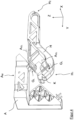
- figure 7 shows the arrangement according to figure 6 , embedded in the mainland F. It can be seen how the two levers M, H project into a recess of the mainland F in the region of their coupling by means of a coupling element K in order to be able to form maximum lever lengths. It can also be seen how the front support joint Gs of the lower lever M is supported on the mainland F.
- the mainland At its rear end in the X-direction, the mainland has a fastening section E 1 in order to arrange a component of the force compensation system thereon, in particular a permanent magnet D. In the X-direction there is another section E 2 which is used to hold the element Q 2 of the position detector Q is provided.
- figure 8 shows the construction according to figure 9 in a tilted view, but without the upper and lower links L o , L u .
- a coil P carried by the lower lever M via an extension bolted to it, which moves relative to a permanent magnet D carried by the mainland F as a function of the weight absorbed by the load receptor A and translated by the levers.
- Coil P and permanent magnet D form elements of an electromagnetic force compensation system, with which the pivoting movement of the lever M is compensated in order to be able to deduce the weight force to be measured from the coil current required for this.
- the coil P and the permanent magnet D are in the longitudinal direction X within an im Load receptor A provided recess arranged to form the shortest possible space in the longitudinal direction X maximum lever lengths or translations can.
- the individual components of the weighing block according to the invention can advantageously penetrate one another in order to thereby reduce installation space.
- penetration can take place in that a first component has a recess into which the other component protrudes.
- the components can also penetrate each other, which is based on figure 10 should be explained.
- Two components 1, 2, which extend in the longitudinal direction X, can be seen there in a cross-section formed transversely to the longitudinal direction X.
- component 1 has individual partial areas T 1
- the cross section of component 2 is made up of the respective partial areas T 2 .
- the cross section of component 1 is encircled by an envelope curve V 1
- the envelope curve V 2 encircles the cross section of component 2.
- the mutual penetration of the two components is characterized in that partial areas of one component are located within the envelope curve of the other component. This enables a stable and particularly space-saving arrangement of the components. Of course, more than two different components can penetrate each other in this way.
- figure 10 also makes it clear that the cross-sectional area composed of the individual partial areas of a component is significantly smaller than the area encircled by the respective envelope curve of this cross-section.
- a lever configured as a framework could have the cross section of component 1, with the individual partial surfaces T 1 corresponding to the sections through the rods, which vary in their dimensions.
- Component 2 could be another truss-lever coupled to the lever, with both levers in the in figure 10 exemplified manner can penetrate.
- figure 10 is only intended to illustrate the penetration principle of components arranged one inside the other, whose cross-sections and partial areas can also be different depending on the requirements.
- figure 11 shows an example of a link L o designed as a framework, which has two support joints Gs on the mainland (not shown) and two link joints G R is articulated to the load receptor, also not shown.
- the truss structure offers high rigidity in all spatial directions at a low weight.
- the material-free space between the bars offers space for other components that could penetrate the handlebars.
- one or more other components of the weighing block can of course also be designed like trusses based on this model.
- FIG. 12a shows an example of a truss-like structure of a component that is made up of individual prisms or is interspersed with prism-shaped recesses.
- An alternative design is in Figure 12b to see in which a cuboid block is interspersed with spherical recesses.
Description
Die vorliegende Erfindung betrifft einen monolithischen Wägeblock und ein Verfahren zu dessen Herstellung.The present invention relates to a monolithic weighing block and a method for its manufacture.
Monolithische Wägeblöcke ("Monoblock") für Wägezellen sind aus dem Stand der Technik bekannt. Sie umfassen einen oder mehrere Lenker und einstückig damit verbundene weitere Komponenten einer Hebelmechanik, beispielsweise Parallellenker, einen Lastaufnehmer und einen als Festland bezeichneten Abschnitt. "Festland" benennt dabei einen Bereich des Wägeblocks, der im Betrieb im Wesentlichen ortsfest bleibt und zur Ausbildung der Stützstellen bzw. Schwenkpunkte von Hebeln dient. Auch eine Komponente der elektromagnetischen Kraftkompensation (meist ein Permanentmagnet), oder ein Positionsdetektor, wird vom Festland getragen.Monolithic weighing blocks ("monoblock") for load cells are known from the prior art. They comprise one or more links and further components of a lever mechanism connected to them in one piece, for example parallel links, a load receiver and a section designated as the mainland. "Mainland" refers to an area of the weighing block that essentially remains stationary during operation and is used to form the support points or pivot points of levers. A component of the electromagnetic force compensation (usually a permanent magnet), or a position detector, is also carried by the land.
Die monolithische Bauart vermeidet unter anderem Wärmespannungen, und ein etwaiger Fertigungsaufwand durch den Zusammenbau einzelner Komponenten des Wägeblocks entfällt. Allerdings ist die Bearbeitung eines solchen Wägeblocks nicht beliebig möglich, da einzelne Komponenten in einer ersten Richtung hintereinanderliegen können und durch entsprechende Schnitte senkrecht zu dieser Richtung voneinander getrennt werden müssen (Hinterschneidungen). Die Entfernung von Material aus dem Monoblock kann daher nur dort bzw. nur aus einer solchen Richtung erfolgen, in der eine andere Komponente den Zugang des Werkzeugs nicht behindert. Außerdem verleiht das nicht entfernte, funktionell jedoch überflüssige Material dem Monoblock unnötiges Gewicht, und die Herstellung von Hinterschneidungen ist aufwendig.Among other things, the monolithic design avoids thermal stresses, and there is no production work involved in assembling individual components of the weighing block. However, the processing of such a weighing block is not arbitrarily possible, since individual components can lie one behind the other in a first direction and have to be separated from one another by appropriate cuts perpendicular to this direction (undercuts). The removal of material from the monobloc can therefore only take place there or only from such a direction in which another component does not impede the access of the tool. In addition, the material that has not been removed, but is functionally superfluous, gives the monobloc unnecessary weight, and the production of undercuts is expensive.
Die Fertigung der Monoblockstruktur ist im Stand der Technik begrenzt auf die Bearbeitung eines dreidimensionalen Körpers, dem gezielt Material entnommen wird, etwa durch Fräsen, Erodieren oder Bohren. Die verbleibenden Materialbereiche bilden einzelne, miteinander verbundene Elemente des Monoblocks aus. Da die Materialentnahme nicht an beliebigen Positionen innerhalb des Monoblocks möglich ist, sind auch die Gestaltungsspielräume zur Ausbildung der einzelnen Elemente, insbesondere zur Erzielung der nötigen Steifigkeit bei möglichst geringem Gewicht, begrenzt.In the prior art, the manufacture of the monoblock structure is limited to the processing of a three-dimensional body from which material is specifically removed, for example by milling, eroding or drilling. The remaining material areas form individual, interconnected elements of the monoblock. Since the removal of material is not possible at random positions within the monoblock, the scope for designing the individual elements, in particular for achieving the necessary rigidity with the lowest possible weight, is also limited.
Aus der
Die
In der
Die Aufgabe wird gelöst durch einen Wägeblock nach Ansprüchen 1-6 und 8-10 und einem Verfahren nach Anspruch 12.The object is achieved by a weighing block according to claims 1-6 and 8-10 and a method according to claim 12.
Die Erfindung beruht auf der Erkenntnis, einen Monoblock mit besonders geringem Gewicht herstellen zu können nach dem Prinzip der generativen Fertigung, auch bekannt als 3-D Druck. Dabei werden in einer Richtung, beispielsweise einer Längsrichtung X, nacheinander dünne Materialschichten aufeinander gelegt und miteinander verbunden, um so nach und nach einen räumlichen Körper auszubilden. Anders als im bisher bekannten Stand der Technik, bei dem Monoblöcke durch Materialentnahme aus einem Vollmaterial hergestellt werden, wird hier der Monoblock mit seinen Komponenten durch Materialzufügung schichtweise aufgebaut. In Versuchen konnte die Anmelderin überraschend feststellen, dass die hohen Anforderungen an die Maßgenauigkeit bei der Herstellung von Monoblöcken, die im Bereich von Mikrometern liegt, auch bei durch 3-D Druck hergestellten Monoblöcken erreicht werden kann. Gerade für die Ausbildung von Dünnstellen bzw. Gelenken, die bei herkömmlichen Monoblöcken oft durch eng nebeneinander liegende parallele Bohrungen erzeugt werden, konnte das Vorurteil geringer Fertigungsgenauigkeit im 3-D Druck widerlegt werden. Die Nutzung des 3-D Drucks in der speziellen Anwendung für Monoblöcke bietet mehrere signifikante Vorteile:
- Bei den bekannten Monoblöcken lässt sich funktionell überflüssiges Material nur bedingt entfernen, da bestimmte Komponenten des Wägeblocks den Zugang der Werkzeuge erschweren bzw. verhindern. Entsprechend sind die Wägeblöcke schwerer als nötig. Dickere Materialbereiche wärmen sich bei Änderung der Umgebungstemperatur außerdem langsamer auf oder kühlen langsamer ab als dünnere Materialbereiche, sodass unnötig Zeit vergeht, bis stationäre Betriebsbedingungen erreicht sind. Ein erfindungsgemäß hergestellter Monoblock weist nur dort Material auf, wo es funktionell erforderlich ist, sodass das Gesamtgewicht auf ein Minimum reduziert wird. Die Ausbildung der einzelnen Komponenten des Monoblocks als Stabwerk oder jedenfalls mit möglichst kleinen Einzelquerschnitten reduziert außerdem die Empfindlichkeit bei Temperaturänderungen.
- Bisher war es nötig, den Rohblock mit Werkzeugen (insbesondere Fräswerkzeugen) von unterschiedlichen Seiten her zu bearbeiten, um Material entnehmen und insbesondere die einzelnen Komponenten innerhalb des Wägeblocks aus dem Vollen heraus fräsen zu können. Diese aufwändige Bearbeitung kann erfindungsgemäß entfallen.
- Häufig lassen sich komplexere Wägeblöcke (beispielsweise mit mehr als einem Hebel) nicht ohne Hinterschneidungen im Block herstellen. Dazu muss Material im Blockinneren in einer ersten und anschließend einer dazu senkrechten zweiten Richtung entfernt werden. Um in beiden Fällen mit dem Werkzeug die Bearbeitungsposition erreichen zu können sind häufig Bearbeitungsöffnungen in anderen Komponenten des Wägeblocks, insbesondere den Parallellenkern, erforderlich, die deren Festigkeit schwächen. Im 3-D Druck dagegen können die Hinterschneidungen gebildet werden durch Zonen, in denen keine Materialschicht aufgebaut wird. Die Werkzeugzuführung zur Materialentnahme ist hier nicht nötig.
- Aufgrund der hohen Fertigungspräzision lassen sich die einzelnen Komponenten des Monoblocks mittels 3-D Druck sehr eng aneinander liegend ausbilden, so dass die Zwischenräume kleiner ausfallen können als dies mit herkömmlichen Werkzeugen überhaupt herstellbar wäre. Zwar ist zur Herstellung dünner Schnitte in Monoblöcken auch das Erodieren bekannt, hierfür müssen die Schnitte jedoch durch den ganzen Block geführt werden, was die Konstruktionsfreiheit erheblich einschränkt.
- Die einzelnen Komponenten des Wägeblock lassen sich so herstellen, dass sie einander durchdringen bzw. einen Teil des Wägeblockvolumens gemeinsam ausnutzen. Das ist insbesondere möglich durch Ausbildung der Komponenten mit Ausnehmungen oder als Stabwerke, wobei Abschnitte des einen Stabwerks innerhalb von Abschnitten des anderen Stabwerks erstellt werden können. Diese Technik, bei der eine Vielzahl von Hinterschneidungen entsteht, ist im Stand der Technik für Monoblöcke nicht bekannt.
- In the case of the known monoblocks, functionally superfluous material can only be removed to a limited extent, since certain components of the weighing block make it difficult or prevent access for the tools. Accordingly, the weighing blocks are heavier than necessary. Also, thicker areas of material heat up or cool down more slowly than thinner areas of material as the ambient temperature changes, thereby adding unnecessary time to steady-state operating conditions. A monobloc manufactured according to the invention only has material where it is functionally required, so that the overall weight is reduced to a minimum. The design of the individual components of the monoblock as a framework or at least with the smallest possible individual cross-sections also reduces the sensitivity to temperature changes.
- Previously it was necessary to process the raw block with tools (in particular milling tools) from different sides in order to remove material and in particular to be able to mill the individual components within the weighing block from the solid. This complex processing can be omitted according to the invention.
- More complex weighing blocks (e.g. with more than one lever) often cannot be manufactured without undercuts in the block. For this purpose, material inside the block must be removed in a first direction and then in a second direction perpendicular thereto. In order to be able to reach the machining position with the tool in both cases, machining openings are often required in other components of the weighing block, in particular the parallel links, which weaken their strength. In 3D printing, on the other hand, the undercuts can be formed by zones in which there is no layer of material is built up. The tool feed for material removal is not necessary here.
- Due to the high manufacturing precision, the individual components of the monoblock can be formed very closely together using 3D printing, so that the gaps can be smaller than could be produced with conventional tools. Erosion is also known for producing thin cuts in monoblocks, but for this purpose the cuts must be made through the entire block, which considerably limits the design freedom.
- The individual components of the weighing block can be manufactured in such a way that they penetrate each other or use part of the weighing block volume together. This is possible in particular by designing the components with recesses or as trusses, with sections of one truss being able to be created within sections of the other truss. This technique, in which a large number of undercuts are produced, is not known in the prior art for monoblocks.
Ein erfindungsgemäßer Wägeblock erstreckt sich in einer Längsrichtung X, einer dazu orthogonalen Querrichtung Y und einer zu diesen beiden Richtungen wiederum orthogonalen Höhenrichtung Z. Der Wägeblock umfasst an einem ersten Blockende einen Festlandabschnitt, der insbesondere zur Abstützung von Lenkern oder Hebeln vorgesehen ist. Auch Teile eines Kraftkompensationssystems können am Festland befestigt sein. Außerdem weist der Wägeblock zwei Lenker auf, die sich in Längsrichtung X erstrecken und jeweils mit ihrem ersten Ende über ein Stützgelenk mit dem Festland verbunden sind. An ihrem dem ersten Ende gegenüberliegenden zweiten Ende greifen die beiden Lenker an einem gemeinsamen Lastaufnehmer an, der mittels der Lenker in Höhenrichtung Z relativ zum Festland parallel geführt wird. Der Lastaufnehmer dient zur Aufnahme einer in Höhenrichtung Z eingeleiteten Gewichtskraft. Ein solches System, welches in einer einfachsten Form ohne kraftübersetzende Hebel auskommt, wird als direkt tragendes System bezeichnet, wobei die durch eine Gewichtskraft verursachte Bewegung des Lastaufnehmers kompensiert wird durch eine Gegenkraft, die über ein Kraftkompensationssystem erzeugt wird. Beispielsweise eine Spule als Teil dieses Kraftkompensationssystems kann dann unmittelbar am Lastaufnehmer angeordnet sein.A weighing block according to the invention extends in a longitudinal direction X, a transverse direction Y orthogonal thereto and a vertical direction Z orthogonal to these two directions. Parts of a force compensation system can also be attached to the mainland. In addition, the weighing block has two links which extend in the longitudinal direction X and are each connected to the mainland at their first end via a support joint. At their second end opposite the first end, the two links act on a common load receiver, which is guided parallel to the mainland by means of the links in the vertical direction Z. The load receptor is used to absorb a weight force introduced in the height direction Z. Such a system, which in its simplest form manages without force-translating levers, is referred to as a directly supporting system, whereby the movement of the load receptor caused by a weight force is compensated by an opposing force that is generated via a force compensation system. For example a coil as part of this Force compensation system can then be arranged directly on the load receptor.
Bereits ein solches System ohne Hebel gestattet im 3-D Druck die Ausbildung seiner Komponenten mit möglichst geringem Gewicht. Außerdem könnte beispielsweise das Festland, welches zur Aufnahme des zum Kraftkompensationssystem gehörenden Magneten bis in den Bereich der Spule am Lastaufnehmer ausgebildet sein muss, die Lenker durchdringen. Festland und Lenker können so teilweise ineinanderliegend ausgebildet werden, wobei einzelne Stäbe, Streben oder sonstige Materialbereiche des Lenkers nur minimalen Abstand zu denjenigen des Festlandes aufweisen müssen.Even such a system without a lever allows its components to be designed with the lowest possible weight in 3D printing. In addition, for example, the mainland, which must be designed to accommodate the magnet belonging to the force compensation system up to the area of the coil on the load receptor, could penetrate the link. The mainland and link can thus be designed to lie partially one inside the other, with individual rods, struts or other material areas of the link only having to have a minimal distance to those of the mainland.
Eine bevorzugte Ausführungsform des Wägeblocks umfasst wenigstens einen ersten Hebel, der sich (vorzugsweise in Längsrichtung X) zwischen einem ersten Endbereich und einem zweiten Endbereich erstreckt (diese Erstreckungsrichtung, entlang derer der Hebel Hebelarme zur Veränderung von Kräften ausbildet, kann auch als Haupterstreckungsrichtung bezeichnet werden). Am ersten Endbereich ist der Hebel über ein Koppelelement mit dem Lastaufnehmer verbunden, um die Weiterleitung einer Kraft vom Lastaufnehmer in den Hebel zu gewährleisten. Das Koppelelement umfasst wenigstens ein Lastgelenk, sodass ein Abschnitt des Koppelelements relativ zum Hebel oder zum Lastaufnehmer um eine durch das Lastgelenk gebildete Schwenkachse schwenkbar ist. Ebenfalls am ersten Endbereich ist der erste Hebel außerdem über ein Stützgelenk mit dem Festland verbunden, wobei auch das Stützgelenk eine Schwenkachse ausbildet. Die Ausführung mit wenigstens einem Hebel lässt sich besonders gut mittels 3-D Druck herstellen, da sich hier die vorgenannten Vorteile voll auswirken.A preferred embodiment of the weighing block comprises at least one first lever, which extends (preferably in the longitudinal direction X) between a first end area and a second end area (this direction of extension, along which the lever forms lever arms for changing forces, can also be referred to as the main direction of extension) . At the first end area, the lever is connected to the load receiver via a coupling element in order to ensure that a force is transmitted from the load receiver to the lever. The coupling element comprises at least one load joint, so that a section of the coupling element can be pivoted about a pivot axis formed by the load joint relative to the lever or to the load receiver. Also in the first end area, the first lever is also connected to the mainland via a support joint, the support joint also forming a pivot axis. The embodiment with at least one lever can be produced particularly well by means of 3D printing, since the aforementioned advantages have a full impact here.
Der Begriff "Stützgelenk" bezeichnet im weiteren Gelenke, die ein bewegliches Teil des Monoblocks, insbesondere einen Hebel oder einen Lenker, mit dem Festland verbinden bzw. daran abstützen. Als "Lenkergelenk" sollen diejenigen Gelenke bezeichnet werden, über die die Lenker mit dem Lastaufnehmer verbunden sind. Über ein "Lastgelenk" werden zwei bewegliche Abschnitte des Wägeblocks miteinander verbunden. Insbesondere wird der Lastaufnehmer über ein oder mehrere Lastgelenke mit einem Ende eines Hebels verbunden, und auch die Verbindung von Hebeln untereinander erfolgt über Lastgelenke. Ein Lastgelenk ist in der Regel Teil eines Koppelelements.The term “support joint” further refers to joints that connect a movable part of the monobloc, in particular a lever or a link, to the mainland or support it. Those joints are to be referred to as “link joints” via which the links are connected to the load receptor. Two movable sections of the weighing block are connected to one another via a "load joint". In particular, the load receiver is connected to one end of a lever via one or more load links, and levers are also connected to one another via load links. A load joint is usually part of a coupling element.
Alle diese Gelenke bilden jeweils eine Schwenkachse aus, um die die beiden über das Gelenk miteinander verbundenen Abschnitte relativ zueinander schwenkbar sind.All of these joints each form a pivot axis about which the two sections connected to one another via the joint can be pivoted relative to one another.
Eine besonders bevorzugte Ausführungsform der Erfindung sieht vor, dass ein Lastgelenk als Kreuzfedergelenk ausgebildet ist. Dabei werden die beiden gelenkig miteinander zu verbindenden Abschnitte über wenigstens zwei Materialstege miteinander verbunden, die einander im Bereich der Schwenkachse vorzugsweise nicht berühren und wobei einer der Materialstege in einer Projektion entlang der Schwenkachse einen Winkel (α :# 0°) mit dem anderen Materialsteg bildet. Anders als bei sogenannten Dünnstellengelenken wird hier die Schwenkachse erzeugt durch zwei in Achsenrichtung hintereinanderliegende, einander kreuzende Materialstege. Vorzugsweise liegt der Kreuzungswinkel im Bereich 45° < α < 135° höchst vorzugsweise bei genau 90°.A particularly preferred embodiment of the invention provides that a load joint is designed as a cross spring joint. The two sections to be connected to one another in an articulated manner are connected to one another via at least two material webs which preferably do not touch one another in the region of the pivot axis and one of the material webs forming an angle (α : # 0°) with the other material web in a projection along the pivot axis . In contrast to so-called thin-point joints, the pivot axis is generated here by two material webs lying one behind the other in the axial direction and crossing one another. The crossing angle is preferably in the range 45°<α<135°, most preferably exactly 90°.
Aufgrund der in Achsrichtung hintereinander liegenden Materialstege sind Kreuzfedergelenke nicht ohne Hinterschneidungen in Richtung ihrer Schwenkachse herstellbar. Zugleich haben die gekreuzten Materialstege eine horizontale bzw. vertikale Ausdehnung quer zur Schwenkachse, das Gelenk nimmt also quer zur Schwenkachse einen gewissen Raum ein. Ein Lastgelenk, über welches eine Kraft an einem Hebelendbereich in den Hebel eingeleitet wird, ist zweckmäßigerweise in Längsrichtung des Hebels sehr nahe bei einem den Hebel abstützendes Stützgelenk angeordnet, um dadurch einen kurzen Hebelarm bzw. eine ausreichend hohe Hebelübersetzung erzielen zu können, und die Schwenkachse beider Gelenke verlaufen dabei parallel . Die Ausbildung des Lastgelenks als Kreuzfedergelenk steht jedoch der Ausbildung des eng benachbarten Stützgelenks im Wege, solange die beiden Gelenke auf herkömmliche Weise, nämlich durch Materialentnahme aus einem monolithischen Block hergestellt werden. Gelenke werden dort nämlich meist durch Bohrungen in Schwenkachsenrichtung ausgebildet, deren Durchmesser den Mindestabstand zu einem benachbarten weiteren Gelenk bestimmen. Ein auf diese Weise erzeugtes Kreuzfedergelenk könnte nur dann in geringerem Achsabstand zu einem weiteren Gelenk ausgebildet werden, wenn die beiden Gelenke in Achsrichtung versetzt zueinander hintereinander lägen. Dann aber durchdringen die Bohrungen des einen Gelenks den Bauraum des anderen Gelenks, was nur durch aufwendige Hinterschneidungen verhindert werden könnte. Der generative Aufbau des erfindungsgemäßen Wägeblocks gestattet hingegen die Ausbildung von Stützgelenk und Lastgelenk in geringem Abstand zueinander, während zugleich die Vorteile des Kreuzfedergelenks für das Lastgelenk nutzbar sind. Besonders vorteilhaft wirkt sich dies aus, wenn auch das am gleichen Hebel-Endbereich wie das Lastgelenk vorgesehene Stützgelenk des Hebels als Kreuzfedergelenk der vorgenannten Art ausgebildet wird. Beide Gelenke liegen dabei mit Blick entlang ihrer (parallel zueinander verlaufenden) Schwenkachsen hintereinander, und ihre Ausdehnung quer zur jeweiligen Schwenkachse ist dann größer als der die Länge des Hebelarms definierende Abstand der Schwenkachsen. Mit herkömmlichen Fertigungsverfahren ist eine solche Anordnung aufgrund der Hinterschneidungen und der für die Bearbeitung erforderlichen materialfreien Bereiche rund um die Gelenke zumindest wirtschaftlich, und wohl auch technisch nicht machbar. Im 3-D Druck hingegen können die Gelenke in der genannten Weise ausgebildet und positioniert sein, ohne dass komplizierte Bearbeitungsvorgänge dafür nötig wären.Due to the material webs lying one behind the other in the axial direction, flexure joints cannot be produced without undercuts in the direction of their pivot axis. At the same time, the crossed webs of material have a horizontal or vertical extent transverse to the pivot axis, so the joint occupies a certain space transverse to the pivot axis. A load joint, via which a force is introduced into the lever at a lever end region, is expediently arranged in the longitudinal direction of the lever very close to a support joint supporting the lever, in order to be able to achieve a short lever arm or a sufficiently high leverage ratio, and the pivot axis both joints run parallel. The design of the load joint as a cross spring joint, however, stands in the way of the design of the closely adjacent support joint as long as the two joints are produced in the conventional manner, namely by removing material from a monolithic block. Joints are usually formed there by boreholes in the direction of the pivot axis, the diameter of which determines the minimum distance from an adjacent further joint. A cross spring joint produced in this way could only be formed at a smaller center distance to another joint if the two joints were offset one behind the other in the axial direction. But then the bores of one joint penetrate the installation space of the other joint, which could only be prevented by complex undercuts. The generative structure of the weighing block according to the invention, however, allows the formation of support joint and load joint at a small distance from each other, while at the same time the advantages of the cross spring joint can be used for the load joint. This has a particularly advantageous effect if the support joint of the lever provided on the same end region of the lever as the load joint is designed as a cross spring joint of the aforementioned type. Viewed along their pivot axes (running parallel to one another), both joints lie one behind the other, and their extension transversely to the respective pivot axis is then greater than the distance between the pivot axes that defines the length of the lever arm. With conventional manufacturing methods, such an arrangement is at least economically, and probably also technically, not feasible due to the undercuts and the material-free areas around the joints required for machining. In 3D printing, on the other hand, the joints can be designed and positioned in the manner mentioned, without complicated machining processes being necessary for this.
Ein Koppelelement, welches zur Kraftübertragung zwischen zwei Hebeln oder einem Hebel und dem Lastaufnehmer dient, umfasst nach einer vorteilhaften Ausführungsform der Erfindung wenigstens ein, vorzugsweise zwei Kreuzfedergelenke der vorgenannten Art, die durch einen die Hebelkraft weiterleitenden Materialsteg zueinander beabstandet sind. Je nach Ausdehnung der jeweiligen Gelenke quer zu ihrer Schwenkachse können die Gelenke, mit Blick entlang ihrer parallelen Schwenkachsen, versetzt hintereinander oder seitlich nebeneinander/übereinander angeordnet sein. Auch an einem Koppelelement erlaubt der 3-D Druck die Anordnung eines oder zweier Kreuzfedergelenke (mit ihren zugehörigen Hinterschneidungen) in engem Abstand zueinander, wobei die Ausbildung eines Koppelelements mit wenigstens einem Kreuzfedergelenk auch unabhängig davon den Vorteil bringt, eine Schwenkachse anders als über eine Dünnstelle zu definieren und diese besondere Bauart gerade an einem Lastgelenk vorzusehen. (Diese erfindungsgemäße Ausbildung eines Koppelelements ist nicht notwendigerweise gekoppelt an einen erfindungsgemäßen Wägeblock und bietet auch unabhängig davon die genannten, vorzugsweise auch separat schutzfähigen Vorteile.)According to an advantageous embodiment of the invention, a coupling element, which serves to transmit force between two levers or a lever and the load receiver, comprises at least one, preferably two, flexural joints of the aforementioned type, which are spaced apart from one another by a material web that transfers the lever force. Depending on the extent of the respective joints transversely to their pivot axis, the joints can be arranged offset one behind the other or side by side/on top of one another, viewed along their parallel pivot axes. 3D printing also allows the arrangement of one or two flexure joints (with their associated undercuts) at a close distance from one another on a coupling element, with the formation of a coupling element with at least one flexure joint also independently of this bringing the advantage of a pivot axis other than via a thin spot to define and to provide this special design on a load joint. (This design of a coupling element according to the invention is not necessarily coupled to a weighing block according to the invention and also offers the advantages mentioned, preferably also separately protectable, independently of this.)
Eine weitere vorteilhafte Ausführungsform der Erfindung sieht vor, dass die Schwenkachsen der an den Lenkern angeordneten Stützgelenke bzw. Lenkergelenke auf den Eckpunkten eines Parallelogrammes liegen. Die Lenker liegen dann in Form eines oberen und eines unteren Lenkers in Z-Richtung übereinander und erstrecken sich orthogonal dazu in Längsrichtung X zwischen dem Lastaufnehmer und dem Festland (andere räumliche Anordnungen sind ebenfalls denkbar). Diese Anordnung ermöglicht in vorteilhafter Weise, das Festland zwischen die Lenker zu erstrecken, um so weitere Stützstellen ausbilden zu können.A further advantageous embodiment of the invention provides that the pivot axes of the support joints or link joints arranged on the links lie on the corner points of a parallelogram. The links then lie one above the other in the form of an upper and a lower link in the Z direction and extend orthogonally in addition in the longitudinal direction X between the load receptor and the mainland (other spatial arrangements are also conceivable). This arrangement makes it possible in an advantageous manner to extend the mainland between the links in order to be able to form further support points.
Eine weitere vorteilhafte Ausführungsform der Erfindung sieht vor, dass wenigstens ein mit einem Hebel verbundenes Lastgelenk oder Stützgelenk, in Richtung seiner Schwenkachse gesehen, auf einer, vorzugsweise auf beiden Seiten von einem Materialabschnitt dieses Hebel eingefasst ist. Der Hebel erstreckt sich dann auch seitlich des Gelenks (beispielsweise in Querrichtung Y gesehen) und kann dort eine für seine gewünschte Steifigkeit ausreichende Z-Abmessung aufweisen. Diese Anordnung eines Gelenks seitlich zu dem mit dem Gelenk verbundenen Hebel bietet konstruktive Vorteile. Die beiden durch das Gelenk miteinander zu verbindenden Elemente des Wägeblocks können in Richtung der Schwenkachse zumindest teilweise oder auch vollständig hintereinander angeordnet werden, sodass in diesem Bereich die Gesamtbauhöhe der beiden Elemente mit dem dazwischenliegenden Gelenk geringer ausfällt als die Summe der Bauhöhen der einzelnen Elemente und des Gelenks. Ein beispielsweise um eine Y-Achse zu schwenkender Hebel kann über ein Stützgelenk am Festland abgestützt werden, welches sich in Y-Richtung im Wesentlichen vor bzw. hinter diesem Hebel befindet. Im Stand der Technik verläuft der Hebel stets in X- oder Z-Richtung beabstandet an der Schwenkachse vorbei, da für die erfindungsgemäße Ausbildung (vorzugsweise schmale) Hinterschneidungen erforderlich wären, die in zerspanender Fertigung quasi nicht herstellbar sind.A further advantageous embodiment of the invention provides that at least one load joint or support joint connected to a lever, viewed in the direction of its pivot axis, is bordered on one side, preferably on both sides, by a material section of this lever. The lever then also extends to the side of the joint (seen, for example, in the transverse direction Y) and can have a Z dimension there that is sufficient for its desired rigidity. This arrangement of a joint at the side of the lever connected to the joint offers design advantages. The two elements of the weighing block to be connected to each other by the joint can be arranged at least partially or completely one behind the other in the direction of the pivot axis, so that in this area the total height of the two elements with the joint in between is less than the sum of the heights of the individual elements and the joint. A lever to be pivoted about a Y-axis, for example, can be supported on the mainland via a support joint, which is located essentially in front of or behind this lever in the Y-direction. In the prior art, the lever always runs in the X or Z direction at a distance past the pivot axis, since (preferably narrow) undercuts would be required for the design according to the invention, which are virtually impossible to produce by machining.
Eine weitere vorteilhafte Ausführungsform der Erfindung sieht vor, dass wenigstens zwei am selben Hebel angreifende Gelenke in Richtung ihrer zueinander beabstandeten Schwenkachsen so hintereinander liegen, dass sich die senkrecht zu ihren Schwenkachsen gebildeten Gelenk-Querschnitte in einer Projektion in Schwenkachsenrichtung überdecken. Der zuvor bereits für das Lastgelenk mit benachbartem Stützgelenk beschriebene Vorteil bei Verwendung eines Kreuzfedergelenks lässt sich bei erfindungsgemäßem 3-D Druck auch auf andere Gelenkformen übertragen, die quer zu ihrer Schwenkachse eine gewisse seitliche Ausdehnung aufweisen. Dadurch wird es möglich, den in einer Richtung (X, Y, Z) bestehenden Schwenkachsenabstand zweier mit demselben Hebel verbundenen Gelenke, deren Schwenkachsen nicht fluchten, kleiner zu wählen als die Ausdehnung wenigstens eines der Gelenke in dieser Richtung, sodass die gelenkige Anbindung von Hebeln auf engem Raum möglich ist. Betroffen sind hier typischerweise Kombinationen von Gelenken verschiedener Art, also etwa ein Stützgelenk mit einem Lastgelenk, oder ein Lastgelenk mit einem Lenkergelenk. Dann gilt in der Regel, dass die jeweiligen Schwenkachsen zueinander beabstandet sind, also nicht fluchten.A further advantageous embodiment of the invention provides that at least two joints acting on the same lever are arranged one behind the other in the direction of their mutually spaced pivot axes in such a way that the joint cross-sections formed perpendicularly to their pivot axes overlap in a projection in the direction of the pivot axes. The advantage already described above for the load joint with an adjacent support joint when using a cross spring joint can also be transferred to other joint shapes with 3D printing according to the invention, which have a certain lateral extent transverse to their pivot axis. This makes it possible to reduce the pivot axis distance in one direction (X, Y, Z) between two joints connected to the same lever and whose pivot axes are not aligned. to be chosen smaller than the expansion of at least one of the joints in this direction, so that the articulated connection of levers is possible in a confined space. Combinations of different types of joints are typically affected here, for example a support joint with a load joint, or a load joint with a link joint. It is then generally the case that the respective pivot axes are spaced apart from one another, that is to say they are not aligned.
Der Umstand, dass sich die Schwenkachse eines Gelenks erfindungsgemäß auch durch das von diesem Gelenk geführte Element hindurch bewegen kann, erlaubt eine weitere vorteilhafte Ausführungsform, wonach wenigstens ein Hebel eine Tasche aufweist zur Aufnahme eines mit diesem Hebel verbundenen Gelenks. Die Tasche fasst das Gelenk somit wenigstens auf einer Seite ein und schützt es vor ungewollter Beaufschlagung oder Verschmutzung. Die Anordnung einer von einem Hebel gebildeten Tasche mit einem darin liegenden, den Hebel schwenkbar verbindenden Gelenk in monolithischer Ausführung ist mit herkömmlichen Zerspanungsverfahren kaum herstellbar.The fact that the pivot axis of a joint according to the invention can also move through the element guided by this joint allows a further advantageous embodiment, according to which at least one lever has a pocket for receiving a joint connected to this lever. The pocket thus encloses the joint at least on one side and protects it from unwanted impact or dirt. The arrangement of a pocket formed by a lever with a monolithic joint connecting the lever pivotally therein can hardly be produced with conventional machining processes.
Neben der platzsparenden Anordnung des Gelenks relativ zum Hebel (wieder kann die Schwenkachse durch den Hebel hindurch führen) können die Elemente der Tasche mehrere Funktionen übernehmen. Die Tasche umfasst dabei wenigstens einen Wandabschnitt, von dem auf einer Seite ein erster Stützabschnitt abragt zur Verbindung mit dem Gelenk, beispielsweise indem dort zwei gekreuzte Stege eines Kreuzfedergelenks angreifen. Auf der anderen Seite des Wandabschnitts kann ein weiterer Stützabschnitt abragen, um Elemente eines weiteren Gelenks anzubinden. Denkbar ist beispielsweise der Fall, dass, in Querrichtung Y gesehen, auf einer Seite einer Taschenwand eines Hebels ein Stützgelenk ausgebildet ist, welches den Hebel am Festland abstützt. Die Taschenwand erstreckt sich dann etwa entlang einer X-Z-Ebene. Das Stützgelenk greift hebelseitig (beispielsweise von unten) an dem Stützabschnitt an, der von einem oberen Bereich der Taschenwand in Querrichtung Y seitlich abragt. Das Gelenk erstreckt sich dabei im Wesentlichen seitlich neben bzw. entlang der Taschenwand und seine Schwenkachse verläuft in Querrichtung Y.In addition to the space-saving arrangement of the joint relative to the lever (again, the pivot axis can pass through the lever), the elements of the pocket can take on several functions. The pocket comprises at least one wall section from which a first support section protrudes on one side for connection to the joint, for example in that two crossed webs of a flexural joint engage there. A further support section can protrude on the other side of the wall section in order to connect elements of a further joint. It is conceivable, for example, that, viewed in the transverse direction Y, a support joint is formed on one side of a pocket wall of a lever, which supports the lever on the mainland. The pocket wall then extends approximately along an X-Z plane. The support joint acts on the lever side (for example from below) on the support section, which protrudes laterally in the transverse direction Y from an upper area of the pocket wall. The joint extends essentially laterally next to or along the pocket wall and its pivot axis runs in the transverse direction Y.
Auf der anderen Seite der Taschenwand, dem ersten Stützabschnitt diametral gegenüberliegend, ragt von einem unteren Bereich der Wand ein weiterer Stützabschnitt in Querrichtung Y (entgegengesetzt zum Stützabschnitt auf der anderen Seite) ab, der den unteren Angriffspunkt eines Koppelelements bilden soll. Das Koppelelement weist dazu ein mit dem weiteren Stützabschnitt zu verbindendes Lastgelenk aus, welches sich, ausgehend von diesem Stützabschnitt, entlang der diesseitigen Taschenwand aufwärts erstreckt und dessen Schwenkachse wiederum in Querrichtung Y verläuft. Auf beiden Seiten der Taschenwand ist dann jeweils ein Gelenk angeordnet, welches jeweils an einem zu verschiedenen Seiten der Taschenwand abragenden Stützabschnitts angreift. Die beiden Stützabschnitte bilden mit der Taschenwand so einen etwa "Z"-förmigen Querschnitt mit orthogonal zueinander verlaufenden Abschnitten.On the other side of the pocket wall, diametrically opposite the first support section, another support section protrudes from a lower area of the wall Transverse direction Y (opposite to the support section on the other side) from which is intended to form the lower point of application of a coupling element. For this purpose, the coupling element has a load joint which is to be connected to the further support section and which, starting from this support section, extends upwards along the pocket wall on this side and whose pivot axis in turn runs in the transverse direction Y. A joint is then arranged on both sides of the pocket wall, which articulation acts on a support section projecting on different sides of the pocket wall. The two support sections thus form an approximately "Z"-shaped cross-section with the pocket wall, with sections running orthogonally to one another.
Die Schwenkachsen der beiden Gelenke können auf diese Weise sehr nah beieinander liegen, um eine sehr große Hebelübersetzung zu erzeugen und gleichzeitig kann der Hebel, beispielsweise durch die Höhe der Taschenwand, eine hohe Biegesteifigkeit gegen Biegemomente um die Y-Achse ausbilden. Die beiden Gelenke liegen, in Y-Richtung gesehen, vor und hinter der Taschenwand, vorzugsweise unter geringem Y-Abstand zur Taschenwand, und die jeweilige seitliche Ausdehnung jedes Gelenks quer zu seiner Schwenkachse kann die Ausbildung des jeweils anderen Gelenks, anders als mit den bekannten zerspanenden Verfahren im Stand der Technik, nicht einschränken.In this way, the pivot axes of the two joints can be very close to one another in order to generate a very high lever ratio, and at the same time the lever can develop high flexural rigidity against bending moments around the Y-axis, for example due to the height of the pocket wall. The two joints are seen in the Y-direction, in front of and behind the pocket wall, preferably at a small Y-distance to the pocket wall, and the respective lateral extension of each joint transversely to its pivot axis can the formation of the other joint, differently than with the known cutting methods in the prior art, do not limit.
Nach einer weiteren vorteilhaften Ausführungsform der Erfindung ist wenigstens ein weiterer Hebel vorgesehen, der im Wesentlichen den gleichen Zweck hat wie der erste Hebel, um durch Hintereinanderschaltung beider Hebel ein noch höheres Übersetzungsverhältnis für die über den Lastaufnehmer eingeleitete Gewichtskraft zu erzielen, als dies mit nur einem Hebel möglich ist. Auch mehr als zwei Hebel können zu diesem Zweck hintereinander geschaltet werden, wobei ein mittig abgestützter Hebel die Kraft auch in unverändertem Betrag weiterleiten kann.According to a further advantageous embodiment of the invention, at least one further lever is provided, which essentially has the same purpose as the first lever, in order to achieve an even higher transmission ratio for the weight force introduced via the load receptor by connecting both levers in series than with just one leverage is possible. More than two levers can also be connected in series for this purpose, with a lever supported in the middle being able to transmit the force in an unchanged amount.
Der weitere Hebel erstreckt sich zwischen einem ersten Endbereich und einem zweiten Endbereich, wobei die Erstreckungsrichtung der Längsrichtung X bzw. der Erstreckungsrichtung des ersten Hebels entsprechen kann. Die erfindungsgemäße Ausbildung des Monoblocks im 3-D-Druck erlaubt es jedoch, die Erstreckungsrichtungen mehrerer miteinander gekoppelter Hebel unterschiedlich zu wählen. So könnte ein erster Hebel sich in Längsrichtung X erstrecken, während ein damit gekoppelter weiterer Hebel sich dazu schräg oder orthogonal erstreckt, beispielsweise in Querrichtung Y oder Höhenrichtung Z. Die die Hebel miteinander verbindenden Koppelelemente weisen dann zwei Gelenke auf, deren Schwenkachse nicht mehr parallel verlaufen. Mehrere hintereinander geschaltete Hebel können sich daher ebenso wie die Schwenkachse der mit ihnen verbundenen Gelenke beliebig im Raum erstrecken, so dass die Schwenkachsen zweier Gelenke, insbesondere zweier Stützgelenke, nicht mehr parallel zueinander verlaufen, sondern (gedanklich bis zum Schnitt verschoben) einen Winkel (β :# 0) einschließen (bei den bisher bekannten Herstellungsverfahren für monolithische Wägeblöcke war es dagegen aus Bearbeitungsgründen üblich, die Schwenkachse aller Hebel parallel zueinander auszubilden, da quer zueinander verlaufende Schwenkachsen, insbesondere bei mehreren gekoppelten Hebeln, technisch bzw. wirtschaftlich nicht herstellbar sind). Dies ermöglicht die Erzielung hoher Übersetzungsverhältnisse entlang unterschiedlicher Raumrichtungen, so dass je nach Anforderung die Ausdehnung des Wägeblocks in X-, Y- oder Z-Richtung bestmöglich reduziert werden kann.The further lever extends between a first end area and a second end area, it being possible for the direction of extent to correspond to the longitudinal direction X or the direction of extent of the first lever. However, the design of the monoblock according to the invention using 3D printing makes it possible to choose different directions of extension of several levers that are coupled to one another. A first lever could extend in the longitudinal direction X, while a further lever coupled to it extends obliquely or orthogonally, for example in the transverse direction Y or height direction Z. The coupling elements connecting the levers to one another then have two joints whose pivot axes no longer run parallel. Several levers connected in series can therefore extend as desired in space, as can the pivot axis of the joints connected to them, so that the pivot axes of two joints, in particular two support joints, no longer run parallel to one another, but (imaginatively shifted to the point of intersection) at an angle (β :# 0) (in the previously known manufacturing processes for monolithic weighing blocks, on the other hand, it was customary for processing reasons to design the pivot axis of all levers parallel to one another, since pivot axes running transversely to one another, especially with several coupled levers, cannot be produced technically or economically). This enables high transmission ratios to be achieved along different spatial directions, so that the expansion of the weighing block in the X, Y or Z direction can be reduced as much as possible, depending on the requirement.
Der weitere Hebel ist an seinem ersten Endbereich über ein ein Lastgelenk aufweisendes Koppelelement mit dem zweiten Endbereich des ersten Hebels und außerdem über ein Stützgelenk mit dem Festland verbunden. An seinem zweiten Endbereich kann der weitere Hebel entweder mit einem wiederum weiteren Hebel gekoppelt sein oder eine Komponente des Kraftkompensationssystems tragen, er gilt dann als "letzter" Hebel.The further lever is connected at its first end area via a coupling element having a load joint to the second end area of the first lever and also via a support joint to the mainland. At its second end area, the additional lever can either be coupled to an additional lever or carry a component of the force compensation system; it is then considered the "last" lever.
Erstreckt sich der zweite Hebel im Wesentlichen in die gleiche Richtung wie der mit ihm gekoppelte erste Hebel, so bietet der 3-D Druck vorteilhafte Möglichkeiten, die Hebel platzsparend anzuordnen bzw. auszubilden. Beispielsweise könnte einer der beiden Hebel eine Ausnehmung aufweisen, in welche ein Abschnitt des jeweiligen anderen Hebels hinein- oder hindurchragt. Die Hebel können einander dabei teilweise oder vollständig durchdringen, und so eine platzsparende Konstruktion ermöglichen. Beispielsweise könnte der erste Hebel eine sich in Längsrichtung X erstreckende und in Höhenrichtung Z nach oben und/oder nach unten offene Ausnehmung aufweisen, die der Hebel in Querrichtung Y zu beiden Seiten einfasst. Ein Abschnitt des zweiten Hebels oder eine andere Komponente des Wägeblocks kann sich durch diese Ausnehmung hindurch erstrecken. Auf diese Weise können beide Hebel ein großes Flächenträgheitsmoment und damit eine große Steifigkeit in Bezug auf eine Biegung um die Y-Richtung ausbilden, wozu eine gewisse Ausdehnung in Höhenrichtung Z erforderlich ist. Gleichzeitig können die Hebel dabei in Querrichtung Y teilweise hintereinander oder ineinander liegen. Herkömmliche Monoblöcke mit solchen Hebeln sind nur schwer oder gar nicht herstellbar, da die Trennung der Hebel in Querrichtung Y nur durch ein in Höhenrichtung Z zugeführtes Werkzeug möglich ist. Liegen die Hebel jedoch in Höhenrichtung Z zwischen den Parallellenkern, oder behindern einzelne Abschnitte des einen Hebels die Werkzeugzuführung zum anderen Hebel, so ist diese Bearbeitung in der Regel nur durch zusätzlich erforderliche Ausnehmungen in den Lenkern bzw. Hebeln möglich, wodurch deren Steifigkeit geschwächt wird.If the second lever extends essentially in the same direction as the first lever coupled to it, 3D printing offers advantageous options for arranging or designing the levers in a space-saving manner. For example, one of the two levers could have a recess into which a section of the respective other lever protrudes. The levers can penetrate each other partially or completely, thus enabling a space-saving design. For example, the first lever could have a recess which extends in the longitudinal direction X and is open upwards and/or downwards in the vertical direction Z and which the lever encloses on both sides in the transverse direction Y. A portion of the second lever or other component of the weighing block may extend through this recess. In this way, both levers can have a large area moment of inertia and thus a large rigidity in relation to bending form the Y-direction, for which a certain extent in the height direction Z is required. At the same time, the levers can lie one behind the other or one inside the other in the transverse direction Y. Conventional monoblocks with such levers can only be produced with difficulty or not at all, since the separation of the levers in the transverse direction Y is only possible by means of a tool fed in the vertical direction Z. However, if the levers are located between the parallel links in the height direction Z, or if individual sections of one lever impede the tool feed to the other lever, this processing is usually only possible by additionally required recesses in the links or levers, which weakens their rigidity.
Eine besondere Ausführungsform der Erfindung sieht vor, dass der Monoblock wenigstens zwei Hebel umfasst, die einander so durchdringen, dass sie einen Volumenabschnitt des Monoblocks gemeinsam durchlaufen. Der besondere Vorteil des 3-D Drucks in Verbindung mit monolithischen Wägeblock an liegt hier darin, dass die Hebel eines Monoblocks, insbesondere in Verbindung mit der elektromagnetischen Kraftkompensation, nur eine virtuelle Bewegung ausführen, da jede Hebelauslenkung durch das Kraftkompensationssystem sofort wieder korrigiert wird, die Hebel sich faktisch also nicht relativ zueinander bewegen, jedoch die Bewegungsfreiheit dazu haben. Da die Hebel keine wirkliche Schwenkbewegung ausführen und entsprechend keinen Raum dafür benötigen, können sie ineinander liegend ausgebildet sein derart, dass ein erster Hebel zum Großteil oder vollständig von einem zweiten Hebel eng benachbart bzw. umschlossen ist. Denkbar wäre beispielsweise ein erster Hebel, der als Stabwerk um einen in Erstreckungsrichtung des Hebels verlaufenden, länglichen Innenraum herum ausgebildet ist. Der zweite Hebel ist teilweise oder vollständig in dem Innenraum des ersten Hebels angeordnet.A particular embodiment of the invention provides that the monoblock comprises at least two levers which penetrate one another in such a way that they run through a volume section of the monoblock together. The particular advantage of 3D printing in connection with a monolithic weighing block is that the levers of a monoblock, especially in connection with the electromagnetic force compensation, only perform a virtual movement, since every lever deflection is immediately corrected by the force compensation system In fact, levers do not move relative to each other, but have the freedom of movement to do so. Since the levers do not perform any real pivoting movement and accordingly do not require any space for this, they can be designed lying one inside the other in such a way that a first lever is closely adjacent or surrounded for the most part or completely by a second lever. A first lever would be conceivable, for example, which is designed as a framework around an elongated interior running in the direction of extension of the lever. The second lever is partially or completely arranged in the interior space of the first lever.
Dabei können einzelne Abschnitte oder Stäbe des ersten Hebels auch durch den Innenraum hindurch führen, um diesen Hebel stabil auszubilden. Es muss lediglich sichergestellt werden, dass der zweite Hebel mit seinen Abschnitten bzw. Stäben nicht mit dem ersten Hebel kollidiert. Da die Hebel keine wirkliche Schwenkbewegung ausführen, können die einzelnen Abschnitte der beiden Hebel sehr eng aneinander liegend ausgebildet werden, beispielsweise mit Abständen unterhalb von 1000 oder 500 µm. Die einzelnen Abschnitte bzw. Stäbe jedes Hebels können sich dabei in allen Raumrichtungen oder schräg dazu oder auch in gebogener Form erstrecken, um die nötige Hebelsteifigkeit zu erreichen. Zugleich können sich die Hebel untrennbar durchdringen, indem aneinander hängende Abschnitte des einen Hebels, die eine geschlossene Materialkette bilden, durch eine entsprechende Materialkette des anderen Hebels führen.In this case, individual sections or rods of the first lever can also pass through the interior space in order to make this lever stable. It only has to be ensured that the sections or rods of the second lever do not collide with the first lever. Since the levers do not perform any real pivoting movement, the individual sections of the two levers can be designed to lie very closely together, for example with distances of less than 1000 or 500 μm. The individual sections or rods of each lever can extend in all spatial directions or at an angle to or in a curved shape to the necessary achieve leverage. At the same time, the levers can interpenetrate inseparably in that sections of one lever which are attached to one another and form a closed material chain lead through a corresponding material chain of the other lever.
Anstelle einer Ausbildung als Stabwerk können die Komponenten des Wägeblocks auch eine Fachwerkstruktur zeigen mit möglichst dünnen Wänden, gebildet aus regelmäßigen Vielecken, beispielsweise Prismen, die die Komponente entlang einer oder mehreren Richtungen durchdringen. Materialfreie Bereiche können die Gestalt regelmäßiger geometrischer Körper haben (Quader, Pyramiden, Kugeln, Prismen etc.).Instead of being designed as a truss, the components of the weighing block can also have a truss structure with the thinnest possible walls, formed from regular polygons, for example prisms, which penetrate the component in one or more directions. Material-free areas can have the shape of regular geometric bodies (cuboids, pyramids, spheres, prisms, etc.).
Zweckmäßigerweise bilden wenigstens zwei Komponenten des Wägeblocks in einem Schnitt quer zu einer Richtung X, Y, Z, insbesondere zur Längsrichtung X, jeweils einen Querschnitt mit einer aus mehreren getrennten Teilflächen bestehenden Querschnittsfläche aus, wobei sich die Hüllkurven der beiden Querschnitte wenigstens teilweise überdecken, und wobei jeweils mindestens eine Teilfläche des einen Querschnitts innerhalb der Hüllkurve des anderen Querschnitts liegt. Als Komponenten kommen hier insbesondere infrage: Festland, Lastaufnehmer, Hebel, Koppelelement, Lenker oder Gelenk. Mit "Hüllkurve" ist hier diejenige seitliche Begrenzung eines Querschnitts gemeint, welche die jeweils am weitesten außen liegenden Punkte des Querschnitts miteinander verbindet nach Art eines um den Querschnitt herumgelegten Gummibandes. Daraus wird deutlich, dass sich Materialabschnitte einer Komponente durch Materialabschnitte der anderen Komponente hindurch erstrecken können und zugleich von dieser seitlich umlaufen werden. Die raumsparende Anordnung der Komponenten ineinander ist so besonders gut möglich.At least two components of the weighing block expediently form a cross-section with a cross-sectional area consisting of several separate sub-areas in a section transverse to a direction X, Y, Z, in particular to the longitudinal direction X, with the envelope curves of the two cross-sections at least partially overlapping, and wherein in each case at least one partial area of one cross section lies within the envelope of the other cross section. The following components are particularly suitable here: mainland, load receptor, lever, coupling element, link or joint. “Envelope curve” here means that lateral boundary of a cross section which connects the respective outermost points of the cross section with one another in the manner of a rubber band wrapped around the cross section. It is clear from this that material sections of one component can extend through material sections of the other component and at the same time be surrounded laterally by the latter. The space-saving arrangement of the components one inside the other is particularly easy.
Die gegenseitige Durchdringung muss nicht so erfolgen, dass ein Hebel vollständig innerhalb des anderen Hebels angeordnet ist. Auch eine teilweise Durchdringung ist möglich in der Art, dass das von einem Hebel umschriebene Volumen teilweise in das von dem anderen Hebel umschriebene Volumen hineinragt. Dies reduziert das zur Ausbildung des Wägeblocks nötige Volumen und insbesondere dessen Gewicht.The interpenetration need not be such that one lever is located entirely within the other lever. Partial penetration is also possible in such a way that the volume circumscribed by one lever partially protrudes into the volume circumscribed by the other lever. This reduces the volume required to form the weighing block and, in particular, its weight.
Nach einer weiteren vorteilhaften Ausführungsform der Erfindung ist vorgesehen, dass sich das Festland in Längsrichtung X, ausgehend von einem ersten Blockende, zwischen die Parallellenker und/oder durch den Lastaufnehmer hindurch erstreckt. Insbesondere die Erstreckung durch den Lastaufnehmer hindurch bietet den Vorteil, auch jenseits des Lastaufnehmers Komponenten des Kraftkompensationssystems abstützen zu können, etwa einen Permanentmagneten oder Elemente eines Positionsdetektors. Das bis in den Bereich des Lastaufnehmers vorgezogene Festland ermöglicht es auch, Stützstellen für Hebel innerhalb des von dem Lastaufnehmer umschriebenen Raumes auszubilden. Dadurch können die Hebel vom Lastaufnehmer bis zum ersten Blockende möglichst lang ausgeführt werden und sind dabei nicht beschränkt auf den zwischen diesen beiden Komponenten zur Verfügung stehenden Raum. Denkbar ist beispielsweise, teilweise oder vollständig innerhalb einer Ausnehmung im Lastaufnehmer ein Stützgelenk auszubilden für einen ersten Hebel, in den vom Lastaufnehmer eine Kraft eingeleitet werden soll. Auch das Festland kann eine vergleichbare Ausnehmung aufweisen, so dass sich Endbereiche von Hebeln bis in das Festland hinein erstrecken können, um auch hier eine möglichst große Hebellänge erreichen zu können. "Ausnehmung" soll in diesem Fall verstanden werden als ein entlang einer Richtung X, Y oder Z verlaufender materialfreier Bereich, der in einer Projektion entlang dieser Richtung allseitig von dem Material der jeweiligen Komponente umgeben ist. (Diese erfindungsgemäße Führung des Festlandes durch den Lastaufnehmer hindurch ist nicht notwendigerweise gekoppelt an einen erfindungsgemäßen Wägeblock und bietet auch unabhängig davon die genannten, vorzugsweise auch separat schutzfähigen Vorteile.)According to a further advantageous embodiment of the invention, it is provided that the mainland extends in the longitudinal direction X, starting from a first end of the block, between the parallel links and/or through the load receptor. In particular the extension through the load receptor offers the advantage of being able to support components of the force compensation system beyond the load receptor, such as a permanent magnet or elements of a position detector. The mainland, which extends into the area of the load receiver, also makes it possible to form support points for levers within the space circumscribed by the load receiver. This means that the levers from the load receptor to the first end of the block can be as long as possible and are not limited to the space available between these two components. It is conceivable, for example, to partially or completely form a support joint within a recess in the load receiver for a first lever, into which a force is to be introduced by the load receiver. The mainland can also have a comparable recess, so that end areas of levers can extend into the mainland in order to be able to achieve the greatest possible lever length here as well. "Recess" should be understood in this case as a material-free area running along a direction X, Y or Z, which is surrounded on all sides by the material of the respective component in a projection along this direction. (This guiding of the solid land through the load receptor according to the invention is not necessarily coupled to a weighing block according to the invention and also offers the advantages mentioned, preferably also separately protectable, independently of this.)
Denkbar ist ferner, den Lastaufnehmer in einem Bereich zwischen dem oberen und unteren Parallellenker auszubilden, so dass diese den Lastaufnehmer in Höhenrichtung Z überdecken. Die Lenker können dann in maximaler Länge ausgebildet werden und der Lastaufnehmer liegt im Wesentlichen innerhalb der Eckpunkte des Parallelogrammes, welches von den Schwenkachsen der Lenkergelenke, in Querrichtung Y gesehen, gebildet wird. (Diese Ausbildung des Lastaufnehmers ist nicht notwendigerweise gekoppelt an einen erfindungsgemäßen Wägeblock und bietet auch unabhängig davon die genannten, vorzugsweise auch separat schutzfähigen Vorteile.)It is also conceivable to form the load receiver in an area between the upper and lower parallel link so that they cover the load receiver in the height direction Z. The links can then be designed with the maximum length and the load receiver lies essentially within the corner points of the parallelogram, which is formed by the pivot axes of the link joints, seen in the transverse direction Y. (This design of the load receptor is not necessarily linked to a weighing block according to the invention and also offers the advantages mentioned, preferably also separately protectable, independently of this.)
Der erfindungsgemäße generative Aufbau des Wägeblocks erlaubt es auch, einen Hebel, beispielsweise in Querrichtung Y, beidseitig durch einen weiteren Hebel einzufassen, der seinerseits in derselben Richtung beidseitig vom Festland F eingefasst ist. Die Hebel liegen also seitlich eingefasst zwischen Abschnitten des Festlandes und sind bei reduzierter Bauhöhe des Wägeblocks zugleich besonders gut geschützt.The generative design of the weighing block according to the invention also allows a lever to be bordered on both sides, for example in the transverse direction Y, by a further lever which in turn is bordered on both sides by the mainland F in the same direction. The levers are therefore laterally bordered between sections of the mainland and are at the same time particularly well protected given the reduced overall height of the weighing block.
Das zuvor beschriebene Kreuzfedergelenk lässt sich durch den erfindungsgemäßen generativen Aufbau auch in einer bevorzugten Weiterbildung herstellen. Wenigstens drei Materialstege verbinden dabei gemeinsam einen ersten Abschnitt mit einem zweiten Abschnitt gelenkig, wobei wenigstens einer der Materialstege in einer Projektion entlang der Schwenkachse einen Winkel (α) mit wenigsten zwei anderen Materialstegen bildet. Hier sind demnach mindestens drei Materialstege ausgebildet, wobei bevorzugt der mittlere Steg um den Winkel (α) gegenüber den beiden anderen, gleich gerichteten Stegen geneigt ist. Vorzugsweise gehorcht der Winkel wieder der Bedingung 45° < α < 135°, höchst vorzugsweise beträgt er 90°. Für die Ausbildung eines solchen Gelenks sind mehrere in Schwenkachsenrichtung hintereinanderliegende materialfreie Bereiche bzw. Hinterschneidungen erforderlich, die durch spanende Verfahren kaum herstellbar sind, insbesondere, wenn weitere Gelenke der gleichen Art in engem Abstand dazu vorgesehen sein sollen. Die besondere Stabilität eines mit drei oder mehr Stegen gebildeten Kreuzfedergelenks lässt sich jedoch durch den generativen Aufbau des Gelenks erreichen. (Diese erfindungsgemäße Ausbildung eines Kreuzfedergelenks ist nicht notwendigerweise gekoppelt an einen erfindungsgemäßen Wägeblock und bietet auch unabhängig davon die genannten, vorzugsweise auch separat schutzfähigen Vorteile.)The cruciform joint described above can also be produced in a preferred further development by means of the generative design according to the invention. At least three material webs jointly connect a first section to a second section in an articulated manner, with at least one of the material webs forming an angle (α) with at least two other material webs in a projection along the pivot axis. Accordingly, at least three material webs are formed here, with the central web preferably being inclined by the angle (α) relative to the other two webs which are directed in the same direction. Preferably, the angle again obeys the condition 45°<α<135°, most preferably it is 90°. For the formation of such a joint, several material-free areas or undercuts lying one behind the other in the direction of the pivot axis are required, which can hardly be produced by machining processes, especially if further joints of the same type are to be provided at a close distance from them. However, the special stability of a flexure joint formed with three or more webs can be achieved through the generative construction of the joint. (This design of a cross spring joint according to the invention is not necessarily coupled to a weighing block according to the invention and also offers the advantages mentioned, preferably also separately protectable, independently of this.)
Vorzugsweise ist wenigstens ein Abschnitt eines Hebels oder Lenkers oder eines Gelenks oder des Festlands oder des Lastaufnehmers oder eines Koppelelements als Stabwerk ausgebildet. Bevorzugt ist die ganze Komponente als Stabwerk ausgebildet, wobei höchst vorzugsweise der gesamte Wägeblock eine solche Struktur hat. Das Gewicht des Wägeblocks kann dadurch auf ein Minimum reduziert werden, während die Stabwerkkonstruktion zugleich die erforderliche Steifigkeit der Komponenten sicherstellt. Die vorstehend für zwei Hebel beschriebene gegenseitige Durchdringung kann auch für beliebige andere, funktionell gleichartige oder verschiedene Komponenten des Wägeblocks realisiert werden. Der Begriff "Stabwerk" soll hier stellvertretend verwendet werden für Konstruktionen, die aus mehreren einzelnen Materialabschnitten zusammengesetzt sind, wobei in den einzelnen Materialabschnitten hauptsächlich Längskräfte, aber keine oder nur geringe Biegemomente, auftreten.At least one section of a lever or link or a joint or the mainland or the load receiver or a coupling element is preferably designed as a framework. The entire component is preferably designed as a framework, with the entire weighing block most preferably having such a structure. This allows the weight of the weighing block to be reduced to a minimum, while the truss construction ensures the necessary rigidity of the components. The mutual penetration described above for two levers can also be implemented for any other, functionally similar or different components of the weighing block. The term "bar structure" is to be used here as a representative for structures that are composed of several individual material sections, with longitudinal forces occurring mainly in the individual material sections, but little or no bending moments.
Der erfindungsgemäße 3-D Druck des Wägeblock ermöglicht die Ausbildung der einzelnen Komponenten mit wenig Material bei hoher Steifigkeit und in raumsparender Anordnung relativ zueinander. Eine erfindungsgemäße Ausführungsform ist daher dadurch gekennzeichnet, dass die Querschnittsfläche von wenigstens 50%, vorzugsweise mehr als 80% aller senkreckt zu seiner Haupterstreckungsrichtung durch einen Hebel gelegten Querschnitte kleiner ist als die von der Hüllkurve des jeweiligen Querschnitts umlaufene Fläche. Der Bezug zwischen dem aufsummierten Flächeninhalt der einzelnen, die Querschnittsfläche ergebenden Teilflächen zu dem von der Hüllkurve umschlossenen Flächeninhalt macht deutlich, dass der erfindungsgemäße 3-D Druck gerade für die komplexen Strukturen eines monolithischen Wägeblocks erhebliche Materialeinsparungen möglich macht und zugleich die geschickte Anordnung der einzelnen Komponenten in den durch die Materialeinsparung freigewordenen Bereichen erlaubt.The 3D printing of the weighing block according to the invention enables the formation of the individual Components with little material with high rigidity and in a space-saving arrangement relative to each other. An embodiment according to the invention is therefore characterized in that the cross-sectional area of at least 50%, preferably more than 80% of all cross-sections placed perpendicular to its main direction of extension by a lever is smaller than the area encircled by the envelope of the respective cross-section. The relationship between the total surface area of the individual sub-areas resulting in the cross-sectional area and the surface area enclosed by the envelope curve makes it clear that the 3D printing according to the invention enables considerable material savings, especially for the complex structures of a monolithic weighing block, and at the same time the clever arrangement of the individual components permitted in the areas freed up by material savings.
Die generative Erstellung des Wägeblocks ist nicht auf den Block als Ganzes beschränkt. Die überraschend auch für die Komponenten eines Wägeblocks aufgefundenen Vorteile des 3-D Drucks gelten somit auch für jede der Komponenten an sich. Gegenstand der Erfindung ist daher auch eine auf diese Weise hergestellte Komponente eines Wägeblocks sowie die Herstellung der Komponente als solche im 3-D Druck.The generative creation of the weighing block is not limited to the block as a whole. The advantages of 3D printing that were surprisingly found for the components of a weighing block also apply to each of the components themselves. The subject matter of the invention is therefore also a component of a weighing block produced in this way and the production of the component as such using 3D printing.
Das erfindungsgemäße Verfahren zur Herstellung der Komponenten des Wägeblocks bzw. des Wägeblocks als Ganzem beruht darauf, die einzelnen Komponenten durch das wiederholte Aufbringen dünner Materialschichten aufeinander (3-D Druck) auszubilden. Vorzugsweise wird der Block dabei, ausgehend von einem ersten Ende wie beispielsweise dem ersten Blockende, nach und nach in dünnen Schichten aufgebaut, etwa in Längsrichtung X. Materialfreie Bereiche innerhalb der Schichten bilden dabei Zwischenräume bzw. Hinterschneidungen aus, welche die einzelnen Komponenten voneinander trennen. Vorzugsweise erfolgt die Herstellung einer Komponente "gleichzeitig" mit der Herstellung anderer Komponenten, wobei unter "gleichzeitig" zu verstehen ist, dass zunächst alle Materialbereiche einer bestimmten Schicht bzw. auf einer bestimmten Schichthöhe gebildet werden, bevor die nächst höhere Schicht angelegt wird. Der Materialaufbau einer Komponente wird somit unterbrochen durch den Materialaufbau wenigstens einer weiteren Komponente, wenn beide Komponenten in der gleichen Schichthöhe Materialaufbau erfordern. Theoretisch ist es jedoch auch möglich, zunächst eine Komponente teilweise oder vollständig auszubilden, um anschließend eine weitere Komponente zu erstellen.The method according to the invention for producing the components of the weighing block or the weighing block as a whole is based on forming the individual components by repeatedly applying thin layers of material to one another (3D printing). The block is preferably gradually built up in thin layers, starting from a first end such as the first block end, for example in the longitudinal direction X. Material-free areas within the layers form gaps or undercuts that separate the individual components from one another. A component is preferably produced “simultaneously” with the production of other components, “simultaneously” meaning that all material regions of a specific layer or at a specific layer height are formed first before the next higher layer is applied. The material build-up of one component is thus interrupted by the material build-up of at least one other component if both components require material build-up at the same layer height. Theoretically, however, it is also possible to first form a component partially or completely, and then to create another component.
Als Material für den Wägeblock kann jedes Material verwendet werden, welches einerseits die Anforderungen an hochpräzisen 3-D Druck und zum anderen die Anforderungen an das bei monolithischen Wägeblöcken übliche Materialverhalten erfüllt. Die monolithische Ausbildung des Wägeblocks schließt dabei nicht aus, dass für unterschiedliche Bereiche oder Komponenten des Wägeblocks unterschiedliche Materialien verwendet werden, die trotzdem monolithisch miteinander verbunden sein können. So könnte für das hinsichtlich der Steifigkeit besonders beanspruchte Festland ein anderes Material gewählt werden als für den Lastaufnehmer, dessen Biegesteifigkeit eventuell von untergeordneter Bedeutung ist. Denkbar ist es ferner, auch elektrisch leitendes Material zu verwenden, etwa um eine am letzten Hebel angeordnete Spule oder Anschlüsse an Positionsdetektoren oder sonstige Sensoren zu drucken.Any material that meets the requirements for high-precision 3-D printing on the one hand and the requirements for the usual material behavior of monolithic weighing blocks on the other can be used as the material for the weighing block. The monolithic design of the weighing block does not rule out the use of different materials for different areas or components of the weighing block, which can nevertheless be monolithically connected to one another. A different material could be selected for the mainland, which is particularly stressed in terms of rigidity, than for the load receptor, whose flexural rigidity may be of secondary importance. It is also conceivable to also use electrically conductive material, for example to print a coil arranged on the last lever or connections to position detectors or other sensors.
In einer vorteilhaften Ausführungsform ist der Wägeblock teilweise oder vollständig aus Metall, vorzugsweise Aluminium oder einer Aluminiumlegierung, gebildet.In an advantageous embodiment, the weighing block is made partially or entirely of metal, preferably aluminum or an aluminum alloy.
Obwohl der erfindungsgemäße Wägeblock als 3-D Druck hergestellt wird, ist die eventuell erforderliche Nachbearbeitung mit spanabhebenden Werkzeugen nicht ausgeschlossen.Although the weighing block according to the invention is produced as a 3-D print, the post-processing that may be required with cutting tools is not ruled out.
Eine Ausführungsform eines erfindungsgemäßen Wägeblocks soll nachfolgend anhand eines Figurenbeispiels näher erläutert werden. Dabei zeigt
- Figur 1
- das Festland eines erfindungsgemäßen Wägeblocks
- Figur 2
- die Ausführung gemäß
Figur 1 mit Parallellenkern - Figur 3
- die Parallellenker gemäß
Figur 2 mit daran angreifendem Lastaufnehmer - Figur 4
- einen Teil des Lastaufnehmers gemäß
Figur 3 mit daran angreifendem ersten Hebel - Figur 5
- den ersten Hebel gemäß
Figur 4 mit darunterliegendem zweiten Hebel - Figur 6
- die beiden Hebel gemäß
Figur 5 , verbunden durch ein Koppelelement - Figur 7
- einen Teil des Festlandes mit hineinragenden Hebeln
- Figur 8
- das Festland mit Teilen des Lastaufnehmers und dazwischenliegenden Hebeln
- Figur 9
- eine Seitenansicht eines erfindungsgemäßen Wägeblocks,
- Figur 10
- eine schematische Schnittdarstellung zweier einander durchdringender Hebel
- Figur 11
- eine beispielhafte Stabwerkkonstruktion eines Lenkers, und
- Figur 12
- zwei Konstruktionsbeispiele für Abschnitte von Wägeblockkomponenten
- figure 1
- the mainland of a weighing block according to the invention
- figure 2
- the execution according to
figure 1 with parallel links - figure 3
- the parallel links according to
figure 2 with the load receptor acting on it - figure 4
- part of the load receptor according to
figure 3 with the first lever acting on it - figure 5
- according to the first lever
figure 4 with a second lever underneath - figure 6
- the two levers according to
figure 5 , connected by a coupling element - figure 7
- part of the mainland with levers sticking out
- figure 8
- the mainland with parts of the load receptor and intermediate levers
- figure 9
- a side view of a weighing block according to the invention,
- figure 10
- a schematic sectional view of two mutually penetrating lever
- figure 11
- an exemplary truss structure of a handlebar, and
- figure 12
- two design examples for sections of weigh block components
Die Parallellenker Lo, Lu erstrecken sich in Längsrichtung X bis zu einem Lastaufnehmer A, der zur Aufnahme einer durch einen Pfeil angedeuteten Gewichtskraft vorgesehen ist. Die Parallellenker Lo, Lu greifen jeweils über zwei in Querrichtung Y hintereinander liegende Lenkergelenke GR am Lastaufnehmer an. Die von den Lenkergelenken und den Stützgelenken gebildeten Schwenkachsen liegen auf den Ecken eines Parallelogrammes, sodass der Lastaufnehmer A durch die Parallellenker Lo, Lu relativ zum Festland in Höhenrichtung Z parallel geführt wird.The parallel links L o , L u extend in the longitudinal direction X up to a load receiver A, which is provided for absorbing a weight force indicated by an arrow. The parallel links L o , L u each act on the load receiver via two link joints G R lying one behind the other in the transverse direction Y. The pivot axes formed by the link joints and the support joints lie on the corners of a parallelogram, so that the load receptor A is guided parallel to the mainland in the height direction Z by the parallel links L o , L u .
In Höhenrichtung Z zwischen dem oberen und dem unteren Parallellenker erstreckt sich nicht nur der hervorkragende Abschnitt des Festlandes F, sondern auch ein erster Lenker M und ein damit gekoppelter zweiter Lenker H. Der zweite Lenker H ragt in Längsrichtung X durch den Lastaufnehmer A hindurch und wirkt an seinem freien Ende mit einem ersten Teil Q1 eines optischen Sensors Q zusammen, der die Auslenkung des Hebels relativ zu einem zweiten Teil Q2 des optischen Sensors erfasst. Auch das Festland F ragt in Längsrichtung X durch eine Ausnehmung im Lastaufnehmer A hindurch und trägt den zweiten Teil Q2 des optischen Sensors Q.In the vertical direction Z between the upper and the lower parallel link, not only does the protruding section of the mainland F extend, but also a first link M and a second link H coupled thereto. The second link H protrudes in the longitudinal direction X through the load receptor A and acts at its free end with a first part Q 1 of an optical sensor Q, which detects the deflection of the lever relative to a second part Q 2 of the optical sensor. The mainland F also protrudes in the longitudinal direction X through a recess in the load receptor A and carries the second part Q 2 of the optical sensor Q.
Zur platzsparenden Anordnung der beiden Hebel ist der erste Hebel H von einem in Längsrichtung X verlaufenden Freiraum durchsetzt, der durch den zweiten Hebel M belegt ist. Beide Hebel sind zumindest teilweise als Fachwerkkonstruktion ausgebildet.For the space-saving arrangement of the two levers, the first lever H is penetrated by a free space which runs in the longitudinal direction X and is occupied by the second lever M. Both levers are at least partially designed as a framework construction.
Das untere Lastgelenk GL ist in einer Tasche T des Lenkers M angeordnet. Die Tasche T weist in Querrichtung Y zwei zueinander parallele Wandabschnitte W auf, die das untere Lastgelenk GL zwischen sich aufnehmen. An ihrem unteren Ende sind die beiden Wandabschnitte W durch einen gemeinsamen Stützabschnitt V miteinander verbunden. Das untere Lastgelenk GL greift an diesem Stützabschnitt V an, um die vom ersten Hebel H durch das Koppelelement K geleitete Hebelkraft in den Hebel M einzuleiten. Auf der dem unteren Lastgelenk jeweils abgewandten äußeren Seite der beiden Wandabschnitte ist jeweils ein Stützgelenk Gs vorgesehen, welches den Hebel M am nicht dargestellten Festland abstützt (wobei
Die beiden Stützgelenke Gs am ersten Endbereich M, des Hebels M bestimmen die Schwenkachse, um die der Hebel relativ zum Festland schwenkbar ist. Der Abstand zwischen der gemeinsamen Schwenkachse AGS der beiden in Querrichtung Y hintereinander liegenden Stützgelenke Gs zum Abstand der Schwenkachse AGL des unteren Lastgelenks GL bestimmt einen kurzen Hebelarm des Hebels M. Um hohe Übersetzungsverhältnisse zu erzielen sollte der Abstand möglichst gering gewählt werden. Obwohl die den genannten Achsabstand bestimmenden Gelenke GL, Gs quer zu ihren Schwenkachsen eine gewisse Ausdehnung aufweisen (die insbesondere von den Stegen des Kreuzfedergelenks gebildet wird) lassen sich die Schwenkachsen aufgrund der in Querrichtung Y versetzt zueinander gewählten Anordnung der jeweiligen Gelenke sehr nah zueinander ausbilden.The two support joints Gs on the first end area M of the lever M determine the pivot axis about which the lever can be pivoted relative to the mainland. The distance between the common pivot axis A GS of the two supporting joints Gs lying one behind the other in the transverse direction Y and the distance between the pivot axis A GL of the lower load joint G L determines a short lever arm of the lever M. In order to achieve high transmission ratios, the distance should be as small as possible. Although the joints G L , Gs that determine the above-mentioned center distance have a certain extent transversely to their pivot axes (which is formed in particular by the webs of the flexure joint), the pivot axes can be formed very close to one another due to the offset arrangement of the respective joints in the transverse direction Y .
Das obere Lastgelenk GL des Koppelelements K, welches am zweiten Endbereich H2 des Hebels H angreift, ragt dazu durch eine Ausnehmung so weit in den Hebel H hinein, dass die Schwenkachse AGL des oberen Lastgelenks durch den oberen Hebel H hindurchläuft. Auch dadurch ergibt sich eine insbesondere in Höhenrichtungen H reduzierte Bauhöhe.The upper load joint G L of the coupling element K, which is attached to the second end area H 2 of the lever H, protrudes through a recess so far into the lever H that the pivot axis A GL of the upper load joint runs through the upper lever H. This also results in an overall height that is reduced, in particular in height directions H.
Wie erwähnt zeigt
Die Spule P und der Permanentmagnet D sind in Längsrichtung X innerhalb einer im Lastaufnehmer A vorgesehenen Ausnehmung angeordnet, um auf möglichst kurzem Bauraum in Längsrichtung X maximale Hebellängen bzw. Übersetzungen ausbilden zu können.The coil P and the permanent magnet D are in the longitudinal direction X within an im Load receptor A provided recess arranged to form the shortest possible space in the longitudinal direction X maximum lever lengths or translations can.
Die einzelnen Komponenten des erfindungsgemäßen Wägeblocks können einander vorteilhafterweise durchdringen, um dadurch Bauraum zu reduzieren. Die Durchdringung kann im einfachsten Falle erfolgen, indem eine erste Komponente eine Ausnehmung aufweist, in welche die andere Komponente hineinragt. Besonders bevorzugt können die Komponenten einander jedoch auch gegenseitig durchdringen, was anhand von
- αa
- Stegwinkel im KreuzfedergelenkWeb angle in the cross spring joint
- ββ
- Winkel zwischen zwei bis zum Schnitt verschobenen SchwenkachsenAngle between two swivel axes shifted up to the intersection
- 1, 21, 2
- Komponenten des Wägeblocks (allgemein)Components of the weigh block (general)
- AA
- Lastaufnehmerload receptor
- AGLAGL
- Schwenkachse eines StützgelenksPivot axis of a support joint
- AGREGR
- Schwenkachse eines LenkergelenksPivot axis of a link joint
- AGSAGS
- Schwenkachse eines StützgelenksPivot axis of a support joint
- BB
- Wägeblockweighing block
- B1, B2B1, B2
- erstes / zweites Blockendefirst / second end of block
- CC
- Ausnehmungrecess
- DD
- Permanentmagnetpermanent magnet
- E1, E2E1, E2
- Befestigungsabschnitte am FestlandFortification sections on the mainland
- Ff
- FestlandMainland
- GLGL
- Lastgelenkload joint
- GRGR
- Lenkergelenkhandlebar joint
- GSGS
- Stützgelenksupport joint
- HH
- erster Hebelfirst lever
- H1, H2H1, H2
- erster/zweiter Endbereich des Hebels Hfirst/second end portion of lever H
- KK
- Koppelelementcoupling element
- LL
- Lastaufnehmerload receptor
- LoLo
- Oberer LenkerUpper handlebar
- LuLu
- Unterer LenkerLower handlebar
- MM
- zweiter Hebelsecond lever
- M1, M2M1, M2
- erster/zweiter Endbereich des Hebels Mfirst/second end portion of lever M
- PP
- SpuleKitchen sink
- Positionsdetektorposition detector
- Q1, Q2Q1, Q2
- Elemente des PositionsdetektorsElements of the position detector
- TT
- TascheBag
- T1, T2T1, T2
- Teilflächenpartial areas
- VV
- Stützabschnittsupport section
- V1, V2V1, V2
- Hüllkurvenenvelopes
- X / Y / ZX/Y/Z
- Längsrichtung / Querrichtung / HöhenrichtungLongitudinal / transverse / vertical
Claims (15)
- A weighing block (B) extending in a longitudinal direction (X) in a transverse direction (Y) orthogonal to the longitudinal direction (X) and extending in a vertical direction (Z) orthogonal to the two directions (X, Y), wherein the weighing block (B) comprises:a) a fixed land (F) for supporting control arms or levers,b) two control arms (LoLu), wherein each of the two control arms extends in the longitudinal direction (X) from a first end portion to a second end portion opposite the first end, wherein each control arm (LoLu) is connected via at least one support joint (Gs) to the fixed land (F),c) a load receiver (A) for receiving a weight force introduced along the height direction (Z), wherein the two control arms each having their second end via at least one link joint (GR) are connected to the load receiver (A) so that the load receiver (A) is guided in parallel relative to the fixed land in the height direction (Z),d) that the individual components of the weighing block (B) are built up in layers according to the principle of additive manufacturing (3D printing) and are monolithically coherent,e) wherein the weighing block (B) has undercuts which are formed during additive manufacturing by zones in which no material layer is built up,
characterized inf) that a first lever (H) is provided, which is arranged between a first end portion (H1) and a second end portion (H2), wherein the first lever (H) connects at its first end portion (H1) to an at least one load joint (GL) comprising a coupling element (K) for forwarding a force, and wherein the first lever (H) is connected via a support joint (Gs) to the fixed land (F), and wherein both the support joint (Gs) as well as the load joint (GL) build a pivot axis (AGS, aGL), andg) that the load joint (GL) in order to connect two portions of the weighing block to one another in an articulated manner, in the form of a cross-spring joint, in which at least two material webs together connect the first portion to the second portion, and wherein one of the material webs forms an angle (α) with another material web in a projection along the pivot axis, with 45° ≤ α ≤ 135°, preferably α = 90°. - A weighing block (B) extending in a longitudinal direction (X) in a transverse direction (Y) orthogonal to the longitudinal direction (X) and extending in a vertical direction (Z) orthogonal to the two directions (X, Y), wherein the weighing block (B) comprises:a) a fixed land (F) for supporting control arms or levers,b) two control arms (LoLu), wherein each of the two control arms extends in the longitudinal direction (X) from a first end portion to a second end portion opposite the first end, wherein each control arm (LoLu) is connected via at least one support joint (Gs) to the fixed land (F),c) a load receiver (A) for receiving a weight force introduced along the height direction (Z), wherein the two control arms each having their second end via at least one link joint (GR) are connected to the load receiver (A) so that the load receiver (A) is guided in parallel relative to the fixed land in the height direction (Z),d) that the individual components of the weighing block (B) are built up in layers according to the principle of additive manufacturing (3D printing) and are monolithically coherent,e) wherein the weighing block (B) has undercuts which are formed during additive manufacturing by zones in which no material layer is built up, characterized inf) that a first lever (H) is provided, which is arranged between a first end portion (H1) and a second end portion (H2), wherein the first lever (H) connects at its first end portion (H1) to an at least one load joint (GL) comprising a coupling element (K) for forwarding a force, and wherein the first lever (H) is connected via a support joint (Gs) to the fixed land (F), and wherein both the support joint (Gs) as well as the load joint (GL) build a pivot axis (AGS, aGL), andg) that at least one load joint (G) connected to a lever (H, M) (GL) or support joint (Gs), in relation to the direction of its pivot axis, is enclosed on one or both sides by a material section of this lever.
- A weighing block (B) extending in a longitudinal direction (X) in a transverse direction (Y) orthogonal to the longitudinal direction (X) and extending in a vertical direction (Z) orthogonal to the two directions (X, Y), wherein the weighing block (B) comprises:a) a fixed land (F) for supporting control arms or levers,b) two control arms (LoLu), wherein each of the two control arms extends in the longitudinal direction (X) from a first end portion to a second end portion opposite the first end, wherein each control arm (LoLu) is connected via at least one support joint (Gs) to the fixed land (F),c) a load receiver (A) for receiving a weight force introduced along the height direction (Z), wherein the two control arms each having their second end via at least one link joint (GR) are connected to the load receiver (A) so that the load receiver (A) is guided in parallel relative to the fixed land in the height direction (Z),d) that the individual components of the weighing block (B) are built up in layers according to the principle of additive manufacturing (3D printing) and are monolithically coherent,e) wherein the weighing block (B) has undercuts which are formed during additive manufacturing by zones in which no material layer is built up,
characterized inf) that a first lever (H) is provided, which is arranged between a first end portion (H1) and a second end portion (H2), wherein the first lever (H) connects at its first end portion (H1) to an at least one load joint (GL) comprising a coupling element (K) for forwarding a force, and wherein the first lever (H) is connected via a support joint (Gs) to the fixed land (F), and wherein both the support joint (Gs) as well as the load joint (GL) build a pivot axis (AGS, aGL), andg) that at least two joints acting on the same lever, whose pivot axes are not aligned, are located one behind the other in the direction of their pivot axes in such a way that the joint cross-sections formed perpendicularly to their pivot axes overlap in a projection in the direction of the pivot axes. - A weighing block (B) extending in a longitudinal direction (X) in a transverse direction (Y) orthogonal to the longitudinal direction (X) and extending in a vertical direction (Z) orthogonal to the two directions (X, Y), wherein the weighing block (B) comprises:a) a fixed land (F) for supporting control arms or levers,b) two control arms (LoLu), wherein each of the two control arms extends in the longitudinal direction (X) from a first end portion to a second end portion opposite the first end, wherein each control arm (LoLu) is connected via at least one support joint (Gs) to the fixed land (F),c) a load receiver (A) for receiving a weight force introduced along the height direction (Z), wherein the two control arms each having their second end via at least one link joint (GR) are connected to the load receiver (A) so that the load receiver (A) is guided in parallel relative to the fixed land in the height direction (Z),d) that the individual components of the weighing block (B) are built up in layers according to the principle of additive manufacturing (3D printing) and are monolithically coherent,e) wherein the weighing block (B) has undercuts which are formed during additive manufacturing by zones in which no material layer is built up,
characterized inf) that a first lever (H) is provided, which is arranged between a first end portion (H1) and a second end portion (H2), wherein the first lever (H) connects at its first end portion (H1) to an at least one load joint (GL) comprising a coupling element (K) for forwarding a force, and wherein the first lever (H) is connected via a support joint (Gs) to the fixed land (F), and wherein both the support joint (Gs) as well as the load joint (GL) build a pivot axis (AGS, aGL), andg) that the pivot axis distance of two joints connected to the same lever in one direction (X, Y, Z) is greater than zero and less than the extension of at least one of the joints in this direction. - The weighing block (B) extending in a longitudinal direction (X) in a transverse direction (Y) orthogonal to the longitudinal direction (X) and extending in a vertical direction (Z) orthogonal to the two directions (X, Y), wherein the weighing block (B) comprises:a) a fixed land (F) for supporting control arms or levers,b) two control arms (LoLu), wherein each of the two control arms extends in the longitudinal direction (X) from a first end portion to a second end portion opposite the first end, wherein each control arm (LoLu) is connected via at least one support joint (Gs) to the fixed land (F),c) a load receiver (A) for receiving a weight force introduced along the height direction (Z), wherein the two control arms each having their second end via at least one link joint (GR) are connected to the load receiver (A) so that the load receiver (A) is guided in parallel relative to the fixed land in the height direction (Z),d) that the individual components of the weighing block (B) are built up in layers according to the principle of additive manufacturing (3D printing) and are monolithically coherent,e) wherein the weighing block (B) has undercuts which are formed during additive manufacturing by zones in which no material layer is built up,
characterized inf) that a first lever (H) is provided, which is arranged between a first end portion (H1) and a second end portion (H2), wherein the first lever (H) connects at its first end portion (H1) to an at least one load joint (GL) comprising a coupling element (K) for forwarding a force, and wherein the first lever (H) is connected via a support joint (Gs) to the fixed land (F), and wherein both the support joint (Gs) as well as the load joint (GL) build a pivot axis (AGS, aGL), andg) that at least one lever (H, m) has a pocket (T) for receiving a first joint. - A weighing block (B) extending in a longitudinal direction (X) in a transverse direction (Y) orthogonal to the longitudinal direction (X) and extending in a vertical direction (Z) orthogonal to the two directions (X, Y), wherein the weighing block (B) comprises:a) a fixed land (F) for supporting control arms or levers,b) two control arms (LoLu), wherein each of the two control arms extends in the longitudinal direction (X) from a first end portion to a second end portion opposite the first end, wherein each control arm (LoLu) is connected via at least one support joint (Gs) to the fixed land (F),c) a load receiver (A) for receiving a weight force introduced along the height direction (Z), wherein the two control arms each having their second end via at least one link joint (GR) are connected to the load receiver (A) so that the load receiver (A) is guided in parallel relative to the fixed land in the height direction (Z),d) that the individual components of the weighing block (B) are built up in layers according to the principle of additive manufacturing (3D printing) and are monolithically coherent,e) wherein the weighing block (B) has undercuts which are formed during additive manufacturing by zones in which no material layer is built up,
characterized inf) that a first lever (H) is provided, which is arranged between a first end portion (H1) and a second end portion (H2), wherein the first lever (H) connects at its first end portion (H1) to an at least one load joint (GL) comprising a coupling element (K) for forwarding a force, and wherein the first lever (H) is connected via a support joint (Gs) to the fixed land (F), and wherein both the support joint (Gs) as well as the load joint (GL) build a pivot axis (AGS, AGL), andg) that a second lever (M) is provided, which is arranged between a first end portion (M1) and a second end portion (M2) and at its first end portion (M1) via a load joint (GL) with a coupling element (K) having the second end portion (H2) of the first lever (H) and wherein a support joint (Gs) is connected to the fixed land and wherein both the support joint (Gs) and the load joint (GL) each form a pivot axis. - The weighing block (B) according to the preceding claim,
characterized in that one of the two levers (H, M) has a recess in which a portion of the other lever (M, H) is arranged. - A weighing block (B) extending in a longitudinal direction (X) in a transverse direction (Y) orthogonal to the longitudinal direction (X) and extending in a vertical direction (Z) orthogonal to the two directions (X, Y), wherein the weighing block (B) comprises:a) a fixed land (F) for supporting control arms or levers,b) two control arms (LoLu), wherein each of the two control arms extends in the longitudinal direction (X) from a first end portion to a second end portion opposite the first end, wherein each control arm (LoLu) is connected via at least one support joint (Gs) to the fixed land (F),c) a load receiver (A) for receiving a weight force introduced along the height direction (Z), wherein the two control arms each having their second end via at least one link joint (GR) are connected to the load receiver (A) so that the load receiver (A) is guided in parallel relative to the fixed land in the height direction (Z),d) that the individual components of the weighing block (B) are built up in layers according to the principle of additive manufacturing (3D printing) and are monolithically coherent,e) wherein the weighing block (B) has undercuts which are formed during additive manufacturing by zones in which no material layer is built up,
characterized inf) that the load receiver (L) and/or the fixed land (F) is penetrated by a recess extending in the longitudinal direction (X), in which recess at least one joint, in particular support joint (Gs) is arranged. - A weighing block (B) extending in a longitudinal direction (X) in a transverse direction (Y) orthogonal to the longitudinal direction (X) and extending in a vertical direction (Z) orthogonal to the two directions (X, Y), wherein the weighing block (B) comprises:a) a fixed land (F) for supporting control arms or levers,b) two control arms (LoLu), wherein each of the two control arms extends in the longitudinal direction (X) from a first end portion to a second end portion opposite the first end, wherein each control arm (LoLu) is connected via at least one support joint (Gs) to the fixed land (F),c) a load receiver (A) for receiving a weight force introduced along the height direction (Z), wherein the two control arms each having their second end via at least one link joint (GR) are connected to the load receiver (A) so that the load receiver (A) is guided in parallel relative to the fixed land in the height direction (Z),d) that the individual components of the weighing block (B) are built up in layers according to the principle of additive manufacturing (3D printing) and are monolithically coherent,e) wherein the weighing block (B) has undercuts which are formed during additive manufacturing by zones in which no material layer is built up,
characterized inf) that at least a portion of a lever (H, m) or a joint (Gs, GR, GL) or a control arm (LoLu) or the fixed land (F) or the load receiver (A) or the coupling element (K), preferably all components of the weighing block, are designed as A girder. - A weighing block (B) extending in a longitudinal direction (X) in a transverse direction (Y) orthogonal to the longitudinal direction (X) and extending in a vertical direction (Z) orthogonal to the two directions (X, y), wherein the weighing block (B) comprises:a) a fixed land (F) for supporting control arms or levers,b) two control arms (LoLu), wherein each of the two control arms extends in the longitudinal direction (X) from a first end portion to a second end portion opposite the first end, wherein each control arm (LoLu) is connected via at least one support joint (Gs) to the fixed land (F),c) a load receiver (A) for receiving a weight force introduced along the height direction (Z), wherein the two control arms each having their second end via at least one link joint (GR) are connected to the load receiver (A) so that the load receiver (A) is guided in parallel relative to the fixed land in the height direction (Z),d) that the individual components of the weighing block (B) are built up in layers according to the principle of additive manufacturing (3D printing) and are monolithically coherent,e) wherein the weighing block (B) has undercuts which are formed during additive manufacturing by zones in which no material layer is built up,
characterized inf) that at least two components (1, 2) of the weighing block in a section transverse to a direction (X, Y, Z), in particular to the longitudinal direction (X), each have a cross section with one of a plurality of separated partial surfaces (T1, t2) form A cross-sectional area, and wherein the envelope curves (V1, V2) of the two cross sections at least partially overlap, and wherein in each case at least one partial area of the one cross section lies within the envelope curve of the other cross section, and wherein the components include: a fixed land (F), a load receptor (A), a lever (H, m), a coupling element (K), a control arm, a joint (GL, gs, GR). - A component of a weighing block (B) according to any of the preceding claims, wherein the component is a lever (H, M) or a fixed land (F) or a load receiver (A) or a joint (GL, gs, gR) or a link (LoLu) or a coupling element (K).
- A method for producing a monolithic weighing block (B) according to any of the preceding claims, wherein the individual components are formed by the repeated application of thin material layers to one another (3D printing), preferably in that the material structure of a component of the weighing block is interrupted by the material structure of at least one other component.
- The method according to claim 12, for producing at least one monolithic component of b monolithic weighing block (B) according to any of claims 1-10 comprising the additive manufacturing (3D-printing) of the at least one component, wherein the at least one component comprises a lever (H, m) and/or a fixed land (F) and/or a load receiver (A) and/or a joint (GL, Gs, GR) and/or a control arm (LoLu) or a coupling element (K).
- The weighing block (B) according to any of the preceding claims 1 to 10, characterized in that the weighing block is partially or completely formed of metal, preferably aluminum or an aluminum alloy.
- The weighing block (B) according to any of claims 8 to 10,
characterized in that a first lever (H) is provided, which is arranged between a first end portion (H1) and a second end portion (H2), wherein the first lever (H) comprises a coupling element (K) at its first end region (H1) to an at least one load joint (GL) for forwarding a force, and wherein the first lever (H) is connected via a support joint (Gs) to the fixed land (F), and wherein both the support joint (Gs) as well as the load joint (GL) form a pivot axis (AGS, aGL).
Applications Claiming Priority (1)
| Application Number | Priority Date | Filing Date | Title |
|---|---|---|---|
| DE102019113001.8A DE102019113001A1 (en) | 2019-05-16 | 2019-05-16 | Monolithic weighing block |
Publications (3)
| Publication Number | Publication Date |
|---|---|
| EP3798588A1 EP3798588A1 (en) | 2021-03-31 |
| EP3798588B1 true EP3798588B1 (en) | 2023-08-30 |
| EP3798588C0 EP3798588C0 (en) | 2023-08-30 |
Family
ID=70977325
Family Applications (1)
| Application Number | Title | Priority Date | Filing Date |
|---|---|---|---|
| EP20174901.7A Active EP3798588B1 (en) | 2019-05-16 | 2020-05-15 | Monolithic weighing block |
Country Status (6)
| Country | Link |
|---|---|
| US (1) | US11808618B2 (en) |
| EP (1) | EP3798588B1 (en) |
| JP (2) | JP7076496B2 (en) |
| CN (1) | CN111579045B (en) |
| DE (1) | DE102019113001A1 (en) |
| PL (1) | PL3798588T3 (en) |
Families Citing this family (2)
| Publication number | Priority date | Publication date | Assignee | Title |
|---|---|---|---|---|
| DE102020130068A1 (en) * | 2020-11-13 | 2022-05-19 | Wipotec Gmbh | Force transmission element for a scale or load cell |
| EP4009013A1 (en) * | 2020-12-04 | 2022-06-08 | Mettler-Toledo GmbH | Structural body of a scale sensor |
Family Cites Families (31)
| Publication number | Priority date | Publication date | Assignee | Title |
|---|---|---|---|---|
| DE3702271A1 (en) | 1987-01-27 | 1988-08-04 | Bizerba Werke Kraut Kg Wilh | BENDING MECHANISM, ESPECIALLY FOR SCALES |
| DE19859991B4 (en) * | 1998-12-23 | 2009-10-01 | Mettler-Toledo Ag | Force measuring device, isnondere load cell II |
| DE19923207C1 (en) * | 1999-05-20 | 2000-10-12 | Sartorius Gmbh | Weight sensor for electronic scale, having force transmission elements arranged symmetrically to vertical, centre axis plane proceeding through coil carrier and load reception |
| DE10326699B3 (en) | 2003-06-13 | 2005-01-13 | Sartorius Ag | Compact weighing system |
| EP1564534B1 (en) * | 2004-02-12 | 2006-12-20 | Mettler-Toledo AG | Load cell module |
| DE102005005369C5 (en) * | 2005-02-05 | 2010-01-21 | Sartorius Ag | weighing system |
| DE102005043820B4 (en) * | 2005-09-13 | 2007-08-23 | Wipotec Wiege- Und Positioniersysteme Gmbh | Lever gear, in particular for a weighing sensor of a working according to the principle of electromagnetic force compensation balance |
| DE202008008459U1 (en) | 2008-06-24 | 2008-08-21 | Sartorius Ag | Weighing system with transmission lever |
| DE102008062742B4 (en) * | 2008-12-17 | 2013-04-11 | Sartorius Weighing Technology Gmbh | Upper shelled scales |
| DE102009017663B4 (en) | 2009-04-16 | 2013-01-31 | Wipotec Wiege- Und Positioniersysteme Gmbh | load cell |
| DE102010008295A1 (en) * | 2010-02-17 | 2011-08-18 | Dieffenbacher System Automation GmbH, 75031 | Apparatus and method for printing surfaces of material boards, in particular wood panels, with a multi-colored image |
| EP2610596B2 (en) | 2011-12-30 | 2022-03-30 | WIPOTEC GmbH | Bridging element for a scale |
| DE102013103791B4 (en) * | 2013-04-16 | 2015-07-09 | Sartorius Lab Instruments Gmbh & Co. Kg | Monolithic weighing system |
| US9024212B2 (en) * | 2013-05-09 | 2015-05-05 | Hyer Industries, Inc. | Load sensing system with flexure plate |
| US20150224743A1 (en) * | 2014-02-11 | 2015-08-13 | General Electric Company | Additively manufactured article |
| EP3126800B1 (en) * | 2014-03-31 | 2019-03-20 | The Commonwealth Of Australia | Balance devices |
| DE202014105467U1 (en) * | 2014-11-13 | 2014-11-20 | Wipotec Wiege- Und Positioniersysteme Gmbh | Parallelogram link structure for a scale |
| CN107210179B (en) * | 2015-02-06 | 2019-10-18 | 应用材料公司 | It is configured for the 3D printing chamber element of lower membrane stress and more low operating temperature |
| US20180045471A1 (en) * | 2015-03-05 | 2018-02-15 | Linde Aktiengesellschaft | 3d-printed heating surface element for a plate heat exchanger |
| AT517322A1 (en) * | 2015-06-10 | 2016-12-15 | Trodat Gmbh | Stamp and impression unit, in particular as a spare part for a stamp |
| AT518085B1 (en) * | 2015-11-30 | 2017-07-15 | Greiner Perfoam Gmbh | Method for producing a motor vehicle interior component |
| DE102016106048B4 (en) * | 2016-04-02 | 2024-02-08 | Minebea Intec Aachen GmbH & Co. KG | weighing sensor |
| US10375765B2 (en) * | 2016-04-15 | 2019-08-06 | Hewlett-Packard Development Company, L.P. | 3-dimensional printed load cell parts |
| DE102016206547A1 (en) * | 2016-04-19 | 2017-10-19 | Siemens Aktiengesellschaft | Method for the modular additive production of a component and component |
| FR3053785B1 (en) * | 2016-07-06 | 2020-07-31 | Crouzet Automatismes | DEVICE SUITABLE TO DETECT A SUPPORT FORCE |
| CN107244070B (en) * | 2017-05-18 | 2019-06-11 | 西安交通大学 | A kind of sensor chip and its 3D printing production method based on electrically conductive ink |
| CN207798244U (en) | 2017-12-04 | 2018-08-31 | 梅特勒-托利多仪器(上海)有限公司 | weighing sensor and its lever |
| CN108020308B (en) * | 2017-12-21 | 2020-01-10 | 西安蒜泥电子科技有限责任公司 | Weighing module applied to human body three-dimensional scanning equipment |
| EP3502633A1 (en) * | 2017-12-21 | 2019-06-26 | Mettler-Toledo GmbH | Monolithic load cell |
| DE102019131101A1 (en) * | 2019-11-18 | 2021-05-20 | Sartorius Lab Instruments Gmbh & Co. Kg | Monolithic weighing system and process for its manufacture |
| DE102020102606B4 (en) * | 2020-02-03 | 2022-02-24 | Sartorius Lab Instruments Gmbh & Co. Kg | Method of manufacturing a weighing system |
-
2019
- 2019-05-16 DE DE102019113001.8A patent/DE102019113001A1/en active Pending
-
2020
- 2020-05-12 JP JP2020083914A patent/JP7076496B2/en active Active
- 2020-05-15 PL PL20174901.7T patent/PL3798588T3/en unknown
- 2020-05-15 EP EP20174901.7A patent/EP3798588B1/en active Active
- 2020-05-15 US US16/875,235 patent/US11808618B2/en active Active
- 2020-05-18 CN CN202010422099.XA patent/CN111579045B/en active Active
-
2022
- 2022-02-28 JP JP2022029132A patent/JP2022068366A/en active Pending
Also Published As
| Publication number | Publication date |
|---|---|
| PL3798588T3 (en) | 2024-03-04 |
| DE102019113001A1 (en) | 2020-11-19 |
| US20200408590A1 (en) | 2020-12-31 |
| JP2020187125A (en) | 2020-11-19 |
| JP7076496B2 (en) | 2022-05-27 |
| CN111579045A (en) | 2020-08-25 |
| EP3798588C0 (en) | 2023-08-30 |
| EP3798588A1 (en) | 2021-03-31 |
| CN111579045B (en) | 2021-12-14 |
| US11808618B2 (en) | 2023-11-07 |
| JP2022068366A (en) | 2022-05-09 |
Similar Documents
| Publication | Publication Date | Title |
|---|---|---|
| EP2552674B1 (en) | Device for producing three-dimensional models | |
| EP3798588B1 (en) | Monolithic weighing block | |
| DE102005005369B3 (en) | Weighing system or scales having a base and a transfer lever formed from a single block and a cross spring hinge formed of four parallel bores | |
| DE102016106048B4 (en) | weighing sensor | |
| EP2315697B1 (en) | Support for a aircraft structural component produced in a selective laser melting method, use and production method | |
| EP2179256A1 (en) | Weighing sensor | |
| EP3119546A1 (en) | Press for producing dimensionally stable preforms and production process | |
| EP2356416B1 (en) | Force plate | |
| EP1754030A1 (en) | Overload protection for a force measuring element | |
| EP1743144B1 (en) | Narrow weighing system capable of being arranged in narrowly spaced rows in the lateral direction | |
| EP1924828B1 (en) | Crank mechanism in particular for a weighing sensor on a balance working on the electromagnetic force compensation principle | |
| EP2610596B1 (en) | Bridging element for a scale | |
| EP3252442B1 (en) | Thin flexure joint | |
| EP3252443B1 (en) | Thin flexure joint | |
| EP1054242B1 (en) | Weighing sensor | |
| DE102005005368B3 (en) | Weighing system includes crossed-spring hinge joint formed monolithically from single block of material together with transfer levers | |
| EP2610595B1 (en) | Weighbridge | |
| EP1706713B1 (en) | Weighting pick-up | |
| EP1643223B2 (en) | Force transmission device for a weighing apparatus | |
| DE2917966A1 (en) | Special bolt for force measurements in links - has spherical end and cylindrical shank, and electrical resistance strain gauges fitted on inside of bore | |
| EP2527258B1 (en) | Method for manufacturing a boom for spacecraft | |
| EP4009013A1 (en) | Structural body of a scale sensor | |
| EP4001861A1 (en) | Force transmission element for a balance or weighing cell | |
| DE4402061C1 (en) | Fixed portal (gantry) for precision coordinate measuring machines | |
| DE102008011476B3 (en) | Spring joint system for tracer equipment, has sand yielding structure made of springy foil, rigid surface layer connected with foil, and intermittent formed in surface layer |
Legal Events
| Date | Code | Title | Description |
|---|---|---|---|
| PUAI | Public reference made under article 153(3) epc to a published international application that has entered the european phase |
Free format text: ORIGINAL CODE: 0009012 |
|
| STAA | Information on the status of an ep patent application or granted ep patent |
Free format text: STATUS: THE APPLICATION HAS BEEN PUBLISHED |
|
| AK | Designated contracting states |
Kind code of ref document: A1 Designated state(s): AL AT BE BG CH CY CZ DE DK EE ES FI FR GB GR HR HU IE IS IT LI LT LU LV MC MK MT NL NO PL PT RO RS SE SI SK SM TR |
|
| AX | Request for extension of the european patent |
Extension state: BA ME |
|
| STAA | Information on the status of an ep patent application or granted ep patent |
Free format text: STATUS: REQUEST FOR EXAMINATION WAS MADE |
|
| 17P | Request for examination filed |
Effective date: 20210929 |
|
| RBV | Designated contracting states (corrected) |
Designated state(s): AL AT BE BG CH CY CZ DE DK EE ES FI FR GB GR HR HU IE IS IT LI LT LU LV MC MK MT NL NO PL PT RO RS SE SI SK SM TR |
|
| STAA | Information on the status of an ep patent application or granted ep patent |
Free format text: STATUS: EXAMINATION IS IN PROGRESS |
|
| 17Q | First examination report despatched |
Effective date: 20220429 |
|
| GRAP | Despatch of communication of intention to grant a patent |
Free format text: ORIGINAL CODE: EPIDOSNIGR1 |
|
| STAA | Information on the status of an ep patent application or granted ep patent |
Free format text: STATUS: GRANT OF PATENT IS INTENDED |
|
| INTG | Intention to grant announced |
Effective date: 20230502 |
|
| GRAS | Grant fee paid |
Free format text: ORIGINAL CODE: EPIDOSNIGR3 |
|
| GRAA | (expected) grant |
Free format text: ORIGINAL CODE: 0009210 |
|
| STAA | Information on the status of an ep patent application or granted ep patent |
Free format text: STATUS: THE PATENT HAS BEEN GRANTED |
|
| AK | Designated contracting states |
Kind code of ref document: B1 Designated state(s): AL AT BE BG CH CY CZ DE DK EE ES FI FR GB GR HR HU IE IS IT LI LT LU LV MC MK MT NL NO PL PT RO RS SE SI SK SM TR |
|
| REG | Reference to a national code |
Ref country code: GB Ref legal event code: FG4D Free format text: NOT ENGLISH |
|
| REG | Reference to a national code |
Ref country code: CH Ref legal event code: EP |
|
| REG | Reference to a national code |
Ref country code: DE Ref legal event code: R096 Ref document number: 502020004930 Country of ref document: DE |
|
| REG | Reference to a national code |
Ref country code: IE Ref legal event code: FG4D Free format text: LANGUAGE OF EP DOCUMENT: GERMAN |
|
| U01 | Request for unitary effect filed |
Effective date: 20230929 |
|
| U07 | Unitary effect registered |
Designated state(s): AT BE BG DE DK EE FI FR IT LT LU LV MT NL PT SE SI Effective date: 20231009 |
|
| PG25 | Lapsed in a contracting state [announced via postgrant information from national office to epo] |
Ref country code: GR Free format text: LAPSE BECAUSE OF FAILURE TO SUBMIT A TRANSLATION OF THE DESCRIPTION OR TO PAY THE FEE WITHIN THE PRESCRIBED TIME-LIMIT Effective date: 20231201 |
|
| PG25 | Lapsed in a contracting state [announced via postgrant information from national office to epo] |
Ref country code: IS Free format text: LAPSE BECAUSE OF FAILURE TO SUBMIT A TRANSLATION OF THE DESCRIPTION OR TO PAY THE FEE WITHIN THE PRESCRIBED TIME-LIMIT Effective date: 20231230 |
|
| PG25 | Lapsed in a contracting state [announced via postgrant information from national office to epo] |
Ref country code: RS Free format text: LAPSE BECAUSE OF FAILURE TO SUBMIT A TRANSLATION OF THE DESCRIPTION OR TO PAY THE FEE WITHIN THE PRESCRIBED TIME-LIMIT Effective date: 20230830 Ref country code: NO Free format text: LAPSE BECAUSE OF FAILURE TO SUBMIT A TRANSLATION OF THE DESCRIPTION OR TO PAY THE FEE WITHIN THE PRESCRIBED TIME-LIMIT Effective date: 20231130 Ref country code: IS Free format text: LAPSE BECAUSE OF FAILURE TO SUBMIT A TRANSLATION OF THE DESCRIPTION OR TO PAY THE FEE WITHIN THE PRESCRIBED TIME-LIMIT Effective date: 20231230 Ref country code: HR Free format text: LAPSE BECAUSE OF FAILURE TO SUBMIT A TRANSLATION OF THE DESCRIPTION OR TO PAY THE FEE WITHIN THE PRESCRIBED TIME-LIMIT Effective date: 20230830 Ref country code: GR Free format text: LAPSE BECAUSE OF FAILURE TO SUBMIT A TRANSLATION OF THE DESCRIPTION OR TO PAY THE FEE WITHIN THE PRESCRIBED TIME-LIMIT Effective date: 20231201 |