EP3798514A1 - Burner and combustion device - Google Patents
Burner and combustion device Download PDFInfo
- Publication number
- EP3798514A1 EP3798514A1 EP19807983.2A EP19807983A EP3798514A1 EP 3798514 A1 EP3798514 A1 EP 3798514A1 EP 19807983 A EP19807983 A EP 19807983A EP 3798514 A1 EP3798514 A1 EP 3798514A1
- Authority
- EP
- European Patent Office
- Prior art keywords
- ammonia
- combustion
- burner
- fuel
- combustion air
- Prior art date
- Legal status (The legal status is an assumption and is not a legal conclusion. Google has not performed a legal analysis and makes no representation as to the accuracy of the status listed.)
- Withdrawn
Links
Images




Classifications
-
- F—MECHANICAL ENGINEERING; LIGHTING; HEATING; WEAPONS; BLASTING
- F23—COMBUSTION APPARATUS; COMBUSTION PROCESSES
- F23D—BURNERS
- F23D17/00—Burners for combustion simultaneously or alternately of gaseous or liquid or pulverulent fuel
- F23D17/005—Burners for combustion simultaneously or alternately of gaseous or liquid or pulverulent fuel gaseous or pulverulent fuel
-
- F—MECHANICAL ENGINEERING; LIGHTING; HEATING; WEAPONS; BLASTING
- F23—COMBUSTION APPARATUS; COMBUSTION PROCESSES
- F23C—METHODS OR APPARATUS FOR COMBUSTION USING FLUID FUEL OR SOLID FUEL SUSPENDED IN A CARRIER GAS OR AIR
- F23C1/00—Combustion apparatus specially adapted for combustion of two or more kinds of fuel simultaneously or alternately, at least one kind of fuel being either a fluid fuel or a solid fuel suspended in a carrier gas or air
- F23C1/12—Combustion apparatus specially adapted for combustion of two or more kinds of fuel simultaneously or alternately, at least one kind of fuel being either a fluid fuel or a solid fuel suspended in a carrier gas or air gaseous and pulverulent fuel
-
- F—MECHANICAL ENGINEERING; LIGHTING; HEATING; WEAPONS; BLASTING
- F23—COMBUSTION APPARATUS; COMBUSTION PROCESSES
- F23C—METHODS OR APPARATUS FOR COMBUSTION USING FLUID FUEL OR SOLID FUEL SUSPENDED IN A CARRIER GAS OR AIR
- F23C99/00—Subject-matter not provided for in other groups of this subclass
-
- F—MECHANICAL ENGINEERING; LIGHTING; HEATING; WEAPONS; BLASTING
- F23—COMBUSTION APPARATUS; COMBUSTION PROCESSES
- F23D—BURNERS
- F23D1/00—Burners for combustion of pulverulent fuel
-
- F—MECHANICAL ENGINEERING; LIGHTING; HEATING; WEAPONS; BLASTING
- F23—COMBUSTION APPARATUS; COMBUSTION PROCESSES
- F23J—REMOVAL OR TREATMENT OF COMBUSTION PRODUCTS OR COMBUSTION RESIDUES; FLUES
- F23J7/00—Arrangement of devices for supplying chemicals to fire
-
- F—MECHANICAL ENGINEERING; LIGHTING; HEATING; WEAPONS; BLASTING
- F23—COMBUSTION APPARATUS; COMBUSTION PROCESSES
- F23D—BURNERS
- F23D2200/00—Burners for fluid fuel
-
- F—MECHANICAL ENGINEERING; LIGHTING; HEATING; WEAPONS; BLASTING
- F23—COMBUSTION APPARATUS; COMBUSTION PROCESSES
- F23D—BURNERS
- F23D2204/00—Burners adapted for simultaneous or alternative combustion having more than one fuel supply
- F23D2204/20—Burners adapted for simultaneous or alternative combustion having more than one fuel supply gaseous and pulverulent fuel
-
- F—MECHANICAL ENGINEERING; LIGHTING; HEATING; WEAPONS; BLASTING
- F23—COMBUSTION APPARATUS; COMBUSTION PROCESSES
- F23J—REMOVAL OR TREATMENT OF COMBUSTION PRODUCTS OR COMBUSTION RESIDUES; FLUES
- F23J2215/00—Preventing emissions
- F23J2215/10—Nitrogen; Compounds thereof
-
- Y—GENERAL TAGGING OF NEW TECHNOLOGICAL DEVELOPMENTS; GENERAL TAGGING OF CROSS-SECTIONAL TECHNOLOGIES SPANNING OVER SEVERAL SECTIONS OF THE IPC; TECHNICAL SUBJECTS COVERED BY FORMER USPC CROSS-REFERENCE ART COLLECTIONS [XRACs] AND DIGESTS
- Y02—TECHNOLOGIES OR APPLICATIONS FOR MITIGATION OR ADAPTATION AGAINST CLIMATE CHANGE
- Y02E—REDUCTION OF GREENHOUSE GAS [GHG] EMISSIONS, RELATED TO ENERGY GENERATION, TRANSMISSION OR DISTRIBUTION
- Y02E20/00—Combustion technologies with mitigation potential
- Y02E20/34—Indirect CO2mitigation, i.e. by acting on non CO2directly related matters of the process, e.g. pre-heating or heat recovery
Definitions
- the present invention relates to a burner which uses a solid fuel and a combustion device having the burner.
- Patent Documents 1 to 3 In a burner to burn a solid fuel such as pulverized coal obtained by crushing coal, a technique for expanding a reduction region on a downstream side of an opening end of the burner by installing a secondary air nozzle on an outer peripheral side of a fuel nozzle to expand a secondary air by a guide vane is known in the art (Patent Documents 1 to 3).
- Patent Documents 6 and 7 a technique, in which a pulverized coal burner and a gas burner are combined in order to support operating by switching a solid fuel and a gas fuel, is also known in the art.
- a downstream end of a gas nozzle for supplying gas fuel is disposed on the downstream side of a flame holder.
- since using by switching the solid fuel and the gas fuel is a prerequisite, and performing mixed combustion of the solid fuel and the gas fuel is not a prerequisite, even if the gas nozzle extends to the downstream side of the flame holder, there is less problem.
- An invention of a first aspect of the present invention is a burner including: a fuel supply nozzle to which a mixed flow of a solid fuel and a carrier gas for the solid fuel is supplied; a flow passage which is disposed on an outside of the fuel supply nozzle to supply a combustion air separately from the mixed flow; and an ammonia supply nozzle configured to supply ammonia toward a reduction region in which oxygen in the carrier gas is consumed by ignition and combustion progress of a fuel on a downstream side of an outlet of the fuel supply nozzle to be a low oxygen concentration.
- An invention of a second aspect of the present invention is the burner according to the first aspect of the present invention, further including a first guide member which is installed at a tip portion of a partition wall between the mixed flow and the combustion air to guide the combustion air so as to be separated from the mixed flow.
- An invention of a third aspect of the present invention is the burner according to the second aspect of the present invention, wherein the ammonia supply nozzle is provided so that a downstream end thereof is disposed on an upstream side of a flow of the combustion air with respect to the first guide member.
- An invention of a fourth aspect of the present invention is the burner according to any one of the first to third aspects of the present invention, further including a second guide member which is installed at an outlet part of the flow passage of the combustion air to strengthen a separation of an outer peripheral air from the mixed flow.
- An invention of a fifth aspect of the present invention is the burner according to the fourth aspect of the present invention, wherein the ammonia supply nozzle is provided so that a downstream end thereof is disposed on a downstream side of the flow of the combustion air with respect to the second guide member.
- An invention of a sixth aspect of the present invention is the burner according to any one of the first to fifth aspects of the present invention, further including a swirl generating device which is disposed in the flow passage of the combustion air to separate the combustion air from the mixed flow.
- An invention of a seventh aspect of the present invention is the burner according to any one of the first to sixth aspects of the present invention, wherein the ammonia supply nozzle is provided so that an injection angle of ammonia thereof is adjustable.
- An invention of an eighth aspect of the present invention is the burner according to any one of the first to seventh aspects of the present invention, wherein a ratio of heat input due to combustion of the solid fuel to heat input due to combustion of the ammonia is adjustable.
- An invention of a ninth aspect of the present invention is the burner according to the eighth aspect of the present invention, wherein the ratio of heat input due to combustion of the ammonia is 50% or less.
- An invention of a tenth aspect of the present invention is a combustion device including: a furnace in which the burner according to any one of the first to seventh aspects is installed; and an additional nozzle configured to separate and supply a part of the combustion air onto the downstream side of the burner in the furnace.
- An invention of an eleventh aspect of the present invention is the combustion device according to the tenth aspect of the present invention, wherein a total air flow rate supplied from the burner is set to be a theoretical air amount or less.
- ammonia may be supplied without being affected by the flow of the combustion air spreading along the second guide member, and ammonia is likely to be supplied to the reduction region.
- the total air flow rate supplied from the burner in addition to the effect of the tenth aspect of the present invention, by setting the total air flow rate supplied from the burner to be the theoretical air amount or less, it is possible to suppress a reduction of the reduction action, and suppress an increase of nitrogen oxide.
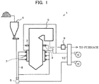
- FIG. 1 is an entire view describing a combustion system according to Embodiment 1 of the present invention.
- FIG. 1 in a combustion system (combustion device) 1 of Embodiment 1 used in a thermal power generation plant, and the like, pulverized coal (solid fuel) is housed in a bunker (fuel hopper) 4.
- the solid fuel of the bunker 4 is crushed by a mill (crusher) 5.
- the crushed fuel is supplied to a burner 7 of a boiler 6 through a fuel pipe 8 and burned.
- a plurality of burners 7 are installed in the boiler 6.
- the solid fuel is not limited to the pulverized coal, and for example, biomass fuel may also be used.
- the boiler 6 includes an additional nozzle 3 installed on a downstream side (upper side) of the burner 7 to supply a combustion air.
- FIG. 2 is a view describing the burner of Embodiment 1.
- FIG. 3 is a view as seen from an arrow III direction in FIG. 2 .
- the burner (mixed combustion burner) 7 of Embodiment 1 has a fuel nozzle 21 through which a mixed flow flows.
- the fuel nozzle 21 has an opening at a downstream end thereof, which is disposed in the vicinity of a wall surface (furnace wall, water pipe wall) 23 of a furnace 22 of the boiler 6.
- An upstream side of the fuel nozzle 21 is connected with the fuel pipe 8.
- the fuel nozzle 21 is formed in a hollow cylindrical shape.
- the fuel nozzle 21 has a flow passage 24 formed therein, through which a solid fuel (pulverized coal) and a carrier gas thereof flow.
- An inner combustion air nozzle (secondary combustion air nozzle) 26 is installed on an outer periphery of the fuel nozzle 21 to spray a combustion air to the furnace 22.
- the secondary combustion air nozzle 26 has a secondary air flow passage 11 formed therein, through which a secondary air (secondary combustion air) flows.
- an outer combustion air nozzle (tertiary combustion air nozzle) 27 is installed on an outer peripheral side of the inner combustion air nozzle 26.
- the tertiary combustion air nozzle 27 has a tertiary air flow passage 12 formed therein, through which a tertiary air (tertiary combustion air) flows.
- Each of the combustion air nozzles 26 and 27 sprays air from a wind box (wind case) 28 toward an inside of the furnace 22.
- a guide vane (second guide member) 26a is formed at the downstream end of the inner combustion air nozzle 26, which is inclined radially outward with respect to a center of the fuel nozzle 21 (a diameter thereof is increased toward the downstream side).
- the outer combustion air nozzle 27 includes a throat part 27a along an axial direction and an expansion part 27b parallel to the guide vane 26a, which are formed in the downstream portion thereof. Therefore, the combustion air sprayed from the respective combustion air nozzles 26 and 27 is sprayed so as to be diffused from the center in the axial direction (guided so as to be separated from the mixed flow of the flow passage 24).
- the inner combustion air nozzle 26 includes a slide type damper 26c installed in an upstream portion thereof to adjust the flow rate of the secondary combustion air (secondary air).
- the outer combustion air nozzle 27 includes a swirl generating device 27c installed in the upstream portion thereof to impart a swirling component to the tertiary combustion air (tertiary air).
- a flame holder 31 is installed in an opening portion of the downstream end of the fuel nozzle 21.
- the flame holder 31 includes a guide vane (first guide member) 31a formed on a radial outside thereof with extending outward in a radial direction. Therefore, the combustion air flowing through the inner combustion air nozzle 26 is guided so as to be separated to an outside in the radial direction with respect to the mixed flow flowing through the flow passage 24 by the guide vane 31a of the flame holder 31.
- a venturi 33 is installed on an inner wall surface of the fuel nozzle 21.
- the venturi 33 has a diameter contraction part 33a on the upstream side, a minimum diameter part 33b continued to the downstream side of the diameter contraction part 33a, and a diameter expansion part 33c continued to the downstream side of the minimum diameter part 33b.
- the diameter contraction part 33a an inner diameter of the flow passage 24 is reduced toward the downstream side.
- the diameter expansion part 33c the inner diameter of the flow passage 24 is increased toward the downstream side.
- the mixed fluid of the fuel and the carrier gas supplied to the fuel nozzle 21 is narrowed inward in the radial direction when passing through the diameter contraction part 33a. Therefore, it is possible to move the fuel biased in the vicinity of the inner wall surface of the fuel nozzle 21 to the center side.
- a fuel concentrator 34 is installed on the downstream side of the venturi 33.
- the fuel concentrator 34 has a diameter expansion part 34a on the upstream side, a maximum diameter part 34b continued to the downstream side of the diameter expansion part 34a, and a diameter contraction part 34c continued to the downstream side of the maximum diameter part 34b.
- An outer diameter of the diameter expansion part 34a is increased toward the downstream side.
- the outer diameter of the diameter contraction part 34c is reduced toward the downstream side.
- an ammonia supply pipe 41 is disposed on the outside of an outer wall of the wind box 28.
- a high-pressure ammonia gas (gas fuel) is supplied to the ammonia supply pipe 41.
- a plurality of ammonia supply nozzles 42 are connected to the ammonia supply pipe 41. In the present embodiment, as illustrated in FIG. 3 , eight ammonia supply nozzles 42 are disposed at an interval along a circumferential direction.
- the ammonia supply nozzle 42 has a straight tubular nozzle body 43, and a curved nozzle connection part 44 which connects the nozzle body 43 and the ammonia supply pipe 41.
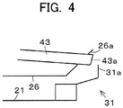
- FIG. 4 is an enlarged view of a tip portion of the ammonia supply nozzle in the burner of the present embodiment.
- FIG. 5 is a cross-sectional view of a major part of the tip portion of the ammonia supply nozzle.
- the nozzle body 43 is rotatably supported by the ammonia supply pipe 41 through a guide pipe and a seal (not illustrated) about an axial direction 43b.
- the nozzle body 43 penetrates the wall surfaces of the wind box 28, the outer combustion air nozzle 27, and the inner combustion air nozzle 26.
- a downstream end 43a of the nozzle body 43 is disposed on the downstream side of the guide vane 26a installed at the end portion of the inner combustion air nozzle 26, and on the upstream side of the guide vane 31a installed in the flame holder 31, with respect to the flow direction of the combustion air.
- FIG. 6 is a detailed view describing a connection portion between the body of the ammonia supply nozzle and the curved nozzle connection part.
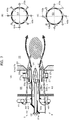
- FIG. 7 is views describing a supply direction of ammonia, wherein FIG. 7 (A) is an explanatory view corresponding to FIG. 2 , FIG. 7 (B) is an explanatory view when injecting ammonia obliquely in a central axis direction, and FIG. 7 (C) is an explanatory view when injecting ammonia obliquely deviating from a central axis.
- an injection port 43c which is inclined at an angle ⁇ with respect to the axial direction 43b is formed in the tip portion of the nozzle body 43.
- the nozzle body 43 of this embodiment is rotatably supported about the axial direction 43b with respect to a receiving part 46 fixedly supported by the connection part 44. Further, the nozzle body 43 and the connection part 44 are sealed (closed) through an O-ring 47.
- a handle 48 for adjusting rotation is installed on the nozzle body 43. By manually operating the handle 48 to adjust the rotation at the time of trial operation or maintenance, an injection direction may be freely set as illustrated in FIGS. 7 (B) and 7 (C) .
- the mixed fluid of the pulverized coal and the carrier gas is sprayed from the fuel nozzle 21 into the furnace 22.
- the combustion air is divided into an inner combustion air (secondary air) and an outer combustion air (tertiary air) to be supplied to the furnace 22.
- the secondary air is expanded to the outside by the guide vane 31a installed in the flame holder 31, and the tertiary air is expanded to the outside by the guide vane 26a installed in the inner combustion air nozzle 26 to be supplied, such that a circulation vortex 52 is formed between the mixed fluid and the outer peripheral air 51 composed of the secondary air and the tertiary air. Since a high-temperature gas in the furnace 22 is returned to an outlet part of the burner 7 by riding on a circulation flow in the circulation vortex 52, the mixed fluid is rapidly ignited in the vicinity of the outlet of the burner 7.
- the pulverized coal supplied from the fuel nozzle 21 is concentrated on the outer peripheral side (in the vicinity of the inner wall surface of the fuel nozzle) by the fuel concentrator 34 to form a pulverized coal concentrated region. Then, the high-temperature gas in the furnace 22 is returned to the vicinity of the pulverized coal concentrated region, such that rapid ignition performance is further enhanced.
- a primary combustion region 53 is formed in the vicinity of the central axis of the outlet of the burner 7. Since the outer peripheral air 51 is supplied away from the primary combustion region 53, the primary combustion region 53 becomes a reduction condition of an excessive fuel (air shortage).
- a rapid combustion reaction progresses inside the primary combustion region 53 formed from the outlet part of the burner 7.
- Oxygen (O 2 ) is rapidly consumed by the progress of combustion.
- nitrogen oxide (NO) is generated from the N component in the fuel (pulverized coal), and a hydrocarbon radical ( ⁇ HC) as an intermediate product is rapidly generated from a main component of combustion.
- a radical ( ⁇ NX) containing a nitrogen element is generated by a reaction of the generated nitrogen oxide (NO) with the hydrocarbon radical ( ⁇ HC), and NO is reduced to N 2 by a reaction of ⁇ NX with NO.
- the guide vane 31a of the flame holder 31 is installed at the tip portion of a partition wall (fuel nozzle 21) of the mixed fluid and the combustion air (outer peripheral air 51), and (the secondary air of) the outer peripheral air 51 is reliably separated from the mixed fluid. Therefore, as compared with the case in which the separation is not performed, it is possible to generate a reduction region 53 with a strong reduction condition.
- the separation of the outer peripheral air 51 from the mixed flow is also strengthened by the guide vane 26a of the inner combustion air nozzle 26.
- the swirl generating device 27c is installed in the outer combustion air nozzle 27, such that the tertiary air (outer peripheral air 51) has difficulty mixing with the mixed flow, and the separation from the mixed flow is strengthened. Therefore, as compared with the case in which the swirl generating device 27c is not provided, it is possible to generate the reduction region 53 with the strong reduction condition.
- the downstream end of the ammonia supply nozzle 42 is disposed on the upstream side of the guide vane 31a of the flame holder 31. If the ammonia supply nozzle 42 extends to the inside of the furnace 22 beyond the flame holder 31, the ammonia supply nozzle 42 may be burnt out. On the other hand, in Embodiment 1, the ammonia supply nozzle 42 is disposed on the upstream side of the guide vane 31a, is protected from the flame by the seal due to the secondary air sent from the upstream side, and is cooled by the secondary air. Therefore, the ammonia supply nozzle 42 is suppressed from being burnt out.
- the downstream end of the ammonia supply nozzle 42 is disposed on the downstream side of the guide vane 26a of the inner combustion air nozzle 26. Therefore, it is possible to supply ammonia without being affected by the flow of combustion air spreading along the guide vane 26a, and the ammonia is likely to be supplied to the reduction region.
- the injection direction of the ammonia supply nozzle 42 is configured to be adjustable. Therefore, as illustrated in FIG. 7 (A) , it is also possible to concentrate the ammonia on the central portion of the reduction region 53. Further, as illustrated in FIG. 7 (B) , it is also possible to bring the ammonia closer to an outer edge portion of the reduction region 53. Thereby, it is possible to freely adjust the concentration and dispersion of the ammonia in the reduction region 53.
- a control valve (not illustrated) is provided in the upstream portion of the ammonia supply pipe 41, thereby it is possible to control a supply amount of ammonia. Therefore, it is possible to adjust and control a ratio (mixing ratio) of the solid fuel to ammonia depending on an appropriate ratio for efficiently reducing the N component in ammonia to N 2 .
- the ratio of the pulverized coal to ammonia so that the ratio of heat input due to combustion of the ammonia is 50% or less. If the amount of the pulverized coal is reduced too much by increasing the amount of heat input of the ammonia, the flame may become unstable. Therefore, it is preferable to adjust the ratio of heat input due to the combustion of the ammonia to be 50% or less.
- the additional nozzle 3 for supplying the combustion air is installed on the downstream side of the burner 7 in the furnace 22. Therefore, it is possible to reduce a generation of nitrogen oxide in the furnace 22 by performing combustion (two-stage combustion) even after the position of the additional nozzle 3 after the combustion in the burner 7.
- the total amount of air supplied from the burner 7 (the total amount of air, secondary air and tertiary air contained in the mixed fluid from the fuel nozzle 21) is set to be a theoretical air volume or less required for the reduction reaction in the reduction region 53. Therefore, it is possible to suppress an increase in the amount of NOx generated due to a large amount of air and weakened reduction in the reduction region 53.
Landscapes
- Engineering & Computer Science (AREA)
- Mechanical Engineering (AREA)
- General Engineering & Computer Science (AREA)
- Chemical & Material Sciences (AREA)
- Combustion & Propulsion (AREA)
Abstract
Description
- The present invention relates to a burner which uses a solid fuel and a combustion device having the burner.
- In a burner to burn a solid fuel such as pulverized coal obtained by crushing coal, a technique for expanding a reduction region on a downstream side of an opening end of the burner by installing a secondary air nozzle on an outer peripheral side of a fuel nozzle to expand a secondary air by a guide vane is known in the art (
Patent Documents 1 to 3). - Further, in a burner which uses a gas fuel such as liquefied natural gas (LNG), a technique for adjusting an spray direction and an angle of the gas fuel in order to reduce NOx is also known in the art (
Patent Documents 4 and 5). - Further, a technique, in which a pulverized coal burner and a gas burner are combined in order to support operating by switching a solid fuel and a gas fuel, is also known in the art (
Patent Documents 6 and 7). -
- Patent Document 1: Japanese Unexamined Patent Application Publication No.
H04-214102 - Patent Document 2: Japanese Patent No.
3344694 - Patent Document 3: Japanese Patent No.
5794419 - Patent Document 4: Japanese Utility Model Publication No.
S56-075507 - Patent Document 5: Japanese Examined Patent Publication No.
S57-061125 - Patent Document 6: Japanese Patent No.
2526236 - Patent Document 7: Japanese Examined Patent Publication No.
H06-023607 - When ammonia (NH3) is used as a fuel, CO2 is not generated after the combustion, such that research on direct combustion of CO2-free ammonia has been carried out. As a point to be considered at the time of combustion, a general gas fuel such as natural gas as described in
Patent Documents - There is a distribution of high and low oxygen concentration in the boiler, but if ammonia can be injected into a primary combustion region (reduction region) of a solid fuel burner, which is a reduction condition at all times (see
Patent Documents 1 to 3), it is possible to stably perform mixed combustion in which an increase of NOx is suppressed. - In the configurations described in
Patent Documents Patent Documents Patent Documents - It is a technical object of the present invention to provide a burner capable of mixedly combusting a solid fuel and ammonia and a combustion device including the burner.
- The above object of the present invention may be achieved by employing the following configurations.
- An invention of a first aspect of the present invention is a burner including: a fuel supply nozzle to which a mixed flow of a solid fuel and a carrier gas for the solid fuel is supplied; a flow passage which is disposed on an outside of the fuel supply nozzle to supply a combustion air separately from the mixed flow; and an ammonia supply nozzle configured to supply ammonia toward a reduction region in which oxygen in the carrier gas is consumed by ignition and combustion progress of a fuel on a downstream side of an outlet of the fuel supply nozzle to be a low oxygen concentration.
- An invention of a second aspect of the present invention is the burner according to the first aspect of the present invention, further including a first guide member which is installed at a tip portion of a partition wall between the mixed flow and the combustion air to guide the combustion air so as to be separated from the mixed flow.
- An invention of a third aspect of the present invention is the burner according to the second aspect of the present invention, wherein the ammonia supply nozzle is provided so that a downstream end thereof is disposed on an upstream side of a flow of the combustion air with respect to the first guide member.
- An invention of a fourth aspect of the present invention is the burner according to any one of the first to third aspects of the present invention, further including a second guide member which is installed at an outlet part of the flow passage of the combustion air to strengthen a separation of an outer peripheral air from the mixed flow.
- An invention of a fifth aspect of the present invention is the burner according to the fourth aspect of the present invention, wherein the ammonia supply nozzle is provided so that a downstream end thereof is disposed on a downstream side of the flow of the combustion air with respect to the second guide member.
- An invention of a sixth aspect of the present invention is the burner according to any one of the first to fifth aspects of the present invention, further including a swirl generating device which is disposed in the flow passage of the combustion air to separate the combustion air from the mixed flow.
- An invention of a seventh aspect of the present invention is the burner according to any one of the first to sixth aspects of the present invention, wherein the ammonia supply nozzle is provided so that an injection angle of ammonia thereof is adjustable.
- An invention of an eighth aspect of the present invention is the burner according to any one of the first to seventh aspects of the present invention, wherein a ratio of heat input due to combustion of the solid fuel to heat input due to combustion of the ammonia is adjustable.
- An invention of a ninth aspect of the present invention is the burner according to the eighth aspect of the present invention, wherein the ratio of heat input due to combustion of the ammonia is 50% or less.
- An invention of a tenth aspect of the present invention is a combustion device including: a furnace in which the burner according to any one of the first to seventh aspects is installed; and an additional nozzle configured to separate and supply a part of the combustion air onto the downstream side of the burner in the furnace.
- An invention of an eleventh aspect of the present invention is the combustion device according to the tenth aspect of the present invention, wherein a total air flow rate supplied from the burner is set to be a theoretical air amount or less.
- In accordance with the invention according to the first aspect, it is possible to provide a burner capable of mixedly combusting the solid fuel and ammonia by supplying ammonia toward the reduction region, in which an increase of nitrogen oxide is suppressed, while using the ammonia as a gas fuel.
- In accordance with the invention according to the second aspect, in addition to the effect of the first aspect of the present invention, as compared with the case in which the combustion air is not separated from the mixed flow by the first guide member, it is difficult for the combustion air to be mixed in the reduction region, and it is possible to generate a reduction region with strong reduction.
- In accordance with the invention according to the third aspect, in addition to the effect of the second aspect of the present invention, as compared with the case in which the downstream end of the ammonia supply nozzle is not disposed on the upstream side of the flow of combustion air with respect to the first guide member, it is possible to suppress the ammonia supply nozzle from being burnt out.
- In accordance with the invention according to the fourth aspect, in addition to the effect of any one of the first to third aspects of the present invention, as compared with the case in which a separation of the outer peripheral air from the mixed flow is not strengthened by the second guide member, it is difficult for the combustion air to be mixed in the reduction region, and it is possible to generate a reduction region with strong reduction.
- In accordance with the invention according to the fifth aspect, ammonia may be supplied without being affected by the flow of the combustion air spreading along the second guide member, and ammonia is likely to be supplied to the reduction region.
- In accordance with the invention according to the sixth aspect, in addition to the effect of any one of the first to fifth aspects of the present invention, as compared with the case in which the outer peripheral air from the mixed flow is not separated by the swirl generating device, it is difficult for the combustion air to be mixed in the reduction region, and it is possible to generate a reduction region with strong reduction.
- In accordance with the invention according to the seventh aspect, in addition to the effect of any one of the first to sixth aspects of the present invention, it is possible to adjust the distribution of ammonia in the reduction region.
- In accordance with the invention according to the eighth aspect, in addition to the effect of any one of the first to seventh aspects of the present invention, by adjusting the ratio of heat input due to combustion of the solid fuel to heat input due to combustion of the ammonia, it is possible to suppress an increase of nitrogen oxide by optimizing the combustion.
- In accordance with the invention according to the ninth aspect, in addition to the effect of the eighth aspect of the present invention, by setting the ratio of heat input due to combustion of the ammonia to be 50% or less, it is possible to secure the flow rate of the solid fuel required for stabilizing the flame.
- In accordance with the invention according to the tenth aspect, as compared with the case in which the additional nozzle is not provided, it is possible to suppress an increase of nitrogen oxide.
- In accordance with the invention according to the eleventh aspect, in addition to the effect of the tenth aspect of the present invention, by setting the total air flow rate supplied from the burner to be the theoretical air amount or less, it is possible to suppress a reduction of the reduction action, and suppress an increase of nitrogen oxide.
-
-
FIG. 1 is an entire view describing a combustion system according toEmbodiment 1 of the present invention. -
FIG. 2 is a view describing a burner ofEmbodiment 1. -
FIG. 3 is a view as seen from an arrow III direction inFIG. 2 . -
FIG. 4 is an enlarged view of a tip portion of an ammonia supply nozzle in the burner of the present embodiment. -
FIG. 5 is a cross-sectional view of a major part of the tip portion of the ammonia supply nozzle. -
FIG. 6 is a detailed view describing a connection portion between a body of the ammonia supply nozzle and a curved nozzle connection part. -
FIG. 7 is views describing a supply direction of ammonia, whereinFIG. 7 (A) is an explanatory view corresponding toFIG. 2 ,FIG. 7 (B) is an explanatory view when injecting ammonia obliquely in a central axis direction, andFIG. 7 (C) is an explanatory view when injecting ammonia obliquely deviating from a central axis. - Hereinafter, embodiments of the present invention will be described.
-
FIG. 1 is an entire view describing a combustion system according toEmbodiment 1 of the present invention. - In
FIG. 1 , in a combustion system (combustion device) 1 ofEmbodiment 1 used in a thermal power generation plant, and the like, pulverized coal (solid fuel) is housed in a bunker (fuel hopper) 4. The solid fuel of thebunker 4 is crushed by a mill (crusher) 5. The crushed fuel is supplied to aburner 7 of aboiler 6 through afuel pipe 8 and burned. In addition, a plurality ofburners 7 are installed in theboiler 6. Further, the solid fuel is not limited to the pulverized coal, and for example, biomass fuel may also be used. - The
boiler 6 includes anadditional nozzle 3 installed on a downstream side (upper side) of theburner 7 to supply a combustion air. -
FIG. 2 is a view describing the burner ofEmbodiment 1. -
FIG. 3 is a view as seen from an arrow III direction inFIG. 2 . - In
FIGS. 2 and3 , the burner (mixed combustion burner) 7 ofEmbodiment 1 has afuel nozzle 21 through which a mixed flow flows. Thefuel nozzle 21 has an opening at a downstream end thereof, which is disposed in the vicinity of a wall surface (furnace wall, water pipe wall) 23 of afurnace 22 of theboiler 6. An upstream side of thefuel nozzle 21 is connected with thefuel pipe 8. Thefuel nozzle 21 is formed in a hollow cylindrical shape. Thefuel nozzle 21 has aflow passage 24 formed therein, through which a solid fuel (pulverized coal) and a carrier gas thereof flow. - An inner combustion air nozzle (secondary combustion air nozzle) 26 is installed on an outer periphery of the
fuel nozzle 21 to spray a combustion air to thefurnace 22. The secondarycombustion air nozzle 26 has a secondaryair flow passage 11 formed therein, through which a secondary air (secondary combustion air) flows. - Further, an outer combustion air nozzle (tertiary combustion air nozzle) 27 is installed on an outer peripheral side of the inner
combustion air nozzle 26. The tertiarycombustion air nozzle 27 has a tertiaryair flow passage 12 formed therein, through which a tertiary air (tertiary combustion air) flows. - Each of the
combustion air nozzles furnace 22. InEmbodiment 1, a guide vane (second guide member) 26a is formed at the downstream end of the innercombustion air nozzle 26, which is inclined radially outward with respect to a center of the fuel nozzle 21 (a diameter thereof is increased toward the downstream side). In addition, the outercombustion air nozzle 27 includes a throat part 27a along an axial direction and anexpansion part 27b parallel to theguide vane 26a, which are formed in the downstream portion thereof. Therefore, the combustion air sprayed from the respectivecombustion air nozzles - In
FIG. 2 , the innercombustion air nozzle 26 includes aslide type damper 26c installed in an upstream portion thereof to adjust the flow rate of the secondary combustion air (secondary air). - In addition, the outer
combustion air nozzle 27 includes aswirl generating device 27c installed in the upstream portion thereof to impart a swirling component to the tertiary combustion air (tertiary air). - Further, a
flame holder 31 is installed in an opening portion of the downstream end of thefuel nozzle 21. Theflame holder 31 includes a guide vane (first guide member) 31a formed on a radial outside thereof with extending outward in a radial direction. Therefore, the combustion air flowing through the innercombustion air nozzle 26 is guided so as to be separated to an outside in the radial direction with respect to the mixed flow flowing through theflow passage 24 by theguide vane 31a of theflame holder 31. - In
FIG. 2 , aventuri 33 is installed on an inner wall surface of thefuel nozzle 21. Theventuri 33 has adiameter contraction part 33a on the upstream side, aminimum diameter part 33b continued to the downstream side of thediameter contraction part 33a, and adiameter expansion part 33c continued to the downstream side of theminimum diameter part 33b. In thediameter contraction part 33a, an inner diameter of theflow passage 24 is reduced toward the downstream side. In addition, in thediameter expansion part 33c, the inner diameter of theflow passage 24 is increased toward the downstream side. - Therefore, in the
venturi 33 ofEmbodiment 1, the mixed fluid of the fuel and the carrier gas supplied to thefuel nozzle 21 is narrowed inward in the radial direction when passing through thediameter contraction part 33a. Therefore, it is possible to move the fuel biased in the vicinity of the inner wall surface of thefuel nozzle 21 to the center side. - A
fuel concentrator 34 is installed on the downstream side of theventuri 33. Thefuel concentrator 34 has adiameter expansion part 34a on the upstream side, amaximum diameter part 34b continued to the downstream side of thediameter expansion part 34a, and adiameter contraction part 34c continued to the downstream side of themaximum diameter part 34b. An outer diameter of thediameter expansion part 34a is increased toward the downstream side. The outer diameter of thediameter contraction part 34c is reduced toward the downstream side. - Therefore, in the
fuel concentrator 34 ofEmbodiment 1, a velocity component toward the outer side in the radial direction is imparted to the mixed fluid of the fuel and the carrier gas when passing through thediameter expansion part 34a. Thereby, the fuel is condensed toward the inner wall surface of thefuel nozzle 21. - In
FIG. 2 , anammonia supply pipe 41 is disposed on the outside of an outer wall of thewind box 28. A high-pressure ammonia gas (gas fuel) is supplied to theammonia supply pipe 41. A plurality ofammonia supply nozzles 42 are connected to theammonia supply pipe 41. In the present embodiment, as illustrated inFIG. 3 , eightammonia supply nozzles 42 are disposed at an interval along a circumferential direction. - The
ammonia supply nozzle 42 has a straighttubular nozzle body 43, and a curvednozzle connection part 44 which connects thenozzle body 43 and theammonia supply pipe 41. -
FIG. 4 is an enlarged view of a tip portion of the ammonia supply nozzle in the burner of the present embodiment. -
FIG. 5 is a cross-sectional view of a major part of the tip portion of the ammonia supply nozzle. - In
FIG. 2 , thenozzle body 43 is rotatably supported by theammonia supply pipe 41 through a guide pipe and a seal (not illustrated) about anaxial direction 43b. Thenozzle body 43 penetrates the wall surfaces of thewind box 28, the outercombustion air nozzle 27, and the innercombustion air nozzle 26. InFIGS. 2 and4 , adownstream end 43a of thenozzle body 43 is disposed on the downstream side of theguide vane 26a installed at the end portion of the innercombustion air nozzle 26, and on the upstream side of theguide vane 31a installed in theflame holder 31, with respect to the flow direction of the combustion air. -
FIG. 6 is a detailed view describing a connection portion between the body of the ammonia supply nozzle and the curved nozzle connection part. -
FIG. 7 is views describing a supply direction of ammonia, whereinFIG. 7 (A) is an explanatory view corresponding toFIG. 2 ,FIG. 7 (B) is an explanatory view when injecting ammonia obliquely in a central axis direction, andFIG. 7 (C) is an explanatory view when injecting ammonia obliquely deviating from a central axis. - In
FIG. 5 , aninjection port 43c which is inclined at an angle θ with respect to theaxial direction 43b is formed in the tip portion of thenozzle body 43. In addition, inFIG. 6 , thenozzle body 43 of this embodiment is rotatably supported about theaxial direction 43b with respect to a receivingpart 46 fixedly supported by theconnection part 44. Further, thenozzle body 43 and theconnection part 44 are sealed (closed) through an O-ring 47. Ahandle 48 for adjusting rotation is installed on thenozzle body 43. By manually operating thehandle 48 to adjust the rotation at the time of trial operation or maintenance, an injection direction may be freely set as illustrated inFIGS. 7 (B) and 7 (C) . - In the
burner 7 ofEmbodiment 1 having the above-described configuration, the mixed fluid of the pulverized coal and the carrier gas is sprayed from thefuel nozzle 21 into thefurnace 22. In addition, the combustion air is divided into an inner combustion air (secondary air) and an outer combustion air (tertiary air) to be supplied to thefurnace 22. The secondary air is expanded to the outside by theguide vane 31a installed in theflame holder 31, and the tertiary air is expanded to the outside by theguide vane 26a installed in the innercombustion air nozzle 26 to be supplied, such that acirculation vortex 52 is formed between the mixed fluid and the outerperipheral air 51 composed of the secondary air and the tertiary air. Since a high-temperature gas in thefurnace 22 is returned to an outlet part of theburner 7 by riding on a circulation flow in thecirculation vortex 52, the mixed fluid is rapidly ignited in the vicinity of the outlet of theburner 7. - Herein, the pulverized coal supplied from the
fuel nozzle 21 is concentrated on the outer peripheral side (in the vicinity of the inner wall surface of the fuel nozzle) by thefuel concentrator 34 to form a pulverized coal concentrated region. Then, the high-temperature gas in thefurnace 22 is returned to the vicinity of the pulverized coal concentrated region, such that rapid ignition performance is further enhanced. - Due to the rapid ignition, a
primary combustion region 53 is formed in the vicinity of the central axis of the outlet of theburner 7. Since the outerperipheral air 51 is supplied away from theprimary combustion region 53, theprimary combustion region 53 becomes a reduction condition of an excessive fuel (air shortage). - Specifically, due to the rapid ignition, a rapid combustion reaction progresses inside the
primary combustion region 53 formed from the outlet part of theburner 7. Oxygen (O2) is rapidly consumed by the progress of combustion. Then, nitrogen oxide (NO) is generated from the N component in the fuel (pulverized coal), and a hydrocarbon radical (·HC) as an intermediate product is rapidly generated from a main component of combustion. Under a condition of strengthening reduction after O2 is decreased, a radical (·NX) containing a nitrogen element is generated by a reaction of the generated nitrogen oxide (NO) with the hydrocarbon radical (·HC), and NO is reduced to N2 by a reaction of ·NX with NO. - When ammonia (NH3) is sprayed into this reduction region (primary combustion region) 53, a reduction reaction to N2 progresses preferentially through the NH radical.
- Therefore, in the
burner 7 ofEmbodiment 1, an increase of nitrogen oxide is suppressed while mixedly combusting the solid fuel and ammonia. - Further, in the
burner 7 ofEmbodiment 1, theguide vane 31a of theflame holder 31 is installed at the tip portion of a partition wall (fuel nozzle 21) of the mixed fluid and the combustion air (outer peripheral air 51), and (the secondary air of) the outerperipheral air 51 is reliably separated from the mixed fluid. Therefore, as compared with the case in which the separation is not performed, it is possible to generate areduction region 53 with a strong reduction condition. - Further, in the
burner 7 ofEmbodiment 1, the separation of the outerperipheral air 51 from the mixed flow is also strengthened by theguide vane 26a of the innercombustion air nozzle 26. Thereby, as compared with the case in which theguide vane 26a is not provided, it is possible to generate thereduction region 53 with the strong reduction condition. - In addition, in the
burner 7 ofEmbodiment 1, theswirl generating device 27c is installed in the outercombustion air nozzle 27, such that the tertiary air (outer peripheral air 51) has difficulty mixing with the mixed flow, and the separation from the mixed flow is strengthened. Therefore, as compared with the case in which theswirl generating device 27c is not provided, it is possible to generate thereduction region 53 with the strong reduction condition. - Further, in the
burner 7 ofEmbodiment 1, the downstream end of theammonia supply nozzle 42 is disposed on the upstream side of theguide vane 31a of theflame holder 31. If theammonia supply nozzle 42 extends to the inside of thefurnace 22 beyond theflame holder 31, theammonia supply nozzle 42 may be burnt out. On the other hand, inEmbodiment 1, theammonia supply nozzle 42 is disposed on the upstream side of theguide vane 31a, is protected from the flame by the seal due to the secondary air sent from the upstream side, and is cooled by the secondary air. Therefore, theammonia supply nozzle 42 is suppressed from being burnt out. - Furthermore, in the
burner 7 ofEmbodiment 1, the downstream end of theammonia supply nozzle 42 is disposed on the downstream side of theguide vane 26a of the innercombustion air nozzle 26. Therefore, it is possible to supply ammonia without being affected by the flow of combustion air spreading along theguide vane 26a, and the ammonia is likely to be supplied to the reduction region. - In addition, in the
burner 7 ofEmbodiment 1, the injection direction of theammonia supply nozzle 42 is configured to be adjustable. Therefore, as illustrated inFIG. 7 (A) , it is also possible to concentrate the ammonia on the central portion of thereduction region 53. Further, as illustrated inFIG. 7 (B) , it is also possible to bring the ammonia closer to an outer edge portion of thereduction region 53. Thereby, it is possible to freely adjust the concentration and dispersion of the ammonia in thereduction region 53. Therefore, depending on the use environment such as a type of the pulverized coal used, a ratio of the N component, an amount of combustion air, etc., and depending on an appropriate degree of dispersion for efficiently reducing the N component in ammonia to N2, it is possible to adjust the injection direction. - Further, in
Embodiment 1, a control valve (not illustrated) is provided in the upstream portion of theammonia supply pipe 41, thereby it is possible to control a supply amount of ammonia. Therefore, it is possible to adjust and control a ratio (mixing ratio) of the solid fuel to ammonia depending on an appropriate ratio for efficiently reducing the N component in ammonia to N2. - In particular, it is preferable to control the ratio of the pulverized coal to ammonia so that the ratio of heat input due to combustion of the ammonia is 50% or less. If the amount of the pulverized coal is reduced too much by increasing the amount of heat input of the ammonia, the flame may become unstable. Therefore, it is preferable to adjust the ratio of heat input due to the combustion of the ammonia to be 50% or less.
- Further, in
Embodiment 1, theadditional nozzle 3 for supplying the combustion air is installed on the downstream side of theburner 7 in thefurnace 22. Therefore, it is possible to reduce a generation of nitrogen oxide in thefurnace 22 by performing combustion (two-stage combustion) even after the position of theadditional nozzle 3 after the combustion in theburner 7. - Furthermore, in
Embodiment 1, the total amount of air supplied from the burner 7 (the total amount of air, secondary air and tertiary air contained in the mixed fluid from the fuel nozzle 21) is set to be a theoretical air volume or less required for the reduction reaction in thereduction region 53. Therefore, it is possible to suppress an increase in the amount of NOx generated due to a large amount of air and weakened reduction in thereduction region 53. - Although the embodiments of the present invention have been described above in detail, the present invention is not limited to the above-described embodiments, and various modifications may be made within the scope of the present invention described in the claims. Modifications (H01) to (H04) of the present invention will be described as examples below.
- (H01) In the above-described embodiment, it is preferable that the
ammonia supply nozzle 42 has a configuration in which the injection direction can be adjusted, but it is not limited thereto. It is also possible to have a configuration in which the injection direction cannot be adjusted. In addition, the configuration, in which the injection direction is adjusted by rotating thenozzle body 43, has been exemplified, but it is not limited thereto. For example, it is possible to employ an arbitrary configuration such as a configuration in which a plurality of injection ports are formed in the tip portion, each injection port is configured to be opened and closed by shutters, and the shutters are opened and closed depending on the injection direction. - (H02) In the above-described embodiment, it is preferable that the downstream end of the
ammonia supply nozzle 42 is on the upstream side of theguide vane 31a of theflame holder 31, and on the downstream side of theguide vane 26a of the innercombustion air nozzle 26, but it is not limited thereto. After taking measures against burning out, the downstream end thereof may be disposed on the downstream side of theguide vane 31a of theflame holder 31, or on the upstream side of theguide vane 26a of the innercombustion air nozzle 26 by increasing the injection pressure of ammonia. - (H03) In the above-described embodiment, it is preferable to provide the
swirl generating device 27c, but a configuration, in which the swirl generating device is not provided, is also possible. In addition, the configuration, in which theswirl generating device 27c is installed in the upstream portion of the outercombustion air nozzle 27, has been exemplified, but it may also be provided in the downstream portion (near the outlet) thereof. - (H04) In the above-described embodiment, the shapes and sizes of the
guide vanes guide vanes -
- 1...Combustion device,
- 3...Additional nozzle,
- 7...Burner,
- 21...Fuel supply nozzle,
- 22...Furnace,
- 26, 27...Combustion air nozzle,
- 26a...Second guide member,
- 27c...Swirl generating device,
- 31a...First guide member,
- 42...Ammonia supply nozzle,
- 53...Reduction region.
Claims (11)
- A burner comprising:a fuel supply nozzle to which a mixed flow of a solid fuel and a carrier gas for the solid fuel is supplied;a flow passage which is disposed on an outside of the fuel supply nozzle to supply a combustion air separately from the mixed flow; andan ammonia supply nozzle configured to supply ammonia toward a reduction region in which oxygen in the carrier gas is consumed by ignition and combustion progress of a fuel on a downstream side of an outlet of the fuel supply nozzle to be a low oxygen concentration.
- The burner according to claim 1, further comprising a first guide member which is installed at a tip portion of a partition wall between the mixed flow and the combustion air to guide the combustion air so as to be separated from the mixed flow.
- The burner according to claim 2, wherein the ammonia supply nozzle is provided so that a downstream end thereof is disposed on an upstream side of a flow of the combustion air with respect to the first guide member.
- The burner according to any one of claims 1 to 3, further comprising a second guide member which is installed at an outlet part of the flow passage of the combustion air to strengthen a separation of an outer peripheral air from the mixed flow.
- The burner according to claim 4, wherein the ammonia supply nozzle is provided so that a downstream end thereof is disposed on a downstream side of the flow of the combustion air with respect to the second guide member.
- The burner according to any one of claims 1 to 5, further comprising a swirl generating device which is disposed in the flow passage of the combustion air to separate the combustion air from the mixed flow.
- The burner according to any one of claims 1 to 6, wherein the ammonia supply nozzle is provided so that an injection angle of ammonia thereof is adjustable.
- The burner according to any one of claims 1 to 7, wherein a ratio of heat input due to combustion of the solid fuel to heat input due to combustion of the ammonia is adjustable.
- The burner according to claim 8, wherein the ratio of heat input due to combustion of the ammonia is 50% or less.
- A combustion device comprising:a furnace in which the burner according to any one of claims 1 to 7 is installed; andan additional nozzle configured to separate and supply a part of the combustion air onto the downstream side of the burner in the furnace.
- The combustion device according to claim 10, wherein a total air flow rate supplied from the burner is set to be a theoretical air amount or less.
Applications Claiming Priority (2)
| Application Number | Priority Date | Filing Date | Title |
|---|---|---|---|
| JP2018098016A JP6813533B2 (en) | 2018-05-22 | 2018-05-22 | Burner and combustion equipment |
| PCT/JP2019/018938 WO2019225382A1 (en) | 2018-05-22 | 2019-05-13 | Burner and combustion device |
Publications (2)
| Publication Number | Publication Date |
|---|---|
| EP3798514A1 true EP3798514A1 (en) | 2021-03-31 |
| EP3798514A4 EP3798514A4 (en) | 2022-06-08 |
Family
ID=68616363
Family Applications (1)
| Application Number | Title | Priority Date | Filing Date |
|---|---|---|---|
| EP19807983.2A Withdrawn EP3798514A4 (en) | 2018-05-22 | 2019-05-13 | BURNER AND COMBUSTER |
Country Status (8)
| Country | Link |
|---|---|
| US (1) | US11649962B2 (en) |
| EP (1) | EP3798514A4 (en) |
| JP (1) | JP6813533B2 (en) |
| KR (1) | KR102477515B1 (en) |
| CN (1) | CN112119261B (en) |
| AU (1) | AU2019273201B2 (en) |
| CA (1) | CA3100844C (en) |
| WO (1) | WO2019225382A1 (en) |
Cited By (2)
| Publication number | Priority date | Publication date | Assignee | Title |
|---|---|---|---|---|
| EP4459184A4 (en) * | 2021-12-27 | 2025-12-03 | Kawasaki Heavy Ind Ltd | BURNER AND COMBUSTION STOVE |
| EP4459185A4 (en) * | 2021-12-27 | 2025-12-03 | Kawasaki Heavy Ind Ltd | BURNER AND COMBUSTION STOVE |
Families Citing this family (36)
| Publication number | Priority date | Publication date | Assignee | Title |
|---|---|---|---|---|
| JP7538706B2 (en) * | 2020-12-09 | 2024-08-22 | 川崎重工業株式会社 | Burner and its operating method, and combustion furnace and its operating method |
| JP7498654B2 (en) * | 2020-12-09 | 2024-06-12 | 川崎重工業株式会社 | Burner, its control method, and combustion furnace |
| JP7533754B2 (en) * | 2021-02-19 | 2024-08-14 | 株式会社Ihi | Combustion equipment and boilers |
| WO2022176353A1 (en) * | 2021-02-19 | 2022-08-25 | 株式会社Ihi | Combustion device and boiler |
| WO2022176347A1 (en) * | 2021-02-19 | 2022-08-25 | 株式会社Ihi | Combustion device and boiler |
| JP7369158B2 (en) * | 2021-03-31 | 2023-10-25 | 三菱重工業株式会社 | Ammonia fuel boiler and ammonia supply system |
| CN112879942A (en) * | 2021-03-31 | 2021-06-01 | 西安热工研究院有限公司 | Ammonia-mixed fuel thermal power generation system and method |
| JP7672917B2 (en) * | 2021-08-20 | 2025-05-08 | 三菱重工業株式会社 | FUEL SUPPLY DEVICE AND METHOD FOR CONTROLLING FUEL SUPPLY DEVICE |
| CN113864783B (en) * | 2021-09-06 | 2022-08-05 | 清华大学 | Ammonia fuel fast pyrolysis grading injection gun |
| JP7691894B2 (en) * | 2021-09-09 | 2025-06-12 | 中外炉工業株式会社 | Combustion equipment |
| JP2023039683A (en) * | 2021-09-09 | 2023-03-22 | 中外炉工業株式会社 | Ammonia fuel combustion device |
| WO2023062876A1 (en) * | 2021-10-14 | 2023-04-20 | 株式会社Ihi | Combustion device and boiler |
| JP7825416B2 (en) * | 2021-12-23 | 2026-03-06 | 三菱重工業株式会社 | Ammonia combustion burner, boiler, and boiler operation method |
| JP7775337B2 (en) * | 2021-12-24 | 2025-11-25 | 三菱重工業株式会社 | Burner, boiler equipped with same, and burner operating method |
| TWI850917B (en) * | 2021-12-24 | 2024-08-01 | 日商三菱重工業股份有限公司 | Burner, boiler equipped with the same, and burner operation method |
| CN114278940A (en) * | 2022-01-30 | 2022-04-05 | 烟台龙源电力技术股份有限公司 | Burners and Combustion Systems |
| CN114278939A (en) * | 2022-01-30 | 2022-04-05 | 烟台龙源电力技术股份有限公司 | Burner and combustion system |
| KR102583225B1 (en) | 2022-02-07 | 2023-09-25 | 두산에너빌리티 주식회사 | Micromixer and gas turbine comprising the same |
| CN114484438B (en) * | 2022-02-18 | 2025-03-18 | 上海交通大学 | A dual-purpose burner device for coal and ammonia |
| KR102645081B1 (en) * | 2022-03-15 | 2024-03-07 | 두산에너빌리티 주식회사 | Burner and boiler equipment including the same |
| CN114811584B (en) * | 2022-03-30 | 2025-06-27 | 沈阳工程学院 | A Brownian cyclonic flow composite anode plasma porous medium burner |
| KR102713399B1 (en) | 2022-05-03 | 2024-10-08 | 한국전력공사 | Combustion device for boiler and ammonia burner |
| CN114893767B (en) * | 2022-05-10 | 2023-03-10 | 华中科技大学 | A kind of ammonia-doped swirl burner with baffle structure |
| CN115095863B (en) * | 2022-06-01 | 2025-04-18 | 北京天地融创科技股份有限公司 | A multi-stage ammonia-blended reverse-injection swirl burner and a method of using the same |
| JP2024042828A (en) * | 2022-09-16 | 2024-03-29 | 三菱重工業株式会社 | Coal-ammonium mixed combustion boiler control device, coal-ammonium mixed combustion boiler control method, and coal-ammonium mixed combustion boiler control program |
| CN115823583A (en) * | 2022-11-29 | 2023-03-21 | 烟台龙源电力技术股份有限公司 | Pulverized coal and ammonia mixed combustion system and boiler |
| KR20240096201A (en) | 2022-12-19 | 2024-06-26 | 재단법인 포항산업과학연구원 | Plasma Burner, Combustion System and Operation Method thereof |
| KR102821855B1 (en) * | 2023-05-08 | 2025-06-16 | 두산에너빌리티 주식회사 | Combined combustion burner, combustor including the same |
| JP7494358B1 (en) | 2023-05-19 | 2024-06-03 | 株式会社Ihi汎用ボイラ | Dual-fuel burners and boilers |
| JP2024168313A (en) | 2023-05-23 | 2024-12-05 | 川崎重工業株式会社 | Burners and furnaces |
| JPWO2024262596A1 (en) * | 2023-06-21 | 2024-12-26 | ||
| JPWO2024262605A1 (en) * | 2023-06-21 | 2024-12-26 | ||
| JP2025024428A (en) | 2023-08-07 | 2025-02-20 | 川崎重工業株式会社 | Burners and furnaces |
| CN117588753B (en) * | 2023-11-21 | 2025-12-26 | 清华大学 | A multi-stage micro-decomposition swirl burner for ammonia-blended fuel and a low NOx control method |
| KR102787546B1 (en) * | 2023-12-11 | 2025-04-01 | 한국내화 주식회사 | Flow control system using a fuel supply line containing multiple pipes |
| CN119532735B (en) * | 2024-12-12 | 2025-09-16 | 天津大学 | A swirl burner for ammonia-coal mixed combustion and its use method |
Family Cites Families (26)
| Publication number | Priority date | Publication date | Assignee | Title |
|---|---|---|---|---|
| JPS5675507U (en) | 1979-11-15 | 1981-06-20 | ||
| JPS5675507A (en) | 1979-11-21 | 1981-06-22 | Sumitomo Metal Ind Ltd | Regenerating method of converter slag |
| DE3021875C2 (en) * | 1980-06-11 | 1985-04-25 | L. & C. Steinmüller GmbH, 5270 Gummersbach | Method for applying the selective reduction of nitrogen oxides from flame combustion with the aid of ammonia |
| JPS5726308A (en) | 1980-07-24 | 1982-02-12 | Babcock Hitachi Kk | Burner device |
| JPS5761125A (en) | 1980-09-30 | 1982-04-13 | Komatsu Ltd | Oil pressure circuit for construction machinery |
| US4519993A (en) * | 1982-02-16 | 1985-05-28 | Mcgill Incorporated | Process of conversion for disposal of chemically bound nitrogen in industrial waste gas streams |
| AU577366B2 (en) * | 1984-04-27 | 1988-09-22 | Foster Wheeler Energy Corporation | Controlled flow, split stream burner assembly with sorbent injection |
| JP2526236B2 (en) * | 1987-02-27 | 1996-08-21 | バブコツク日立株式会社 | Ultra low NOx combustion device |
| US4915619A (en) | 1988-05-05 | 1990-04-10 | The Babcock & Wilcox Company | Burner for coal, oil or gas firing |
| JP2804182B2 (en) | 1990-03-07 | 1998-09-24 | 株式会社日立製作所 | Pulverized coal boiler and pulverized coal burner |
| JPH0623607A (en) | 1992-07-08 | 1994-02-01 | Nisshinbo Ind Inc | Holder for cutting tool |
| JP3272447B2 (en) * | 1993-03-10 | 2002-04-08 | 三菱重工業株式会社 | Burner for gas fuel |
| DE4395243T1 (en) * | 1993-11-08 | 1996-11-21 | Ivo International Oy | Method and device for burning powdered fuel |
| AU709979B2 (en) * | 1996-07-19 | 1999-09-09 | Mitsubishi Hitachi Power Systems, Ltd. | Combustion burner and combustion device provided with same |
| JP3344694B2 (en) | 1997-07-24 | 2002-11-11 | 株式会社日立製作所 | Pulverized coal combustion burner |
| JP3924089B2 (en) * | 1999-04-28 | 2007-06-06 | 株式会社日立製作所 | Pulverized coal burner and combustion apparatus using pulverized coal burner |
| JP2002115810A (en) * | 2000-10-12 | 2002-04-19 | Babcock Hitachi Kk | LOW NOx SOLID FUEL COMBUSTION APPARATUS |
| US6883444B2 (en) * | 2001-04-23 | 2005-04-26 | N-Viro International Corporation | Processes and systems for using biomineral by-products as a fuel and for NOx removal at coal burning power plants |
| JP3924150B2 (en) * | 2001-10-26 | 2007-06-06 | 三菱重工業株式会社 | Gas combustion treatment method and apparatus |
| JP3890497B2 (en) * | 2002-02-14 | 2007-03-07 | 株式会社日立製作所 | Solid fuel burner and combustion method of solid fuel burner |
| US6694900B2 (en) * | 2001-12-14 | 2004-02-24 | General Electric Company | Integration of direct combustion with gasification for reduction of NOx emissions |
| US20040063053A1 (en) * | 2002-09-26 | 2004-04-01 | Monro Richard J. | Combustion process with a preferential injection of a chemical for pollutant reduction |
| JP2004301372A (en) * | 2003-03-28 | 2004-10-28 | Osaka Gas Co Ltd | Combustion equipment |
| JP5812740B2 (en) * | 2011-07-25 | 2015-11-17 | 三菱日立パワーシステムズ株式会社 | Oxyfuel combustion system and operating method thereof |
| JP5794419B2 (en) | 2011-07-29 | 2015-10-14 | 三菱日立パワーシステムズ株式会社 | Solid fuel burner |
| WO2019058563A1 (en) * | 2017-09-25 | 2019-03-28 | 中国電力株式会社 | Combustion apparatus and combustion method |
-
2018
- 2018-05-22 JP JP2018098016A patent/JP6813533B2/en active Active
-
2019
- 2019-05-13 AU AU2019273201A patent/AU2019273201B2/en active Active
- 2019-05-13 WO PCT/JP2019/018938 patent/WO2019225382A1/en not_active Ceased
- 2019-05-13 US US17/056,124 patent/US11649962B2/en active Active
- 2019-05-13 CA CA3100844A patent/CA3100844C/en active Active
- 2019-05-13 EP EP19807983.2A patent/EP3798514A4/en not_active Withdrawn
- 2019-05-13 KR KR1020207036742A patent/KR102477515B1/en active Active
- 2019-05-13 CN CN201980032296.6A patent/CN112119261B/en active Active
Cited By (2)
| Publication number | Priority date | Publication date | Assignee | Title |
|---|---|---|---|---|
| EP4459184A4 (en) * | 2021-12-27 | 2025-12-03 | Kawasaki Heavy Ind Ltd | BURNER AND COMBUSTION STOVE |
| EP4459185A4 (en) * | 2021-12-27 | 2025-12-03 | Kawasaki Heavy Ind Ltd | BURNER AND COMBUSTION STOVE |
Also Published As
| Publication number | Publication date |
|---|---|
| JP6813533B2 (en) | 2021-01-13 |
| EP3798514A4 (en) | 2022-06-08 |
| KR102477515B1 (en) | 2022-12-15 |
| WO2019225382A1 (en) | 2019-11-28 |
| US11649962B2 (en) | 2023-05-16 |
| JP2019203631A (en) | 2019-11-28 |
| CN112119261A (en) | 2020-12-22 |
| US20210364163A1 (en) | 2021-11-25 |
| CA3100844C (en) | 2022-07-05 |
| CA3100844A1 (en) | 2019-11-28 |
| CN112119261B (en) | 2023-10-27 |
| AU2019273201A1 (en) | 2021-01-07 |
| AU2019273201B2 (en) | 2022-07-28 |
| KR20210011431A (en) | 2021-02-01 |
Similar Documents
| Publication | Publication Date | Title |
|---|---|---|
| CA3100844C (en) | Burner and combustion device | |
| DK2829800T3 (en) | Coal dust / biomass mixed-incinerator and fuel combustion process | |
| DK2829796T3 (en) | Burner for mixed combustion of powdered coal and biomass and fuel combustion method | |
| US9097426B2 (en) | Burner and fuel lance for a gas turbine installation | |
| TWI272357B (en) | NOx-reduced combustion of concentrated coal streams | |
| US5407347A (en) | Apparatus and method for reducing NOx, CO and hydrocarbon emissions when burning gaseous fuels | |
| ZA200709079B (en) | Pulverized solid fuel burner | |
| JPS60226609A (en) | Combustion device for coal | |
| CA2167320C (en) | Apparatus and method for reducing nox, co and hydrocarbon emissions when burning gaseous fuels | |
| JP5399750B2 (en) | Pulverized coal combustion apparatus and pulverized coal combustion method using pulverized coal combustion apparatus | |
| JPS6280413A (en) | Low nox combustion device for solid fuel | |
| RU2585347C1 (en) | Vortex furnace | |
| JPH0535323B2 (en) |
Legal Events
| Date | Code | Title | Description |
|---|---|---|---|
| STAA | Information on the status of an ep patent application or granted ep patent |
Free format text: STATUS: THE INTERNATIONAL PUBLICATION HAS BEEN MADE |
|
| PUAI | Public reference made under article 153(3) epc to a published international application that has entered the european phase |
Free format text: ORIGINAL CODE: 0009012 |
|
| STAA | Information on the status of an ep patent application or granted ep patent |
Free format text: STATUS: REQUEST FOR EXAMINATION WAS MADE |
|
| 17P | Request for examination filed |
Effective date: 20201216 |
|
| AK | Designated contracting states |
Kind code of ref document: A1 Designated state(s): AL AT BE BG CH CY CZ DE DK EE ES FI FR GB GR HR HU IE IS IT LI LT LU LV MC MK MT NL NO PL PT RO RS SE SI SK SM TR |
|
| AX | Request for extension of the european patent |
Extension state: BA ME |
|
| DAV | Request for validation of the european patent (deleted) | ||
| DAX | Request for extension of the european patent (deleted) | ||
| A4 | Supplementary search report drawn up and despatched |
Effective date: 20220509 |
|
| RIC1 | Information provided on ipc code assigned before grant |
Ipc: F23J 7/00 20060101ALI20220502BHEP Ipc: F23D 1/00 20060101ALI20220502BHEP Ipc: F23C 99/00 20060101ALI20220502BHEP Ipc: F23C 1/12 20060101ALI20220502BHEP Ipc: F23D 17/00 20060101AFI20220502BHEP |
|
| RAP1 | Party data changed (applicant data changed or rights of an application transferred) |
Owner name: MITSUBISHI HEAVY INDUSTRIES, LTD. |
|
| GRAP | Despatch of communication of intention to grant a patent |
Free format text: ORIGINAL CODE: EPIDOSNIGR1 |
|
| STAA | Information on the status of an ep patent application or granted ep patent |
Free format text: STATUS: GRANT OF PATENT IS INTENDED |
|
| RIC1 | Information provided on ipc code assigned before grant |
Ipc: F23J 7/00 20060101ALI20240106BHEP Ipc: F23D 1/00 20060101ALI20240106BHEP Ipc: F23C 99/00 20060101ALI20240106BHEP Ipc: F23C 1/12 20060101ALI20240106BHEP Ipc: F23D 17/00 20060101AFI20240106BHEP |
|
| INTG | Intention to grant announced |
Effective date: 20240124 |
|
| RIN1 | Information on inventor provided before grant (corrected) |
Inventor name: KITAKAZE, KOSUKE Inventor name: TANIGUCHI, HITOSHI Inventor name: OCHI, KENICHI Inventor name: YAMAUCHI, YASUHIRO Inventor name: KIYAMA, KENJI |
|
| STAA | Information on the status of an ep patent application or granted ep patent |
Free format text: STATUS: THE APPLICATION IS DEEMED TO BE WITHDRAWN |
|
| 18D | Application deemed to be withdrawn |
Effective date: 20240525 |