EP3798019A1 - Pneumatic tire - Google Patents
Pneumatic tire Download PDFInfo
- Publication number
- EP3798019A1 EP3798019A1 EP20192614.4A EP20192614A EP3798019A1 EP 3798019 A1 EP3798019 A1 EP 3798019A1 EP 20192614 A EP20192614 A EP 20192614A EP 3798019 A1 EP3798019 A1 EP 3798019A1
- Authority
- EP
- European Patent Office
- Prior art keywords
- apex rubber
- tire
- rubber
- radially
- bead
- Prior art date
- Legal status (The legal status is an assumption and is not a legal conclusion. Google has not performed a legal analysis and makes no representation as to the accuracy of the status listed.)
- Granted
Links
- 239000011324 bead Substances 0.000 claims abstract description 64
- 230000001965 increasing effect Effects 0.000 description 6
- 230000000694 effects Effects 0.000 description 4
- 238000005096 rolling process Methods 0.000 description 4
- 230000000052 comparative effect Effects 0.000 description 3
- 230000003014 reinforcing effect Effects 0.000 description 3
- 239000000446 fuel Substances 0.000 description 2
- 238000005299 abrasion Methods 0.000 description 1
- 230000002411 adverse Effects 0.000 description 1
- 239000010426 asphalt Substances 0.000 description 1
- 238000005452 bending Methods 0.000 description 1
- 230000006866 deterioration Effects 0.000 description 1
- 230000002542 deteriorative effect Effects 0.000 description 1
- 238000010586 diagram Methods 0.000 description 1
- 230000002708 enhancing effect Effects 0.000 description 1
- 238000011835 investigation Methods 0.000 description 1
- 238000000034 method Methods 0.000 description 1
- 238000011056 performance test Methods 0.000 description 1
- 230000001012 protector Effects 0.000 description 1
- 230000001105 regulatory effect Effects 0.000 description 1
- 230000004043 responsiveness Effects 0.000 description 1
- 230000001052 transient effect Effects 0.000 description 1
Images


Classifications
-
- B—PERFORMING OPERATIONS; TRANSPORTING
- B60—VEHICLES IN GENERAL
- B60C—VEHICLE TYRES; TYRE INFLATION; TYRE CHANGING; CONNECTING VALVES TO INFLATABLE ELASTIC BODIES IN GENERAL; DEVICES OR ARRANGEMENTS RELATED TO TYRES
- B60C3/00—Tyres characterised by the transverse section
- B60C3/04—Tyres characterised by the transverse section characterised by the relative dimensions of the section, e.g. low profile
-
- B—PERFORMING OPERATIONS; TRANSPORTING
- B60—VEHICLES IN GENERAL
- B60C—VEHICLE TYRES; TYRE INFLATION; TYRE CHANGING; CONNECTING VALVES TO INFLATABLE ELASTIC BODIES IN GENERAL; DEVICES OR ARRANGEMENTS RELATED TO TYRES
- B60C15/00—Tyre beads, e.g. ply turn-up or overlap
- B60C15/0009—Tyre beads, e.g. ply turn-up or overlap features of the carcass terminal portion
- B60C15/0063—Tyre beads, e.g. ply turn-up or overlap features of the carcass terminal portion with ply turn-up portion diverging from carcass main portion
-
- B—PERFORMING OPERATIONS; TRANSPORTING
- B60—VEHICLES IN GENERAL
- B60C—VEHICLE TYRES; TYRE INFLATION; TYRE CHANGING; CONNECTING VALVES TO INFLATABLE ELASTIC BODIES IN GENERAL; DEVICES OR ARRANGEMENTS RELATED TO TYRES
- B60C15/00—Tyre beads, e.g. ply turn-up or overlap
- B60C15/06—Flipper strips, fillers, or chafing strips and reinforcing layers for the construction of the bead
- B60C15/0603—Flipper strips, fillers, or chafing strips and reinforcing layers for the construction of the bead characterised by features of the bead filler or apex
- B60C15/0607—Flipper strips, fillers, or chafing strips and reinforcing layers for the construction of the bead characterised by features of the bead filler or apex comprising several parts, e.g. made of different rubbers
-
- B—PERFORMING OPERATIONS; TRANSPORTING
- B60—VEHICLES IN GENERAL
- B60C—VEHICLE TYRES; TYRE INFLATION; TYRE CHANGING; CONNECTING VALVES TO INFLATABLE ELASTIC BODIES IN GENERAL; DEVICES OR ARRANGEMENTS RELATED TO TYRES
- B60C9/00—Reinforcements or ply arrangement of pneumatic tyres
- B60C9/02—Carcasses
- B60C2009/0269—Physical properties or dimensions of the carcass coating rubber
- B60C2009/0276—Modulus; Hardness; Loss modulus or "tangens delta"
-
- B—PERFORMING OPERATIONS; TRANSPORTING
- B60—VEHICLES IN GENERAL
- B60C—VEHICLE TYRES; TYRE INFLATION; TYRE CHANGING; CONNECTING VALVES TO INFLATABLE ELASTIC BODIES IN GENERAL; DEVICES OR ARRANGEMENTS RELATED TO TYRES
- B60C9/00—Reinforcements or ply arrangement of pneumatic tyres
- B60C9/02—Carcasses
- B60C2009/0269—Physical properties or dimensions of the carcass coating rubber
- B60C2009/0284—Thickness
-
- B—PERFORMING OPERATIONS; TRANSPORTING
- B60—VEHICLES IN GENERAL
- B60C—VEHICLE TYRES; TYRE INFLATION; TYRE CHANGING; CONNECTING VALVES TO INFLATABLE ELASTIC BODIES IN GENERAL; DEVICES OR ARRANGEMENTS RELATED TO TYRES
- B60C15/00—Tyre beads, e.g. ply turn-up or overlap
- B60C15/06—Flipper strips, fillers, or chafing strips and reinforcing layers for the construction of the bead
- B60C15/0603—Flipper strips, fillers, or chafing strips and reinforcing layers for the construction of the bead characterised by features of the bead filler or apex
- B60C2015/061—Dimensions of the bead filler in terms of numerical values or ratio in proportion to section height
-
- B—PERFORMING OPERATIONS; TRANSPORTING
- B60—VEHICLES IN GENERAL
- B60C—VEHICLE TYRES; TYRE INFLATION; TYRE CHANGING; CONNECTING VALVES TO INFLATABLE ELASTIC BODIES IN GENERAL; DEVICES OR ARRANGEMENTS RELATED TO TYRES
- B60C15/00—Tyre beads, e.g. ply turn-up or overlap
- B60C15/06—Flipper strips, fillers, or chafing strips and reinforcing layers for the construction of the bead
- B60C2015/0614—Flipper strips, fillers, or chafing strips and reinforcing layers for the construction of the bead characterised by features of the chafer or clinch portion, i.e. the part of the bead contacting the rim
-
- B—PERFORMING OPERATIONS; TRANSPORTING
- B60—VEHICLES IN GENERAL
- B60C—VEHICLE TYRES; TYRE INFLATION; TYRE CHANGING; CONNECTING VALVES TO INFLATABLE ELASTIC BODIES IN GENERAL; DEVICES OR ARRANGEMENTS RELATED TO TYRES
- B60C15/00—Tyre beads, e.g. ply turn-up or overlap
- B60C15/06—Flipper strips, fillers, or chafing strips and reinforcing layers for the construction of the bead
- B60C2015/0617—Flipper strips, fillers, or chafing strips and reinforcing layers for the construction of the bead comprising a cushion rubber other than the chafer or clinch rubber
- B60C2015/0621—Flipper strips, fillers, or chafing strips and reinforcing layers for the construction of the bead comprising a cushion rubber other than the chafer or clinch rubber adjacent to the carcass turnup portion
Definitions
- the present invention relates to a pneumatic tire.
- Patent Document 1 discloses a pneumatic tire which has a narrow width and a large outer diameter in order to reduce the rolling resistance and air resistance.
- a pneumatic tire is referred as "narrow-with large-diameter pneumatic tire”.
- Patent Document 1 Japanese Patent Application Publication No. 2015-33984
- a narrow-with large-diameter pneumatic tire is usually inflated to a relatively high pressure, therefore, the vertical spring constant of the tire is increased. This tends to degrade the ride comfort performance and noise (road noise) performance of the tire.
- the narrow-with large-diameter pneumatic tire has room for improvement in this regard.
- a primary objective of the present invention is to provide a narrow-with large-diameter pneumatic tire in which the ride comfort performance, noise performance, and steering stability performance can be improved in a well-balanced manner.
- a pneumatic tire comprises:
- the difference (E*b-E*a) between the complex elastic modulus E*b of the second apex rubber and the complex elastic modulus E*a of the first apex rubber is in a range from 15 to 35 MPa.
- the complex elastic modulus E*b of the second apex rubber is in a range from 60 to 70 MPa.
- the second apex rubber has a radially outer edge located radially inside the maximum tire section width position.
- the bead portions are each provided with a clinch rubber located axially outside the second apex rubber, and the clinch rubber has a radially outer edge located radially inside the radially outer edge of the second apex rubber.
- the second apex rubber has a maximum thickness at a radial position within a range extending in the tire radial direction by a radial distance of 10% of a radial dimension of the first apex rubber, toward the radially outside and toward the radially inside from the radially outer edge of the first apex rubber.
- the radially inner edge of the second apex rubber is located within a range extending in the tire radial direction by a radial distance of 3 mm toward the radially outside and toward the radially inside from the outer surface of the bead core.
- a radial dimension of the second apex rubber is larger than a radial dimension of the first apex rubber.
- the radial dimension of the second apex rubber is in a range from 2.5 to 4.0 times the radial dimension of the first apex rubber.
- the second apex rubber having the complex elastic modulus higher than that of the first apex rubber can increase the in-plane torsional rigidity of the bead portion, and improve the steering stability.
- the first apex rubber can moderate the radial stiffness of the bead portion, and improves the ride comfort performance and noise performance. Therefore, the narrow-with large-diameter pneumatic tire according to the present invention is improved in the ride comfort performance, noise performance, and steering stability performance in a well-balanced manner.
- the present invention can be applied to pneumatic tires for heavy duty vehicles such as trucks and buses, but suitably applied to pneumatic tires for passenger cars.
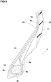
- Fig. 1 is a tire meridian sectional view including a tire rotational axis, of a pneumatic tire 1 as an embodiment of the present invention.
- the pneumatic tire 1 comprises a tread portion 2, a pair of axially spaced bead portions 4 each with a bead core 5 embedded therein, a pair of sidewall portions 3 extending between the tread edges and the bead portions 4, a carcass 6 extending between the bead portions 4, and a tread reinforcing belt 7 disposed radially outside the carcass 6 in the tread portion 2.
- various dimensions, positions and the like of the tire refer to those under such a condition that the tire is held, without being mounted on a wheel rim, so that the bead width between the bead portions becomes equal to the rim width between rim flanges of a wheel rim determined by the tire size, for example, according to standards organizations, i.e. JATMA, T&RA, ETRTO, TRAA, STRO, ALAPA, ITTAC and the like, or specified by the tire manufacturer.
- the region Y1 satisfying the conditions (1) and (2) is positioned on the larger outer diameter Dt side (namely, on the upper side in the graph) of the average relationship Ka expressed by the expression (A). In other word, the region Y1 is not overlapped with the average relationship Ka.
- the tire 1 satisfying the conditions (1) and (2) has a narrow tire section width and a large tire outer diameter Dt, and thereby, the rolling resistance and the air resistance are reduced. Thus, the tire 1 has excellent fuel consumption performance.
- a tire 1A having a relatively large outer diameter Dt has less bending deformation in the tire circumferential direction than a tire 1B having a relatively small outer diameter Dt, therefore, the amount of energy loss is small, which is effective in reducing the rolling resistance.
- the condition (2) is not satisfied, it becomes difficult to obtain the reduction of the rolling resistance by the large tire outer diameter.
- the condition (1) is not satisfied, in order to obtain a required load capacity, the tire needs to be inflated to a higher pressure, which adversely affects the ride comfort performance and the noise performance.
- the bead core 5 in this embodiment is formed in a rectangular shape having a radially outer surface 5a and an axially inner surface 5b extending radially inwardly from the axially inner end of the radially outer surface 5a.
- the bead core 5 is not limited to such a rectangular shape. It is possible to adopt various shapes such as a circular shape and a hexagonal shape.
- the carcass 6 extends between the bead portions 4 through the tread portion 2 and the sidewall portions 3.
- the carcass 6 in this example is composed of a single ply 6A of carcass cords arranged radially at an angle of from 75 to 90 degrees with respect to the tire equator C.
- the carcass ply 6A extends between the bead portions 4 through the tread portion 2 and the sidewall portions 3, and is turned up around the bead core 6 in each bead portion 4 from the inside to the outside of the tire so as to form a pair of turnup portions 6b and a main portion 6a therebetween.
- the turnup portion 6b extends radially outwardly along the axially outer surface of the bead core beyond the radially outer surface 5a, and then contacts with the main portion 6a.
- the belt 7 is composed of two cross breaker plies 7A and 7B of cords arranged at an angle of from 10 to 35 degrees with respect to the tire equator C for example.
- the belt 7 has edges 7e on both sides of the tire equator C, and the belt 7 extends continuously from one of the edges 7e to the other.
- Each of the bead portions 4 is provided with a first apex rubber 8A disposed between the main portion 6a and the turnup portion 6b, and a second apex rubber 8B disposed axially outside the turnup portion 6b.
- the first apex rubber 8A and second apex rubber 8B have different complex elastic moduli.
- the complex elastic modulus E*b of the second apex rubber 8B is higher than the complex elastic modulus E*a of the first apex rubber 8A.
- Such second apex rubber 8B contributes to enhancing the in-plane torsional rigidity of the bead portion 4 of the tire 1 having a narrow and large diameter, and improves the steering stability performance. Further, the first apex rubber 8A contributes to suppressing an increase in the vertical spring constant of the bead portion 4 of the tire 1 having a narrow width and large outer diameter, and thus improves the ride comfort performance and the noise performance.
- the complex elastic modulus E* is measured according to Japanese Industrial Standard (JIS) K6394, using a viscoelasticity spectrometer in the tensile deformation mode under the following conditions: initial strain of 10%, amplitude of +/-2%, frequency of 10 Hz, and temperature of 70 degrees C.
- JIS Japanese Industrial Standard
- the complex elastic modulus E*b of the second apex rubber 8B is set in a range from 60 to 70 MPa. If the complex elastic modulus E*b of the second apex rubber 8B is less than 60 MPa, then the in-plane torsional rigidity may not be increased. If the complex elastic modulus E*b of the second apex rubber 8B is more than 70 MPa, then the vertical spring constant of the bead portion 4 becomes large, which may deteriorate the ride comfort performance and the noise performance.
- the difference (E*b- E*a) between the complex elastic modulus E*b of the second apex rubber 8B and the complex elastic modulus E*a of the first apex rubber 8A is set in a range from 15 to 35 MPa. If the difference (E*b-E*a) is less than 15 MPa or more than 35 MPa, then it becomes difficult to improve the steering stability performance enjoying benefit of the increase of the in-plane torsional rigidity of the bead portion 4, and the noise performance and the ride comfort performance enjoying benefit of suppressing the increase of the vertical spring constant, in a well-balanced manner.
- the first apex rubber 8A extends radially outwardly from the radially outer surface 5a of the bead core 5.
- the first apex rubber 8A is tapered toward the radially outer edge thereof so as to have a triangular cross-sectional shape.
- the first apex rubber 8A is disposed to improve the steering stability performance by moderately reinforcing the bead portion while suppressing excessive reduction of the vertical spring constant.
- the second apex rubber 8B is disposed so as to abut on the axially outer side of the main portion 6a and the axially outer side of the turnup portion 6b. Such second apex rubber 8B prevents the main portion 6a and the turnup portion 6b from collapsing axially inward, thereby, the improved steering stability performance is maintained.
- the radially outer edge 11e of the second apex rubber 8B is located radially inside the maximum tire section width position M.
- Such second apex rubber 8B avoids an excessive increase in the in-plane torsional rigidity of the bead portion 4 and maintains the noise performance at high level.
- the second apex rubber 8B has a maximum thickness d2 which occurs in a range in the tire radial direction extending toward the radially inside and toward the radially outside from the radially outer edge 10e of the first apex rubber 8A by 10% of the radial dimension H1 of the first apex rubber 8A.
- the maximum thickness d2 of the second apex rubber 8B is set in a range from 2.0 to 4.0 mm in order to improve the ride comfort performance, the noise performance, and the steering stability performance in a well-balanced manner.
- the radially inner edge 11i of the second apex rubber 8B is located in a range in the tire radial direction extending 3 mm toward the radially inside and toward the radially outside from the radially outer surface 5a of the bead core 5. If the radially inner edge 11i of the second apex rubber 8B is located at a radial position more than 3 mm radially outward from the radially outer surface 5a, the effect of improving the in-plane torsional rigidity may be reduced.
- the in-plane torsional rigidity of the bead portion 4 cannot be increased as expected, despite an increase in the tire weight.
- the radial dimension H2 of the second apex rubber 8B is not less than 2.5 times, more preferably not less than 3.0 times, but not more than 4.0 times, more preferably not more than 3.5 times the radial dimension H1 of the first apex rubber 8A. If the radial dimension H2 of the second apex rubber 8B is less than 2.5 times the radial dimension H1 of the first apex rubber 8A, then the effect of suppressing the increase in the vertical spring constant may be excessively increased.
- the radial dimension H2 of the second apex rubber 8B is more than 4.0 times the radial dimension H1 of the first apex rubber 8A, then the in-plane torsional rigidity of the bead portion 4 may be excessively increased.
- the radial dimension H2 of the second apex rubber 8B is set in a range from 25 to 40 mm, for example.
- the bead portions 4 are each provided with a clinch rubber 13 disposed axially outside the second apex rubber 8B.
- the clinch rubber 13 has a complex elastic modulus E*2 which is lower than the complex elastic modulus E*b of the second apex rubber 8B in order to suppress an unnecessary increase in the vertical spring constant of the bead portion 4 and not to deteriorate the noise performance.
- the difference (E*b-E*2) between the complex elastic modulus E*2 of the clinch rubber 13 and the complex elastic modulus E*b of the second apex rubber 8B is set in a range from 15 to 30 MPa, for example.
- the clinch rubber 13 abuts on the axially outer side of the second apex rubber 8B, and forms a part of the outer surface 1a of the tire 1.
- the clinch rubber 13 prevents abrasion by a rim flange.
- the radially outer edge 13e of the clinch rubber 13 is located radially inside the radially outer edge 11e of the second apex rubber 8B.
- Such clinch rubber 13 enhances the in-plane torsional rigidity in a well-balanced manner while suppressing an increase in the vertical spring constant of the bead portion 4. It is preferable that the radial distance La between the radially outer edge 13e of the clinch rubber 13 and the radially outer edge 11e of the second apex rubber 8B is not less than 20%, but not more than 50% of the radial dimension H1 of the first apex rubber 8A.
- the radially inner edge 13i of the clinch rubber 13 is preferably extended to a position radially inside the bead core 5, more preferably extended to the base of the bead portion.
- the main portion 6a of the carcass 6 includes a first inclined portion 16 which is positioned radially inside the maximum tire section width position M, and is inclined at an angle ⁇ 1 in a range from 50 to 60 degrees with respect to the tire axial direction.
- the angle ⁇ 1 may be substantially constant, namely, the first inclined portion 16 may be substantially straight.
- the angle ⁇ 1 may be variable within the above range; for example, the first inclined portion 16 may be curved in an arc shape.
- Such first inclined portion 16 can effectively improve the steering stability performance during cornering.
- the first inclined portion 16 is substantially straight.
- Such first inclined portion 16 can maintain high ride comfort performance.
- the term "substantially straight” is meant to include an arc having a radius of curvature of more than 1000 mm in addition to straight.
- the first inclined portion 16 in this example has
- the radial dimension L3 of the first inclined portion 16 is smaller than the radial dimension H2 of the second apex rubber 8B. Further, the radial dimension L3 of the first inclined portion 16 is larger than the radial dimension H1 of the first apex rubber 8A. Such first inclined portion 16 can prevent the ride comfort performance from deteriorating.
- the radially outer end 16e of the first inclined portion 16 is preferably located radially inside the radially outer edge 11e of the second apex rubber 8B.
- the radially inner end 16i of the first inclined portion 16 is preferably located radially outside the radially outer surface 5a of the bead core 5.
- the radial dimension L3 of the first inclined portion 16 is preferably set in a range from 70% to 90% of the radial dimension H2 of the second apex rubber 8B.
- the main portion 6a of the carcass ply further includes a first arc-shaped portion 17 and a second arc-shaped portion 18.
- the first arc-shaped portion 17 extends radially outward continuously from the first inclined portion 16, and is curved convexly toward the axially outside.
- the second arc-shaped portion 18 extends radially inward continuously from the first inclined portion 16, and is curved convexly toward the axially inside.
- the first arc-shaped portion 17 and the second arc-shaped portion 18 are each defined as having a single radius of curvature of not more than 25 mm.
- the first arc-shaped portion 17 is located near the maximum tire section width position M.
- the first arc-shaped portion 17 in this example extends between the first inclined portion 16 and the maximum tire section width position M.
- the second arc-shaped portion 18 is provided adjacently to the corner 5c where the radially outer surface 5a and the axially inner surface 5b of the bead core 5 intersect.
- the second arc-shaped portion 18 extends toward the radially inside and toward the radially outside from the corner 5c.
- the radius R1 of curvature of the first arc-shaped portion 17 is smaller than the radius R2 of curvature of the second arc-shaped portion 18.
- Such first arc-shaped portion 17 serves to reduce the vertical spring constant of the sidewall portion 3 and enhance the ride comfort performance and the noise performance.
- the second arc-shaped portion 18 suppresses looseness of the carcass ply 6A and maintains the steering stability performance at high level.
- the radial height Ha of the maximum tire section width position M is set in a range from 40% to 60% of the cross-section height H of the tire 1, each measured from the bead base line BL.
- the cross-section height H corresponds to 1/2 of the difference between the tire outer diameter Dt and the rim diameter (not shown).
- pneumatic tires of size 175/60R18 for passenger cars were experimentally manufactured and tested for the steering stability performance, noise performance, and ride comfort performance as follows.
- test tires mounted on wheel rims of size 18x5.0J and inflated to 260 KPa were attached to a 1800cc passenger car.
- the test driver evaluated the ride comfort performance, and the steering stability performance based on responsiveness, rigidity, gripping force, stability, and transient characteristics.
- the results of the steering stability performance and the ride comfort performance are indicated in Table 1 by an index based on Comparative example tire Ref.1 being 100, wherein the larger value is better.
- the noise performance test was conducted by measuring the sound pressure level of a 100-350 Hz frequency band in the interior of the running vehicle.
- the results of the noise performance are indicated in Table 1 by an index based on the sound pressure level (dB) of Comparative example tire Ref.1 being 100, wherein the smaller value is better.
- the example tires according to the present invention was improved in the steering stability performance, the noise performance and the ride comfort performance in a well balanced manner.
Landscapes
- Engineering & Computer Science (AREA)
- Mechanical Engineering (AREA)
- Tires In General (AREA)
Abstract
Description
- The present invention relates to a pneumatic tire.
- In recent years, pneumatic tires are required to contribute to improvement of fuel efficiency.
- Patent Document 1 below discloses a pneumatic tire which has a narrow width and a large outer diameter in order to reduce the rolling resistance and air resistance. Hereinafter, such a pneumatic tire is referred as "narrow-with large-diameter pneumatic tire".
Patent Document 1: Japanese Patent Application Publication No.2015-33984 - A narrow-with large-diameter pneumatic tire is usually inflated to a relatively high pressure, therefore, the vertical spring constant of the tire is increased.
This tends to degrade the ride comfort performance and noise (road noise) performance of the tire. Thus, the narrow-with large-diameter pneumatic tire has room for improvement in this regard. - In order to avoid such increase in the vertical spring constant, it is conceivable to reduce the size of a bead apex rubber which is disposed in the bead portion to reinforce the bead portion. Such a technique is however, liable to decrease the in-plane torsional rigidity of the bead portion, which leads to deterioration in the steering stability performance of the tire.
- In view of the above-described problems, the present invention was made, and a primary objective of the present invention is to provide a narrow-with large-diameter pneumatic tire in which the ride comfort performance, noise performance, and steering stability performance can be improved in a well-balanced manner.
- According to the present invention, a pneumatic tire comprises:
- a tread portion,
- a pair of sidewall portions,
- a pair of bead portions each with a bead core embedded therein,
- a carcass ply extending between the bead portions through the tread portion and the sidewall portions, and turned up around the bead core in each of the bead portions from the inside to the outside of the tire so as to form a pair of turnup portions and a main portion therebetween, and
- a first apex rubber and a second apex rubber disposed in each of the bead portions,
wherein - the first apex rubber is disposed between the above-said turnup portion and main portion,
- the second apex rubber is disposed axially outside the turnup portion, and
- a complex elastic modulus E*b of the second apex rubber is larger than a complex elastic modulus E*a of the first apex rubber,
wherein - a cross-sectional width wt in mm of the tire and an outer diameter Dt in mm of the tire satisfy the following conditions (1) and (2),


- It is preferable that the difference (E*b-E*a) between the complex elastic modulus E*b of the second apex rubber and the complex elastic modulus E*a of the first apex rubber is in a range from 15 to 35 MPa.
- It is preferable that the complex elastic modulus E*b of the second apex rubber is in a range from 60 to 70 MPa.
- It is preferable that the second apex rubber has a radially outer edge located radially inside the maximum tire section width position.
- It is preferable that the bead portions are each provided with a clinch rubber located axially outside the second apex rubber, and
the clinch rubber has a radially outer edge located radially inside the radially outer edge of the second apex rubber. - It is preferable that the second apex rubber has a maximum thickness at a radial position within a range extending in the tire radial direction by a radial distance of 10% of a radial dimension of the first apex rubber, toward the radially outside and toward the radially inside from the radially outer edge of the first apex rubber.
- It is preferable that the radially inner edge of the second apex rubber is located within a range extending in the tire radial direction by a radial distance of 3 mm toward the radially outside and toward the radially inside from the outer surface of the bead core.
- It is preferable that a radial dimension of the second apex rubber is larger than a radial dimension of the first apex rubber.
- It is preferable that the radial dimension of the second apex rubber is in a range from 2.5 to 4.0 times the radial dimension of the first apex rubber.
- The present invention is based on a narrow-with large-diameter pneumatic tire whose cross-sectional width wt in mm and outer diameter Dt in mm satisfy conditions:
(1): Dt =< 59.078 x Wt0.498 and (2): Dt >= 59.078 x wt0.460 According to the present invention, the second apex rubber having the complex elastic modulus higher than that of the first apex rubber can increase the in-plane torsional rigidity of the bead portion, and improve the steering stability.
At the same time, the first apex rubber can moderate the radial stiffness of the bead portion, and improves the ride comfort performance and noise performance.
Therefore, the narrow-with large-diameter pneumatic tire according to the present invention is improved in the ride comfort performance, noise performance, and steering stability performance in a well-balanced manner. -
-
Fig. 1 is a cross-sectional view of a pneumatic tire as an embodiment of the present invention. -
Fig. 2 is a graph in which cross-sectional width values and outer diameter values of conventional pneumatic tires which values are regulated by the Japan Automobile Tire Manufacturers Association, are plotted. -
Fig. 3 is a conceptual diagram illustrating the effect of increasing the diameter of a pneumatic tire. -
Figs. 4 ,5 and6 are enlarged cross sectional views of the bead portion shown inFig. 1 which are the same but differently provided with reference numbers. - The present invention can be applied to pneumatic tires for heavy duty vehicles such as trucks and buses, but suitably applied to pneumatic tires for passenger cars.
- Taking a pneumatic tires for passenger cars as example, an embodiments of the present invention will now be described in detail in conjunction with accompanying drawings.
-
Fig. 1 is a tire meridian sectional view including a tire rotational axis, of a pneumatic tire 1 as an embodiment of the present invention. - The pneumatic tire 1 comprises a
tread portion 2, a pair of axially spacedbead portions 4 each with abead core 5 embedded therein, a pair ofsidewall portions 3 extending between the tread edges and thebead portions 4, acarcass 6 extending between thebead portions 4, and atread reinforcing belt 7 disposed radially outside thecarcass 6 in thetread portion 2. - In this specification, unless otherwise noted, various dimensions, positions and the like of the tire refer to those under such a condition that the tire is held, without being mounted on a wheel rim, so that the bead width between the bead portions becomes equal to the rim width between rim flanges of a wheel rim determined by the tire size, for example, according to standards organizations, i.e. JATMA, T&RA, ETRTO, TRAA, STRO, ALAPA, ITTAC and the like, or specified by the tire manufacturer.
- According to the present invention, the tire 1 satisfies the following conditions (1) and (2),


- Dt is the outer diameter in mm of the tire measured at the tire equator C, and
- wt is the cross-section width in mm of the tire measured at the maximum tire section width position M.
-
Fig. 2 is a graph obtained by plotting results of an investigation of the relationship between the cross-sectional width wt and the tire outer diameter Dt represented by JATMA which was carried out on conventional tires.
From the results, the average relationship between the tire cross-sectional width wt and the tire outer diameter Dt in the conventional tires represented by JATMA can be expressed by the following expression (A) as indicated by an envelope curve Ka inFig. 2 :
- On the other hand, the region Y1 satisfying the conditions (1) and (2) is positioned on the larger outer diameter Dt side (namely, on the upper side in the graph) of the average relationship Ka expressed by the expression (A). In other word, the region Y1 is not overlapped with the average relationship Ka.
The tire 1 satisfying the conditions (1) and (2) has a narrow tire section width and a large tire outer diameter Dt, and thereby, the rolling resistance and the air resistance are reduced. Thus, the tire 1 has excellent fuel consumption performance. - As schematically shown in
Fig. 3 , in the tire ground contacting patch, atire 1A having a relatively large outer diameter Dt has less bending deformation in the tire circumferential direction than atire 1B having a relatively small outer diameter Dt, therefore, the amount of energy loss is small, which is effective in reducing the rolling resistance. when the condition (2) is not satisfied, it becomes difficult to obtain the reduction of the rolling resistance by the large tire outer diameter.
when the condition (1) is not satisfied, in order to obtain a required load capacity, the tire needs to be inflated to a higher pressure, which adversely affects the ride comfort performance and the noise performance. - The
bead core 5 in this embodiment is formed in a rectangular shape having a radiallyouter surface 5a and an axiallyinner surface 5b extending radially inwardly from the axially inner end of the radiallyouter surface 5a. Thebead core 5 is not limited to such a rectangular shape. It is possible to adopt various shapes such as a circular shape and a hexagonal shape. - The
carcass 6 extends between thebead portions 4 through thetread portion 2 and thesidewall portions 3. - The
carcass 6 in this example is composed of asingle ply 6A of carcass cords arranged radially at an angle of from 75 to 90 degrees with respect to the tire equator C. The carcass ply 6A extends between thebead portions 4 through thetread portion 2 and thesidewall portions 3, and is turned up around thebead core 6 in eachbead portion 4 from the inside to the outside of the tire so as to form a pair ofturnup portions 6b and amain portion 6a therebetween. Theturnup portion 6b extends radially outwardly along the axially outer surface of the bead core beyond the radiallyouter surface 5a, and then contacts with themain portion 6a. - The
belt 7 is composed of two cross breaker plies 7A and 7B of cords arranged at an angle of from 10 to 35 degrees with respect to the tire equator C for example.
Thebelt 7 hasedges 7e on both sides of the tire equator C, and thebelt 7 extends continuously from one of theedges 7e to the other. - Each of the
bead portions 4 is provided with a firstapex rubber 8A disposed between themain portion 6a and theturnup portion 6b, and a secondapex rubber 8B disposed axially outside theturnup portion 6b.
The firstapex rubber 8A and secondapex rubber 8B have different complex elastic moduli. The complex elastic modulus E*b of the secondapex rubber 8B is higher than the complex elastic modulus E*a of the firstapex rubber 8A. - Such second
apex rubber 8B contributes to enhancing the in-plane torsional rigidity of thebead portion 4 of the tire 1 having a narrow and large diameter, and improves the steering stability performance.
Further, the firstapex rubber 8A contributes to suppressing an increase in the vertical spring constant of thebead portion 4 of the tire 1 having a narrow width and large outer diameter, and thus improves the ride comfort performance and the noise performance. - Here, the complex elastic modulus E* is measured according to Japanese Industrial Standard (JIS) K6394, using a viscoelasticity spectrometer in the tensile deformation mode under the following conditions: initial strain of 10%, amplitude of +/-2%, frequency of 10 Hz, and temperature of 70 degrees C.
- It is preferable that the complex elastic modulus E*b of the second
apex rubber 8B is set in a range from 60 to 70 MPa. If the complex elastic modulus E*b of the secondapex rubber 8B is less than 60 MPa, then the in-plane torsional rigidity may not be increased.
If the complex elastic modulus E*b of the secondapex rubber 8B is more than 70 MPa, then the vertical spring constant of thebead portion 4 becomes large, which may deteriorate the ride comfort performance and the noise performance. - Preferably, the difference (E*b- E*a) between the complex elastic modulus E*b of the second
apex rubber 8B and the complex elastic modulus E*a of the firstapex rubber 8A is set in a range from 15 to 35 MPa.
If the difference (E*b-E*a) is less than 15 MPa or more than 35 MPa, then it becomes difficult to improve
the steering stability performance enjoying benefit of the increase of the in-plane torsional rigidity of thebead portion 4, and the noise performance and the ride comfort performance enjoying benefit of suppressing the increase of the vertical spring constant, in a well-balanced manner. - The first
apex rubber 8A extends radially outwardly from the radiallyouter surface 5a of thebead core 5. The firstapex rubber 8A is tapered toward the radially outer edge thereof so as to have a triangular cross-sectional shape. The firstapex rubber 8A is disposed to improve the steering stability performance by moderately reinforcing the bead portion while suppressing excessive reduction of the vertical spring constant. - The second
apex rubber 8B is disposed so as to abut on the axially outer side of themain portion 6a and the axially outer side of theturnup portion 6b.
Such secondapex rubber 8B prevents themain portion 6a and theturnup portion 6b from collapsing axially inward, thereby, the improved steering stability performance is maintained. - The radially
outer edge 11e of the secondapex rubber 8B is located radially inside the maximum tire section width position M.
Such secondapex rubber 8B avoids an excessive increase in the in-plane torsional rigidity of thebead portion 4 and maintains the noise performance at high level. - The second
apex rubber 8B has a maximum thickness d2 which occurs in a range in the tire radial direction extending toward the radially inside and toward the radially outside from the radiallyouter edge 10e of the firstapex rubber 8A by 10% of the radial dimension H1 of the firstapex rubber 8A. Thereby, the vicinity of the radiallyouter edge 10e where the reinforcing effect of the firstapex rubber 8A becomes minimum, is reinforced, and the above-mentioned axially inward collapsing of themain portion 6a and theturnup portion 6b can be effectively prevented. - It is preferable that the maximum thickness d2 of the second
apex rubber 8B is set in a range from 2.0 to 4.0 mm in order to improve the ride comfort performance, the noise performance, and the steering stability performance in a well-balanced manner. - It is preferable that the radially
inner edge 11i of the secondapex rubber 8B is located in a range in the tire radial direction extending 3 mm toward the radially inside and toward the radially outside from the radiallyouter surface 5a of thebead core 5.
If the radiallyinner edge 11i of the secondapex rubber 8B is located at a radial position more than 3 mm radially outward from the radiallyouter surface 5a, the effect of improving the in-plane torsional rigidity may be reduced.
If the radiallyinner edge 11i of the secondapex rubber 8B is located at a radial position more than 3 mm radially inward from the radiallyouter surface 5a, the in-plane torsional rigidity of thebead portion 4 cannot be increased as expected, despite an increase in the tire weight. - It is preferable that the radial dimension H2 of the second
apex rubber 8B is not less than 2.5 times, more preferably not less than 3.0 times, but not more than 4.0 times, more preferably not more than 3.5 times the radial dimension H1 of the firstapex rubber 8A.
If the radial dimension H2 of the secondapex rubber 8B is less than 2.5 times the radial dimension H1 of the firstapex rubber 8A, then the effect of suppressing the increase in the vertical spring constant may be excessively increased.
If the radial dimension H2 of the secondapex rubber 8B is more than 4.0 times the radial dimension H1 of the firstapex rubber 8A, then the in-plane torsional rigidity of thebead portion 4 may be excessively increased.
Preferably, the radial dimension H2 of the secondapex rubber 8B is set in a range from 25 to 40 mm, for example. - The
bead portions 4 are each provided with aclinch rubber 13 disposed axially outside the secondapex rubber 8B. - Preferably, the
clinch rubber 13 has a complex elastic modulus E*2 which is lower than the complex elastic modulus E*b of the secondapex rubber 8B in order to suppress an unnecessary increase in the vertical spring constant of thebead portion 4 and not to deteriorate the noise performance.
Preferably, the difference (E*b-E*2) between the complex elastic modulus E*2 of theclinch rubber 13 and the complex elastic modulus E*b of the secondapex rubber 8B is set in a range from 15 to 30 MPa, for example. - In this embodiment, the
clinch rubber 13 abuts on the axially outer side of the secondapex rubber 8B, and forms a part of theouter surface 1a of the tire 1. Theclinch rubber 13 prevents abrasion by a rim flange. - The radially
outer edge 13e of theclinch rubber 13 is located radially inside the radiallyouter edge 11e of the secondapex rubber 8B.
Such clinch rubber 13 enhances the in-plane torsional rigidity in a well-balanced manner while suppressing an increase in the vertical spring constant of thebead portion 4. It is preferable that the radial distance La between the radiallyouter edge 13e of theclinch rubber 13 and the radiallyouter edge 11e of the secondapex rubber 8B is not less than 20%, but not more than 50% of the radial dimension H1 of the firstapex rubber 8A. - The radially
inner edge 13i of theclinch rubber 13 is preferably extended to a position radially inside thebead core 5, more preferably extended to the base of the bead portion. - As shown in
Fig. 5 , in the cross sectional view of the bead portion, themain portion 6a of thecarcass 6 includes a firstinclined portion 16 which is positioned radially inside the maximum tire section width position M, and is inclined at an angle θ1 in a range from 50 to 60 degrees with respect to the tire axial direction.
The angle θ1 may be substantially constant, namely, the firstinclined portion 16 may be substantially straight. Alternatively, the angle θ1 may be variable within the above range; for example, the firstinclined portion 16 may be curved in an arc shape.
Such firstinclined portion 16 can effectively improve the steering stability performance during cornering. In the present embodiment, the firstinclined portion 16 is substantially straight. Such firstinclined portion 16 can maintain high ride comfort performance. In this specification, the term "substantially straight" is meant to include an arc having a radius of curvature of more than 1000 mm in addition to straight. - The first
inclined portion 16 in this example has - a
first portion 16a abutting to the axially inner side of the firstapex rubber 8A, and - a
second portion 16b abutting to the axially inner side of the secondapex rubber 8B. - The radial dimension L3 of the first
inclined portion 16 is smaller than the radial dimension H2 of the secondapex rubber 8B. Further, the radial dimension L3 of the firstinclined portion 16 is larger than the radial dimension H1 of the firstapex rubber 8A. Such firstinclined portion 16 can prevent the ride comfort performance from deteriorating. - In order to effectively derive the above mentioned advantageous effect, the radially
outer end 16e of the firstinclined portion 16 is preferably located radially inside the radiallyouter edge 11e of the secondapex rubber 8B. The radiallyinner end 16i of the firstinclined portion 16 is preferably located radially outside the radiallyouter surface 5a of thebead core 5.
Further, the radial dimension L3 of the firstinclined portion 16 is preferably set in a range from 70% to 90% of the radial dimension H2 of the secondapex rubber 8B. - As shown in
Fig. 6 , in the cross sectional view of the bead portion, themain portion 6a of the carcass ply further includes a first arc-shapedportion 17 and a second arc-shapedportion 18. - The first arc-shaped
portion 17 extends radially outward continuously from the firstinclined portion 16, and is curved convexly toward the axially outside.
The second arc-shapedportion 18 extends radially inward continuously from the firstinclined portion 16, and is curved convexly toward the axially inside.
The first arc-shapedportion 17 and the second arc-shapedportion 18 are each defined as having a single radius of curvature of not more than 25 mm. - In the present embodiment, the first arc-shaped
portion 17 is located near the maximum tire section width position M. The first arc-shapedportion 17 in this example extends between the firstinclined portion 16 and the maximum tire section width position M. - In the present embodiment, the second arc-shaped
portion 18 is provided adjacently to thecorner 5c where the radiallyouter surface 5a and the axiallyinner surface 5b of thebead core 5 intersect. The second arc-shapedportion 18 extends toward the radially inside and toward the radially outside from thecorner 5c. - In the present embodiment, the radius R1 of curvature of the first arc-shaped
portion 17 is smaller than the radius R2 of curvature of the second arc-shapedportion 18.
Such first arc-shapedportion 17 serves to reduce the vertical spring constant of thesidewall portion 3 and enhance the ride comfort performance and the noise performance.
Further, the second arc-shapedportion 18 suppresses looseness of thecarcass ply 6A and maintains the steering stability performance at high level. - In order to improve the ride comfort performance, noise performance, and steering stability performance of this narrow-with large-diameter pneumatic tire 1 in a well-balanced manner, it is preferred that the radial height Ha of the maximum tire section width position M is set in a range from 40% to 60% of the cross-section height H of the tire 1, each measured from the bead base line BL. Incidentally, the cross-section height H corresponds to 1/2 of the difference between the tire outer diameter Dt and the rim diameter (not shown).
- while detailed description has been made of a preferable embodiment of the present invention, the present invention can be embodied in various forms without being limited to the illustrated embodiment.
- Based on the structure shown in
Fig. 1 , pneumatic tires of size 175/60R18 for passenger cars were experimentally manufactured and tested for the steering stability performance, noise performance, and ride comfort performance as follows. - Specifications of the test tires are listed in Table 1.
- The test tires mounted on wheel rims of size 18x5.0J and inflated to 260 KPa were attached to a 1800cc passenger car. During running at 40 to 120 km/hr on a dry asphalt road of a test circuit course, the test driver evaluated the ride comfort performance, and the steering stability performance based on responsiveness, rigidity, gripping force, stability, and transient characteristics.
The results of the steering stability performance and the ride comfort performance are indicated in Table 1 by an index based on Comparative example tire Ref.1 being 100, wherein the larger value is better. - Further, the noise performance test was conducted by measuring the sound pressure level of a 100-350 Hz frequency band in the interior of the running vehicle.
The results of the noise performance are indicated in Table 1 by an index based on the sound pressure level (dB) of Comparative example tire Ref.1 being 100, wherein the smaller value is better.TABLE 1 Tier Ref.1 Ref.2 Ex.1 Ex.2 Ex.3 Ex.4 Ex.5 Ex.6 Ex.7 Ex.8 E*a (MPa) 65 30 30 30 50 30 55 30 30 30 E*b (MPa) 65 30 65 45 65 40 65 65 65 65 H2/ H1 3 3 3 3 3 3 3 4 3 3 d2 (mm) 3 3 3 3 3 3 3 3 5 3 H2 (mm) 30 30 30 30 30 30 30 30 30 45 Steering stability 100 80 102 100 102 100 102 102 102 105 Noise performance 100 90 90 90 92 92 94 90 92 95 Ride comfort 100 110 112 112 110 106 106 112 108 106 - From the test results, it was confirmed that, as compared with the comparative example tires, the example tires according to the present invention was improved in the steering stability performance, the noise performance and the ride comfort performance in a well balanced manner.
-
- 1
- pneumatic tire
- 4
- bead portion
- 5
- bead core
- 6
- carcass
- 6A
- carcass ply
- 6a
- main portion
- 6b
- turnup portion
- 8A
- first apex rubber
- 8B
- second apex rubber
Claims (9)
- A pneumatic tire comprising:a tread portion,a pair of sidewall portions,a pair of bead portions each with a bead core embedded therein,a carcass ply extending between the bead portions through the tread portion and the sidewall portions, and turned up around the bead core from the inside to the outside of the tire in each of the bead portions, so as to form a pair of turnup portions and a main portion therebetween, anda first apex rubber and a second apex rubber disposed in each of the bead portions,
whereinthe first apex rubber is disposed between the turnup portion and the main portion,the second apex rubber is disposed axially outside the turnup portion, anda complex elastic modulus E*b of the second apex rubber is larger than a complex elastic modulus E*a of the first apex rubber,
whereina cross-sectional width Wt in mm of the tire and an outer diameter Dt in mm of the tire satisfy the following conditions (1) and (2),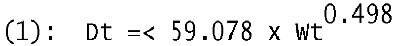

- The pneumatic tire according to claim 1, wherein
the difference (E*b-E*a) between the complex elastic modulus E*b of the second apex rubber and the complex elastic modulus E*a of the first apex rubber is in a range from 15 to 35 MPa. - The pneumatic tire according to claim 1 or 2, wherein
the complex elastic modulus E*b of the second apex rubber is in a range from 60 to 70 MPa. - The pneumatic tire according to any one of claims 1 to 3, wherein
the second apex rubber has a radially outer edge located radially inside a maximum tire section width position. - The pneumatic tire according to any one of claims 1 to 4, wherein
the bead portions are each provided with a clinch rubber located axially outside the second apex rubber, and the clinch rubber has a radially outer edge located radially inside the radially outer edge of the second apex rubber. - The pneumatic tire according to any one of claims 1 to 5, wherein
the second apex rubber has a maximum thickness at a radial position within a range extending in the tire radial direction by a radial distance of 10% of a radial dimension of the first apex rubber, toward the radially outside and toward the radially inside from the radially outer edge of the first apex rubber. - The pneumatic tire according to any one of claims 1 to 7, wherein
the radially inner edge of the second apex rubber is located within a range
extending in the tire radial direction by a radial distance of 3 mm toward the radially outside from the outer surface of the bead core, and
extending in the tire radial direction by a radial distance of 3 mm toward the radially inside from the outer surface of the bead core. - The pneumatic tire according to any one of claims 1 to 7, wherein
a radial dimension of the second apex rubber is larger than a radial dimension of the first apex rubber. - The pneumatic tire according to claim 8, wherein
the radial dimension of the second apex rubber is in a range from 2.5 to 4.0 times the radial dimension of the first apex rubber.
Applications Claiming Priority (1)
| Application Number | Priority Date | Filing Date | Title |
|---|---|---|---|
| JP2019176012A JP7380014B2 (en) | 2019-09-26 | 2019-09-26 | pneumatic tires |
Publications (2)
| Publication Number | Publication Date |
|---|---|
| EP3798019A1 true EP3798019A1 (en) | 2021-03-31 |
| EP3798019B1 EP3798019B1 (en) | 2022-02-23 |
Family
ID=72240349
Family Applications (1)
| Application Number | Title | Priority Date | Filing Date |
|---|---|---|---|
| EP20192614.4A Active EP3798019B1 (en) | 2019-09-26 | 2020-08-25 | Pneumatic tire |
Country Status (4)
| Country | Link |
|---|---|
| US (1) | US11453241B2 (en) |
| EP (1) | EP3798019B1 (en) |
| JP (1) | JP7380014B2 (en) |
| CN (1) | CN112549866A (en) |
Cited By (1)
| Publication number | Priority date | Publication date | Assignee | Title |
|---|---|---|---|---|
| EP4368417A1 (en) * | 2022-11-11 | 2024-05-15 | The Goodyear Tire & Rubber Company | Pneumatic radial tire |
Families Citing this family (2)
| Publication number | Priority date | Publication date | Assignee | Title |
|---|---|---|---|---|
| JP2022100978A (en) * | 2020-12-24 | 2022-07-06 | 住友ゴム工業株式会社 | Pneumatic tire |
| KR102670576B1 (en) * | 2021-11-09 | 2024-05-29 | 금호타이어 주식회사 | Pneumatic tire |
Citations (5)
| Publication number | Priority date | Publication date | Assignee | Title |
|---|---|---|---|---|
| GB2092964A (en) * | 1981-02-12 | 1982-08-25 | Michelin & Cie | A pneumatic tyre |
| JP2015033984A (en) | 2013-08-09 | 2015-02-19 | 住友ゴム工業株式会社 | Pneumatic tire |
| JP2016078564A (en) * | 2014-10-15 | 2016-05-16 | 住友ゴム工業株式会社 | tire |
| DE112016002176T5 (en) * | 2015-05-14 | 2018-01-25 | The Yokohama Rubber Co., Ltd. | tire |
| EP3315327A1 (en) * | 2016-10-26 | 2018-05-02 | Sumitomo Rubber Industries, Ltd. | Pneumatic tire |
Family Cites Families (18)
| Publication number | Priority date | Publication date | Assignee | Title |
|---|---|---|---|---|
| US5772811A (en) * | 1995-06-19 | 1998-06-30 | Sumitomo Rubber Industries, Ltd. | Heavy duty radial tire with specified bead core inside diameter |
| JP4643817B2 (en) * | 2000-11-27 | 2011-03-02 | 住友ゴム工業株式会社 | Pneumatic tire |
| DE60210191T2 (en) * | 2001-11-08 | 2006-11-09 | Sumitomo Rubber Industries Ltd., Kobe | Pneumatic radial tire |
| JP4276470B2 (en) * | 2003-05-27 | 2009-06-10 | 住友ゴム工業株式会社 | Pneumatic tire |
| JP4621091B2 (en) * | 2005-08-10 | 2011-01-26 | 住友ゴム工業株式会社 | Pneumatic tire |
| JP4681497B2 (en) * | 2006-05-08 | 2011-05-11 | 住友ゴム工業株式会社 | Pneumatic tire |
| FR2940189B1 (en) * | 2008-12-22 | 2010-12-24 | Michelin Soc Tech | PNEUMATIC HAVING PERFECTED BOURRELETS |
| JP2012106531A (en) * | 2010-11-15 | 2012-06-07 | Sumitomo Rubber Ind Ltd | Tire for heavy load |
| JP5640057B2 (en) * | 2012-09-24 | 2014-12-10 | 住友ゴム工業株式会社 | Pneumatic tire |
| JP2015030428A (en) * | 2013-08-06 | 2015-02-16 | 住友ゴム工業株式会社 | Pneumatic tire |
| US10513154B2 (en) * | 2014-02-26 | 2019-12-24 | Sumitomo Rubber Industries, Ltd. | Pneumatic tire with specified bead portions |
| JP6141243B2 (en) | 2014-09-04 | 2017-06-07 | 住友ゴム工業株式会社 | Pneumatic tire |
| JP6141245B2 (en) | 2014-09-29 | 2017-06-07 | 住友ゴム工業株式会社 | Pneumatic tire |
| US10759233B2 (en) * | 2014-09-04 | 2020-09-01 | Sumitomo Rubber Industries, Ltd. | Pneumatic tire |
| JP6457821B2 (en) | 2015-01-14 | 2019-01-23 | 住友ゴム工業株式会社 | Pneumatic tire |
| JP6540343B2 (en) * | 2015-08-04 | 2019-07-10 | 住友ゴム工業株式会社 | Pneumatic tire |
| JP6815102B2 (en) * | 2016-06-09 | 2021-01-20 | 株式会社ブリヂストン | tire |
| JP6790845B2 (en) * | 2017-01-13 | 2020-11-25 | 住友ゴム工業株式会社 | Pneumatic tires for heavy loads |
-
2019
- 2019-09-26 JP JP2019176012A patent/JP7380014B2/en active Active
-
2020
- 2020-08-07 CN CN202010787831.3A patent/CN112549866A/en active Pending
- 2020-08-25 EP EP20192614.4A patent/EP3798019B1/en active Active
- 2020-09-11 US US17/018,252 patent/US11453241B2/en active Active
Patent Citations (5)
| Publication number | Priority date | Publication date | Assignee | Title |
|---|---|---|---|---|
| GB2092964A (en) * | 1981-02-12 | 1982-08-25 | Michelin & Cie | A pneumatic tyre |
| JP2015033984A (en) | 2013-08-09 | 2015-02-19 | 住友ゴム工業株式会社 | Pneumatic tire |
| JP2016078564A (en) * | 2014-10-15 | 2016-05-16 | 住友ゴム工業株式会社 | tire |
| DE112016002176T5 (en) * | 2015-05-14 | 2018-01-25 | The Yokohama Rubber Co., Ltd. | tire |
| EP3315327A1 (en) * | 2016-10-26 | 2018-05-02 | Sumitomo Rubber Industries, Ltd. | Pneumatic tire |
Cited By (1)
| Publication number | Priority date | Publication date | Assignee | Title |
|---|---|---|---|---|
| EP4368417A1 (en) * | 2022-11-11 | 2024-05-15 | The Goodyear Tire & Rubber Company | Pneumatic radial tire |
Also Published As
| Publication number | Publication date |
|---|---|
| CN112549866A (en) | 2021-03-26 |
| EP3798019B1 (en) | 2022-02-23 |
| JP2021049959A (en) | 2021-04-01 |
| US20210094351A1 (en) | 2021-04-01 |
| JP7380014B2 (en) | 2023-11-15 |
| US11453241B2 (en) | 2022-09-27 |
Similar Documents
| Publication | Publication Date | Title |
|---|---|---|
| EP3798019A1 (en) | Pneumatic tire | |
| EP2113398B1 (en) | Pneumatic radial tire | |
| KR101320742B1 (en) | Heavy duty tire | |
| EP2017094B1 (en) | Pneumatic tire | |
| JP5038624B2 (en) | Run flat tire | |
| WO2012176476A1 (en) | Pneumatic radial tire for passenger car, method for using tire, and tire/rim assembly with tire | |
| EP1361076B1 (en) | Pneumatic tire | |
| EP3064376B1 (en) | Tire | |
| EP1083064A2 (en) | Pneumatic tires | |
| EP2275285B1 (en) | Pneumatic tire | |
| EP3967517B1 (en) | Heavy duty pneumatic tire | |
| JP4436146B2 (en) | Passenger car tires | |
| JP4915069B2 (en) | Pneumatic tire | |
| EP3059100B1 (en) | Pneumatic tire | |
| EP3785935B1 (en) | Pneumatic tire | |
| JP4044367B2 (en) | Heavy duty pneumatic tire | |
| EP3936352B1 (en) | Pneumatic tire | |
| EP3878667B1 (en) | Pneumatic tire | |
| US5388626A (en) | Radial tire | |
| JP2021059231A (en) | Pneumatic tire | |
| EP3895916B1 (en) | Pneumatic tire | |
| EP4424527A1 (en) | Pneumatic tire | |
| EP4227114A1 (en) | Heavy duty tire | |
| JP4287709B2 (en) | Pneumatic tire | |
| JP7447510B2 (en) | pneumatic tires |
Legal Events
| Date | Code | Title | Description |
|---|---|---|---|
| PUAI | Public reference made under article 153(3) epc to a published international application that has entered the european phase |
Free format text: ORIGINAL CODE: 0009012 |
|
| STAA | Information on the status of an ep patent application or granted ep patent |
Free format text: STATUS: THE APPLICATION HAS BEEN PUBLISHED |
|
| AK | Designated contracting states |
Kind code of ref document: A1 Designated state(s): AL AT BE BG CH CY CZ DE DK EE ES FI FR GB GR HR HU IE IS IT LI LT LU LV MC MK MT NL NO PL PT RO RS SE SI SK SM TR |
|
| AX | Request for extension of the european patent |
Extension state: BA ME |
|
| STAA | Information on the status of an ep patent application or granted ep patent |
Free format text: STATUS: REQUEST FOR EXAMINATION WAS MADE |
|
| 17P | Request for examination filed |
Effective date: 20210629 |
|
| RBV | Designated contracting states (corrected) |
Designated state(s): AL AT BE BG CH CY CZ DE DK EE ES FI FR GB GR HR HU IE IS IT LI LT LU LV MC MK MT NL NO PL PT RO RS SE SI SK SM TR |
|
| GRAP | Despatch of communication of intention to grant a patent |
Free format text: ORIGINAL CODE: EPIDOSNIGR1 |
|
| STAA | Information on the status of an ep patent application or granted ep patent |
Free format text: STATUS: GRANT OF PATENT IS INTENDED |
|
| RIC1 | Information provided on ipc code assigned before grant |
Ipc: B60C 15/06 20060101ALI20211012BHEP Ipc: B60C 15/00 20060101ALI20211012BHEP Ipc: B60C 3/04 20060101AFI20211012BHEP |
|
| INTG | Intention to grant announced |
Effective date: 20211104 |
|
| RIN1 | Information on inventor provided before grant (corrected) |
Inventor name: NISHIJIMA, SHIGEKI |
|
| GRAS | Grant fee paid |
Free format text: ORIGINAL CODE: EPIDOSNIGR3 |
|
| GRAA | (expected) grant |
Free format text: ORIGINAL CODE: 0009210 |
|
| STAA | Information on the status of an ep patent application or granted ep patent |
Free format text: STATUS: THE PATENT HAS BEEN GRANTED |
|
| AK | Designated contracting states |
Kind code of ref document: B1 Designated state(s): AL AT BE BG CH CY CZ DE DK EE ES FI FR GB GR HR HU IE IS IT LI LT LU LV MC MK MT NL NO PL PT RO RS SE SI SK SM TR |
|
| REG | Reference to a national code |
Ref country code: GB Ref legal event code: FG4D |
|
| REG | Reference to a national code |
Ref country code: CH Ref legal event code: EP |
|
| REG | Reference to a national code |
Ref country code: DE Ref legal event code: R096 Ref document number: 602020001956 Country of ref document: DE |
|
| REG | Reference to a national code |
Ref country code: AT Ref legal event code: REF Ref document number: 1470170 Country of ref document: AT Kind code of ref document: T Effective date: 20220315 |
|
| REG | Reference to a national code |
Ref country code: IE Ref legal event code: FG4D |
|
| REG | Reference to a national code |
Ref country code: LT Ref legal event code: MG9D |
|
| REG | Reference to a national code |
Ref country code: NL Ref legal event code: MP Effective date: 20220223 |
|
| REG | Reference to a national code |
Ref country code: AT Ref legal event code: MK05 Ref document number: 1470170 Country of ref document: AT Kind code of ref document: T Effective date: 20220223 |
|
| PG25 | Lapsed in a contracting state [announced via postgrant information from national office to epo] |
Ref country code: SE Free format text: LAPSE BECAUSE OF FAILURE TO SUBMIT A TRANSLATION OF THE DESCRIPTION OR TO PAY THE FEE WITHIN THE PRESCRIBED TIME-LIMIT Effective date: 20220223 Ref country code: RS Free format text: LAPSE BECAUSE OF FAILURE TO SUBMIT A TRANSLATION OF THE DESCRIPTION OR TO PAY THE FEE WITHIN THE PRESCRIBED TIME-LIMIT Effective date: 20220223 Ref country code: PT Free format text: LAPSE BECAUSE OF FAILURE TO SUBMIT A TRANSLATION OF THE DESCRIPTION OR TO PAY THE FEE WITHIN THE PRESCRIBED TIME-LIMIT Effective date: 20220623 Ref country code: NO Free format text: LAPSE BECAUSE OF FAILURE TO SUBMIT A TRANSLATION OF THE DESCRIPTION OR TO PAY THE FEE WITHIN THE PRESCRIBED TIME-LIMIT Effective date: 20220523 Ref country code: NL Free format text: LAPSE BECAUSE OF FAILURE TO SUBMIT A TRANSLATION OF THE DESCRIPTION OR TO PAY THE FEE WITHIN THE PRESCRIBED TIME-LIMIT Effective date: 20220223 Ref country code: LT Free format text: LAPSE BECAUSE OF FAILURE TO SUBMIT A TRANSLATION OF THE DESCRIPTION OR TO PAY THE FEE WITHIN THE PRESCRIBED TIME-LIMIT Effective date: 20220223 Ref country code: HR Free format text: LAPSE BECAUSE OF FAILURE TO SUBMIT A TRANSLATION OF THE DESCRIPTION OR TO PAY THE FEE WITHIN THE PRESCRIBED TIME-LIMIT Effective date: 20220223 Ref country code: ES Free format text: LAPSE BECAUSE OF FAILURE TO SUBMIT A TRANSLATION OF THE DESCRIPTION OR TO PAY THE FEE WITHIN THE PRESCRIBED TIME-LIMIT Effective date: 20220223 Ref country code: BG Free format text: LAPSE BECAUSE OF FAILURE TO SUBMIT A TRANSLATION OF THE DESCRIPTION OR TO PAY THE FEE WITHIN THE PRESCRIBED TIME-LIMIT Effective date: 20220523 |
|
| PG25 | Lapsed in a contracting state [announced via postgrant information from national office to epo] |
Ref country code: PL Free format text: LAPSE BECAUSE OF FAILURE TO SUBMIT A TRANSLATION OF THE DESCRIPTION OR TO PAY THE FEE WITHIN THE PRESCRIBED TIME-LIMIT Effective date: 20220223 Ref country code: LV Free format text: LAPSE BECAUSE OF FAILURE TO SUBMIT A TRANSLATION OF THE DESCRIPTION OR TO PAY THE FEE WITHIN THE PRESCRIBED TIME-LIMIT Effective date: 20220223 Ref country code: GR Free format text: LAPSE BECAUSE OF FAILURE TO SUBMIT A TRANSLATION OF THE DESCRIPTION OR TO PAY THE FEE WITHIN THE PRESCRIBED TIME-LIMIT Effective date: 20220524 Ref country code: FI Free format text: LAPSE BECAUSE OF FAILURE TO SUBMIT A TRANSLATION OF THE DESCRIPTION OR TO PAY THE FEE WITHIN THE PRESCRIBED TIME-LIMIT Effective date: 20220223 Ref country code: AT Free format text: LAPSE BECAUSE OF FAILURE TO SUBMIT A TRANSLATION OF THE DESCRIPTION OR TO PAY THE FEE WITHIN THE PRESCRIBED TIME-LIMIT Effective date: 20220223 |
|
| PG25 | Lapsed in a contracting state [announced via postgrant information from national office to epo] |
Ref country code: IS Free format text: LAPSE BECAUSE OF FAILURE TO SUBMIT A TRANSLATION OF THE DESCRIPTION OR TO PAY THE FEE WITHIN THE PRESCRIBED TIME-LIMIT Effective date: 20220623 |
|
| PG25 | Lapsed in a contracting state [announced via postgrant information from national office to epo] |
Ref country code: SM Free format text: LAPSE BECAUSE OF FAILURE TO SUBMIT A TRANSLATION OF THE DESCRIPTION OR TO PAY THE FEE WITHIN THE PRESCRIBED TIME-LIMIT Effective date: 20220223 Ref country code: SK Free format text: LAPSE BECAUSE OF FAILURE TO SUBMIT A TRANSLATION OF THE DESCRIPTION OR TO PAY THE FEE WITHIN THE PRESCRIBED TIME-LIMIT Effective date: 20220223 Ref country code: RO Free format text: LAPSE BECAUSE OF FAILURE TO SUBMIT A TRANSLATION OF THE DESCRIPTION OR TO PAY THE FEE WITHIN THE PRESCRIBED TIME-LIMIT Effective date: 20220223 Ref country code: EE Free format text: LAPSE BECAUSE OF FAILURE TO SUBMIT A TRANSLATION OF THE DESCRIPTION OR TO PAY THE FEE WITHIN THE PRESCRIBED TIME-LIMIT Effective date: 20220223 Ref country code: DK Free format text: LAPSE BECAUSE OF FAILURE TO SUBMIT A TRANSLATION OF THE DESCRIPTION OR TO PAY THE FEE WITHIN THE PRESCRIBED TIME-LIMIT Effective date: 20220223 Ref country code: CZ Free format text: LAPSE BECAUSE OF FAILURE TO SUBMIT A TRANSLATION OF THE DESCRIPTION OR TO PAY THE FEE WITHIN THE PRESCRIBED TIME-LIMIT Effective date: 20220223 |
|
| REG | Reference to a national code |
Ref country code: DE Ref legal event code: R097 Ref document number: 602020001956 Country of ref document: DE |
|
| PG25 | Lapsed in a contracting state [announced via postgrant information from national office to epo] |
Ref country code: AL Free format text: LAPSE BECAUSE OF FAILURE TO SUBMIT A TRANSLATION OF THE DESCRIPTION OR TO PAY THE FEE WITHIN THE PRESCRIBED TIME-LIMIT Effective date: 20220223 |
|
| PLBE | No opposition filed within time limit |
Free format text: ORIGINAL CODE: 0009261 |
|
| STAA | Information on the status of an ep patent application or granted ep patent |
Free format text: STATUS: NO OPPOSITION FILED WITHIN TIME LIMIT |
|
| 26N | No opposition filed |
Effective date: 20221124 |
|
| PG25 | Lapsed in a contracting state [announced via postgrant information from national office to epo] |
Ref country code: SI Free format text: LAPSE BECAUSE OF FAILURE TO SUBMIT A TRANSLATION OF THE DESCRIPTION OR TO PAY THE FEE WITHIN THE PRESCRIBED TIME-LIMIT Effective date: 20220223 |
|
| PG25 | Lapsed in a contracting state [announced via postgrant information from national office to epo] |
Ref country code: MC Free format text: LAPSE BECAUSE OF FAILURE TO SUBMIT A TRANSLATION OF THE DESCRIPTION OR TO PAY THE FEE WITHIN THE PRESCRIBED TIME-LIMIT Effective date: 20220223 |
|
| PG25 | Lapsed in a contracting state [announced via postgrant information from national office to epo] |
Ref country code: LU Free format text: LAPSE BECAUSE OF NON-PAYMENT OF DUE FEES Effective date: 20220825 |
|
| REG | Reference to a national code |
Ref country code: BE Ref legal event code: MM Effective date: 20220831 |
|
| P01 | Opt-out of the competence of the unified patent court (upc) registered |
Effective date: 20230510 |
|
| PG25 | Lapsed in a contracting state [announced via postgrant information from national office to epo] |
Ref country code: IT Free format text: LAPSE BECAUSE OF FAILURE TO SUBMIT A TRANSLATION OF THE DESCRIPTION OR TO PAY THE FEE WITHIN THE PRESCRIBED TIME-LIMIT Effective date: 20220223 Ref country code: IE Free format text: LAPSE BECAUSE OF NON-PAYMENT OF DUE FEES Effective date: 20220825 |
|
| PG25 | Lapsed in a contracting state [announced via postgrant information from national office to epo] |
Ref country code: BE Free format text: LAPSE BECAUSE OF NON-PAYMENT OF DUE FEES Effective date: 20220831 |
|
| PGFP | Annual fee paid to national office [announced via postgrant information from national office to epo] |
Ref country code: FR Payment date: 20230703 Year of fee payment: 4 Ref country code: DE Payment date: 20230627 Year of fee payment: 4 |
|
| REG | Reference to a national code |
Ref country code: CH Ref legal event code: PL |
|
| PG25 | Lapsed in a contracting state [announced via postgrant information from national office to epo] |
Ref country code: CY Free format text: LAPSE BECAUSE OF FAILURE TO SUBMIT A TRANSLATION OF THE DESCRIPTION OR TO PAY THE FEE WITHIN THE PRESCRIBED TIME-LIMIT Effective date: 20220223 Ref country code: CH Free format text: LAPSE BECAUSE OF NON-PAYMENT OF DUE FEES Effective date: 20230831 |
|
| PG25 | Lapsed in a contracting state [announced via postgrant information from national office to epo] |
Ref country code: MK Free format text: LAPSE BECAUSE OF FAILURE TO SUBMIT A TRANSLATION OF THE DESCRIPTION OR TO PAY THE FEE WITHIN THE PRESCRIBED TIME-LIMIT Effective date: 20220223 Ref country code: HU Free format text: LAPSE BECAUSE OF FAILURE TO SUBMIT A TRANSLATION OF THE DESCRIPTION OR TO PAY THE FEE WITHIN THE PRESCRIBED TIME-LIMIT; INVALID AB INITIO Effective date: 20200825 |