EP3797976A1 - Anti-spray joint structure of connection hose of vehicle air compressor - Google Patents
Anti-spray joint structure of connection hose of vehicle air compressor Download PDFInfo
- Publication number
- EP3797976A1 EP3797976A1 EP20020386.7A EP20020386A EP3797976A1 EP 3797976 A1 EP3797976 A1 EP 3797976A1 EP 20020386 A EP20020386 A EP 20020386A EP 3797976 A1 EP3797976 A1 EP 3797976A1
- Authority
- EP
- European Patent Office
- Prior art keywords
- segment
- cap
- valve bolt
- joint structure
- hollow sleeve
- Prior art date
- Legal status (The legal status is an assumption and is not a legal conclusion. Google has not performed a legal analysis and makes no representation as to the accuracy of the status listed.)
- Withdrawn
Links
Images




Classifications
-
- F—MECHANICAL ENGINEERING; LIGHTING; HEATING; WEAPONS; BLASTING
- F04—POSITIVE - DISPLACEMENT MACHINES FOR LIQUIDS; PUMPS FOR LIQUIDS OR ELASTIC FLUIDS
- F04B—POSITIVE-DISPLACEMENT MACHINES FOR LIQUIDS; PUMPS
- F04B39/00—Component parts, details, or accessories, of pumps or pumping systems specially adapted for elastic fluids, not otherwise provided for in, or of interest apart from, groups F04B25/00 - F04B37/00
- F04B39/12—Casings; Cylinders; Cylinder heads; Fluid connections
- F04B39/123—Fluid connections
-
- B—PERFORMING OPERATIONS; TRANSPORTING
- B29—WORKING OF PLASTICS; WORKING OF SUBSTANCES IN A PLASTIC STATE IN GENERAL
- B29C—SHAPING OR JOINING OF PLASTICS; SHAPING OF MATERIAL IN A PLASTIC STATE, NOT OTHERWISE PROVIDED FOR; AFTER-TREATMENT OF THE SHAPED PRODUCTS, e.g. REPAIRING
- B29C73/00—Repairing of articles made from plastics or substances in a plastic state, e.g. of articles shaped or produced by using techniques covered by this subclass or subclass B29D
- B29C73/02—Repairing of articles made from plastics or substances in a plastic state, e.g. of articles shaped or produced by using techniques covered by this subclass or subclass B29D using liquid or paste-like material
- B29C73/025—Repairing of articles made from plastics or substances in a plastic state, e.g. of articles shaped or produced by using techniques covered by this subclass or subclass B29D using liquid or paste-like material fed under pressure
-
- B—PERFORMING OPERATIONS; TRANSPORTING
- B29—WORKING OF PLASTICS; WORKING OF SUBSTANCES IN A PLASTIC STATE IN GENERAL
- B29C—SHAPING OR JOINING OF PLASTICS; SHAPING OF MATERIAL IN A PLASTIC STATE, NOT OTHERWISE PROVIDED FOR; AFTER-TREATMENT OF THE SHAPED PRODUCTS, e.g. REPAIRING
- B29C73/00—Repairing of articles made from plastics or substances in a plastic state, e.g. of articles shaped or produced by using techniques covered by this subclass or subclass B29D
- B29C73/16—Auto-repairing or self-sealing arrangements or agents
- B29C73/166—Devices or methods for introducing sealing compositions into articles
-
- B—PERFORMING OPERATIONS; TRANSPORTING
- B60—VEHICLES IN GENERAL
- B60S—SERVICING, CLEANING, REPAIRING, SUPPORTING, LIFTING, OR MANOEUVRING OF VEHICLES, NOT OTHERWISE PROVIDED FOR
- B60S5/00—Servicing, maintaining, repairing, or refitting of vehicles
- B60S5/04—Supplying air for tyre inflation
-
- F—MECHANICAL ENGINEERING; LIGHTING; HEATING; WEAPONS; BLASTING
- F04—POSITIVE - DISPLACEMENT MACHINES FOR LIQUIDS; PUMPS FOR LIQUIDS OR ELASTIC FLUIDS
- F04B—POSITIVE-DISPLACEMENT MACHINES FOR LIQUIDS; PUMPS
- F04B39/00—Component parts, details, or accessories, of pumps or pumping systems specially adapted for elastic fluids, not otherwise provided for in, or of interest apart from, groups F04B25/00 - F04B37/00
- F04B39/10—Adaptations or arrangements of distribution members
- F04B39/1013—Adaptations or arrangements of distribution members the members being of the poppet valve type
-
- F—MECHANICAL ENGINEERING; LIGHTING; HEATING; WEAPONS; BLASTING
- F04—POSITIVE - DISPLACEMENT MACHINES FOR LIQUIDS; PUMPS FOR LIQUIDS OR ELASTIC FLUIDS
- F04B—POSITIVE-DISPLACEMENT MACHINES FOR LIQUIDS; PUMPS
- F04B39/00—Component parts, details, or accessories, of pumps or pumping systems specially adapted for elastic fluids, not otherwise provided for in, or of interest apart from, groups F04B25/00 - F04B37/00
- F04B39/14—Provisions for readily assembling or disassembling
-
- F—MECHANICAL ENGINEERING; LIGHTING; HEATING; WEAPONS; BLASTING
- F04—POSITIVE - DISPLACEMENT MACHINES FOR LIQUIDS; PUMPS FOR LIQUIDS OR ELASTIC FLUIDS
- F04B—POSITIVE-DISPLACEMENT MACHINES FOR LIQUIDS; PUMPS
- F04B41/00—Pumping installations or systems specially adapted for elastic fluids
-
- F—MECHANICAL ENGINEERING; LIGHTING; HEATING; WEAPONS; BLASTING
- F15—FLUID-PRESSURE ACTUATORS; HYDRAULICS OR PNEUMATICS IN GENERAL
- F15B—SYSTEMS ACTING BY MEANS OF FLUIDS IN GENERAL; FLUID-PRESSURE ACTUATORS, e.g. SERVOMOTORS; DETAILS OF FLUID-PRESSURE SYSTEMS, NOT OTHERWISE PROVIDED FOR
- F15B11/00—Servomotor systems without provision for follow-up action; Circuits therefor
- F15B11/06—Servomotor systems without provision for follow-up action; Circuits therefor involving features specific to the use of a compressible medium, e.g. air, steam
- F15B11/064—Servomotor systems without provision for follow-up action; Circuits therefor involving features specific to the use of a compressible medium, e.g. air, steam with devices for saving the compressible medium
-
- F—MECHANICAL ENGINEERING; LIGHTING; HEATING; WEAPONS; BLASTING
- F16—ENGINEERING ELEMENTS AND UNITS; GENERAL MEASURES FOR PRODUCING AND MAINTAINING EFFECTIVE FUNCTIONING OF MACHINES OR INSTALLATIONS; THERMAL INSULATION IN GENERAL
- F16L—PIPES; JOINTS OR FITTINGS FOR PIPES; SUPPORTS FOR PIPES, CABLES OR PROTECTIVE TUBING; MEANS FOR THERMAL INSULATION IN GENERAL
- F16L11/00—Hoses, i.e. flexible pipes
-
- F—MECHANICAL ENGINEERING; LIGHTING; HEATING; WEAPONS; BLASTING
- F16—ENGINEERING ELEMENTS AND UNITS; GENERAL MEASURES FOR PRODUCING AND MAINTAINING EFFECTIVE FUNCTIONING OF MACHINES OR INSTALLATIONS; THERMAL INSULATION IN GENERAL
- F16L—PIPES; JOINTS OR FITTINGS FOR PIPES; SUPPORTS FOR PIPES, CABLES OR PROTECTIVE TUBING; MEANS FOR THERMAL INSULATION IN GENERAL
- F16L29/00—Joints with fluid cut-off means
- F16L29/02—Joints with fluid cut-off means with a cut-off device in one of the two pipe ends, the cut-off device being automatically opened when the coupling is applied
-
- F—MECHANICAL ENGINEERING; LIGHTING; HEATING; WEAPONS; BLASTING
- F16—ENGINEERING ELEMENTS AND UNITS; GENERAL MEASURES FOR PRODUCING AND MAINTAINING EFFECTIVE FUNCTIONING OF MACHINES OR INSTALLATIONS; THERMAL INSULATION IN GENERAL
- F16L—PIPES; JOINTS OR FITTINGS FOR PIPES; SUPPORTS FOR PIPES, CABLES OR PROTECTIVE TUBING; MEANS FOR THERMAL INSULATION IN GENERAL
- F16L33/00—Arrangements for connecting hoses to rigid members; Rigid hose-connectors, i.e. single members engaging both hoses
- F16L33/02—Hose-clips
-
- F—MECHANICAL ENGINEERING; LIGHTING; HEATING; WEAPONS; BLASTING
- F16—ENGINEERING ELEMENTS AND UNITS; GENERAL MEASURES FOR PRODUCING AND MAINTAINING EFFECTIVE FUNCTIONING OF MACHINES OR INSTALLATIONS; THERMAL INSULATION IN GENERAL
- F16L—PIPES; JOINTS OR FITTINGS FOR PIPES; SUPPORTS FOR PIPES, CABLES OR PROTECTIVE TUBING; MEANS FOR THERMAL INSULATION IN GENERAL
- F16L37/00—Couplings of the quick-acting type
- F16L37/08—Couplings of the quick-acting type in which the connection between abutting or axially overlapping ends is maintained by locking members
-
- B—PERFORMING OPERATIONS; TRANSPORTING
- B29—WORKING OF PLASTICS; WORKING OF SUBSTANCES IN A PLASTIC STATE IN GENERAL
- B29L—INDEXING SCHEME ASSOCIATED WITH SUBCLASS B29C, RELATING TO PARTICULAR ARTICLES
- B29L2030/00—Pneumatic or solid tyres or parts thereof
-
- F—MECHANICAL ENGINEERING; LIGHTING; HEATING; WEAPONS; BLASTING
- F04—POSITIVE - DISPLACEMENT MACHINES FOR LIQUIDS; PUMPS FOR LIQUIDS OR ELASTIC FLUIDS
- F04B—POSITIVE-DISPLACEMENT MACHINES FOR LIQUIDS; PUMPS
- F04B35/00—Piston pumps specially adapted for elastic fluids and characterised by the driving means to their working members, or by combination with, or adaptation to, specific driving engines or motors, not otherwise provided for
- F04B35/04—Piston pumps specially adapted for elastic fluids and characterised by the driving means to their working members, or by combination with, or adaptation to, specific driving engines or motors, not otherwise provided for the means being electric
-
- F—MECHANICAL ENGINEERING; LIGHTING; HEATING; WEAPONS; BLASTING
- F16—ENGINEERING ELEMENTS AND UNITS; GENERAL MEASURES FOR PRODUCING AND MAINTAINING EFFECTIVE FUNCTIONING OF MACHINES OR INSTALLATIONS; THERMAL INSULATION IN GENERAL
- F16L—PIPES; JOINTS OR FITTINGS FOR PIPES; SUPPORTS FOR PIPES, CABLES OR PROTECTIVE TUBING; MEANS FOR THERMAL INSULATION IN GENERAL
- F16L33/00—Arrangements for connecting hoses to rigid members; Rigid hose-connectors, i.e. single members engaging both hoses
- F16L33/22—Arrangements for connecting hoses to rigid members; Rigid hose-connectors, i.e. single members engaging both hoses with means not mentioned in the preceding groups for gripping the hose between inner and outer parts
- F16L33/225—Arrangements for connecting hoses to rigid members; Rigid hose-connectors, i.e. single members engaging both hoses with means not mentioned in the preceding groups for gripping the hose between inner and outer parts a sleeve being movable axially
Definitions
- the present invention relates to an anti-spray joint structure of a connection hose of a vehicle air compressor which is capable of inflating compressed airs and supplying chemical sealant to a tire, when the tire is broken.
- a conventional air compressor is employed to feed chemical sealant and to inflate compressed airs to a tire which is broken. After a button of a box of the conventional air compressor is turned on and the connection hose is not connected with an air nozzle of the tire, a sealant supply can is connected with the box and is electrically conductive to a DC power supply, thus causing eruption of the chemical sealant from a connector of the connection hose.
- the anti-spray joint structure screwed with the air nozzle of the tire cannot be replaceable freely based on using requirements, such as different channels and volumes of the second end of the connector.
- the present invention has arisen to mitigate and/or obviate the afore-described disadvantages.
- the primary aspect of the present invention is to provide an anti-spray joint structure of a connection hose of a vehicle air compressor which contains at least one connector, and one of the at least one connector is the anti-spray joint structure and includes a first segment and a second segment removed from and connected with the first segment so as to avoid eruption of chemical sealant.
- Another aspect of the present invention is to provide an anti-spray joint structure of a connection hose of a vehicle air compressor which includes a first segment and a second segment removed from and connected with the first segment easily, and the first segment is connected with the second segment which has a channel of different sizes and shapes so as to be applicable for different tires.
- a vehicle air compressor comprises: a box 1, a sealant supply can 2, and a connection hose 3.
- the box 1 includes a button 11 fixed on a top thereof, a coupling orifice 12 defined on a peripheral side thereof, and a body (not shown) accommodated in the box 1.
- the connection hose 3 includes a front connector 31 connected on a first end thereof, a rear connector 4 connected on a second end thereof and having an anti-spray joint structure.
- the sealant supply can 2 is connected on the coupling orifice 12, and the tire sealant supply can 2 includes an open segment 21 extending downward, a bottom fringe 22 extending upward, and a supply tube 23 configured to engage with the front connector 31 of the connection hose 3.
- the rear connector 4 is screwed with an air nozzle 9 of a tire 99, when feeding chemical sealant and inflating compressed airs to the tire 99 which is broken.
- At least one anti-spray joint structure of the connection hose 3 of the present invention is configured to avoid eruption of the chemical sealant and is arranged on the rear connector 4, wherein a respective anti-spray joint structure includes a first segment 41 and a second segment 42 removed from and connected with the first segment 41 easily.
- the first segment 41 is connected with the second segment 42 which has a channel of different sizes and shapes so as to be applicable for different tires 99.
- the first segment 41 has a receiving seat 5 and a fitting seat 6, wherein the receiving seat 5 has a cavity 50, an opening 51 defined on a first end of the receiving seat 5, female threads 510 formed on an inner wall of the opening 51, multiple recesses 511 defined on a distal end of the opening 51, and a through hole 52 which is defined on a second end of the receiving seat 5, has a stop shoulder 521 extending inward around an inner wall of the through hole 52, and communicates with the cavity 50.
- the fitting seat 6 includes a cylindrical room 60 formed in a first end thereof, a groove 61 defined around an outer wall of the fitting seat 6, a stepped fixing portion 62 extending from a second end of the fitting seat 6, a conduit 63 defined in a center of the stepped fixing portion 62 and communicating with the cylindrical room 60, a first seal ring 64 fitted on the groove 61 of the fitting seat 6.
- the stepped fixing portion 62 of the fitting seat 6 is inserted through the cavity 50 and the stop shoulder 521 of the through hole 52 from the opening 51 of the receiving seat 5 to fit with the second end of the connection hose 3, and a positioning ring 40 is configured to fix the connection hose 3 and the rear connector 4, as illustrated in FIG. 6 .
- the second segment 42 has a cap 7 and a valve bolt assembly 8, as shown in FIGS. 3-7 , the cap 7 includes a defining segment 71 formed on a first end thereof and having male threads 710, a screw hole 72 defined on a second end of the cap 7, at least one retainer 712 surrounding an outer wall of the cap 7 between the defining segment 71 and the screw hole 72, the channel 73 extending from an end of the screw hole 72 and having a diameter which is less than a diameter of the screw hole 72, a stepped rib 74 formed between the screw hole 72 and the channel 73, a middle rib 75 extending from the stepped rib 74 away from the screw hole 72 and the channel 73, female screwing section 750 formed around an inner wall of the middle rib 75, a post 76 extending from an end of the middle rib 75 away from the female screwing section 750 and having a fixing orifice 760, and a conical fringe 77 formed between an inner wall of the post 76 and an inner wall of the middle
- the valve bolt assembly 8 includes a valve bolt 81 formed in a column shape and having a head 811 formed on a first end of the valve bolt 81, multiple spaced ribs 812 adjacent to the head 811, and a projection 813 extending from a second end of the valve bolt 81; a spring 82 fitted with the valve bolt 81 and abutting against the multiple spaced ribs 812 of the valve bolt 81; a hollow sleeve 83 having a locking shoulder 831 extending from a first end of the hollow sleeve 83, a valve holder 834 formed on a second end of the hollow sleeve 83, a protrusion 832 and a recessed section 833 which are formed on an outer wall of the hollow sleeve 83 between the locking shoulder 831 and the valve holder 834.
- valve bolt 81 is fitted with the spring 82 and is put into the first end of the hollow sleeve 83 so that the spring 82 abuts against the valve holder 834 and is surrounded by the hollow sleeve 83; a washer 84 fitted in the recessed section 833 of the hollow sleeve 83; a second seal ring 85 fitted with a portion of the valve bolt 81 adjacent to the projection 813 and is positioned by a limiting element 86.
- a mounting 87 includes a male screwing section 870, a central passage 871 defined in the mounting 87, a grip portion 872 formed on a first end of the mounting 87, an arcuate engagement shoulder 873 surrounding around a mouth of the mounting 87 and extending inward from a second end of the mounting 87.
- the valve bolt assembly 8 includes a contact member 88 fitted on the head 811 of the valve bolt 811 securely.
- valve bolt assembly 8 When the valve bolt assembly 8 is connected with the cap 7, the male screwing section 870 of the mounting 87 is screwed with the female screwing section 750 of the middle rib 75 of the cap 7, the protrusion 832 and the washer 84 of the valve bolt assembly 8 contact with the conical fringe 77 of the cap 7, and the valve holder 834 of the hollow sleeve 83, the second seal ring 85 of the valve bolt 81, and the limiting element 86 extend out of the orifice 760 of the post 76 of the cap 7.
- the valve bolt assembly 8 further includes a gasket 89 having an aperture 890 and fixed from the screw hole 72 of the cap 7, wherein after the aperture 890 passes through the valve bolt 81, the gasket 89 abuts against the stepped rib 74 of the cap 7; a third seal ring 711 fitted with the defining segment 71 of the cap 7; wherein after the defining segment 71 of the cap 7 is connected with the valve bolt assembly 8 and is moved into the first segment 41, the defining segment 71 is screwed with the opening 51 of the receiving seat 5 which is coupled with the fitting seat 6.
- the male threads 710 of the defining segment 71 of the cap 7 are screwed with the female threads 510 of the opening 51 of the receiving seat 5, and the at least one retainer 712 of the cap 7 is retained with the multiple recesses 511 of the receiving seat 5, as illustrated in FIGS. 3 and 5 , hence the first segment 41 is connected with the second segment 42 safely and securely.
- the contact member 88 of the valve bolt 81 of the rear connector 4 abuts against a central needle 91 in the air nozzle 9 of the tire 99.
- the central needle 91 of the air nozzle 9 is pushed by the valve bolt 81 to press the spring 82, the second seal ring 85 of the valve bolt 81 moves away from the valve holder 834 of the hollow sleeve 83 so that the hollow sleeve 83 is communicated.
- the chemical sealant are pushed by the airs to flow into the tire 99 from the conduit 63 of the fitting seat 6 via the cylindrical room 60, the hollow sleeve 83, the central passage 871 of the mounting 87, the channel 73 of the cap 7, the aperture 890 of the gasket 89, the screw hole 72, and the air nozzle 9, thus feeding the chemical sealant into the tire 99 and inflating the compressed airs into the tire 99.
- the anti-spray joint structure of the rear connector 4 is located on the connection hose 3 and is configured to feed the chemical sealant and to inflate the compressed airs to the tire 99 which is broken.
- the anti-spray joint structure of the rear connector 4 comprises the first segment 41 and the second segment 42 removed from and connected with the first segment 41 easily.
- the first segment 41 is connected with the second segment 42 which has the channel of different sizes and volumes so as to be applicable for different tires 99.
Landscapes
- Engineering & Computer Science (AREA)
- General Engineering & Computer Science (AREA)
- Mechanical Engineering (AREA)
- Physics & Mathematics (AREA)
- Fluid Mechanics (AREA)
- Quick-Acting Or Multi-Walled Pipe Joints (AREA)
- Compressor (AREA)
- Preventing Unauthorised Actuation Of Valves (AREA)
- Valve Housings (AREA)
- Safety Valves (AREA)
Abstract
An anti-spray joint structure of a connection hose of a vehicle air compressor, the vehicle air compressor contains: a box (1), a sealant supply can (2), and a connection hose (3). The box (1) includes a body accommodated in the box (1) and started by a power supply to produce compressed airs. The sealant supply can (2) includes an open segment (21) for accommodating chemical sealant, and the sealant supply can (2) includes a supply tube (23) arranged on the open segment (21). The connection hose (3) includes a front connector (31) and a rear connector (4). The rear connector (4) is an anti-spray joint structure and includes a first segment (41) and a second segment (42) removed from and connected with the first segment (41), and the first segment (41) is connected with the second segment (42) which has a channel of different sizes and shapes so as to be applicable for different tires (99) and to avoid eruption of the chemical sealant.
Description
- The present invention relates to an anti-spray joint structure of a connection hose of a vehicle air compressor which is capable of inflating compressed airs and supplying chemical sealant to a tire, when the tire is broken.
- A conventional air compressor is employed to feed chemical sealant and to inflate compressed airs to a tire which is broken. After a button of a box of the conventional air compressor is turned on and the connection hose is not connected with an air nozzle of the tire, a sealant supply can is connected with the box and is electrically conductive to a DC power supply, thus causing eruption of the chemical sealant from a connector of the connection hose.
- To solve such a problem, an improved air compressor has been developed. However, the anti-spray joint structure screwed with the air nozzle of the tire cannot be replaceable freely based on using requirements, such as different channels and volumes of the second end of the connector.
- The present invention has arisen to mitigate and/or obviate the afore-described disadvantages.
- The primary aspect of the present invention is to provide an anti-spray joint structure of a connection hose of a vehicle air compressor which contains at least one connector, and one of the at least one connector is the anti-spray joint structure and includes a first segment and a second segment removed from and connected with the first segment so as to avoid eruption of chemical sealant.
- Another aspect of the present invention is to provide an anti-spray joint structure of a connection hose of a vehicle air compressor which includes a first segment and a second segment removed from and connected with the first segment easily, and the first segment is connected with the second segment which has a channel of different sizes and shapes so as to be applicable for different tires.
-
-
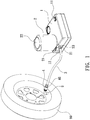
FIG. 1 is a perspective view showing the application of an anti-spray joint structure of a connection hose of a vehicle air compressor according to a preferred embodiment of the present invention. -
FIG. 2 is a perspective view showing the exploded components of the connection hose, the anti-spray joint structure, and an air nozzle of a tire according to the preferred embodiment of the present invention. -
FIG. 3 is a perspective view showing the exploded components of the anti-spray joint structure according to the preferred embodiment of the present invention. -
FIG. 4 is a perspective view showing the exploded components of a valve bolt assembly according to the preferred embodiment of the present invention. -
FIG. 5 is a side plan view showing the assembly of the anti-spray joint structure according to the preferred embodiment of the present invention. -
FIG. 6 is a cross sectional view showing the exploded components of a first segment and a second segment of the anti-spray joint structure according to the preferred embodiment of the present invention. -
FIG. 7 is a cross sectional view showing the assembly of a cap according to the preferred embodiment of the present invention. -
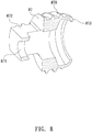
FIG. 8 is a cross-sectional perspective view showing the assembly of a mounting according to the preferred embodiment of the present invention. -
FIG. 9 is a perspective view showing the operation of the anti-spray joint structure of the connection hose of the vehicle air compressor according to the preferred embodiment of the present invention. -
FIG. 10 is another perspective view showing the operation of the anti-spray joint structure of the connection hose of the vehicle air compressor according to the preferred embodiment of the present invention. - With reference to
FIGS. 1-3 , a vehicle air compressor according to a preferred embodiment of the present invention comprises: abox 1, a sealant supply can 2, and aconnection hose 3. Thebox 1 includes abutton 11 fixed on a top thereof, acoupling orifice 12 defined on a peripheral side thereof, and a body (not shown) accommodated in thebox 1. Theconnection hose 3 includes afront connector 31 connected on a first end thereof, arear connector 4 connected on a second end thereof and having an anti-spray joint structure. The sealant supply can 2 is connected on thecoupling orifice 12, and the tire sealant supply can 2 includes anopen segment 21 extending downward, abottom fringe 22 extending upward, and asupply tube 23 configured to engage with thefront connector 31 of theconnection hose 3. Therear connector 4 is screwed with anair nozzle 9 of atire 99, when feeding chemical sealant and inflating compressed airs to thetire 99 which is broken. After thebox 1 is started by a vehicle power supply or other DC power supplies, the compressed airs of the vehicle air compressor force the chemical sealant of the sealant supply can 2 to flow into thetire 99 which is broken via theconnection hose 3, thus repairing and inflating thetire 99. - Referring to
FIGS. 2 ,3 , and5 , at least one anti-spray joint structure of theconnection hose 3 of the present invention is configured to avoid eruption of the chemical sealant and is arranged on therear connector 4, wherein a respective anti-spray joint structure includes afirst segment 41 and asecond segment 42 removed from and connected with thefirst segment 41 easily. Preferably, thefirst segment 41 is connected with thesecond segment 42 which has a channel of different sizes and shapes so as to be applicable fordifferent tires 99. - As shown in
FIGS. 3-10 , thefirst segment 41 has a receivingseat 5 and afitting seat 6, wherein thereceiving seat 5 has acavity 50, anopening 51 defined on a first end of thereceiving seat 5,female threads 510 formed on an inner wall of the opening 51,multiple recesses 511 defined on a distal end of the opening 51, and a throughhole 52 which is defined on a second end of thereceiving seat 5, has astop shoulder 521 extending inward around an inner wall of the throughhole 52, and communicates with thecavity 50. - The
fitting seat 6 includes acylindrical room 60 formed in a first end thereof, agroove 61 defined around an outer wall of thefitting seat 6, a steppedfixing portion 62 extending from a second end of thefitting seat 6, aconduit 63 defined in a center of thestepped fixing portion 62 and communicating with thecylindrical room 60, afirst seal ring 64 fitted on thegroove 61 of thefitting seat 6. - The stepped
fixing portion 62 of thefitting seat 6 is inserted through thecavity 50 and thestop shoulder 521 of the throughhole 52 from theopening 51 of thereceiving seat 5 to fit with the second end of theconnection hose 3, and apositioning ring 40 is configured to fix theconnection hose 3 and therear connector 4, as illustrated inFIG. 6 . - The
second segment 42 has acap 7 and avalve bolt assembly 8, as shown inFIGS. 3-7 , thecap 7 includes adefining segment 71 formed on a first end thereof and havingmale threads 710, ascrew hole 72 defined on a second end of thecap 7, at least oneretainer 712 surrounding an outer wall of thecap 7 between thedefining segment 71 and thescrew hole 72, thechannel 73 extending from an end of thescrew hole 72 and having a diameter which is less than a diameter of thescrew hole 72, astepped rib 74 formed between thescrew hole 72 and thechannel 73, amiddle rib 75 extending from thestepped rib 74 away from thescrew hole 72 and thechannel 73,female screwing section 750 formed around an inner wall of themiddle rib 75, apost 76 extending from an end of themiddle rib 75 away from thefemale screwing section 750 and having afixing orifice 760, and aconical fringe 77 formed between an inner wall of thepost 76 and an inner wall of themiddle rib 75, such that thechannel 73 is formed in different sizes so as to change a volume for changing flowing quantities of the chemical sealant and the compressed airs. - With reference to
FIG. 4 , thevalve bolt assembly 8 includes avalve bolt 81 formed in a column shape and having ahead 811 formed on a first end of thevalve bolt 81, multiple spacedribs 812 adjacent to thehead 811, and aprojection 813 extending from a second end of thevalve bolt 81; aspring 82 fitted with thevalve bolt 81 and abutting against the multiple spacedribs 812 of thevalve bolt 81; ahollow sleeve 83 having alocking shoulder 831 extending from a first end of thehollow sleeve 83, avalve holder 834 formed on a second end of thehollow sleeve 83, aprotrusion 832 and arecessed section 833 which are formed on an outer wall of thehollow sleeve 83 between thelocking shoulder 831 and thevalve holder 834. Referring toFIG. 6 , thevalve bolt 81 is fitted with thespring 82 and is put into the first end of thehollow sleeve 83 so that thespring 82 abuts against thevalve holder 834 and is surrounded by thehollow sleeve 83; awasher 84 fitted in therecessed section 833 of thehollow sleeve 83; asecond seal ring 85 fitted with a portion of thevalve bolt 81 adjacent to theprojection 813 and is positioned by alimiting element 86. Referring toFIG. 8 , amounting 87 includes amale screwing section 870, acentral passage 871 defined in themounting 87, agrip portion 872 formed on a first end of themounting 87, anarcuate engagement shoulder 873 surrounding around a mouth of themounting 87 and extending inward from a second end of themounting 87. When thespring 82, thevalve bolt 81, thesecond seal ring 85, thehollow sleeve 83 of thelimiting element 86, and themounting 87 are connected, thearcuate engagement shoulder 873 of themounting 87 is engaged with thelocking shoulder 831 of thehollow sleeve 83, thehead 811 of thevalve bolt 81 extends out of thecentral passage 871 of themounting 87 so that thespring 82 pushes thesecond seal ring 85 of thevalve bolt 81 to close thevalve holder 834 of thehollow sleeve 83. Thevalve bolt assembly 8 includes acontact member 88 fitted on thehead 811 of thevalve bolt 811 securely. When thevalve bolt assembly 8 is connected with thecap 7, themale screwing section 870 of themounting 87 is screwed with thefemale screwing section 750 of themiddle rib 75 of thecap 7, theprotrusion 832 and thewasher 84 of thevalve bolt assembly 8 contact with theconical fringe 77 of thecap 7, and thevalve holder 834 of thehollow sleeve 83, thesecond seal ring 85 of thevalve bolt 81, and thelimiting element 86 extend out of theorifice 760 of thepost 76 of thecap 7. Thevalve bolt assembly 8 further includes agasket 89 having anaperture 890 and fixed from thescrew hole 72 of thecap 7, wherein after theaperture 890 passes through thevalve bolt 81, thegasket 89 abuts against thestepped rib 74 of thecap 7; athird seal ring 711 fitted with thedefining segment 71 of thecap 7; wherein after thedefining segment 71 of thecap 7 is connected with thevalve bolt assembly 8 and is moved into thefirst segment 41, thedefining segment 71 is screwed with the opening 51 of thereceiving seat 5 which is coupled with thefitting seat 6. In other words, themale threads 710 of thedefining segment 71 of thecap 7 are screwed with thefemale threads 510 of the opening 51 of thereceiving seat 5, and the at least oneretainer 712 of thecap 7 is retained with themultiple recesses 511 of thereceiving seat 5, as illustrated inFIGS. 3 and5 , hence thefirst segment 41 is connected with thesecond segment 42 safely and securely. - With reference to
FIG. 9 , when thebutton 11 of thebox 1 is turned on, the compressed airs force the chemical sealant to flow, but the chemical sealant does not flow into thehollow sleeve 83 because thesecond seal ring 85 of thevalve bolt 81 contacts with thevalve holder 834 of thehollow sleeve 83 of thevalve bolt assembly 8 tightly, thus avoiding the eruption of the chemical sealant. - Referring to
FIGS. 1 and10 , when thescrew hole 72 of thecap 7 is screwed with theair nozzle 9 of thetire 99, thecontact member 88 of thevalve bolt 81 of therear connector 4 abuts against acentral needle 91 in theair nozzle 9 of thetire 99. Preferably, when thescrew hole 72 of therear connector 4 is screwed with theair nozzle 9 of thetire 99 completely, thecentral needle 91 of theair nozzle 9 is pushed by thevalve bolt 81 to press thespring 82, thesecond seal ring 85 of thevalve bolt 81 moves away from thevalve holder 834 of thehollow sleeve 83 so that thehollow sleeve 83 is communicated. In the meantime, the chemical sealant are pushed by the airs to flow into thetire 99 from theconduit 63 of thefitting seat 6 via thecylindrical room 60, thehollow sleeve 83, thecentral passage 871 of themounting 87, thechannel 73 of thecap 7, theaperture 890 of thegasket 89, thescrew hole 72, and theair nozzle 9, thus feeding the chemical sealant into thetire 99 and inflating the compressed airs into thetire 99. - Accordingly, the anti-spray joint structure of the
rear connector 4 is located on theconnection hose 3 and is configured to feed the chemical sealant and to inflate the compressed airs to thetire 99 which is broken. The anti-spray joint structure of therear connector 4 comprises thefirst segment 41 and thesecond segment 42 removed from and connected with thefirst segment 41 easily. Preferably, thefirst segment 41 is connected with thesecond segment 42 which has the channel of different sizes and volumes so as to be applicable fordifferent tires 99.
Claims (9)
- An anti-spray joint structure of a connection hose of a vehicle air compressor, the vehicle air compressor comprising:a box (1) including a body accommodated in the box (1) and started by a power supply to produce compressed airs;a sealant supply can (2) including an open segment (21) extending downward and configured to accommodate chemical sealant, and the sealant supply can (2) including a supply tube (23) arranged on the open segment (21);a connection hose (3) including a front connector (31) connected on a first end of the connection hose (3) and engaged with the supply tube (23) of the sealant supply can (2), a rear connector (4) connected on a second end of the connection hose (3) and fixed with an air nozzle (9) of a tire (99);characterized in that the rear connector (4) is an anti-spray joint structure and includes a first segment (41) and a second segment (42) removed from and connected with the first segment (41), and the first segment (41) is connected with the second segment (42) which has a channel of different sizes and shapes so as to be applicable for different tires (99) and to avoid eruption of the chemical sealant.
- The anti-spray joint structure as claimed in claim 1, characterized in that the first segment (41) has a receiving seat (5) and a fitting seat (6), wherein the receiving seat (5) has a cavity (50), an opening (51) defined on a first end of the receiving seat (5), female threads (510) formed on an inner wall of the opening (51), and a through hole (52) which is defined on a second end of the receiving seat (5), has a stop shoulder (521) extending inward around an inner wall of the through hole (52), and communicates with the cavity (50); the fitting seat (6) includes a cylindrical room (60) formed in a first end thereof, a groove (61) defined around an outer wall of the fitting seat (6), a stepped fixing portion (62) extending from a second end of the fitting seat (6), a conduit (63) defined in a center of the stepped fixing portion (62) and communicating with the cylindrical room (60), and a first seal ring (64) fitted on the groove (61) of the fitting seat (6); wherein the stepped fixing portion (62) of the fitting seat (6) is inserted through the cavity (50) and the stop shoulder (521) of the through hole (52) from the opening (51) of the receiving seat (5) to fit with the second end of the connection hose (3), and a positioning ring (40) is configured to fix the connection hose (3) and the rear connector (4).
- The anti-spray joint structure as claimed in claim 2, characterized in that the second segment (42) has a cap (7) and a valve bolt assembly (8), the cap (7) includes a defining segment (71) formed on a first end thereof and having male threads (710), a screw hole (72) defined on a second end of the cap (7), the channel (73) extending from an end of the screw hole (72) and having a diameter which is less than a diameter of the screw hole (72), a stepped rib (74) formed between the screw hole (72) and the channel (73), a middle rib (75) extending from the stepped rib (74) away from the screw hole (72) and the channel (73), female screwing section (750) formed around an inner wall of the middle rib (75), a post (76) extending from an end of the middle rib (75) away from the female screwing section (750) and having a fixing orifice (760), and a conical fringe (77) formed between an inner wall of the post (76) and an inner wall of the middle rib (75).
- The anti-spray joint structure as claimed in claim 3, characterized in that the valve bolt assembly (8) includes a valve bolt (81) formed in a column shape and having a head (811) formed on a first end of the valve bolt (81), multiple spaced ribs (812) adjacent to the head (811), and a projection (813) extending from a second end of the valve bolt (81); a spring (82) fitted with the valve bolt (81) and abutting against the multiple spaced ribs (812) of the valve bolt (81); a hollow sleeve (83) having a locking shoulder (831) extending from a first end of the hollow sleeve (83), a valve holder (834) formed on a second end of the hollow sleeve (83), a protrusion (832) and a recessed section (833) which are formed on an outer wall of the hollow sleeve (83) between the locking shoulder (831) and the valve holder (834).
- The anti-spray joint structure as claimed in claim 4, characterized in that the valve bolt (81) is fitted with the spring (82) and is put into the first end of the hollow sleeve (83) so that the spring (82) abuts against the valve holder (834) and is surrounded by the hollow sleeve (83); a second seal ring (85) fitted with a portion of the valve bolt (81) adjacent to the projection (813), a mounting (87) includes a male screwing section (870), and a central passage (871) defined in the mounting (87); wherein when the spring (82), the valve bolt (81), the second seal ring (85), the hollow sleeve (83) of the limiting element (86), and the mounting (87) are connected, the head (811) of the valve bolt (81) extends out of the central passage (871) of the mounting (87) so that the spring (82) pushes the second seal ring (85) of the valve bolt (81) to close the valve holder (834) of the hollow sleeve (83); when the valve bolt assembly (8) is connected with the cap (7), the male screwing section (870) of the mounting (87) is screwed with the female screwing section (750) of the middle rib (75) of the cap (7), and the valve holder (834) of the hollow sleeve (83) and the second seal ring (85) of the valve bolt (81) extend out of the orifice (760) of the post (76) of the cap (7).
- The anti-spray joint structure as claimed in claim 5, characterized in that a washer (84) is fitted in the recessed section (833) of the hollow sleeve (83), the protrusion (832) and the washer (84) of the valve bolt assembly (8) contact with the conical fringe (77) of the cap (7); the second seal ring (85) is positioned by a limiting element (86); the valve bolt assembly (8) further includes a gasket (89) having an aperture (890) and fixed from the screw hole (72) of the cap (7), wherein after the aperture (890) passes through the valve bolt (81), the gasket (89) abuts against the stepped rib (74) of the cap (7); a third seal ring (711) fitted with the defining segment (71) of the cap (7); wherein after the defining segment (71) of the cap (7) is connected with the valve bolt assembly (8) and is moved into the first segment (41), the defining segment (71) is screwed with the opening (51) of the receiving seat (5) which is coupled with the fitting seat (6), and the male threads (710) of the defining segment (71) of the cap (7) are screwed with the female threads (510) of the opening (51) of the receiving seat (5).
- The anti-spray joint structure as claimed in claim 5, characterized in that the mounting (87) has a grip portion (872) formed on a first end of the mounting (87), and the mounting (87) has an arcuate engagement shoulder (873) surrounding around a mouth of the mounting (87) and extending inward from a second end of the mounting (87), wherein the arcuate engagement shoulder (873) of the mounting (87) is engaged with the locking shoulder (831) of the hollow sleeve (83).
- The anti-spray joint structure as claimed in claim 4, wherein the valve bolt assembly (8) further includes a contact member (88) fitted on the head (811) of the valve bolt (811) securely.
- The anti-spray joint structure as claimed in claim 6, characterized in that the receiving seat (5) further includes multiple recesses (511) defined on a distal end of the opening (51); wherein at least one retainer (712) surround an outer wall of the cap (7) between the defining segment (71) and the screw hole (72), and the at least one retainer (712) of the cap (7) is retained with the multiple recesses (511) of the receiving seat (5).
Applications Claiming Priority (1)
| Application Number | Priority Date | Filing Date | Title |
|---|---|---|---|
| TW108131970A TWI727417B (en) | 2019-09-04 | 2019-09-04 | Anti-spray joint structure of connection hose of vehicle air compressor |
Publications (1)
| Publication Number | Publication Date |
|---|---|
| EP3797976A1 true EP3797976A1 (en) | 2021-03-31 |
Family
ID=72521361
Family Applications (1)
| Application Number | Title | Priority Date | Filing Date |
|---|---|---|---|
| EP20020386.7A Withdrawn EP3797976A1 (en) | 2019-09-04 | 2020-08-26 | Anti-spray joint structure of connection hose of vehicle air compressor |
Country Status (6)
| Country | Link |
|---|---|
| EP (1) | EP3797976A1 (en) |
| JP (2) | JP3229328U (en) |
| KR (1) | KR102371928B1 (en) |
| CN (2) | CN212774678U (en) |
| DE (1) | DE202020104842U1 (en) |
| TW (1) | TWI727417B (en) |
Cited By (1)
| Publication number | Priority date | Publication date | Assignee | Title |
|---|---|---|---|---|
| CN118757624A (en) * | 2024-07-30 | 2024-10-11 | 中山市天浩塑料制品实业有限公司 | Sealing joints |
Families Citing this family (2)
| Publication number | Priority date | Publication date | Assignee | Title |
|---|---|---|---|---|
| TWI708905B (en) * | 2019-12-25 | 2020-11-01 | 葳仂特國際有限公司 | Hose rotatable joint |
| CN121939069A (en) | 2021-03-04 | 2026-04-28 | 株式会社Lg新能源 | Battery pack and vehicle containing the battery pack |
Citations (10)
| Publication number | Priority date | Publication date | Assignee | Title |
|---|---|---|---|---|
| US1484342A (en) * | 1919-04-05 | 1924-02-19 | Schweinert Maximilian Charles | Adapter for pump couplings |
| EP0743203A1 (en) * | 1995-05-15 | 1996-11-20 | innovative technik marketing (itm) | Adapter device |
| DE20010544U1 (en) * | 2000-06-13 | 2001-02-22 | Völker, Johannes, 34628 Willingshausen | Adapter for bicycle light pump valves |
| DE202006002485U1 (en) * | 2006-02-15 | 2006-04-13 | Golikov, Andrej | Valve for a pneumatic tire comprises a unit which serves for connecting the valve to a gas outlet of a pneumatic pressure source, and incorporates a circumferential engagement flange |
| DE102006007211A1 (en) * | 2006-02-15 | 2007-08-23 | Andrej Golikov | Valve for inflation of a pneumatic tire, with a connection to the compressed air supply, has a peripheral flange to act as a snap coupling in a non-return valve structure |
| EP2390502A1 (en) * | 2009-07-17 | 2011-11-30 | Ying-Che Huang | Inflation nozzle capable of connecting with two types of tire valves |
| DE202012100671U1 (en) * | 2011-03-10 | 2012-06-26 | Wen-San Jhou | Device for sealing and inflating inflatable objects |
| DE202012103464U1 (en) * | 2011-11-02 | 2012-12-20 | Wen-San Jhou | From a vehicle entrained air compression device |
| DE202013101644U1 (en) * | 2012-04-27 | 2013-08-09 | Wen-San Jhou | From a vehicle entrained air compression device |
| DE202018107206U1 (en) * | 2017-12-25 | 2019-01-11 | Unik World Industrial Co., Ltd. | Design of a back-up fuse adapter for connection to a flexible connection hose of a vehicle-carried air compression device for repairing and filling damaged tires |
Family Cites Families (9)
| Publication number | Priority date | Publication date | Assignee | Title |
|---|---|---|---|---|
| CN2187245Y (en) * | 1994-03-10 | 1995-01-11 | 庄泽民 | Valve of inner tube |
| JP5021242B2 (en) * | 2006-06-20 | 2012-09-05 | 株式会社ブリヂストン | Sealing pump up device |
| TWI482908B (en) * | 2011-03-07 | 2015-05-01 | 周文三 | Air compressor for vehicle |
| CN202391694U (en) * | 2011-11-10 | 2012-08-22 | 周文三 | Joint structure of series hose of vehicle-mounted air compressor |
| KR101757575B1 (en) * | 2016-01-11 | 2017-07-13 | 에스지서보(주) | Quick coupling device |
| CN106014935B (en) * | 2016-05-13 | 2018-09-04 | 威伯科汽车控制系统(中国)有限公司 | A kind of inlet suction port and the interior relief arrangement of automobile air compressor |
| CN105937490B (en) * | 2016-06-17 | 2018-03-30 | 安徽阜阳风劲霸机电有限公司 | Joint design for gas output |
| CN207500561U (en) * | 2017-10-27 | 2018-06-15 | 上海华汇机电有限公司 | One-way sealing formula gas nozzle |
| CN109139425A (en) * | 2018-11-05 | 2019-01-04 | 南通市红星空压机配件制造有限公司 | Oil-injection-preventing air inlet valve for electric bus air compressor |
-
2019
- 2019-09-04 TW TW108131970A patent/TWI727417B/en active
-
2020
- 2020-08-20 DE DE202020104842.2U patent/DE202020104842U1/en not_active Expired - Lifetime
- 2020-08-20 KR KR1020200104515A patent/KR102371928B1/en active Active
- 2020-08-25 CN CN202021792638.0U patent/CN212774678U/en not_active Expired - Fee Related
- 2020-08-25 CN CN202010862496.9A patent/CN112443476A/en not_active Withdrawn
- 2020-08-26 EP EP20020386.7A patent/EP3797976A1/en not_active Withdrawn
- 2020-09-03 JP JP2020003768U patent/JP3229328U/en active Active
- 2020-09-03 JP JP2020147997A patent/JP7002615B2/en not_active Expired - Fee Related
Patent Citations (10)
| Publication number | Priority date | Publication date | Assignee | Title |
|---|---|---|---|---|
| US1484342A (en) * | 1919-04-05 | 1924-02-19 | Schweinert Maximilian Charles | Adapter for pump couplings |
| EP0743203A1 (en) * | 1995-05-15 | 1996-11-20 | innovative technik marketing (itm) | Adapter device |
| DE20010544U1 (en) * | 2000-06-13 | 2001-02-22 | Völker, Johannes, 34628 Willingshausen | Adapter for bicycle light pump valves |
| DE202006002485U1 (en) * | 2006-02-15 | 2006-04-13 | Golikov, Andrej | Valve for a pneumatic tire comprises a unit which serves for connecting the valve to a gas outlet of a pneumatic pressure source, and incorporates a circumferential engagement flange |
| DE102006007211A1 (en) * | 2006-02-15 | 2007-08-23 | Andrej Golikov | Valve for inflation of a pneumatic tire, with a connection to the compressed air supply, has a peripheral flange to act as a snap coupling in a non-return valve structure |
| EP2390502A1 (en) * | 2009-07-17 | 2011-11-30 | Ying-Che Huang | Inflation nozzle capable of connecting with two types of tire valves |
| DE202012100671U1 (en) * | 2011-03-10 | 2012-06-26 | Wen-San Jhou | Device for sealing and inflating inflatable objects |
| DE202012103464U1 (en) * | 2011-11-02 | 2012-12-20 | Wen-San Jhou | From a vehicle entrained air compression device |
| DE202013101644U1 (en) * | 2012-04-27 | 2013-08-09 | Wen-San Jhou | From a vehicle entrained air compression device |
| DE202018107206U1 (en) * | 2017-12-25 | 2019-01-11 | Unik World Industrial Co., Ltd. | Design of a back-up fuse adapter for connection to a flexible connection hose of a vehicle-carried air compression device for repairing and filling damaged tires |
Cited By (1)
| Publication number | Priority date | Publication date | Assignee | Title |
|---|---|---|---|---|
| CN118757624A (en) * | 2024-07-30 | 2024-10-11 | 中山市天浩塑料制品实业有限公司 | Sealing joints |
Also Published As
| Publication number | Publication date |
|---|---|
| TWI727417B (en) | 2021-05-11 |
| DE202020104842U1 (en) | 2020-09-22 |
| TW202111209A (en) | 2021-03-16 |
| KR102371928B1 (en) | 2022-03-07 |
| JP7002615B2 (en) | 2022-02-04 |
| JP2021038849A (en) | 2021-03-11 |
| CN112443476A (en) | 2021-03-05 |
| JP3229328U (en) | 2020-12-03 |
| KR20210029091A (en) | 2021-03-15 |
| CN212774678U (en) | 2021-03-23 |
Similar Documents
| Publication | Publication Date | Title |
|---|---|---|
| US11548333B2 (en) | Check joint structure for connection of air nozzle of tire and connection hose of air compressor | |
| US11046129B2 (en) | Anti-spray joint structure of connection hose of vehicle air compressor | |
| US11052621B2 (en) | Combination structure for a hose connected between an air compressor and a tire | |
| US11235629B2 (en) | Anti-jet joint structure of connection hose of vehicle air compressor | |
| EP3797976A1 (en) | Anti-spray joint structure of connection hose of vehicle air compressor | |
| EP3797978A1 (en) | Anti-spray structure for connection of air nozzle of tire of vehicle and connection hose of air compressor | |
| KR101059660B1 (en) | Connector for discharging liquid from the tank | |
| EP3202601A1 (en) | Pneumatic valve adaptor | |
| US20210016616A1 (en) | Air compressor capable of inflating air and supplying sealant | |
| US11346480B2 (en) | Connecting kit for an irrigation hose | |
| US11358351B2 (en) | Anti-spray joint structure of connection hose of vehicle air compressor | |
| US10738809B2 (en) | Connection devices for fluidic devices | |
| US20200101487A1 (en) | Sealant dispenser | |
| US11149892B2 (en) | Check structure for connection of air nozzle of tire and connection hose of air compressor | |
| US11143346B2 (en) | Check joint structure for connection of an air nozzle of a tire and a connector of a connection hose of an air compressor | |
| US10288202B2 (en) | Installation between valve connector and pipe of ice maker | |
| JP2022154065A (en) | Jet pipe nozzle unit | |
| KR200421703Y1 (en) | Atomizer hose connection structure | |
| WO2025245524A1 (en) | A pump head for a pneumatic valve system |
Legal Events
| Date | Code | Title | Description |
|---|---|---|---|
| PUAI | Public reference made under article 153(3) epc to a published international application that has entered the european phase |
Free format text: ORIGINAL CODE: 0009012 |
|
| STAA | Information on the status of an ep patent application or granted ep patent |
Free format text: STATUS: REQUEST FOR EXAMINATION WAS MADE |
|
| 17P | Request for examination filed |
Effective date: 20201112 |
|
| AK | Designated contracting states |
Kind code of ref document: A1 Designated state(s): AL AT BE BG CH CY CZ DE DK EE ES FI FR GB GR HR HU IE IS IT LI LT LU LV MC MK MT NL NO PL PT RO RS SE SI SK SM TR |
|
| AX | Request for extension of the european patent |
Extension state: BA ME |
|
| STAA | Information on the status of an ep patent application or granted ep patent |
Free format text: STATUS: THE APPLICATION HAS BEEN WITHDRAWN |
|
| 18W | Application withdrawn |
Effective date: 20230811 |