EP3797659A1 - Befestigungsvorrichtung - Google Patents
Befestigungsvorrichtung Download PDFInfo
- Publication number
- EP3797659A1 EP3797659A1 EP19199532.3A EP19199532A EP3797659A1 EP 3797659 A1 EP3797659 A1 EP 3797659A1 EP 19199532 A EP19199532 A EP 19199532A EP 3797659 A1 EP3797659 A1 EP 3797659A1
- Authority
- EP
- European Patent Office
- Prior art keywords
- support
- fastening device
- fastening
- profile
- bearing plate
- Prior art date
- Legal status (The legal status is an assumption and is not a legal conclusion. Google has not performed a legal analysis and makes no representation as to the accuracy of the status listed.)
- Granted
Links
Images





Classifications
-
- A—HUMAN NECESSITIES
- A47—FURNITURE; DOMESTIC ARTICLES OR APPLIANCES; COFFEE MILLS; SPICE MILLS; SUCTION CLEANERS IN GENERAL
- A47K—SANITARY EQUIPMENT; ACCESSORIES THEREFOR, e.g. TOILET ACCESSORIES
- A47K3/00—Baths; Showers; Appurtenances therefor
- A47K3/16—Devices for fastening baths to floors or walls; Adjustable bath feet ; Lining panels or attachments therefor
-
- F—MECHANICAL ENGINEERING; LIGHTING; HEATING; WEAPONS; BLASTING
- F16—ENGINEERING ELEMENTS AND UNITS; GENERAL MEASURES FOR PRODUCING AND MAINTAINING EFFECTIVE FUNCTIONING OF MACHINES OR INSTALLATIONS; THERMAL INSULATION IN GENERAL
- F16B—DEVICES FOR FASTENING OR SECURING CONSTRUCTIONAL ELEMENTS OR MACHINE PARTS TOGETHER, e.g. NAILS, BOLTS, CIRCLIPS, CLAMPS, CLIPS OR WEDGES; JOINTS OR JOINTING
- F16B2/00—Friction-grip releasable fastenings
- F16B2/02—Clamps, i.e. with gripping action effected by positive means other than the inherent resistance to deformation of the material of the fastening
- F16B2/06—Clamps, i.e. with gripping action effected by positive means other than the inherent resistance to deformation of the material of the fastening external, i.e. with contracting action
- F16B2/065—Clamps, i.e. with gripping action effected by positive means other than the inherent resistance to deformation of the material of the fastening external, i.e. with contracting action using screw-thread elements
-
- F—MECHANICAL ENGINEERING; LIGHTING; HEATING; WEAPONS; BLASTING
- F16—ENGINEERING ELEMENTS AND UNITS; GENERAL MEASURES FOR PRODUCING AND MAINTAINING EFFECTIVE FUNCTIONING OF MACHINES OR INSTALLATIONS; THERMAL INSULATION IN GENERAL
- F16B—DEVICES FOR FASTENING OR SECURING CONSTRUCTIONAL ELEMENTS OR MACHINE PARTS TOGETHER, e.g. NAILS, BOLTS, CIRCLIPS, CLAMPS, CLIPS OR WEDGES; JOINTS OR JOINTING
- F16B2/00—Friction-grip releasable fastenings
- F16B2/02—Clamps, i.e. with gripping action effected by positive means other than the inherent resistance to deformation of the material of the fastening
- F16B2/06—Clamps, i.e. with gripping action effected by positive means other than the inherent resistance to deformation of the material of the fastening external, i.e. with contracting action
- F16B2/10—Clamps, i.e. with gripping action effected by positive means other than the inherent resistance to deformation of the material of the fastening external, i.e. with contracting action using pivoting jaws
-
- F—MECHANICAL ENGINEERING; LIGHTING; HEATING; WEAPONS; BLASTING
- F16—ENGINEERING ELEMENTS AND UNITS; GENERAL MEASURES FOR PRODUCING AND MAINTAINING EFFECTIVE FUNCTIONING OF MACHINES OR INSTALLATIONS; THERMAL INSULATION IN GENERAL
- F16B—DEVICES FOR FASTENING OR SECURING CONSTRUCTIONAL ELEMENTS OR MACHINE PARTS TOGETHER, e.g. NAILS, BOLTS, CIRCLIPS, CLAMPS, CLIPS OR WEDGES; JOINTS OR JOINTING
- F16B37/00—Nuts or like thread-engaging members
- F16B37/16—Wing-nuts
-
- F—MECHANICAL ENGINEERING; LIGHTING; HEATING; WEAPONS; BLASTING
- F16—ENGINEERING ELEMENTS AND UNITS; GENERAL MEASURES FOR PRODUCING AND MAINTAINING EFFECTIVE FUNCTIONING OF MACHINES OR INSTALLATIONS; THERMAL INSULATION IN GENERAL
- F16B—DEVICES FOR FASTENING OR SECURING CONSTRUCTIONAL ELEMENTS OR MACHINE PARTS TOGETHER, e.g. NAILS, BOLTS, CIRCLIPS, CLAMPS, CLIPS OR WEDGES; JOINTS OR JOINTING
- F16B5/00—Joining sheets or plates, e.g. panels, to one another or to strips or bars parallel to them
- F16B5/12—Fastening strips or bars to sheets or plates, e.g. rubber strips, decorative strips for motor vehicles, by means of clips
- F16B5/123—Auxiliary fasteners specially designed for this purpose
Definitions
- the present invention relates to a fastening device according to the preamble of claim 1.
- a fastening device for fastening a sanitary tub element has become known.
- the fastening device is clamped to a fastening profile mounted on a wall and then a clamping element is tightened by means of a wing nut and the tub element is clamped against the wall.
- a disadvantage of the technical teaching of the DE 10 2012 007 309 is the support of the fastening device on the fastening profile.
- the invention is based on an object of specifying a fastening device which overcomes the disadvantages of the prior art.
- a particularly preferred object is to specify a fastening device which allows improved support.
- a fastening device is used to fix an edge of a sanitary tub element, such as a bathtub or shower tray, against a wall, the fastening device being connectable to a fastening profile extending in the direction of a profile pocket.
- the mounting profile is fixed to the Wall mounted.
- the arrangement of two receiving spaces has the advantage that the fastening device can be supported or held on two holding webs on the fastening profile. There are two determined points on the fastening profile where the support takes place ..
- the fastening profile is preferably a C-profile with a base leg, from which two side legs extend away. Each of the side legs has a free end from which the retaining webs protrude.
- the holding webs extend into the space between the two side legs.
- the side limbs are preferably of the same length as seen from the base limb, so that the holding webs are at the same height as seen from the base limb.
- the base leg preferably has Openings with which the fastening profile can be fastened against a wall by means of screws.
- the actuating element is preferably a screw and a nut, the screw extending away from the bearing plate and the nut acting on the clamping element.
- a hexagon nut or a wing nut can be used as the nut.
- the clamping element and the bearing plate are preferably made of a metallic material.
- the actuating element is also preferably made of metal.
- the support element is preferably made of plastic.
- the receiving spaces are preferably designed in such a way that the fastening device can be displaced in the direction of the profile axis relative to the fastening profile.
- the receiving spaces are preferably open to the side as seen in the direction of the profile axis.
- the displaceability has the advantage that the fastening device can be connected to the fastening profile, the fastening device then being able to be precisely positioned with respect to the fastening profile.
- the recording rooms are therefore with play to the holding webs.
- Each of the receiving spaces is preferably delimited by a first receiving surface and a second receiving surface that runs essentially parallel to the first receiving surface. In the assembled position, the receiving surfaces rest on the surfaces of the holding web.
- the retaining web extends into the receiving space between the two receiving surfaces.
- the distance between the two receiving surfaces is preferably greater than the thickness of the retaining web, so that corresponding play can arise.
- the receiving spaces are preferably apart from the two receiving surfaces and a base area which extends from the one receiving area to the other receiving area, freely accessible, the receiving spaces being essentially U-shaped as seen in the direction of the profile axis.
- one of the receiving surfaces is arranged on the support element and the other of the receiving surfaces is arranged on the bearing plate.
- the first variant has the advantage that the support element provides part of the mounting of the fastening element, whereby a mounting is provided that can withstand higher loads.
- both receiving surfaces are arranged on the support element.
- the second variant has the advantage of being easy to manufacture.
- the receiving spaces are preferably fixed in terms of their clear width.
- the receiving spaces are particularly preferably designed in such a way that the holding webs are not clamped in the receiving spaces.
- the bearing plate is preferably secured to the support element with at least one latching element formed on the support element, the latching element lying on the underside of the support.
- the bearing plate is preferably placed firmly on the underside of the support.
- the bearing plate is preferably supported on both retaining webs. This means that the bearing plate extends from one of the holding webs to the other of the holding webs and is supported on both holding webs.
- the clamping element is preferably supported with a support section on the support top.
- a supporting force can act on the support element and possibly on the bearing plate via the support top.
- the bearing plate preferably has a cranked section.
- the cranked section is preferably designed in such a way that the bearing plate strikes the holding web from below on the side of the fastening element on which the clamping surface lies, and the bearing plate strikes the holding web at the opposite point from above. As a result, the clamping force from the clamping element can be easily transferred into the Fastening profile are initiated.
- the cranked section is preferably designed such that the bearing plate can be brought into contact on one side with its surface facing the support element and on the other side with its surface facing away from the support element with the retaining web of the fastening profile.
- the cranked section is preferably guided through a recess on the support element in such a way that part of the bearing plate extends on the support top side and another part of the support plate extends on the support bottom side.
- the support element preferably has at least one spring arm which acts on the clamping element and presses the clamping element away from the support element against the action of the actuating element.
- the receiving space is preferably designed in such a way that the fastening device can be connected to the fastening profile via a pivoting movement about a pivoting axis which is oriented parallel to the central axis.
- the base of the receiving space preferably has a first surface area and a second surface area, the first surface area being inclined at an angle to the second surface area such that the fastening device can be inserted between the retaining webs of the fastening profile and can then be pivoted about the pivot axis.
- the support element has guide tabs, which guide tabs protrude from the support top and guide the clamping element laterally and / or that the support element has support tabs, which support tabs protrude from the support underside, wherein the support tabs protrude into the space between the two retaining webs of the fastening profile when the Fastening device is connected to the fastening profile.
- the support brackets can come into contact with the base leg of the fastening profile.
- a system comprises a fastening device according to the above description and a fastening profile with two holding webs that are spaced apart from one another, with one holding web projecting into each receiving space in the connected state.
- the fastening device is preferably supported exclusively on the fastening profile. This exclusive support takes place via the inclusion of the retaining webs through the receiving spaces. This means that no support on other structural elements, such as the wall, is necessary. This allows a system to be specified which can be used independently of specific installation situations.
- FIG 1 is a perspective view of a fastening device 1 for fixing an edge of a sanitary tub element, such as a bathtub or a shower tray, shown against a wall.
- a fastening device 1 for fixing an edge of a sanitary tub element, such as a bathtub or a shower tray, shown against a wall.
- the fastening device 1 according to the Figure 1 shown in more detail in combination with a mounting profile 2.
- the fastening device 1 and the fastening profile 2 form a system for fixing an edge of a sanitary tub element, such as a bathtub or a shower tray, against a wall.
- the fastening profile 2 extends along a profile axis P C-profile.
- the C-profile has a base leg 25 as a base.
- the fastening profile 2 is screwed to a wall via its base surface 26.
- Each of the side legs 26 has a free end 28.
- holding webs 11 protrude from the side leg 26.
- the holding webs 11 run essentially parallel to the base limb 25.
- the holding webs 11 also extend from the side limb 26 towards one another.
- the base leg 25, the side legs 26 and the holding webs 11 delimit an intermediate space 24.
- the fastening device 1 can be connected to the fastening profile as described below.
- the fastening device 1 is brought into contact with the holding webs 11.
- parts of the fastening device 1 protrude into the space 24 and other parts extend out of the space 24.
- the Figures 1 and 2 show the fastening device 1 with its individual parts.
- the fastening device 1 essentially comprises a support element 3, a clamping element 6, an actuating element 8 and a bearing plate 9.
- the support element 3 has a support top 4 and a support bottom 5.
- the clamping element 6 rests on the support top 4 and the bearing plate 9 rests on the support bottom 5.
- the clamping element 6 has a clamping surface 7 which can be brought into contact with the tub element.
- the tub element can be pressed against the wall via the clamping surface 7.
- the clamping surface 7 protrudes in the assembled state, as in the Figures 3 to 5 shown laterally beyond the mounting profile 1.
- a rubber grommet 30 can be arranged in the area of the clamping surface 7.
- a clamping force can be applied to the clamping element 6 with the actuating element 8.
- the clamping surface 7 is pressed against the tub element, not shown in the figures.
- the clamping element 6 is moved essentially against the support element 3 or the fastening profile 1, whereby the clamping surface 7 is also moved in the aforementioned direction.
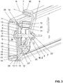
- the movement of the clamping element 6 or the clamping surface 7 is in the Figure 3 shown by arrow B.
- the actuating element 8 extends from the bearing plate 9 through the support element 3 to the clamping element 6 along a central axis M.
- the actuating element 8 is in the embodiment shown, as from the exploded view of FIG Figure 2 shown, a screw with a threaded portion 31.
- the threaded portion 31 is connected to a wing nut 32.
- the threaded section 31 extends through an opening 33 on the support element 3 and on the bearing plate 9 and through an opening 34 on the clamping element 6.
- the screw is at least non-rotatably connected to the bearing plate 9.
- the fastening device 1 has two receiving spaces 10 lying opposite one another with respect to the fastening element 8 or with respect to the central axis M.
- a retaining web 11 of the fastening profile 2 protrudes into each of the receiving spaces 10.
- the fastening device 1 is secured to the fastening profile 2 via this protrusion.
- a holding web 11 protrudes from the left into the one receiving space 10 and that the other holding web 11 protrudes from the right into the other of the two receiving spaces 10.
- This type of mounting has the particular advantage of a double support of the fastening device 1 on the fastening profile 2. In this way, forces can be introduced into the fastening profile 2 more easily.
- the fastening device 1 is well supported by the mounting via the two receiving spaces 10 on the fastening profile 2. Further support on the wall on which the fastening profile 2 is mounted is therefore not necessary.
- the clamping element 6 also has a support section 27. With the support section 27, the clamping element 6 is supported on the support upper side 4 of the support element 3.
- the support section 27 is arranged opposite the clamping surface 7.
- the bearing plate 9 and also the clamping element 6 are preferably made of metal, while the support element 3 is made of plastic.
- the receiving spaces 10 are designed in such a way that the fastening device 1 can be displaced in the direction of the profile axis P relative to the fastening profile 2. This means that the fastening device 1 can be roughly placed on the fastening profile 2 and then shifted along the profile axis P in the sense of a fine adjustment.
- the receiving spaces 10 accordingly have play with respect to the holding webs 11, so that the movement along the profile axis P is made possible accordingly.
- Each of the receiving spaces 10 is laterally bounded by a first receiving surface 12 and a second receiving surface 13 essentially parallel to the first receiving surface 12. Essentially parallel means that slight angular deviations from parallelism are possible.
- the receiving surfaces 12, 13 are at a distance from one another which is greater than the thickness of the holding web 11. Furthermore, the depth of the receiving spaces 10 is limited transversely to the profile axis P by a base area 14. The distance between the two base surfaces 14 of the two opposing receiving spaces 10 is preferably the same as or slightly smaller than the distance between the two holding webs 11, so that the fastening device 1 can be displaced relative to the fastening profile 2.
- the receiving spaces 10 are freely accessible. This means that there are no further restrictions with regard to any boundary surfaces of the recording rooms. When viewed in the direction of the profile axis P, the receiving spaces 10 are therefore essentially U-shaped.
- the bearing plate 9 can be advantageously positioned accordingly.
- the bearing plate 9 is designed in such a way that it is supported on both retaining webs 11. This support has the advantage that forces which act on the bearing plate 9 via the clamping surface 7 and the clamping element 6 and also the actuating element 8 can be easily introduced into the fastening profile 2.
- the bearing plate 9 has a cranked section 16.
- the bearing plate 9 lies in the fastening device 1 in such a way that the bearing plate 9 strikes the holding web 11 from below on the side of the fastening element 1 on which the clamping surface lies and that the bearing plate 9 on the opposite side hits the holding web 11 from above strikes. In this way, an improved introduction of force can also be achieved.
- the cranked section 16 protrudes through a recess 19 on the support element 3 from below upwards, in such a way that part of the bearing plate 9 extends on the side of the support top 4 and that another part of the bearing plate 9 extends on the side of the support underside extends.
- the cranked section is preferably designed such that the bearing plate 9 can be brought into contact on one side with its surface 17 facing the support element and on the other side with its surface 18 facing away from the support element with the retaining web of the fastening profile.
- the bearing plate 9 is fixedly arranged on the support underside 5.
- the bearing plate 9, as already mentioned, also extends or can extend onto the support upper side 4.
- the bearing plate 9 is secured to the support element 3 via at least one latching element 15.
- the at least one latching element 15 lie on the support underside 5.
- the support element 3 has at least one spring arm 20 which acts on the clamping element 6 and presses the clamping element 6 away from the support element 3 against the action of the actuating element 8.
- the spring action of the spring arm 20 essentially serves to hold the clamping element 6 under a slight bias so that no rattling noises arise during transport and assembly.
- the actuating element 8 also secures the bearing plate 9 against the support underside 4.
- the at least one spring arm 20 can press the bearing plate 9 against the support underside 4 due to the connection with the fastening element 8.
- the support element 3 also has guide tabs 22.
- the guide tabs 22 protrude from the support top 4 and guide the clamping element 6 laterally.
- the support element 3 On the Support underside 5, the support element 3 has support tabs 23 which protrude from the support underside 5. The support tabs 23 protrude into the space 24 between the two holding webs 11 of the fastening profile 2 when the fastening device 1 is connected to the fastening profile.
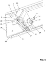
- FIG. 6 an assembly step of the fastening device 1 to the fastening profile 2 is shown.
- the receiving spaces 10 are designed in such a way that the fastening device 1 can be connected to the fastening profile 2 via a pivoting movement V about a pivoting axis Z, which is oriented parallel to the central axis M.
- the fastening device is now pivoted along the pivoting movement V and the pivot axis Z until the fastening device 1 in the Figures 3 to 5 position shown.
- a simple assembly of the fastening device 1 can be achieved by this pivoting.
- the base surface 14, as in FIG Figures 1 and 6th as can be seen from FIG.
- a first surface area 21 and a second surface area 29 are oriented at an angle to the second surface area 29 in such a way that the fastening device as in FIGS Figures 6 and 7th shown, can be inserted at an angle between the holding webs 11 of the fastening profile 2 and is then pivotable about the pivot axis Z.
- the first surface area 21 runs parallel to the profile axis P and after the pivoting, the second surface area 29 runs parallel to the profile axis P.
Landscapes
- Health & Medical Sciences (AREA)
- Public Health (AREA)
- Epidemiology (AREA)
- General Health & Medical Sciences (AREA)
- Clamps And Clips (AREA)
- Connection Of Plates (AREA)
Abstract
Description
- Die vorliegende Erfindung betrifft eine Befestigungsvorrichtung nach dem Oberbegriff von Anspruch 1.
- Aus der
DE 10 2012 007 309 ist eine Befestigungsvorrichtung zur Befestigung eines sanitären Wannenelementes bekannt geworden. Dabei wird die Befestigungsvorrichtung zu einem an einer Wand montierten Befestigungsprofil geklemmt und anschliessend wird ein Klemmelement mittels einer Flügelmutter festgezogen und das Wannenelement wird gegen die Wand geklemmt. - Nachteilig an der technischen Lehre der
DE 10 2012 007 309 ist die Abstützung der Befestigungsvorrichtung am Befestigungsprofil. - Ausgehend von diesem Stand der Technik liegt der Erfindung eine Aufgabe zugrunde, eine Befestigungsvorrichtung anzugeben, welche die Nachteile des Standes der Technik überwindet. Eine besonders bevorzugte Aufgabe ist es, eine Befestigungsvorrichtung anzugeben, welche eine verbesserte Abstützung erlaubt.
- Diese bevorzugte Aufgabe löst der Gegenstand von Anspruch 1. Demgemäss dient eine Befestigungsvorrichtung der Fixierung eines Randes eines sanitären Wannenelementes, wie eine Badewanne oder eine Duschwanne, gegen eine Wand, wobei die Befestigungsvorrichtung mit einem sich in Richtung einer Profilasche erstreckendem Befestigungsprofil verbindbar ist. Typischerweise ist das Befestigungsprofil fest an der Wand montiert.
- Die Befestigungsvorrichtung umfasst
- ein Supportelement mit einer Supportoberseite und einer Supportunterseite,
- ein auf der Supportoberseite aufliegendes Klemmelement mit einer mit dem Wannenelement in Kontakt bringbaren Klemmfläche,
- ein Betätigungselement, mit welchem eine Klemmkraft auf das Klemmelement aufbringbar ist, und
- eine auf der Supportunterseite aufliegende Lagerplatte.
- Die Anordnung von zwei Aufnahmeräumen hat den Vorteil, dass die Befestigungsvorrichtung an zwei Haltestegen am Befestigungsprofil abgestützt bzw. gehalten werden kann. Es gibt dabei zwei determinierte Stellen am Befestigungsprofil, an welchen die Abstützung erfolgt..
- Eine weitergehende Abstützung an baulichen Gegebenheiten, wie beispielweise an einer Wand, sind nicht nötig. Eine Abstützung der Befestigungsvorrichtung gegen die Wand ist ebenfalls nicht nötig. Insofern kann die Einbausituation besser kontrolliert werden, da die Abstützung im Wesentlichen ausschliesslich am Einbauprofil erfolgt
- Weiter kann eine verbesserte Verbindung zwischen der Befestigungsvorrichtung und dem Befestigungsprofil bereitgestellt werden.
- Darüber hinaus ergeht der Vorteil, dass die Befestigungsvorrichtung bezüglich der Mittelachse beidseitig abgestützt ist.
- Das Befestigungsprofil ist vorzugsweise ein C-Profil mit einem Grundschenkel, von welchem sich zwei Seitenschenkel weg erstrecken. Jeder der Seitenschenkel weist dabei ein freies Ende auf, von welchem die Haltestege wegragen. Die Haltestege erstrecken sich dabei in den Zwischenraum zwischen den beiden Seitenschenkel. Vorzugsweise sind die Seitenschenkel vom Grundschenkel her gesehen gleich lang, so dass die Haltestege vom Grundschenkel her gesehen auf gleicher Höhe liegen. Der Grundschenkel weist bevorzugt Öffnungen auf, mit welchen das Befestigungsprofil mittels Schrauben gegen eine Wand befestigt werden kann.
- Das Betätigungselement ist vorzugsweise eine Schraube und eine Mutter, wobei sich die Schraube von der Lagerplatte weg erstreckt und wobei die Mutter auf das Klemmelement wirkt. Als Mutter kann eine Sechskantmutter oder eine Flügelmutter eingesetzt werden.
- Vorzugsweise sind das Klemmelement und die Lagerplatte aus einem metallischen Werkstoff. Auch das Betätigungselement ist bevorzugt aus Metall. Vorzugsweise ist das Supportelement aus Kunststoff.
- Vorzugsweise sind die Aufnahmeräume derart ausgebildet, dass die Befestigungsvorrichtung in Richtung der Profilachse relativ zum Befestigungsprofil verschiebbar ist.
- Die Aufnahmeräume sind vorzugsweise in Richtung der Profilachse gesehen seitlich offen.
- Durch die Verschiebbarkeit ergeht der Vorteil, dass die Befestigungsvorrichtung mit dem Befestigungsprofil verbunden werden kann, wobei dann die Befestigungsvorrichtung bezüglich des Befestigungsprofils genau positioniert werden kann.
- Mit anderen Worten heisst dies, dass die Aufnahmeräume derart ausgebildet sind, dass keine feste Klemmung zwischen Befestigungsvorrichtung und Befestigungsprofil möglich ist. Die Aufnahmeräume liegen demnach mit Spiel zu den Haltestegen.
- Vorzugsweise ist jeder der Aufnahmeräume jeweils durch eine erste Aufnahmefläche und eine im Wesentlichen parallel zur ersten Aufnahmefläche verlaufende zweite Aufnahmefläche begrenzt. In der montierten Stellung liegen die Aufnahmeflächen auf den Oberflächen des Haltesteges auf.
- Der Haltesteg erstreckt sich dabei in den Aufnahmeraum zwischen den beiden Aufnahmeflächen hinein. Der Abstand zwischen den beiden Aufnahmeflächen ist vorzugsweise grösser als die Dicke des Haltesteges, so dass entsprechendes Spiel entstehen kann.
- Vorzugsweise sind die Aufnahmeräume abgesehen von den beiden Aufnahmeflächen und einer Grundfläche, die sich von der einen Aufnahmefläche zu der anderen Aufnahmefläche erstreckt, frei zugänglich, wobei die Aufnahmeräume in Richtung der Profilachse gesehen im Wesentlichen U-förmig ausgebildet sind.
- In einer ersten Variante ist, vorzugsweise bei beiden Ausnehmungen, die eine der Aufnahmeflächen am Supportelement und die andere der Aufnahmeflächen an der Lagerplatte angeordnet ist. Bei der ersten Variante ergeht der Vorteil, dass das Supportelement einen Teil der Lagerung des Befestigungselements bereitstellt, wobei hierdurch eine Lagerung bereitgestellt wird, welche höher belastbar ist.
- In einer zweiten Variante sind beide Aufnahmeflächen am Supportelement angeordnet. Die zweite Variante hat den Vorteil der einfachen Herstellung.
- Vorzugsweise sind die Aufnahmeräume in ihrer lichten Weite fest. Besonders bevorzugt sind die Aufnahmeräume derart ausgebildet, dass die Haltestege in den Aufnahmeräumen nicht geklemmt sind.
- Vorzugsweise ist die Lagerplatte mit mindestens einem am Supportelement angeformten Rastelemente zum Supportelement gesichert, wobei das Rastelement auf der Supportunterseite liegt.
- Vorzugsweise ist die Lagerplatte fest auf der Supportunterseite platziert.
- Vorzugsweise ist die Lagerplatte an beiden Haltestegen abgestützt. Das heisst, dass sich die Lagerplatte von einem der Haltestege zum anderen der Haltestege erstreckt und auf beiden Haltestegen abgestützt ist.
- Vorzugsweise ist das Klemmelement mit einem Stützabschnitt über die Supportoberseite abgestützt. Über die Supportoberseite kann eine Stützkraft auf das Supportelement und ggf. auf die Lagerplatte einwirken.
- Vorzugsweise weist die Lagerplatte einen abgekröpften Abschnitt auf. Der abgekröpfte Abschnitt ist vorzugsweise derart ausgebildet, dass die Lagerplatte auf der Seite des Befestigungselements, auf welcher die Klemmfläche liegt, von unten am Haltesteg anschlägt und wobei die Lagerplatte an gegenüberliegender Stelle von oben auf den Haltesteg anschlägt. Hierdurch kann die Klemmkraft vom Klemmelement gut in das Befestigungsprofil eingeleitet werden.
- Vorzugsweise ist der abgekröpfte Abschnitt derart ausgebildet ist, dass die Lagerplatte auf einer Seite mit ihrer dem Supportelement zugewandten Oberfläche und auf der anderen Seite mit ihrer dem Supportelement abgewandten Oberfläche mit dem Haltesteg des Befestigungsprofils in Kontakt bringbar ist.
- Vorzugsweise wird der abgekröpfte Abschnitt durch eine Ausnehmung am Supportelement geführt, derart, dass sich ein Teil der Lagerplatte auf Seiten der Supportoberseite erstreckt und dass sich ein anderer Teil der Lagerplatte auf Seiten der Supportunterseite erstreckt.
- Vorzugsweise weist das Supportelement mindestens einen Federarm auf, welcher auf das Klemmelement wirkt und das Klemmelement gegen die Wirkung des Betätigungselementes vom Supportelement weg drückt.
- Vorzugsweise ist der Aufnahmeraum derart ausgebildet, dass die Befestigungsvorrichtung über eine Verschwenkbewegung um eine Verschwenkachse, die parallel zur Mittelachse orientiert ist, mit dem Befestigungsprofil verbindbar ist.
- Vorzugsweise weist die Grundfläche des Aufnahmeraums einen ersten Flächenbereich und einen zweiten Flächenbereich auf, wobei der erste Flächenbereich winklig geneigt zum zweiten Flächenbereich liegt, derart, dass die Befestigungsvorrichtung winklig geneigt zwischen den Haltestegen des Befestigungsprofils einsetzbar ist und anschliessend um die Verschwenkachse verschwenkbar ist.
- Vorzugsweise weist das Supportelement Führungslaschen auf, welche Führungslaschen von der Supportoberseite wegragen und das Klemmelement seitlich führen und/oder dass das Supportelement Stützlaschen aufweist, welche Stützlaschen von der Supportunterseite wegragen, wobei die Stützlaschen in den Zwischenraum zwischen den beiden Haltestegen des Befestigungsprofils einragen, wenn die Befestigungsvorrichtung mit dem Befestigungsprofil verbunden ist. Die Stützlaschen können mit dem Grundschenkel des Befestigungsprofils in Kontakt kommen.
- Ein System umfasst eine Befestigungsvorrichtung nach obiger Beschreibung und ein Befestigungsprofil mit zwei beabstandet zueinander liegenden Haltestegen, wobei im verbundenen Zustand jeweils ein Haltesteg in jeweils einen Aufnahmeraum einragen.
- Vorzugsweise ist zwischen den Haltestegen und dem Aufnahmeraum Spiel vorhanden, derart, dass die Befestigungsvorrichtung in Richtung der Profilachse verschiebbar ist.
- Vorzugsweise ist die Befestigungsvorrichtung ausschliesslich am Befestigungsprofil abgestützt. Diese ausschliessliche Abstützung erfolgt über die Aufnahme der Haltestege durch die Aufnahmeräume. Das heisst, dass keine Abstützung an anderen baulichen Elementen, wie beispielsweise der Wand nötig ist. Hierdurch kann ein System angegeben werden, welches unabhängig von spezifischen Einbausituationen einsetzbar ist.
- Weitere Ausführungsformen sind in den abhängigen Ansprüchen angegeben.
- Bevorzugte Ausführungsformen der Erfindung werden im Folgenden anhand der Zeichnungen beschrieben, die lediglich zur Erläuterung dienen und nicht einschränkend auszulegen sind. In den Zeichnungen zeigen:
- Fig. 1
- eine perspektivische Ansicht einer erfindungsgemässen Befestigungsvorrichtung;
- Fig. 2
- eine Explosionsdarstellung der Befestigungsvorrichtung nach
Figur 1 zusammen mit einem Befestigungsprofil; - Fig. 3
- eine perspektivische Schnittdarstellung der Befestigungsvorrichtung nach
Figur 1 zusammen mit einem Befestigungsprofil; - Fig. 4
- eine weitere Schnittdarstellung der Befestigungsvorrichtung nach
Figur 1 zusammen mit einem Befestigungsprofil; - Fig. 5
- eine Seitenansicht der Befestigungsvorrichtung nach
Figur 1 zusammen mit einem Befestigungsprofil; - Fig. 6
- eine perspektivische Darstellung der Befestigungsvorrichtung beim Verbinden mit einem Befestigungsprofil; und
- Fig. 7
- eine Draufsicht der
Figur 6 . - In der
Figur 1 wird eine perspektivische Ansicht einer Befestigungsvorrichtung 1 zur Fixierung eines Randes eines sanitären Wannenelementes, wie eine Badewanne oder eine Duschwanne, gegen eine Wand, gezeigt. In denFiguren 2 bis 7 wird die Befestigungsvorrichtung 1 gemäss derFigur 1 in Kombination mit einem Befestigungsprofil 2 genauer dargestellt. Die Befestigungsvorrichtung 1 und das Befestigungsprofil 2 bilden ein System zur Fixierung eines Randes eines sanitären Wannenelementes, wie eine Badewanne oder eine Duschwanne, gegen eine Wand. - Das Befestigungsprofil 2 sich entlang einer Profilachse P erstreckendes C-Profil. Das C-Profil weist als Basis einen Grundschenkel 25 auf. Das Befestigungsprofil 2 wird über seine Grundfläche 26 an eine Wand geschraubt. Auf der linken und auf der rechten Seite des Grundschenkels 25 schliessen sich jeweils zwei Seitenschenkel 26 dem Grundschenkel 25 an. Jeder der Seitenschenkel 26 weist ein freies Ende 28 auf. Am freien Ende 28 ragen Haltestege 11 vom Seitenschenkel 26 ab. Die Haltestege 11 verlaufen im Wesentlichen parallel zum Grundschenkel 25. Weiter erstrecken sich die Haltestege 11 vom Seitenschenkel 26 jeweils gegen einander. Der Grundschenkel 25, die Seitenschenkel 26 und die Haltestege 11 begrenzen einen Zwischenraum 24.
- Die Befestigungsvorrichtung 1 lässt sich wie untenstehend beschrieben mit dem Befestigungsprofil verbinden. Hierzu wird die Befestigungsvorrichtung 1 in Kontakt mit den Haltestegen 11 gebracht. Im verbundenen Zustand ragen Teile der Befestigungsvorrichtung 1 in den Zwischenraum 24 ein und andere Teile erstrecken sich aus dem Zwischenraum 24 heraus.
- Die
Figuren 1 und2 zeigen die Befestigungsvorrichtung 1 mit ihren Einzelteilen. Die Befestigungsvorrichtung 1 umfasst im Wesentlichen ein Supportelement 3, ein Klemmelement 6, ein Betätigungselement 8 und eine Lagerplatte 9. - Das Supportelement 3 weist eine Supportoberseite 4 und eine Supportunterseite 5 auf. Auf der Supportoberseite 4 liegt das Klemmelement 6 auf und auf der Supportunterseite 5 liegt die Lagerplatte 9.
- Das Klemmelement 6 weist eine Klemmfläche 7 auf, welche mit dem Wannenelement in Kontakt bringbar ist. Über die Klemmfläche 7 kann das Wannenelement gegen die Wand gedrückt werden. Die Klemmfläche 7 ragt im montierten Zustand, wie in den
Figuren 3 bis 5 gezeigt, seitlich über das Befestigungsprofil 1 hinaus. Im Bereich der Klemmfläche 7 kann eine Gummitülle 30 angeordnet sein. - Mit dem Betätigungselement 8 ist eine Klemmkraft auf das Klemmelement 6 aufbringbar. Hierbei wird die Klemmfläche 7 gegen das in den Figuren nicht gezeigte Wannenelement gedrückt. Bei Betätigung des Betätigungselementes 8 wird das Klemmelement 6 im Wesentlichen gegen das Supportelement 3 bzw. das Befestigungsprofil 1 bewegt, wodurch auch die Klemmfläche 7 in die besagte Richtung bewegt wird. Die Bewegung des Klemmelementes 6 bzw. der Klemmfläche 7 wird in der
Figur 3 durch den Pfeil B gezeigt. - Das Betätigungselement 8 erstreckt sich von der Lagerplatte 9 durch das Supportelement 3 zum Klemmelement 6 entlang einer Mittelachse M. Das Betätigungselement 8 ist in der gezeigten Ausführungsform, wie von der Explosionsdarstellung der
Figur 2 gezeigt, eine Schraube mit einem Gewindeabschnitt 31. Der Gewindeabschnitt 31 steht in der gezeigten Ausführungsform mit einer Flügelmutter 32 in Verbindung. Der Gewindeabschnitt 31 erstreckt sich durch eine Öffnung 33 am Supportelement 3 und an der Lagerplatte 9 sowie durch eine Öffnung 34 am Klemmelement 6. Durch Betätigung der Flügelmutter 32 wird das Klemmelement 6 entsprechend geklemmt. Die Schraube steht mindestens drehfest mit der Lagerplatte 9 in Verbindung. - Weiter weist die Befestigungsvorrichtung 1 zwei bezüglich des Befestigungselementes 8 bzw. bezüglich der Mittelachse M gegenübereinander liegende Aufnahmeräume 10 auf. Wenn die Befestigungsvorrichtung 1 mit dem Befestigungsprofil 2 in Verbindung steht, ragt in jeden der Aufnahmeräume 10 ein Haltesteg 11 des Befestigungsprofils 2 ein. Über dieses Einragen wird die Befestigungsvorrichtung 1 zum Befestigungsprofil 2 gesichert. In der
Figur 3 wird gezeigt, dass von links her ein Haltesteg 11 in den einen Aufnahmeraum 10 einragt und dass von rechts her der andere Haltesteg 11 in den anderen der beiden Aufnahmeräume 10 einragt. Diese Art der Lagerung hat insbesondere den Vorteil einer zweifachen Abstützung der Befestigungsvorrichtung 1 am Befestigungsprofil 2. Hierdurch können Kräfte einfacher in das Befestigungsprofil 2 eingeleitet werden. - Mit anderen Worten gesagt ist die Befestigungsvorrichtung 1 durch die Lagerung über die beiden Aufnahmeräume 10 am Befestigungsprofil 2 gut abgestützt. Eine weitergehende Abstützung an der Wand, an welcher das Befestigungsprofil 2 montiert wird, ist demnach nicht nötig.
- Das Klemmelement 6 weist weiterhin einen Stützabschnitt 27 auf. Mit dem Stützabschnitt 27 stützt sich dabei das Klemmelement 6 auf der Supportoberseite 4 des Supportelementes 3 ab. Der Stützabschnitt 27 ist gegenüber der Klemmfläche 7 angeordnet.
- Vorzugsweise ist die Lagerplatte 9 und auch das Klemmelement 6 aus Metall, während das Supportelement 3 aus Kunststoff ist.
- Unter Bezugnahme auf die
Figuren 3 bis 5 werden weitere Merkmale der Aufnahmeräume 10 genauer erläutert. Die Aufnahmeräume 10 sind derart ausgebildet, dass die Befestigungsvorrichtung 1 in Richtung der Profilachse P relativ zum Befestigungsprofil 2 verschiebbar ist. Das heisst, die Befestigungsvorrichtung 1 kann grob am Befestigungsprofil 2 platziert werden und dann im Sinne einer Feineinstellung entlang der Profilachse P verschoben werden. Die Aufnahmeräume 10 weisen demnach Spiel gegenüber den Haltestegen 11 auf, sodass die Bewegung entlang der Profilachse P entsprechend ermöglicht wird. - Jeder der Aufnahmeräume 10 ist jeweils durch eine erste Aufnahmefläche 12 und eine im Wesentlichen parallel zur ersten Aufnahmefläche 12 zweite Aufnahmefläche 13 seitlich begrenzt. Im Wesentlichen parallel heisst, dass leichte Winkelabweichung zur Parallelität möglich sind. Die Aufnahmeflächen 12, 13 stehen dabei in einem Abstand, welcher grösser ist als die Dicke des Haltesteges 11, zueinander. Weiter sind die Aufnahmeräume 10 in ihrer Tiefe quer zur Profilachse P durch eine Grundfläche 14 begrenzt. Die Distanz zwischen den beiden Grundflächen 14 der beiden gegenüberliegenden Aufnahmeräume 10 ist vorzugsweise gleich gross wie oder etwas kleiner als die Distanz zwischen den beiden Haltestegen 11, derart dass die Befestigungsvorrichtung 1 relativ zum Befestigungsprofil 2 verschiebbar ist.
- Abgesehen von den beiden Aufnahmeflächen 12, 13 und der Grundfläche 14 sind die Aufnahmeräume 10 frei zugänglich. Das heisst, es gibt keine weiteren Restriktionen bezüglich allfälligen Begrenzungsflächen der Aufnahmeräume. In Richtung der Profilachse P gesehen sind die Aufnahmeräume 10 demnach im Wesentlichen U-förmig ausgebildet.
- Von den Figuren kann gut erkannt werden, dass die einen der Aufnahmeflächen 12, 13 am Supportelement 3 und die anderen der Aufnahmeflächen 13, 12 an der Lagerplatte platziert sind. Hierdurch kann die Lagerplatte 9 entsprechend vorteilhaft positioniert werden. Die Lagerplatte 9 ist derart ausgebildet, dass diese an beiden Haltestegen 11 abgestützt ist. Diese Abstützung hat den Vorteil, dass Kräfte, welche über die Klemmfläche 7 und das Klemmelement 6 sowie das Betätigungselement 8 auf die Lagerplatte 9 wirken, gut in das Befestigungsprofil 2 eingeleitet werden können.
- In der gezeigten Ausführungsform weist die Lagerplatte 9 einen abgekröpften Abschnitt 16 auf. Dabei liegt die Lagerplatte 9 derart in der Befestigungsvorrichtung 1, dass die Lagerplatte 9 auf der Seite des Befestigungselementes 1, auf welcher die Klemmfläche liegt, von unten an den Haltesteg 11 anschlägt und dass die Lagerplatte 9 an der gegenüberliegenden Seite von oben auf den Haltesteg 11 anschlägt. Hierdurch kann ebenfalls eine verbesserte Krafteinleitung erreicht werden. In der gezeigten Ausführungsform ragt der abgekröpfte Abschnitt 16 durch eine Ausnehmung 19 am Supportelement 3 von unten her nach oben, derart, dass ein Teil der Lagerplatte 9 sich auf Seiten der Supportoberseite 4 erstreckt und dass ein anderer Teil der Lagerplatte 9 sich auf Seiten der Supportunterseite erstreckt. Vorzugsweise ist der abgekröpfte Abschnitt derart ausgebildet ist, dass die Lagerplatte 9 auf einer Seite mit ihrer dem Supportelement zugewandten Oberfläche 17 und auf der anderen Seite mit ihrer dem Supportelement abgewandten Oberfläche 18 mit dem Haltesteg des Befestigungsprofils in Kontakt bringbar ist.
- Die Lagerplatte 9 ist in der gezeigten Ausführungsform fest auf der Supportunterseite 5 angeordnet. Wobei sich die Lagerplatte 9, wie bereits erwähnt, auch auf die Supportoberseite 4 erstreckt bzw. erstrecken kann. In der gezeigten Ausführungsform ist die Lagerplatte 9 über mindestens ein Rastelement 15 zum Supportelement 3 gesichert. Das mindestens eine Rastelement 15 liegen auf der Supportunterseite 5.
- Weiter weist das Supportelement 3 mindestens einen Federarm 20 auf, welcher auf das Klemmelement 6 wirkt und das Klemmelement 6 gegen die Wirkung der Betätigungselementes 8 vom Supportelement 3 wegdrückt. Die Federwirkung des Federarms 20 dient im Wesentlichen dazu, das Klemmelement 6 unter einer leichten Vorspannung zu halten, sodass beim Transport und der Montage keine Klappergeräusche entstehen.
- Weiter sichert auch das Betätigungselement 8 die Lagerplatte 9 gegen die Supportunterseite 4. Der mindestens eine Federarm 20 kann dabei die Lagerplatte 9 aufgrund der Verbindung mit dem Befestigungselement 8 gegen die Supportunterseite 4 drücken.
- Weiter weist das Supportelement 3 Führungslaschen 22 auf. Die Führungslaschen 22 stehen von der Supportoberseite 4 weg und führen das Klemmelement 6 seitlich. Auf der Supportunterseite 5 weist das Supportelement 3 Stützlaschen 23 auf, welche von der Supportunterseite 5 weg ragen. Die Stützlaschen 23 ragen dabei in den Zwischenraum 24 zwischen den beiden Haltestegen 11 des Befestigungsprofils 2 ein, wenn die Befestigungsvorrichtung 1 mit dem Befestigungsprofil verbunden ist.
- In der
Figur 6 wird ein Montageschritt der Befestigungsvorrichtung 1 zum Befestigungsprofil 2 gezeigt. Die Aufnahmeräume 10 sind dabei derart ausgebildet, dass die Befestigungsvorrichtung 1 über eine Verschwenkbewegung V um eine Verschwenkachse Z, die parallel zur Mittelachse M orientiert ist, mit dem Befestigungsprofil 2 verbindbar ist. Ausgehend von der in derFigur 6 gezeigten Stellung wird nun die Befestigungsvorrichtung entlang der Verschwenkbewegung V und der Verschwenkachse Z verschwenkt, bis die Befestigungsvorrichtung 1 die in denFiguren 3 bis 5 gezeigte Position einnimmt. Durch dieses Verschwenken kann eine einfache Montage der Befestigungsvorrichtung 1 erreicht werden. Um die Verschwenkbewegung V zu ermöglichen weist die Grundfläche 14, wie in denFiguren 1 und6 sowie 7 ersichtlich ist, einen ersten Flächenbereich 21 und einen zweiten Flächenbereich 29 auf. Der Flächenbereich 21 ist dabei winklig geneigt zum zweiten Flächenbereich 29 orientiert, derart, dass die Befestigungsvorrichtung wie in denFiguren 6 und7 gezeigt, winklig geneigt zwischen den Haltestegen 11 des Befestigungsprofils 2 einsetzbar ist und anschliessend über die Verschwenkachse Z verschwenkbar ist. Vor der Verschwenkung verläuft der erste Flächenbereich 21 parallel zur Profilachse P und nach der Verschwenkung verläuft der zweite Flächenbereich 29 parallel zur Profilachse P.BEZUGSZEICHENLISTE 1 Befestigungsvorrichtung 25 Grundschenkel 2 Befestigungsprofil 26 Seitenschenkel 3 Supportelement 27 Stützabschnitt 4 Supportoberseite 28 freies Ende 5 Supportunterseite 29 zweiter Flächenbereich 6 Klemmelement 30 Gummitülle 7 Klemmfläche 31 Gewindeabschnitt 8 Betätigungselement 32 Flügelmutter 9 Lagerplatte 33 Öffnung 10 Aufnahmeraum 34 Öffnung 11 Haltesteg 12 erste Aufnahmefläche B Bewegungsrichtung 13 zweite Aufnahmefläche M Mittelachse 14 Grundfläche P Profilachse 15 Rastelement V Verschwenkbewegung 16 abgekröpfter Abschnitt Z Verschwenkachse 17 zugewandte Oberfläche 18 abgewandte Oberfläche 19 Ausnehmung 20 Federarm 21 Flächenbereich 22 Führungslaschen 23 Stützlaschen 24 Zwischenraum
Claims (16)
- Befestigungsvorrichtung (1) zur Fixierung eines Randes eines sanitären Wannenelementes, wie eine Badewanne oder eine Duschwanne, gegen eine Wand, wobei die Befestigungsvorrichtung mit einem sich in Richtung einer Profillasche (P) erstreckendem Befestigungsprofil (2) verbindbar ist,
wobei die Befestigungsvorrichtung (1) ein Supportelement (3) mit einer Supportoberseite (4) und einer Supportunterseite (5),
ein auf der Supportoberseite (4) aufliegendes Klemmelement (6) mit einer mit dem Wannenelement in Kontakt bringbaren Klemmfläche (7),
ein Betätigungselement (8), mit welchem eine Klemmkraft auf das Klemmelement (6) aufbringbar ist, und
eine auf der Supportunterseite (5) aufliegende Lagerplatte (9), umfasst
wobei sich das Betätigungselement (8) von der Lagerplatte (9) durch das Supportelement (3) zum Klemmelement (6) entlang einer Mittelachse (M) erstreckt,
dadurch gekennzeichnet, dass
die Befestigungsvorrichtung (1) zwei bezüglich der Mittelachse (M) gegenüber einander liegende Aufnahmeräume (10) aufweist, welche jeweils der Aufnahme von einem Haltesteg (11) des Befestigungsprofils (2) dienen. - Befestigungsvorrichtung (1) nach Anspruch 1, dadurch gekennzeichnet, dass die Aufnahmeräume (10) derart ausgebildet sind, dass die Befestigungsvorrichtung (1) in Richtung der Profilachse (P) relativ zum Befestigungsprofil (2) verschiebbar ist.
- Befestigungsvorrichtung (1) nach Anspruch 1 oder 2, dadurch gekennzeichnet, dass jeder der Aufnahmeräume (10) jeweils durch eine erste Aufnahmefläche (12) und eine im Wesentlichen parallel zur ersten Aufnahmefläche (12) verlaufende zweite Aufnahmefläche (13) begrenzt ist.
- Befestigungsvorrichtung (1) nach Anspruch 3, dadurch gekennzeichnet, dass die Aufnahmeräume (10) abgesehen von den beiden Aufnahmeflächen (12, 13) und einer Grundfläche (14), die sich von der einen Aufnahmefläche (12) zu der anderen Aufnahmefläche (13) erstreckt, frei zugänglich sind, wobei die Aufnahmeräume (10) in Richtung der Profilachse (P) gesehen im Wesentlichen U-förmig ausgebildet sind.
- Befestigungsvorrichtung (1) nach Anspruch 3 oder 4, dadurch gekennzeichnet, dass die eine der Aufnahmeflächen (12, 13) am Supportelement (3) und die andere der Aufnahmeflächen (13, 12) an der Lagerplatte (9) angeordnet ist; und/oder dass beide Aufnahmeflächen am Supportelement angeordnet sind.
- Befestigungsvorrichtung (1) nach einem der vorhergehenden Ansprüche, dadurch gekennzeichnet, dass die Aufnahmeräume (10) in ihrer lichten Weite fest sind bzw. dass die Aufnahmeräume (10) derart ausgebildet sind, dass die Haltestege (11) in den Aufnahmeräumen nicht geklemmt sind.
- Befestigungsvorrichtung (1) nach einem der vorhergehenden Ansprüche, dadurch gekennzeichnet, dass die Lagerplatte (9) mit mindestens einem am Supportelement (3) angeformten Rastelement (15) zum Supportelement (3) gesichert ist, wobei das mindestens eine Rastelemente (15) auf der Supportunterseite (5) liegt; und/oder dass die Lagerplatte (9) an beiden Haltestegen (11) abgestützt ist.
- Befestigungsvorrichtung (1) nach einem der vorhergehenden Ansprüche, dadurch gekennzeichnet, dass die Lagerplatte (9) fest auf der Supportunterseite (5) angeordnet ist und/oder dass das Klemmelement (6) mit einem Stützabschnitt (27) über die Supportoberseite (6) abgestützt ist.
- Befestigungsvorrichtung (1) nach einem der vorhergehenden Ansprüche, dadurch gekennzeichnet, dass die Lagerplatte (9) einen abgekröpften Abschnitt (16) aufweist, wobei die Lagerplatte (9) auf der Seite des Befestigungselements (1), auf welcher die Klemmfläche (7) liegt, von unten am Haltesteg (11) anschlägt und wobei die Lagerplatte (9) an gegenüberliegender Stelle von oben auf den Haltesteg (11) anschlägt.
- Befestigungsvorrichtung (1) nach Anspruch 9, dadurch gekennzeichnet, dass der abgekröpfte Abschnitt (16) durch eine Ausnehmung (19) am Supportelement (3) geführt wird, derart, dass ein Teil der Lagerplatte (9) sich auf Seiten der Supportoberseite (4) erstreckt und dass ein Teil der Lagerplatte (9) sich auf Seiten der Supportunterseite (5) erstreckt.
- Befestigungsvorrichtung (1) nach einem der vorhergehenden Ansprüche, dadurch gekennzeichnet, dass das Supportelement (3) mindestens einen Federarm (20) aufweist, welcher auf das Klemmelement (6) wirkt und das Klemmelement (6) gegen die Wirkung des Betätigungselementes (8) vom Supportelement (3) weg drückt.
- Befestigungsvorrichtung (1) nach einem der vorhergehenden Ansprüche, dadurch gekennzeichnet, dass der Aufnahmeraum (10) derart ausgebildet ist, dass die Befestigungsvorrichtung (1) über eine Verschwenkbewegung (V) um eine Verschwenkachse (Z), die parallel zur Mittelachse (M) orientiert ist, mit dem Befestigungsprofil (2) verbindbar ist.
- Befestigungsvorrichtung (1) nach Anspruch 4 und 12, dadurch gekennzeichnet, dass die Grundfläche (14) des Aufnahmeraums (10) einen ersten Flächenbereich (21) und einen zweiten Flächenbereich (29) aufweist, wobei der erste Flächenbereich (21) winklig geneigt zum zweiten Flächenbereich (29) liegt, derart, dass die Befestigungsvorrichtung (1) winklig geneigt zwischen den Haltestegen (11) des Befestigungsprofils (2) einsetzbar ist und anschliessend um die Verschwenkachse (Z) verschwenkbar ist.
- Befestigungsvorrichtung (1) nach einem der vorhergehenden Ansprüche, dadurch gekennzeichnet, dass das Supportelement (3) Führungslaschen (22) aufweist, welche Führungsflaschen (22) von der Supportoberseite (4) wegragen und das Klemmelement (6) seitlich führen und/oder dass Supportelement (3) Stützlaschen (23) aufweist, welche Stützlaschen (23) von der Supportunterseite (5) wegragen, wobei die Stützlaschen (23) in den Zwischenraum (24) zwischen den beiden Haltestegen (11) des Befestigungsprofils (2) einragen, wenn die Befestigungsvorrichtung (1) mit dem Befestigungsprofil (2) verbunden ist.
- System umfassend eine Befestigungsvorrichtung (1) nach einem der vorhergehenden Ansprüche und ein Befestigungsprofil (2) mit zwei beabstandet zueinander liegenden Haltestegen (11), wobei im verbundenen Zustand jeweils ein Haltesteg (11) in jeweils einen Aufnahmeraum (10) einragen.
- System nach Anspruch 15, dadurch gekennzeichnet, dass zwischen den Haltestegen (11) und dem Aufnahmeraum (10) Spiel vorhanden ist, derart, dass die Befestigungsvorrichtung (1) in Richtung der Profilachse (P) verschiebbar ist; und/oder dass die Befestigungsvorrichtung ausschliesslich am Befestigungsprofil abgestützt ist.
Priority Applications (3)
| Application Number | Priority Date | Filing Date | Title |
|---|---|---|---|
| ES19199532T ES2923211T3 (es) | 2019-09-25 | 2019-09-25 | Dispositivo de fijación |
| EP19199532.3A EP3797659B1 (de) | 2019-09-25 | 2019-09-25 | Befestigungsvorrichtung |
| CH01647/19A CH715964B1 (de) | 2019-09-25 | 2019-12-18 | Befestigungsvorrichtung. |
Applications Claiming Priority (1)
| Application Number | Priority Date | Filing Date | Title |
|---|---|---|---|
| EP19199532.3A EP3797659B1 (de) | 2019-09-25 | 2019-09-25 | Befestigungsvorrichtung |
Publications (2)
| Publication Number | Publication Date |
|---|---|
| EP3797659A1 true EP3797659A1 (de) | 2021-03-31 |
| EP3797659B1 EP3797659B1 (de) | 2022-06-01 |
Family
ID=68069529
Family Applications (1)
| Application Number | Title | Priority Date | Filing Date |
|---|---|---|---|
| EP19199532.3A Active EP3797659B1 (de) | 2019-09-25 | 2019-09-25 | Befestigungsvorrichtung |
Country Status (3)
| Country | Link |
|---|---|
| EP (1) | EP3797659B1 (de) |
| CH (1) | CH715964B1 (de) |
| ES (1) | ES2923211T3 (de) |
Citations (2)
| Publication number | Priority date | Publication date | Assignee | Title |
|---|---|---|---|---|
| DE29704638U1 (de) * | 1997-03-14 | 1997-05-28 | Mepa-Pauli und Menden GmbH, 53619 Rheinbreitbach | Vorrichtung zur Wandbefestigung einer Brause- Badewanne |
| DE102012007309A1 (de) | 2012-04-13 | 2013-10-17 | Mabo Steuerungselemente Gmbh | Befestigungsvorrichtung für den Rand einer Bade-/Brausewanne |
-
2019
- 2019-09-25 ES ES19199532T patent/ES2923211T3/es active Active
- 2019-09-25 EP EP19199532.3A patent/EP3797659B1/de active Active
- 2019-12-18 CH CH01647/19A patent/CH715964B1/de not_active IP Right Cessation
Patent Citations (2)
| Publication number | Priority date | Publication date | Assignee | Title |
|---|---|---|---|---|
| DE29704638U1 (de) * | 1997-03-14 | 1997-05-28 | Mepa-Pauli und Menden GmbH, 53619 Rheinbreitbach | Vorrichtung zur Wandbefestigung einer Brause- Badewanne |
| DE102012007309A1 (de) | 2012-04-13 | 2013-10-17 | Mabo Steuerungselemente Gmbh | Befestigungsvorrichtung für den Rand einer Bade-/Brausewanne |
Also Published As
| Publication number | Publication date |
|---|---|
| EP3797659B1 (de) | 2022-06-01 |
| CH715964B1 (de) | 2020-09-30 |
| ES2923211T3 (es) | 2022-09-26 |
Similar Documents
| Publication | Publication Date | Title |
|---|---|---|
| EP2273902B1 (de) | Fallende raste und bewegungskrafteinstellung | |
| DE2702750C3 (de) | Gleitschuh für die Spanneinrichtung einer Gnfcenverbmivorrichtung | |
| WO2012116777A2 (de) | Befestigungselement für solarmodulrahmen | |
| EP2390513A1 (de) | Vorrichtung zum Verbinden einer Profilschiene mit einem anderen Bauteil | |
| AT519900B1 (de) | Möbelantrieb | |
| EP3623537B1 (de) | Höhenverstellbare entwässerungsrinne | |
| DE102009028903B4 (de) | Befestigungssystem in einem Luft- und Raumfahrzeug | |
| DE102015117537B3 (de) | Adapter für Modulklemmen und Klemmeinheit mit einem Adapter und einer Modulklemme | |
| EP2668869A2 (de) | Lösbares Verriegelungselement | |
| EP3569102B1 (de) | Befestigungssystem für einen waschtisch | |
| EP2721983B1 (de) | Halteeinrichtung zur Montage an Duschstangen | |
| EP3951114B1 (de) | Befestigungsvorrichtung | |
| DE69909461T2 (de) | Konstruktion eines öffnungsfähigen fahrzeugsdaches | |
| EP3923767B1 (de) | Schubkasten | |
| EP3797659B1 (de) | Befestigungsvorrichtung | |
| WO2015074933A1 (de) | Haltevorrichtung für ein gehäuse und verfahren zur montage des gehäuses unter verwendung der haltevorrichtung | |
| EP3825481B1 (de) | Spülwasserverteiler | |
| CH627228A5 (en) | Automatic door seal for doors without thresholds | |
| EP4105432A1 (de) | Automatische dichtung mit einem führungselement zum führen einer schubstange und verfahren zum positionieren des führungselementes in einem gehäuse der dichtung | |
| EP3695748A1 (de) | Einbauschrankanordnung | |
| AT395809B (de) | Ausziehfuehrung fuer schubladen u.dgl. | |
| EP0040180A1 (de) | Montagegestell | |
| EP1065339A2 (de) | Befestigungsvorrichtung für Bandlappen von Scharnieren | |
| DE102020110421B4 (de) | Verbindungsanordnung sowie Untergestell für eine sanitäre Wanne mit der Verbindungsanordnung | |
| DE3516911A1 (de) | Befestigungsvorrichtung zum befestigen eines moebelbeschlagteils an einem moebelstueck |
Legal Events
| Date | Code | Title | Description |
|---|---|---|---|
| PUAI | Public reference made under article 153(3) epc to a published international application that has entered the european phase |
Free format text: ORIGINAL CODE: 0009012 |
|
| STAA | Information on the status of an ep patent application or granted ep patent |
Free format text: STATUS: THE APPLICATION HAS BEEN PUBLISHED |
|
| AK | Designated contracting states |
Kind code of ref document: A1 Designated state(s): AL AT BE BG CH CY CZ DE DK EE ES FI FR GB GR HR HU IE IS IT LI LT LU LV MC MK MT NL NO PL PT RO RS SE SI SK SM TR |
|
| AX | Request for extension of the european patent |
Extension state: BA ME |
|
| STAA | Information on the status of an ep patent application or granted ep patent |
Free format text: STATUS: REQUEST FOR EXAMINATION WAS MADE |
|
| 17P | Request for examination filed |
Effective date: 20210713 |
|
| RBV | Designated contracting states (corrected) |
Designated state(s): AL AT BE BG CH CY CZ DE DK EE ES FI FR GB GR HR HU IE IS IT LI LT LU LV MC MK MT NL NO PL PT RO RS SE SI SK SM TR |
|
| GRAP | Despatch of communication of intention to grant a patent |
Free format text: ORIGINAL CODE: EPIDOSNIGR1 |
|
| STAA | Information on the status of an ep patent application or granted ep patent |
Free format text: STATUS: GRANT OF PATENT IS INTENDED |
|
| INTG | Intention to grant announced |
Effective date: 20211221 |
|
| GRAS | Grant fee paid |
Free format text: ORIGINAL CODE: EPIDOSNIGR3 |
|
| GRAA | (expected) grant |
Free format text: ORIGINAL CODE: 0009210 |
|
| STAA | Information on the status of an ep patent application or granted ep patent |
Free format text: STATUS: THE PATENT HAS BEEN GRANTED |
|
| AK | Designated contracting states |
Kind code of ref document: B1 Designated state(s): AL AT BE BG CH CY CZ DE DK EE ES FI FR GB GR HR HU IE IS IT LI LT LU LV MC MK MT NL NO PL PT RO RS SE SI SK SM TR |
|
| REG | Reference to a national code |
Ref country code: GB Ref legal event code: FG4D Free format text: NOT ENGLISH |
|
| REG | Reference to a national code |
Ref country code: AT Ref legal event code: REF Ref document number: 1494824 Country of ref document: AT Kind code of ref document: T Effective date: 20220615 Ref country code: CH Ref legal event code: EP Ref country code: DE Ref legal event code: R096 Ref document number: 502019004493 Country of ref document: DE |
|
| REG | Reference to a national code |
Ref country code: IE Ref legal event code: FG4D Free format text: LANGUAGE OF EP DOCUMENT: GERMAN |
|
| REG | Reference to a national code |
Ref country code: LT Ref legal event code: MG9D Ref country code: ES Ref legal event code: FG2A Ref document number: 2923211 Country of ref document: ES Kind code of ref document: T3 Effective date: 20220926 |
|
| REG | Reference to a national code |
Ref country code: NL Ref legal event code: MP Effective date: 20220601 |
|
| PG25 | Lapsed in a contracting state [announced via postgrant information from national office to epo] |
Ref country code: SE Free format text: LAPSE BECAUSE OF FAILURE TO SUBMIT A TRANSLATION OF THE DESCRIPTION OR TO PAY THE FEE WITHIN THE PRESCRIBED TIME-LIMIT Effective date: 20220601 Ref country code: NO Free format text: LAPSE BECAUSE OF FAILURE TO SUBMIT A TRANSLATION OF THE DESCRIPTION OR TO PAY THE FEE WITHIN THE PRESCRIBED TIME-LIMIT Effective date: 20220901 Ref country code: LT Free format text: LAPSE BECAUSE OF FAILURE TO SUBMIT A TRANSLATION OF THE DESCRIPTION OR TO PAY THE FEE WITHIN THE PRESCRIBED TIME-LIMIT Effective date: 20220601 Ref country code: HR Free format text: LAPSE BECAUSE OF FAILURE TO SUBMIT A TRANSLATION OF THE DESCRIPTION OR TO PAY THE FEE WITHIN THE PRESCRIBED TIME-LIMIT Effective date: 20220601 Ref country code: GR Free format text: LAPSE BECAUSE OF FAILURE TO SUBMIT A TRANSLATION OF THE DESCRIPTION OR TO PAY THE FEE WITHIN THE PRESCRIBED TIME-LIMIT Effective date: 20220902 Ref country code: FI Free format text: LAPSE BECAUSE OF FAILURE TO SUBMIT A TRANSLATION OF THE DESCRIPTION OR TO PAY THE FEE WITHIN THE PRESCRIBED TIME-LIMIT Effective date: 20220601 Ref country code: BG Free format text: LAPSE BECAUSE OF FAILURE TO SUBMIT A TRANSLATION OF THE DESCRIPTION OR TO PAY THE FEE WITHIN THE PRESCRIBED TIME-LIMIT Effective date: 20220901 |
|
| PG25 | Lapsed in a contracting state [announced via postgrant information from national office to epo] |
Ref country code: RS Free format text: LAPSE BECAUSE OF FAILURE TO SUBMIT A TRANSLATION OF THE DESCRIPTION OR TO PAY THE FEE WITHIN THE PRESCRIBED TIME-LIMIT Effective date: 20220601 Ref country code: PL Free format text: LAPSE BECAUSE OF FAILURE TO SUBMIT A TRANSLATION OF THE DESCRIPTION OR TO PAY THE FEE WITHIN THE PRESCRIBED TIME-LIMIT Effective date: 20220601 Ref country code: LV Free format text: LAPSE BECAUSE OF FAILURE TO SUBMIT A TRANSLATION OF THE DESCRIPTION OR TO PAY THE FEE WITHIN THE PRESCRIBED TIME-LIMIT Effective date: 20220601 |
|
| PG25 | Lapsed in a contracting state [announced via postgrant information from national office to epo] |
Ref country code: NL Free format text: LAPSE BECAUSE OF FAILURE TO SUBMIT A TRANSLATION OF THE DESCRIPTION OR TO PAY THE FEE WITHIN THE PRESCRIBED TIME-LIMIT Effective date: 20220601 |
|
| PG25 | Lapsed in a contracting state [announced via postgrant information from national office to epo] |
Ref country code: SM Free format text: LAPSE BECAUSE OF FAILURE TO SUBMIT A TRANSLATION OF THE DESCRIPTION OR TO PAY THE FEE WITHIN THE PRESCRIBED TIME-LIMIT Effective date: 20220601 Ref country code: SK Free format text: LAPSE BECAUSE OF FAILURE TO SUBMIT A TRANSLATION OF THE DESCRIPTION OR TO PAY THE FEE WITHIN THE PRESCRIBED TIME-LIMIT Effective date: 20220601 Ref country code: RO Free format text: LAPSE BECAUSE OF FAILURE TO SUBMIT A TRANSLATION OF THE DESCRIPTION OR TO PAY THE FEE WITHIN THE PRESCRIBED TIME-LIMIT Effective date: 20220601 Ref country code: PT Free format text: LAPSE BECAUSE OF FAILURE TO SUBMIT A TRANSLATION OF THE DESCRIPTION OR TO PAY THE FEE WITHIN THE PRESCRIBED TIME-LIMIT Effective date: 20221003 Ref country code: EE Free format text: LAPSE BECAUSE OF FAILURE TO SUBMIT A TRANSLATION OF THE DESCRIPTION OR TO PAY THE FEE WITHIN THE PRESCRIBED TIME-LIMIT Effective date: 20220601 Ref country code: CZ Free format text: LAPSE BECAUSE OF FAILURE TO SUBMIT A TRANSLATION OF THE DESCRIPTION OR TO PAY THE FEE WITHIN THE PRESCRIBED TIME-LIMIT Effective date: 20220601 |
|
| PG25 | Lapsed in a contracting state [announced via postgrant information from national office to epo] |
Ref country code: IS Free format text: LAPSE BECAUSE OF FAILURE TO SUBMIT A TRANSLATION OF THE DESCRIPTION OR TO PAY THE FEE WITHIN THE PRESCRIBED TIME-LIMIT Effective date: 20221001 |
|
| REG | Reference to a national code |
Ref country code: DE Ref legal event code: R097 Ref document number: 502019004493 Country of ref document: DE |
|
| PG25 | Lapsed in a contracting state [announced via postgrant information from national office to epo] |
Ref country code: AL Free format text: LAPSE BECAUSE OF FAILURE TO SUBMIT A TRANSLATION OF THE DESCRIPTION OR TO PAY THE FEE WITHIN THE PRESCRIBED TIME-LIMIT Effective date: 20220601 |
|
| PLBE | No opposition filed within time limit |
Free format text: ORIGINAL CODE: 0009261 |
|
| STAA | Information on the status of an ep patent application or granted ep patent |
Free format text: STATUS: NO OPPOSITION FILED WITHIN TIME LIMIT |
|
| PG25 | Lapsed in a contracting state [announced via postgrant information from national office to epo] |
Ref country code: MC Free format text: LAPSE BECAUSE OF FAILURE TO SUBMIT A TRANSLATION OF THE DESCRIPTION OR TO PAY THE FEE WITHIN THE PRESCRIBED TIME-LIMIT Effective date: 20220601 Ref country code: DK Free format text: LAPSE BECAUSE OF FAILURE TO SUBMIT A TRANSLATION OF THE DESCRIPTION OR TO PAY THE FEE WITHIN THE PRESCRIBED TIME-LIMIT Effective date: 20220601 |
|
| 26N | No opposition filed |
Effective date: 20230302 |
|
| PG25 | Lapsed in a contracting state [announced via postgrant information from national office to epo] |
Ref country code: SI Free format text: LAPSE BECAUSE OF FAILURE TO SUBMIT A TRANSLATION OF THE DESCRIPTION OR TO PAY THE FEE WITHIN THE PRESCRIBED TIME-LIMIT Effective date: 20220601 |
|
| P01 | Opt-out of the competence of the unified patent court (upc) registered |
Effective date: 20230516 |
|
| PG25 | Lapsed in a contracting state [announced via postgrant information from national office to epo] |
Ref country code: LU Free format text: LAPSE BECAUSE OF NON-PAYMENT OF DUE FEES Effective date: 20220925 |
|
| PG25 | Lapsed in a contracting state [announced via postgrant information from national office to epo] |
Ref country code: IE Free format text: LAPSE BECAUSE OF NON-PAYMENT OF DUE FEES Effective date: 20220925 |
|
| PG25 | Lapsed in a contracting state [announced via postgrant information from national office to epo] |
Ref country code: CY Free format text: LAPSE BECAUSE OF FAILURE TO SUBMIT A TRANSLATION OF THE DESCRIPTION OR TO PAY THE FEE WITHIN THE PRESCRIBED TIME-LIMIT Effective date: 20220601 |
|
| GBPC | Gb: european patent ceased through non-payment of renewal fee |
Effective date: 20230925 |
|
| PG25 | Lapsed in a contracting state [announced via postgrant information from national office to epo] |
Ref country code: MK Free format text: LAPSE BECAUSE OF FAILURE TO SUBMIT A TRANSLATION OF THE DESCRIPTION OR TO PAY THE FEE WITHIN THE PRESCRIBED TIME-LIMIT Effective date: 20220601 Ref country code: HU Free format text: LAPSE BECAUSE OF FAILURE TO SUBMIT A TRANSLATION OF THE DESCRIPTION OR TO PAY THE FEE WITHIN THE PRESCRIBED TIME-LIMIT; INVALID AB INITIO Effective date: 20190925 |
|
| PG25 | Lapsed in a contracting state [announced via postgrant information from national office to epo] |
Ref country code: GB Free format text: LAPSE BECAUSE OF NON-PAYMENT OF DUE FEES Effective date: 20230925 |
|
| PG25 | Lapsed in a contracting state [announced via postgrant information from national office to epo] |
Ref country code: GB Free format text: LAPSE BECAUSE OF NON-PAYMENT OF DUE FEES Effective date: 20230925 |
|
| REG | Reference to a national code |
Ref country code: BE Ref legal event code: PD Owner name: GEBERIT HOLDING AG; CH Free format text: DETAILS ASSIGNMENT: CHANGE OF OWNER(S), MERGE; FORMER OWNER NAME: GEBERIT INTERNATIONAL AG Effective date: 20240528 Ref country code: BE Ref legal event code: HC Owner name: GEBERIT INTERNATIONAL AG; CH Free format text: DETAILS ASSIGNMENT: CHANGE OF OWNER(S), CHANGE OF OWNER(S) NAME; FORMER OWNER NAME: GEBERIT HOLDING AG Effective date: 20240528 |
|
| PG25 | Lapsed in a contracting state [announced via postgrant information from national office to epo] |
Ref country code: MT Free format text: LAPSE BECAUSE OF FAILURE TO SUBMIT A TRANSLATION OF THE DESCRIPTION OR TO PAY THE FEE WITHIN THE PRESCRIBED TIME-LIMIT Effective date: 20220601 |
|
| PG25 | Lapsed in a contracting state [announced via postgrant information from national office to epo] |
Ref country code: BG Free format text: LAPSE BECAUSE OF FAILURE TO SUBMIT A TRANSLATION OF THE DESCRIPTION OR TO PAY THE FEE WITHIN THE PRESCRIBED TIME-LIMIT Effective date: 20220601 |
|
| PG25 | Lapsed in a contracting state [announced via postgrant information from national office to epo] |
Ref country code: BG Free format text: LAPSE BECAUSE OF FAILURE TO SUBMIT A TRANSLATION OF THE DESCRIPTION OR TO PAY THE FEE WITHIN THE PRESCRIBED TIME-LIMIT Effective date: 20220601 |
|
| REG | Reference to a national code |
Ref country code: AT Ref legal event code: PC Ref document number: 1494824 Country of ref document: AT Kind code of ref document: T Owner name: GEBERIT INTERNATIONAL AG, CH Effective date: 20241118 |
|
| REG | Reference to a national code |
Ref country code: ES Ref legal event code: PC2A Owner name: GEBERIT INTERNATIONAL AG Effective date: 20250206 |
|
| REG | Reference to a national code |
Ref country code: CH Ref legal event code: U11 Free format text: ST27 STATUS EVENT CODE: U-0-0-U10-U11 (AS PROVIDED BY THE NATIONAL OFFICE) Effective date: 20251001 |
|
| PGFP | Annual fee paid to national office [announced via postgrant information from national office to epo] |
Ref country code: DE Payment date: 20250919 Year of fee payment: 7 |
|
| PGFP | Annual fee paid to national office [announced via postgrant information from national office to epo] |
Ref country code: IT Payment date: 20250918 Year of fee payment: 7 |
|
| PGFP | Annual fee paid to national office [announced via postgrant information from national office to epo] |
Ref country code: BE Payment date: 20250918 Year of fee payment: 7 |
|
| PGFP | Annual fee paid to national office [announced via postgrant information from national office to epo] |
Ref country code: FR Payment date: 20250922 Year of fee payment: 7 Ref country code: AT Payment date: 20250919 Year of fee payment: 7 |
|
| PG25 | Lapsed in a contracting state [announced via postgrant information from national office to epo] |
Ref country code: TR Free format text: LAPSE BECAUSE OF FAILURE TO SUBMIT A TRANSLATION OF THE DESCRIPTION OR TO PAY THE FEE WITHIN THE PRESCRIBED TIME-LIMIT Effective date: 20220601 |
|
| PGFP | Annual fee paid to national office [announced via postgrant information from national office to epo] |
Ref country code: CH Payment date: 20251001 Year of fee payment: 7 |
|
| PGFP | Annual fee paid to national office [announced via postgrant information from national office to epo] |
Ref country code: ES Payment date: 20251030 Year of fee payment: 7 |