EP3797332B1 - Vorrichtung und verfahren zur anzeige von 3d-bildern - Google Patents
Vorrichtung und verfahren zur anzeige von 3d-bildern Download PDFInfo
- Publication number
- EP3797332B1 EP3797332B1 EP18738250.2A EP18738250A EP3797332B1 EP 3797332 B1 EP3797332 B1 EP 3797332B1 EP 18738250 A EP18738250 A EP 18738250A EP 3797332 B1 EP3797332 B1 EP 3797332B1
- Authority
- EP
- European Patent Office
- Prior art keywords
- image
- diffuser
- depth map
- layers
- column
- Prior art date
- Legal status (The legal status is an assumption and is not a legal conclusion. Google has not performed a legal analysis and makes no representation as to the accuracy of the status listed.)
- Active
Links
Images

Classifications
-
- H—ELECTRICITY
- H04—ELECTRIC COMMUNICATION TECHNIQUE
- H04N—PICTORIAL COMMUNICATION, e.g. TELEVISION
- H04N13/00—Stereoscopic video systems; Multi-view video systems; Details thereof
- H04N13/30—Image reproducers
- H04N13/388—Volumetric displays, i.e. systems where the image is built up from picture elements distributed through a volume
- H04N13/395—Volumetric displays, i.e. systems where the image is built up from picture elements distributed through a volume with depth sampling, i.e. the volume being constructed from a stack or sequence of two-dimensional [2D] image planes
-
- G—PHYSICS
- G02—OPTICS
- G02B—OPTICAL ELEMENTS, SYSTEMS OR APPARATUS
- G02B30/00—Optical systems or apparatus for producing three-dimensional [3D] effects, e.g. stereoscopic images
- G02B30/50—Optical systems or apparatus for producing three-dimensional [3D] effects, e.g. stereoscopic images the image being built up from image elements distributed over a three-dimensional [3D] volume, e.g. voxels
- G02B30/52—Optical systems or apparatus for producing three-dimensional [3D] effects, e.g. stereoscopic images the image being built up from image elements distributed over a three-dimensional [3D] volume, e.g. voxels the three-dimensional [3D] volume being constructed from a stack or sequence of two-dimensional [2D] planes, e.g. depth sampling systems
-
- G—PHYSICS
- G02—OPTICS
- G02B—OPTICAL ELEMENTS, SYSTEMS OR APPARATUS
- G02B27/00—Optical systems or apparatus not provided for by any of the groups G02B1/00 - G02B26/00, G02B30/00
- G02B27/01—Head-up displays
- G02B27/0101—Head-up displays characterised by optical features
- G02B2027/0132—Head-up displays characterised by optical features comprising binocular systems
- G02B2027/0134—Head-up displays characterised by optical features comprising binocular systems of stereoscopic type
-
- H—ELECTRICITY
- H04—ELECTRIC COMMUNICATION TECHNIQUE
- H04N—PICTORIAL COMMUNICATION, e.g. TELEVISION
- H04N13/00—Stereoscopic video systems; Multi-view video systems; Details thereof
- H04N13/30—Image reproducers
- H04N13/332—Displays for viewing with the aid of special glasses or head-mounted displays [HMD]
Definitions
- the invention relates to the technical field of Multifocal Plane Display (MFD) devices, and thus presents a device and method for displaying a three-dimensional (3D) image.
- the device and method of the invention are configured to display the 3D image based on a two-dimensional (2D) image and a depth map.
- a plurality of light beams are generated based on the 2D image, and selective diffusing of the light beams creates the 3D image.
- MFD devices can be employed in, for instance, Near Eye Display (NED), Near-To-Eye (NTE) or Head Mounted Display (HMD) applications or devices, and aim to achieve multifocal display of 3D images.
- NED Near Eye Display
- NTE Near-To-Eye
- HMD Head Mounted Display
- Different MFD devices can be categorized into spatially multiplexed or temporally/time multiplexed implementations.
- the viewing distance (depth) of a displayed (single) 2D image from the eye is rapidly switched in synchronization with the rendering of frames of multiple focal planes, in order to create a flicker-free perception of a 3D image.
- MFD devices A major challenge of such MFD devices are the system requirements. In fact, the visibility of such a MFD device to be commercially deployed in the market depends largely on the computational load, hardware design, etc.
- CN 101770738 A discloses 3D (three-dimensional) display equipment and a display method.
- the display equipment comprises a display part and a controller, wherein the display part comprises a plurality of layers of light emitting parts stacked along a watching direction, and each layer of light emitting parts comprise a plurality of light emitting units.
- a display may include an n-layered 3D column, wherein each i-th layer of the n-layered 3D column includes a group of at least one illuminable element uniquely positioned within the n-layered 3D column.
- US 2011116049 A1 discloses systems and methods for displaying three-dimensional (3D) images.
- the systems can include a display block made from a transparent material with optical elements three-dimensionally disposed therein. Each optical element becomes luminous when illuminated by a light ray.
- the system may comprise a variable focus element (VFE) for focusing one or more frames of image data on an intermediate image plane, wherein the intermediate image plane is aligned to one of a plurality of switchable screens.
- VFE variable focus element
- US 2017287225 A1 discloses a wearable system comprising a display system configured to present virtual content in a three-dimensional space.
- US 2002130820 A1 discloses a multi-planar volumetric display system configured to generate volumetric three-dimensional images using a multi-surface optical device including a plurality of individual optical elements arranged in an array; and an image projector for selectively projecting images on respective optical elements to generate a first volumetric three-dimensional image viewable in the multi-surface optical device.
- US 5113272 A discloses a display comprising a plurality of stacked layers of a display material containing a plurality of pixels which are each independently switchable from a first visual state to a second visual state.
- the invention aims to improve devices and methods for displaying 3D images.
- the invention has the object to provide a device for displaying a 3D image with lower system requirements.
- the invention aims for a device and method to render a 3D image with high precision without requiring a high frame rate.
- the invention proposes introducing a diffuser including a set of switchable diffuser elements for diffusing light beams to generate the 3D image.
- the depth can be changed in the diffuser by individually switching on/off selected diffuser elements.
- a first aspect of the invention provides a device for displaying a 3D image, the device comprising a light source configured to emit light beams, each light beam corresponding to a pixel of a 2D image, and a diffuser configured to diffuse the light beams, wherein the diffuser includes a plurality of diffuser elements distributed across a three-dimensional volume, and each diffuser element is individually controllable to be transmissive or diffusive, and a controller configured to decompose the 3D image into the 2D image and a depth map, control the light source based on the 2D image, and control each diffuser element to be transmissive or diffusive based on the depth map.
- the system requirements are relaxed compared to other devices for displaying 3D images.
- the individually controlling enables rendering the 3D image with high precision without requiring a high frame rate, i.e. particularly a lower frame rate than used in other time-multiplexed MFD devices.
- the 3D image can be represented as a 2D image and a depth map.
- the set of switchable diffuser elements can be used to generate the 3D image based on the depth map.
- the diffuser of the device may be constructed based on liquid crystals (as diffuser elements), which can be electronically controlled by applying electricity to them.
- the liquid crystals may be used to individually switch the pixels on and off.
- the diffuser elements are arranged in a plurality of layers.
- the diffuser thus comprises a plurality of diffuser layers at different depths with respect to a viewer or with respect to an exit pupil of the device.
- the 3D image can be created with high precision by diffusing the light beams with layers selected according to the depth map.
- the diffuser elements are arranged in columns, each column comprising diffuser elements located in different layers.
- the diffuser elements are thus arranged in a particularly simple geometrical structure, which allows to control the diffuser elements of one column independently of the diffuser elements of any other column. Diffuser elements in the same column but in different layers correspond to different 3D image depths.
- the controller is configured to select, for each column, one layer based on the depth map and to control the one diffuser element of the column which is located in the selected layer to be diffusive and to control the one or more diffuser elements of the column which are located in the one or more non-selected layers to be transmissive.
- a certain depth can be selected per column, in order to generate in sum the 3D image with a high precision.
- the diffuser elements in each layer adjoin each other.
- each layer can thus provide a coherent image, in the sense that there will be no noticeable gaps between any image segments provided by neighboring diffuser elements of the layer.
- the layers are spaced apart from each other.
- a great depth range can be achieved using a small number of layers (e.g., less than five layers).
- each layer is associated with a different depth in the 3D image.
- the depth map includes information about a depth of each pixel of the 3D image.
- the device can efficiently render a high-precision 3D image.
- the depth map has a lower resolution than the 2D image.
- the device may receive one or more 3D images to be displayed, e.g., in a video stream, and the controller takes each 3D image and controls its display.
- the controller is further configured to extract the 3D image from a video signal or stream containing a sequence of 3D images, which is received by the device.
- the controller is further configured to estimate a number of depths in the 3D image, and to obtain the depth map based on this depth estimate.
- the controller is further configured to calculate a predicted depth map for a next 3D image based on the depth map, and to obtain a depth estimate of the next 3D image based on the predicted depth map.
- the device can operate with higher efficiency and less computational load.
- the device further comprises a magnifier arranged on an exit side of the diffuser.
- a user of the device can thus be provided with an enlarged view of the 3D image that is generated in the diffuser.
- the magnifier may be a magnifying lens, for example.
- the magnifier has a focal plane and the diffuser comprises a plurality of diffuser layers, the diffuser layers including: a first diffuser layer located in the focal plane or located between the focal plane and the magnifier, and one or more further diffuser layers located between the first diffuser layer and the magnifier.
- Image regions with infinite depth i.e. image regions associated with far-away objects or scenery, can be displayed on the first diffuser layer.
- the first diffuser layer being located in the focal plane of the magnifier has the advantage that a user can view the first diffuser layer without accommodating her or his eye - the first diffuser layer will appear to be at an infinite distance from the user.
- the one or more further diffuser layers will appear closer to the user.
- a second aspect of the invention provides a method for displaying a three-dimensional (3D) image, the method comprising decomposing the 3D image into a two-dimensional, 2D, image and a depth map, emitting light beams, each light beam corresponding to a pixel of the 2D image, diffusing the light beams by individually controlling each of a plurality of diffusing elements distributed across a three-dimensional volume to be transmissive or diffusive based on the depth map.
- the diffuser elements are arranged in a plurality of layers.
- the diffuser elements are arranged in columns, each column comprising diffuser elements located in different layers.
- the method comprises selecting, for each column, one layer based on the depth map and controlling the one diffuser element of the column which is located in the selected layer to be diffusive and controlling the one or more diffuser elements of the column which are located in the one or more non-selected layers to be transmissive.
- the diffuser elements in each layer adjoin each other.
- the layers are spaced apart from each other.
- each layer is associated with a different depth in the 3D image.
- the depth map includes information about a depth of each pixel of the 3D image.
- the depth map has a lower resolution than the 2D image.
- the method further comprises extracting the 3D image from a received video signal or stream containing a sequence of 3D images.
- the method further comprises estimating a number of depths in the 3D image, and obtaining the depth map based on this depth estimate.
- the method further comprises calculating a predicted depth map for a next 3D image based on the depth map, and obtaining a depth estimate of the next 3D image based on the predicted depth map.
- a third aspect of the invention provides a computer program product comprising a program code for controlling a device according to the first aspect or any of its implementation forms or for performing, when the program code is executed on a computer, a method according to the second aspect or any of its implementation forms.
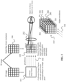
- FIG. 1 shows a device 100 according to an embodiment of the invention.
- the device 100 is particularly configured to display a 3D image.
- the 3D image to be displayed may be received by the device 100, e.g., by an input video steam.
- any 3D image to be displayed may be rendered by the device 100 based on a 2D image and a depth map 106. These may be generated by the device 100 from the 3D image to be displayed, as explained later.
- the device 100 comprises a light source 101, a diffuser 103, and a controller 105.
- the light source 101 is configured to emit light beams 102. Each light beam 102 thereby corresponds to a pixel of a 2D image.
- the diffuser 103 is further configured to diffuse the light beams emitted from the light source 101.
- the diffuser 103 to this end includes a plurality of diffuser elements 104, which are distributed across a 3D volume. In FIG. 1 for illustrational purposes only, four diffuser elements 104 are shown.
- Each diffuser element 104 of the diffuser 103 is individually controllable to be transmissive or diffusive, particularly by means of the controller 105 as indicated by the respective arrows in FIG. 1 That is, the controller 105 is configured to control each diffuser element 104 to be transmissive or diffusive based on the depth map 106. This results in the creation of the 3D image.
- FIG. 2 illustrates schematically how a device 100 according to an embodiment of the invention generates the 3D image.
- FIG. 2 thereby bases on the device 100 shown in FIG. 1 , i.e. same elements are labelled with the same reference signs and function likewise.
- FIG. 2 shows that the 3D image to be displayed can be represented by a 2D image and a depth map 106.
- the diffuser 103 with its individually controllable diffuser elements 104 can be controlled to generate the 3D image based on the 2D image and the depth map 106.
- the depth map 106 usually has a lower resolution than the 2D image.
- a collimated image engine may be used as the light source 101. It takes the 2D image as an input, and is accordingly configured to output a set of narrow light beams 102, wherein each light beam 102 corresponds to an image pixel of the 2D image.
- the diffuser 103 takes these narrow light beams 102, i.e. the light beams 102 impinge on the diffuser 103 which is configured to diffuse them based on the depth map 106, i.e. as shown in FIG. 1 by the controller 105 receiving the depth map 106 as an input.
- the diffuser 103 includes the plurality of individually controllable diffuser elements 104, which are distributed across a 3D volume.
- the diffuser elements 104 are arranged in a plurality of layers, wherein each layer 200 may be associated with a different depth in the 3D image.
- the shown layers 200 are particularly arranged one after the other in direction of the light beams 102 and are spaced apart from each other.
- the diffuser elements 104 in each layer 200 adjoin each other.
- each column 201 comprises diffuser elements 104 located in different layers 200.
- a certain diffuser element 104 may be switched on. When a diffuser element 104 is switched on, it will diffuse the incoming narrow light beam 102 before it is projected directly to the eye (pupil).
- the controller 105 may particularly be configured to select, for each column 201, one layer 200 based on the depth map 106 and to control the one diffuser element 104 of the column 201 which is located in the selected layer 200 to be diffusive and to control the one or more diffuser elements 104 of the column 201 which are located in the one or more non-selected layers 200 to be transmissive.
- the selected diffuser elements 104 of the diffuser 103 may correspond to an estimated depth of the pixels. As also illustrated in FIG. 2 , when the eye is focusing on an object 1 in the image, an object 2 is naturally out of focus.
- FIG. 2 also shows that a magnifier 202, e.g., a lens, can be arranged on an exit side of the diffuser 103.
- the magnifier 202 allows a user to view an enlarged 3D image.
- the controller 105 of the device 100 is configured to decompose the 3D image to be displayed (e.g., as received) into the 2D image and the depth map 106. Then, the controller 105 can control the light source 101 based on the 2D image, and can control the diffuser 103 based on the depth map 106.
- the controller 105 may also be configured to calculate a predicted depth map for a next 3D image based on the depth map 106, and to obtain a depth estimate of the next 3D image based on the predicted depth map. An example implementation thereof is shown in FIG. 4 .
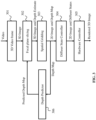
- FIG. 3 shows particularly a block diagram for processing an incoming video stream containing a sequence of 3D images to be displayed.
- the processing shown in FIG. 3 may be carried out by the controller 105 (which receives the video stream).
- the video stream may accordingly be fed into the device 100 of FIG. 1 .
- a block 301 "3D Video Frame” extracts a 3D Image from the video stream and feeds it to the block 302 "Focal Plane Slicing".
- Block 302 estimates the depth of the current image (or the number of focal planes (depths) present in the current 3D image).
- the 3D image and the depth estimate are forwarded to block 303 "Spatial Gridding", which decomposes the 3D image into a 2D image and a depth map 106.
- the next block 304 "Diffuser State Controller” takes the depth map 106 to select the diffusing layer state to be assigned to each pixel, and it forwards the 2D image data.
- both the 2D image and a set of diffusing layer states are used by block 305 "Hardware Controller", which may be implemented by the controller 105, in order to render the 3D image.
- a "Depth Predictor” may be applied in block 306, in order to predict the depth distribution of the next 3D image.
- the different blocks may represent different functional steps, which the controller 105 is able to implement.
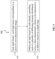
- FIG. 4 shows a method 400 according to an embodiment of the invention.
- the method 400 may be performed by a device for displaying a 3D image, particularly by the device 100 shown in FIG. 1 (and schematically explained in FIG. 2 ).
- the method 400 is usable for displaying a 3D image.
- the method 400 comprises a step 401 of emitting light beams 102, each light beam 102 corresponding to a pixel of a 2D image.
- the method 400 comprises a step 402 of diffusing the light beams 102 by individually controlling each of a plurality of diffusing elements 104 distributed across a 3D volume to be transmissive or diffusive based on a depth map 106.
Landscapes
- Physics & Mathematics (AREA)
- General Physics & Mathematics (AREA)
- Optics & Photonics (AREA)
- Engineering & Computer Science (AREA)
- Multimedia (AREA)
- Signal Processing (AREA)
- Testing, Inspecting, Measuring Of Stereoscopic Televisions And Televisions (AREA)
Claims (14)
- Vorrichtung (100) zum Anzeigen von dreidimensionalen (three-dimensional, 3D) Bildern, wobei die Vorrichtung (100) Folgendes umfasst:eine Lichtquelle (101), die dazu konfiguriert ist, Lichtstrahlen (102) zu emittieren, wobei jeder Lichtstrahl (102) einem Pixel von zweidimensionalen (2D) Bildern entspricht, undeinen Streuer (103), der dazu konfiguriert ist, die Lichtstrahlen (102) zu streuen,wobei der Streuer (103) eine Vielzahl von Streuelementen (104) beinhaltet, die über ein dreidimensionales Volumen verteilt ist, und jedes Streuelement (104) individuell steuerbar ist, um durchlässig oder streuend zu sein, undeine Steuerung (105), die zu Folgendem konfiguriert ist:Zerlegen (303) von 3D-Bildern in 2D-Bilder und eine Tiefenkarte (106),Steuern der Lichtquelle (101) basierend auf den 2D-Bildern,Steuern jedes Streuelements (104) dazu, basierend auf der Tiefenkarte (106) durchlässig oder streuend zu sein.
- Vorrichtung (100) gemäß Anspruch 1, wobei die Streuelemente (104) in einer Vielzahl von Schichten (200) angeordnet sind.
- Vorrichtung (100) gemäß Anspruch 2, wobei die Streuelemente (104) in Spalten (201) angeordnet sind, wobei jede Spalte (201) Streuelemente (104) umfasst, die sich in verschiedenen Schichten (200) befinden.
- Vorrichtung (100) gemäß Anspruch 3, wobei die Steuerung (105) dazu konfiguriert ist, für jede Spalte (201) eine Schicht (200) basierend auf der Tiefenkarte (106) auszuwählen und das eine Streuelement (104) der Spalte (201), das sich in der ausgewählten Schicht (200) befindet, derart zu steuern, um streuend zu sein, und das eine oder die mehreren Streuelemente (104) der Spalte (201), die sich in der einen oder den mehreren nicht ausgewählten Schichten (200) befinden, derart zu steuern, um durchlässig zu sein.
- Vorrichtung (100) gemäß einem der Ansprüche 2 bis 4, wobei die Streuelemente (104) in jeder Schicht (200) aneinander angrenzen.
- Vorrichtung (100) gemäß einem der Ansprüche 2 bis 5, wobei die Schichten (200) voneinander beabstandet sind.
- Vorrichtung (100) gemäß einem der Ansprüche 3 bis 6, wobei eine Spalte (201) pro Pixel vorliegt,
oder wobei eine Spalte (201) pro Pixelgruppe vorliegt, wobei jede Gruppe mehrere Pixel umfasst. - Vorrichtung (100) gemäß einem der Ansprüche 2 bis 7, wobei jede Schicht (200) mit einer verschiedenen Tiefenkarte in den 3D-Bildern verknüpft ist.
- Vorrichtung (100) gemäß einem der Ansprüche 1 bis 8, wobei die Tiefenkarte (106) eine niedrigere Auflösung als die 2D-Bilder aufweist.
- Vorrichtung (100) gemäß einem der Ansprüche 1 bis 9, wobei die Steuerung (105) ferner dazu konfiguriert ist, eine vorhergesagte Tiefenkarte für nächste 3D-Bilder basierend auf der Tiefenkarte (106) zu berechnen (306) und eine Tiefenschätzung der nächsten 3D-Bilder basierend auf der vorhergesagten Tiefenkarte zu erlangen (302).
- Vorrichtung (100) gemäß einem der Ansprüche 1 bis 10, ferner umfassend eine Lupe (202), die an einer Ausgangsseite des Streuers (103) angeordnet ist.
- Vorrichtung (100) gemäß Anspruch 11, wobei die Lupe (200) eine Brennebene aufweist und der Streuer (103) eine Vielzahl von Streuschichten umfasst, wobei die Streuschichten Folgendes beinhalten:eine erste Streuschicht, die sich in der Brennebene befindet oder sich zwischen der Brennebene und der Lupe (200) befindet, undeine oder mehrere weitere Streuschichten, die sich zwischen der ersten Streuschicht und der Lupe (200) befinden.
- Verfahren (400) zum Anzeigen von dreidimensionalen (3D) Bildern, wobei das Verfahren (400) Folgendes umfasstZerlegen von 3D-Bildern in zweidimensionale, 2D, Bilder und eine Tiefenkarte (106),Emittieren (401) von Lichtstrahlen (102), wobei jeder Lichtstrahl (102) einem Pixel von 2D-Bildern entspricht,Streuen (402) der Lichtstrahlen (102) durch individuelles Steuern jedes einer Vielzahl von Streuelementen (104), die über ein dreidimensionales Volumen verteilt ist, um durchlässig oder streuend zu sein, basierend auf der Tiefenkarte (106).
- Computerprogrammprodukt, umfassend einen Programmcode zum Steuern einer Vorrichtung (100) gemäß einem der Ansprüche 1 bis 12 oder zum Durchführen eines Verfahrens (400) gemäß Anspruch 13, wenn der Programmcode auf einem Computer ausgeführt wird.
Applications Claiming Priority (1)
| Application Number | Priority Date | Filing Date | Title |
|---|---|---|---|
| PCT/EP2018/067708 WO2020001792A1 (en) | 2018-06-29 | 2018-06-29 | Device and method for displaying a 3d image |
Publications (2)
| Publication Number | Publication Date |
|---|---|
| EP3797332A1 EP3797332A1 (de) | 2021-03-31 |
| EP3797332B1 true EP3797332B1 (de) | 2025-05-21 |
Family
ID=62846171
Family Applications (1)
| Application Number | Title | Priority Date | Filing Date |
|---|---|---|---|
| EP18738250.2A Active EP3797332B1 (de) | 2018-06-29 | 2018-06-29 | Vorrichtung und verfahren zur anzeige von 3d-bildern |
Country Status (4)
| Country | Link |
|---|---|
| US (1) | US20210120228A1 (de) |
| EP (1) | EP3797332B1 (de) |
| CN (1) | CN112352189B (de) |
| WO (1) | WO2020001792A1 (de) |
Citations (2)
| Publication number | Priority date | Publication date | Assignee | Title |
|---|---|---|---|---|
| US5113272A (en) * | 1990-02-12 | 1992-05-12 | Raychem Corporation | Three dimensional semiconductor display using liquid crystal |
| US20020130820A1 (en) * | 1998-04-20 | 2002-09-19 | Alan Sullivan | Multi-planar volumetric display system and method of operation |
Family Cites Families (9)
| Publication number | Priority date | Publication date | Assignee | Title |
|---|---|---|---|---|
| US6940645B2 (en) * | 2003-04-22 | 2005-09-06 | Eastman Kodak Company | Monocentric autostereoscopic optical apparatus with a spherical gradient-index ball lens |
| US7703924B2 (en) * | 2004-10-25 | 2010-04-27 | The Trustees Of Columbia University In The City Of New York | Systems and methods for displaying three-dimensional images |
| CN101770738A (zh) * | 2009-01-04 | 2010-07-07 | 朗讯科技公司 | 3d显示设备和方法 |
| KR102171307B1 (ko) * | 2013-12-19 | 2020-10-28 | 삼성전자주식회사 | 입체 영상 디스플레이 장치 및 그 제조 방법 |
| CN106461955B (zh) * | 2014-01-31 | 2019-08-13 | 奇跃公司 | 显示增强现实的方法 |
| US9866822B1 (en) * | 2015-05-18 | 2018-01-09 | Rockwell Collins, Inc. | Three dimensional displays |
| CN106873169A (zh) * | 2015-12-10 | 2017-06-20 | 上海交通大学 | 三维显示器 |
| AU2017244109B2 (en) * | 2016-03-31 | 2022-06-23 | Magic Leap, Inc. | Interactions with 3D virtual objects using poses and multiple-DOF controllers |
| US10366642B2 (en) * | 2016-12-01 | 2019-07-30 | Disney Enterprises, Inc. | Interactive multiplane display system with transparent transmissive layers |
-
2018
- 2018-06-29 CN CN201880095119.8A patent/CN112352189B/zh active Active
- 2018-06-29 EP EP18738250.2A patent/EP3797332B1/de active Active
- 2018-06-29 WO PCT/EP2018/067708 patent/WO2020001792A1/en not_active Ceased
-
2020
- 2020-12-29 US US17/136,958 patent/US20210120228A1/en not_active Abandoned
Patent Citations (2)
| Publication number | Priority date | Publication date | Assignee | Title |
|---|---|---|---|---|
| US5113272A (en) * | 1990-02-12 | 1992-05-12 | Raychem Corporation | Three dimensional semiconductor display using liquid crystal |
| US20020130820A1 (en) * | 1998-04-20 | 2002-09-19 | Alan Sullivan | Multi-planar volumetric display system and method of operation |
Also Published As
| Publication number | Publication date |
|---|---|
| EP3797332A1 (de) | 2021-03-31 |
| CN112352189A (zh) | 2021-02-09 |
| WO2020001792A1 (en) | 2020-01-02 |
| US20210120228A1 (en) | 2021-04-22 |
| CN112352189B (zh) | 2022-07-22 |
Similar Documents
| Publication | Publication Date | Title |
|---|---|---|
| JP3269823B2 (ja) | 情報の2次元および3次元表示のための光学システム | |
| US9182604B2 (en) | Minimized-thickness angular scanner of electromagnetic radiation | |
| US5781229A (en) | Multi-viewer three dimensional (3-D) virtual display system and operating method therefor | |
| KR101502603B1 (ko) | 입체 영상 표시 장치 및 그 방법 | |
| EP2854402B1 (de) | Mehrfachbildanzeigevorrichtung und Steuerverfahren dafür | |
| JP4724186B2 (ja) | スイートスポットを追跡する方法及び装置 | |
| US20100171811A1 (en) | Method and device for the creation of pseudo-holographic images | |
| US11831860B2 (en) | Displaying device, device and method for generating data, and displaying system | |
| JP2005500578A (ja) | 3次元アンチエリアシングを用いた多平面ボリュメトリック表示システムおよびその動作方法 | |
| SE500061C2 (sv) | Presentationsanordning | |
| WO2006068426A1 (en) | Parallax-barrier type stereoscopic display apparatus | |
| KR101975246B1 (ko) | 다시점 영상 디스플레이 장치 및 그 제어 방법 | |
| Liu et al. | Super multi-view near-eye 3D display with enlarged field of view | |
| EP3797332B1 (de) | Vorrichtung und verfahren zur anzeige von 3d-bildern | |
| US20040178969A1 (en) | Spatial three-dimensional image display device | |
| Li et al. | Programmable plenoptic function for high-quality directional backlight autostereoscopy | |
| CN114355624A (zh) | 一种显示装置和系统以及方法 | |
| US6195069B1 (en) | Method and apparatus for 3-dimensional motion picture display | |
| Hua | Advances in Head‐Mounted Light‐Field Displays for Virtual and Augmented Reality | |
| Lipton | Future of autostereoscopic electronic displays | |
| Park et al. | Augmented reality lightfield display for a smart window using an active pinhole array | |
| Liu et al. | 68‐3: Naked Eye Three‐dimensional Display System Based on Time‐multiplexed Technology | |
| Li et al. | 68‐2: View‐Dependent Light‐Field Display that Supports Accommodation Using a Commercially‐Available High Pixel Density LCD Panel | |
| JP3454793B2 (ja) | 三次元映像表示装置への供給映像生成方法 | |
| RU2158949C1 (ru) | Способ воспроизведения изображения объекта |
Legal Events
| Date | Code | Title | Description |
|---|---|---|---|
| STAA | Information on the status of an ep patent application or granted ep patent |
Free format text: STATUS: UNKNOWN |
|
| STAA | Information on the status of an ep patent application or granted ep patent |
Free format text: STATUS: THE INTERNATIONAL PUBLICATION HAS BEEN MADE |
|
| PUAI | Public reference made under article 153(3) epc to a published international application that has entered the european phase |
Free format text: ORIGINAL CODE: 0009012 |
|
| STAA | Information on the status of an ep patent application or granted ep patent |
Free format text: STATUS: REQUEST FOR EXAMINATION WAS MADE |
|
| 17P | Request for examination filed |
Effective date: 20201222 |
|
| AK | Designated contracting states |
Kind code of ref document: A1 Designated state(s): AL AT BE BG CH CY CZ DE DK EE ES FI FR GB GR HR HU IE IS IT LI LT LU LV MC MK MT NL NO PL PT RO RS SE SI SK SM TR |
|
| AX | Request for extension of the european patent |
Extension state: BA ME |
|
| DAV | Request for validation of the european patent (deleted) | ||
| DAX | Request for extension of the european patent (deleted) | ||
| STAA | Information on the status of an ep patent application or granted ep patent |
Free format text: STATUS: EXAMINATION IS IN PROGRESS |
|
| 17Q | First examination report despatched |
Effective date: 20221121 |
|
| REG | Reference to a national code |
Free format text: PREVIOUS MAIN CLASS: G02B0027020000 Ref country code: DE Ref legal event code: R079 Ref document number: 602018082088 Country of ref document: DE Free format text: PREVIOUS MAIN CLASS: G02B0027020000 Ipc: G02B0030520000 |
|
| GRAP | Despatch of communication of intention to grant a patent |
Free format text: ORIGINAL CODE: EPIDOSNIGR1 |
|
| STAA | Information on the status of an ep patent application or granted ep patent |
Free format text: STATUS: GRANT OF PATENT IS INTENDED |
|
| RIC1 | Information provided on ipc code assigned before grant |
Ipc: H04N 13/395 20180101ALI20241202BHEP Ipc: G02B 27/01 20060101ALI20241202BHEP Ipc: G02B 30/52 20200101AFI20241202BHEP |
|
| INTG | Intention to grant announced |
Effective date: 20241216 |
|
| GRAS | Grant fee paid |
Free format text: ORIGINAL CODE: EPIDOSNIGR3 |
|
| GRAA | (expected) grant |
Free format text: ORIGINAL CODE: 0009210 |
|
| STAA | Information on the status of an ep patent application or granted ep patent |
Free format text: STATUS: THE PATENT HAS BEEN GRANTED |
|
| AK | Designated contracting states |
Kind code of ref document: B1 Designated state(s): AL AT BE BG CH CY CZ DE DK EE ES FI FR GB GR HR HU IE IS IT LI LT LU LV MC MK MT NL NO PL PT RO RS SE SI SK SM TR |
|
| REG | Reference to a national code |
Ref country code: GB Ref legal event code: FG4D |
|
| REG | Reference to a national code |
Ref country code: CH Ref legal event code: EP |
|
| REG | Reference to a national code |
Ref country code: DE Ref legal event code: R096 Ref document number: 602018082088 Country of ref document: DE |
|
| REG | Reference to a national code |
Ref country code: IE Ref legal event code: FG4D |
|
| PGFP | Annual fee paid to national office [announced via postgrant information from national office to epo] |
Ref country code: DE Payment date: 20250507 Year of fee payment: 8 |
|
| REG | Reference to a national code |
Ref country code: NL Ref legal event code: MP Effective date: 20250521 |
|
| PG25 | Lapsed in a contracting state [announced via postgrant information from national office to epo] |
Ref country code: PT Free format text: LAPSE BECAUSE OF FAILURE TO SUBMIT A TRANSLATION OF THE DESCRIPTION OR TO PAY THE FEE WITHIN THE PRESCRIBED TIME-LIMIT Effective date: 20250922 Ref country code: FI Free format text: LAPSE BECAUSE OF FAILURE TO SUBMIT A TRANSLATION OF THE DESCRIPTION OR TO PAY THE FEE WITHIN THE PRESCRIBED TIME-LIMIT Effective date: 20250521 Ref country code: ES Free format text: LAPSE BECAUSE OF FAILURE TO SUBMIT A TRANSLATION OF THE DESCRIPTION OR TO PAY THE FEE WITHIN THE PRESCRIBED TIME-LIMIT Effective date: 20250521 |
|
| REG | Reference to a national code |
Ref country code: LT Ref legal event code: MG9D |
|
| PG25 | Lapsed in a contracting state [announced via postgrant information from national office to epo] |
Ref country code: NO Free format text: LAPSE BECAUSE OF FAILURE TO SUBMIT A TRANSLATION OF THE DESCRIPTION OR TO PAY THE FEE WITHIN THE PRESCRIBED TIME-LIMIT Effective date: 20250821 Ref country code: GR Free format text: LAPSE BECAUSE OF FAILURE TO SUBMIT A TRANSLATION OF THE DESCRIPTION OR TO PAY THE FEE WITHIN THE PRESCRIBED TIME-LIMIT Effective date: 20250822 |
|
| PG25 | Lapsed in a contracting state [announced via postgrant information from national office to epo] |
Ref country code: PL Free format text: LAPSE BECAUSE OF FAILURE TO SUBMIT A TRANSLATION OF THE DESCRIPTION OR TO PAY THE FEE WITHIN THE PRESCRIBED TIME-LIMIT Effective date: 20250521 Ref country code: NL Free format text: LAPSE BECAUSE OF FAILURE TO SUBMIT A TRANSLATION OF THE DESCRIPTION OR TO PAY THE FEE WITHIN THE PRESCRIBED TIME-LIMIT Effective date: 20250521 |
|
| PG25 | Lapsed in a contracting state [announced via postgrant information from national office to epo] |
Ref country code: BG Free format text: LAPSE BECAUSE OF FAILURE TO SUBMIT A TRANSLATION OF THE DESCRIPTION OR TO PAY THE FEE WITHIN THE PRESCRIBED TIME-LIMIT Effective date: 20250521 |
|
| PG25 | Lapsed in a contracting state [announced via postgrant information from national office to epo] |
Ref country code: HR Free format text: LAPSE BECAUSE OF FAILURE TO SUBMIT A TRANSLATION OF THE DESCRIPTION OR TO PAY THE FEE WITHIN THE PRESCRIBED TIME-LIMIT Effective date: 20250521 |
|
| PG25 | Lapsed in a contracting state [announced via postgrant information from national office to epo] |
Ref country code: RS Free format text: LAPSE BECAUSE OF FAILURE TO SUBMIT A TRANSLATION OF THE DESCRIPTION OR TO PAY THE FEE WITHIN THE PRESCRIBED TIME-LIMIT Effective date: 20250821 |
|
| PG25 | Lapsed in a contracting state [announced via postgrant information from national office to epo] |
Ref country code: IS Free format text: LAPSE BECAUSE OF FAILURE TO SUBMIT A TRANSLATION OF THE DESCRIPTION OR TO PAY THE FEE WITHIN THE PRESCRIBED TIME-LIMIT Effective date: 20250921 |
|
| PG25 | Lapsed in a contracting state [announced via postgrant information from national office to epo] |
Ref country code: LV Free format text: LAPSE BECAUSE OF FAILURE TO SUBMIT A TRANSLATION OF THE DESCRIPTION OR TO PAY THE FEE WITHIN THE PRESCRIBED TIME-LIMIT Effective date: 20250521 |
|
| REG | Reference to a national code |
Ref country code: AT Ref legal event code: MK05 Ref document number: 1797230 Country of ref document: AT Kind code of ref document: T Effective date: 20250521 |
|
| PG25 | Lapsed in a contracting state [announced via postgrant information from national office to epo] |
Ref country code: AT Free format text: LAPSE BECAUSE OF FAILURE TO SUBMIT A TRANSLATION OF THE DESCRIPTION OR TO PAY THE FEE WITHIN THE PRESCRIBED TIME-LIMIT Effective date: 20250521 Ref country code: DK Free format text: LAPSE BECAUSE OF FAILURE TO SUBMIT A TRANSLATION OF THE DESCRIPTION OR TO PAY THE FEE WITHIN THE PRESCRIBED TIME-LIMIT Effective date: 20250521 Ref country code: SM Free format text: LAPSE BECAUSE OF FAILURE TO SUBMIT A TRANSLATION OF THE DESCRIPTION OR TO PAY THE FEE WITHIN THE PRESCRIBED TIME-LIMIT Effective date: 20250521 |
|
| PG25 | Lapsed in a contracting state [announced via postgrant information from national office to epo] |
Ref country code: CZ Free format text: LAPSE BECAUSE OF FAILURE TO SUBMIT A TRANSLATION OF THE DESCRIPTION OR TO PAY THE FEE WITHIN THE PRESCRIBED TIME-LIMIT Effective date: 20250521 |
|
| PG25 | Lapsed in a contracting state [announced via postgrant information from national office to epo] |
Ref country code: EE Free format text: LAPSE BECAUSE OF FAILURE TO SUBMIT A TRANSLATION OF THE DESCRIPTION OR TO PAY THE FEE WITHIN THE PRESCRIBED TIME-LIMIT Effective date: 20250521 |
|
| PG25 | Lapsed in a contracting state [announced via postgrant information from national office to epo] |
Ref country code: SK Free format text: LAPSE BECAUSE OF FAILURE TO SUBMIT A TRANSLATION OF THE DESCRIPTION OR TO PAY THE FEE WITHIN THE PRESCRIBED TIME-LIMIT Effective date: 20250521 Ref country code: RO Free format text: LAPSE BECAUSE OF FAILURE TO SUBMIT A TRANSLATION OF THE DESCRIPTION OR TO PAY THE FEE WITHIN THE PRESCRIBED TIME-LIMIT Effective date: 20250521 |
|
| REG | Reference to a national code |
Ref country code: CH Ref legal event code: H13 Free format text: ST27 STATUS EVENT CODE: U-0-0-H10-H13 (AS PROVIDED BY THE NATIONAL OFFICE) Effective date: 20260127 |
|
| PG25 | Lapsed in a contracting state [announced via postgrant information from national office to epo] |
Ref country code: IT Free format text: LAPSE BECAUSE OF FAILURE TO SUBMIT A TRANSLATION OF THE DESCRIPTION OR TO PAY THE FEE WITHIN THE PRESCRIBED TIME-LIMIT Effective date: 20250521 |
|
| PG25 | Lapsed in a contracting state [announced via postgrant information from national office to epo] |
Ref country code: LU Free format text: LAPSE BECAUSE OF NON-PAYMENT OF DUE FEES Effective date: 20250629 |
|
| PG25 | Lapsed in a contracting state [announced via postgrant information from national office to epo] |
Ref country code: MC Free format text: LAPSE BECAUSE OF FAILURE TO SUBMIT A TRANSLATION OF THE DESCRIPTION OR TO PAY THE FEE WITHIN THE PRESCRIBED TIME-LIMIT Effective date: 20250521 |
|
| REG | Reference to a national code |
Ref country code: BE Ref legal event code: MM Effective date: 20250630 |
|
| PLBE | No opposition filed within time limit |
Free format text: ORIGINAL CODE: 0009261 |
|
| STAA | Information on the status of an ep patent application or granted ep patent |
Free format text: STATUS: NO OPPOSITION FILED WITHIN TIME LIMIT |