EP3796092A1 - Image forming apparatus - Google Patents
Image forming apparatus Download PDFInfo
- Publication number
- EP3796092A1 EP3796092A1 EP20195627.3A EP20195627A EP3796092A1 EP 3796092 A1 EP3796092 A1 EP 3796092A1 EP 20195627 A EP20195627 A EP 20195627A EP 3796092 A1 EP3796092 A1 EP 3796092A1
- Authority
- EP
- European Patent Office
- Prior art keywords
- collection
- attachment part
- main body
- disposed
- image forming
- Prior art date
- Legal status (The legal status is an assumption and is not a legal conclusion. Google has not performed a legal analysis and makes no representation as to the accuracy of the status listed.)
- Granted
Links
- 239000002699 waste material Substances 0.000 claims abstract description 71
- 238000006073 displacement reaction Methods 0.000 claims abstract description 36
- 238000009825 accumulation Methods 0.000 claims abstract description 19
- 230000004044 response Effects 0.000 claims abstract description 10
- 230000005540 biological transmission Effects 0.000 claims description 44
- 238000004891 communication Methods 0.000 claims description 20
- 230000005684 electric field Effects 0.000 claims description 5
- 230000015572 biosynthetic process Effects 0.000 claims description 2
- 238000004140 cleaning Methods 0.000 description 34
- 238000003860 storage Methods 0.000 description 15
- 238000001514 detection method Methods 0.000 description 12
- 238000011161 development Methods 0.000 description 8
- 238000005498 polishing Methods 0.000 description 8
- 229920003002 synthetic resin Polymers 0.000 description 4
- 239000000057 synthetic resin Substances 0.000 description 4
- 230000007246 mechanism Effects 0.000 description 3
- 238000000034 method Methods 0.000 description 3
- 230000003287 optical effect Effects 0.000 description 3
- 230000008569 process Effects 0.000 description 3
- 230000003068 static effect Effects 0.000 description 3
- 238000005513 bias potential Methods 0.000 description 2
- 239000003086 colorant Substances 0.000 description 2
- 230000003247 decreasing effect Effects 0.000 description 2
- 230000006870 function Effects 0.000 description 2
- 238000003780 insertion Methods 0.000 description 2
- 230000037431 insertion Effects 0.000 description 2
- 238000004519 manufacturing process Methods 0.000 description 2
- 239000007769 metal material Substances 0.000 description 2
- 229920000139 polyethylene terephthalate Polymers 0.000 description 2
- 239000005020 polyethylene terephthalate Substances 0.000 description 2
- 238000012545 processing Methods 0.000 description 2
- 229910001220 stainless steel Inorganic materials 0.000 description 2
- 239000010935 stainless steel Substances 0.000 description 2
- 238000011144 upstream manufacturing Methods 0.000 description 2
- 230000000694 effects Effects 0.000 description 1
- 239000000463 material Substances 0.000 description 1
- 239000002184 metal Substances 0.000 description 1
- 230000002093 peripheral effect Effects 0.000 description 1
- -1 polyethylene terephthalate Polymers 0.000 description 1
- 229920005989 resin Polymers 0.000 description 1
- 239000011347 resin Substances 0.000 description 1
- 238000005070 sampling Methods 0.000 description 1
Images


Classifications
-
- G—PHYSICS
- G03—PHOTOGRAPHY; CINEMATOGRAPHY; ANALOGOUS TECHNIQUES USING WAVES OTHER THAN OPTICAL WAVES; ELECTROGRAPHY; HOLOGRAPHY
- G03G—ELECTROGRAPHY; ELECTROPHOTOGRAPHY; MAGNETOGRAPHY
- G03G21/00—Arrangements not provided for by groups G03G13/00 - G03G19/00, e.g. cleaning, elimination of residual charge
- G03G21/10—Collecting or recycling waste developer
- G03G21/12—Toner waste containers
-
- G—PHYSICS
- G03—PHOTOGRAPHY; CINEMATOGRAPHY; ANALOGOUS TECHNIQUES USING WAVES OTHER THAN OPTICAL WAVES; ELECTROGRAPHY; HOLOGRAPHY
- G03G—ELECTROGRAPHY; ELECTROPHOTOGRAPHY; MAGNETOGRAPHY
- G03G21/00—Arrangements not provided for by groups G03G13/00 - G03G19/00, e.g. cleaning, elimination of residual charge
- G03G21/0005—Arrangements not provided for by groups G03G13/00 - G03G19/00, e.g. cleaning, elimination of residual charge for removing solid developer or debris from the electrographic recording medium
-
- G—PHYSICS
- G03—PHOTOGRAPHY; CINEMATOGRAPHY; ANALOGOUS TECHNIQUES USING WAVES OTHER THAN OPTICAL WAVES; ELECTROGRAPHY; HOLOGRAPHY
- G03G—ELECTROGRAPHY; ELECTROPHOTOGRAPHY; MAGNETOGRAPHY
- G03G21/00—Arrangements not provided for by groups G03G13/00 - G03G19/00, e.g. cleaning, elimination of residual charge
- G03G21/10—Collecting or recycling waste developer
- G03G21/105—Arrangements for conveying toner waste
-
- G—PHYSICS
- G03—PHOTOGRAPHY; CINEMATOGRAPHY; ANALOGOUS TECHNIQUES USING WAVES OTHER THAN OPTICAL WAVES; ELECTROGRAPHY; HOLOGRAPHY
- G03G—ELECTROGRAPHY; ELECTROPHOTOGRAPHY; MAGNETOGRAPHY
- G03G21/00—Arrangements not provided for by groups G03G13/00 - G03G19/00, e.g. cleaning, elimination of residual charge
- G03G21/16—Mechanical means for facilitating the maintenance of the apparatus, e.g. modular arrangements
- G03G21/1604—Arrangement or disposition of the entire apparatus
- G03G21/1609—Arrangement or disposition of the entire apparatus for space saving, e.g. structural arrangements
-
- G—PHYSICS
- G03—PHOTOGRAPHY; CINEMATOGRAPHY; ANALOGOUS TECHNIQUES USING WAVES OTHER THAN OPTICAL WAVES; ELECTROGRAPHY; HOLOGRAPHY
- G03G—ELECTROGRAPHY; ELECTROPHOTOGRAPHY; MAGNETOGRAPHY
- G03G15/00—Apparatus for electrographic processes using a charge pattern
- G03G15/06—Apparatus for electrographic processes using a charge pattern for developing
- G03G15/08—Apparatus for electrographic processes using a charge pattern for developing using a solid developer, e.g. powder developer
- G03G15/0822—Arrangements for preparing, mixing, supplying or dispensing developer
- G03G15/0848—Arrangements for testing or measuring developer properties or quality, e.g. charge, size, flowability
- G03G15/0856—Detection or control means for the developer level
- G03G15/086—Detection or control means for the developer level the level being measured by electro-magnetic means
-
- G—PHYSICS
- G03—PHOTOGRAPHY; CINEMATOGRAPHY; ANALOGOUS TECHNIQUES USING WAVES OTHER THAN OPTICAL WAVES; ELECTROGRAPHY; HOLOGRAPHY
- G03G—ELECTROGRAPHY; ELECTROPHOTOGRAPHY; MAGNETOGRAPHY
- G03G15/00—Apparatus for electrographic processes using a charge pattern
- G03G15/65—Apparatus which relate to the handling of copy material
- G03G15/6502—Supplying of sheet copy material; Cassettes therefor
Definitions
- the present invention relates to an image forming apparatus.
- the image forming apparatus is provided with a cleaning device which removes a residual toner not transferred to a recording medium, from an image carrier, for example.
- the cleaning device includes a storage container in which the residual toner is stored, and first and second detection means which detect that an amount of the residual toner in the storage container reaches a predetermined amount.
- the first and second detection means include two input electrodes disposed separately from each other in the upper-and-lower direction in the storage container, one output electrode disposed between the two input electrodes, a switch switching the two input electrodes, and a detection circuit detecting an electrostatic capacity between one of the input electrodes and the output electrode which are connected to each other via the switch.
- the cleaning device because it is necessary to provide the electrodes in the storage container, there is a problem that the configuration of the storage container becomes complicated and the manufacturing cost may be increased. Additionally, because the electrodes in the storage container are necessarily connected to the detection circuit disposed outside the storage container, there is a problem that the configuration of the cleaning device becomes complicated and the manufacturing cost may be increased.
- a non-contact type electrostatic capacity sensor is disposed outside the storage container and detects an accumulation amount of the residual toner in the storage container.
- an electrostatic capacity measured by the non-contact type electrostatic capacity sensor is varied in response to a distance between the electrostatic capacity sensor and an object to be detected. Then, if a member disposed near the electrostatic capacity sensor is displaced, the electrostatic capacity sensor does not allow detecting an accurate electrostatic capacity. Thus, when the electrostatic capacity sensor is disposed near a movable member, it becomes impossible to detect an accurate accumulation amount of the residual toner.
- the storage container is often disposed below an image carrier, which is a source for the residual toner, that is, in the lower portion in the image forming apparatus because it receives the falling residual toner. Additionally, in the lower portion in the image forming apparatus, a sheet feeding cassette in which a recording material (a sheet) is stored is often attached detachably. Then, if the storage container is disposed near the attachable and detachable sheet feeding cassette, the non-contact type electrostatic capacity sensor may not detect an accurate accumulation amount of the residual toner in the storage container.
- a sheet feeding cassette storing the sheet is detachably attached.
- the collection side attachment part is disposed adjacent to the cassette attachment part.
- a collection container storing a waste toner discharged without transferred on the sheet is detachably attached.
- the cassette attachment part includes a cassette rail which supports the sheet feeding cassette slidably and a rail holding member which holds the cassette rail.
- the collection side attachment part includes a displacement sensor which is disposed so as to face the collection container and detects an electrostatic capacity varying in response to an accumulation amount of the waste toner stored in the collection container.
- the rail holding member is disposed so as to face at least a part of the displacement sensor.
- FIG. 1 is a front view schematically showing an inner structure of the image forming apparatus 1.
- FIG. 2 is a plan view showing a sheet feeding cassette 3, a waste toner collection device 13 and the others.
- FIG. 3 is a front view showing the sheet feeding cassette 3, the waste toner collection device 13 and the others.
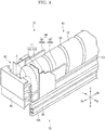
- FIG. 4 is a perspective view showing the front portion of the sheet feeding device 3 and its periphery.
- the image forming apparatus 1 is a color printer 1 performing an image forming by transferring a full color toner image formed by an electrophotographic manner on a sheet S.
- the image forming apparatus 1 includes an apparatus main body 2 constituting an approximately parallelepiped outer appearance.
- a cassette attachment part 10 to which a sheet feeding cassette 3 is attached is provided in the lower portion of the apparatus main body 2.
- the sheet feeding cassette 3 stores a paper sheet S (or a bundle of sheets S), for example.
- a discharge tray 3 on which the sheet S with the formed image is received is provided on the upper face of the apparatus main body 2.
- the sheet S is not limited to the paper sheet, and may be a resin film or a sheet for OHP.
- the cassette attachment part 10 has a space in which the sheet feeding cassette 3 is attached. On the lower portion of the front face of the apparatus main body 2, a front opening is formed, through which the sheet feeding cassette 3 is attached and detached to and from the cassette attachment part 10.
- the sheet feeding cassette 3 is formed into an approximately parallelepiped shape (a box-like shape) whose upper face is opened. The sheet feeding cassette 3 is detachably attached to the cassette attachment part 10.
- a pair of slide guides 3A is fixed, and on both the left and right sides of the cassette attachment part 10, a pair of cassette rails 10A is provided (the left side is only shown in FIG. 2 to FIG. 4 .
- the slide guide 3A and the cassette rail 10A are made of metal material, such as stainless steel, for example.
- the pair of cassette rails 10A holds the pair of slide guides 3A slidably. Thereby, the pair of cassette rails 10A supports the sheet feeding cassette 3 via the pair of slide guides 3A slidably.
- a pair of rail holding members 11 holding the pair of cassette rails 10A is provided (the left side is only shown in FIG. 2 to FIG. 4 ).
- the rail holding member 11 is made of metal material, such as stainless steel, for example.
- the rail holding member 11 is disposed in the front portion (a portion closer to the front side than the center in the front-and-rear direction) of the cassette attachment part 10.
- the rail holding member 11 has a holding main body 11A provided with an upright posture along the front-and-rear direction and a front face part 11B bent outward from the upper portion of the front end of the holding main body 11A, and forms into an almost L-shape on a plane.
- the cassette rail 10A is fixed to the holding main body 11A of the rail holding member 11, and the holding main body 11A is fixed to the apparatus main body 2.
- the lower edge of the front face part 11B is formed into an arc-shape.
- the image forming apparatus 1 is provided with a sheet feeding part 5, an image forming part 6, a fixing device 7, a toner replenishment device 12 and a waste toner collection device 13 which are stored in the apparatus main body 2.
- the sheet feeding part 5 is provided at the upstream end portion of a conveyance path 8 extending from the sheet feeding cassette 3 to the discharge tray 4.
- the fixing device 7 is provided on the downstream portion of the conveyance path 8, and the image forming part 6 is provided on the conveyance path 8 between the sheet feeding device 5 and the fixing device 7.
- the toner replenishment device 12 is disposed above the image forming part 6.
- the waste toner collection device 13 is disposed below the image forming part 6.
- the image forming part 6 includes an intermediate transferring unit 14, four drum units 15 and an optical scanning device 16.
- the intermediate transferring unit 14 is disposed below the discharge tray 4.
- the four drum units 15 are disposed below the intermediate transferring unit 14 side by side in the left-and-right direction.
- the optical scanning device 16 is disposed below the drum units 15.
- the intermediate transferring unit 14 includes an intermediate transferring belt 21 wound around a drive roller 20A disposed in the right portion in the apparatus main body 2 and a driven roller 20B disposed in the left portion in the apparatus main body 2.
- the drive roller 20A is driven by a motor (not shown) to be rotated
- the intermediate transferring belt 21 is cicurated in a left direction (refer to the arrow in FIG. 1 ).
- the belt cleaning device 22 is disposed on a left side of the driven roller 20B.
- the four drum units 15 are provided corresponding to the toners of four colors.
- Each drum unit 15 includes a photosensitive drum 23, a charging device 24, a development device 25, a primary transferring roller 26, a drum cleaning device 27 and a static eliminator 28.
- the four drum units 15 have the same configuration, and one of the drum units 15 will be described in the following description.
- the photosensitive drum 23 is driven by a motor (not shown) to be rotated while coming into contact with the lower surface of the intermediate transferring belt 21.
- the charging device 24, the development device 25, the primary transferring roller 26, the drum cleaning device 27 and the static eliminator 28 are disposed around the photosensitive drum 23 in the order of a transferring process.
- the primary transferring roller 26 is disposed so as to face the photosensitive drum 23 from the upper side across the intermediate transferring belt 21. With the right side portion of the intermediate transferring belt 21 (the drive roller 20A), a secondary transferring roller 29 comes into contact.
- the four toner bottles 31 store the toners (developers) of the four colors (yellow, magenta, cyan and black) for replenishment.
- the four tonner bottles 31 are communicated with the respective four development devices 25 through replenishment pipes (not shown) in which a screw is stored, and supplies the replenishment toner to the respective development devices 25.
- a collection bottle 61 (a collection container) is detachably attached. In the collection bottle 61, a waste toner discharged without being transferred on the sheet S is stored (collected).
- the image forming apparatus 1 is provided with a controller 17 to suitably control the devices to be controlled, such as the image forming part 6.
- the controller 17 contains a processer executing various arithmetic processing according to the program and parameter stored in a memory.
- the controller 17 performs the image forming operation based on an input image data as follows.
- the charging device 24 charges the surface of the photosensitive drum 23.
- the optical scanning unit 16 exposes the photosensitive drum 23 based on the image data to form an electrostatic latent image on the surface of the photosensitive drum 23.
- the development device 25 develops the electrostatic latent image on the photosensitive drum 23 into a toner image by using the toner supplied from the toner bottle 31 of the toner replenishment device 12.
- the four colored toner images carried on the surface of the photosensitive drum 23 are primarily transferred on the intermediate transferring belt 21 in order by the primary transferring rollers 26 applied with a primary transferring bias potential. Thereby, a full color toner image is formed on the surface of the intermediate transferring belt 21.
- the sheet feeding part 5 feeds the sheet S in the sheet feeding cassette 3 to the conveyance path 8.
- Th secondary transferring roller 29 secondarily transfers the toner image on the intermediate transferring belt 21 to the sheet S passing through the intermediate transferring belt 21 and the secondary transferring roller 29.
- the fixing device 7 fixes the toner image to the sheet S using heat. Then, the sheet S is discharged on the discharge tray 4.
- the drum cleaning device 27 removes a waste toner (a residual toner) remaining on the surface of the photosensitive drum 23 after the primary transferring.
- the static eliminator 28 emits an eraser light to erase the charge remaining on the photosensitive drum 23.
- the belt cleaning device 22 removes the waste toner remaining on the surface of the intermediate transferring belt 21 after the secondary transferring.
- the waste toner removed from the photosensitive drum 23 and the intermediate transferring belt 21 is collected in the collection bottle 61 of the waste toner collection device 13.
- FIG. 5 is a perspective view showing the toner bottle 31.
- the toner replenishment device 12 is disposed above the intermediate transferring unit 14 (the development devices 25).
- the toner replenishment device 12 includes four replenishment side attachment parts 30 to which the four toner bottles 31 are detachably attached (inserted).
- Each replenishment side attachment part 30 has a space to which the toner bottle 31 is attached.
- the replenishment side attachment part 30 includes a replenishment cover (not shown) which opens and closes the front opening.
- each toner bottle 31 includes a container main body 32 and a cap 33.
- the toner bottle 31 storing the black toner is larger (has a diameter larger) than the other toner bottles 31, and the right end replenishment side attachment part 30 to which the toner bottle 31 storing the black toner is formed to have a diameter larger than the other toner bottles 31 (refer to FIG. 1 ).
- the four toner bottles 31 have the same configuration other than their diameters, and one of the toner bottles 31 will be described below. In the following description, the direction is defined based on a state where the toner bottle 31 is attached to the replenishment side attachment part 30.
- the toner may be a two-component developer containing a toner and a carrier or a one-component developer containing a magnetic toner.
- the four toner bottles 31 (the four replenishment side attachment parts 30) may have the same size (the diameter).
- the container main body 32 is made of synthetic resin such as polyethylene terephthalate (PET), and formed into an approximately cylindrical shape long in the front-and-rear direction.
- a spiral conveyance rib 34 is formed integrally with the container main body 32 so as to protrude from the outer circumferential face inward in the radial direction (toward the axial center).
- the container main body 32 and the conveyance rib 34 have almost the same thickness.
- the rear portion of the container main body 32 is formed to be narrower than the other portion, and the rear end face of the container main body 32 is opened (not shown) .
- an approximately annular transmission gear 35 is fixed to the rear portion (the narrowed portion) of the container main body 32.
- the transmission gear 35 is connected to a drive motor M via a drive force transmission mechanism (not shown) containing a shaft and a gear.
- the container main body 32 is driven by the motor M to be rotated around the axis, and the conveyance rib 34 is rotated together with the container main body 32 to apply conveyance force along the axial direction on the toner in the container main body 32.
- the conveyance rib 34 is formed integrally with the container main body 32, but not limited thereto, the conveyance rib and the container main body may be formed by separate members (the example is not shown).
- the cap 33 is disposed on a rear side of the transmission gear 35, and attached to the container main body 32 so as to cover the rear end face (the opening) of the container main body 32.
- the cap 33 supports the rear end portion (the end portion in the axial direction) of the container main body 32 so as to be rotatable around the axis.
- the cap 33 has a communication port 36 communicated with an inside of the container main body 32.
- the communication port 36 is an approximately rectangular hole formed on the lower side face of the cap 33.
- a shitter (not shown) to open and close the communication port 36 is provided so as to be slidable in the axial direction (the front-and-rear direction). In a state where the toner bottle 31 is detached from the replenishment side attachment part 30, the shutter closes the communication port 36.
- the replenishment side attachment part 30 supports the cap 33 non-rotatably and the container main body 32 rotatably. Additionally, in the state, the transmission gear 35 is coupled with the drive motor M via the drive force transmission mechanism, and the communication port 36 is communicated with the development device 25 via the replenishment pipe or the others.
- the container main body 32 When the drive motor M is driven according to a toner replenishment instruction from the controller 17, the container main body 32 is rotated around the axis together with the transmission gear 35.
- the container main body 32 (the conveyance rib 34) attached to the replenishment side attachment part 30 is rotated around the axis, and the replenishment toner stored in the container main body 32 is conveyed toward the communication port 36.
- the toner is supplied (replenished) from the communication port 36 to the development device 25 through the replenishment pipe.
- a remaining amount detection sensor (an electrostatic capacity sensor or the line) to detect an amount of the toner stored in the toner bottle 31 is provided (not shown) .
- the remaining amount detection sensor is disposed so as to face the toner bottle 31 attached to the replenishment side attachment part 30, and measures an electrostatic capacity in response to a remaining amount of the toner.
- the controller 17 determines that the toner bottle empties (or an amount of the toner is decreased) based on the detection result of the remaining amount detection sensor, and then displays a message showing the empty of the toner bottle or a message for prompting the replacement of the toner bottle 31 on a touch panel (not shown) provided in the image forming apparatus 1.
- the user grips the grip part G to pull the toner bottle 3 forward and to detach the toner bottle 31 from the replenishment side attachment part 30.
- the shutter is biased rearward by a spring (not shown) to close the communication port 36.
- FIG. 6 is a view (a sectional view on a plane) schematically showing the drum cleaning device 27, the belt cleaning device 22 and the discharge conveyance device 18.
- FIG. 7 is a sectional view taken along the line VII-VII in FIG. 6 .
- the drum cleaning device The four drum cleaning devices 27 are provided corresponding to the four photosensitive drums 23 (refer to FIG. 1 ).
- the four drum cleaning devices 27 have the same configuration, and one of the drum cleaning devices 27 will be described below.
- the drum cleaning device 27 includes a drum side housing 40, a polishing roller 41, a regulation roller 42, a cleaning blade 43 and a drum side screw 44.
- the drum side housing 40 is formed into an approximately box-like shape in which a face facing the photosensitive drum 23 is opened.
- a drum side discharge port 40A is opened, which is connected to the discharge conveyance device 18 described later.
- the polishing roller 41 and the regulation roller 42 are each formed into an approximately cylindrical shape long in the front-and-rear direction, and supported in the drum side housing 40 rotatably around an axis.
- the polishing roller 41 comes into contact with the photosensitive drum 23 and the regulation roller 42 comes into contact with the right lower portion of the polishing roller 41.
- the cleaning blade 43 is made of synthetic resin, for example, and formed into a plate shape.
- the cleaning blade 43 is fixed to the drum side housing 40.
- the tip end portion of the cleaning blade 43 comes into contact with the photosensitive drum 23.
- the drum side screw 44 includes a spiral blade fixed around a circumferential face of a shaft extending in the front-and-rear direction, and is supported in the drum side housing 40 rotatably around an axis.
- the drum side screw 44 is disposed in the left lower portion in the drum side housing 40.
- the belt cleaning device 22 includes a belt side housing 45, a bias brush 46, a collection roller 47, a collection blade 48 and a belt side screw 49.
- the belt side housing 45 is formed into a box-like shape in which a face facing the intermediate transferring belt 21 is opened.
- a belt side discharge port 45A is opened, which is communicated with the discharge conveyance device 18 described later.
- the bias brush 46 and the collection roller 47 is each formed into an approximately cylindrical shape long in the front-and-rear direction, and supported in the belt side housing 45 rotatably around an axis.
- the bias brush 46 comes into contact with the intermediate transferring belt 21 and the collection roller 47 comes into contact with the left upper portion of the bias brush 46.
- the collection blade 48 is made of synthetic resin, for example, and formed into a plate shape.
- the collection blade 48 is fixed to the belt side housing 45.
- the tip end portion of the collection blade 48 comes into contact with the collection roller 47.
- the belt side screw 49 includes a spiral blade fixed around a circumferential face of a shaft extending in the front-and-rear direction, and is supported in the belt side housing 45 rotatably around an axis.
- the belt side screw 49 is disposed in the left lower portion in the belt side housing 45.
- the discharge conveyance device As shown in FIG. 6 and FIG. 7 , the four drum cleaning devices 27 and the belt cleaning device 22 are connected to the discharge conveyance device 18 which conveys the waste toner toward the waste toner collection device 13.
- the discharge conveyance device 18 includes a conveyance housing 50 and a conveyance screw 51.
- the conveyance housing 50 is formed into an approximately parallelepiped shape long in the left-and-right direction.
- On the upper face of the conveyance housing 50 four drum side introduction pipes 52 and a belt side introduction pipe 53 are provided side by side in the left-and-right direction.
- Each drum side introduction pipe 52 is connected to the drum side discharge port 40A of the drum cleaning device 27.
- the belt side introduction pipe 53 is connected to the belt side discharge port 45A of the belt cleaning device 22.
- a conveyance discharge pipe 54 is formed, which is connected to the waste toner collection device 13.
- the conveyance screw 51 has a spiral blade fixed around a circumferential face of a shaft extending in the left-and-right direction, and is supported in the conveyance housing 50 rotatably around an axis.
- FIG. 8 is a sectional view taken along the line VIII-VIII in FIG. 2 .
- the waste toner collection device 13 includes a collection side attachment part 60 and a collection bottle 61.
- the collection bottle 61 is detachably attached to the collection side attachment part 60.
- the collection bottle 61 (the container main body 32) stores the waste toner discharged from the belt cleaning device 22 and the drum cleaning devices 27.
- the collection bottle 61 as an example of a collection container is the empty toner bottle 31 in which the toner has been consumed (any one of the four toner bottles 31) (refer to FIG. 5 ). That is, the empty toner bottle 31 is used (reused) commonly as the collection bottle 61 in which the waste toner is collected.
- the collection bottle 61 has the same configuration as the toner bottle 31 described above, and its detail explanation is omitted.
- the reference numbers indicating the structure of the collection bottle 61 are the same as those indicating the structure of the toner bottle 31.
- the empty toner bottle 31 is used as the collection bottle 61, but not limited thereto, a special collection bottle 61 may be prepared separately from the toner bottle 31.
- the collection side attachment part 60 is adjacently disposed on a left side of the cassette attachment part 10.
- the collection side attachment part 60 is disposed in a position corresponding to the conveyance discharge pipe 54 of the discharge conveyance device 18 (refer to FIG. 6 and FIG. 7 ).
- the collection side attachment part 60 has a space to which the collection bottle 61 is attached.
- the collection side attachment part 60 includes a collection cover 62, a support rail part 63 and a displacement sensor 64.
- the collection cover 62 is provided so as to open and close the front opening of the collection side attachment part 60.
- the support rail part 63 is provided so as to support the collection bottle 61 slidably.
- the displacement sensor 64 measures an electrostatic capacity in response to an amount of the waste toner stored in the collection bottle 61.
- the collection cover 62 is provided so as to be turnable around a turning shaft provided in its lower portion.
- the support rail part 63 is provided in the lower portion in the collection side attachment part 60, and the upper face of the support rail part 63 is recessed along the circumferential face of the container main body 32.
- the support rail part 63 supports the container main body 32 so as to be slidable in the axial direction and rotatable around the axis.
- a process to attach the collection bottle 61 to the collection side attachment part 60 will be described.
- the user opens the collection cover 62 to expose the collection side attachment part 60 (the front opening), and then inserts the collection bottle 61 (the empty toner bottle 31) with the grip part G forward and the communication port 36 downward into the collection side attachment part 60.
- the shutter comes into contact with a part of the collection side attachment part 60 and is relatively slid forward with respect to the collection side attachment part 60 to open the communication port 36.
- the opened communication port 36 is communicated with the downstream end of the conveyance discharge pipe 54 (refer to FIG. 7 ). Then, the user closes the collection cover 62.
- the attachment of the collection bottle 61 is completed (refer to FIG. 2 and FIG. 4 ).
- the collection side attachment part 60 supports the cap 33 not rotatably and the container main body 32 rotatably.
- the transmission gear 35 is coupled with the motor M (refer to FIG. 5 ) via the drive force transmission mechanism, and the communication port 36 is communicated with the cleaning devices 22 and 27 via the discharge conveyance device 18 (refer to FIG. 7 ).
- the polishing roller 41 and the regulation roller 42 are driven by the photosensitive drum 23 to be rotated, and the drum side screw 44 is driven by the motor (not shown) to be rotated.
- the polishing roller 41 and the regulation roller 42 may be driven by the motor to be rotated.
- the waste toner (the residual toner) remaining on the surface of the photosensitive drum 23 is adhered to form a toner layer.
- the polishing roller 41 polishes the surface of the photosensitive drum 23 through the toner layer.
- the regulation roller 42 regulates a thickness of the toner layer.
- the cleaning blade 43 scrapes the waste toner adhered on the surface of the photosensitive drum 23, and the scraped waste toner is collected in the drum side housing 40.
- the drum side screw 44 is driven by the motor to be rotated and conveys the waste toner stored in the drum side housing 40 toward the drum side discharge port 40A (refer to the arrow on FIG. 6 ).
- the waste toner is discharged through the drum side discharge port 40A, and enters the conveyance housing 50 through the drum side introduction pipe 52 (refer to the arrow in FIG. 7 ).
- the bias brush 46, the collection roller 47 and the belt side screw 49 are driven by the motor to be rotated.
- the bias brush 46 attracts the waste toner (the residual toner) adhered on the surface of the intermediate transferring belt 21 with electrostatic attraction force.
- the collection roller 47 receives the waste toner transferred to the bias brush 46.
- the collection blade 48 scrapes the waste toner transferred on the collection roller 47, and the scraped waste toner is stored in the belt side housing 45.
- the belt side screw 49 is driven by the motor to be rotated and conveys the waste toner stored in the belt side housing 45 toward the belt side discharge port 45A (refer to the arrow in FIG. 6 ).
- the waste toner is discharged through the belt side discharge port 45A, and enters the conveyance housing 50 through the belt side introduction pipe 53 (refer to the arrow in FIG. 7 ).
- the conveyance screw 51 is driven by the motor to be rotated and conveys the waste toner entered the conveyance housing 50 toward the conveyance discharge pipe 54 (refer to the arrow in FIG. 6 ).
- the waste toner entered the conveyance housing 50 is passed through the conveyance discharge pipe 54 and then enters the cap 33 (the collection bottle 61) through the communication port 36 (refer to the arrow in FIG. 7 ).
- the container main body 32 (the conveyance rib 34) attached to the collection side attachment part 60 is driven by the drive motor M to be rotated around the axis (in an opposite direction to the rotational direction of the container main body 32 attached to the replenishment side attachment part 30).
- the waste toner introduced in the container main body 32 through the communication port 36 is conveyed from the rear side to the front side (the other side in the axial direction).
- the conveyance rib 34 conveys the waste toner forward and also makes the surface (the upper face) of the stored waste toner flat.
- the waste toner is collected in the collection bottle 61 (the container main body 32) (refer to FIG. 8 ).
- the collection side attachment part 60 is provided with the displacement sensor 64 which detects an accumulation amount (a storage amount) of the waste toner stored in the collection bottle 61.
- the displacement sensor 64 is an electrostatic capacity sensor disposed so as to face the collection bottle 61 and measuring an electrostatic capacity varied in response to an accumulation amount of the waste toner stored in the collection bottle 61.
- the displacement sensor 64 is an electrostatic capacity sensor of a mutual electrostatic capacitive type which detects a variation in electric field between a transmission electrode 65 and a reception electrode 66 which are disposed so as to face each other on both sides of the collection bottle 61.
- the displacement sensor 64 can detect an accumulation amount of the waste toner to a capacity of the collection bottle 61 within a range from 0 to 100%, but is not limited thereto and the detectable accumulation amount may be set freely.
- the transmission electrode 65 and the reception electrode 66 are mounted on rectangular boards 65A and 66A long in the front-and-rear direction, respectively.
- the boards 65A and 66A are each provided in an upright posture along the front-and-rear direction, and fixed to a frame (not shown) of the collection side attachment part 60.
- the transmission electrode 65 and the reception electrode 66 (the boards 65A and 66A) are disposed above the support rail part 63.
- the transmission electrode 65 and the reception electrode 66 are disposed above the cassette rail 10A and the slide guide 3A.
- the transmission electrode 65 and the reception electrode 66 are formed on the surfaces of the boards 65A and 66A on a side of the container main body 32.
- the transmission electrode 65 is disposed on an opposite side to the cassette attachment part 10 (on a left side of the apparatus main body 2) with respect to the collection bottle 61.
- the reception electrode 66 is disposed on a side of the cassette attachment part 10 (the sheet feeding cassette 3).
- the transmission electrode 65 and the reception electrode 66 are electrically connected to the controller 17.
- an output (a detection result, an electrostatic capacity) of the electrostatic capacity sensor is varied in response to a distance between the transmission and the reception electrodes 65 and 66 and an object (a member) disposed its periphery.
- the output of the displacement sensor 64 may be varied in response to the attachment and detachment (the displacement) of the sheet feeding cassette 3.
- an electrostatic capacity measured by the displacement sensor 64 may be varied. That is, the displacement sensor 64 may detect an accumulation amount of the waste toner incorrectly.
- the image forming apparatus 1 includes a structure which suppresses a variation of the output of the displacement sensor 64 in response to the displacement of the member, such as the sheet feeding cassette 3, disposed near the transmission and the reception electrodes 65 and 66.
- the collection bottle 61, the transmission electrode 65 and the reception electrode 66 are disposed approximately in parallel with the holding main body 11A (the cassette rail 10A) of the rail holding member 11 along the axial direction (refer to FIG. 2 ).
- the transmission electrode 65 and the reception electrode 66 are disposed on a front side of the container main body 32 (the other side of the axial center in the axial direction) at a position not in contact with the container main body 32.
- the reception electrode 66 is disposed between the container main body 32 and the rail holding member 11 (the holding main body 11A) (when viewed from the front side).
- the reception electrode 66 (the board 66A) is disposed so as to face the holding main body 11A not in contact with the holding main body 11A.
- the front portion (a part) of the reception electrode 66 is overlapped with the non-movable holding main body 11A (refer to FIG. 4 ).
- the controller 17 receives an output (a detection result) of the displacement sensor 64 periodically. An interval at which an output is received from the displacement sensor 64 (a sampling rate) can be set freely depending on a processing speed of the processer of the controller 17.
- the controller 17 calculates an accumulation amount of the waste toner in the collection bottle 61 based on the detection result.
- data corresponding to an electric capacity when the collection bottle 61 is filled up with the waste toner (the accumulation amount reaches a predetermined amount) is stored previously.
- the controller 17 stopes the image forming operation immediately. Additionally, the controller 17 controls the touch panel or a speaker provided in the image forming apparatus 1 to report the user that the collection bottle 61 is filled up and to prompt him to replace the collection bottle 61.
- the user grips the grip part G and pulls it forward to detach it from the collection side attachment part 60.
- the shutter is biased rearward by the spring (not shown) to close the communication port 36.
- the rail holding member 11 (the holding main body 11A mainly) covers the reception electrode 66 of the displacement sensor 64.
- the holding main body 11A of the rail holding member 11 is disposed so as to divide the reception electrode 66 from the cassette attachment part 10 (the sheet feeding cassette 3) (refer to FIG. 8 ).
- the configuration even if the sheet feeding cassette 3 is attached and detached, a distance between the reception electrode 66 and the rail holding member 11 is kept constant so that a variation in electrostatic capacity measured by the displacement sensor 64 is suppressed and it becomes possible to measure an accurate electrostatic capacity. Thereby, even if the collection side attachment part 60
- the collection bottle 61 (the collection bottle 61) is disposed closer to the cassette attachment part 10 (the sheet feeding cassette 3), it becomes possible to detect an accumulation amount of the waste toner stored in the collection bottle 61 correctly without being affected by the attachment and detachment of the sheet feeding cassette 3.
- the transmission electrode 65 is disposed on an opposite side to the sheet feeding cassette 3 (the cassette attachment part 10) with respect to the collection bottle 61. According to the configuration, it becomes possible to dispose the transmission electrode 65 at a position that is hardly affected by the attachment and detachment of the sheet feeding cassette 3 and to cover the reception electrode 66 easily affected by the attachment and detachment of the sheet feeding cassette 3 with the rail holding member 11.
- the displacement sensor 64 can measure an accurate electrostatic capacity so that it becomes possible to detect an accumulation amount of the waste toner stored in the collection bottle 61 correctly.
- the front portion of the reception electrode 66 faces the rail holding member 11 (the holding main body 11A9, but not limited thereto, the rear portion or the whole of the reception electrode 66 may face the rail holding member 11 (the example is not shown).
- the reception electrode 66 of the displacement sensor 64 is disposed so as to face the rail holding member 11, but the present invention is not limited to the embodiment.
- the reception electrode 66 may be replaced with the transmission electrode 65, and the transmission electrode 65 may be disposed so as to face the rail holding member 11 (the example is not shown). That is, the rail holding member 11 may be disposed so as to face at least a part of the displacement sensor 64.
- FIG. 9 is a sectional view (a front view) showing the waste toner collection device 70 and the others.
- the same structure as the image forming apparatus 1 according to the first embodiment is marked with the same reference numbers, and the same or corresponding description is omitted.
- the transmission electrode 68 and the reception electrode 69 of the displacement sensor 67 are mounted on one board 67A side by side in the upper-and-lower direction.
- FIG. 9 shows an example where the transmission electrode 68 is disposed in the upper portion of the board 67A and the reception electrode 69 is disposed in the lower portion of the board 67A, but the transmission and the reception electrodes 68 and 69 may be disposed in reverse in the upper-and-lower direction.
- the displacement sensor 67 is an electrostatic capacity sensor of a mutual capacitive type that measures a variation in electric field between the transmission electrode 68 and the reception electrode 69 which are disposed between the collection bottle 61 and the rail holding member 11 (the holding main body 11A).
- the transmission electrode 68 and the reception electrode 69 are disposed so as to face the holding main body 11A not contact with the holding main body 11A.
- the front portions (a part) of the transmission and the reception electrodes 68 and 69 are overlapped with the holding main body 11A.
- the image forming apparatus 1 according to the second embodiment described above even if the sheet feeding cassette 3 is attached and detached, it becomes possible to keep a distance between the transmission and the reception electrodes 68 and 69 and the rail holding member 11 constant and to suppress a variation in electrostatic capacity measured by the displacement sensor 67. Accordingly, the same function and effect as those of the image forming apparatus 1 according to the first embodiment can be obtained, for example, it becomes possible to detect an accumulation amount of the waste toner correctly without being affected by the attachment and detachment of the sheet feeding cassette 3.
- the front portions of the transmission and the reception electrodes 68 and 69 face the rail holding member 11 (the holding main body 11A), but not limited thereto, the rear portions of the transmission and the reception electrodes 68 and 69 or the wholes of the transmission and the reception electrode 68 and 69 may be disposed so as to face the rail holding member 11 (the example is not shown).
- the transmission electrode 68 or the reception electrode 69 may be disposed so as to face the rail holding member 11 (the example is not shown).
- the transmission electrode 68 and the reception electrode 69 may be mounted on the board 67A side by side in the left-and-right direction.
- the container main body 32 of each of the toner bottle 31 and the collection bottle 61 is rotated around the axis to convey the toner (the replenishment toner, the waste toner) in the axial direction
- the container main body may be a collection container in which a screw conveying the toner is stored (the example is not shown).
- the container main body is attached to the replenishment side attachment part 30 or the collection side attachment part 60 and the stored screw is rotated around an axis to convey the waste toner in the container main body in the axial direction.
- the rail holding member 11 is formed into an L-shape on a plane, but the present invention is not limited to the present embodiment.
- the rail holding member 11 may be formed into a simple platelike shape, or into a box-like shape so as to cover at least either the transmission electrode 68 or the reception electrode 69 (the example is not shown).
- the rail holding member 11 is not necessary to be formed by a single member, and may be formed by combining some members (the example is not shown). That is, it may have any shape even if a function for holding the cassette rail 10A is satisfied.
- the rail holding member 11 may be made of synthetic resin, not limited to metal.
- the waste toner collection devices 13 and 70 are controlled by the controller 17 provided in the image forming apparatus 1, but the present invention is not limited to the present embodiment.
- a controller provided separately from the controller 17 may be provided to control the waste toner collection devices 13 and 70 or the toner replenishment device 12 (the example is not shown).
- the displacement sensors 64 and 67 are not contact with the rail holding member 11 (the holding main body 11A), but the boards 65A, 66A and 67A may come into contact with the holding main body 11A (fixedly). In order to ensure the smooth rotation of the container main body 32, the displacement sensors 64 and 67 does not come into contact with the collection bottle 61, but they may come into contact with it.
- the present invention is applied to the image forming apparatus 1 (a color printer) as an example, but the present invention is not limited the embodiment, and may be applied to, for example, a monochrome printer, a copying machine, a facsimile or a multifunction peripheral.
Abstract
Description
- The present invention relates to an image forming apparatus.
- The image forming apparatus is provided with a cleaning device which removes a residual toner not transferred to a recording medium, from an image carrier, for example. The cleaning device includes a storage container in which the residual toner is stored, and first and second detection means which detect that an amount of the residual toner in the storage container reaches a predetermined amount. The first and second detection means include two input electrodes disposed separately from each other in the upper-and-lower direction in the storage container, one output electrode disposed between the two input electrodes, a switch switching the two input electrodes, and a detection circuit detecting an electrostatic capacity between one of the input electrodes and the output electrode which are connected to each other via the switch. By switching the two input electrodes with the switch, a state where the storage container is nearly filled up and a state where the storage container is filled up are detected.
- However, in the above described image forming apparatus (the cleaning device), because it is necessary to provide the electrodes in the storage container, there is a problem that the configuration of the storage container becomes complicated and the manufacturing cost may be increased. Additionally, because the electrodes in the storage container are necessarily connected to the detection circuit disposed outside the storage container, there is a problem that the configuration of the cleaning device becomes complicated and the manufacturing cost may be increased.
- For the above problems, for example, it is considerable that a non-contact type electrostatic capacity sensor is disposed outside the storage container and detects an accumulation amount of the residual toner in the storage container. However, an electrostatic capacity measured by the non-contact type electrostatic capacity sensor is varied in response to a distance between the electrostatic capacity sensor and an object to be detected. Then, if a member disposed near the electrostatic capacity sensor is displaced, the electrostatic capacity sensor does not allow detecting an accurate electrostatic capacity. Thus, when the electrostatic capacity sensor is disposed near a movable member, it becomes impossible to detect an accurate accumulation amount of the residual toner.
- By the way, the storage container is often disposed below an image carrier, which is a source for the residual toner, that is, in the lower portion in the image forming apparatus because it receives the falling residual toner. Additionally, in the lower portion in the image forming apparatus, a sheet feeding cassette in which a recording material (a sheet) is stored is often attached detachably. Then, if the storage container is disposed near the attachable and detachable sheet feeding cassette, the non-contact type electrostatic capacity sensor may not detect an accurate accumulation amount of the residual toner in the storage container.
- In accordance with one aspect of the present disclosure, an image forming apparatus performing an image formation by transferring a toner image on a sheet includes a cassette attachment part and a collection side attachment part. To the cassette attachment part, a sheet feeding cassette storing the sheet is detachably attached. The collection side attachment part is disposed adjacent to the cassette attachment part. To the collection side attachment part, a collection container storing a waste toner discharged without transferred on the sheet is detachably attached. The cassette attachment part includes a cassette rail which supports the sheet feeding cassette slidably and a rail holding member which holds the cassette rail. The collection side attachment part includes a displacement sensor which is disposed so as to face the collection container and detects an electrostatic capacity varying in response to an accumulation amount of the waste toner stored in the collection container. The rail holding member is disposed so as to face at least a part of the displacement sensor.
- The above and other objects, features, and advantages of the present invention will become more apparent from the following description when taken in conjunction with the accompanying drawings in which a preferred embodiment of the present invention is shown by way of illustrative example.
-
-
FIG. 1 is a view (a front view) schematically showing an inner structure of an image forming apparatus according to a first embodiment of the present invention. -
FIG. 2 is a plan view showing a sheet feeding cassette, a waste toner collection device and the others of the image forming apparatus according to the first embodiment of the present invention. -
FIG. 3 is a front view showing the sheet feeding cassette, the waste toner collection device and the others of the image forming apparatus according to the first embodiment of the present invention. -
FIG. 4 is a perspective view showing a front portion of the waste toner collection device and its periphery, the waste toner collection device and the others of the image forming apparatus according to the first embodiment of the present invention. -
FIG. 5 is a perspective view showing a toner bottle provided in the image forming apparatus according to the first embodiment of the present invention. -
FIG. 6 is a view (a sectional view on a plane) schematically showing a drum cleaning device, a belt cleaning device and a discharge conveyance device of the image forming apparatus according to the first embodiment of the present invention. -
FIG. 7 is a sectional view taken along the line VII-VII inFIG. 6 . -
FIG. 8 is a sectional view taken along the line VIII-VIII inFIG. 2 . -
FIG. 9 is a sectional view (a front view) showing the waste toner collection device and the others in the image forming apparatus according to a second embodiment of the present invention. - Hereinafter, with reference to the attached drawings, a preferable embodiment of the present invention will be described, "Fr", "Rr", "L", "R", "U" and "D" marked in each figure respectively show "front", "rear", "left", "right", "upper" and "lower". In the specification, although terms showing direction and position are used, these terms are used for convenience of description, and do not limit the technical scope of the present invention.
- [A first embodiment] With reference to
FIG. 1 to FIG. 4 , the image forming apparatus 1 according to a first embodiment will be described.FIG. 1 is a front view schematically showing an inner structure of the image forming apparatus 1.FIG. 2 is a plan view showing asheet feeding cassette 3, a wastetoner collection device 13 and the others.FIG. 3 is a front view showing thesheet feeding cassette 3, the wastetoner collection device 13 and the others.FIG. 4 is a perspective view showing the front portion of thesheet feeding device 3 and its periphery. - [Outline of the image forming apparatus] The image forming apparatus 1 is a color printer 1 performing an image forming by transferring a full color toner image formed by an electrophotographic manner on a sheet S. As shown in
FIG. 1 , the image forming apparatus 1 includes an apparatusmain body 2 constituting an approximately parallelepiped outer appearance. In the lower portion of the apparatusmain body 2, acassette attachment part 10 to which asheet feeding cassette 3 is attached is provided. Thesheet feeding cassette 3 stores a paper sheet S (or a bundle of sheets S), for example. On the upper face of the apparatusmain body 2, adischarge tray 3 on which the sheet S with the formed image is received is provided. The sheet S is not limited to the paper sheet, and may be a resin film or a sheet for OHP. - The
cassette attachment part 10 has a space in which thesheet feeding cassette 3 is attached. On the lower portion of the front face of the apparatusmain body 2, a front opening is formed, through which thesheet feeding cassette 3 is attached and detached to and from thecassette attachment part 10. Thesheet feeding cassette 3 is formed into an approximately parallelepiped shape (a box-like shape) whose upper face is opened. Thesheet feeding cassette 3 is detachably attached to thecassette attachment part 10. - As shown in
FIG. 3 andFIG. 4 , on both the left and right side faces of thesheet feeding cassette 3, a pair ofslide guides 3A is fixed, and on both the left and right sides of thecassette attachment part 10, a pair ofcassette rails 10A is provided (the left side is only shown inFIG. 2 to FIG. 4 . Theslide guide 3A and thecassette rail 10A are made of metal material, such as stainless steel, for example. The pair ofcassette rails 10A holds the pair ofslide guides 3A slidably. Thereby, the pair ofcassette rails 10A supports thesheet feeding cassette 3 via the pair ofslide guides 3A slidably. - On both the left and right sides of the
cassette attachment part 10, a pair ofrail holding members 11 holding the pair ofcassette rails 10A is provided (the left side is only shown inFIG. 2 to FIG. 4 ). Therail holding member 11 is made of metal material, such as stainless steel, for example. Therail holding member 11 is disposed in the front portion (a portion closer to the front side than the center in the front-and-rear direction) of thecassette attachment part 10. As shown inFIG. 4 , therail holding member 11 has a holdingmain body 11A provided with an upright posture along the front-and-rear direction and afront face part 11B bent outward from the upper portion of the front end of the holdingmain body 11A, and forms into an almost L-shape on a plane. Thecassette rail 10A is fixed to the holdingmain body 11A of therail holding member 11, and the holdingmain body 11A is fixed to the apparatusmain body 2. The lower edge of thefront face part 11B is formed into an arc-shape. - As shown in
FIG. 1 , the image forming apparatus 1 is provided with asheet feeding part 5, animage forming part 6, afixing device 7, atoner replenishment device 12 and a wastetoner collection device 13 which are stored in the apparatusmain body 2. Thesheet feeding part 5 is provided at the upstream end portion of aconveyance path 8 extending from thesheet feeding cassette 3 to thedischarge tray 4. Thefixing device 7 is provided on the downstream portion of theconveyance path 8, and theimage forming part 6 is provided on theconveyance path 8 between thesheet feeding device 5 and thefixing device 7. Thetoner replenishment device 12 is disposed above theimage forming part 6. The wastetoner collection device 13 is disposed below theimage forming part 6. - The
image forming part 6 includes anintermediate transferring unit 14, fourdrum units 15 and anoptical scanning device 16. Theintermediate transferring unit 14 is disposed below thedischarge tray 4. The fourdrum units 15 are disposed below theintermediate transferring unit 14 side by side in the left-and-right direction. Theoptical scanning device 16 is disposed below thedrum units 15. - The
intermediate transferring unit 14 includes anintermediate transferring belt 21 wound around adrive roller 20A disposed in the right portion in the apparatusmain body 2 and a drivenroller 20B disposed in the left portion in the apparatusmain body 2. When thedrive roller 20A is driven by a motor (not shown) to be rotated, theintermediate transferring belt 21 is cicurated in a left direction (refer to the arrow inFIG. 1 ). On a left side of the drivenroller 20B, thebelt cleaning device 22 is disposed. - The four
drum units 15 are provided corresponding to the toners of four colors. Eachdrum unit 15 includes aphotosensitive drum 23, a chargingdevice 24, adevelopment device 25, aprimary transferring roller 26, adrum cleaning device 27 and astatic eliminator 28. The fourdrum units 15 have the same configuration, and one of thedrum units 15 will be described in the following description. - The
photosensitive drum 23 is driven by a motor (not shown) to be rotated while coming into contact with the lower surface of theintermediate transferring belt 21. The chargingdevice 24, thedevelopment device 25, theprimary transferring roller 26, thedrum cleaning device 27 and thestatic eliminator 28 are disposed around thephotosensitive drum 23 in the order of a transferring process. Theprimary transferring roller 26 is disposed so as to face thephotosensitive drum 23 from the upper side across theintermediate transferring belt 21. With the right side portion of the intermediate transferring belt 21 (thedrive roller 20A), asecondary transferring roller 29 comes into contact. - As described later in detail, to the
toner replenishment device 12, fourtoner bottles 31 are detachably attached. The fourtoner bottles 31 store the toners (developers) of the four colors (yellow, magenta, cyan and black) for replenishment. The fourtonner bottles 31 are communicated with the respective fourdevelopment devices 25 through replenishment pipes (not shown) in which a screw is stored, and supplies the replenishment toner to therespective development devices 25. To the wastetoner collection device 13, a collection bottle 61 (a collection container) is detachably attached. In thecollection bottle 61, a waste toner discharged without being transferred on the sheet S is stored (collected). - The image forming apparatus 1 is provided with a
controller 17 to suitably control the devices to be controlled, such as theimage forming part 6. Thecontroller 17 contains a processer executing various arithmetic processing according to the program and parameter stored in a memory. - An operation of the image forming apparatus 1 will be described. The
controller 17 performs the image forming operation based on an input image data as follows. - The charging
device 24 charges the surface of thephotosensitive drum 23. Theoptical scanning unit 16 exposes thephotosensitive drum 23 based on the image data to form an electrostatic latent image on the surface of thephotosensitive drum 23. Thedevelopment device 25 develops the electrostatic latent image on thephotosensitive drum 23 into a toner image by using the toner supplied from thetoner bottle 31 of thetoner replenishment device 12. The four colored toner images carried on the surface of thephotosensitive drum 23 are primarily transferred on theintermediate transferring belt 21 in order by theprimary transferring rollers 26 applied with a primary transferring bias potential. Thereby, a full color toner image is formed on the surface of theintermediate transferring belt 21. - On the other hand, the
sheet feeding part 5 feeds the sheet S in thesheet feeding cassette 3 to theconveyance path 8. Th secondary transferringroller 29 secondarily transfers the toner image on theintermediate transferring belt 21 to the sheet S passing through theintermediate transferring belt 21 and thesecondary transferring roller 29. The fixingdevice 7 fixes the toner image to the sheet S using heat. Then, the sheet S is discharged on thedischarge tray 4. Thedrum cleaning device 27 removes a waste toner (a residual toner) remaining on the surface of thephotosensitive drum 23 after the primary transferring. Thestatic eliminator 28 emits an eraser light to erase the charge remaining on thephotosensitive drum 23. Thebelt cleaning device 22 removes the waste toner remaining on the surface of theintermediate transferring belt 21 after the secondary transferring. The waste toner removed from thephotosensitive drum 23 and theintermediate transferring belt 21 is collected in thecollection bottle 61 of the wastetoner collection device 13. - [The toner replenishment device] Next, with reference to
FIG. 1 andFIG. 5 , thetoner replenishment device 12 will be described.FIG. 5 is a perspective view showing thetoner bottle 31. - As shown in
FIG. 1 , thetoner replenishment device 12 is disposed above the intermediate transferring unit 14 (the development devices 25). Thetoner replenishment device 12 includes four replenishmentside attachment parts 30 to which the fourtoner bottles 31 are detachably attached (inserted). Each replenishmentside attachment part 30 has a space to which thetoner bottle 31 is attached. On the upper portion of the front face of the apparatusmain body 2, a front opening is formed, through which thetoner bottle 31 is attached and detached to and from the replenishmentside attachment part 30. The replenishmentside attachment part 30 includes a replenishment cover (not shown) which opens and closes the front opening. - <The toner bottle> As shown in
FIG. 5 , eachtoner bottle 31 includes a containermain body 32 and acap 33. Thetoner bottle 31 storing the black toner is larger (has a diameter larger) than theother toner bottles 31, and the right end replenishmentside attachment part 30 to which thetoner bottle 31 storing the black toner is formed to have a diameter larger than the other toner bottles 31 (refer toFIG. 1 ). The fourtoner bottles 31 have the same configuration other than their diameters, and one of thetoner bottles 31 will be described below. In the following description, the direction is defined based on a state where thetoner bottle 31 is attached to the replenishmentside attachment part 30. The toner may be a two-component developer containing a toner and a carrier or a one-component developer containing a magnetic toner. The four toner bottles 31 (the four replenishment side attachment parts 30) may have the same size (the diameter). - (The container main body) The container
main body 32 is made of synthetic resin such as polyethylene terephthalate (PET), and formed into an approximately cylindrical shape long in the front-and-rear direction. Aspiral conveyance rib 34 is formed integrally with the containermain body 32 so as to protrude from the outer circumferential face inward in the radial direction (toward the axial center). The containermain body 32 and theconveyance rib 34 have almost the same thickness. On the front end face of the containermain body 2, a grip part G gripped by a user is protruded. The rear portion of the containermain body 32 is formed to be narrower than the other portion, and the rear end face of the containermain body 32 is opened (not shown) . To the rear portion (the narrowed portion) of the containermain body 32, an approximatelyannular transmission gear 35 is fixed. Thetransmission gear 35 is connected to a drive motor M via a drive force transmission mechanism (not shown) containing a shaft and a gear. As described later in detail, the containermain body 32 is driven by the motor M to be rotated around the axis, and theconveyance rib 34 is rotated together with the containermain body 32 to apply conveyance force along the axial direction on the toner in the containermain body 32. Theconveyance rib 34 is formed integrally with the containermain body 32, but not limited thereto, the conveyance rib and the container main body may be formed by separate members (the example is not shown). - (The cap) The
cap 33 is disposed on a rear side of thetransmission gear 35, and attached to the containermain body 32 so as to cover the rear end face (the opening) of the containermain body 32. Thecap 33 supports the rear end portion (the end portion in the axial direction) of the containermain body 32 so as to be rotatable around the axis. Thecap 33 has acommunication port 36 communicated with an inside of the containermain body 32. Thecommunication port 36 is an approximately rectangular hole formed on the lower side face of thecap 33. To thecap 33, a shitter (not shown) to open and close thecommunication port 36 is provided so as to be slidable in the axial direction (the front-and-rear direction). In a state where thetoner bottle 31 is detached from the replenishmentside attachment part 30, the shutter closes thecommunication port 36. - [Attachment of the tone bottle] A process to attach the
toner bottle 31 to the replenishmentside attachment part 30 will be described. The user opens the replenishment cover of the replenishmentside attachment part 30 to expose the front opening, and then inserts thetoner bottle 31 with the grip part G forward and thecommunication port 36 downward into the replenishment side attachment part 30 (through the front opening) . On a middle of the insertion of thetoner bottle 31, the shutter comes into contact with a part of the replenishmentside attachment part 30 and is relatively slid forward relative to the replenishmentside attachment part 30 to open thecommunication port 36. The openedcommunication port 36 is communicated with the upstream end of the replenishment pipe. Then, the user closes the replenishment cover. - In the above manner, the attachment of the
toner bottle 31 is completed. In the state, the replenishmentside attachment part 30 supports thecap 33 non-rotatably and the containermain body 32 rotatably. Additionally, in the state, thetransmission gear 35 is coupled with the drive motor M via the drive force transmission mechanism, and thecommunication port 36 is communicated with thedevelopment device 25 via the replenishment pipe or the others. - When the drive motor M is driven according to a toner replenishment instruction from the
controller 17, the containermain body 32 is rotated around the axis together with thetransmission gear 35. The container main body 32 (the conveyance rib 34) attached to the replenishmentside attachment part 30 is rotated around the axis, and the replenishment toner stored in the containermain body 32 is conveyed toward thecommunication port 36. The toner is supplied (replenished) from thecommunication port 36 to thedevelopment device 25 through the replenishment pipe. - In the replenishment
side attachment part 30, a remaining amount detection sensor (an electrostatic capacity sensor or the line) to detect an amount of the toner stored in thetoner bottle 31 is provided (not shown) . The remaining amount detection sensor is disposed so as to face thetoner bottle 31 attached to the replenishmentside attachment part 30, and measures an electrostatic capacity in response to a remaining amount of the toner. Thecontroller 17 determines that the toner bottle empties (or an amount of the toner is decreased) based on the detection result of the remaining amount detection sensor, and then displays a message showing the empty of the toner bottle or a message for prompting the replacement of thetoner bottle 31 on a touch panel (not shown) provided in the image forming apparatus 1. In a case where the empty toner bottle (or the toner bottle storing a decreased amount of the toner) is replaced, the user grips the grip part G to pull thetoner bottle 3 forward and to detach thetoner bottle 31 from the replenishmentside attachment part 30. As thetoner bottle 31 is pulled forward, the shutter is biased rearward by a spring (not shown) to close thecommunication port 36. - Next, with reference to
FIG. 6 andFIG. 7 , the fourdrum cleaning devices 27 and thebelt cleaning device 22 will be described.FIG. 6 is a view (a sectional view on a plane) schematically showing thedrum cleaning device 27, thebelt cleaning device 22 and thedischarge conveyance device 18.FIG. 7 is a sectional view taken along the line VII-VII inFIG. 6 . - [The drum cleaning device] The four
drum cleaning devices 27 are provided corresponding to the four photosensitive drums 23 (refer toFIG. 1 ). The fourdrum cleaning devices 27 have the same configuration, and one of thedrum cleaning devices 27 will be described below. - As shown in
FIG. 7 , thedrum cleaning device 27 includes adrum side housing 40, a polishingroller 41, aregulation roller 42, acleaning blade 43 and adrum side screw 44. - As shown in
FIG. 6 andFIG. 7 , thedrum side housing 40 is formed into an approximately box-like shape in which a face facing thephotosensitive drum 23 is opened. In the rear portion of the bottom face of thedrum side housing 40, a drumside discharge port 40A is opened, which is connected to thedischarge conveyance device 18 described later. The polishingroller 41 and theregulation roller 42 are each formed into an approximately cylindrical shape long in the front-and-rear direction, and supported in thedrum side housing 40 rotatably around an axis. The polishingroller 41 comes into contact with thephotosensitive drum 23 and theregulation roller 42 comes into contact with the right lower portion of the polishingroller 41. Thecleaning blade 43 is made of synthetic resin, for example, and formed into a plate shape. Thecleaning blade 43 is fixed to thedrum side housing 40. The tip end portion of thecleaning blade 43 comes into contact with thephotosensitive drum 23. Thedrum side screw 44 includes a spiral blade fixed around a circumferential face of a shaft extending in the front-and-rear direction, and is supported in thedrum side housing 40 rotatably around an axis. Thedrum side screw 44 is disposed in the left lower portion in thedrum side housing 40. - [The belt cleaning device] As shown in
FIG. 7 , thebelt cleaning device 22 includes abelt side housing 45, abias brush 46, acollection roller 47, acollection blade 48 and abelt side screw 49. - As shown in
FIG. 6 andFIG. 7 , thebelt side housing 45 is formed into a box-like shape in which a face facing theintermediate transferring belt 21 is opened. In the rear portion of the bottom face of thebelt side housing 45, a beltside discharge port 45A is opened, which is communicated with thedischarge conveyance device 18 described later. Thebias brush 46 and thecollection roller 47 is each formed into an approximately cylindrical shape long in the front-and-rear direction, and supported in thebelt side housing 45 rotatably around an axis. Thebias brush 46 comes into contact with theintermediate transferring belt 21 and thecollection roller 47 comes into contact with the left upper portion of thebias brush 46. Thecollection blade 48 is made of synthetic resin, for example, and formed into a plate shape. Thecollection blade 48 is fixed to thebelt side housing 45. The tip end portion of thecollection blade 48 comes into contact with thecollection roller 47. Thebelt side screw 49 includes a spiral blade fixed around a circumferential face of a shaft extending in the front-and-rear direction, and is supported in thebelt side housing 45 rotatably around an axis. Thebelt side screw 49 is disposed in the left lower portion in thebelt side housing 45. - [The discharge conveyance device] As shown in
FIG. 6 andFIG. 7 , the fourdrum cleaning devices 27 and thebelt cleaning device 22 are connected to thedischarge conveyance device 18 which conveys the waste toner toward the wastetoner collection device 13. Thedischarge conveyance device 18 includes aconveyance housing 50 and aconveyance screw 51. - The
conveyance housing 50 is formed into an approximately parallelepiped shape long in the left-and-right direction. On the upper face of theconveyance housing 50, four drumside introduction pipes 52 and a beltside introduction pipe 53 are provided side by side in the left-and-right direction. Each drumside introduction pipe 52 is connected to the drumside discharge port 40A of thedrum cleaning device 27. The beltside introduction pipe 53 is connected to the beltside discharge port 45A of thebelt cleaning device 22. On the left portion of the bottom face of theconveyance housing 50, aconveyance discharge pipe 54 is formed, which is connected to the wastetoner collection device 13. Theconveyance screw 51 has a spiral blade fixed around a circumferential face of a shaft extending in the left-and-right direction, and is supported in theconveyance housing 50 rotatably around an axis. - [the waste toner collection device] Next, with reference to
FIG. 2 to FIG. 4 ,FIG. 7 andFIG. 8 , the wastetoner collection device 13 will be described.FIG. 8 is a sectional view taken along the line VIII-VIII inFIG. 2 . - As shown in
FIG. 2 , the wastetoner collection device 13 includes a collectionside attachment part 60 and acollection bottle 61. To the collectionside attachment part 60, thecollection bottle 61 is detachably attached. The collection bottle 61 (the container main body 32) stores the waste toner discharged from thebelt cleaning device 22 and thedrum cleaning devices 27. - <The collection bottle> The
collection bottle 61 as an example of a collection container is theempty toner bottle 31 in which the toner has been consumed (any one of the four toner bottles 31) (refer toFIG. 5 ). That is, theempty toner bottle 31 is used (reused) commonly as thecollection bottle 61 in which the waste toner is collected. Thecollection bottle 61 has the same configuration as thetoner bottle 31 described above, and its detail explanation is omitted. The reference numbers indicating the structure of thecollection bottle 61 are the same as those indicating the structure of thetoner bottle 31. Theempty toner bottle 31 is used as thecollection bottle 61, but not limited thereto, aspecial collection bottle 61 may be prepared separately from thetoner bottle 31. - <The collection side attachment part> The collection
side attachment part 60 is adjacently disposed on a left side of thecassette attachment part 10. The collectionside attachment part 60 is disposed in a position corresponding to theconveyance discharge pipe 54 of the discharge conveyance device 18 (refer toFIG. 6 andFIG. 7 ). The collectionside attachment part 60 has a space to which thecollection bottle 61 is attached. On the lower portion of the front face of the apparatusmain body 2, a front opening is formed, through which thecollection bottle 61 is attached to the collectionside attachment part 60. - The collection
side attachment part 60 includes acollection cover 62, asupport rail part 63 and adisplacement sensor 64. Thecollection cover 62 is provided so as to open and close the front opening of the collectionside attachment part 60. Thesupport rail part 63 is provided so as to support thecollection bottle 61 slidably. Thedisplacement sensor 64 measures an electrostatic capacity in response to an amount of the waste toner stored in thecollection bottle 61. - The
collection cover 62 is provided so as to be turnable around a turning shaft provided in its lower portion. Thesupport rail part 63 is provided in the lower portion in the collectionside attachment part 60, and the upper face of thesupport rail part 63 is recessed along the circumferential face of the containermain body 32. Thesupport rail part 63 supports the containermain body 32 so as to be slidable in the axial direction and rotatable around the axis. - [Attachment of the collection bottle] A process to attach the
collection bottle 61 to the collectionside attachment part 60 will be described. The user opens thecollection cover 62 to expose the collection side attachment part 60 (the front opening), and then inserts the collection bottle 61 (the empty toner bottle 31) with the grip part G forward and thecommunication port 36 downward into the collectionside attachment part 60. On a middle of the insertion of thecollection bottle 61, the shutter comes into contact with a part of the collectionside attachment part 60 and is relatively slid forward with respect to the collectionside attachment part 60 to open thecommunication port 36. The openedcommunication port 36 is communicated with the downstream end of the conveyance discharge pipe 54 (refer toFIG. 7 ). Then, the user closes thecollection cover 62. - In the above manner, the attachment of the
collection bottle 61 is completed (refer toFIG. 2 andFIG. 4 ). In the state, the collectionside attachment part 60 supports thecap 33 not rotatably and the containermain body 32 rotatably. Additionally, in the state, thetransmission gear 35 is coupled with the motor M (refer toFIG. 5 ) via the drive force transmission mechanism, and thecommunication port 36 is communicated with thecleaning devices FIG. 7 ). - [Removal of the waste toner] Next, a removal operation of the waste toner (the residual toner) will be described. The
bias brush 46 and thescrews - At the performing of the image forming operation, the polishing
roller 41 and theregulation roller 42 are driven by thephotosensitive drum 23 to be rotated, and thedrum side screw 44 is driven by the motor (not shown) to be rotated. Alternatively, the polishingroller 41 and theregulation roller 42 may be driven by the motor to be rotated. On the surface of the polishingroller 41, the waste toner (the residual toner) remaining on the surface of thephotosensitive drum 23 is adhered to form a toner layer. The polishingroller 41 polishes the surface of thephotosensitive drum 23 through the toner layer. Theregulation roller 42 regulates a thickness of the toner layer. Thecleaning blade 43 scrapes the waste toner adhered on the surface of thephotosensitive drum 23, and the scraped waste toner is collected in thedrum side housing 40. Thedrum side screw 44 is driven by the motor to be rotated and conveys the waste toner stored in thedrum side housing 40 toward the drumside discharge port 40A (refer to the arrow onFIG. 6 ). The waste toner is discharged through the drumside discharge port 40A, and enters theconveyance housing 50 through the drum side introduction pipe 52 (refer to the arrow inFIG. 7 ). - The
bias brush 46, thecollection roller 47 and thebelt side screw 49 are driven by the motor to be rotated. Thebias brush 46 attracts the waste toner (the residual toner) adhered on the surface of theintermediate transferring belt 21 with electrostatic attraction force. Thecollection roller 47 receives the waste toner transferred to thebias brush 46. Thecollection blade 48 scrapes the waste toner transferred on thecollection roller 47, and the scraped waste toner is stored in thebelt side housing 45. Thebelt side screw 49 is driven by the motor to be rotated and conveys the waste toner stored in thebelt side housing 45 toward the beltside discharge port 45A (refer to the arrow inFIG. 6 ). The waste toner is discharged through the beltside discharge port 45A, and enters theconveyance housing 50 through the belt side introduction pipe 53 (refer to the arrow inFIG. 7 ). - The
conveyance screw 51 is driven by the motor to be rotated and conveys the waste toner entered theconveyance housing 50 toward the conveyance discharge pipe 54 (refer to the arrow inFIG. 6 ). The waste toner entered theconveyance housing 50 is passed through theconveyance discharge pipe 54 and then enters the cap 33 (the collection bottle 61) through the communication port 36 (refer to the arrow inFIG. 7 ). - The container main body 32 (the conveyance rib 34) attached to the collection
side attachment part 60 is driven by the drive motor M to be rotated around the axis (in an opposite direction to the rotational direction of the containermain body 32 attached to the replenishment side attachment part 30). By rotating the container main body 32 (the conveyance rib 34) around the axis, the waste toner introduced in the containermain body 32 through thecommunication port 36 is conveyed from the rear side to the front side (the other side in the axial direction). Theconveyance rib 34 conveys the waste toner forward and also makes the surface (the upper face) of the stored waste toner flat. - As described above, the waste toner is collected in the collection bottle 61 (the container main body 32) (refer to
FIG. 8 ). - (The displacement sensor) As shown in
FIG. 2 ,FIG. 4 andFIG. 8 , the collectionside attachment part 60 is provided with thedisplacement sensor 64 which detects an accumulation amount (a storage amount) of the waste toner stored in thecollection bottle 61. Thedisplacement sensor 64 is an electrostatic capacity sensor disposed so as to face thecollection bottle 61 and measuring an electrostatic capacity varied in response to an accumulation amount of the waste toner stored in thecollection bottle 61. In detail, thedisplacement sensor 64 is an electrostatic capacity sensor of a mutual electrostatic capacitive type which detects a variation in electric field between atransmission electrode 65 and areception electrode 66 which are disposed so as to face each other on both sides of thecollection bottle 61. Thedisplacement sensor 64 can detect an accumulation amount of the waste toner to a capacity of thecollection bottle 61 within a range from 0 to 100%, but is not limited thereto and the detectable accumulation amount may be set freely. - As shown in
FIG. 4 andFIG. 8 , thetransmission electrode 65 and thereception electrode 66 are mounted onrectangular boards boards side attachment part 60. Thetransmission electrode 65 and the reception electrode 66 (theboards support rail part 63. Thetransmission electrode 65 and thereception electrode 66 are disposed above thecassette rail 10A and theslide guide 3A. Thetransmission electrode 65 and thereception electrode 66 are formed on the surfaces of theboards main body 32. Thetransmission electrode 65 is disposed on an opposite side to the cassette attachment part 10 (on a left side of the apparatus main body 2) with respect to thecollection bottle 61. Thereception electrode 66 is disposed on a side of the cassette attachment part 10 (the sheet feeding cassette 3). Thetransmission electrode 65 and thereception electrode 66 are electrically connected to thecontroller 17. - By the way, conventionally, an output (a detection result, an electrostatic capacity) of the electrostatic capacity sensor is varied in response to a distance between the transmission and the
reception electrodes sheet feeding cassette 3 is closer to the collectionside attachment part 60, and, for example, the output of thedisplacement sensor 64 may be varied in response to the attachment and detachment (the displacement) of thesheet feeding cassette 3. For example, although an accumulation amount of the waste toner in thecollection bottle 61 is not varied, an electrostatic capacity measured by thedisplacement sensor 64 may be varied. That is, thedisplacement sensor 64 may detect an accumulation amount of the waste toner incorrectly. Then, the image forming apparatus 1 includes a structure which suppresses a variation of the output of thedisplacement sensor 64 in response to the displacement of the member, such as thesheet feeding cassette 3, disposed near the transmission and thereception electrodes - The
collection bottle 61, thetransmission electrode 65 and thereception electrode 66 are disposed approximately in parallel with the holdingmain body 11A (thecassette rail 10A) of therail holding member 11 along the axial direction (refer toFIG. 2 ). Thetransmission electrode 65 and thereception electrode 66 are disposed on a front side of the container main body 32 (the other side of the axial center in the axial direction) at a position not in contact with the containermain body 32. Thereception electrode 66 is disposed between the containermain body 32 and the rail holding member 11 (the holdingmain body 11A) (when viewed from the front side). The reception electrode 66 (theboard 66A) is disposed so as to face the holdingmain body 11A not in contact with the holdingmain body 11A. In detail, the front portion (a part) of thereception electrode 66 is overlapped with the non-movable holdingmain body 11A (refer toFIG. 4 ). - As an accumulation amount of the waste toner in the
collection bottle 61 increases, an electric field (a capacity) between thetransmission electrode 65 and thereception electrode 66 is varied. Thecontroller 17 receives an output (a detection result) of thedisplacement sensor 64 periodically. An interval at which an output is received from the displacement sensor 64 (a sampling rate) can be set freely depending on a processing speed of the processer of thecontroller 17. Thecontroller 17 calculates an accumulation amount of the waste toner in thecollection bottle 61 based on the detection result. In the memory (not shown) of thecontroller 17, data corresponding to an electric capacity when thecollection bottle 61 is filled up with the waste toner (the accumulation amount reaches a predetermined amount) is stored previously. When the detection result shows the filing up, thecontroller 17 stopes the image forming operation immediately. Additionally, thecontroller 17 controls the touch panel or a speaker provided in the image forming apparatus 1 to report the user that thecollection bottle 61 is filled up and to prompt him to replace thecollection bottle 61. - When the
collection bottle 61 filled up with the waste toner is replaced, the user grips the grip part G and pulls it forward to detach it from the collectionside attachment part 60. As thecollection bottle 61 is pulled forward, the shutter is biased rearward by the spring (not shown) to close thecommunication port 36. - In the image forming apparatus 1 according to the first embodiment as described above, the rail holding member 11 (the holding
main body 11A mainly) covers thereception electrode 66 of thedisplacement sensor 64. In other words, the holdingmain body 11A of therail holding member 11 is disposed so as to divide thereception electrode 66 from the cassette attachment part 10 (the sheet feeding cassette 3) (refer toFIG. 8 ). According to the configuration, even if thesheet feeding cassette 3 is attached and detached, a distance between thereception electrode 66 and therail holding member 11 is kept constant so that a variation in electrostatic capacity measured by thedisplacement sensor 64 is suppressed and it becomes possible to measure an accurate electrostatic capacity. Thereby, even if the collectionside attachment part 60 - (the collection bottle 61) is disposed closer to the cassette attachment part 10 (the sheet feeding cassette 3), it becomes possible to detect an accumulation amount of the waste toner stored in the
collection bottle 61 correctly without being affected by the attachment and detachment of thesheet feeding cassette 3. - In the image forming apparatus 1 according to the first embodiment, the
transmission electrode 65 is disposed on an opposite side to the sheet feeding cassette 3 (the cassette attachment part 10) with respect to thecollection bottle 61. According to the configuration, it becomes possible to dispose thetransmission electrode 65 at a position that is hardly affected by the attachment and detachment of thesheet feeding cassette 3 and to cover thereception electrode 66 easily affected by the attachment and detachment of thesheet feeding cassette 3 with therail holding member 11. - According to the image forming apparatus 1 according to the first embodiment, because the cylindrical container
main body 32 is rotated around the axis, a distance between thedisplacement sensor 64 and the containermain body 32 is not changed due to the rotation of the containermain body 32, and it becomes possible to keep the distance constant. Thereby, thedisplacement sensor 64 can measure an accurate electrostatic capacity so that it becomes possible to detect an accumulation amount of the waste toner stored in thecollection bottle 61 correctly. - In the image forming apparatus 1 according to the first embodiment, the front portion of the
reception electrode 66 faces the rail holding member 11 (the holding main body 11A9, but not limited thereto, the rear portion or the whole of thereception electrode 66 may face the rail holding member 11 (the example is not shown). In the image forming apparatus 1 according to the first embodiment, thereception electrode 66 of thedisplacement sensor 64 is disposed so as to face therail holding member 11, but the present invention is not limited to the embodiment. Thereception electrode 66 may be replaced with thetransmission electrode 65, and thetransmission electrode 65 may be disposed so as to face the rail holding member 11 (the example is not shown). That is, therail holding member 11 may be disposed so as to face at least a part of thedisplacement sensor 64. - [A second embodiment] Next, with reference to
FIG. 9 , the image forming apparatus 1 (the waste toner collection device 70) according to a second embodiment will be described.FIG. 9 is a sectional view (a front view) showing the wastetoner collection device 70 and the others. In the following description, the same structure as the image forming apparatus 1 according to the first embodiment is marked with the same reference numbers, and the same or corresponding description is omitted. - In the waste
toner collection device 70 according to the second embodiment, thetransmission electrode 68 and thereception electrode 69 of thedisplacement sensor 67 are mounted on oneboard 67A side by side in the upper-and-lower direction.FIG. 9 shows an example where thetransmission electrode 68 is disposed in the upper portion of theboard 67A and thereception electrode 69 is disposed in the lower portion of theboard 67A, but the transmission and thereception electrodes displacement sensor 67 is an electrostatic capacity sensor of a mutual capacitive type that measures a variation in electric field between thetransmission electrode 68 and thereception electrode 69 which are disposed between thecollection bottle 61 and the rail holding member 11 (the holdingmain body 11A). Thetransmission electrode 68 and thereception electrode 69 are disposed so as to face the holdingmain body 11A not contact with the holdingmain body 11A. In detail, in the same manner as the above embodiment, the front portions (a part) of the transmission and thereception electrodes main body 11A. - According to the image forming apparatus 1 according to the second embodiment described above, even if the
sheet feeding cassette 3 is attached and detached, it becomes possible to keep a distance between the transmission and thereception electrodes rail holding member 11 constant and to suppress a variation in electrostatic capacity measured by thedisplacement sensor 67. Accordingly, the same function and effect as those of the image forming apparatus 1 according to the first embodiment can be obtained, for example, it becomes possible to detect an accumulation amount of the waste toner correctly without being affected by the attachment and detachment of thesheet feeding cassette 3. - In the waste
toner collection device 70 according to the second embodiment, the front portions of the transmission and thereception electrodes main body 11A), but not limited thereto, the rear portions of the transmission and thereception electrodes reception electrode transmission electrode 68 or thereception electrode 69 may be disposed so as to face the rail holding member 11 (the example is not shown). Thetransmission electrode 68 and thereception electrode 69 may be mounted on theboard 67A side by side in the left-and-right direction. - In the image forming apparatus 1 according to the first and the second embodiments (hereinafter, called "the present embodiment"), the container
main body 32 of each of thetoner bottle 31 and thecollection bottle 61 is rotated around the axis to convey the toner (the replenishment toner, the waste toner) in the axial direction, but the present invention is not limited to the present embodiment. For example, as a modified example, the container main body may be a collection container in which a screw conveying the toner is stored (the example is not shown). In this case, the container main body is attached to the replenishmentside attachment part 30 or the collectionside attachment part 60 and the stored screw is rotated around an axis to convey the waste toner in the container main body in the axial direction. In such a collection container, it becomes possible to detect an accumulation amount of the waste toner correctly using thedisplacement sensors - In the image forming apparatus 1 according to the present embodiment, the
rail holding member 11 is formed into an L-shape on a plane, but the present invention is not limited to the present embodiment. For example, therail holding member 11 may be formed into a simple platelike shape, or into a box-like shape so as to cover at least either thetransmission electrode 68 or the reception electrode 69 (the example is not shown). Therail holding member 11 is not necessary to be formed by a single member, and may be formed by combining some members (the example is not shown). That is, it may have any shape even if a function for holding thecassette rail 10A is satisfied. Therail holding member 11 may be made of synthetic resin, not limited to metal. - In the present embodiment, the waste
toner collection devices controller 17 provided in the image forming apparatus 1, but the present invention is not limited to the present embodiment. A controller provided separately from thecontroller 17 may be provided to control the wastetoner collection devices - In the image forming apparatus 1 according to the present embodiment, the
displacement sensors main body 11A), but theboards main body 11A (fixedly). In order to ensure the smooth rotation of the containermain body 32, thedisplacement sensors collection bottle 61, but they may come into contact with it. - In the description of the present embodiment, the present invention is applied to the image forming apparatus 1 (a color printer) as an example, but the present invention is not limited the embodiment, and may be applied to, for example, a monochrome printer, a copying machine, a facsimile or a multifunction peripheral.
- The description of the above embodiments shows one aspect of the image forming apparatus according to the present invention, and the technical scope of the present invention is not limited to the above embodiments. The present invention may be varied, substituted, or modified without departing from the spirit of the technical idea, and the claims include all embodiments that may be included within the scope of the technical idea.
Claims (7)
- An image forming apparatus (1) performing an image formation by transferring a toner image on a sheet (S), the image forming apparatus (1) comprising:a cassette attachment part (10) to which a sheet feeding cassette (3) storing the sheet (S) is detachably attached; anda collection side attachment part (60) disposed adjacent to the cassette attachment part (10) and to which a collection container (61) storing a waste toner discharged without transferred on the sheet (S) is detachably attached, characterized in thatthe cassette attachment part (10) includes:a cassette rail (10A) which supports the sheet feeding cassette (3) slidably; anda rail holding member (11) which holds the cassette rail (10A) ,the collection side attachment part (60) includes a displacement sensor (64, 67) which is disposed so as to face the collection container (61) and detects an electrostatic capacity varying in response to an accumulation amount of the waste toner stored in the collection container (61), andthe rail holding member (11) is disposed so as to face at least a part of the displacement sensor (64, 67).
- The image forming apparatus (1) according to claim 1, wherein
the displacement sensor (64, 67) detects a variation in electric field between a transmission electrode (65) and a reception electrode (66) which are disposed so as to face each other across the collection container (61), and
one of the transmission electrode (65) and the reception electrode (66) is disposed so as to face the rail holding member (11). - The image forming apparatus (1) according to claim 2, wherein
the transmission electrode (65) is disposed on an opposite side to the cassette attachment part (10) with respect to the collection container (61). - The image forming apparatus (1) according to claim 1, wherein
the displacement sensor (67) detects a variation in electric field between a transmission electrode (68) and a reception electrode (69) which are disposed between the collection container (61) and the rail holding member (11), and
at least one of the transmission electrode (68) and the reception electrode (69) is disposed so as to face the rail holding member (11). - The image forming apparatus (1) according to claim 4, wherein
the transmission electrode (68) and the reception electrode (69) are mounted on a single board (67A) side by side in an upper-and-lower direction. - The image forming apparatus (1) according to any one of claims 1 to 5, wherein
the collection container (61) includes:a cylindrical container main body (32) having a spiral conveyance rib (34) protruding inward in a radial direction from an outer circumferential face, anda cap (33) which supports an end portion of the container main body (32) on one side in an axial direction so as to be rotatable around the axis and has a communication port (36) communicating with an inside of the container main body (32),the collection side attachment part (60) supports the cap (33) not rotatably and the container main body (32) rotatably,when the container main body (32) attached to the collection side attachment part (60) is rotated around the axis, the waste toner introduced into the inside of the container main body (32) through the communication port (36) is conveyed toward the other side in the axial direction, andat least a part of the displacement sensor (64) is disposed between the container main body (32) and the rail holding member (11) on the other side from an axial center of the container main body (32). - The image forming apparatus (1) according to claim 6, wherein
the reception electrode (66) is disposed between the container main body (32) and the rail holding member (11).
Applications Claiming Priority (1)
| Application Number | Priority Date | Filing Date | Title |
|---|---|---|---|
| JP2019169452A JP7342554B2 (en) | 2019-09-18 | 2019-09-18 | Image forming device |
Publications (2)
| Publication Number | Publication Date |
|---|---|
| EP3796092A1 true EP3796092A1 (en) | 2021-03-24 |
| EP3796092B1 EP3796092B1 (en) | 2022-06-01 |
Family
ID=72473407
Family Applications (1)
| Application Number | Title | Priority Date | Filing Date |
|---|---|---|---|
| EP20195627.3A Active EP3796092B1 (en) | 2019-09-18 | 2020-09-11 | Image forming apparatus |
Country Status (4)
| Country | Link |
|---|---|
| US (1) | US11086265B2 (en) |
| EP (1) | EP3796092B1 (en) |
| JP (1) | JP7342554B2 (en) |
| CN (1) | CN112526854B (en) |
Families Citing this family (1)
| Publication number | Priority date | Publication date | Assignee | Title |
|---|---|---|---|---|
| JP7447570B2 (en) * | 2020-03-11 | 2024-03-12 | 京セラドキュメントソリューションズ株式会社 | Image forming device |
Citations (3)
| Publication number | Priority date | Publication date | Assignee | Title |
|---|---|---|---|---|
| US5465619A (en) * | 1993-09-08 | 1995-11-14 | Xerox Corporation | Capacitive sensor |
| US20110110694A1 (en) * | 2009-11-12 | 2011-05-12 | Ricoh Company, Ltd. | Image forming apparatus |
| US20190056690A1 (en) * | 2016-04-28 | 2019-02-21 | Canon Kabushiki Kaisha | Developer collecting container |
Family Cites Families (16)
| Publication number | Priority date | Publication date | Assignee | Title |
|---|---|---|---|---|
| JPS57141666A (en) * | 1981-12-10 | 1982-09-02 | Canon Inc | Developing device |
| JPH06202529A (en) | 1992-12-28 | 1994-07-22 | Canon Inc | Cleaning device |
| JPH0887217A (en) * | 1994-09-16 | 1996-04-02 | Toshiba Corp | Image forming device |
| JP3571898B2 (en) * | 1997-12-01 | 2004-09-29 | キヤノン株式会社 | Developing apparatus and electrophotographic image forming apparatus |
| JP4478091B2 (en) | 2005-09-21 | 2010-06-09 | シャープ株式会社 | Image forming apparatus and waste toner warning method |
| JP2009053409A (en) | 2007-08-27 | 2009-03-12 | Konica Minolta Business Technologies Inc | Image forming apparatus |
| JP5777368B2 (en) * | 2011-03-29 | 2015-09-09 | キヤノン株式会社 | Image forming apparatus |
| JP2013120320A (en) * | 2011-12-08 | 2013-06-17 | Ricoh Co Ltd | Powder recovery device and image forming apparatus |
| US20140186063A1 (en) | 2012-12-31 | 2014-07-03 | Lexmark International, Inc. | Capacitive Sensor for Sensing State of Waste Toner Box in an Imaging Apparatus |
| JP5919219B2 (en) * | 2013-04-24 | 2016-05-18 | 京セラドキュメントソリューションズ株式会社 | Image forming apparatus |
| JP6119576B2 (en) * | 2013-11-26 | 2017-04-26 | ブラザー工業株式会社 | Image forming apparatus |
| JP6316134B2 (en) * | 2014-07-30 | 2018-04-25 | キヤノン株式会社 | Image forming apparatus |
| JP6188667B2 (en) | 2014-11-21 | 2017-08-30 | 京セラドキュメントソリューションズ株式会社 | Image forming apparatus |
| JP6406232B2 (en) | 2015-12-09 | 2018-10-17 | 京セラドキュメントソリューションズ株式会社 | Toner container and image forming apparatus having the same |
| JP2018066789A (en) | 2016-10-17 | 2018-04-26 | キヤノンファインテックニスカ株式会社 | Image forming apparatus and method for detecting amount of toner therein |
| JP2018124453A (en) * | 2017-02-01 | 2018-08-09 | 株式会社リコー | Image forming apparatus |
-
2019
- 2019-09-18 JP JP2019169452A patent/JP7342554B2/en active Active
-
2020
- 2020-09-11 EP EP20195627.3A patent/EP3796092B1/en active Active
- 2020-09-11 CN CN202010955327.XA patent/CN112526854B/en active Active
- 2020-09-14 US US17/019,499 patent/US11086265B2/en active Active
Patent Citations (3)
| Publication number | Priority date | Publication date | Assignee | Title |
|---|---|---|---|---|
| US5465619A (en) * | 1993-09-08 | 1995-11-14 | Xerox Corporation | Capacitive sensor |
| US20110110694A1 (en) * | 2009-11-12 | 2011-05-12 | Ricoh Company, Ltd. | Image forming apparatus |
| US20190056690A1 (en) * | 2016-04-28 | 2019-02-21 | Canon Kabushiki Kaisha | Developer collecting container |
Also Published As
| Publication number | Publication date |
|---|---|
| JP7342554B2 (en) | 2023-09-12 |
| CN112526854A (en) | 2021-03-19 |
| EP3796092B1 (en) | 2022-06-01 |
| US11086265B2 (en) | 2021-08-10 |
| CN112526854B (en) | 2023-08-29 |
| JP2021047279A (en) | 2021-03-25 |
| US20210080895A1 (en) | 2021-03-18 |
Similar Documents
| Publication | Publication Date | Title |
|---|---|---|
| US8805246B2 (en) | Toner replenishing device and image forming apparatus including toner replenishing device | |
| JP4402066B2 (en) | Toner replenishing device, developing device, and image forming apparatus | |
| JP2014026045A (en) | Image forming apparatus and powder transporting member | |
| JP2013161091A5 (en) | ||
| EP3796092B1 (en) | Image forming apparatus | |
| JP6539871B2 (en) | Transport apparatus, developing apparatus, and image forming apparatus | |
| CN113534639A (en) | Image forming apparatus with a plurality of image forming units | |
| JP4641405B2 (en) | Image forming apparatus | |
| JP2021170074A (en) | Developer recovery device and image forming apparatus | |
| JP2021081547A (en) | Waste toner recovery device and image forming apparatus | |
| JP5004017B2 (en) | Image forming apparatus and container | |
| JP7298408B2 (en) | Container mounting device and image forming device | |
| JP2021060507A (en) | Toner bottle, toner supply device, and image forming apparatus | |
| JP7338343B2 (en) | Container mounting device and image forming device | |
| JP4890603B2 (en) | Image forming apparatus and toner supply method | |
| JP6650103B2 (en) | Powder container, developing device, process unit and image forming device | |
| US9291947B1 (en) | Sealing ribs for a developer unit of a dual component development electrophotographic image forming device | |
| JP7380100B2 (en) | Container mounting device and image forming device | |
| US11340538B2 (en) | Container attachment device and image forming apparatus | |
| JP6008186B2 (en) | Developer supply device and image forming apparatus | |
| CN110320768B (en) | Toner container and image forming apparatus | |
| JP2021060508A (en) | Calibration method for displacement sensor, toner supply device, and image forming apparatus | |
| JP2001075439A (en) | Image forming device | |
| JPH09197784A (en) | Developer replacing method | |
| JP5430336B2 (en) | Image forming apparatus |
Legal Events
| Date | Code | Title | Description |
|---|---|---|---|
| PUAI | Public reference made under article 153(3) epc to a published international application that has entered the european phase |
Free format text: ORIGINAL CODE: 0009012 |
|
| STAA | Information on the status of an ep patent application or granted ep patent |
Free format text: STATUS: THE APPLICATION HAS BEEN PUBLISHED |
|
| AK | Designated contracting states |
Kind code of ref document: A1 Designated state(s): AL AT BE BG CH CY CZ DE DK EE ES FI FR GB GR HR HU IE IS IT LI LT LU LV MC MK MT NL NO PL PT RO RS SE SI SK SM TR |
|
| AX | Request for extension of the european patent |
Extension state: BA ME |
|
| STAA | Information on the status of an ep patent application or granted ep patent |
Free format text: STATUS: REQUEST FOR EXAMINATION WAS MADE |
|
| 17P | Request for examination filed |
Effective date: 20210920 |
|
| RBV | Designated contracting states (corrected) |
Designated state(s): AL AT BE BG CH CY CZ DE DK EE ES FI FR GB GR HR HU IE IS IT LI LT LU LV MC MK MT NL NO PL PT RO RS SE SI SK SM TR |
|
| GRAP | Despatch of communication of intention to grant a patent |
Free format text: ORIGINAL CODE: EPIDOSNIGR1 |
|
| STAA | Information on the status of an ep patent application or granted ep patent |
Free format text: STATUS: GRANT OF PATENT IS INTENDED |
|
| RIC1 | Information provided on ipc code assigned before grant |
Ipc: G03G 21/16 20060101ALI20220126BHEP Ipc: G03G 21/12 20060101ALI20220126BHEP Ipc: G03G 21/10 20060101ALI20220126BHEP Ipc: G03G 15/00 20060101ALI20220126BHEP Ipc: G03G 15/08 20060101AFI20220126BHEP |
|
| INTG | Intention to grant announced |
Effective date: 20220216 |
|
| GRAS | Grant fee paid |
Free format text: ORIGINAL CODE: EPIDOSNIGR3 |
|
| GRAA | (expected) grant |
Free format text: ORIGINAL CODE: 0009210 |
|
| STAA | Information on the status of an ep patent application or granted ep patent |
Free format text: STATUS: THE PATENT HAS BEEN GRANTED |
|
| AK | Designated contracting states |
Kind code of ref document: B1 Designated state(s): AL AT BE BG CH CY CZ DE DK EE ES FI FR GB GR HR HU IE IS IT LI LT LU LV MC MK MT NL NO PL PT RO RS SE SI SK SM TR |
|
| REG | Reference to a national code |
Ref country code: GB Ref legal event code: FG4D |
|
| REG | Reference to a national code |
Ref country code: AT Ref legal event code: REF Ref document number: 1495814 Country of ref document: AT Kind code of ref document: T Effective date: 20220615 Ref country code: CH Ref legal event code: EP |
|
| REG | Reference to a national code |
Ref country code: IE Ref legal event code: FG4D |
|
| REG | Reference to a national code |
Ref country code: DE Ref legal event code: R096 Ref document number: 602020003363 Country of ref document: DE |
|
| REG | Reference to a national code |
Ref country code: LT Ref legal event code: MG9D |
|
| REG | Reference to a national code |
Ref country code: NL Ref legal event code: MP Effective date: 20220601 |
|
| PG25 | Lapsed in a contracting state [announced via postgrant information from national office to epo] |
Ref country code: SE Free format text: LAPSE BECAUSE OF FAILURE TO SUBMIT A TRANSLATION OF THE DESCRIPTION OR TO PAY THE FEE WITHIN THE PRESCRIBED TIME-LIMIT Effective date: 20220601 Ref country code: NO Free format text: LAPSE BECAUSE OF FAILURE TO SUBMIT A TRANSLATION OF THE DESCRIPTION OR TO PAY THE FEE WITHIN THE PRESCRIBED TIME-LIMIT Effective date: 20220901 Ref country code: LT Free format text: LAPSE BECAUSE OF FAILURE TO SUBMIT A TRANSLATION OF THE DESCRIPTION OR TO PAY THE FEE WITHIN THE PRESCRIBED TIME-LIMIT Effective date: 20220601 Ref country code: HR Free format text: LAPSE BECAUSE OF FAILURE TO SUBMIT A TRANSLATION OF THE DESCRIPTION OR TO PAY THE FEE WITHIN THE PRESCRIBED TIME-LIMIT Effective date: 20220601 Ref country code: GR Free format text: LAPSE BECAUSE OF FAILURE TO SUBMIT A TRANSLATION OF THE DESCRIPTION OR TO PAY THE FEE WITHIN THE PRESCRIBED TIME-LIMIT Effective date: 20220902 Ref country code: FI Free format text: LAPSE BECAUSE OF FAILURE TO SUBMIT A TRANSLATION OF THE DESCRIPTION OR TO PAY THE FEE WITHIN THE PRESCRIBED TIME-LIMIT Effective date: 20220601 Ref country code: BG Free format text: LAPSE BECAUSE OF FAILURE TO SUBMIT A TRANSLATION OF THE DESCRIPTION OR TO PAY THE FEE WITHIN THE PRESCRIBED TIME-LIMIT Effective date: 20220901 |
|
| REG | Reference to a national code |
Ref country code: AT Ref legal event code: MK05 Ref document number: 1495814 Country of ref document: AT Kind code of ref document: T Effective date: 20220601 |
|
| PG25 | Lapsed in a contracting state [announced via postgrant information from national office to epo] |
Ref country code: RS Free format text: LAPSE BECAUSE OF FAILURE TO SUBMIT A TRANSLATION OF THE DESCRIPTION OR TO PAY THE FEE WITHIN THE PRESCRIBED TIME-LIMIT Effective date: 20220601 Ref country code: PL Free format text: LAPSE BECAUSE OF FAILURE TO SUBMIT A TRANSLATION OF THE DESCRIPTION OR TO PAY THE FEE WITHIN THE PRESCRIBED TIME-LIMIT Effective date: 20220601 Ref country code: LV Free format text: LAPSE BECAUSE OF FAILURE TO SUBMIT A TRANSLATION OF THE DESCRIPTION OR TO PAY THE FEE WITHIN THE PRESCRIBED TIME-LIMIT Effective date: 20220601 |
|
| PG25 | Lapsed in a contracting state [announced via postgrant information from national office to epo] |
Ref country code: NL Free format text: LAPSE BECAUSE OF FAILURE TO SUBMIT A TRANSLATION OF THE DESCRIPTION OR TO PAY THE FEE WITHIN THE PRESCRIBED TIME-LIMIT Effective date: 20220601 |
|
| PG25 | Lapsed in a contracting state [announced via postgrant information from national office to epo] |
Ref country code: SM Free format text: LAPSE BECAUSE OF FAILURE TO SUBMIT A TRANSLATION OF THE DESCRIPTION OR TO PAY THE FEE WITHIN THE PRESCRIBED TIME-LIMIT Effective date: 20220601 Ref country code: SK Free format text: LAPSE BECAUSE OF FAILURE TO SUBMIT A TRANSLATION OF THE DESCRIPTION OR TO PAY THE FEE WITHIN THE PRESCRIBED TIME-LIMIT Effective date: 20220601 Ref country code: RO Free format text: LAPSE BECAUSE OF FAILURE TO SUBMIT A TRANSLATION OF THE DESCRIPTION OR TO PAY THE FEE WITHIN THE PRESCRIBED TIME-LIMIT Effective date: 20220601 Ref country code: PT Free format text: LAPSE BECAUSE OF FAILURE TO SUBMIT A TRANSLATION OF THE DESCRIPTION OR TO PAY THE FEE WITHIN THE PRESCRIBED TIME-LIMIT Effective date: 20221003 Ref country code: ES Free format text: LAPSE BECAUSE OF FAILURE TO SUBMIT A TRANSLATION OF THE DESCRIPTION OR TO PAY THE FEE WITHIN THE PRESCRIBED TIME-LIMIT Effective date: 20220601 Ref country code: EE Free format text: LAPSE BECAUSE OF FAILURE TO SUBMIT A TRANSLATION OF THE DESCRIPTION OR TO PAY THE FEE WITHIN THE PRESCRIBED TIME-LIMIT Effective date: 20220601 Ref country code: CZ Free format text: LAPSE BECAUSE OF FAILURE TO SUBMIT A TRANSLATION OF THE DESCRIPTION OR TO PAY THE FEE WITHIN THE PRESCRIBED TIME-LIMIT Effective date: 20220601 Ref country code: AT Free format text: LAPSE BECAUSE OF FAILURE TO SUBMIT A TRANSLATION OF THE DESCRIPTION OR TO PAY THE FEE WITHIN THE PRESCRIBED TIME-LIMIT Effective date: 20220601 |
|
| PG25 | Lapsed in a contracting state [announced via postgrant information from national office to epo] |
Ref country code: IS Free format text: LAPSE BECAUSE OF FAILURE TO SUBMIT A TRANSLATION OF THE DESCRIPTION OR TO PAY THE FEE WITHIN THE PRESCRIBED TIME-LIMIT Effective date: 20221001 |
|
| REG | Reference to a national code |
Ref country code: DE Ref legal event code: R097 Ref document number: 602020003363 Country of ref document: DE |
|
| PG25 | Lapsed in a contracting state [announced via postgrant information from national office to epo] |
Ref country code: AL Free format text: LAPSE BECAUSE OF FAILURE TO SUBMIT A TRANSLATION OF THE DESCRIPTION OR TO PAY THE FEE WITHIN THE PRESCRIBED TIME-LIMIT Effective date: 20220601 |
|
| REG | Reference to a national code |
Ref country code: DE Ref legal event code: R119 Ref document number: 602020003363 Country of ref document: DE |
|
| PLBE | No opposition filed within time limit |
Free format text: ORIGINAL CODE: 0009261 |
|
| STAA | Information on the status of an ep patent application or granted ep patent |
Free format text: STATUS: NO OPPOSITION FILED WITHIN TIME LIMIT |
|
| PG25 | Lapsed in a contracting state [announced via postgrant information from national office to epo] |
Ref country code: MC Free format text: LAPSE BECAUSE OF FAILURE TO SUBMIT A TRANSLATION OF THE DESCRIPTION OR TO PAY THE FEE WITHIN THE PRESCRIBED TIME-LIMIT Effective date: 20220601 Ref country code: DK Free format text: LAPSE BECAUSE OF FAILURE TO SUBMIT A TRANSLATION OF THE DESCRIPTION OR TO PAY THE FEE WITHIN THE PRESCRIBED TIME-LIMIT Effective date: 20220601 |
|
| 26N | No opposition filed |
Effective date: 20230302 |
|
| REG | Reference to a national code |
Ref country code: BE Ref legal event code: MM Effective date: 20220930 |
|
| PG25 | Lapsed in a contracting state [announced via postgrant information from national office to epo] |
Ref country code: SI Free format text: LAPSE BECAUSE OF FAILURE TO SUBMIT A TRANSLATION OF THE DESCRIPTION OR TO PAY THE FEE WITHIN THE PRESCRIBED TIME-LIMIT Effective date: 20220601 |
|
| P01 | Opt-out of the competence of the unified patent court (upc) registered |
Effective date: 20230420 |
|
| PG25 | Lapsed in a contracting state [announced via postgrant information from national office to epo] |
Ref country code: LU Free format text: LAPSE BECAUSE OF NON-PAYMENT OF DUE FEES Effective date: 20220911 |
|
| PG25 | Lapsed in a contracting state [announced via postgrant information from national office to epo] |
Ref country code: IE Free format text: LAPSE BECAUSE OF NON-PAYMENT OF DUE FEES Effective date: 20220911 Ref country code: FR Free format text: LAPSE BECAUSE OF NON-PAYMENT OF DUE FEES Effective date: 20220930 Ref country code: DE Free format text: LAPSE BECAUSE OF NON-PAYMENT OF DUE FEES Effective date: 20230401 |
|
| PG25 | Lapsed in a contracting state [announced via postgrant information from national office to epo] |
Ref country code: BE Free format text: LAPSE BECAUSE OF NON-PAYMENT OF DUE FEES Effective date: 20220930 |
|
| PG25 | Lapsed in a contracting state [announced via postgrant information from national office to epo] |
Ref country code: IT Free format text: LAPSE BECAUSE OF FAILURE TO SUBMIT A TRANSLATION OF THE DESCRIPTION OR TO PAY THE FEE WITHIN THE PRESCRIBED TIME-LIMIT Effective date: 20220601 |