EP3795912A1 - Air conditioner - Google Patents
Air conditioner Download PDFInfo
- Publication number
- EP3795912A1 EP3795912A1 EP18917038.4A EP18917038A EP3795912A1 EP 3795912 A1 EP3795912 A1 EP 3795912A1 EP 18917038 A EP18917038 A EP 18917038A EP 3795912 A1 EP3795912 A1 EP 3795912A1
- Authority
- EP
- European Patent Office
- Prior art keywords
- air
- fan
- indoor
- heat exchanger
- cleaning
- Prior art date
- Legal status (The legal status is an assumption and is not a legal conclusion. Google has not performed a legal analysis and makes no representation as to the accuracy of the status listed.)
- Granted
Links
Images




Classifications
-
- F—MECHANICAL ENGINEERING; LIGHTING; HEATING; WEAPONS; BLASTING
- F24—HEATING; RANGES; VENTILATING
- F24F—AIR-CONDITIONING; AIR-HUMIDIFICATION; VENTILATION; USE OF AIR CURRENTS FOR SCREENING
- F24F1/00—Room units for air-conditioning, e.g. separate or self-contained units or units receiving primary air from a central station
- F24F1/0007—Indoor units, e.g. fan coil units
-
- F—MECHANICAL ENGINEERING; LIGHTING; HEATING; WEAPONS; BLASTING
- F24—HEATING; RANGES; VENTILATING
- F24F—AIR-CONDITIONING; AIR-HUMIDIFICATION; VENTILATION; USE OF AIR CURRENTS FOR SCREENING
- F24F1/00—Room units for air-conditioning, e.g. separate or self-contained units or units receiving primary air from a central station
- F24F1/0007—Indoor units, e.g. fan coil units
- F24F1/0018—Indoor units, e.g. fan coil units characterised by fans
- F24F1/0025—Cross-flow or tangential fans
-
- F—MECHANICAL ENGINEERING; LIGHTING; HEATING; WEAPONS; BLASTING
- F24—HEATING; RANGES; VENTILATING
- F24F—AIR-CONDITIONING; AIR-HUMIDIFICATION; VENTILATION; USE OF AIR CURRENTS FOR SCREENING
- F24F11/00—Control or safety arrangements
- F24F11/30—Control or safety arrangements for purposes related to the operation of the system, e.g. for safety or monitoring
- F24F11/48—Control or safety arrangements for purposes related to the operation of the system, e.g. for safety or monitoring prior to normal operation, e.g. pre-heating or pre-cooling
-
- F—MECHANICAL ENGINEERING; LIGHTING; HEATING; WEAPONS; BLASTING
- F24—HEATING; RANGES; VENTILATING
- F24F—AIR-CONDITIONING; AIR-HUMIDIFICATION; VENTILATION; USE OF AIR CURRENTS FOR SCREENING
- F24F11/00—Control or safety arrangements
- F24F11/50—Control or safety arrangements characterised by user interfaces or communication
- F24F11/61—Control or safety arrangements characterised by user interfaces or communication using timers
-
- F—MECHANICAL ENGINEERING; LIGHTING; HEATING; WEAPONS; BLASTING
- F24—HEATING; RANGES; VENTILATING
- F24F—AIR-CONDITIONING; AIR-HUMIDIFICATION; VENTILATION; USE OF AIR CURRENTS FOR SCREENING
- F24F11/00—Control or safety arrangements
- F24F11/62—Control or safety arrangements characterised by the type of control or by internal processing, e.g. using fuzzy logic, adaptive control or estimation of values
- F24F11/63—Electronic processing
- F24F11/65—Electronic processing for selecting an operating mode
-
- F—MECHANICAL ENGINEERING; LIGHTING; HEATING; WEAPONS; BLASTING
- F24—HEATING; RANGES; VENTILATING
- F24F—AIR-CONDITIONING; AIR-HUMIDIFICATION; VENTILATION; USE OF AIR CURRENTS FOR SCREENING
- F24F11/00—Control or safety arrangements
- F24F11/30—Control or safety arrangements for purposes related to the operation of the system, e.g. for safety or monitoring
- F24F11/32—Responding to malfunctions or emergencies
- F24F11/39—Monitoring filter performance
-
- F—MECHANICAL ENGINEERING; LIGHTING; HEATING; WEAPONS; BLASTING
- F24—HEATING; RANGES; VENTILATING
- F24F—AIR-CONDITIONING; AIR-HUMIDIFICATION; VENTILATION; USE OF AIR CURRENTS FOR SCREENING
- F24F2221/00—Details or features not otherwise provided for
- F24F2221/22—Cleaning ducts or apparatus
Definitions
- the present invention to an air-conditioner.
- Patent Document 1 describes, as the technique of cleaning an indoor fan (a fan) of an air-conditioner, one including a fan cleaning device for removing dust on the fan.
- Fig. 1 of Patent Document 1 illustrates a configuration in which the fan cleaning device is placed in the vicinity of a blow port of the indoor fan.
- Patent Document 1 Japanese Patent No. 4046755
- the fan cleaning device has a brush-shaped member configured to contact the fan to remove dust on the fan.
- the fan cleaning device includes an operation mode change section configured to operate the cleaning device with a previous mode being changed for a certain period of time. Every time predetermined operation time is accumulated by an operation time accumulation section, the previous mode can be changed for the certain period of time, and cleaning operation can be automatically performed with no user instruction.
- the operation mode change section a state before the operation mode is changed is not taken into consideration, and for this reason, problems such as acceleration of deformation of the brush are caused depending on the status of the operation mode.
- an object of the present invention is to provide an air-conditioner configured so that deformation of a fan cleaning member can be prevented.
- the air-conditioner includes an indoor heat exchanger, an air blower fan (e.g., an indoor fan 16) configured to send air to the indoor heat exchanger, a fan cleaning unit configured to clean the air blower fan, and a control unit configured to control the fan cleaning unit.
- the control unit executes, after the end of the air-heating operation, cleaning of the air blower fan by the fan cleaning unit after a lapse of first predetermined time after stop of the air-heating operation.
- deformation of the fan cleaning member can be prevented.
- Fig. 1 is a view of an external configuration of an air-conditioner according to the embodiment.
- the air-conditioner 100 is equipment configured to circulate refrigerant in a refrigeration cycle (a heat pump cycle) to perform air-conditioning.
- the air-conditioner 100 has an indoor unit Ui, an outdoor unit Uo, and a remote controller 40 (an air-conditioning control terminal) configured to communicate with the indoor unit Ui via infrared light, a radio wave, a communication line, or the like to operate the air-conditioner 100 by a user.
- the indoor unit Ui and the outdoor unit Uo are connected to each other via a refrigerant pipe and a communication cable.
- An image capturing unit 28 is arranged at the center of the indoor unit Ui in a right-to-left direction.
- a remote controller transmission/reception unit 27 is arranged at a remote controller signal easily-receivable position in the vicinity of a lower front portion of the indoor unit Ui.
- a lamp display unit 50 (see Fig. 3 ) indicating various operation states by lighting of lamps is provided next to the image capturing unit 28.
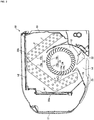
- Fig. 2 is a view for describing a longitudinal sectional configuration of the indoor unit Ui provided at the air-conditioner 100 according to the embodiment.
- the indoor unit Ui includes not only an indoor heat exchanger 15 and an indoor fan 16, but also a drain pan 18, a housing base 19, filters 20a, 20b, a front panel 21, a right-left wind deflector 22, an upper-lower wind deflector 23, and a fan cleaning unit 24. Note that in Fig. 2 , a state in which cleaning of the indoor fan 16 by the fan cleaning unit 24 is not performed is illustrated.
- the indoor heat exchanger 15 has multiple fins f and multiple heat transfer pipes g penetrating these fins f. From another point of view, the indoor heat exchanger 15 has a front indoor heat exchanger 15a and a back indoor heat exchanger 15b. The front indoor heat exchanger 15a is arranged on a front side of the indoor fan 16. On the other hand, the back indoor heat exchanger 15b is arranged on a back side of the indoor fan 16. Moreover, an upper end portion of the front indoor heat exchanger 15a and an upper end portion of the back indoor heat exchanger 15b are connected to each other.
- the drain pan 18 is configured to receive condensation water from the indoor heat exchanger 15, and is arranged below the indoor heat exchanger 15 (in an example illustrated in Fig. 2 , the front indoor heat exchanger 15a).
- the indoor fan 16 is, for example, a cylindrical cross-flow fan, and is arranged in the vicinity of the indoor heat exchanger 15.
- the indoor fan 16 includes multiple fan blades 16a, a partition plate 16b on which these fan blades 16a are placed, and an indoor fan motor 16m (see Fig. 8 ) as a drive source.
- the indoor fan 16 is preferably coated with a hydrophilic coating agent.
- a hydrophilic coating agent for example, an agent obtained in such a manner that a binder (a silicon compound having a hydrolyzable group), butanol, tetrahydrofuran, and an antibacterial agent are added to isopropyl alcohol-dispersed silica sol as a hydrophilic material may be used as the coating agent.
- a hydrophilic film is formed on a surface of the indoor fan 16.
- an electric resistance value of the surface of the indoor fan 16 decreases, and adherence of dust to the indoor fan 16 less occurs. That is, during drive of the indoor fan 16, static electricity due to friction with air is less caused on the surface of the indoor fan 16, and therefore, adherence of dust to the indoor fan 16 can be reduced.
- the coating agent also functions as an antistatic agent for the indoor fan 16.
- the housing base 19 illustrated in Fig. 2 is a housing in which equipment such as the indoor heat exchanger 15 and the indoor fan 16 is placed.
- the filter 20a is configured to remove dust from air toward a front air suction port h1, and is placed on a front side of the indoor heat exchanger 15.
- the filter 20b is configured to remove dust from air toward an upper air suction port h2, and is placed above the indoor heat exchanger 15.
- the front panel 21 is a panel placed to cover the front filter 20a, and is rotatably movable forward about a lower end of the front panel 21. Note that it may be configured such that the front panel 21 is not rotatably movable.
- the right-left wind deflector 22 is a plate-shaped member configured to adjust the right-to-left flow of air blown into a room by rotation of the indoor fan 16.
- the right-left wind deflector 22 is arranged at a blow wind path h3, and is rotatably movable in the right-to-left direction by a right-left wind deflector motor 25 (see Fig. 8 ).
- the upper-lower wind deflector 23 is a plate-shaped member configured to adjust the upper-to-lower flow of air blown into the room by rotation of the indoor fan 16.
- the upper-lower wind deflector 23 is arranged in the vicinity of an air blow port h4, and is rotatably movable in an upper-to-lower direction by an upper-lower wind deflector motor 26 (see Fig. 8 ).
- the air flowing in the blow wind path h3 is guided in a predetermined direction by the right-left wind deflector 22 and the upper-lower wind deflector 23, and is further blown into the room through the air blow port h4.
- the indoor heat exchanger 15 and the indoor fan 16 are preferably cleaned on a regular basis. For this reason, in the present embodiment, after the indoor fan 16 has been cleaned using the subsequently-described fan cleaning unit 24, the indoor heat exchanger 15 is washed with water.
- the fan cleaning unit 24 illustrated in Fig. 2 is configured to clean the indoor fan 16, and is arranged between the indoor heat exchanger 15 and the indoor fan 16. More specifically, the fan cleaning unit 24 is arranged in a recessed portion r of the front indoor heat exchanger 15a in a doglegged shape as viewed in a longitudinal section. In the example illustrated in Fig. 2 , the indoor heat exchanger 15 (a lower portion of the front indoor heat exchanger 15a) and the drain pan 18 are present below the fan cleaning unit 24.
- the fan cleaning unit 24 is, for example, partially made of nylon.
- a fan cleaning device of Patent Document 1 described above includes an operation mode change section configured to operate the cleaning device with a previous mode being changed for a certain period of time. Every time predetermined operation time is accumulated by an operation time accumulation section, the previous mode can be changed for the certain period of time, and cleaning operation can be automatically performed with no user instruction.
- the operation mode before a change by the operation mode change section is an air-heating operation mode, heat is applied to a brush 24b right after air-heating operation. If fan cleaning is performed as it is, there is a problem that the brush 24b deforms.
- the above-described air blower fan is driven with a first rotation speed until a lapse of the first predetermined time after stop of the air-heating operation.
- the rotation speed changes to a second rotation speed faster than the first rotation speed.
- the indoor fan 16 in a case where the indoor fan 16 is cleaned by the fan cleaning unit 24 after the end of an air-cooling or dehumidification operation mode, the indoor fan 16 is driven with the first rotation speed for second predetermined time (the second predetermined time ⁇ the first predetermined time), and when cleaning of the indoor fan 16 by the fan cleaning unit 24 begins after a lapse of the second predetermined time, the rotation speed of the indoor fan 16 changes to the second rotation speed higher than the first rotation speed.
- the inside of the room can be dried and fan cleaning can be performed within a short period of time right after the end of the air-cooling or dehumidification operation mode.
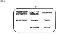
- Fig. 3 is a view for describing the lamp display unit of the indoor unit Ui according to the embodiment.
- the operation state is indicated by lighting of the lamps of the lamp display unit 50.
- the lamps include, for example, an "OPERATION” lamp to be turned on during operation, a “TIMER” lamp to be turned on during, e.g., timer reservation, a "CLEAN” lamp to be turned on during, e.g., filter cleaning (a filter cleaning mode), an indoor fan cleaning (a fan cleaning mode), and heat exchanger washing (a cleaning mode), an "eco” lamp to be turned on during eco operation, an "IN-ROOM” lamp to be turned on when a person is detected, an "AUTO-OFF” lamp to be turned on during, e.g., auto-off setting or auto-save in the eco operation, a "PREHEATING/DEFROSTING” lamp to be turned on during preheating/defrosting operation, and a "MONITORING” lamp to be turned on during monitoring of occurrence of
- the lamp displayed for the fan cleaning mode will be described with reference to Fig. 4 as compared to the lamp displayed for the filter cleaning mode.
- Fig. 4A is a view for describing the filter cleaning mode when the clean lamp is ON.
- Fig. 4B is a view for describing the fan cleaning mode (within the first predetermined time) when the clean lamp is ON.
- Fig. 4C is a view for describing the fan cleaning mode (after a lapse of the first predetermined time) when the clean lamp is ON. Note that the left side of Figs. 4A, 4B, and 4C illustrates an indication of the lamp display unit 50, and the right side illustrates the operation state of each mode with the side sectional configuration of the indoor unit Ui illustrated in Fig. 2 .
- the "CLEAN" lamp of the lamp display unit 50 is ON, and the upper-lower wind deflector 23 of the indoor unit Ui is at a position during stop of the operation.
- the user recognizes that the air-conditioning operation is stopped and internal cleaning (specifically, the filters 20a, 20b) of the indoor unit Ui is being performed.
- the "OPERATION" lamp of the lamp display unit 50 is ON, and the "CLEAN” lamp is ON.
- the direction of the upper-lower wind deflector 23 of the indoor unit Ui is, as illustrated in Fig. 4B , set to the horizontal direction or an upward direction in an indoor space. Air is basically blown, and therefore, the horizontal direction or the upward direction in the indoor space is set such that no air contacts the person in the room. Thus, the user recognizes that cleaning of the indoor fan 16 of the indoor unit Ui is being performed during air blowing operation.
- the direction of the upper-lower wind deflector 23 may be 10 degrees downward from the horizontal direction. In this case, contact of air with the person in the room can be also prevented. Thus, a downward direction of about 10 degrees from the horizontal direction is also included in the upward direction in the indoor space.
- the "OPERATION" lamp of the lamp display unit 50 is ON, and the "CLEAN” lamp is ON. In terms of lighting of the lamps, this case is the same as that of Fig. 4B , and therefore, is not distinguishable.
- the direction of the upper-lower wind deflector 23 of the indoor unit Ui is set to the position during stop of the operation.
- the front panel 21 is also closed. Thus, the user recognizes that fan cleaning is being performed. Note that in Fig. 4C , the upper-lower wind deflector 23 is closed, but fan cleaning may be performed at a wind direction position of Fig. 4B .
- the front panel 21 is closed in Fig. 4C , but fan cleaning may be performed in an open state as in Fig. 4B .
- a control unit 30 (see Fig. 8 ) of the air-conditioner 100 drives the indoor fan 16 with the upper-lower wind deflector 23 being set to the upward direction in the indoor space or the horizontal direction until a lapse of the first predetermined time after stop of the air-heating operation.
- the control unit 30 may maintain a state in which the upper-lower wind deflector 23 is in the upward direction in the indoor space or the horizontal direction, or may close the upper-lower wind deflector 23.
- heat is released within the first predetermined time after the end of the air-heating operation mode, and therefore, deformation of the brush 24b can be prevented.
- contact of air with the person in the room can be prevented.
- the air-conditioner 100 may include one or more display lamps for displaying the operation state, and the control unit 30 may turn on the same display lamp as that turned on during cleaning of the indoor fan 16 by the fan cleaning unit 24 until a lapse of the above-described first predetermined time after stop of the air-heating operation. With this configuration, it is recognized that cleaning is performed upon air blowing.
- the indoor unit Ui having the filter cleaning mode includes a filter cleaning unit (a filter cleaning section).
- the indoor heat exchanger 15 ( Fig. 2 ) in the indoor unit Ui ( Fig. 2 ) includes the filters 20a, 20b ( Fig. 2 ) above or in the front of the indoor heat exchanger 15, and large dust is removed such that contamination of the indoor heat exchanger 102 and the indoor fan 16 is prevented.
- dust is accumulated on the filters 20a, 20b, clogging occurs, air passing through the indoor heat exchanger 15 decreases, and the air-cooling/heating capacity of the indoor unit Ui decreases.
- the filter cleaning unit of the indoor unit Ui automatically cleans the filters 20a, 20b by means of the brush (not shown) after the end of the operation such as air-cooling/heating.
- the indoor fan 16 is preferably cleaned on a regular basis.
- the filter cleaning unit is preferably executed.
- filter cleaning can be also performed within the first predetermined time as preprocessing of fan cleaning, and therefore, clean processing for the air-conditioner 100 can be properly performed.
- the upper-lower wind deflector 23 is not necessarily fully closed, but preferably turns up.
- filter cleaning by the filter cleaning unit may be executed until a lapse of the first predetermined time after stop of the air-heating operation.
- the indoor fan 16 may be driven for at least part of a period during execution of filter cleaning by the filter cleaning unit to release hot air from the indoor unit Ui.
- the filter cleaning time may be, in some cases, about 20 minutes and the first predetermined time as a preprocessing period of fan cleaning may be about five minutes, for example.
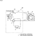
- Fig. 5 is a diagram for describing a refrigerant circuit Q of the air-conditioner 100 according to the embodiment.
- Solid arrows of Fig. 5 indicate the flow of refrigerant in the air-heating operation.
- Dashed arrows of Fig. 5 indicate the flow of refrigerant in the air-cooling operation.
- the air-conditioner 100 includes a compressor 11, an outdoor heat exchanger 12, an outdoor fan 13, and an expansion valve 14.
- the air-conditioner 100 includes the indoor heat exchanger (the heat exchanger) 15, the indoor fan (the air blower fan) 16, and a four-way valve 17.
- the compressor 11 is equipment configured to compress low-temperature low-pressure gas refrigerant by drive of a compressor motor 11a to discharge high-temperature high-pressure gas refrigerant.
- the outdoor heat exchanger 12 is a heat exchanger configured to exchange heat between refrigerant flowing in a heat transfer pipe (not shown) of such a heat exchanger and external air sent from the outdoor fan 13.
- the outdoor fan 13 is a fan configured to send external air to the outdoor heat exchanger 12 by drive of an outdoor fan motor 13a, and is placed in the vicinity of the outdoor heat exchanger 12.
- the expansion valve 14 is a valve configured to depressurize refrigerant condensed in a "condenser” (the outdoor heat exchanger 12 in the case of the air-cooling operation, and the indoor heat exchanger 15 in the case of the air-heating operation). Note that the refrigerant depressurized in the expansion valve 14 is guided to an "evaporator" (the indoor heat exchanger 15 in the case of the air-cooling operation, and the outdoor heat exchanger 12 in the case of the air-heating operation).
- the indoor heat exchanger 15 is a heat exchanger configured to exchange heat between refrigerant flowing in the heat transfer pipes g (see Fig. 2 ) of such a heat exchanger and indoor air (air in an air-conditioning target space) sent from the indoor fan 16.
- the indoor fan 16 is a fan configured to send indoor air to the indoor heat exchanger 15 by drive of the indoor fan motor 16m (a drive device, and see Fig. 8 ), and is placed in the vicinity of the indoor heat exchanger 15.
- the four-way valve 17 is a valve configured to switch a refrigerant flow path according to the operation mode of the air-conditioner 100. For example, in the air-cooling operation (see the dashed arrows of Fig. 1 ), refrigerant circulates in the refrigeration cycle in the refrigerant circuit Q configured such that the compressor 11, the outdoor heat exchanger 12 (the condenser), the expansion valve 14, and the indoor heat exchanger 15 (the evaporator) are sequentially connected in an annular shape through the four-way valve 17.
- refrigerant circulates in the refrigeration cycle in the refrigerant circuit Q configured such that the compressor 11, the indoor heat exchanger 15 (the condenser), the expansion valve 14, and the outdoor heat exchanger 12 (the evaporator) are sequentially connected in an annular shape through the four-way valve 17.
- the compressor 11, the outdoor heat exchanger 12, the outdoor fan 13, the expansion valve 14, and the four-way valve 17 are placed at the outdoor unit Uo.
- the indoor heat exchanger 15 and the indoor fan 16 are placed at the indoor unit Ui.
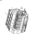
- Fig. 6 is a partially-cutout perspective view of the indoor unit Ui provided at the air-conditioner 100 according to the embodiment.
- the fan cleaning unit 24 includes a fan cleaning motor 24m (see Fig. 8 ).
- the shaft portion 24a is a rod-shaped member parallel to an axial direction of the indoor fan 16, and both ends of the shaft portion 24a are pivotally supported.
- the brush 24b is for removing dust adhering to the fan blades 16a, and is placed at the shaft portion 24a.
- the fan cleaning motor 24m (see Fig. 8 ) is, for example, a stepping motor, and has the function of rotating (rotatably moving) the shaft portion 24a by a predetermined angle.
- the fan cleaning motor 24m (see Fig. 8 ) is driven, and the indoor fan 16 is rotated backward. Accordingly, the brush 24b contacts the indoor fan 16 (see Fig. 10 ). Then, when cleaning of the indoor fan 16 by the fan cleaning unit 24 ends, the fan cleaning motor 24m is driven again to rotatably move the brush 24b, leading to a state in which the brush 24b is separated from the indoor fan 16 (see Fig. 2 ).
- a tip end of the brush 24b faces the indoor heat exchanger 15 in other states than cleaning of the indoor fan 16, as illustrated in Fig. 2 .
- the brush 24b is separated from the indoor fan 16 with the brush 24b being in a lateral direction (the substantially horizontal direction).
- Fig. 7 is a view for describing the flow of air in the vicinity of the fan cleaning unit 24 during the air-conditioning operation in the air-conditioner 100 according to the embodiment.
- the direction of each arrow illustrated in Fig. 7 indicates a direction in which air flows.
- the length of each arrow indicates a speed at which air flows.
- the indoor fan 16 rotates forward, and air passing through a clearance between adjacent ones of the fins f of the front indoor heat exchanger 15a flows toward the indoor fan 16.
- air flows toward the indoor fan 16 in the lateral direction (the substantially horizontal direction) as illustrated in Fig. 7 .
- the brush 24b of the fan cleaning unit 24 is positioned in the substantially horizontal direction, but is not limited to above. In a case where the brush 24b is long, the direction of the brush may be fixed horizontally diagonally in a downward direction, i.e., fixed at a position slightly contacting the front indoor heat exchanger 15a.
- the fan cleaning unit 24 is arranged with the brush 24b facing the lateral direction, as described above.
- the direction of the brush 24b is parallel to an air flow direction.
- an extension direction of the brush 24b and the air flow direction are substantially parallel to each other, and therefore, the fan cleaning unit 24 rarely interferes with the air flow.
- the fan cleaning unit 24 is not arranged in a midstream/downstream region (the vicinity of the air blow port h4 illustrated in Fig. 2 ) of the air flow in a case where the indoor fan 16 rotates forward, but is arranged in an upstream region. Air flowing in the lateral direction along the brush 24b is accelerated by the fan blades 16a, and the accelerated air flows toward the air blow port h4 (see Fig. 2 ). As described above, the fan cleaning unit 24 is arranged in the upstream region where air flows at a relatively-low speed, and therefore, a decrease in a wind volume due to the fan cleaning unit 24 can be suppressed. Note that even when the indoor fan 16 is stopped, the fan cleaning unit 24 may be maintained in a state similar to that of Fig. 7 .
- Fig. 8 is a block diagram of control functions of the air-conditioner 100 according to the embodiment.
- the indoor unit Ui illustrated in Fig. 8 includes the remote controller transmission/reception unit 27 as described above and an indoor control circuit 31.
- the remote controller transmission/reception unit 27 exchanges predetermined information with the remote controller 40.
- the indoor control circuit 31 includes electronic circuits such as a central processing unit (CPU), a read only memory (ROM), a random access memory (RAM), and various interfaces.
- CPU central processing unit
- ROM read only memory
- RAM random access memory
- a program stored in the ROM is read and deployed in the RAM, and the CPU executes various types of processing.
- the indoor control circuit 31 includes a storage unit 31a and an indoor control unit 31b.
- the storage unit 31a stores, for example, data received via the remote controller transmission/reception unit 27 and detection values of various sensors (not shown).
- the indoor control unit 31b runs the fan cleaning motor 24m, the indoor fan motor 16m, the right-left wind deflector motor 25, and the upper-lower wind deflector motor 26. In addition to the function of running the motor and the like, the indoor control unit 31b has the function of causing the fan cleaning unit 24 to contact the indoor fan 16.
- the storage unit 31a stores the number of times of operation of the air-conditioner 100 and the cumulative operation time of the air-conditioner 100.
- the indoor control unit 31b executes the fan cleaning mode based on the number of times of operation and/or the cumulative operation time.
- the outdoor unit Uo includes an outdoor control circuit 32.
- the outdoor control circuit 32 includes electronic circuits such as a CPU, a ROM, a RAM, and various interfaces, and is connected to the indoor control circuit 31 via a communication line.
- the outdoor control circuit 32 includes a storage unit 32a and an outdoor control unit 32b.
- the storage unit 32a stores, for example, data received from the indoor control circuit 31.
- the outdoor control unit 32b controls, for example, the compressor motor 11a, the outdoor fan motor 13a, and the expansion valve 14.
- the indoor control circuit 31 and the outdoor control circuit 32 will be collectively referred to as the "control unit 30.”
- Fig. 9 is a flowchart of control processing executed by the control unit 30 of the air-conditioner 100 according to the embodiment (see Fig. 2 , as necessary). In this processing, it is assumed that at a step S101, the air-heating operation is stopped and the tip end of the brush 24b faces the front indoor heat exchanger 15a (a state illustrated in Fig. 2 ).
- the control unit 30 performs, for the indoor fan 16, the air blowing operation for the first predetermined time.
- hot air can be released from the indoor unit Ui to the outside, and the heated brush 24b can be cooled.
- the indoor fan 16 is cleaned by the fan cleaning unit 24 after a lapse of the first predetermined time. A state during cleaning of the indoor fan 16 will be described with reference to Fig. 10 .
- Fig. 10 is a view for describing the state during cleaning of the indoor fan 16 in the air-conditioner 100 according to the embodiment. Note that in Fig. 10 , the indoor heat exchanger 15, the indoor fan 16, and the drain pan 18 are illustrated, but other members are not shown.
- the control unit 30 rotates (rotates backward) the indoor fan 16 in a direction opposite to that of the normal air-conditioning operation, and when the indoor fan 16 reaches a set rotation speed Rc, causes the brush 24b of the fan cleaning unit 24 to contact the indoor fan 16.
- control unit 30 rotatably moves the brush 24b about 180° about the shaft portion 24a from a state (see Fig. 2 ) in which the tip end of the brush 24b faces the indoor heat exchanger 15, and causes the tip end of the brush 24b to face the indoor fan 16 (see Fig. 10 ). Accordingly, the brush 24b contacts the fan blade 16a of the indoor fan 16.
- the indoor fan 16 rotates backward.
- the tip end of the brush 24b deflects due to movement of the fan blade 16a, and the brush 24b is pressed to rub a back surface of the fan blade 16a. Then, dust accumulated in the vicinity of a tip end (an end portion in a radial direction) of the fan blade 16a is removed by the brush 24b.
- dust tends to be accumulated in the vicinity of the tip end of the fan blade 16a. This is because during the air-conditioning operation (see Fig. 4 ) in which the indoor fan 16 is rotating forward, air contacts the vicinity of a tip end of the front of the fan blade 16a, and dust adheres to the vicinity of such a tip end.
- the air having contact the vicinity of the tip end of the fan blade 16a passes through a clearance between adjacent ones of the fan blades 16a along a curved surface of the front of the fan blade 16a.
- the indoor fan 16 is rotated backward, and when the indoor fan 16 reaches the set rotation speed Rc, the fan cleaning unit 24 contacts the fan blade 16a. Accordingly, the brush 24b contacts the vicinity of a tip end of the back surface of the fan blade 16a, and dust accumulated in the vicinity of the tip end of the back surface of the fan blade 16a is removed. As a result, most of dust accumulated on the indoor fan 16 can be removed.
- the indoor fan 16 is rotated backward, and accordingly, a gentle air flow in a direction opposite to that upon forward rotation (see Fig. 4 ) is generated inside the indoor unit Ui (see Fig. 2 ).
- dust j removed from the indoor fan 16 does not flow toward the air blow port h4 (see Fig. 2 ), but as illustrated in Fig. 10 , is guided to the drain pan 18 through a clearance between the front indoor heat exchanger 15a and the indoor fan 16.
- the dust j removed from the indoor fan 16 by the brush 24b is slightly pressed against the front indoor heat exchanger 15a with a wind pressure. Further, the above-described dust j drops onto the drain pan 18 along an inclined surface (an edge of the fin f) of the front indoor heat exchanger 15a (see an arrow of Fig. 10 ). Thus, the dust j rarely adheres to a back surface of the upper-lower wind deflector 23 (see Fig. 2 ) through a slight clearance between the indoor fan 16 and the drain pan 18. Thus, blowing of the dust j into the room during next air-conditioning operation can be prevented.
- control unit 30 may drive the indoor fan 16 at a medium/high rotation speed, or drive the indoor fan 16 at a low rotation speed.
- the range of the medium/high rotation speed of the indoor fan 16 is, for example, equal to or higher than 300 min -1 (300 rpm) and lower than 1700 min -1 (1700 rpm).
- the indoor fan 16 is rotated at the medium/high speed as described above, and therefore, the dust j tends to flow toward the front indoor heat exchanger 15a.
- the dust j less adheres to the back surface of the upper-lower wind deflector 23 (see Fig. 2 ).
- blowing of the dust j into the room during the next air-conditioning operation can be prevented.
- the range of the low rotation speed of the indoor fan 16 is, for example, equal to or higher than 100 min -1 (100 rpm) and lower than 300 min -1 (300 rpm).
- the indoor fan 16 is rotated at the low speed as described above, and therefore, cleaning of the indoor fan 16 can be performed with low noise.
- the control unit 30 moves the fan cleaning unit 24 at a step S104. That is, the control unit 30 rotatably moves the brush 24b about 180° about the shaft portion 24a from a state (see Fig. 10 ) in which the tip end of the brush 24b faces the indoor fan 16, and causes the tip end of the brush 24b to face the indoor heat exchanger 15 (see Fig. 11 ). This can prevent the fan cleaning unit 24 from interfering with the air flow during subsequent air-conditioning operation.
- control unit 30 sequentially performs freezing/unfreezing of the indoor heat exchanger 15 at a step S105.
- the control unit 30 causes the indoor heat exchanger 15 to function as the evaporator, thereby forming frost of moisture contained in air taken into the indoor unit Ui on the indoor heat exchanger 15 and freezing the indoor heat exchanger 15. Note that the processing of freezing the indoor heat exchanger 15 is included in the matter of "causing condensation water to adhere to" the indoor heat exchanger 15.
- the control unit 30 When the indoor heat exchanger 15 is frozen, the control unit 30 preferably decreases the evaporation temperature of refrigerant flowing into the indoor heat exchanger 15. That is, the control unit 30 causes the indoor heat exchanger 15 to function as the evaporator, thereby adjusting the temperature of refrigerant flowing into the indoor heat exchanger 15 such that the refrigerant evaporation temperature becomes lower than that of the normal air-conditioning operation when the indoor heat exchanger 15 is frozen (the condensation water adheres to the indoor heat exchanger 15).
- control unit 30 decreases the degree of opening of the expansion valve 14 (see Fig. 1 ), thereby causing low-pressure refrigerant with a low evaporation temperature to flow into the indoor heat exchanger 15. Accordingly, frost or ice (a reference character i illustrated in Fig. 11 ) is easily grown on the indoor heat exchanger 15, and therefore, the indoor heat exchanger 15 can be washed with a great amount of water during subsequent unfreezing.
- a region of the indoor heat exchanger 15 positioned below the fan cleaning unit 24 is not the downstream region of the flow of refrigerant flowing in the indoor heat exchanger 15 (i.e., is the upstream region or the midstream region).
- low-temperature gas-liquid two-phase refrigerant flows at least below (a lower side) the fan cleaning unit 24, and therefore, the thickness of frost or ice adhering to the indoor heat exchanger 15 can be great.
- the indoor heat exchanger 15 can be washed with a great amount of water.
- the control unit 30 When the indoor heat exchanger 15 functions as the evaporator and is frozen (the condensation water adheres to the indoor heat exchanger 15), the control unit 30 preferably closes the upper-lower wind deflector 23 (see Fig. 2 ) or sets the angle of the upper-lower wind deflector 23 to an upward angle with respect to the horizontal direction. With this configuration, leakage of low-temperature air cooled in the indoor heat exchanger 15 into the room can be reduced, and, e.g., freezing of the indoor heat exchanger 15 can be performed in a state comfortable for the user.
- the control unit 30 unfreezes the indoor heat exchanger 15 (the step S105 of Fig. 9 ). For example, the control unit 30 maintains a stop state of each type of equipment to naturally unfreeze the indoor heat exchanger 15 at room temperature. Note that the control unit 30 may perform the air blowing operation to melt frost or ice adhering to the indoor heat exchanger 15. A state during unfreezing of the indoor heat exchanger 15 will be described with reference to Fig. 11 .
- Fig. 11 is a view for describing the state during unfreezing of the indoor heat exchanger 15 in the air-conditioner 100 according to the embodiment.
- the indoor heat exchanger 15 is unfrozen, and accordingly, frost or ice adhering to the indoor heat exchanger 15 is melted and a great amount of water w flows down to the drain pan 18 along the fin f.
- the dust j having adhered to the indoor heat exchanger 15 during the air-conditioning operation can be washed away.
- the dust j adhering to the front indoor heat exchanger 15a is also washed away, and drops onto the drain pan 18 (see an arrow of Fig. 11 ).
- the water w having flowed down to the drain pan 18 as described above is, together with the dust j (see Fig. 10 ) having directly dropped onto the drain pan 18 during cleaning of the indoor fan 16, discharged to the outside through a drain hose (not shown).
- a drain hose not shown
- control unit 30 may perform the air blowing operation to dry the inside of the indoor unit Ui after freezing/unfreezing (the step S105) of the indoor heat exchanger 15 has been performed. With this configuration, growth of bacteria in the indoor heat exchanger 15 and the like can be reduced.
- the air-conditioner 100 according to the present invention has been described above with reference to the embodiment, but the present invention is not limited to such description. Various changes can be made to the present invention.
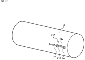
- Fig. 12 is a schematic perspective view of an indoor fan 16 and a fan cleaning unit 24A provided at an air-conditioner according to another variation.
- the fan cleaning unit 24A includes a rod-shaped shaft portion 24d parallel to an axial direction of the indoor fan 16, a brush 24e placed at the shaft portion 24d, and a pair of support portions 24f placed at both ends of the shaft portion 24d.
- the fan cleaning unit 24A also includes a movement mechanism configured to move the fan cleaning unit 24A in, e.g., the axial direction.
- the length of the fan cleaning unit 24A in a direction parallel to the axial direction of the indoor fan 16 is shorter than the length of the indoor fan 16 itself in the axial direction.
- the fan cleaning unit 24A moves in the axial direction of the indoor fan 16 (a right-to-left direction as viewed from the front of an indoor unit Ui). That is, in the axial direction of the indoor fan 16, the indoor fan 16 is sequentially cleaned in every predetermined region corresponding to the length of the fan cleaning unit 24A. It is configured such that the fan cleaning unit 24A with a relatively-short length moves as described above, and therefore, an air-conditioner manufacturing cost can be reduced as compared to the configuration illustrated in Fig. 6 .
- a rod (not shown) extending parallel to the shaft portion 24d may be provided in the vicinity (e.g., on an upper side of the shaft portion 24d) of the fan cleaning unit 24A, and the predetermined movement mechanism (not shown) may move the fan cleaning unit 24A along such a rod.
- the movement mechanism may rotatably move the fan cleaning unit 24A or move the fan cleaning unit 24A in parallel as necessary to retreat the fan cleaning unit 24A from the indoor fan 16.
- control unit 30 may cause the fan cleaning unit 24 to contact the indoor fan 16, and may rotate (rotate forward) the indoor fan 16 in the same direction as that in the normal air-conditioning operation.
- a rotation speed when the indoor fan 16 is rotated forward during cleaning may be, as in the embodiment, any of low/medium/high speeds.
- the present invention is not limited to above.
- the control unit 30 may move the shaft portion 24a toward the indoor fan 16, and may cause the brush 24b to contact the indoor fan 16. Then, after the end of cleaning of the indoor fan 16, the control unit 30 may retreat the shaft portion 24a to separate the brush 24b from the indoor fan 16.
- the present invention is not limited to above. That is, as long as a member which can clean the indoor fan 16 is employed, a sponge or the like may be used.
- control unit 30 causes the brush 24b of the fan cleaning unit 24 to contact the indoor fan 16 during cleaning of the indoor fan 16
- the present invention is not limited to above. That is, during cleaning of the indoor fan 16, the control unit 30 may cause the brush 24b of the fan cleaning unit 24 to approach the indoor fan 16. More specifically, the control unit 30 causes the brush 24b to approach the indoor fan 16 to such an extent that dust accumulated on a tip end of the fan blade 16a and grown to the outside in a radial direction with respect to such a tip end can be removed. With this configuration, dust accumulated on the indoor fan 16 can be also properly removed.
- each embodiment has been described in detail for the sake of clear description of the present invention, and is not limited to one including all configurations described above. Further, for some of the configurations of each embodiment, addition/omission/replacement of other configurations may be made. In addition, the above-described mechanisms and configurations are those considered necessary for description, and not all mechanisms and configurations necessary for a product have not been described.
Landscapes
- Engineering & Computer Science (AREA)
- Chemical & Material Sciences (AREA)
- Combustion & Propulsion (AREA)
- Mechanical Engineering (AREA)
- General Engineering & Computer Science (AREA)
- Signal Processing (AREA)
- Physics & Mathematics (AREA)
- Fuzzy Systems (AREA)
- Mathematical Physics (AREA)
- Human Computer Interaction (AREA)
- Air Conditioning Control Device (AREA)
- Air-Conditioning Room Units, And Self-Contained Units In General (AREA)
Abstract
Description
- The present invention to an air-conditioner.
- For example,
Patent Document 1 describes, as the technique of cleaning an indoor fan (a fan) of an air-conditioner, one including a fan cleaning device for removing dust on the fan. Moreover,Fig. 1 ofPatent Document 1 illustrates a configuration in which the fan cleaning device is placed in the vicinity of a blow port of the indoor fan. - Patent Document 1: Japanese Patent No.
4046755 - In the technique described in
Patent Document 1, the fan cleaning device has a brush-shaped member configured to contact the fan to remove dust on the fan. Moreover, the fan cleaning device includes an operation mode change section configured to operate the cleaning device with a previous mode being changed for a certain period of time. Every time predetermined operation time is accumulated by an operation time accumulation section, the previous mode can be changed for the certain period of time, and cleaning operation can be automatically performed with no user instruction. However, in the case of the operation mode change section, a state before the operation mode is changed is not taken into consideration, and for this reason, problems such as acceleration of deformation of the brush are caused depending on the status of the operation mode. - For this reason, an object of the present invention is to provide an air-conditioner configured so that deformation of a fan cleaning member can be prevented.
- For solving the above-described problems, the air-conditioner according to the present invention includes an indoor heat exchanger, an air blower fan (e.g., an indoor fan 16) configured to send air to the indoor heat exchanger, a fan cleaning unit configured to clean the air blower fan, and a control unit configured to control the fan cleaning unit. In a case where the air blower fan is cleaned by the fan cleaning unit after the end of air-heating operation, the control unit executes, after the end of the air-heating operation, cleaning of the air blower fan by the fan cleaning unit after a lapse of first predetermined time after stop of the air-heating operation.
- According to the present invention, deformation of the fan cleaning member can be prevented.
-
-
Fig. 1 is a view of an external configuration of an air-conditioner according to an embodiment; -
Fig. 2 is a view for describing a side sectional configuration of an indoor unit of the air-conditioner according to the embodiment; -
Fig. 3 is a view for describing a lamp display unit of the indoor unit according to the embodiment; -
Fig. 4A is a view for describing a filter cleaning mode when a clean lamp is ON; -
Fig. 4B is a view for describing a fan cleaning mode (within first predetermined time) when the clean lamp is ON; -
Fig. 4C is a view for describing the fan cleaning mode (after the first predetermined time) when the clean lamp is ON; -
Fig. 5 is a diagram for describing a refrigerant circuit of the air-conditioner according to the embodiment; -
Fig. 6 is a partially-cutout perspective view of the indoor unit provided at the air-conditioner according to the embodiment; -
Fig. 7 is a view for describing the flow of air in the vicinity of a fan cleaning unit during air-conditioning operation in the air-conditioner according to the embodiment; -
Fig. 8 is a block diagram of control functions of the air-conditioner according to the embodiment; -
Fig. 9 is a flowchart of control processing executed by a control unit of the air-conditioner according to the embodiment; -
Fig. 10 is a view for describing a state during cleaning of an indoor fan in the air-conditioner according to the embodiment; -
Fig. 11 is a view for describing a state during unfreezing of an indoor heat exchanger in the air-conditioner according to the embodiment; and -
Fig. 12 is a schematic perspective view of an indoor fan and a fan cleaning unit provided at an air-conditioner according to another variation of the present invention. - An embodiment for carrying out the present invention will be described in detail with reference to the drawings, as necessary.
-
Fig. 1 is a view of an external configuration of an air-conditioner according to the embodiment. The air-conditioner 100 is equipment configured to circulate refrigerant in a refrigeration cycle (a heat pump cycle) to perform air-conditioning. The air-conditioner 100 has an indoor unit Ui, an outdoor unit Uo, and a remote controller 40 (an air-conditioning control terminal) configured to communicate with the indoor unit Ui via infrared light, a radio wave, a communication line, or the like to operate the air-conditioner 100 by a user. Moreover, the indoor unit Ui and the outdoor unit Uo are connected to each other via a refrigerant pipe and a communication cable. Animage capturing unit 28 is arranged at the center of the indoor unit Ui in a right-to-left direction. A remote controller transmission/reception unit 27 is arranged at a remote controller signal easily-receivable position in the vicinity of a lower front portion of the indoor unit Ui. Moreover, a lamp display unit 50 (seeFig. 3 ) indicating various operation states by lighting of lamps is provided next to theimage capturing unit 28. -
Fig. 2 is a view for describing a longitudinal sectional configuration of the indoor unit Ui provided at the air-conditioner 100 according to the embodiment. The indoor unit Ui includes not only anindoor heat exchanger 15 and anindoor fan 16, but also adrain pan 18, ahousing base 19,filters front panel 21, a right-left wind deflector 22, an upper-lower wind deflector 23, and afan cleaning unit 24. Note that inFig. 2 , a state in which cleaning of theindoor fan 16 by thefan cleaning unit 24 is not performed is illustrated. - The
indoor heat exchanger 15 has multiple fins f and multiple heat transfer pipes g penetrating these fins f. From another point of view, theindoor heat exchanger 15 has a frontindoor heat exchanger 15a and a backindoor heat exchanger 15b. The frontindoor heat exchanger 15a is arranged on a front side of theindoor fan 16. On the other hand, the backindoor heat exchanger 15b is arranged on a back side of theindoor fan 16. Moreover, an upper end portion of the frontindoor heat exchanger 15a and an upper end portion of the backindoor heat exchanger 15b are connected to each other. - The
drain pan 18 is configured to receive condensation water from theindoor heat exchanger 15, and is arranged below the indoor heat exchanger 15 (in an example illustrated inFig. 2 , the frontindoor heat exchanger 15a). - The
indoor fan 16 is, for example, a cylindrical cross-flow fan, and is arranged in the vicinity of theindoor heat exchanger 15. Theindoor fan 16 includesmultiple fan blades 16a, apartition plate 16b on which thesefan blades 16a are placed, and anindoor fan motor 16m (seeFig. 8 ) as a drive source. - Note that the
indoor fan 16 is preferably coated with a hydrophilic coating agent. For example, an agent obtained in such a manner that a binder (a silicon compound having a hydrolyzable group), butanol, tetrahydrofuran, and an antibacterial agent are added to isopropyl alcohol-dispersed silica sol as a hydrophilic material may be used as the coating agent. - With this configuration, a hydrophilic film is formed on a surface of the
indoor fan 16. Thus, an electric resistance value of the surface of theindoor fan 16 decreases, and adherence of dust to theindoor fan 16 less occurs. That is, during drive of theindoor fan 16, static electricity due to friction with air is less caused on the surface of theindoor fan 16, and therefore, adherence of dust to theindoor fan 16 can be reduced. As described above, the coating agent also functions as an antistatic agent for theindoor fan 16. - The
housing base 19 illustrated inFig. 2 is a housing in which equipment such as theindoor heat exchanger 15 and theindoor fan 16 is placed. Thefilter 20a is configured to remove dust from air toward a front air suction port h1, and is placed on a front side of theindoor heat exchanger 15. Thefilter 20b is configured to remove dust from air toward an upper air suction port h2, and is placed above theindoor heat exchanger 15. - The
front panel 21 is a panel placed to cover thefront filter 20a, and is rotatably movable forward about a lower end of thefront panel 21. Note that it may be configured such that thefront panel 21 is not rotatably movable. - The right-left
wind deflector 22 is a plate-shaped member configured to adjust the right-to-left flow of air blown into a room by rotation of theindoor fan 16. The right-leftwind deflector 22 is arranged at a blow wind path h3, and is rotatably movable in the right-to-left direction by a right-left wind deflector motor 25 (seeFig. 8 ). The upper-lower wind deflector 23 is a plate-shaped member configured to adjust the upper-to-lower flow of air blown into the room by rotation of theindoor fan 16. The upper-lower wind deflector 23 is arranged in the vicinity of an air blow port h4, and is rotatably movable in an upper-to-lower direction by an upper-lower wind deflector motor 26 (seeFig. 8 ). - Air sucked through the air suction ports h1, h2 exchanges heat with refrigerant flowing in the heat transfer pipes g of the
indoor heat exchanger 15, and the air subjected to heat exchange is guided to the blow wind path h3. The air flowing in the blow wind path h3 is guided in a predetermined direction by the right-leftwind deflector 22 and the upper-lower wind deflector 23, and is further blown into the room through the air blow port h4. - By such an air flow, most of dust toward the air suction ports h1, h2 is collected by the
filters filters indoor heat exchanger 15 and theindoor fan 16. Thus, theindoor heat exchanger 15 and theindoor fan 16 are preferably cleaned on a regular basis. For this reason, in the present embodiment, after theindoor fan 16 has been cleaned using the subsequently-describedfan cleaning unit 24, theindoor heat exchanger 15 is washed with water. - The
fan cleaning unit 24 illustrated inFig. 2 is configured to clean theindoor fan 16, and is arranged between theindoor heat exchanger 15 and theindoor fan 16. More specifically, thefan cleaning unit 24 is arranged in a recessed portion r of the frontindoor heat exchanger 15a in a doglegged shape as viewed in a longitudinal section. In the example illustrated inFig. 2 , the indoor heat exchanger 15 (a lower portion of the frontindoor heat exchanger 15a) and thedrain pan 18 are present below thefan cleaning unit 24. Thefan cleaning unit 24 is, for example, partially made of nylon. - Cleaning of the
indoor fan 16 of the present embodiment will be described with a typical problem. - A fan cleaning device of
Patent Document 1 described above includes an operation mode change section configured to operate the cleaning device with a previous mode being changed for a certain period of time. Every time predetermined operation time is accumulated by an operation time accumulation section, the previous mode can be changed for the certain period of time, and cleaning operation can be automatically performed with no user instruction. However, when the operation mode before a change by the operation mode change section is an air-heating operation mode, heat is applied to abrush 24b right after air-heating operation. If fan cleaning is performed as it is, there is a problem that thebrush 24b deforms. - In fan cleaning of the present embodiment, in a case where the
indoor fan 16 is cleaned by thefan cleaning unit 24 after the end of the air-heating operation mode, cleaning of theindoor fan 16 by thefan cleaning unit 24 is, after the end of the air-heating operation, executed after a lapse of first predetermined time after stop of the air-heating operation. With this configuration, the heat applied to thebrush 24b due to the air-heating operation mode is released so that deformation of thebrush 24b can be prevented. - In fan cleaning of the present embodiment, the above-described air blower fan is driven with a first rotation speed until a lapse of the first predetermined time after stop of the air-heating operation. When cleaning of the
indoor fan 16 by thefan cleaning unit 24 begins, the rotation speed changes to a second rotation speed faster than the first rotation speed. With this configuration, hot air in the indoor unit can be released and fan cleaning can be performed within a short period of time right after the end of the air-heating operation mode. - Moreover, in fan cleaning of the present embodiment, in a case where the
indoor fan 16 is cleaned by thefan cleaning unit 24 after the end of an air-cooling or dehumidification operation mode, theindoor fan 16 is driven with the first rotation speed for second predetermined time (the second predetermined time < the first predetermined time), and when cleaning of theindoor fan 16 by thefan cleaning unit 24 begins after a lapse of the second predetermined time, the rotation speed of theindoor fan 16 changes to the second rotation speed higher than the first rotation speed. With this configuration, the inside of the room can be dried and fan cleaning can be performed within a short period of time right after the end of the air-cooling or dehumidification operation mode. -
Fig. 3 is a view for describing the lamp display unit of the indoor unit Ui according to the embodiment. The operation state is indicated by lighting of the lamps of thelamp display unit 50. The lamps include, for example, an "OPERATION" lamp to be turned on during operation, a "TIMER" lamp to be turned on during, e.g., timer reservation, a "CLEAN" lamp to be turned on during, e.g., filter cleaning (a filter cleaning mode), an indoor fan cleaning (a fan cleaning mode), and heat exchanger washing (a cleaning mode), an "eco" lamp to be turned on during eco operation, an "IN-ROOM" lamp to be turned on when a person is detected, an "AUTO-OFF" lamp to be turned on during, e.g., auto-off setting or auto-save in the eco operation, a "PREHEATING/DEFROSTING" lamp to be turned on during preheating/defrosting operation, and a "MONITORING" lamp to be turned on during monitoring of occurrence of a fungus. - In the present embodiment, the lamp displayed for the fan cleaning mode will be described with reference to
Fig. 4 as compared to the lamp displayed for the filter cleaning mode. -
Fig. 4A is a view for describing the filter cleaning mode when the clean lamp is ON.Fig. 4B is a view for describing the fan cleaning mode (within the first predetermined time) when the clean lamp is ON.Fig. 4C is a view for describing the fan cleaning mode (after a lapse of the first predetermined time) when the clean lamp is ON. Note that the left side ofFigs. 4A, 4B, and 4C illustrates an indication of thelamp display unit 50, and the right side illustrates the operation state of each mode with the side sectional configuration of the indoor unit Ui illustrated inFig. 2 . -
- (1) The filter cleaning mode is a mode for automatically cleaning the filter upon stop of the operation when conditions are satisfied. The remote controller can be operated to clean the filter.
- (2) The fan cleaning mode is a mode for automatically cleaning the
indoor fan 16 after air-conditioning operation. The remote controller can be operated to clean the air blower fan. - Any of these two modes has the function of bringing a component into a "CLEAN" state, and therefore, the "CLEAN" lamp is used. However, only with lighting of the "CLEAN" lamp, it is not clear for the user which mode is activated. For this reason, functions are grouped as follows.
- In the case of the filter cleaning mode of
Fig. 4A , the "CLEAN" lamp of thelamp display unit 50 is ON, and the upper-lower wind deflector 23 of the indoor unit Ui is at a position during stop of the operation. Thus, the user recognizes that the air-conditioning operation is stopped and internal cleaning (specifically, thefilters - In the case of the fan cleaning mode of
Figs. 4B and 4C , the "OPERATION" lamp of thelamp display unit 50 is ON, and the "CLEAN" lamp is ON. In the first predetermined period as preprocessing of fan cleaning, the direction of the upper-lower wind deflector 23 of the indoor unit Ui is, as illustrated inFig. 4B , set to the horizontal direction or an upward direction in an indoor space. Air is basically blown, and therefore, the horizontal direction or the upward direction in the indoor space is set such that no air contacts the person in the room. Thus, the user recognizes that cleaning of theindoor fan 16 of the indoor unit Ui is being performed during air blowing operation. Note that the direction of the upper-lower wind deflector 23 may be 10 degrees downward from the horizontal direction. In this case, contact of air with the person in the room can be also prevented. Thus, a downward direction of about 10 degrees from the horizontal direction is also included in the upward direction in the indoor space. - In the case of the fan cleaning mode of
Fig. 4C after a lapse of the first predetermined time, the "OPERATION" lamp of thelamp display unit 50 is ON, and the "CLEAN" lamp is ON. In terms of lighting of the lamps, this case is the same as that ofFig. 4B , and therefore, is not distinguishable. However, in the case ofFig. 4C , the direction of the upper-lower wind deflector 23 of the indoor unit Ui is set to the position during stop of the operation. Moreover, thefront panel 21 is also closed. Thus, the user recognizes that fan cleaning is being performed. Note that inFig. 4C , the upper-lower wind deflector 23 is closed, but fan cleaning may be performed at a wind direction position ofFig. 4B . Moreover, thefront panel 21 is closed inFig. 4C , but fan cleaning may be performed in an open state as inFig. 4B . - That is, a control unit 30 (see
Fig. 8 ) of the air-conditioner 100 drives theindoor fan 16 with the upper-lower wind deflector 23 being set to the upward direction in the indoor space or the horizontal direction until a lapse of the first predetermined time after stop of the air-heating operation. After a lapse of the first predetermined time after stop of the air-heating operation, thecontrol unit 30 may maintain a state in which the upper-lower wind deflector 23 is in the upward direction in the indoor space or the horizontal direction, or may close the upper-lower wind deflector 23. Thus, heat is released within the first predetermined time after the end of the air-heating operation mode, and therefore, deformation of thebrush 24b can be prevented. Moreover, upon fan cleaning, contact of air with the person in the room can be prevented. - The air-
conditioner 100 may include one or more display lamps for displaying the operation state, and thecontrol unit 30 may turn on the same display lamp as that turned on during cleaning of theindoor fan 16 by thefan cleaning unit 24 until a lapse of the above-described first predetermined time after stop of the air-heating operation. With this configuration, it is recognized that cleaning is performed upon air blowing. - A relationship between the filter cleaning mode illustrated in
Fig. 4A and the fan cleaning mode will be described. - The indoor unit Ui having the filter cleaning mode includes a filter cleaning unit (a filter cleaning section). The indoor heat exchanger 15 (
Fig. 2 ) in the indoor unit Ui (Fig. 2 ) includes thefilters Fig. 2 ) above or in the front of theindoor heat exchanger 15, and large dust is removed such that contamination of the indoor heat exchanger 102 and theindoor fan 16 is prevented. When dust is accumulated on thefilters indoor heat exchanger 15 decreases, and the air-cooling/heating capacity of the indoor unit Ui decreases. For preventing such a state, the filter cleaning unit of the indoor unit Ui automatically cleans thefilters - Most of dust toward the air suction ports h1, h2 is collected by the
filters filters indoor fan 16. For this reason, theindoor fan 16 is preferably cleaned on a regular basis. - Thus, during the above-described first predetermined time, cleaning of the
filters conditioner 100 can be properly performed. At this point, the upper-lower wind deflector 23 is not necessarily fully closed, but preferably turns up. - That is, in a case where the air-
conditioner 100 includes the filter cleaning unit (the filter cleaning section) configured to clean the filter placed on an air suction side of the indoor heat exchanger, filter cleaning by the filter cleaning unit may be executed until a lapse of the first predetermined time after stop of the air-heating operation. - Alternatively, in a case where filter cleaning time is longer than the first predetermined time, the
indoor fan 16 may be driven for at least part of a period during execution of filter cleaning by the filter cleaning unit to release hot air from the indoor unit Ui. Depending on the type of air-conditioner 100, the filter cleaning time may be, in some cases, about 20 minutes and the first predetermined time as a preprocessing period of fan cleaning may be about five minutes, for example. - Hereinafter, details of the
fan cleaning unit 24 will be described with reference toFigs. 5 to 12 . -
Fig. 5 is a diagram for describing a refrigerant circuit Q of the air-conditioner 100 according to the embodiment. Solid arrows ofFig. 5 indicate the flow of refrigerant in the air-heating operation. Dashed arrows ofFig. 5 indicate the flow of refrigerant in the air-cooling operation. As illustrated inFig. 5 , the air-conditioner 100 includes acompressor 11, anoutdoor heat exchanger 12, anoutdoor fan 13, and anexpansion valve 14. Moreover, in addition to the above-described configuration, the air-conditioner 100 includes the indoor heat exchanger (the heat exchanger) 15, the indoor fan (the air blower fan) 16, and a four-way valve 17. - The
compressor 11 is equipment configured to compress low-temperature low-pressure gas refrigerant by drive of acompressor motor 11a to discharge high-temperature high-pressure gas refrigerant. Theoutdoor heat exchanger 12 is a heat exchanger configured to exchange heat between refrigerant flowing in a heat transfer pipe (not shown) of such a heat exchanger and external air sent from theoutdoor fan 13. - The
outdoor fan 13 is a fan configured to send external air to theoutdoor heat exchanger 12 by drive of anoutdoor fan motor 13a, and is placed in the vicinity of theoutdoor heat exchanger 12. Theexpansion valve 14 is a valve configured to depressurize refrigerant condensed in a "condenser" (theoutdoor heat exchanger 12 in the case of the air-cooling operation, and theindoor heat exchanger 15 in the case of the air-heating operation). Note that the refrigerant depressurized in theexpansion valve 14 is guided to an "evaporator" (theindoor heat exchanger 15 in the case of the air-cooling operation, and theoutdoor heat exchanger 12 in the case of the air-heating operation). - The
indoor heat exchanger 15 is a heat exchanger configured to exchange heat between refrigerant flowing in the heat transfer pipes g (seeFig. 2 ) of such a heat exchanger and indoor air (air in an air-conditioning target space) sent from theindoor fan 16. Theindoor fan 16 is a fan configured to send indoor air to theindoor heat exchanger 15 by drive of theindoor fan motor 16m (a drive device, and seeFig. 8 ), and is placed in the vicinity of theindoor heat exchanger 15. - The four-
way valve 17 is a valve configured to switch a refrigerant flow path according to the operation mode of the air-conditioner 100. For example, in the air-cooling operation (see the dashed arrows ofFig. 1 ), refrigerant circulates in the refrigeration cycle in the refrigerant circuit Q configured such that thecompressor 11, the outdoor heat exchanger 12 (the condenser), theexpansion valve 14, and the indoor heat exchanger 15 (the evaporator) are sequentially connected in an annular shape through the four-way valve 17. - On the other hand, in the air-heating operation (see the solid arrows of
Fig. 1 ), refrigerant circulates in the refrigeration cycle in the refrigerant circuit Q configured such that thecompressor 11, the indoor heat exchanger 15 (the condenser), theexpansion valve 14, and the outdoor heat exchanger 12 (the evaporator) are sequentially connected in an annular shape through the four-way valve 17. - Note that in an example illustrated in
Fig. 5 , thecompressor 11, theoutdoor heat exchanger 12, theoutdoor fan 13, theexpansion valve 14, and the four-way valve 17 are placed at the outdoor unit Uo. On the other hand, theindoor heat exchanger 15 and theindoor fan 16 are placed at the indoor unit Ui. -
Fig. 6 is a partially-cutout perspective view of the indoor unit Ui provided at the air-conditioner 100 according to the embodiment. In addition to ashaft portion 24a and thebrush 24b illustrated inFig. 3 , thefan cleaning unit 24 includes afan cleaning motor 24m (seeFig. 8 ). Theshaft portion 24a is a rod-shaped member parallel to an axial direction of theindoor fan 16, and both ends of theshaft portion 24a are pivotally supported. - The
brush 24b is for removing dust adhering to thefan blades 16a, and is placed at theshaft portion 24a. Thefan cleaning motor 24m (seeFig. 8 ) is, for example, a stepping motor, and has the function of rotating (rotatably moving) theshaft portion 24a by a predetermined angle. - When the
indoor fan 16 is cleaned by thefan cleaning unit 24, thefan cleaning motor 24m (seeFig. 8 ) is driven, and theindoor fan 16 is rotated backward. Accordingly, thebrush 24b contacts the indoor fan 16 (seeFig. 10 ). Then, when cleaning of theindoor fan 16 by thefan cleaning unit 24 ends, thefan cleaning motor 24m is driven again to rotatably move thebrush 24b, leading to a state in which thebrush 24b is separated from the indoor fan 16 (seeFig. 2 ). - In the present embodiment, a tip end of the
brush 24b faces theindoor heat exchanger 15 in other states than cleaning of theindoor fan 16, as illustrated inFig. 2 . Specifically, in other states (also including a state during normal air-conditioning operation) than cleaning of theindoor fan 16, thebrush 24b is separated from theindoor fan 16 with thebrush 24b being in a lateral direction (the substantially horizontal direction). A reason why thefan cleaning unit 24 is arranged as described above will be described with reference toFig. 7 . -
Fig. 7 is a view for describing the flow of air in the vicinity of thefan cleaning unit 24 during the air-conditioning operation in the air-conditioner 100 according to the embodiment. The direction of each arrow illustrated inFig. 7 indicates a direction in which air flows. Moreover, the length of each arrow indicates a speed at which air flows. - In the normal air-conditioning operation, the
indoor fan 16 rotates forward, and air passing through a clearance between adjacent ones of the fins f of the frontindoor heat exchanger 15a flows toward theindoor fan 16. Specifically, in the vicinity of the recessed portion r (seeFig. 2 ) of the frontindoor heat exchanger 15a, air flows toward theindoor fan 16 in the lateral direction (the substantially horizontal direction) as illustrated inFig. 7 . Note that thebrush 24b of thefan cleaning unit 24 is positioned in the substantially horizontal direction, but is not limited to above. In a case where thebrush 24b is long, the direction of the brush may be fixed horizontally diagonally in a downward direction, i.e., fixed at a position slightly contacting the frontindoor heat exchanger 15a. - In the recessed portion r, the
fan cleaning unit 24 is arranged with thebrush 24b facing the lateral direction, as described above. In other words, in the normal air-conditioning operation, the direction of thebrush 24b is parallel to an air flow direction. As described above, an extension direction of thebrush 24b and the air flow direction are substantially parallel to each other, and therefore, thefan cleaning unit 24 rarely interferes with the air flow. - Moreover, the
fan cleaning unit 24 is not arranged in a midstream/downstream region (the vicinity of the air blow port h4 illustrated inFig. 2 ) of the air flow in a case where theindoor fan 16 rotates forward, but is arranged in an upstream region. Air flowing in the lateral direction along thebrush 24b is accelerated by thefan blades 16a, and the accelerated air flows toward the air blow port h4 (seeFig. 2 ). As described above, thefan cleaning unit 24 is arranged in the upstream region where air flows at a relatively-low speed, and therefore, a decrease in a wind volume due to thefan cleaning unit 24 can be suppressed. Note that even when theindoor fan 16 is stopped, thefan cleaning unit 24 may be maintained in a state similar to that ofFig. 7 . -
Fig. 8 is a block diagram of control functions of the air-conditioner 100 according to the embodiment. The indoor unit Ui illustrated inFig. 8 includes the remote controller transmission/reception unit 27 as described above and anindoor control circuit 31. The remote controller transmission/reception unit 27 exchanges predetermined information with theremote controller 40. Although not shown in the figure, theindoor control circuit 31 includes electronic circuits such as a central processing unit (CPU), a read only memory (ROM), a random access memory (RAM), and various interfaces. A program stored in the ROM is read and deployed in the RAM, and the CPU executes various types of processing. - As illustrated in
Fig. 8 , theindoor control circuit 31 includes astorage unit 31a and anindoor control unit 31b. In addition to a predetermined program, thestorage unit 31a stores, for example, data received via the remote controller transmission/reception unit 27 and detection values of various sensors (not shown). - Based on the data stored in the
storage unit 31a, theindoor control unit 31b runs thefan cleaning motor 24m, theindoor fan motor 16m, the right-leftwind deflector motor 25, and the upper-lowerwind deflector motor 26. In addition to the function of running the motor and the like, theindoor control unit 31b has the function of causing thefan cleaning unit 24 to contact theindoor fan 16. - The
storage unit 31a stores the number of times of operation of the air-conditioner 100 and the cumulative operation time of the air-conditioner 100. Theindoor control unit 31b executes the fan cleaning mode based on the number of times of operation and/or the cumulative operation time. - In addition to the above-described configuration, the outdoor unit Uo includes an
outdoor control circuit 32. Although not shown in the figure, theoutdoor control circuit 32 includes electronic circuits such as a CPU, a ROM, a RAM, and various interfaces, and is connected to theindoor control circuit 31 via a communication line. As illustrated inFig. 8 , theoutdoor control circuit 32 includes astorage unit 32a and anoutdoor control unit 32b. - In addition to a predetermined program, the
storage unit 32a stores, for example, data received from theindoor control circuit 31. Based on the data stored in thestorage unit 32a, theoutdoor control unit 32b controls, for example, thecompressor motor 11a, theoutdoor fan motor 13a, and theexpansion valve 14. Hereinafter, theindoor control circuit 31 and theoutdoor control circuit 32 will be collectively referred to as the "control unit 30." -
Fig. 9 is a flowchart of control processing executed by thecontrol unit 30 of the air-conditioner 100 according to the embodiment (seeFig. 2 , as necessary). In this processing, it is assumed that at a step S101, the air-heating operation is stopped and the tip end of thebrush 24b faces the frontindoor heat exchanger 15a (a state illustrated inFig. 2 ). - At a step S102, the
control unit 30 performs, for theindoor fan 16, the air blowing operation for the first predetermined time. Within such first predetermined time, hot air can be released from the indoor unit Ui to the outside, and theheated brush 24b can be cooled. - At a step S103, the
indoor fan 16 is cleaned by thefan cleaning unit 24 after a lapse of the first predetermined time. A state during cleaning of theindoor fan 16 will be described with reference toFig. 10 . -
Fig. 10 is a view for describing the state during cleaning of theindoor fan 16 in the air-conditioner 100 according to the embodiment. Note that inFig. 10 , theindoor heat exchanger 15, theindoor fan 16, and thedrain pan 18 are illustrated, but other members are not shown. - The
control unit 30 rotates (rotates backward) theindoor fan 16 in a direction opposite to that of the normal air-conditioning operation, and when theindoor fan 16 reaches a set rotation speed Rc, causes thebrush 24b of thefan cleaning unit 24 to contact theindoor fan 16. - That is, the
control unit 30 rotatably moves thebrush 24b about 180° about theshaft portion 24a from a state (seeFig. 2 ) in which the tip end of thebrush 24b faces theindoor heat exchanger 15, and causes the tip end of thebrush 24b to face the indoor fan 16 (seeFig. 10 ). Accordingly, thebrush 24b contacts thefan blade 16a of theindoor fan 16. - Note that in an example of
Fig. 10 , not only the indoor heat exchanger 15 (the frontindoor heat exchanger 15a) but also thedrain pan 18 are present below a contact position K in a state in which thefan cleaning unit 24 contacts theindoor fan 16, as indicated by a chain line L. - As described above, the
indoor fan 16 rotates backward. Thus, the tip end of thebrush 24b deflects due to movement of thefan blade 16a, and thebrush 24b is pressed to rub a back surface of thefan blade 16a. Then, dust accumulated in the vicinity of a tip end (an end portion in a radial direction) of thefan blade 16a is removed by thebrush 24b. - Specifically, dust tends to be accumulated in the vicinity of the tip end of the
fan blade 16a. This is because during the air-conditioning operation (seeFig. 4 ) in which theindoor fan 16 is rotating forward, air contacts the vicinity of a tip end of the front of thefan blade 16a, and dust adheres to the vicinity of such a tip end. The air having contact the vicinity of the tip end of thefan blade 16a passes through a clearance between adjacent ones of thefan blades 16a along a curved surface of the front of thefan blade 16a. - As described above, in the present embodiment, the
indoor fan 16 is rotated backward, and when theindoor fan 16 reaches the set rotation speed Rc, thefan cleaning unit 24 contacts thefan blade 16a. Accordingly, thebrush 24b contacts the vicinity of a tip end of the back surface of thefan blade 16a, and dust accumulated in the vicinity of the tip end of the back surface of thefan blade 16a is removed. As a result, most of dust accumulated on theindoor fan 16 can be removed. - Moreover, the
indoor fan 16 is rotated backward, and accordingly, a gentle air flow in a direction opposite to that upon forward rotation (seeFig. 4 ) is generated inside the indoor unit Ui (seeFig. 2 ). Thus, dust j removed from theindoor fan 16 does not flow toward the air blow port h4 (seeFig. 2 ), but as illustrated inFig. 10 , is guided to thedrain pan 18 through a clearance between the frontindoor heat exchanger 15a and theindoor fan 16. - More specifically, the dust j removed from the
indoor fan 16 by thebrush 24b is slightly pressed against the frontindoor heat exchanger 15a with a wind pressure. Further, the above-described dust j drops onto thedrain pan 18 along an inclined surface (an edge of the fin f) of the frontindoor heat exchanger 15a (see an arrow ofFig. 10 ). Thus, the dust j rarely adheres to a back surface of the upper-lower wind deflector 23 (seeFig. 2 ) through a slight clearance between theindoor fan 16 and thedrain pan 18. Thus, blowing of the dust j into the room during next air-conditioning operation can be prevented. - Note that there is a probability that part of the dust j removed from the
indoor fan 16 adheres to the frontindoor heat exchanger 15a without dropping onto thedrain pan 18. The dust j having adhered to the frontindoor heat exchanger 15a as described above is washed away by processing at a step S105 described later. - Moreover, during cleaning of the
indoor fan 16, thecontrol unit 30 may drive theindoor fan 16 at a medium/high rotation speed, or drive theindoor fan 16 at a low rotation speed. - The range of the medium/high rotation speed of the
indoor fan 16 is, for example, equal to or higher than 300 min-1 (300 rpm) and lower than 1700 min-1 (1700 rpm). Theindoor fan 16 is rotated at the medium/high speed as described above, and therefore, the dust j tends to flow toward the frontindoor heat exchanger 15a. Thus, as described above, the dust j less adheres to the back surface of the upper-lower wind deflector 23 (seeFig. 2 ). Thus, blowing of the dust j into the room during the next air-conditioning operation can be prevented. - Moreover, the range of the low rotation speed of the
indoor fan 16 is, for example, equal to or higher than 100 min-1 (100 rpm) and lower than 300 min-1 (300 rpm). Theindoor fan 16 is rotated at the low speed as described above, and therefore, cleaning of theindoor fan 16 can be performed with low noise. - After the processing of the step S103 of
Fig. 9 has ended, thecontrol unit 30 moves thefan cleaning unit 24 at a step S104. That is, thecontrol unit 30 rotatably moves thebrush 24b about 180° about theshaft portion 24a from a state (seeFig. 10 ) in which the tip end of thebrush 24b faces theindoor fan 16, and causes the tip end of thebrush 24b to face the indoor heat exchanger 15 (seeFig. 11 ). This can prevent thefan cleaning unit 24 from interfering with the air flow during subsequent air-conditioning operation. - Next, the
control unit 30 sequentially performs freezing/unfreezing of theindoor heat exchanger 15 at a step S105. First, thecontrol unit 30 causes theindoor heat exchanger 15 to function as the evaporator, thereby forming frost of moisture contained in air taken into the indoor unit Ui on theindoor heat exchanger 15 and freezing theindoor heat exchanger 15. Note that the processing of freezing theindoor heat exchanger 15 is included in the matter of "causing condensation water to adhere to" theindoor heat exchanger 15. - When the
indoor heat exchanger 15 is frozen, thecontrol unit 30 preferably decreases the evaporation temperature of refrigerant flowing into theindoor heat exchanger 15. That is, thecontrol unit 30 causes theindoor heat exchanger 15 to function as the evaporator, thereby adjusting the temperature of refrigerant flowing into theindoor heat exchanger 15 such that the refrigerant evaporation temperature becomes lower than that of the normal air-conditioning operation when theindoor heat exchanger 15 is frozen (the condensation water adheres to the indoor heat exchanger 15). - For example, the
control unit 30 decreases the degree of opening of the expansion valve 14 (seeFig. 1 ), thereby causing low-pressure refrigerant with a low evaporation temperature to flow into theindoor heat exchanger 15. Accordingly, frost or ice (a reference character i illustrated inFig. 11 ) is easily grown on theindoor heat exchanger 15, and therefore, theindoor heat exchanger 15 can be washed with a great amount of water during subsequent unfreezing. - Moreover, it is preferable that a region of the
indoor heat exchanger 15 positioned below thefan cleaning unit 24 is not the downstream region of the flow of refrigerant flowing in the indoor heat exchanger 15 (i.e., is the upstream region or the midstream region). Thus, low-temperature gas-liquid two-phase refrigerant flows at least below (a lower side) thefan cleaning unit 24, and therefore, the thickness of frost or ice adhering to theindoor heat exchanger 15 can be great. Thus, during subsequent unfreezing, theindoor heat exchanger 15 can be washed with a great amount of water. - Note that dust scraped off from the
indoor fan 16 by thefan cleaning unit 24 tends to adhere to the region of theindoor heat exchanger 15 positioned below thefan cleaning unit 24. For this reason, low-temperature gas-liquid two-phase refrigerant flows in the region of theindoor heat exchanger 15 positioned below thefan cleaning unit 24. Thus, frost or ice can be easily grown, and can be melted to properly wash away dust on theindoor heat exchanger 15. - When the
indoor heat exchanger 15 functions as the evaporator and is frozen (the condensation water adheres to the indoor heat exchanger 15), thecontrol unit 30 preferably closes the upper-lower wind deflector 23 (seeFig. 2 ) or sets the angle of the upper-lower wind deflector 23 to an upward angle with respect to the horizontal direction. With this configuration, leakage of low-temperature air cooled in theindoor heat exchanger 15 into the room can be reduced, and, e.g., freezing of theindoor heat exchanger 15 can be performed in a state comfortable for the user. - After the
indoor heat exchanger 15 has been frozen as described above, thecontrol unit 30 unfreezes the indoor heat exchanger 15 (the step S105 ofFig. 9 ). For example, thecontrol unit 30 maintains a stop state of each type of equipment to naturally unfreeze theindoor heat exchanger 15 at room temperature. Note that thecontrol unit 30 may perform the air blowing operation to melt frost or ice adhering to theindoor heat exchanger 15. A state during unfreezing of theindoor heat exchanger 15 will be described with reference toFig. 11 . -
Fig. 11 is a view for describing the state during unfreezing of theindoor heat exchanger 15 in the air-conditioner 100 according to the embodiment. Theindoor heat exchanger 15 is unfrozen, and accordingly, frost or ice adhering to theindoor heat exchanger 15 is melted and a great amount of water w flows down to thedrain pan 18 along the fin f. Thus, the dust j having adhered to theindoor heat exchanger 15 during the air-conditioning operation can be washed away. - Moreover, by cleaning of the
indoor fan 16 by thebrush 24b, the dust j adhering to the frontindoor heat exchanger 15a is also washed away, and drops onto the drain pan 18 (see an arrow ofFig. 11 ). The water w having flowed down to thedrain pan 18 as described above is, together with the dust j (seeFig. 10 ) having directly dropped onto thedrain pan 18 during cleaning of theindoor fan 16, discharged to the outside through a drain hose (not shown). As described above, there is almost no probability that, e.g., the drain hose (not shown) through which a great amount of water flows down from theindoor heat exchanger 15 during unfreezing is clogged with the dust j. - Note that although not shown in
Fig. 9 , thecontrol unit 30 may perform the air blowing operation to dry the inside of the indoor unit Ui after freezing/unfreezing (the step S105) of theindoor heat exchanger 15 has been performed. With this configuration, growth of bacteria in theindoor heat exchanger 15 and the like can be reduced. - The air-
conditioner 100 according to the present invention has been described above with reference to the embodiment, but the present invention is not limited to such description. Various changes can be made to the present invention. -
Fig. 12 is a schematic perspective view of anindoor fan 16 and afan cleaning unit 24A provided at an air-conditioner according to another variation. In the variation illustrated inFig. 12 , thefan cleaning unit 24A includes a rod-shapedshaft portion 24d parallel to an axial direction of theindoor fan 16, abrush 24e placed at theshaft portion 24d, and a pair ofsupport portions 24f placed at both ends of theshaft portion 24d. In addition, although not shown in the figure, thefan cleaning unit 24A also includes a movement mechanism configured to move thefan cleaning unit 24A in, e.g., the axial direction. - As illustrated in
Fig. 12 , the length of thefan cleaning unit 24A in a direction parallel to the axial direction of theindoor fan 16 is shorter than the length of theindoor fan 16 itself in the axial direction. During cleaning of theindoor fan 16, thefan cleaning unit 24A moves in the axial direction of the indoor fan 16 (a right-to-left direction as viewed from the front of an indoor unit Ui). That is, in the axial direction of theindoor fan 16, theindoor fan 16 is sequentially cleaned in every predetermined region corresponding to the length of thefan cleaning unit 24A. It is configured such that thefan cleaning unit 24A with a relatively-short length moves as described above, and therefore, an air-conditioner manufacturing cost can be reduced as compared to the configuration illustrated inFig. 6 . - Note that a rod (not shown) extending parallel to the
shaft portion 24d may be provided in the vicinity (e.g., on an upper side of theshaft portion 24d) of thefan cleaning unit 24A, and the predetermined movement mechanism (not shown) may move thefan cleaning unit 24A along such a rod. Alternatively, after cleaning by thefan cleaning unit 24A, the movement mechanism (not shown) may rotatably move thefan cleaning unit 24A or move thefan cleaning unit 24A in parallel as necessary to retreat thefan cleaning unit 24A from theindoor fan 16. - Moreover, in the embodiment, the processing of causing, by the
control unit 30, thefan cleaning unit 24 to contact theindoor fan 16 and rotating (rotating backward) theindoor fan 16 in the direction opposite to that in the normal air-conditioning operation has been described, but the present invention is not limited to above. That is, thecontrol unit 30 may cause thefan cleaning unit 24 to contact theindoor fan 16, and may rotate (rotate forward) theindoor fan 16 in the same direction as that in the normal air-conditioning operation. - As described above, the
brush 24b contacts theindoor fan 16, and theindoor fan 16 rotates forward. Thus, dust adhering to the vicinity of a tip end of the front of afan blade 16a is effectively removed. Moreover, a circuit element for rotating theindoor fan 16 backward is not necessary, and therefore, the cost for manufacturing the air-conditioner 100 can be reduced. Note that a rotation speed when theindoor fan 16 is rotated forward during cleaning may be, as in the embodiment, any of low/medium/high speeds. - Moreover, in the embodiment, the configuration in which the
brush 24b rotatably moves about theshaft portion 24a of thefan cleaning unit 24 has been described, but the present invention is not limited to above. For example, when theindoor fan 16 is cleaned, thecontrol unit 30 may move theshaft portion 24a toward theindoor fan 16, and may cause thebrush 24b to contact theindoor fan 16. Then, after the end of cleaning of theindoor fan 16, thecontrol unit 30 may retreat theshaft portion 24a to separate thebrush 24b from theindoor fan 16. - Further, in the embodiment, the configuration in which the
fan cleaning unit 24 includes thebrush 24b has been described, but the present invention is not limited to above. That is, as long as a member which can clean theindoor fan 16 is employed, a sponge or the like may be used. - In addition, in the embodiment, the configuration in which the
control unit 30 causes thebrush 24b of thefan cleaning unit 24 to contact theindoor fan 16 during cleaning of theindoor fan 16 has been described, but the present invention is not limited to above. That is, during cleaning of theindoor fan 16, thecontrol unit 30 may cause thebrush 24b of thefan cleaning unit 24 to approach theindoor fan 16. More specifically, thecontrol unit 30 causes thebrush 24b to approach theindoor fan 16 to such an extent that dust accumulated on a tip end of thefan blade 16a and grown to the outside in a radial direction with respect to such a tip end can be removed. With this configuration, dust accumulated on theindoor fan 16 can be also properly removed. - Moreover, each embodiment has been described in detail for the sake of clear description of the present invention, and is not limited to one including all configurations described above. Further, for some of the configurations of each embodiment, addition/omission/replacement of other configurations may be made. In addition, the above-described mechanisms and configurations are those considered necessary for description, and not all mechanisms and configurations necessary for a product have not been described.
-
- 100
- air-conditioner
- 11
- compressor
- 11a
- compressor motor
- 12
- outdoor heat exchanger
- 13
- outdoor fan
- 13a
- outdoor fan motor
- 14
- expansion valve
- 15
- indoor heat exchanger (heat exchanger)
- 15a
- front indoor heat exchanger (heat exchanger)
- 15b
- back indoor heat exchanger (heat exchanger)
- 16
- indoor fan (air blower fan)
- 16m
- indoor fan motor (drive device)
- 17
- four-way valve
- 18
- drain pan
- 22
- right-left wind deflector
- 23
- upper-lower wind deflector
- 24
- fan cleaning unit
- 24a
- shaft portion
- 24b
- brush
- 24m
- fan cleaning motor
- 28
- image capturing unit
- 29
- dust receiving portion
- 30
- control unit
- 31
- indoor control circuit
- 31a
- storage unit
- 31b
- indoor control unit
- 32
- outdoor control circuit
- 32a
- storage unit
- 32b
- outdoor control unit
- 40
- remote controller (air-conditioning control terminal)
- 50
- display lamp
- K
- contact position
- Q
- refrigerant circuit
- r
- recessed portion
- Ui
- indoor unit
- Uo
- outdoor unit
Claims (7)
- An air-conditioner comprising:an indoor heat exchanger;an air blower fan configured to send air to the indoor heat exchanger;a fan cleaning unit configured to clean the air blower fan; anda control unit configured to control the fan cleaning unit,wherein in a case where the air blower fan is cleaned by the fan cleaning unit after an end of air-heating operation, the control unit executes, after the end of the air-heating operation, cleaning of the air blower fan by the fan cleaning unit after a lapse of first predetermined time after stop of the air-heating operation.
- The air-conditioner according to claim 1, further comprising:an upper-lower wind deflector configured to change a wind direction of blown air,wherein the control unit drives the air blower fan with the upper-lower wind deflector being in an upward direction in an indoor space or a horizontal direction until a lapse of the first predetermined time after stop of the air-heating operation, andafter a lapse of the first predetermined time, the control unit maintains a state in which the upper-lower wind deflector faces the upward direction in the indoor space or the horizontal direction, or closes the upper-lower wind deflector.
- The air-conditioner according to claim 1, further comprising:one or more display lamps configured to display an operation state,wherein the control unit turns on one of the display lamps identical to that turned on during cleaning of the air blower fan by the fan cleaning unit until a lapse of the first predetermined time after stop of the air-heating operation.
- The air-conditioner according to claim 1, further comprising:a filter cleaning unit configured to clean a filter placed on an air suction side of the indoor heat exchanger,wherein the control unit executes cleaning of the filter by the filter cleaning unit until a lapse of the first predetermined time after stop of the air-heating operation.
- The air-conditioner according to claim 4, wherein
the control unit drives the air blower fan during at least part of a period during execution of cleaning of the filter by the filter cleaning unit. - The air-conditioner according to claim 1, wherein
the control unit drives the air blower fan with a first rotation speed until a lapse of the first predetermined time after stop of the air-heating operation, and
a rotation speed changes to a second rotation speed faster than the first rotation speed when cleaning of the air blower fan by the fan cleaning unit begins. - An air-conditioner comprising:an indoor heat exchanger;an air blower fan configured to send air to the indoor heat exchanger;a fan cleaning unit configured to clean the air blower fan; anda control unit configured to control the fan cleaning unit,wherein the control unit drives the air blower fan with a first rotation speed for second predetermined time in a case where the air blower fan is cleaned by the fan cleaning unit after an end of air-cooling or dehumidification operation, and changes a rotation speed of the air blower fan to a second rotation speed faster than the first rotation speed when cleaning of the air blower fan by the fan cleaning unit begins after a lapse of the second predetermined time.
Applications Claiming Priority (1)
| Application Number | Priority Date | Filing Date | Title |
|---|---|---|---|
| PCT/JP2018/018517 WO2019220492A1 (en) | 2018-05-14 | 2018-05-14 | Air conditioner |
Publications (3)
| Publication Number | Publication Date |
|---|---|
| EP3795912A1 true EP3795912A1 (en) | 2021-03-24 |
| EP3795912A4 EP3795912A4 (en) | 2021-12-22 |
| EP3795912B1 EP3795912B1 (en) | 2026-04-29 |
Family
ID=67212190
Family Applications (1)
| Application Number | Title | Priority Date | Filing Date |
|---|---|---|---|
| EP18917038.4A Active EP3795912B1 (en) | 2018-05-14 | 2018-05-14 | Air conditioner |
Country Status (6)
| Country | Link |
|---|---|
| EP (1) | EP3795912B1 (en) |
| JP (1) | JP6541923B1 (en) |
| CN (1) | CN110785612B (en) |
| MY (1) | MY198833A (en) |
| TW (1) | TWI706089B (en) |
| WO (1) | WO2019220492A1 (en) |
Families Citing this family (10)
| Publication number | Priority date | Publication date | Assignee | Title |
|---|---|---|---|---|
| JP7512015B2 (en) | 2019-01-15 | 2024-07-08 | 三菱重工サーマルシステムズ株式会社 | Air conditioner indoor unit |
| JP7148808B2 (en) * | 2019-09-02 | 2022-10-06 | ダイキン工業株式会社 | air conditioning system |
| CN110736199B (en) * | 2019-10-18 | 2021-09-21 | 青岛海尔空调器有限总公司 | Method and device for self-cleaning of air conditioner and air conditioner |
| CN110736198B (en) * | 2019-10-18 | 2021-09-21 | 青岛海尔空调器有限总公司 | Method and device for self-cleaning of air conditioner and air conditioner |
| CN110736197B (en) * | 2019-10-18 | 2021-09-21 | 青岛海尔空调器有限总公司 | Method and device for self-cleaning of air conditioner and air conditioner |
| CN114593470A (en) * | 2020-12-04 | 2022-06-07 | 青岛海尔空调电子有限公司 | Air outlet cover body for air conditioner outdoor unit, air conditioner outdoor unit and control method thereof |
| CN113465031B (en) * | 2021-04-29 | 2022-11-18 | 青岛海尔空调器有限总公司 | Air conditioner indoor unit, air conditioner and air conditioner self-cleaning control method |
| CN114061017B (en) * | 2021-10-27 | 2023-04-18 | 青岛海尔空调器有限总公司 | Air conditioner control method and device and air conditioner |
| CN115507435A (en) * | 2022-09-16 | 2022-12-23 | 青岛海尔空调器有限总公司 | Wall-mounted air conditioner indoor unit |
| CN116907074A (en) * | 2023-07-14 | 2023-10-20 | 珠海格力电器股份有限公司 | Self-cleaning control method and device of air conditioner, storage medium and air conditioner |
Family Cites Families (18)
| Publication number | Priority date | Publication date | Assignee | Title |
|---|---|---|---|---|
| JPH1123048A (en) * | 1997-06-30 | 1999-01-26 | Matsutaro Murata | Floor material and ceiling material devices for performing dust absorption and air blowing of hot air and cold air |
| JP2002267249A (en) * | 2001-03-09 | 2002-09-18 | Sharp Corp | Fluid feeder |
| JP2006057971A (en) * | 2004-08-24 | 2006-03-02 | Mitsubishi Electric Building Techno Service Co Ltd | Cooling device of condenser for air conditioner |
| JP2006308121A (en) * | 2005-04-26 | 2006-11-09 | Corona Corp | Equipment with cross flow fan |
| WO2007145254A1 (en) * | 2006-06-14 | 2007-12-21 | Toshiba Carrier Corporation | Indoor unit for air conditioner |
| JP4878521B2 (en) * | 2006-08-10 | 2012-02-15 | 東芝キヤリア株式会社 | Air conditioner indoor unit |
| JP2008045858A (en) * | 2006-08-21 | 2008-02-28 | Kowa Co Ltd | Air conditioner cleaning body and air conditioner |
| JP4909699B2 (en) * | 2006-09-29 | 2012-04-04 | 東芝キヤリア株式会社 | Air conditioner indoor unit |
| JP4046755B2 (en) * | 2006-10-27 | 2008-02-13 | シャープ株式会社 | Air conditioner |
| JP2008134004A (en) * | 2006-11-28 | 2008-06-12 | Toshiba Kyaria Kk | Air conditioner indoor unit |
| JP4931566B2 (en) * | 2006-11-30 | 2012-05-16 | 東芝キヤリア株式会社 | Air conditioner |
| JP2008145758A (en) * | 2006-12-11 | 2008-06-26 | Ricoh Co Ltd | Image forming apparatus |
| JP5284762B2 (en) * | 2008-11-27 | 2013-09-11 | シャープ株式会社 | Filter cleaning device and air conditioning device |
| JP2010210191A (en) * | 2009-03-11 | 2010-09-24 | Sharp Corp | Air conditioning device |
| CN202628611U (en) * | 2012-06-01 | 2012-12-26 | 浙江惠创风机有限公司 | Cooling fan of air conditioner outdoor unit |
| JP2017203588A (en) * | 2016-05-11 | 2017-11-16 | 日立ジョンソンコントロールズ空調株式会社 | Air conditioner |
| CN106196499A (en) * | 2016-08-11 | 2016-12-07 | 合肥通用电源设备有限公司 | A kind of control method for air-conditioning drive system |
| CN107521012A (en) * | 2017-09-13 | 2017-12-29 | 芜湖市亿仑电子有限公司 | A kind of continous way cooling device of metallized film |
-
2018
- 2018-05-14 JP JP2019515556A patent/JP6541923B1/en active Active
- 2018-05-14 CN CN201880037857.7A patent/CN110785612B/en active Active
- 2018-05-14 WO PCT/JP2018/018517 patent/WO2019220492A1/en not_active Ceased
- 2018-05-14 MY MYPI2019006977A patent/MY198833A/en unknown
- 2018-05-14 EP EP18917038.4A patent/EP3795912B1/en active Active
-
2019
- 2019-05-14 TW TW108116507A patent/TWI706089B/en active
Also Published As
| Publication number | Publication date |
|---|---|
| WO2019220492A1 (en) | 2019-11-21 |
| TWI706089B (en) | 2020-10-01 |
| EP3795912A4 (en) | 2021-12-22 |
| JP6541923B1 (en) | 2019-07-10 |
| CN110785612B (en) | 2022-04-12 |
| CN110785612A (en) | 2020-02-11 |
| JPWO2019220492A1 (en) | 2020-06-25 |
| EP3795912B1 (en) | 2026-04-29 |
| MY198833A (en) | 2023-09-30 |
| TW201947126A (en) | 2019-12-16 |
Similar Documents
| Publication | Publication Date | Title |
|---|---|---|
| EP3795912B1 (en) | Air conditioner | |
| EP3795913A1 (en) | Air conditioner | |
| JP6354004B1 (en) | Air conditioner | |
| CN110785567B (en) | Air conditioner | |
| CN111684212B (en) | air conditioner | |
| EP3617609A1 (en) | Air conditioner | |
| TWI650490B (en) | air conditioner | |
| JP2019200041A (en) | Air conditioner | |
| JP2019143961A (en) | Air conditioner | |
| TWI706088B (en) | air conditioner | |
| JP6701353B2 (en) | Air conditioner |
Legal Events
| Date | Code | Title | Description |
|---|---|---|---|
| STAA | Information on the status of an ep patent application or granted ep patent |
Free format text: STATUS: UNKNOWN |
|
| STAA | Information on the status of an ep patent application or granted ep patent |
Free format text: STATUS: THE INTERNATIONAL PUBLICATION HAS BEEN MADE |
|
| PUAI | Public reference made under article 153(3) epc to a published international application that has entered the european phase |
Free format text: ORIGINAL CODE: 0009012 |
|
| STAA | Information on the status of an ep patent application or granted ep patent |
Free format text: STATUS: REQUEST FOR EXAMINATION WAS MADE |
|
| 17P | Request for examination filed |
Effective date: 20191107 |
|
| AK | Designated contracting states |
Kind code of ref document: A1 Designated state(s): AL AT BE BG CH CY CZ DE DK EE ES FI FR GB GR HR HU IE IS IT LI LT LU LV MC MK MT NL NO PL PT RO RS SE SI SK SM TR |
|
| AX | Request for extension of the european patent |
Extension state: BA ME |
|
| DAV | Request for validation of the european patent (deleted) | ||
| DAX | Request for extension of the european patent (deleted) | ||
| A4 | Supplementary search report drawn up and despatched |
Effective date: 20211119 |
|
| RIC1 | Information provided on ipc code assigned before grant |
Ipc: F24F 11/48 20180101ALN20211115BHEP Ipc: F24F 11/65 20180101ALI20211115BHEP Ipc: F24F 11/61 20180101ALI20211115BHEP Ipc: F24F 1/00 20190101AFI20211115BHEP |
|
| STAA | Information on the status of an ep patent application or granted ep patent |
Free format text: STATUS: EXAMINATION IS IN PROGRESS |
|
| 17Q | First examination report despatched |
Effective date: 20230726 |
|
| GRAP | Despatch of communication of intention to grant a patent |
Free format text: ORIGINAL CODE: EPIDOSNIGR1 |
|
| STAA | Information on the status of an ep patent application or granted ep patent |
Free format text: STATUS: GRANT OF PATENT IS INTENDED |
|
| RIC1 | Information provided on ipc code assigned before grant |
Ipc: F24F 1/00 20190101AFI20251209BHEP Ipc: F24F 11/61 20180101ALI20251209BHEP Ipc: F24F 11/65 20180101ALI20251209BHEP Ipc: F24F 11/48 20180101ALN20251209BHEP |
|
| INTG | Intention to grant announced |
Effective date: 20251218 |
|
| GRAS | Grant fee paid |
Free format text: ORIGINAL CODE: EPIDOSNIGR3 |
|
| GRAA | (expected) grant |
Free format text: ORIGINAL CODE: 0009210 |
|
| STAA | Information on the status of an ep patent application or granted ep patent |
Free format text: STATUS: THE PATENT HAS BEEN GRANTED |
|
| AK | Designated contracting states |
Kind code of ref document: B1 Designated state(s): AL AT BE BG CH CY CZ DE DK EE ES FI FR GB GR HR HU IE IS IT LI LT LU LV MC MK MT NL NO PL PT RO RS SE SI SK SM TR |
|
| REG | Reference to a national code |
Ref country code: CH Ref legal event code: F10 Free format text: ST27 STATUS EVENT CODE: U-0-0-F10-F00 (AS PROVIDED BY THE NATIONAL OFFICE) Effective date: 20260429 Ref country code: GB Ref legal event code: FG4D |