EP3795867A1 - Joint de centrage pour couvercle d'appareil culinaire - Google Patents
Joint de centrage pour couvercle d'appareil culinaire Download PDFInfo
- Publication number
- EP3795867A1 EP3795867A1 EP20195143.1A EP20195143A EP3795867A1 EP 3795867 A1 EP3795867 A1 EP 3795867A1 EP 20195143 A EP20195143 A EP 20195143A EP 3795867 A1 EP3795867 A1 EP 3795867A1
- Authority
- EP
- European Patent Office
- Prior art keywords
- seal
- cover
- centering
- central axis
- joint
- Prior art date
- Legal status (The legal status is an assumption and is not a legal conclusion. Google has not performed a legal analysis and makes no representation as to the accuracy of the status listed.)
- Granted
Links
Images



Classifications
-
- F—MECHANICAL ENGINEERING; LIGHTING; HEATING; WEAPONS; BLASTING
- F16—ENGINEERING ELEMENTS AND UNITS; GENERAL MEASURES FOR PRODUCING AND MAINTAINING EFFECTIVE FUNCTIONING OF MACHINES OR INSTALLATIONS; THERMAL INSULATION IN GENERAL
- F16J—PISTONS; CYLINDERS; SEALINGS
- F16J15/00—Sealings
- F16J15/02—Sealings between relatively-stationary surfaces
- F16J15/06—Sealings between relatively-stationary surfaces with solid packing compressed between sealing surfaces
- F16J15/061—Sealings between relatively-stationary surfaces with solid packing compressed between sealing surfaces with positioning means
-
- A—HUMAN NECESSITIES
- A47—FURNITURE; DOMESTIC ARTICLES OR APPLIANCES; COFFEE MILLS; SPICE MILLS; SUCTION CLEANERS IN GENERAL
- A47J—KITCHEN EQUIPMENT; COFFEE MILLS; SPICE MILLS; APPARATUS FOR MAKING BEVERAGES
- A47J43/00—Implements for preparing or holding food, not provided for in other groups of this subclass
- A47J43/04—Machines for domestic use not covered elsewhere, e.g. for grinding, mixing, stirring, kneading, emulsifying, whipping or beating foodstuffs, e.g. power-driven
- A47J43/044—Machines for domestic use not covered elsewhere, e.g. for grinding, mixing, stirring, kneading, emulsifying, whipping or beating foodstuffs, e.g. power-driven with tools driven from the top side
-
- A—HUMAN NECESSITIES
- A22—BUTCHERING; MEAT TREATMENT; PROCESSING POULTRY OR FISH
- A22C—PROCESSING MEAT, POULTRY, OR FISH
- A22C17/00—Other devices for processing meat or bones
- A22C17/0006—Cutting or shaping meat
- A22C17/0026—Mincing and grinding meat
-
- A—HUMAN NECESSITIES
- A47—FURNITURE; DOMESTIC ARTICLES OR APPLIANCES; COFFEE MILLS; SPICE MILLS; SUCTION CLEANERS IN GENERAL
- A47J—KITCHEN EQUIPMENT; COFFEE MILLS; SPICE MILLS; APPARATUS FOR MAKING BEVERAGES
- A47J19/00—Household machines for straining foodstuffs; Household implements for mashing or straining foodstuffs
- A47J19/02—Citrus fruit squeezers; Other fruit juice extracting devices
-
- A—HUMAN NECESSITIES
- A47—FURNITURE; DOMESTIC ARTICLES OR APPLIANCES; COFFEE MILLS; SPICE MILLS; SUCTION CLEANERS IN GENERAL
- A47J—KITCHEN EQUIPMENT; COFFEE MILLS; SPICE MILLS; APPARATUS FOR MAKING BEVERAGES
- A47J19/00—Household machines for straining foodstuffs; Household implements for mashing or straining foodstuffs
- A47J19/06—Juice presses for vegetables
-
- A—HUMAN NECESSITIES
- A47—FURNITURE; DOMESTIC ARTICLES OR APPLIANCES; COFFEE MILLS; SPICE MILLS; SUCTION CLEANERS IN GENERAL
- A47J—KITCHEN EQUIPMENT; COFFEE MILLS; SPICE MILLS; APPARATUS FOR MAKING BEVERAGES
- A47J43/00—Implements for preparing or holding food, not provided for in other groups of this subclass
- A47J43/04—Machines for domestic use not covered elsewhere, e.g. for grinding, mixing, stirring, kneading, emulsifying, whipping or beating foodstuffs, e.g. power-driven
- A47J43/07—Parts or details, e.g. mixing tools, whipping tools
- A47J43/0705—Parts or details, e.g. mixing tools, whipping tools for machines with tools driven from the upper side
-
- F—MECHANICAL ENGINEERING; LIGHTING; HEATING; WEAPONS; BLASTING
- F16—ENGINEERING ELEMENTS AND UNITS; GENERAL MEASURES FOR PRODUCING AND MAINTAINING EFFECTIVE FUNCTIONING OF MACHINES OR INSTALLATIONS; THERMAL INSULATION IN GENERAL
- F16F—SPRINGS; SHOCK-ABSORBERS; MEANS FOR DAMPING VIBRATION
- F16F15/00—Suppression of vibrations in systems; Means or arrangements for avoiding or reducing out-of-balance forces, e.g. due to motion
- F16F15/02—Suppression of vibrations of non-rotating, e.g. reciprocating systems; Suppression of vibrations of rotating systems by use of members not moving with the rotating systems
- F16F15/04—Suppression of vibrations of non-rotating, e.g. reciprocating systems; Suppression of vibrations of rotating systems by use of members not moving with the rotating systems using elastic means
-
- F—MECHANICAL ENGINEERING; LIGHTING; HEATING; WEAPONS; BLASTING
- F16—ENGINEERING ELEMENTS AND UNITS; GENERAL MEASURES FOR PRODUCING AND MAINTAINING EFFECTIVE FUNCTIONING OF MACHINES OR INSTALLATIONS; THERMAL INSULATION IN GENERAL
- F16F—SPRINGS; SHOCK-ABSORBERS; MEANS FOR DAMPING VIBRATION
- F16F15/00—Suppression of vibrations in systems; Means or arrangements for avoiding or reducing out-of-balance forces, e.g. due to motion
- F16F15/02—Suppression of vibrations of non-rotating, e.g. reciprocating systems; Suppression of vibrations of rotating systems by use of members not moving with the rotating systems
- F16F15/04—Suppression of vibrations of non-rotating, e.g. reciprocating systems; Suppression of vibrations of rotating systems by use of members not moving with the rotating systems using elastic means
- F16F15/08—Suppression of vibrations of non-rotating, e.g. reciprocating systems; Suppression of vibrations of rotating systems by use of members not moving with the rotating systems using elastic means with rubber springs ; with springs made of rubber and metal
-
- F—MECHANICAL ENGINEERING; LIGHTING; HEATING; WEAPONS; BLASTING
- F16—ENGINEERING ELEMENTS AND UNITS; GENERAL MEASURES FOR PRODUCING AND MAINTAINING EFFECTIVE FUNCTIONING OF MACHINES OR INSTALLATIONS; THERMAL INSULATION IN GENERAL
- F16J—PISTONS; CYLINDERS; SEALINGS
- F16J15/00—Sealings
- F16J15/02—Sealings between relatively-stationary surfaces
- F16J15/06—Sealings between relatively-stationary surfaces with solid packing compressed between sealing surfaces
- F16J15/064—Sealings between relatively-stationary surfaces with solid packing compressed between sealing surfaces the packing combining the sealing function with other functions
-
- F—MECHANICAL ENGINEERING; LIGHTING; HEATING; WEAPONS; BLASTING
- F16—ENGINEERING ELEMENTS AND UNITS; GENERAL MEASURES FOR PRODUCING AND MAINTAINING EFFECTIVE FUNCTIONING OF MACHINES OR INSTALLATIONS; THERMAL INSULATION IN GENERAL
- F16J—PISTONS; CYLINDERS; SEALINGS
- F16J15/00—Sealings
- F16J15/02—Sealings between relatively-stationary surfaces
- F16J15/06—Sealings between relatively-stationary surfaces with solid packing compressed between sealing surfaces
- F16J15/10—Sealings between relatively-stationary surfaces with solid packing compressed between sealing surfaces with non-metallic packing
- F16J15/104—Sealings between relatively-stationary surfaces with solid packing compressed between sealing surfaces with non-metallic packing characterised by structure
Definitions
- the present invention relates to the culinary field and in particular to that of culinary appliances comprising a manually operated rope drive device and a glass bowl forming a container, such as choppers, potato masher, juice extractors, salad spinners or blenders.
- a manually operated rope drive device and a glass bowl forming a container, such as choppers, potato masher, juice extractors, salad spinners or blenders.
- These devices are manually operated, and are therefore non-electric, allowing movement to be transmitted from one part to another part by pulling a cable or rope.
- a first drawback of these culinary appliances with a glass bowl or container is that the mass production process for glass involves greater manufacturing tolerances than the process for plastic injection or for stamping metal. It follows that the dimensions of the glass bowl may vary during manufacture by a few millimeters between each copy of the bowl. When it is necessary to position a plastic cover on the glass bowl, assembly is made difficult because of these variations in bowl dimensions, which are comparatively smaller with a plastic bowl. In fact, to be certain that the lid fits or fits on the glass bowl, the necessary clearance must be provided (ie there is a minimum guaranteed space between the bowl and the lid).
- these culinary appliances include a manually operated rope drive device which transmits a rotational movement along the axis of the cover to a work unit by pulling a cable or a rope using a drive wheel, the work unit being the place of food processing.
- the cutting blades and the drive shaft are usually located in the working unit.
- the rope trainer is housed in the cover of the apparatus.
- the working unit is housed in the bowl and centered on the guide axis of the glass bowl. In an ideal design, the axis of rotation of the cover and the central guide axis of the glass bowl should be coincident.
- the clearance required for mounting the cover on the bowl induces a more or less significant misalignment of these two axes.
- the work unit which should normally work aligned on the merged axes, in reality works off-center, on non-merged axes causing misalignment of the axes.
- the pressure exerted by the food, during its transformation in the bowl, on the work unit tends to deflect the axis of rotation of the cover, inducing a misalignment with respect to the guide axis of the bowl in glass.
- the food pressure is not continuous and is exerted with each pull of the rope.
- a third disadvantage is that the pulling of the rope to actuate the food processing arm applies a force to the cover in the direction of the pulling of the rope. This force thus applied tends to shift the cover and its axis in a regular manner (at each pulling of the cord) in the direction of the pulling of the cord.
- a fourth disadvantage of these culinary appliances with a glass bowl or container is that when assembling the cover on the working arm and in the bowl, the large clearances can induce assembly difficulties and force the user to aim. driving the cover with the working arm with little visibility.
- the aim of the invention is to remedy the aforementioned drawbacks and to improve the assembly of the bowl and the lid of culinary appliances by creating a seal to compensate for the play between the lid and the bowl and also to center the axis of the lid and the axis of the guide of the glass bowl so that they are merged.
- the seal cooperates with the cover and its flexible nature and its structural design allow it to compress, neither too much nor too little, to compensate for the actual play between the cover and the bowl.
- the combination of the centering wings and the stops provide a solution for compensating for the assembly play, for effectively centering the cover on the bowl and for keeping the axis of the cover coincident with the axis of the bowl.
- centering it is understood within the meaning of the invention to position or bring back a shape inside another shape at its center.
- the seal according to the invention has the advantage of being able to adapt easily to all the different shapes of lids and bowls and of being manufactured independently from the rest of the lid of the culinary apparatus.
- the seal according to the invention makes it possible to center the cover and to limit the off-centering of the cover occurring during its use. In fact, the cover tends to move and the design of the seal makes it possible to limit the deportation of the cover in all directions.
- the present invention firstly relates to an annular centering seal with a view to being disposed between a cover and a bowl, characterized in that the seal comprises a central axis perpendicular to the plane of the seal, an inner wall, at least one centering wing disposed radially with respect to the central axis and at least one stop disposed radially with respect to the central axis.
- the seal can be placed on the cover and come into contact with the bowl during a docking phase.
- the lid gasket is positioned side by side with the upper part of the bowl.
- the seal can cooperate with the cover and can be deformed and compressed to compensate for an array of unwanted movements which are primarily in a direction generally perpendicular to the central axis.
- the seal can act as a centering member which always brings the cover back to the center.
- the annular centering seal may be in the form of a circular or rectangular ring.
- the wing (s) and the stop (s) can be arranged on the inner wall, preferably in the same plane.
- the wing (s) can be arranged at the end of the inner wall.
- the centering wing has a foot at its end on the inner wall side and a leading edge at its other end. The foot is the point of attachment to the interior wall and the leading edge is the free end. It is envisioned that the section of the centering wings presents a thinned out where the thickest part would be at the level of the foot, inner wall side, and the thinnest part would be towards the outside of the joint, at the level of the leading edge. .
- the profile of the body of the centering wing may have an evolving section which decreases from the foot of the wing to the leading edge.
- this particular shape of the wings allows the wing to act as a shock absorber or spring which dampens unwanted movements, in particular those of the cover.
- the wing acts as a suspension of the bowl and cover assembly.
- the wing (s) and the stops can be disposed radially in the plane of the seal with respect to the central axis.
- the stop or stops may cooperate with the edge of the bowl to compensate for a set of undesirable movements which are mainly in a direction generally perpendicular to the central axis.
- the wing (s) and the stops can be arranged radially in the same plane with respect to the central axis.
- the wing (s) and the inner wall can form a right angle, at rest when the seal is not subjected to any compression.
- the bowl is kept at a constant distance from the cover.
- the wings can be spaced apart and form an angle ⁇ , which is identical or different.
- ⁇ which is identical or different.
- all the angles a are identical to each other, but it can be envisaged that the centering wings are arranged non-symmetrically on the inner wall. It can also be envisaged that the centering wings are arranged contiguously, that is to say juxtaposed and touch each other.
- the angle ⁇ is arranged in the plane of the joint or in a plane parallel to the plane of the joint, and the center of the angle ⁇ is on the central axis.
- the angle ⁇ is located in a plane perpendicular to the central axis.
- the angle ⁇ does not exist when there is a single centering wing.
- the centering wing is arranged over the entire periphery of the inner wall.
- the centering wings are arranged facing each other when there are 2 centering wings, the angle ⁇ being 180 °. According to another characteristic of the invention, the angle ⁇ is 120 ° when there are 3 centering wings.
- the angle ⁇ is 90 ° when there are 4 centering wings.
- the centering flange (s) may extend in a plane oriented towards the outside of the seal with respect to the central axis, at the periphery of the seal. It is understood that the outside of the seal is the part of the seal on the side of the glass bowl, and the inside of the seal is the part of the side of the central axis of the seal.
- the seal may comprise at least one stop extending outwardly of the seal relative to the central axis.
- the stops of the seal according to the invention make it possible to center the cover and to limit the off-centering of the cover occurring during its use. In fact, the cover tends to move and the stops come to prevent excessive deportation of the cover in all directions, generally in a direction perpendicular to the central axis.
- the seal may include stops projecting from the inner wall of the seal and extending outwardly from the seal relative to the central axis, to compensate for a set of undesirable movements. which are mainly in a direction generally perpendicular to the central axis.
- the stops can be spaced apart and form an angle ⁇ , all the angles ⁇ being identical to each other.
- the angle ⁇ is located in a plane perpendicular to the central axis.
- the combination of the action of the centering wings and of the stops allows the cover to self-center, that is to say without the help of the user.
- the centering wings exert a force against the wall of the bowl which allows the lid to self-center.
- the cover is off-center but accepts a limited off-center thanks to the stop (s).
- the centering wings bring the cover back to the center.
- the self-centering preferably takes place on the return of the pulling cord, after the pulling of the cord, when there is no longer any force transmitted to the drive shaft by the pulling of the cord.
- the angle ⁇ can be in the plane of the joint and the center of the angle ⁇ is on the central axis.
- the angle ⁇ can be 360 ° when there is 1 stop.
- the angle ⁇ can be 180 ° when there are 2 stops.
- the angle ⁇ can be 120 ° when there are 3 stops.
- the angle ⁇ can be 90 ° when there are 4 stops.
- the centering flanges and the stops are arranged alternately on the inner wall of the seal, preferably in regular alternation on the inner wall, that is to say a stopper then a centering flange. then a stop.
- At least one stop of the joint will be positioned in the axis of the pulling of the cord.
- the offset distance from the cover axis will be controlled, if the pulling axis of the rope was between 2 stops the offset could be greater.
- the seal may have an L-shaped section over all or part of the section.
- the seal may further comprise an upper edge disposed projecting from the seal, the seal thus having a U-shaped section, in all or part of the section.
- an upper edge makes it possible to increase the adhesion capacities of the seal to the cover so that it is fixed on the cover and does not slip. This increases the damping and guiding capacities of the seal.
- the upper edge can extend in a plane oriented towards the outside of the seal with respect to the central axis, at the periphery of the seal.
- the edge thus forms a crown.
- the upper edge and the centering flange (s) can each be included in 2 distinct parallel planes.
- the edge has a width less than the width of the centering wing (s), which increases the contact surface with the bowl and promotes the support of the centering wing (s) on the bowl and the guiding of the cover.
- the centering flange (s) have a width greater than the width of the edge.
- the upper edge and the centering flange (s) can be placed facing each other, thus forming a groove with the inner wall.
- the seal is flexible. It is made of deformable material. Preferably, it is produced in a single piece by molding.
- the seal can ideally be manufactured in a Shore hardness of between 40 Shore A to 80 Shore A, preferably from 60 Shore A to 80 Shore A.
- the seal can ideally be made from a flexible material such as for example silicone or a thermoplastic elastomer.
- the seal may further comprise a device for positioning the seal on the cover.
- the positioning device can be a rib or a notch cooperating with the notch or the rib arranged vis-à-vis the cover.
- the positioning device easily makes it possible to orient the seal relative to the cover. Indeed, the seal being removable in order to be able to be cleaned more easily, it is important to reposition it correctly to optimize its action.
- the positioning device comprises one or more notches arranged on the seal and one or more ribs arranged vis-à-vis the cover. It should be noted that a rib of one element cooperates with a notch of the other element.
- a mark can be added on the cover and / or the gasket to more easily visualize the notch of the gasket opposite the rib of the cover.
- This mark can serve as a positioning indicator, which will facilitate the use of the seal by a user.
- this reference mark can be a geometric sign such as a triangle.
- at least one mark can be aligned in the pulling axis of the rope.
- the seal according to the invention comprises a stop element, serving to limit the stroke of the centering wing and thus guarantee the proper functioning of the seal.
- the stop element prevents the centering wing from ending up in a position where it could no longer play its role of shock absorber.
- the stop element limits the travel of the leading edge of the centering wing.
- the stop element is a stop element of the centering wing, in particular of the leading edge of the centering wing.
- Another object of the invention is a cover for a culinary appliance comprising the seal according to the invention.
- the culinary appliance is a non-electric appliance comprising a manually operated rope driving device and a glass bowl forming a container, such as choppers, potato masher, juice extractors, wringers. salad or mixers.
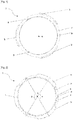
- the figure 1 shows an annular centering seal 1 according to the invention.
- the seal 1 is made in a circular form in one piece and comprises three centering wings 5 and a central axis A.
- the centering wings 5 extend outward from the gasket 1 away from the central axis. A.
- the central axis A is arranged in a plane perpendicular to the plane of the seal 1 and a point of this axis passes through the geometric center of the seal 1.
- the seal 1 comprises three notches 9 arranged on an interior wall 4, on the exterior side to seal 1.
- Seal 1 comprises an upper edge 7.
- the wings 5 have a width greater than that of the upper edge 7, the wings projecting from the seal.
- the seal 1 is made of elastic flexible material.
- the figure 2 represents the same annular centering seal 1 as at figure 1 .
- the seal 1 comprises three centering wings 5 arranged on the periphery of the inner wall 4 and an angle ⁇ of 120 °.
- the angle ⁇ is formed in the plane of the joint or in a plane parallel to the plane of the joint, and the center of this angle ⁇ is on the central axis A.
- the joint 1 comprises reference marks 14 in the form of a triangle and serving as d '' positioning indicators positioned in front of the same triangle visible on the cover of the figure 9 .
- the seal 1 comprises three stops 6 arranged projecting on the inner wall 4, and arranged alternately between the wings 5, with an angle ⁇ of 120 °
- the angle ⁇ is formed in the plane of the seal or in a plane parallel to the plane of the joint, and the center of this angle ⁇ is on the central axis A.
- the angle ⁇ and the angle ⁇ are in the same plane.
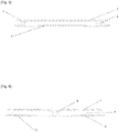
- the figure 3 shows a sectional view of the seal according to figure 1 .
- the wings 5 protrude from the upper edge 7 and have a width greater than that of the upper edge 7.
- the figure 4 shows a sectional view of the seal according to figure 1 .
- the figure 5 is a sectional view of the front profile of the seal according to figure 1 .
- the centering wing 5 is housed between two stops 6, equidistant from the geometric center of each stop 6.
- the figure 6 is a sectional view of the rear profile of the seal according to figure 1 .
- the stop 6 is housed between two centering wings 5 equidistant from the ends of each centering wing 5.
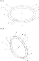
- the figure 7 is a perspective view from above of the seal according to figure 1 .
- the visible face of the upper edge 7 is housed against a cover 2. Its surface is smooth and flat in order to develop the maximum adhesion with the cover.
- the seal comprises three notches 9 which are spaces cooperating with ribs 8 of the cover 2.
- the figure 8 is a perspective view from below of the seal according to figure 1 .
- the seal comprises three marks 14 in the form of a triangle and serving as positioning indicators.
- the figure 9 is a perspective view of a cover 2 without a seal.
- the cover 2 has three marks 14 in the form of a triangle and serving as positioning indicators positioned in front of the same triangle visible on the seal 1.
- the cover 2 has three ribs 8 cooperating with the 3 notches 9 of the seal 1 . Only 2 ribs are visible on the figure 9 .
- the cover 2 comprises a projecting rim suitable for receiving a seal.
- the figure 10 represents the same annular centering joint 1 of the figure 1 arranged on a cover of a culinary appliance, the gasket 1 being in direct contact with the surface of the cover 2.
- This is a cover comprising a rope driving device.
- the cover 2 comprises a projecting rim on which the elastic seal 1 is placed.
- the diameter of the gasket 1 is of a dimension slightly smaller than that of the diameter of the projecting rim of the cover so as to tighten the gasket 1 and hold it on the cover by elastic pressure.
- the figure 11 shows a culinary appliance 3 of the mincer type with the cover shown on figure 9 .
- the culinary apparatus 3 comprises a glass bowl 10 forming a container, a work unit for cutting the food and a manually operated rope driving device housed in the cover 2.
- the apparatus 3 has an arm 11 for processing. food.
- the glass bowl 10 has a pivot point 12.
- the cover 2 has a drive point 13 of the working unit.
- the seal 1 is in position to play its role of canceling the play and re-centering the cover.
- the figure 12 is a perspective view of the culinary apparatus 3 of the figure 11 .
- the figure 13 is a sectional view of part of a second embodiment of a seal 1 according to the invention with a substantially U-shaped section.
- the seal 1 comprises an upper edge 7, an inner wall 4, a wing 5 of centering and a stop element 15.
- the centering wing 5 has a substantially cylindrical profile inclined relative to the inner wall 4.
- the wing 5 of centering has a foot 16 and a leading edge 17.
- this particular shape of the wing 5 gives it flexibility allowing it to bend when placing the cover on the bowl and allowing the cover to find its place optimal operation.
- the foot 16 has less flexibility than the leading edge 17, which allows the leading edge to act as a shock absorber or spring damping unwanted movements, in particular those of the cover.
- the wing 5 acts as a suspension of the bowl and cover assembly.
- the centering wing 5 is able to tilt and approach the stop element 15.
- the stop element 15 serves to limit the stroke. of the centering wing 5 and prevent the centering wing 5 from finding itself in a position where it could no longer play its role of shock absorber.
- the figures 14 and 15 are perspective views from above and from the side of the joint according to figure 13 .
- the figure 16 is a side sectional view of part of a third embodiment of a seal according to the invention with a variant of the stop element.
- the seal 1 has a stop element 15 of rectangular section, an upper edge 7, an inner wall 4, a centering wing 5.
- the centering wing 5 has a substantially cylindrical profile inclined relative to the inner wall 4.
- the centering wing 5 has a foot 16 and a leading edge 17.
- the figures 17 and 18 are perspective views from above and from the side of the joint according to figure 16 .
Landscapes
- Engineering & Computer Science (AREA)
- General Engineering & Computer Science (AREA)
- Mechanical Engineering (AREA)
- Food Science & Technology (AREA)
- Aviation & Aerospace Engineering (AREA)
- Acoustics & Sound (AREA)
- Physics & Mathematics (AREA)
- Life Sciences & Earth Sciences (AREA)
- Chemical & Material Sciences (AREA)
- Combustion & Propulsion (AREA)
- Wood Science & Technology (AREA)
- Zoology (AREA)
- Food-Manufacturing Devices (AREA)
- Cookers (AREA)
- Closures For Containers (AREA)
Abstract
Description
- La présente invention se rapporte au domaine culinaire et notamment à celui des appareils culinaires comprenant un dispositif d'entrainement à corde à commande manuelle et un bol en verre formant un récipient, tels que des hachoirs, des presse-purées, des extracteurs de jus, des essoreuses à salade ou des mélangeurs. Ces appareils sont actionnés manuellement, et sont donc non électriques, permettant de transmettre un mouvement d'une pièce à une autre pièce par traction d'un câble ou d'une corde.
- On notera que, dans ce document, les termes « longitudinal », « transversal », « perpendiculaire », « parallèle », « rotation », « horizontal », « vertical », « inférieur », « supérieur », « haut », « bas », « sécant », « coaxiaux », « convexe », « concave », « plan » employés pour décrire le dispositif, font référence à ce dispositif en situation d'usage, lorsqu'il est posé sur un plan horizontal.
- Il est connu des appareils culinaires avec joints en silicone compressibles qui réduisent l'espace entre un bol en verre et un couvercle. Ainsi, plus le jeu nécessaire pour l'assemblage est important, plus le joint silicone doit être compressible. Par le terme « jeu », il est généralement entendu au sens de l'invention une aisance de mouvement d'un élément due à un espace entre deux pièces ou deux surfaces.
- Un premier inconvénient de ces appareils culinaires avec un bol ou récipient en verre, est que le procédé de fabrication en série du verre implique des tolérances de fabrication plus importantes que le procédé d'injection plastique ou d'emboutissage du métal. Il s'en suit que les dimensions du bol en verre peuvent varier au cours de la fabrication de quelques millimètres entre chaque exemplaire du bol. Lorsqu'il est nécessaire de positionner un couvercle en plastique sur le bol en verre, l'assemblage est rendu difficile à cause de ces variations de dimensions du bol, qui comparativement se produisent de façon plus réduites avec un bol en plastique. En effet pour être certain que le couvercle rentre ou s'adapte sur le bol en verre, il faut prévoir le jeu nécessaire (c'est à dire qu'il y ait un minimum d'espace garanti entre le bol et le couvercle).
- Ce jeu nécessaire, qui est notable, apporte une perception de mauvaise qualité au produit car le couvercle peut bouger sur le bol. De plus, il se produit un bruit et des chocs quand le couvercle plastique ou le couvercle métal entre en contact avec le bol en verre, dus à cet important jeu qui est nécessaire pour l'assemblage. Le fait que le couvercle bouge et qu'il fasse du bruit participe également à une mauvaise perception de la qualité de construction de l'appareil.
- Un autre inconvénient de ces appareils culinaires avec un bol ou récipient en verre est qu'il est difficile d'aligner l'axe du couvercle sur l'axe de guidage central du bol en verre. En effet ces appareils comprennent un dispositif d'entrainement à corde à commande manuelle qui transmet un mouvement de rotation selon l'axe du couvercle à une unité de travail par traction d'un câble ou d'une corde à l'aide d'une roue d'entrainement, l'unité de travail étant le lieu de transformation des aliments. C'est généralement dans l'unité de travail que se trouvent les lames de coupe et l'arbre d'entrainement. Le dispositif d'entrainement à corde est logé dans le couvercle de l'appareil. L'unité de travail est logée dans le bol et centrée sur l'axe de guidage du bol en verre. Dans une conception idéale, l'axe de rotation du couvercle et l'axe de guidage central du bol en verre doivent être confondus. Le jeu nécessaire au montage du couvercle sur le bol, induit un désalignement plus ou moins important de ces deux axes. L'unité de travail qui devrait normalement travailler alignée sur les axes confondus, travaille en réalité en désaxé, sur des axes non confondus provoquant un désalignement des axes.
- De plus la pression exercée par les aliments, lors de leur transformation dans le bol, sur l'unité de travail à tendance à faire dévier l'axe de rotation du couvercle, induisant un désalignement par rapport à l'axe de guidage du bol en verre. La pression des aliments n'est pas continue et s'exerce à chaque traction de la corde.
- Un troisième inconvénient est que le tirage de la corde pour actionner le bras de traitement des aliments applique une force sur le couvercle dans la direction du tirage de la corde. Cette force ainsi appliquée à tendance à déporter le couvercle et son axe de façon régulière (à chaque tirage de corde) dans la direction du tirage de corde.
- Un quatrième inconvénient de ces appareils culinaires avec un bol ou récipient en verre est que lors de l'assemblage du couvercle sur le bras de travail et dans le bol, les jeux importants peuvent induire des difficultés d'assemblage et obliger l'utilisateur à viser l'entrainement du couvercle avec le bras de travail avec peu de visibilité.
- Tous les inconvénients cités ci-dessus induisent des efforts et des usures anormales des parties d'entrainement comme les pignons et les engrenages présents dans le couvercle, ce qui réduit considérablement la durée de vie de l'appareil.
- Le but de l'invention est de remédier aux inconvénients précités et d'améliorer l'assemblage du bol et du couvercle des appareils culinaires en créant un joint pour compenser le jeu entre le couvercle et le bol et également centrer l'axe du couvercle et l'axe du guidage du bol en verre afin qu'ils soient confondus. En effet le joint coopère avec le couvercle et sa nature souple et sa conception structurelle lui permettent de se compresser, ni trop, ni trop peu, pour compenser le jeu réel entre le couvercle et le bol.
- Avantageusement la combinaison des ailes de centrage et des butées apportent une solution pour compenser le jeu d'assemblage, pour centrer efficacement le couvercle sur le bol et pour maintenir l'axe du couvercle confondu avec l'axe du bol. Par le terme « centrage », il est entendu au sens de l'invention de positionner ou ramener une forme à l'intérieur d'une autre forme en son centre.
- Le joint selon l'invention présente l'avantage de pouvoir s'adapter facilement à toutes les différentes formes de couvercles et de bols et d'être fabriqué de façon indépendante du reste du couvercle de l'appareil culinaire. Avantageusement, le joint selon l'invention permet de centrer le couvercle et de limiter le décentrage du couvercle se produisant au cours de son utilisation. En effet le couvercle a tendance à se déporter et la conception du joint permet de limiter la déportation du couvercle dans toutes les directions.
- La présente invention a tout d'abord pour objet un joint de centrage annulaire en vue d'être disposé entre un couvercle et un bol, caractérisé en ce que le joint comprend un axe central perpendiculaire au plan du joint, une paroi intérieure, au moins une aile de centrage disposée radialement par rapport à l'axe central et au moins une butée disposée radialement par rapport à l'axe central.
- Le joint peut être disposé sur le couvercle et venir en contact avec le bol lors d'une phase d'accostage. Au cours de cette phase, le joint du couvercle se positionne côte à côte avec la partie supérieure du bol. Le joint peut coopérer avec le couvercle et peut être déformé et comprimé pour compenser un ensemble de mouvements indésirables qui sont principalement dans une direction généralement perpendiculaire à l'axe central. Ainsi le joint peut agir comme un organe de centrage qui ramène toujours le couvercle au centre.
- Le joint de centrage annulaire peut se présenter sous la forme d'une bague circulaire ou rectangulaire.
- Selon une autre caractéristique de l'invention, la ou les ailes et la ou les butées peuvent être disposées sur la paroi intérieure, de préférence dans un même plan. De préférence la ou les ailes peuvent être disposées à l'extrémité de la paroi intérieure. L'aile de centrage présente un pied à son extrémité côté paroi intérieure et un bord d'attaque à son autre extrémité. Le pied est le point d'attache à la paroi intérieure et le bord d'attaque est l'extrémité libre. Il est envisagé que la section des ailes de centrage présente un aminci où la partie la plus épaisse serait au niveau du pied, côte paroi intérieure, et la partie la plus mince serait vers l'extérieur du joint, au niveau du bord d'attaque. Le profil du corps de l'aile de centrage peut présenter une section évolutive qui va en diminuant du pied de l'aile jusqu'au bord d'attaque. Avantageusement, cette forme particulière des ailes permet à l'aile d'agir comme amortisseur ou ressort qui vient amortir les mouvements indésirables, en particulier ceux du couvercle. L'aile agit comme une suspension de l'ensemble bol et couvercle.
- Selon une autre caractéristique de l'invention, la ou les ailes et les butées peuvent être disposées radialement dans le plan du joint par rapport à l'axe central. La ou les butées peuvent coopérer avec le bord du bol pour compenser un ensemble de mouvements indésirables qui sont principalement dans une direction généralement perpendiculaire à l'axe central.
- Selon une autre caractéristique de l'invention, la ou les ailes et les butées peuvent être disposées radialement dans un même plan par rapport à l'axe central.
- De préférence, la ou les ailes et la paroi intérieure peuvent former un angle droit, au repos lorsque que le joint n'est soumis à aucune compression. Ainsi, le bol est maintenu à une distance constante du couvercle.
- Selon une autre caractéristique de l'invention et en cas de pluralité d'ailes de centrage, les ailes peuvent être espacées et former un angle a, identique ou différent. De préférence tous les angles a sont identiques entre eux, mais il peut être envisagé que les ailes de centrage soient disposées de manière non symétrique sur la paroi intérieure. Il peut aussi être envisagé que les ailes de centrage soient disposées de manière contiguë, c'est-à-dire juxtaposées et se touchent.
- Selon une autre caractéristique de l'invention, l'angle α est disposé dans le plan du joint ou dans un plan parallèle au plan du joint, et le centre de l'angle α est sur l'axe central. Avantageusement, l'angle α est situé dans un plan perpendiculaire à l'axe central.
- Selon une autre caractéristique de l'invention, l'angle α n'existe pas lorsqu'il y a une seule aile de centrage. Dans ce cas, l'aile de centrage est disposée sur toute la périphérie de la paroi intérieure.
- Selon une autre caractéristique de l'invention, les ailes de centrage sont disposées en vis-à-vis lorsqu'il y 2 ailes de centrage, l'angle α étant de 180°. Selon une autre caractéristique de l'invention, l'angle α est de 120° lorsqu'il y a 3 ailes de centrage.
- Selon une autre caractéristique de l'invention, l'angle α est de 90° lorsqu'il y a 4 ailes de centrage. Ainsi en faisant varier le nombre d'ailes de centrage et la valeur de l'angle a, il est possible d'adapter la meilleure performance d'annulation du jeu et de recentrage du couvercle en fonction des différentes formes du bol et du couvercle. Avantageusement, cette flexibilité dans la répartition des ailes de centrage, permet une grande adaptabilité.
- Selon une autre caractéristique de l'invention, la ou les ailes de centrage peuvent s'étendre dans un plan orienté vers l'extérieur du joint par rapport à l'axe central, en périphérie du joint. Il est entendu que l'extérieur du joint est la partie du joint du côté du bol en verre, et l'intérieur du joint est la partie du côté de l'axe central du joint.
- Selon une autre caractéristique de l'invention, le joint peut comprendre au moins une butée s'étendant vers l'extérieur du joint par rapport à l'axe central. Avantageusement, les butées du joint selon l'invention permettent de centrer le couvercle et de limiter le décentrage du couvercle se produisant au cours de son utilisation. En effet le couvercle a tendance à se déporter et les butées viennent éviter la déportation excessive du couvercle dans toutes les directions, généralement dans une direction perpendiculaire à l'axe central.
- Selon une autre caractéristique de l'invention, le joint peut comprendre des butées en saillie par rapport à la paroi intérieure du joint et s'étendant vers l'extérieur du joint par rapport à l'axe central, pour compenser un ensemble de mouvements indésirables qui sont principalement dans une direction généralement perpendiculaire à l'axe central.
- Selon une autre caractéristique de l'invention et en cas de pluralité de butées, les butées peuvent être espacées et former un angle β, tous les angles β étant identiques entre eux. Avantageusement, l'angle β est situé dans un plan perpendiculaire à l'axe central. Ainsi l'action des butées permet généralement de garder l'axe du bras de traitement des aliments dans un plan perpendiculaire à son point de pivot situé dans la partie inférieure du bol en verre et à son point d'entraînement situé dans le couvercle, pour ne pas endommager les pignons et/ou engrenages situés dans le couvercle.
- Avantageusement la combinaison de l'action des ailes de centrage et des butées permet au couvercle de s'auto centrer, c'est-à-dire sans l'aide de l'utilisateur. Les ailes de centrage exercent un effort contre la paroi du bol qui permet au couvercle de s'auto centrer. En cas de force appliquée sur le couvercle, le couvercle se décentre mais accepte un décentrage limité grâce à la ou les butées. Puis avec la diminution de l'effort ou en absence d'effort, les ailes de centrage ramènent le couvercle au centre. L'auto centrage a lieu de préférence sur le retour de la corde de traction, après le tirage de la corde, quand il n'y a plus de force transmise à l'arbre d'entrainement par le tirage de la corde.
- Selon une autre caractéristique de l'invention, l'angle β peut être dans le plan du joint et le centre de l'angle β est sur l'axe central.
- Selon une autre caractéristique de l'invention, l'angle β peut être de 360° lorsqu'il y a 1 butée.
- Selon une autre caractéristique de l'invention, l'angle β peut être de 180° lorsqu'il y a 2 butées.
- Selon une autre caractéristique de l'invention, l'angle β peut être de 120° lorsqu'il y a 3 butées.
- Selon une autre caractéristique de l'invention, l'angle β peut être de 90° lorsqu'il y a 4 butées.
- Selon une autre caractéristique de l'invention, les ailes de centrage et les butées sont disposées en alternance sur la paroi intérieure du joint, de préférence en alternance régulière sur la paroi intérieure, c'est-à-dire une butée puis une aile centrage puis une buté.
- Selon une autre caractéristique de l'invention, au moins une butée du joint sera positionnée dans l'axe du tirage de corde. Ainsi la distance de déport de l'axe du couvercle sera contrôlée, si l'axe de tirage de la corde se trouvait entre 2 butées le déport pourrait être plus important.
- Selon une autre caractéristique de l'invention, le joint peut présenter une section en forme de L sur tout ou partie de la section.
- Selon une autre caractéristique de l'invention, le joint peut comprendre en outre un bord supérieur disposé en saillie du joint, le joint présentant ainsi une section en U, en tout ou partie de la section. Ainsi la présence d'un bord supérieur permet d'augmenter les capacités d'adhérence du joint au couvercle afin qu'il soit fixe sur le couvercle et ne glisse pas. Ainsi cela permet d'augmenter les capacités d'amortissement et de guidage du joint
- Selon une autre caractéristique de l'invention, le bord supérieur peut s'étendre dans un plan orienté vers l'extérieur du joint par rapport à l'axe central, en périphérie du joint. Le bord forme ainsi une couronne.
- Selon une autre caractéristique de l'invention, le bord supérieur et la ou les ailes de centrage peuvent être compris chacun dans 2 plans parallèles distincts. De préférence, le bord présente une largeur inférieure à la largeur de la ou des ailes de centrage, ce qui augmente la surface de contact avec le bol et favorise l'appui de la ou des ailes de centrage sur le bol et le guidage du couvercle. De préférence, la ou les ailes de centrage présentent une largeur supérieure à la largeur du bord.
- Selon une autre caractéristique de l'invention, le bord supérieur et la ou les ailes de centrage peuvent être disposés en vis-à-vis, formant ainsi une gorge avec la paroi intérieure.
- Selon une autre caractéristique de l'invention, le joint est flexible. Il est réalisé en matériau déformable. De préférence, il est réalisé en une seule pièce par moulage.
- Selon une autre caractéristique de l'invention, le joint peut être idéalement fabriqué dans une dureté shore comprise de 40 Shore A à 80 Shore A, de préférence de 60 Shore A à 80 Shore A.
- Selon une autre caractéristique de l'invention, le joint peut être idéalement fabriqué dans une matière souple comme par exemple le silicone ou un thermoplastique élastomère.
- Selon une autre caractéristique de l'invention, le joint peut comprendre en outre un dispositif de positionnement du joint sur le couvercle.
- Selon une autre caractéristique de l'invention, le dispositif de positionnement peut être une nervure ou une encoche coopérant avec l'encoche ou la nervure disposée en vis-à-vis sur le couvercle. Ainsi, le dispositif de positionnement permet aisément d'orienter le joint par rapport au couvercle. En effet, le joint étant amovible afin de pouvoir être nettoyé plus facilement, il est important de le repositionner correctement pour optimiser son action. De préférence, le dispositif de positionnement comprend une ou des encoches disposées sur le joint et une ou des nervures disposées en vis-à-vis sur le couvercle. Il est à noter qu'une nervure d'un élément coopère avec une encoche de l'autre élément.
- Selon une autre caractéristique de l'invention, un repère peut être ajouté sur le couvercle et/ou le joint pour visualiser plus facilement l'encoche du joint en vis-à-vis de la nervure du couvercle. Ce repère peut servir d'indicateur de positionnement, ce qui facilitera l'usage du joint par un utilisateur. De préférence, ce repère peut être un signe géométrique comme un triangle. Selon une autre caractéristique de l'invention, au moins un repère peut être aligné dans l'axe de tirage de la corde.
- Selon une autre caractéristique de l'invention, le joint selon l'invention comprend un élément d'arrêt, servant à limiter la course de l'aile de centrage et ainsi garantir le bon fonctionnement du joint. L'élément d'arrêt évite que l'aile de centrage ne se retrouve dans une position où elle ne pourrait plus jouer son rôle d'amortisseur. De préférence, l'élément d'arrêt vient limiter la course du bord d'attaque de l'aile de centrage. De préférence, l'élément d'arrêt est un élément d'arrêt de l'aile de centrage, en particulier du bord d'attaque de l'aile de centrage.
- Un autre objet de l'invention est un couvercle d'un appareil culinaire comprenant le joint selon l'invention.
- Un autre objet de l'invention est un appareil culinaire comprenant le couvercle selon l'invention. De préférence, l'appareil culinaire est un appareil non électrique comprenant un dispositif d'entrainement à corde à commande manuelle et un bol en verre formant un récipient, tels que des hachoirs, des presse-purées, des extracteurs de jus, des essoreuses à salade ou des mélangeurs.
- On comprendra mieux les buts, aspects et avantages de la présente invention, d'après la description donnée ci-après de modes particuliers de réalisation de l'invention présentés à titre d'exemples non limitatifs, en se référant aux dessins annexés dans lesquels :
- [
Fig. 1 ] Lafigure 1 est une vue en coupe de dessus d'un premier exemple de réalisation d'un joint selon l'invention avec une section en U. - [
Fig. 2 ] Lafigure 2 est une vue en coupe de dessous du joint selon lafigure 1 . - [
Fig. 3 ] Lafigure 3 est une vue en coupe du profil droit du joint selon lafigure 1 . - [
Fig. 4 ] Lafigure 4 est une vue en coupe du profil gauche du joint selon lafigure 1 . - [
Fig. 5 ] Lafigure 5 est une vue en coupe du profil de devant du joint selon lafigure 1 . - [
Fig. 6 ] Lafigure 6 est une vue en coupe du profil arrière du joint selon lafigure 1 . - [
Fig. 7 ] Lafigure 7 est une vue en perspective de dessus du joint selon lafigure 1 . - [
Fig. 8 ] Lafigure 8 est une vue en perspective de dessous du joint selon lafigure 1 . - [
Fig. 9 ] Lafigure 9 est une vue en perspective de dessous du couvercle selon l'invention sans le joint. - [
Fig. 10 ] Lafigure 10 est une vue en perspective de dessous du couvercle selon lafigure 9 comprenant le joint selon lafigure 1 , et mis en oeuvre dans l'appareil desfigures 11 et 12 . - [
Fig. 11 ] Lafigure 11 est une vue en coupe d'un appareil culinaire du type hachoir comprenant le couvercle selon lafigure 10 installé sur le bol. - [
Fig. 12 ] Lafigure 12 est une vue en perspective de l'appareil culinaire selon lafigure 11 . - [
Fig. 13 ] Lafigure 13 est une vue en coupe de profil d'une partie d'un second exemple de réalisation d'un joint selon l'invention avec élément d'arrêt et une section en U. - [
Fig. 14 ] Lafigure 14 est une vue en perspective de dessus du joint selon lafigure 13 . - [
Fig. 15 ] Lafigure 15 est une vue en perspective de côté du joint selon lafigure 13 . - [
Fig. 16 ] Lafigure 16 est une vue en coupe de profil d'une partie d'un troisième exemple de réalisation d'un joint selon l'invention avec un autre exemple d'élément d'arrêt et une section en U. - [
Fig. 17 ] Lafigure 17 est une vue en perspective de dessus du joint selon lafigure 16 . - [
Fig. 18 ] Lafigure 18 est une vue en perspective de côté du joint selon lafigure 16 . - La
figure 1 représente un joint 1 de centrage annulaire selon l'invention. Le joint 1 est réalisé sous une forme circulaire en une seule pièce et comprend trois ailes 5 de centrage et un axe central A. Les ailes 5 de centrage s'étendent vers l'extérieur du joint 1 en s'éloignant de l'axe central A. L'axe central A est disposé dans un plan perpendiculaire au plan du joint 1 et un point de cet axe passe par le centre géométrique du joint 1. Le joint 1 comprend trois encoches 9 disposées sur une paroi intérieure 4, du côté extérieur au joint 1. Le joint 1 comprend un bord supérieur 7. Les ailes 5 présentent une largeur supérieure à celle du bord supérieur 7, les ailes débordant du joint. Le joint 1 est en matière souple élastique. - La
figure 2 représente le même joint 1 de centrage annulaire qu'à lafigure 1 . Le joint 1 comprend trois ailes 5 de centrage disposées sur la périphérie de la paroi intérieure 4 et un angle α de 120°. L'angle α est formé dans le plan du joint ou dans un plan parallèle au plan du joint, et le centre de cet angle α est sur l'axe central A. le joint 1 comprend des repères 14 sous forme de triangle et servant d'indicateurs de positionnement venant se positionner en face d'un même triangle visible sur le couvercle de lafigure 9 . Le joint 1 comprend trois butées 6 disposées en saillie sur la paroi intérieure 4, et disposées en alternance entre les ailes 5, avec un angle β de 120° L'angle β est formé dans le plan du joint ou dans un plan parallèle au plan du joint, et le centre de cet angle β est sur l'axe central A. L'angle α et l'angle β sont dans un même plan. - La
figure 3 représente une vue en coupe du joint selon lafigure 1 . Les ailes 5 débordent du bord supérieur 7 et présentent une largeur supérieure à celle du bord supérieur 7. - La
figure 4 représente une vue en coupe du joint selon lafigure 1 . - La
figure 5 est une vue en coupe du profil de devant du joint selon lafigure 1 . L'aile 5 de centrage est logée entre deux butées 6, à équidistance du centre géométrique de chaque butée 6. - La
figure 6 est une vue en coupe du profil arrière du joint selon lafigure 1 . La butée 6 est logée entre deux ailes 5 de centrage à équidistance des extrémités de chaque aile 5 de centrage. - La
figure 7 est une vue en perspective de dessus du joint selon lafigure 1 . La face visible du bord supérieur 7 vient se loger contre un couvercle 2. Sa surface est lisse et plane afin de développer le maximum d'adhérence avec le couvercle. Le joint comprend trois encoches 9 qui sont des espaces coopérant avec des nervures 8 du couvercle 2. - La
figure 8 est une vue en perspective de dessous du joint selon lafigure 1 . Le joint comprend trois repères 14 sous forme de triangle et servant d'indicateurs de positionnement. - La
figure 9 est une vue en perspective d'un couvercle 2 sans joint. Le couvercle 2 présente trois repères 14 sous forme de triangle et servant d'indicateurs de positionnement venant se positionner en face d'un même triangle visible sur le joint 1. Le couvercle 2 présente trois nervures 8 coopérant avec les 3 encoches 9 du joint 1. Seules 2 nervures sont visibles sur lafigure 9 . Le couvercle 2 comprend un rebord saillant apte à recevoir un joint. - La
figure 10 représente le même joint 1 de centrage annulaire de lafigure 1 disposé sur un couvercle d'un appareil culinaire, le joint 1 étant en contact direct avec la surface du couvercle 2. Il s'agit d'un couvercle comprenant un dispositif d'entrainement à corde. Le couvercle 2 comprend un rebord saillant sur lequel est disposé le joint 1 élastique. Le diamètre du joint 1 est d'une dimension légèrement inférieure à celle du diamètre du rebord saillant du couvercle de manière à venir tendre le joint 1 et le maintenir sur le couvercle par pression élastique. Lorsque le couvercle 2 avec le joint 1 est positionné sur un bol 10 d'un appareil, il se produit une déformation des ailes 5 ce qui évite la formation d'un interstice entre le bol 10 et le couvercle 2. Les ailes 5 se replient et viennent compenser le jeu entre le couvercle 2 et le bol 10 et également centrer l'axe du couvercle et l'axe du guidage du bol 10 en verre afin qu'ils soient confondus. - La
figure 11 représente un appareil 3 culinaire du type hachoir avec le couvercle représenté à lafigure 9 . L'appareil 3 culinaire comprend un bol 10 en verre formant un récipient, une unité de travail pour découper les aliments et un dispositif d'entrainement à corde à commande manuelle logé dans le couvercle 2. L'appareil 3 présente un bras 11 de traitement des aliments. Le bol 10 en verre présente un point de pivot 12. Le couvercle 2 présente un point d'entrainement 13 de l'unité de travail. Le joint 1 est en position pour jouer son rôle d'annulation du jeu et de recentrage du couvercle. - La
figure 12 est une vue en perspective de l'appareil 3 culinaire de lafigure 11 . Lafigure 13 est une vue en coupe d'une partie d'un second exemple de réalisation d'un joint 1 selon l'invention avec une section sensiblement en U. Le joint 1 comprend un bord supérieur 7, une paroi intérieure 4, une aile 5 de centrage et un élément d'arrêt 15. L'aile 5 de centrage présente un profil sensiblement cylindrique incliné par rapport à la paroi intérieure 4. L'aile 5 de centrage présente un pied 16 et un bord d'attaque 17. Avantageusement, cette forme particulière de l'aile 5 lui confère une souplesse lui permettant de s'infléchir lors de la pose du couvercle sur le bol et permettant au couvercle de trouver sa place optimale de fonctionnement. Le pied 16 présente moins de souplesse que le bord d'attaque 17, ce qui permet au bord d'attaque d'agir comme amortisseur ou ressort amortissant les mouvements indésirables, en particulier ceux du couvercle. L'aile 5 agit comme une suspension de l'ensemble bol et couvercle. Lors de l'accostage du couvercle 2 sur le bol 10, l'aile 5 de centrage est apte à s'incliner et à se rapprocher de l'élément d'arrêt 15. L'élément d'arrêt 15 sert à limiter la course de l'aile 5 de centrage et éviter que l'aile 5 de centrage ne se retrouve dans une position où elle ne pourrait plus jouer son rôle d'amortisseur. - Les
figures 14 et 15 sont des vues en perspective de dessus et de côté du joint selon lafigure 13 . - La
figure 16 est une vue en coupe de profil d'une partie d'un troisième exemple de réalisation d'un joint selon l'invention avec une variante de l'élément d'arrêt. Le joint 1 présente un élément d'arrêt 15 de section rectangulaire, un bord supérieur 7, une paroi intérieure 4, une aile 5 de centrage. L'aile 5 de centrage présente un profil sensiblement cylindrique incliné par rapport à la paroi intérieure 4. L'aile 5 de centrage présente un pied 16 et un bord d'attaque 17. - Les
figures 17 et18 sont des vues en perspective de dessus et de côté du joint selon lafigure 16 .
Claims (15)
- Joint (1) de centrage annulaire en vue d'être disposé entre un couvercle (2) et un bol (10), caractérisé en ce que le joint comprend un axe central A perpendiculaire au plan du joint, une paroi intérieure (4), au moins une aile (5) de centrage disposée radialement par rapport à l'axe central A et au moins une butée (6) disposée radialement par rapport à l'axe central A et en saillie par rapport à la paroi intérieure (4), la butée (6) s'étendant vers l'extérieur du joint (1) par rapport à l'axe central A.
- Joint (1) selon la revendication 1 caractérisé en ce que la ou les ailes (5) et la ou les butées (6) sont disposées sur la paroi intérieure (4).
- Joint (1) selon l'une des revendications précédentes caractérisé en ce que la ou les ailes (5) et les butées (6) sont disposées radialement dans le plan du joint (1) par rapport à l'axe central A.
- Joint (1) selon l'une des revendications précédentes caractérisé en ce qu'en cas de pluralité d'ailes (5) de centrage, les ailes sont espacées et forment un angle a, identique ou différent.
- Joint (1) selon l'une des revendications précédentes caractérisé en ce que l'angle α est disposé dans le plan du joint (1) ou dans un plan parallèle au plan du joint (1), et le centre de l'angle α est sur l'axe central A.
- Joint (1) selon l'une des revendications précédentes caractérisé en ce que la ou les ailes (5) de centrage s'étendent dans un plan orienté vers l'extérieur du joint (1) par rapport à l'axe central A.
- Joint (1) selon l'une des revendications précédentes caractérisé en ce qu'en cas de pluralité de butées (6), les butées (6) sont espacées et forment un angle β, tous les angles β étant identiques entre eux.
- Joint (1) selon l'une des revendications précédentes caractérisé en ce que le joint (1) présente une section en forme de L sur tout ou partie de la section.
- Joint (1) selon l'une des revendications précédentes caractérisé en ce qu'il comprend en outre un bord supérieur (7) disposé en saillie du joint (1), le joint présentant ainsi une section en U, en tout ou partie de la section.
- Joint (1) selon la revendication 9 caractérisé en ce que le bord supérieur (7) et la ou les ailes (5) de centrage sont compris chacun dans 2 plans parallèles distincts.
- Joint (1) selon la revendication 9 caractérisé en ce que le bord supérieur (7) et la ou les ailes (5) de centrage sont disposés en vis-à-vis, formant ainsi une gorge avec la paroi intérieure (4).
- Joint (1) selon l'une des revendications précédentes caractérisé en ce qu'il comprend en outre un dispositif de positionnement du joint sur le couvercle.
- Joint (1) selon la revendication 12 caractérisé en ce que le dispositif de positionnement est une nervure (8) ou une encoche (9) coopérant avec l'encoche (9) ou la nervure (8) disposée en vis-à-vis sur le couvercle.
- Couvercle d'un appareil culinaire comprenant le joint (1) selon l'une des revendications précédentes.
- Appareil culinaire comprenant le couvercle de la revendication 14.
Applications Claiming Priority (1)
| Application Number | Priority Date | Filing Date | Title |
|---|---|---|---|
| FR1910318A FR3101124B1 (fr) | 2019-09-19 | 2019-09-19 | Joint de centrage pour couvercle d’appareil culinaire |
Publications (2)
| Publication Number | Publication Date |
|---|---|
| EP3795867A1 true EP3795867A1 (fr) | 2021-03-24 |
| EP3795867B1 EP3795867B1 (fr) | 2025-09-03 |
Family
ID=69024383
Family Applications (1)
| Application Number | Title | Priority Date | Filing Date |
|---|---|---|---|
| EP20195143.1A Active EP3795867B1 (fr) | 2019-09-19 | 2020-09-08 | Joint de centrage pour couvercle d'appareil culinaire |
Country Status (3)
| Country | Link |
|---|---|
| EP (1) | EP3795867B1 (fr) |
| CN (1) | CN112515499B (fr) |
| FR (1) | FR3101124B1 (fr) |
Citations (5)
| Publication number | Priority date | Publication date | Assignee | Title |
|---|---|---|---|---|
| US20150056903A1 (en) * | 2013-08-22 | 2015-02-26 | Noritz America Corporation | Exhaust adapter, exhaust structure for water heater, and method for installing exhaust adapter |
| US20150159788A1 (en) * | 2013-12-10 | 2015-06-11 | GM Global Technology Operations LLC | Sealing device for a vehicle |
| CN206284998U (zh) * | 2016-10-19 | 2017-06-30 | 江门市西屋厨房小家电有限公司 | 一种料理机杯盖的密封结构 |
| CN206637034U (zh) * | 2017-04-18 | 2017-11-14 | 广东美的生活电器制造有限公司 | 杯盖密封圈和料理机 |
| CN207202780U (zh) * | 2017-04-01 | 2018-04-10 | 九阳股份有限公司 | 密封可靠的食品加工机 |
Family Cites Families (19)
| Publication number | Priority date | Publication date | Assignee | Title |
|---|---|---|---|---|
| US3112114A (en) * | 1960-09-28 | 1963-11-26 | William H Jacobs | Sealing gasket for beverage dispensers |
| US3339934A (en) * | 1965-02-23 | 1967-09-05 | Jet Spray Cooler Inc | Sealing grommet |
| US4311317A (en) * | 1979-08-20 | 1982-01-19 | Bartels Harold U | Lip and radial seal |
| WO1994027880A1 (fr) * | 1993-05-21 | 1994-12-08 | Beierling, Uwe | Corps creux a couvercle a fermeture amovible |
| FR2862853B1 (fr) * | 2003-11-27 | 2006-09-15 | Seb Sa | Appareil de cuisson sous pression muni d'un dispositif de securite a la surpression, et joint d'etancheite pour un tel appareil |
| FR2919702A1 (fr) * | 2007-08-02 | 2009-02-06 | Dominique Leroy Production Soc | Joint de fermeture et d'etancheite |
| FR2922428A1 (fr) * | 2007-10-23 | 2009-04-24 | Seb Sa | Autocuiseur pourvu d'un systeme de securite a la surpression |
| US9188260B2 (en) * | 2008-08-01 | 2015-11-17 | Nibco Inc. | Crimp evident seal |
| US8814174B2 (en) * | 2010-07-08 | 2014-08-26 | Uchiyama Manufacturing Corp. | Rubber gasket and seal structure using the same |
| ITBS20110087A1 (it) * | 2011-06-15 | 2012-12-16 | Flaem Nuova Spa | Contenitori per la marinatura e/o conservazione di prodotti sottovuoto |
| US20150201792A1 (en) * | 2012-07-16 | 2015-07-23 | Tuttoespresso S.R.L. | Capsule with improved sealing element |
| JP2014084128A (ja) * | 2012-10-22 | 2014-05-12 | Toppan Printing Co Ltd | 蓋材およびそれを用いた密封容器 |
| US20140134304A1 (en) * | 2012-11-15 | 2014-05-15 | Sunbeam Products, Inc. | Culinary Systems and Methods for Making a Mixed Food Item |
| JP3187897U (ja) * | 2013-10-10 | 2013-12-19 | 鐙順實業股▲分▼有限公司 | 組合せ式ジューサー |
| FR3019022B1 (fr) * | 2014-03-26 | 2017-02-24 | Seb Sa | Appareil de cuisson d'aliments sous pression a baionnettes inversees et methode de fabrication afferente |
| FR3049840B1 (fr) * | 2016-04-08 | 2019-04-05 | Seb S.A. | Autocuiseur pourvu d'une ouverture de couvercle |
| US10285522B2 (en) * | 2016-08-17 | 2019-05-14 | Impel Studio LLC | Travel vessel for beverages |
| CN208658695U (zh) * | 2017-12-29 | 2019-03-29 | 佛山市顺德区美的电热电器制造有限公司 | 用于烹饪器具的泄压装置和烹饪器具 |
| JP7440205B2 (ja) * | 2018-07-10 | 2024-02-28 | Nok株式会社 | ガスケット及び封止構造 |
-
2019
- 2019-09-19 FR FR1910318A patent/FR3101124B1/fr active Active
-
2020
- 2020-09-08 EP EP20195143.1A patent/EP3795867B1/fr active Active
- 2020-09-17 CN CN202010978523.9A patent/CN112515499B/zh active Active
Patent Citations (5)
| Publication number | Priority date | Publication date | Assignee | Title |
|---|---|---|---|---|
| US20150056903A1 (en) * | 2013-08-22 | 2015-02-26 | Noritz America Corporation | Exhaust adapter, exhaust structure for water heater, and method for installing exhaust adapter |
| US20150159788A1 (en) * | 2013-12-10 | 2015-06-11 | GM Global Technology Operations LLC | Sealing device for a vehicle |
| CN206284998U (zh) * | 2016-10-19 | 2017-06-30 | 江门市西屋厨房小家电有限公司 | 一种料理机杯盖的密封结构 |
| CN207202780U (zh) * | 2017-04-01 | 2018-04-10 | 九阳股份有限公司 | 密封可靠的食品加工机 |
| CN206637034U (zh) * | 2017-04-18 | 2017-11-14 | 广东美的生活电器制造有限公司 | 杯盖密封圈和料理机 |
Also Published As
| Publication number | Publication date |
|---|---|
| CN112515499A (zh) | 2021-03-19 |
| CN112515499B (zh) | 2025-10-21 |
| FR3101124A1 (fr) | 2021-03-26 |
| EP3795867B1 (fr) | 2025-09-03 |
| FR3101124B1 (fr) | 2022-12-16 |
Similar Documents
| Publication | Publication Date | Title |
|---|---|---|
| EP3088970B1 (fr) | Montre destinée à être montée sur un support amovible | |
| EP3200645B1 (fr) | Pot de cosmétique comportant un couvercle à élément d'accrochage basculant | |
| EP1283377B1 (fr) | Support antivibratoire hydraulique | |
| EP1321080B1 (fr) | Couvercle pour appareil de cuisson sous pression à mâchoires allégées et appareil de cuisson comportant un tel couvercle | |
| EP3118070B1 (fr) | Organe pour un système de connexion d'un balai d'essuie-glace | |
| EP3047074B1 (fr) | Système mécanique comprenant un dispositif de liaison entre une pièce d'usure et son support, et godet d'engin de travaux publics | |
| EP3624657B1 (fr) | Appareil de mixage et de melange pour des preparations alimentaires liquides ou pateuses equipe d'un dispositif de verrouillage des couteaux sur le bol | |
| EP2529902A1 (fr) | Outil de coupe d'aliments en morceaux | |
| EP3112227B1 (fr) | Adaptateur pour relier un balai d'essuie-glace à un bras d'entraînement | |
| EP3795867B1 (fr) | Joint de centrage pour couvercle d'appareil culinaire | |
| EP3658790B1 (fr) | Un système de cage écrou comportant une cage écrou et un support sur lequel la cage est destinée à être montée | |
| EP3251905A1 (fr) | Adaptateur de raccordement de l'extrémité libre d'un bras d'essuie-glace, ensemble comportant un tel adaptateur et un bras d'essuie-glace | |
| FR3047528A1 (fr) | Dispositif de progressivite pour disque de friction d'embrayage et disque de friction integrant un tel dispositif | |
| EP2937027A1 (fr) | Appareil electromenager de preparation culinaire comportant un recipient amovible pouvant etre dispose sur un boitier par un simple mouvement de translation | |
| FR3002335A1 (fr) | Dispositif de commande avec tenue a l'arrachement | |
| EP2716188B1 (fr) | Appareil de cuisson d'aliments sous pression a couvercle allege | |
| EP2239358B1 (fr) | Dispositif d'assemblage, ensemble de deux pièces assemblées par un tel dispositif et lame de machine de formation de la foule comprenant un tel ensemble | |
| EP2633775B1 (fr) | Bracelet articulé | |
| EP2945028A1 (fr) | Palier antichoc | |
| EP4124520A1 (fr) | Dispositif de connexion entre balai d' essuyage et bras d' entraînement | |
| FR3040154B1 (fr) | Adaptateur de balai d'essuie-glace et balai d'essuie-glace ainsi equipe | |
| FR2861818A1 (fr) | Manchon pour vis | |
| FR3058305B1 (fr) | Dispositif de traitement d'aliments muni d'un pied d'appui | |
| FR2584786A1 (fr) | Montage de butee de debrayage et butee de debrayage propre a un tel montage | |
| EP3560396B1 (fr) | Dispositif de fixation d'un feutre d'essuyage et ensemble qui le comporte |
Legal Events
| Date | Code | Title | Description |
|---|---|---|---|
| PUAI | Public reference made under article 153(3) epc to a published international application that has entered the european phase |
Free format text: ORIGINAL CODE: 0009012 |
|
| STAA | Information on the status of an ep patent application or granted ep patent |
Free format text: STATUS: THE APPLICATION HAS BEEN PUBLISHED |
|
| AK | Designated contracting states |
Kind code of ref document: A1 Designated state(s): AL AT BE BG CH CY CZ DE DK EE ES FI FR GB GR HR HU IE IS IT LI LT LU LV MC MK MT NL NO PL PT RO RS SE SI SK SM TR |
|
| AX | Request for extension of the european patent |
Extension state: BA ME |
|
| STAA | Information on the status of an ep patent application or granted ep patent |
Free format text: STATUS: REQUEST FOR EXAMINATION WAS MADE |
|
| 17P | Request for examination filed |
Effective date: 20210923 |
|
| RBV | Designated contracting states (corrected) |
Designated state(s): AL AT BE BG CH CY CZ DE DK EE ES FI FR GB GR HR HU IE IS IT LI LT LU LV MC MK MT NL NO PL PT RO RS SE SI SK SM TR |
|
| STAA | Information on the status of an ep patent application or granted ep patent |
Free format text: STATUS: EXAMINATION IS IN PROGRESS |
|
| 17Q | First examination report despatched |
Effective date: 20220629 |
|
| GRAP | Despatch of communication of intention to grant a patent |
Free format text: ORIGINAL CODE: EPIDOSNIGR1 |
|
| STAA | Information on the status of an ep patent application or granted ep patent |
Free format text: STATUS: GRANT OF PATENT IS INTENDED |
|
| INTG | Intention to grant announced |
Effective date: 20250530 |
|
| GRAS | Grant fee paid |
Free format text: ORIGINAL CODE: EPIDOSNIGR3 |
|
| GRAA | (expected) grant |
Free format text: ORIGINAL CODE: 0009210 |
|
| STAA | Information on the status of an ep patent application or granted ep patent |
Free format text: STATUS: THE PATENT HAS BEEN GRANTED |
|
| AK | Designated contracting states |
Kind code of ref document: B1 Designated state(s): AL AT BE BG CH CY CZ DE DK EE ES FI FR GB GR HR HU IE IS IT LI LT LU LV MC MK MT NL NO PL PT RO RS SE SI SK SM TR |
|
| REG | Reference to a national code |
Ref country code: CH Ref legal event code: EP |
|
| REG | Reference to a national code |
Ref country code: DE Ref legal event code: R096 Ref document number: 602020057885 Country of ref document: DE |
|
| REG | Reference to a national code |
Ref country code: IE Ref legal event code: FG4D Free format text: LANGUAGE OF EP DOCUMENT: FRENCH |
|
| PGFP | Annual fee paid to national office [announced via postgrant information from national office to epo] |
Ref country code: FR Payment date: 20250930 Year of fee payment: 6 |
|
| REG | Reference to a national code |
Ref country code: NL Ref legal event code: MP Effective date: 20250903 |
|
| PGFP | Annual fee paid to national office [announced via postgrant information from national office to epo] |
Ref country code: DE Payment date: 20251015 Year of fee payment: 6 |
|
| PG25 | Lapsed in a contracting state [announced via postgrant information from national office to epo] |
Ref country code: NO Free format text: LAPSE BECAUSE OF FAILURE TO SUBMIT A TRANSLATION OF THE DESCRIPTION OR TO PAY THE FEE WITHIN THE PRESCRIBED TIME-LIMIT Effective date: 20251203 |
|
| REG | Reference to a national code |
Ref country code: LT Ref legal event code: MG9D |
|
| PG25 | Lapsed in a contracting state [announced via postgrant information from national office to epo] |
Ref country code: FI Free format text: LAPSE BECAUSE OF FAILURE TO SUBMIT A TRANSLATION OF THE DESCRIPTION OR TO PAY THE FEE WITHIN THE PRESCRIBED TIME-LIMIT Effective date: 20250903 |
|
| PG25 | Lapsed in a contracting state [announced via postgrant information from national office to epo] |
Ref country code: HR Free format text: LAPSE BECAUSE OF FAILURE TO SUBMIT A TRANSLATION OF THE DESCRIPTION OR TO PAY THE FEE WITHIN THE PRESCRIBED TIME-LIMIT Effective date: 20250903 |
|
| PG25 | Lapsed in a contracting state [announced via postgrant information from national office to epo] |
Ref country code: GR Free format text: LAPSE BECAUSE OF FAILURE TO SUBMIT A TRANSLATION OF THE DESCRIPTION OR TO PAY THE FEE WITHIN THE PRESCRIBED TIME-LIMIT Effective date: 20251204 |
|
| PGFP | Annual fee paid to national office [announced via postgrant information from national office to epo] |
Ref country code: TR Payment date: 20251003 Year of fee payment: 6 |
|
| PG25 | Lapsed in a contracting state [announced via postgrant information from national office to epo] |
Ref country code: SE Free format text: LAPSE BECAUSE OF FAILURE TO SUBMIT A TRANSLATION OF THE DESCRIPTION OR TO PAY THE FEE WITHIN THE PRESCRIBED TIME-LIMIT Effective date: 20250903 |
|
| PG25 | Lapsed in a contracting state [announced via postgrant information from national office to epo] |
Ref country code: LV Free format text: LAPSE BECAUSE OF FAILURE TO SUBMIT A TRANSLATION OF THE DESCRIPTION OR TO PAY THE FEE WITHIN THE PRESCRIBED TIME-LIMIT Effective date: 20250903 |
|
| PG25 | Lapsed in a contracting state [announced via postgrant information from national office to epo] |
Ref country code: BG Free format text: LAPSE BECAUSE OF FAILURE TO SUBMIT A TRANSLATION OF THE DESCRIPTION OR TO PAY THE FEE WITHIN THE PRESCRIBED TIME-LIMIT Effective date: 20250903 Ref country code: PL Free format text: LAPSE BECAUSE OF FAILURE TO SUBMIT A TRANSLATION OF THE DESCRIPTION OR TO PAY THE FEE WITHIN THE PRESCRIBED TIME-LIMIT Effective date: 20250903 |
|
| PG25 | Lapsed in a contracting state [announced via postgrant information from national office to epo] |
Ref country code: RS Free format text: LAPSE BECAUSE OF FAILURE TO SUBMIT A TRANSLATION OF THE DESCRIPTION OR TO PAY THE FEE WITHIN THE PRESCRIBED TIME-LIMIT Effective date: 20251203 |
|
| PG25 | Lapsed in a contracting state [announced via postgrant information from national office to epo] |
Ref country code: ES Free format text: LAPSE BECAUSE OF FAILURE TO SUBMIT A TRANSLATION OF THE DESCRIPTION OR TO PAY THE FEE WITHIN THE PRESCRIBED TIME-LIMIT Effective date: 20250903 |
|
| REG | Reference to a national code |
Ref country code: AT Ref legal event code: MK05 Ref document number: 1833390 Country of ref document: AT Kind code of ref document: T Effective date: 20250903 |
|
| PG25 | Lapsed in a contracting state [announced via postgrant information from national office to epo] |
Ref country code: NL Free format text: LAPSE BECAUSE OF FAILURE TO SUBMIT A TRANSLATION OF THE DESCRIPTION OR TO PAY THE FEE WITHIN THE PRESCRIBED TIME-LIMIT Effective date: 20250903 |
|
| PG25 | Lapsed in a contracting state [announced via postgrant information from national office to epo] |
Ref country code: SM Free format text: LAPSE BECAUSE OF FAILURE TO SUBMIT A TRANSLATION OF THE DESCRIPTION OR TO PAY THE FEE WITHIN THE PRESCRIBED TIME-LIMIT Effective date: 20250903 |
|
| PG25 | Lapsed in a contracting state [announced via postgrant information from national office to epo] |
Ref country code: AT Free format text: LAPSE BECAUSE OF FAILURE TO SUBMIT A TRANSLATION OF THE DESCRIPTION OR TO PAY THE FEE WITHIN THE PRESCRIBED TIME-LIMIT Effective date: 20250903 |
|
| PG25 | Lapsed in a contracting state [announced via postgrant information from national office to epo] |
Ref country code: RO Free format text: LAPSE BECAUSE OF FAILURE TO SUBMIT A TRANSLATION OF THE DESCRIPTION OR TO PAY THE FEE WITHIN THE PRESCRIBED TIME-LIMIT Effective date: 20250903 Ref country code: IT Free format text: LAPSE BECAUSE OF FAILURE TO SUBMIT A TRANSLATION OF THE DESCRIPTION OR TO PAY THE FEE WITHIN THE PRESCRIBED TIME-LIMIT Effective date: 20250903 |
|
| PG25 | Lapsed in a contracting state [announced via postgrant information from national office to epo] |
Ref country code: IS Free format text: LAPSE BECAUSE OF FAILURE TO SUBMIT A TRANSLATION OF THE DESCRIPTION OR TO PAY THE FEE WITHIN THE PRESCRIBED TIME-LIMIT Effective date: 20260103 |
|
| PG25 | Lapsed in a contracting state [announced via postgrant information from national office to epo] |
Ref country code: PT Free format text: LAPSE BECAUSE OF FAILURE TO SUBMIT A TRANSLATION OF THE DESCRIPTION OR TO PAY THE FEE WITHIN THE PRESCRIBED TIME-LIMIT Effective date: 20260105 Ref country code: CZ Free format text: LAPSE BECAUSE OF FAILURE TO SUBMIT A TRANSLATION OF THE DESCRIPTION OR TO PAY THE FEE WITHIN THE PRESCRIBED TIME-LIMIT Effective date: 20250903 |
|
| PG25 | Lapsed in a contracting state [announced via postgrant information from national office to epo] |
Ref country code: EE Free format text: LAPSE BECAUSE OF FAILURE TO SUBMIT A TRANSLATION OF THE DESCRIPTION OR TO PAY THE FEE WITHIN THE PRESCRIBED TIME-LIMIT Effective date: 20250903 Ref country code: SK Free format text: LAPSE BECAUSE OF FAILURE TO SUBMIT A TRANSLATION OF THE DESCRIPTION OR TO PAY THE FEE WITHIN THE PRESCRIBED TIME-LIMIT Effective date: 20250903 |
|
| REG | Reference to a national code |
Ref country code: CH Ref legal event code: H13 Free format text: ST27 STATUS EVENT CODE: U-0-0-H10-H13 (AS PROVIDED BY THE NATIONAL OFFICE) Effective date: 20260504 |