EP3795743A1 - Method of controlling and/or regulating a process air system of a drying hood of a drying cylinder of a machine for making a fibrous web and machine for making a fibrous web - Google Patents
Method of controlling and/or regulating a process air system of a drying hood of a drying cylinder of a machine for making a fibrous web and machine for making a fibrous web Download PDFInfo
- Publication number
- EP3795743A1 EP3795743A1 EP20189604.0A EP20189604A EP3795743A1 EP 3795743 A1 EP3795743 A1 EP 3795743A1 EP 20189604 A EP20189604 A EP 20189604A EP 3795743 A1 EP3795743 A1 EP 3795743A1
- Authority
- EP
- European Patent Office
- Prior art keywords
- air
- dry
- exhaust air
- wet
- machine
- Prior art date
- Legal status (The legal status is an assumption and is not a legal conclusion. Google has not performed a legal analysis and makes no representation as to the accuracy of the status listed.)
- Pending
Links
Images
Classifications
-
- D—TEXTILES; PAPER
- D21—PAPER-MAKING; PRODUCTION OF CELLULOSE
- D21F—PAPER-MAKING MACHINES; METHODS OF PRODUCING PAPER THEREON
- D21F5/00—Dryer section of machines for making continuous webs of paper
- D21F5/18—Drying webs by hot air
- D21F5/181—Drying webs by hot air on Yankee cylinder
-
- D—TEXTILES; PAPER
- D21—PAPER-MAKING; PRODUCTION OF CELLULOSE
- D21F—PAPER-MAKING MACHINES; METHODS OF PRODUCING PAPER THEREON
- D21F5/00—Dryer section of machines for making continuous webs of paper
- D21F5/20—Waste heat recovery
-
- D—TEXTILES; PAPER
- D21—PAPER-MAKING; PRODUCTION OF CELLULOSE
- D21G—CALENDERS; ACCESSORIES FOR PAPER-MAKING MACHINES
- D21G9/00—Other accessories for paper-making machines
- D21G9/0009—Paper-making control systems
- D21G9/0036—Paper-making control systems controlling the press or drying section
Definitions
- a central element is the so-called Yankee cylinder.
- the fibrous web is passed over this large heated cylinder and dried in the process.
- a dryer hood is assigned to the Yankee cylinder.
- hot gas usually hot air
- This hot air is circulated.
- part of the air is continuously withdrawn from the circuit. For this, fresh, dry air is added.
- a burner 44, 46 is provided both for the wet part 18 and for the dry part 22 in order to heat the process air. Usually temperatures in the range between 300 ° C and 500 ° C are reached for the process air.
- the heated air is cooled in the hood 12 by contact with the cool, moist fibrous web, and also absorbs moisture from the web.
- air is sucked out of the hood parts 18, 22 via a suitable fan 36, 38 and passed back to the burner 44, 46, where it is reheated.
Abstract
Die Erfindung betrifft ein Verfahren zum Steuern und/oder Regeln eines Prozessluftsystems einer einem Trockenzylinder (14), insbesondere einem MG-Glätt- und/oder Yankee Zylinder, zugeordneten Trockenhaube (12) einer Maschine zur Herstellung einer Faserstoffbahn, insbesondere Papier-, Karton- oder Tissuebahn, bei dem ein Nassteil (18) und ein Trockenteil (22) der Trockenhaube (12) über einen jeweiligen Luftkreislauf (180, 220) mit Heißluft versorgt werden und wobei jedem Luftkreislauf (180, 220) über ein jeweiliges Zuluftstellelement (20, 24) eines Kanalsystems Zuluft zugeführt und über ein jeweiliges Abluftstellelement (26, 28) feuchte Abluft (300) abgeführt wird, und wobei die feuchte Abluft des Nassteils (18) sowie des Trockenteils (22) als gemeinsame Abluft über eine gemeinsame Ableitung (30) abgeführt werden, dadurch gekennzeichnet, dass eine Massenbilanz der zu- und abgeführten Luft erstellt wird, und den Luftkreisläufen (180, 220) dieselbe Menge an trockener Luft wieder zugeführt wird, die über die gemeinsame Ableitung abgeführt wird. Die Erfindung betrifft auch eine Maschine, die eine Steuer- und/oder Regelungsvorrichtung umfasst, die dazu eingerichtet ist, die Maschine mittels des Verfahren zu regeln.

Description
Die Erfindung betrifft ein Verfahren zum Steuern und/oder Regeln eines Prozessluftsystems gemäß dem Oberbegriff des Anspruchs 1, sowie einer Maschine mit einem Prozessluftsystem gemäß dem Oberbegriff des Anspruchs 13The invention relates to a method for controlling and / or regulating a process air system according to the preamble of claim 1, as well as a machine with a process air system according to the preamble of claim 13
Bei Maschinen zur Herstellung bestimmter Faserstoffbahnen, insbesondere Tissue oder MG-Papier Bahnen, ist ein zentrales Element der sogenannte Yankeezylinder. Über diesen großen beheizten Zylinder wird die Faserstoffbahn geführt und dabei getrocknet. Dem Yankeezylinder ist dabei eine Trockenhaube zugeordnet. Zur Verbesserung der Trocknung der Faserstoffbahn wird über die Trockenhaube heißes Gas, üblicherweise heiße Luft auf die Oberseite der Faserstoffbahn gebracht. Diese heiße Luft wird im Kreis geführt. Zur Abführung der aus der Papierbahn aufgenommenen Feuchtigkeit wird kontinuierlich ein Teil der Luft aus dem Kreislauf entnommen. Dafür wird frische, trockene Luft dazu gegeben.In machines for the production of certain fibrous webs, in particular tissue or MG paper webs, a central element is the so-called Yankee cylinder. The fibrous web is passed over this large heated cylinder and dried in the process. A dryer hood is assigned to the Yankee cylinder. To improve the drying of the fibrous web, hot gas, usually hot air, is brought to the top of the fibrous web via the drying hood. This hot air is circulated. To remove the moisture absorbed from the paper web, part of the air is continuously withdrawn from the circuit. For this, fresh, dry air is added.
Die Einstellung dieser Ab- und Zuluftströme erfolgt in der Praxis noch immer weitgehend manuell und beruht auf Erfahrungswerten der Betreiber. Da die Trocknung der Bahn jedoch viel Energie verbraucht ist es wünschenswert, den Prozess möglichst zu optimieren.The setting of these exhaust and supply air flows is still largely done manually in practice and is based on the experience of the operator. However, since drying the web consumes a lot of energy, it is desirable to optimize the process as much as possible.
Hierzu wurde in der Vergangenheit von der Anmelderin in der Schrift
Es ist daher eine Aufgabe der Erfindung ein neues Verfahren vorzuschlagen, dass eine Regelung oder Steuerung ohne oder nur mit geringen manuellen Eingriffen des Bedieners erlaubt. Es ist eine weitere Aufgabe, ein Verfahren anzugeben, bei dem ein energieoptimierter Betrieb einer Trockenhaube einfach möglich ist.It is therefore an object of the invention to propose a new method that allows regulation or control with little or no manual intervention by the operator. Another object is to specify a method in which an energy-optimized operation of a drying hood is easily possible.
Die Aufgaben werden vollständig gelöst durch ein 1. Verfahren zum Steuern und/oder Regeln eines Prozessluftsystems einer einem Trockenzylinder, insbesondere einem MG-Glätt- und/oder Yankee-Zylinder, zugeordneten Trockenhaube einer Maschine zur Herstellung einer Faserstoffbahn gemäß dem Kennzeichen des Anspruch 1 sowie einer Maschine gemäß Anspruch 13.
Weitere vorteilhafte Merkmale der erfindungsgemäßen Ausführung finden sich in den Unteransprüchen.The objects are completely achieved by a first method for controlling and / or regulating a process air system of a drying hood of a machine for producing a fibrous web according to the characterizing part of claim 1 and assigned to a drying cylinder, in particular an MG Yankee cylinder and / or Yankee cylinder a machine according to claim 13.
Further advantageous features of the embodiment according to the invention can be found in the subclaims.
Hinsichtlich des Verfahrens wird die Aufgabe gelöst durch ein Verfahren zum Steuern und/oder Regeln eines Prozessluftsystems einer einem Trockenzylinder, insbesondere einem MG-Glätt- und/oder Yankee Zylinder, zugeordneten Trockenhaube, einer Maschine zur Herstellung einer Faserstoffbahn, insbesondere Papier-, Karton- oder Tissuebahn, bei dem ein Nassteil, und ein Trockenteil ,der Trockenhaube, über einen jeweiligen Luftkreislauf mit Heißluft versorgt werden und wobei jedem Luftkreislauf über ein jeweiliges Zuluftstellelement eines Kanalsystems Zuluft zugeführt und über ein jeweiliges Abluftstellelement feuchte Abluft abgeführt wird, und wobei die feuchte Abluft des Nassteils sowie des Trockenteils als gemeinsame Abluft über eine gemeinsame Ableitung abgeführt werden. Erfindungsgemäß ist dabei vorgesehen, dass eine Massenbilanz der zu- und abgeführten Luft erstellt wird und den Luftkreisläufen dieselbe Menge an trockener Luft wieder zugeführt wird, die über die gemeinsame Ableitung abgeführt wird.
Das Erstellen der Massenbilanz erfolgt dabei vorteilhafterweise kontinuierlich oder in festgelegten Zeitabständen.
Üblicherweise wird der Maschine eine Steuer- und/oder Regelungsvorrichtung in Form eines Computers zugeordnet sein, durch welche die Bilanzierung durchgeführt wird.With regard to the method, the object is achieved by a method for controlling and / or regulating a process air system of a drying hood assigned to a drying cylinder, in particular a MG smoothing and / or Yankee cylinder, a machine for producing a fibrous web, in particular paper, cardboard or tissue web in which a wet part and a dry part, the drying hood, are supplied with hot air via a respective air circuit and each air circuit is supplied with air via a respective air supply control element of a duct system and humid air is discharged via a respective air release control element, and the moist air is removed the wet section and the dry section are discharged as common exhaust air via a common discharge. According to the invention, it is provided that a mass balance of the air supplied and discharged is created and the same amount of dry air that is discharged via the common discharge is fed back into the air circuits.
The mass balance is advantageously created continuously or at fixed time intervals.
Usually, the machine is assigned a control and / or regulating device in the form of a computer, by means of which the balancing is carried out.
Zur Bilanzierung können die bekannten Stoffdaten für Luft wie z.B. Dichte oder Gaskonstante in Abhängigkeit von der Temperatur bzw. dem Druck auf dem Computer geeignet hinterlegt sein.For balancing purposes, the known material data for air such as density or gas constant depending on the temperature or pressure can be suitably stored on the computer.
Vorteilhafterweise kann vorgesehen sein, dass für die Steuerung oder Regelung das Zuluftstellelement des Nassteils und/oder das Zuluftstellelement des Trockenteils geöffnet oder geschlossen werden. Insbesondere können Mittel vorgesehen sein, um diese Zustellelemente automatisch zu öffnen und zu schließen. Dies kann dann insbesondere über die Steuer- bzw. Regelungsvorrichtung erfolgen.Advantageously, it can be provided that the supply air adjusting element of the wet part and / or the supply air adjusting element of the dry part are opened or closed for the control or regulation. In particular, means can be provided to automatically open and close these delivery elements. This can then take place in particular via the control or regulating device.
In weiteren vorteilhaften Ausführungen kann vorgesehen sein, dass in zumindest einem Luftkreislauf, insbesondere in beiden Luftkreisläufen jeweils ein Brenner zum Aufheizen der Prozessluft vorgesehen ist. Dabei wird der jeweilige Brenner mit Verbrennungsluft zum Unterhalten der Flamme versorgt. Diese Verbrennungsluft in die Massenbilanz einbezogen werden. Dies ist insbesondere deshalb sinnvoll, da häufig das heiße Abgas des Brenners mit in den Luftkreislauf einfließt und zur Trocknung der Faserstoffbahn verwendet wird.In further advantageous embodiments it can be provided that a burner for heating the process air is provided in at least one air circuit, in particular in both air circuits. The respective burner is supplied with combustion air to maintain the flame. This combustion air can be included in the mass balance. This is particularly useful because the hot exhaust gas from the burner often flows into the air circuit and is used to dry the fibrous web.
In einer weiteren bevorzugten Ausführung des Verfahrens wird für den Nassteil und den Trockenteil jeweils eine eigene Massenbilanz erstellt. Dadurch kann für jeden einzelnen Luftkreislauf die Menge an trockener Luft wieder zugeführt wird, die über das jeweilige Abluftstellelement zu der gemeinsamen Ableitung abgeführt wird. Somit kann gewährleiste werden, dass nicht nur die globale Bilanz der Trockenhaube, sondern auch die Bilanzen der einzelnen Haubenteile ausgeglichen sind. Ansonsten könnte trotz ausgeglichener Bilanz der Gesamthaube der Nassteil mit Luft überversorgt, und der Trockenteil unterversorgt sein, oder umgekehrt. Dies ist nicht erstrebenswert.In a further preferred embodiment of the method, a separate mass balance is created for the wet section and the dry section. As a result, the amount of dry air that is discharged to the common discharge line via the respective exhaust air control element can be supplied again for each individual air circuit. This ensures that not only the global balance of the dryer hood, but also the balance of the individual hood parts are balanced. Otherwise, despite the balanced balance of the overall hood, the wet section could be oversupplied with air and the dry section could be undersupplied, or vice versa. This is not desirable.
Weiterhin kann es vorteilhaft sein, wenn die Feuchte der gemeinsamen Abluft in der gemeinsamen Ableitung ermittelt wird. Geeignete Feuchtesensoren können dabei vor oder nach einem Luft-Luft Wärmetauscher installiert sein, solange es dort nicht zu nennenswerter Kondensation kommt. Bei den üblicherweise vorherrschenden Prozessbedingungen mit Temperaturen von rund 400°C auch nach dem Wärmetauscher, kommt es hier zu keiner Kondensation.
Der Volumenstrom an abgeführter Abluft kann dann erhöht werden, wenn die ermittelte Feuchte einen vorgegebenen oberen Zielwert übersteigt, bzw. kann der Volumenstrom an abgeführter Abluft reduziert werden, wenn die ermittelte Feuchte einen unteren Zielwert unterschreitet.
Der obere und untere Zielwert können dabei auch identisch sein.
Die Zielwerte können so festgelegt werden, dass der Energieverbrauch der Trockenhaube optimiert wird. Zum Verständnis sei darauf hingewiesen, dass mit der relativ heißen Abluft dem System Energie entzogen wird. Die Zuluft muss dann erst wieder mittels eines Brenners aufgeheizt werden. Daher ist es sinnvoll, die Luft möglichst lange im Luftkreislauf des Haubenteils zu behalten. Dies führt zu einer Erhöhung der Luftfeuchte. Eine feuchte Abluft bedeutet also, dass die Wärmeenergie der Luft gut ausgenutzt wurde. Jedoch kann die Luft auch nicht beliebig feucht gemacht werden, da sonst die Gefahr von Kondensation an kühleren Anlagenteilen besteht, und auch das Aufnahmevermögen von Feuchtigkeit aus der Faserstoffbahn sinkt. Die Zielwerte könne so festgelegt werden, dass ein Optimum zwischen diesen beiden gegenläufigen Zielen erreicht wird. Beispielsweise können in vorteilhaften Ausführungen der obere Zielwert bei 630 g/kg und der untere Zielwert bei 610 g/kg liegen.Furthermore, it can be advantageous if the humidity of the common exhaust air is determined in the common discharge line. Suitable humidity sensors can be installed before or after an air-to-air heat exchanger, as long as there is no significant condensation there. With the usually prevalent Process conditions with temperatures of around 400 ° C even after the heat exchanger, there is no condensation here.
The volume flow of discharged exhaust air can then be increased if the determined humidity exceeds a predetermined upper target value, or the volume flow of discharged exhaust air can be reduced if the determined humidity falls below a lower target value.
The upper and lower target values can also be identical.
The target values can be set in such a way that the energy consumption of the dryer hood is optimized. To understand it, it should be pointed out that the relatively hot exhaust air removes energy from the system. The supply air then first has to be heated up again using a burner. It therefore makes sense to keep the air in the air circuit of the hood part for as long as possible. This leads to an increase in humidity. Moist exhaust air means that the heat energy in the air has been used well. However, the air cannot be made arbitrarily humid, since otherwise there is a risk of condensation on cooler parts of the system, and the absorption capacity of moisture from the fibrous web also decreases. The target values can be set in such a way that an optimum is achieved between these two opposing goals. For example, in advantageous embodiments, the upper target value can be 630 g / kg and the lower target value 610 g / kg.
Es können insbesondere Sensoren vorgesehen sein, um die Temperatur und die Feuchte der gemeinsamen Abluft in der gemeinsamen Ableitung zu ermitteln.In particular, sensors can be provided in order to determine the temperature and the humidity of the common exhaust air in the common discharge line.
Alternativ oder zusätzlich können Sensoren vorgesehen sein, um den Volumenstrom und die Temperatur der Zuluft durch zumindest ein Zuluftstellelement, insbesondere beide Zuluftstellelemente zu ermitteln.Alternatively or additionally, sensors can be provided in order to determine the volume flow and the temperature of the supply air by means of at least one supply air control element, in particular both supply air control elements.
Alternativ oder zusätzlich können Sensoren vorgesehen sein, um den Volumenstrom die Temperatur und/oder die Feuchte der Abluft durch zumindest ein Abluftstellelement, insbesondere beide Abluftstellelemente zu ermitteln.Alternatively or additionally, sensors can be provided in order to determine the volume flow, the temperature and / or the humidity of the exhaust air by means of at least one exhaust air control element, in particular both exhaust air control elements.
In einer vorteilhaften Ausführung des Verfahrens kann die Menge an zugeführter und/oder abgeführter trockener Luft aus den ermittelten Werten von Volumenstrom, Feuchte, Temperatur und gegebenenfalls weiterer Parameter errechnet werden. Die weiteren Parameter können Parameter eines der Luftströme sein (z.B. Drücke). Es kann sich dabei aber auch um Prozessparameter wie z.B. die Produktionsgeschwindigkeit handeln. Die Papierbahn schleppt beim Einlauf in die Trockenhaube eine gewisse Menge an (kalter) Schleppluft in die Haube ein, bzw. führt eine Menge an (heißer, feuchter) Luft aus der Haube ab. Dieser Effekt verstärkt sich mit steigender Geschwindigkeit der Materialbahn. Daher kann es -insbesondere bei breiten Maschinen- sinnvoll sein, die Produktionsgeschwindigkeit bei der Erstellung der Massenbilanz zu berücksichtigen.In an advantageous embodiment of the method, the amount of dry air supplied and / or discharged can be calculated from the determined values of volume flow, humidity, temperature and possibly other parameters. The other parameters can be parameters of one of the air flows (e.g. pressures). However, it can also be process parameters such as the production speed. As it enters the dryer hood, the paper web drags a certain amount of (cold) air into the hood or removes a large amount of (hot, humid) air from the hood. This effect increases as the speed of the material web increases. It can therefore make sense - especially with wide machines - to take the production speed into account when creating the mass balance.
In der Regel ist zwischen dem Nassteil sowie dem Trockenteil der Trockenhaube und dem Trockenzylinder an einer Führerseite und einer Triebseite jeweils ein Spalt vorgesehen. Da sich der Trockenzylinder drehen muss, kann die Haube nicht dicht mit dem Zylinder verbunden sein. Dieser Spalt, der einige Millimeter bis wenige Zentimeter dick sein kann, ist mit Luft gefüllt. Es kann vorteilhaft sein, in zumindest einem Spalt, insbesondere allen Spalten die Spalttemperatur (TSpalt) ermittelt wird. Die Messung der Spalttemperatur kann dabei recht einfach dadurch erfolgen, dass in das Isoliermaterial Haube geeignete Temperatursensoren eingesetzt werden.
Da die Haubenluft im Inneren der Haube mit 400°C und mehr deutlich heißer ist, als die Hallenluft mit ca. 25° gibt die Temperaturmessung einen Hinweis auf die Richtung der Leckageströmung. Misst der Sensor eine sehr hohe Temperatur (z.B. >250°), so muss an dieser Stelle heiße Luft aus der Haube nach draußen strömen. Misst der Sensor sehr niedrige Temperaturen (z.B. < 100°C), so strömt an dieser Stelle kalte Hallenluft in die Haube. Somit erlaubt die Temperaturmessung eine Aussage über die Strömungsverhältnisse im Spalt.
Weiterhin kann es vorteilhaft sein, wenn die Spalttemperatur an mehreren, insbesondere 2, 3, 4 oder mehr Stellen pro Spalt gemessen wird. Dies erlaubt die Bestimmung eines Temperaturprofils im Spalt entlang der Umfangsrichtung des Zylinders.As a rule, a gap is provided between the wet section and the dry section of the drying hood and the drying cylinder on a driver side and a drive side. Since the drying cylinder has to rotate, the hood cannot be tightly connected to the cylinder. This gap, which can be a few millimeters to a few centimeters thick, is filled with air. It can be advantageous to determine the gap temperature (T gap) in at least one gap, in particular in all gaps. The gap temperature can be measured quite simply by inserting suitable temperature sensors into the insulating material hood.
Since the hood air inside the hood is significantly hotter at 400 ° C and more than the hall air at approx. 25 °, the temperature measurement gives an indication of the direction of the leakage flow. If the sensor measures a very high temperature (eg> 250 °), hot air must flow out of the hood at this point. If the sensor measures very low temperatures (e.g. <100 ° C), cold hall air flows into the hood at this point. The temperature measurement thus allows a statement to be made about the flow conditions in the gap.
Furthermore, it can be advantageous if the gap temperature is measured at several, in particular 2, 3, 4 or more points per gap. This allows a temperature profile to be determined in the gap along the circumferential direction of the cylinder.
In einem optimalen Betriebszustand werden einige Sensoren (z.B. die ersten beiden) niedrige Temperaturen anzeigen (=einströmende Luft), und die anderen hohe Temperaturen (ausströmende Luft). Dazwischen, also z.B. zwischen dem zweiten und dritten Sensor, erfolgt das Umschlagen von Einströmen und Ausströmen. Wandert der Umschlagpunkt nach vorne, strömt tendenziell mehr Luft durch den Spalt aus. Wandert der Umschlagpunkt nach hinten, tritt mehr Hallenluft in die Haube ein.In an optimal operating condition, some sensors (e.g. the first two) will show low temperatures (= incoming air), and the others will show high temperatures (outgoing air). In between, e.g. between the second and third sensor, there is a reversal of inflow and outflow. If the transition point moves forward, more air tends to flow out through the gap. If the transition point moves backwards, more hall air enters the hood.
Schließlich kann in einer Ausführung des Verfahrens auch die Spalttemperatur im Nassteil und/oder im Trockenteil verwendet wird, um die Luftmenge zu ermitteln, durch den Spalt entweicht oder zuströmt, und diese Luftmenge in die Massenbilanz mit einbezogen wird.Finally, in one embodiment of the method, the gap temperature in the wet section and / or in the dry section can also be used to determine the amount of air that escapes or flows through the gap and that this amount of air is included in the mass balance.
Hinsichtlich der Maschine wird die Aufgabe gelöst durch eine Maschine zur Herstellung oder Verarbeitung einer Faserstoffbahn, insbesondere Papier-, Kartonoder Tissuebahn, umfassend zumindest einen Trockenzylinder (14), insbesondere einem MG-Glätt- und/oder Yankee Zylinder (14), welchem eine Trockenhaube (12) zugeordnet ist, welche einen Nassteil (18) und einen Trockenteil (22) umfasst, wobei der Trockenteil (22) und der Nassteil (18) jeweils einen Luftkreislauf (180, 220) zur Versorgung mit Heißluft aufweisen, wobei jeder Luftkreislauf (180, 220) ein Zuluftstellelement (20 bzw. 24) zur Zufuhr von Zuluft und ein Abluftstellelement (26 bzw. 28) zum Abführen von Abluft aufweist, und wobei weiterhin eine gemeinsame Ableitung (30) zur gemeinsamen Abführung der feuchten gemeinsamen Abluft (300) des Nassteils (18) sowie des Trockenteils (22) vorgesehen ist. Dabei umfasst die Maschine eine Steuer- und/oder Regelungsvorrichtung, welche dazu eingerichtet ist, die Maschine mittels eines Verfahrens gemäß einem Aspekt der Erfindung zu regeln.With regard to the machine, the object is achieved by a machine for producing or processing a fibrous web, in particular a paper, cardboard or tissue web, comprising at least one drying cylinder (14), in particular a MG smoothing and / or Yankee cylinder (14), which has a drying hood (12), which comprises a wet part (18) and a dry part (22), the dry part (22) and the wet part (18) each having an air circuit (180, 220) for supplying hot air, each air circuit ( 180, 220) has a supply air adjusting element (20 or 24) for the supply of supply air and an exhaust air adjusting element (26 or 28) for removing exhaust air, and furthermore a common discharge line (30) for the common discharge of the moist common exhaust air (300) the wet part (18) and the dry part (22) is provided. The machine includes a control and / or regulating device which is set up to regulate the machine by means of a method according to one aspect of the invention.
Anhand von Ausführungsbeispielen werden weitere vorteilhafte Ausprägungen der Erfindung erläutert unter Bezugnahme auf die Zeichnungen. Die genannten Merkmale können nicht nur in der dargestellten Kombination vorteilhaft umgesetzt werden, sondern auch einzeln untereinander kombiniert werden. Die Figuren zeigen im Einzelnen:
-
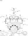
Figur 1 zeigt schematisch einen Teil einer Maschine gemäß einem Aspekt der Erfindung -
Figur 2
-
Figure 1 Figure 3 shows schematically part of a machine according to an aspect of the invention -
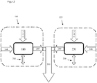
Figure 2 shows a scheme for balancing according to an aspect of the invention
Nachfolgend werden die Figuren detaillierter beschrieben.The figures are described in more detail below.
Zur Verbesserung der Trocknung der Faserstoffbahn wird über die Trockenhaube 12 heißes Gas, üblicherweise heiße Luft auf die Oberseite der Faserstoffbahn gebracht. Dazu ist in der Anlage von
Würde man die Luft ausschließlich in dem Kreislauf 180, 220 Haubenteil - Gebläse - Brenner -Haubenteil führen, wäre die Aufnahmefähigkeit dieser Luft für weitere Feuchtigkeit aus der Faserstoffbahn sehr schnell erreicht. Aus diesem Grund wird im Betrieb in Teil der (feuchten) Luft 260, 280 aus diesem Kreislauf 180, 220 über ein Abluftstellelement 26, 28, üblicherweise eine Abluftklappe 26, 28 entnommen. Zum Ausgleich wird dem jeweiligen Kreislauf 180, 220 über ein Zuluftstellelement 20, 24 (trockene) Zuluft 200, 240, meist Umgebungsluft zugeführt. Da die Temperatur der Umgebungsluft deutlich unter der Temperatur der Haubenluft liegt, ist es häufig zweckmäßig, die Zuluft vorher aufzuwärmen. In
Die in
Gemäß einem Aspekt der Erfindung können die Zuluftstellelemente 20, 24 - in der Regel Zuluftklappen 20, 24- automatisch angesteuert, das heißt geöffnet und geschlossen werden.
Eine Herausforderung beim Betrieb einer Maschine wie der in
Ein weiteres, wesentliches Element für den energieoptimierten Betrieb einer solchen Anlage ist die Steuerung bzw. Regelung der Menge der feuchten Luft, die über die gemeinsame Ableitung 30 aus der Haube 12 abgeführt wird.
Bei einer vorteilhaften Ausführung wird ein Zielwert oder ein Zielkorridor für diese Feuchte vorgegeben. Dieser Zielwert kann anlagenspezifisch festgelegt werden und gibt eine in gewissem Sinne optimale Abluftfeuchte an. Ein typischer Wert liegt üblicherweise über 500 g/kg, insbesondere über 600 g/kg. Um zu häufige Regeleingriffe zu vermeiden, kann auch ein Zielkorridor, z.B. 610 - 630 g/kg für die Feuchte vorgegeben werden.
To improve the drying of the fibrous web, hot gas, usually hot air, is brought to the top of the fibrous web via the drying
If the air were to be routed exclusively in the
In the
According to one aspect of the invention, the supply
A challenge when operating a machine like the one in
Another essential element for the energy-optimized operation of such a system is the control or regulation of the amount of moist air that is discharged from the
In an advantageous embodiment, a target value or a target corridor is specified for this humidity. This target value can be set system-specifically and indicates an optimal exhaust air humidity in a certain sense. A typical value is usually above 500 g / kg, in particular above 600 g / kg. In order to avoid control interventions that are too frequent, a target corridor, for example 610 - 630 g / kg, can be specified for the humidity.
Wenn hier über Eigenschaften der gemeinsamen Abluft 300 gesprochen wird, dann sind- wenn nicht anders erwähnt - diese Eigenschaften an einer frühen Stelle der gemeinsamen Ableitung 30 gemeint. Insbesondere an einer Stelle, an der die Ablufttemperatur noch relativ hoch ist, beispielsweise über 300°C oder gar über 400°C. Dies ist meist nach dem Luft-Luft Wärmetauscher 50 noch der Fall. Die oben angegebenen Feuchtewerte entsprechen dabei einer sehr geringen relativen Feuchte; einen messbare Kondensation hat hier noch nicht stattgefunden.
Für die Steuerung oder Regelung kann die Feuchte der gemeinsamen Abluft 300 in der gemeinsamen Ableitung 30 ermittelt werden, vorteilhafterweise direkt durch einen in der gemeinsamen Ableitung 30 installierten Feuchtesensor 61. Weiterhin kann ein Gebläse 60 installiert sein, mit dem der Volumenstrom der Abluft 300 in der gemeinsamen Ableitung 30 verändert werden kann. In
Eine Regelung wie die oben beschriebene ist aus energetischer Sicht zwar wünschenswert, führt aber zu der Schwierigkeit, dass dem System der Trockenhaube 12 zeitlich signifikant schwankende Mengen an Luft entzogen werden, die in geeigneter Weise von außen wieder zugeführt werden müssen. Zu diesem Zweck sind in
For the control or regulation, the humidity of the
A regulation like the one described above is desirable from an energetic point of view, but leads to the difficulty that amounts of air that fluctuate significantly over time are withdrawn from the system of the drying
Gemäß einem Aspekt der Erfindung kann das Zuluftstellelement 20 des Nassteils 18 und/oder das Zuluftstellelement 24 des Trockenteils 22 so geöffnet oder geschlossen werden, dass den Luftkreisläufen 180, 220 dieselbe Menge an Luft wieder zugeführt wird, die über die gemeinsame Ableitung 30 abgeführt wird. Um dies zu erreichen wird zumindest eine Massenbilanz erstellt, bevorzugt wird aber für jeden Haubenteil 18, 22 eine eigene Massenbilanz erstellt. Dabei wird bilanziert, welche Masse an trockener Luft dem Bilanzraum 185, 225 entzogen wird, und welche Masse an trockener Luft dem Bilanzraum 185, 225 zugeführt wird. Sind diese Massen nicht gleich, so kann über eine Verstellung der Zuluftstellelemente 20, 24 die Menge an Zuluft 200, 240 in jeden Haubenteil 18, 22 solange angepasst werden, bis die Bilanz im Gleichgewicht ist.
Die Masse an zugeführter und/oder abgeführter trockener Luft wird meist nicht direkt gemessen, sondern kann aus gemessenen oder ermittelten Werten von Volumenstrom, Feuchte, Temperatur und gegebenenfalls weiterer Parameter errechnet werden
Dazu kann die Maschine mit geeigneten Sensoren ausgestattet werden. Die in
Die Maschine in
The mass of supplied and / or discharged dry air is usually not measured directly, but can be calculated from measured or determined values of volume flow, humidity, temperature and possibly other parameters
The machine can be equipped with suitable sensors for this purpose. In the
The machine in
An dieser Stelle sei angemerkt, dass -verglichen mit der Abluft 260, 280, 300- die Feuchte der Umgebungsluft, die als Zuluft 200, 240 oder Verbrennungsluft 144,146 verwendet wird, sehr gering ist. Daher ist es möglich, auf die Messung der Feuchte in diesen Luftströmen zu verzichten, und stattdessen einen festen, geringen Wert anzusetzen. Insbesondere kann diese Luft auch als 'trockene Luft' angenommen werden. Der daraus entstehende Fehler in der Massenbilanz ist marginal und gerechtfertigt durch die Ersparnis durch den Verzicht auf Einbau und Wartung zusätzlicher Feuchtesensoren 61.At this point it should be noted that - compared with the
Eine etwas besondere Situation ist die Messung des Volumenstroms 260, 280 der Abluft 260, 280 aus Nassteil 18 und Trockenteil 22 durch die Abluftstellelemente 26, 28. Hier ist in vielen Anlagen der Bauraum ebenso wie die Länge der Rohrleitung bis zur gemeinsamen Ableitung 30 begrenzt. Üblicherweise muss sich vor der Messung eines Volumenstromes eine Strömung zuerst beruhigen, damit eine zuverlässige Messung erfolgen kann. Als Faustregel wird dazu eine Leitungslänge vom vierfachen des Leitungsquerschnitts benötigt. Bei üblichen Durchmessern für Leitungen der Abluft 260, 280, 300 von etwa 1m führt dies zu einer Leitungslänge von rund 4m. Dies ist baulich meist nicht, oder nur zu hohen Kosten möglich. Es hat sich gezeigt, dass insbesondere an diesen Stellen die Verwendung von Pöttersonden 64 zur Messung des Volumenstroms sehr vorteilhaft, da sie mit wesentlich kürzeren Leitungslängen verlässliche Ergebnisse liefern.
Unabhängig von den baulichen Gegebenheiten bietet an dieser Stelle die Messung mit Pöttersonden noch weitere Vorteile. Pöttersonden sind nämlich für die Durchflussmessung von Flüssigkeiten, Gasen und Dämpfen ebenso geeignet wie für wasserdampfgesättigte und/oder -verschmutzte Medien. Letzteres trifft auf die Abluft 260, 280 in besonderem Maße zu. Neben der Feuchte gerät nämlich bei der Trocknung der Faserstoffahn auch eine signifikante Menge an Partikeln wie Faserfragmenten oder mineralischen Füllstoffen in die Abluft 260, 280, was bei den üblichen Messgeräten zu Problemen führt. Die Messung mit Pöttersonden ist jedoch an diese Stelle ohne Schwierigkeiten möglich.A somewhat special situation is the measurement of the
Regardless of the structural conditions, measuring with Poetter probes offers further advantages at this point. Poetter probes are just as suitable for measuring the flow of liquids, gases and vapors as they are for media saturated and / or contaminated with water vapor. The latter applies particularly to the
Die in
Eine Steuerung bzw. Regelung wie beschrieben ermöglicht es nun, die Menge an Abluft aus energetischer Sicht optimal zu gestalten, und gleichzeitig immer die benötigte Menge an Zuluft zur Haube 12 bzw. den Haubenteilen 18, 22 zuzuführen.In the
A control or regulation as described now makes it possible to optimally design the amount of exhaust air from an energetic point of view and at the same time always supply the required amount of supply air to the
Eine Verbesserung der Steuerung bzw. der Regelung kann z.B. durch eine Verbesserung der Massenbilanzen erreicht werden. Häufig ist in zumindest einem, insbesondere in beiden Luftkreisläufen 180, 220 ein Brenner 44, 46 zum Aufheizen der Prozessluft vorgesehen ist, wobei der jeweilige Brenner 44, 46 mit Verbrennungsluft 144, 146 zum Unterhalten der Flamme versorgt wird. Da die Abgase der Verbrennung meist mit in den Luftkreislauf 180, 220 abgeführt werden, kann es vorteilhaft sein, wenn diese Verbrennungsluft 144, 146 in die Massenbilanz einbezogen wird.An improvement in the control or regulation can be achieved, for example, by improving the mass balances. A
Weiterhin sind die beiden Haubenteile 18, 22 auch nicht hermetisch geschlossen. So entsteht meist wischen dem Nassteil 18 sowie dem Trockenteil 22 der Trockenhaube 12 und dem Trockenzylinder 14 jeweils an einer Führerseite und einer Triebseite jeweils ein Spalt. Je nach Druckverhältnissen im Inneren des Haubenteils kann durch die Spalte Luft aus dem Haubenteil entweichen oder aber zuströmen. Diese Luftmengen sind vergleichsweise sehr gering, und können gegebenenfalls bei der Massenbilanz außer Acht gelassen werden. Durch eine Hinzunahme auch dieser Luftströmungen in den Bilanzraum 185, 225 kann die Massenbilanz jedoch weiter verbessert werden.
Da diese Strömungen eine Art Leckage Strömungen darstellen, ist ihre direkte Messung schwierig. Zudem ist die Strömung über die Länge eines Spaltes - in Umfangsrichtung des Zylinders betrachtet - nicht gleich. So erfolgt z.B. im Nassteil am Anfang des Spaltes tendenziell eher ein Einströmen von Luft in das Hauben innere, während am hinteren Ende ein Ausströmen erfolgt.Furthermore, the two
Since these currents represent a kind of leakage currents, it is difficult to measure them directly. In addition, the flow over the length of a gap - viewed in the circumferential direction of the cylinder - is not the same. For example, in the wet section at the beginning of the gap, air tends to flow into the inside of the hood, while at the rear end there is an outflow.
Eine Möglichkeit ist es, die Größe und/oder Richtung der Leckageströmung über die Messung der Spalttemperatur abzuschätzen, und mit in die Massenbilanz einzubeziehen.
So kann beispielsweise entlang eines Spalte eine Vielzahl, z.B. 4 oder mehr von Temperatursensoren 70 angeordnet sein, um die Spalttemperatur zu messen. Da die Haubenluft im Inneren der Haube mit 400°C und mehr deutlich heißer ist, als die Hallenluft mit ca. 25° gibt die Temperaturmessung einen Hinweis auf die Richtung der Leckageströmung. Misst der Sensor 70 eine sehr hohe Temperatur (z.B. >250°), so muss an dieser Stelle heiße Luft aus der Haube nach draußen strömen. Misst der Sensor sehr niedrige Temperaturen (z.B. < 100°C), so strömt an dieser Stelle kalte Hallenluft in die Haube 12, 18 ,22. In einem optimalen Betriebszustand werden einige Sensoren (z.B. die ersten beiden) niedrige Temperaturen anzeigen (=einströmende Luft), und die anderen hohe Temperaturen (ausströmende Luft). Dazwischen, also z.B. zwischen dem zweiten und dritten Sensor, erfolgt das Umschlagen von Einströmen und Ausströmen. Wandert der Umschlagpunkt nach vorne, strömt tendenziell mehr Luft durch den Spalt aus. Wandert der Umschlagpunkt nach hinten, tritt mehr Hallenluft in die Haube ein.
Eine Möglichkeit, die Leckageströme in die Massenbilanz einzubeziehen ist es, empirische Werte zu hinterlegen, und damit abhängig vom gemessenen Temperaturprofil oder von der Position des Umschlagpunkts einen Korrekturterm in die Massenbilanz aufzunehmen.
Diese Möglichkeit ist auch deshalb vorteilhaft, da häufig geeignete Temperatursensoren 70 bereits in bestehenden Hauben verbaut sindOne possibility is to estimate the size and / or direction of the leakage flow by measuring the gap temperature and to include it in the mass balance.
For example, a plurality, for example 4 or more, of
One possibility of including the leakage flows in the mass balance is to store empirical values and thus to include a correction term in the mass balance depending on the measured temperature profile or the position of the transition point.
This possibility is also advantageous because
Weiterhin ist in beiden Bilanzräumen 185, 225 auch noch die jeweilige Spaltströmung 210, 230 angeführt. Eine einfache Messung dieser Luftströme ist nicht möglich. Da die Strömungen verglichen mit den übrigen Strömen sehr klein sind (unter 5% der gesamten Ab- bzw. Zuluft) können sie gegebenenfalls bei der Massenbilanz außer Acht gelassen werden. Alternativ können sie auf Basis von Temperaturmessungen in den Spalten kombiniert mit empirischen Werten geschätzt und in die Massenbilanz mit aufgenommen werden.
Die Abluft 260 des Nassteils 18, sowie die Abluft 280 des Trockenteils 220 werden zusammengeführt und als gemeinsame Abluft 300 über die gemeinsame Ableitung 30 abgeführt. Wie bereits beschrieben ist es energetisch vorteilhaft, den Volumenstrom der gemeinsamen Abluft 300 so einzustellen, dass die Feuchte dieser gemeinsamen Abluft 300 in einem Zielintervall verbleibt- beispielsweise eine spezifische Feuchte zwischen 610 und 630 g/kg. Fällt die Feuchte der Abluft 300 darunter, kann weniger Abluft 300 abgeführt werden; ist die Feuchte oberhalb des Intervalls, kann die Abluftmenge 300 erhöht werden. Die somit vorgegebene Mengenänderung der gemeinsamen Abluft 300 verursacht eine Änderung sowohl der Abluft des Nassteils 260, als auch des Trockenteils 280.
Eine vorteilhafte Regelung kann nun dazu eingerichtet sein, sowohl für den Bilanzraum des Nassteils 185, als auch des Trockenteils 225 jeweils eine eigene Massenbilanz zu erstellen, und so zu regeln, dass dem Luftkreislauf 180 des Nassteils 18 wieder die Menge an trockener Luft zugeführt wird, die ihm über die Abluft 260 entzogen wird und ebenso dem Luftkreislauf 220 des Trockenteils 22 wieder die Menge an trockener Luft zugeführt wird, die ihm über die Abluft 280 entzogen wird.
Dabei ist eine Veränderung der Menge an Verbrennungsluft 144, 146 zur Einhaltung der Massenbilanz weniger gut geeignet, da diese Menge auf einen optimalen Betrieb der Brenner 44, 46 gewählt ist, und üblicherweise mittels einer separaten Brennerregelung eingestellt wird. Vorteilhafter ist es daher, wenn durch eine Regelung jeweils die Menge an Zuluft 200, 240, die über das Zuluftstellelement 20, 24 zugeführt wird, anzupassen.
Furthermore, the
The
An advantageous control can now be set up to create a separate mass balance for both the balance space of the
A change in the amount of
- 1212th
- TrockenhaubeDryer hood
- 1414th
- YankeezylinderYankee cylinder
- 1818th
- NassteilWet part
- 2020th
- Zuluftklappe (Nassteil)Supply air flap (wet end)
- 2222nd
- TrockenteilDry part
- 2424
- Zuluftklappe (Trockenteil)Supply air flap (dry part)
- 2626th
- Abluftklappe (Nassteil)Exhaust air flap (wet end)
- 2828
- Abluftklappe (Trockenteil)Exhaust air flap (dry part)
- 3030th
- gemeinsame Ableitungcommon derivation
- 3636
- Gebläse (Nassteil)Blower (wet end)
- 3838
- Gebläse (Trockenteil)Blower (dry part)
- 4444
- Brenner (Nassteil)Burner (wet end)
- 4646
- Brenner (Trockenteil)Burner (dry part)
- 5050
- WärmetauscherHeat exchanger
- 6060
- Gebläsefan
- 6161
- FeuchtesensorHumidity sensor
- 6262
- TemperatursensorTemperature sensor
- 6464
- Sensor VolumenstromVolume flow sensor
- 7070
- TemperatursensorTemperature sensor
- 144144
- Verbrennungsluft (Nassteil)Combustion air (wet part)
- 146146
- Verbrennungsluft (Trockenteil)Combustion air (dry part)
- 180180
- Luftkreislauf (Nassteil)Air circuit (wet part)
- 185185
- Bilanzraum (Nassteil)Balance area (wet section)
- 200200
- Zuluft (Nassteil)210 Spaltströmung (Nassteil)Supply air (wet section) 210 Gap flow (wet section)
- 220220
- Luftkreislauf (Trockenteil)Air circuit (dry part)
- 225225
- Bilanzraum (Trockenteil)Balance area (dry part)
- 230230
- Spaltströmung (Trockenteil)Gap flow (dry part)
- 240240
- Zuluft (Trockenteil)Supply air (dry part)
- 260260
- Abluft (Nassteil)Exhaust air (wet part)
- 280280
- Abluft (Trockenteil)Exhaust air (dry part)
- 300300
- gemeinsame Abluftcommon exhaust air
Claims (13)
dadurch gekennzeichnet, dass
eine Massenbilanz der zu- und abgeführten Luft erstellt wird, und den Luftkreisläufen (180, 220) dieselbe Menge an trockener Luft wieder zugeführt wird, die über die gemeinsame Ableitung (30) abgeführt wird.Method for controlling and / or regulating a process air system of a drying hood (12) associated with a drying cylinder (14), in particular a MG Yankee cylinder and / or Yankee cylinder, of a machine for producing a fibrous web, in particular a paper, cardboard or tissue web which a wet part (18) and a dry part (22) of the drying hood (12) are supplied with hot air via a respective air circuit (180, 220) and each air circuit (180, 220) via a respective supply air adjusting element (20 or 24) Duct system supply air is supplied and moist exhaust air is discharged via a respective exhaust air control element (26 or 28), and the moist exhaust air of the wet section (18) and the dry section (22) are discharged as common exhaust air (300) via a common discharge line (30) ,
characterized in that
a mass balance of the air supplied and discharged is created, and the same amount of dry air that is discharged via the common discharge line (30) is fed back to the air circuits (180, 220).
Applications Claiming Priority (1)
| Application Number | Priority Date | Filing Date | Title |
|---|---|---|---|
| DE102019125408.6A DE102019125408A1 (en) | 2019-09-20 | 2019-09-20 | Control and / or regulation of a process air system |
Publications (1)
| Publication Number | Publication Date |
|---|---|
| EP3795743A1 true EP3795743A1 (en) | 2021-03-24 |
Family
ID=71950508
Family Applications (1)
| Application Number | Title | Priority Date | Filing Date |
|---|---|---|---|
| EP20189604.0A Pending EP3795743A1 (en) | 2019-09-20 | 2020-08-05 | Method of controlling and/or regulating a process air system of a drying hood of a drying cylinder of a machine for making a fibrous web and machine for making a fibrous web |
Country Status (2)
| Country | Link |
|---|---|
| EP (1) | EP3795743A1 (en) |
| DE (1) | DE102019125408A1 (en) |
Cited By (2)
| Publication number | Priority date | Publication date | Assignee | Title |
|---|---|---|---|---|
| IT202100019160A1 (en) * | 2021-07-20 | 2023-01-20 | Toscotec S P A | Paper production plant. |
| IT202200005126A1 (en) * | 2022-03-16 | 2023-09-16 | Andritz Novimpianti S R L | SYSTEM AND METHOD FOR THE CONTROL OF PROCESS FLUIDS IN A PLANT FOR THE PRODUCTION OF RIBBON-SHAPED PAPER MATERIAL |
Citations (3)
| Publication number | Priority date | Publication date | Assignee | Title |
|---|---|---|---|---|
| EP3078772A2 (en) * | 2015-04-08 | 2016-10-12 | Voith Patent GmbH | Process air system |
| SE1750085A1 (en) * | 2017-02-02 | 2018-08-03 | Valmet Oy | A machine for making a tissue paper web and a method of operating such a machine |
| DE102017127664A1 (en) * | 2017-11-23 | 2019-05-23 | Voith Patent Gmbh | PROCESS AIR SYSTEM |
-
2019
- 2019-09-20 DE DE102019125408.6A patent/DE102019125408A1/en not_active Ceased
-
2020
- 2020-08-05 EP EP20189604.0A patent/EP3795743A1/en active Pending
Patent Citations (3)
| Publication number | Priority date | Publication date | Assignee | Title |
|---|---|---|---|---|
| EP3078772A2 (en) * | 2015-04-08 | 2016-10-12 | Voith Patent GmbH | Process air system |
| SE1750085A1 (en) * | 2017-02-02 | 2018-08-03 | Valmet Oy | A machine for making a tissue paper web and a method of operating such a machine |
| DE102017127664A1 (en) * | 2017-11-23 | 2019-05-23 | Voith Patent Gmbh | PROCESS AIR SYSTEM |
Non-Patent Citations (1)
| Title |
|---|
| SCHUKOV V ET AL: "YANKEE HOOD PERFORMANCE STUDIES: THE EFFECT OF AIR BALANCE ON THERMAL EFFICIENCY", TAPPI JOURNAL, TECHNICAL ASSOCIATION OF THE PULP & PAPER INDUSTRY. ATLANTA, US, vol. 74, no. 4, 1 April 1991 (1991-04-01), pages 141 - 145, XP000205066, ISSN: 0734-1415 * |
Cited By (3)
| Publication number | Priority date | Publication date | Assignee | Title |
|---|---|---|---|---|
| IT202100019160A1 (en) * | 2021-07-20 | 2023-01-20 | Toscotec S P A | Paper production plant. |
| IT202200005126A1 (en) * | 2022-03-16 | 2023-09-16 | Andritz Novimpianti S R L | SYSTEM AND METHOD FOR THE CONTROL OF PROCESS FLUIDS IN A PLANT FOR THE PRODUCTION OF RIBBON-SHAPED PAPER MATERIAL |
| EP4245911A1 (en) | 2022-03-16 | 2023-09-20 | ANDRITZ Novimpianti S.r.l. | System and method for controlling process fluids in a plant for manufacturing web-like paper material |
Also Published As
| Publication number | Publication date |
|---|---|
| DE102019125408A1 (en) | 2021-03-25 |
Similar Documents
| Publication | Publication Date | Title |
|---|---|---|
| DE69915701T2 (en) | METHOD AND DEVICE FOR REGULATING THE FIRST PART OF THE DRY PARTY OF A PAPER MACHINE | |
| EP2516949B1 (en) | Method and device for drying sheets of drywall | |
| DE4301023C2 (en) | Method and device for increasing the gloss and / or smoothness of a paper web | |
| AT411275B (en) | METHOD AND DEVICE FOR DRYING A RAIL SUPPORTED BY A SUPPORT FELT | |
| EP3795743A1 (en) | Method of controlling and/or regulating a process air system of a drying hood of a drying cylinder of a machine for making a fibrous web and machine for making a fibrous web | |
| DE2721965A1 (en) | METHOD AND DEVICE FOR MONITORING AND CONTROLLING THE DRYING PROCESS WHEN DRYING VENEERS AND SIMILAR GOODS | |
| DE60116563T3 (en) | METHOD AND DEVICE FOR DRYING A PULLEY CARRIER WITH HOT AIR OF DIFFERENT TEMPERATURE | |
| DE4325915A1 (en) | Method for measuring humidity of a material web on a continuous drier and device for carrying out the method | |
| EP3309294B1 (en) | Process air system | |
| EP0065783A1 (en) | Device for drying printed webs in a printing machine | |
| EP0967324B1 (en) | Process for smoothing a paper web | |
| EP0957202B1 (en) | Process and apparatus for making SC-A-paper online | |
| DE69914920T2 (en) | METHOD AND DEVICE FOR DRYING A COATED RAIL | |
| DE3224744A1 (en) | METHOD AND DEVICE FOR CONTROLLING THE EXHAUST HUMIDITY IN A DRYING SYSTEM | |
| EP2295632B1 (en) | Calendar | |
| DE60214380T3 (en) | METHOD AND DEVICE FOR CONTROLLING DRYING IN THE FIBER DRYER | |
| EP3244150A1 (en) | Dryer for web of textile fabric with a device for operation using minimal energy and method for same | |
| DE102008030340B4 (en) | Determination of speed relations between drive groups of a paper machine | |
| EP1026318B1 (en) | Calender | |
| DE102019123270A1 (en) | Method, system and computer program product for monitoring and / or controlling conditions in the section of a fiber web or equipment machine | |
| DE102017127664A1 (en) | PROCESS AIR SYSTEM | |
| AT521578B1 (en) | PROCESS, SYSTEM AND COMPUTER PROGRAM PRODUCT FOR MONITORING AND / OR CONTROLLING CONDITIONS IN THE SUB-SECTION OF A FIBERWAY OR EQUIPMENT MACHINE | |
| DE2437372A1 (en) | METHOD AND DEVICE FOR DRYING IN PARTICULAR HYGROSCOPIC MATERIAL, SUCH AS E. WOOD | |
| AT509529B1 (en) | METHOD AND DEVICE FOR CONTROLLING THE DRYING OF A COATED OR SURFACE MELTED FIBER TRAIN | |
| DE102008023595A1 (en) | Dryer for drying cloth in laundry, has heating stage attached at distributor in steam-side over pipeline, where pipeline guiding steam is provided for heating and pressure compensation with steam distributor |
Legal Events
| Date | Code | Title | Description |
|---|---|---|---|
| PUAI | Public reference made under article 153(3) epc to a published international application that has entered the european phase |
Free format text: ORIGINAL CODE: 0009012 |
|
| STAA | Information on the status of an ep patent application or granted ep patent |
Free format text: STATUS: THE APPLICATION HAS BEEN PUBLISHED |
|
| AK | Designated contracting states |
Kind code of ref document: A1 Designated state(s): AL AT BE BG CH CY CZ DE DK EE ES FI FR GB GR HR HU IE IS IT LI LT LU LV MC MK MT NL NO PL PT RO RS SE SI SK SM TR |
|
| AX | Request for extension of the european patent |
Extension state: BA ME |
|
| STAA | Information on the status of an ep patent application or granted ep patent |
Free format text: STATUS: REQUEST FOR EXAMINATION WAS MADE |
|
| 17P | Request for examination filed |
Effective date: 20210924 |
|
| RBV | Designated contracting states (corrected) |
Designated state(s): AL AT BE BG CH CY CZ DE DK EE ES FI FR GB GR HR HU IE IS IT LI LT LU LV MC MK MT NL NO PL PT RO RS SE SI SK SM TR |