EP3795412B1 - Stromversorgungssystem - Google Patents
Stromversorgungssystem Download PDFInfo
- Publication number
- EP3795412B1 EP3795412B1 EP19802955.5A EP19802955A EP3795412B1 EP 3795412 B1 EP3795412 B1 EP 3795412B1 EP 19802955 A EP19802955 A EP 19802955A EP 3795412 B1 EP3795412 B1 EP 3795412B1
- Authority
- EP
- European Patent Office
- Prior art keywords
- batteries
- output
- power
- input
- battery
- Prior art date
- Legal status (The legal status is an assumption and is not a legal conclusion. Google has not performed a legal analysis and makes no representation as to the accuracy of the status listed.)
- Active
Links
Images


Classifications
-
- B—PERFORMING OPERATIONS; TRANSPORTING
- B60—VEHICLES IN GENERAL
- B60L—PROPULSION OF ELECTRICALLY-PROPELLED VEHICLES; SUPPLYING ELECTRIC POWER FOR AUXILIARY EQUIPMENT OF ELECTRICALLY-PROPELLED VEHICLES; ELECTRODYNAMIC BRAKE SYSTEMS FOR VEHICLES IN GENERAL; MAGNETIC SUSPENSION OR LEVITATION FOR VEHICLES; MONITORING OPERATING VARIABLES OF ELECTRICALLY-PROPELLED VEHICLES; ELECTRIC SAFETY DEVICES FOR ELECTRICALLY-PROPELLED VEHICLES
- B60L58/00—Methods or circuit arrangements for monitoring or controlling batteries or fuel cells, specially adapted for electric vehicles
- B60L58/10—Methods or circuit arrangements for monitoring or controlling batteries or fuel cells, specially adapted for electric vehicles for monitoring or controlling batteries
- B60L58/12—Methods or circuit arrangements for monitoring or controlling batteries or fuel cells, specially adapted for electric vehicles for monitoring or controlling batteries responding to state of charge [SoC]
-
- B—PERFORMING OPERATIONS; TRANSPORTING
- B60—VEHICLES IN GENERAL
- B60L—PROPULSION OF ELECTRICALLY-PROPELLED VEHICLES; SUPPLYING ELECTRIC POWER FOR AUXILIARY EQUIPMENT OF ELECTRICALLY-PROPELLED VEHICLES; ELECTRODYNAMIC BRAKE SYSTEMS FOR VEHICLES IN GENERAL; MAGNETIC SUSPENSION OR LEVITATION FOR VEHICLES; MONITORING OPERATING VARIABLES OF ELECTRICALLY-PROPELLED VEHICLES; ELECTRIC SAFETY DEVICES FOR ELECTRICALLY-PROPELLED VEHICLES
- B60L58/00—Methods or circuit arrangements for monitoring or controlling batteries or fuel cells, specially adapted for electric vehicles
- B60L58/10—Methods or circuit arrangements for monitoring or controlling batteries or fuel cells, specially adapted for electric vehicles for monitoring or controlling batteries
- B60L58/18—Methods or circuit arrangements for monitoring or controlling batteries or fuel cells, specially adapted for electric vehicles for monitoring or controlling batteries of two or more battery modules
- B60L58/22—Balancing the charge of battery modules
-
- B—PERFORMING OPERATIONS; TRANSPORTING
- B60—VEHICLES IN GENERAL
- B60L—PROPULSION OF ELECTRICALLY-PROPELLED VEHICLES; SUPPLYING ELECTRIC POWER FOR AUXILIARY EQUIPMENT OF ELECTRICALLY-PROPELLED VEHICLES; ELECTRODYNAMIC BRAKE SYSTEMS FOR VEHICLES IN GENERAL; MAGNETIC SUSPENSION OR LEVITATION FOR VEHICLES; MONITORING OPERATING VARIABLES OF ELECTRICALLY-PROPELLED VEHICLES; ELECTRIC SAFETY DEVICES FOR ELECTRICALLY-PROPELLED VEHICLES
- B60L7/00—Electrodynamic brake systems for vehicles in general
- B60L7/10—Dynamic electric regenerative braking
- B60L7/16—Dynamic electric regenerative braking for vehicles comprising converters between the power source and the motor
-
- Y—GENERAL TAGGING OF NEW TECHNOLOGICAL DEVELOPMENTS; GENERAL TAGGING OF CROSS-SECTIONAL TECHNOLOGIES SPANNING OVER SEVERAL SECTIONS OF THE IPC; TECHNICAL SUBJECTS COVERED BY FORMER USPC CROSS-REFERENCE ART COLLECTIONS [XRACs] AND DIGESTS
- Y02—TECHNOLOGIES OR APPLICATIONS FOR MITIGATION OR ADAPTATION AGAINST CLIMATE CHANGE
- Y02T—CLIMATE CHANGE MITIGATION TECHNOLOGIES RELATED TO TRANSPORTATION
- Y02T10/00—Road transport of goods or passengers
- Y02T10/60—Other road transportation technologies with climate change mitigation effect
- Y02T10/70—Energy storage systems for electromobility, e.g. batteries
Definitions
- the present invention relates to a power supply system that controls the input/output of power to/from a plurality of batteries, by controlling a plurality of input/output adjustment apparatuses that are electrically connected between the plurality of batteries and a load.
- Japanese Laid-Open Patent Publication No. 2017-099242 discloses a power supply system using two different types of batteries, which are an output-type battery and a capacitance-type battery, the power supply system maintaining the output of the batteries during motoring and maintains reception of power by the batteries during regeneration, by controlling the SOC (State Of Charge) of the output-type battery.
- SOC State Of Charge
- Japanese Laid-Open Patent Publication No. 2015-220772 discloses a power supply system that includes a first power accumulator (main battery) that is high-output and high-cost and a plurality of second power accumulators (sub batteries) that have relatively low internal resistance values and are low-cost, with the sub batteries being attachable to and detachable from the power supply system.
- a first power accumulator main battery
- sub batteries second power accumulators
- US 2017/151886 A1 shows a power supply system comprising: a plurality of batteries; a plurality of input/output adjustment apparatuses that are electrically connected between the plurality of batteries and a load; and a control apparatus that controls input/output of power to/from the plurality of batteries by controlling the plurality of input/output adjustment apparatuses, wherein: during motoring in which power is output from the plurality of batteries to the load via the plurality of input/output adjustment apparatuses, the control apparatus controls the plurality of input/output adjustment apparatuses to output the power with priority from a battery whose SOC exceeds a threshold value among the plurality of batteries; and during regeneration in which power is input from the load to the plurality of batteries via the plurality of input/output adjustment apparatuses, the control apparatus controls the plurality of input/output adjustment apparatuses to input the power with priority to a battery whose SOC is less than or equal to the threshold value.
- Japanese Laid-Open Patent Publication No. 2017-099242 discloses a method for controlling the SOC among two types of batteries having different characteristics for the output-type batteries and the capacitance-type batteries, but does not disclose any method for controlling the SOC among a plurality of batteries that are the same type.
- the present invention has been devised in order to solve this type of problem, and has the object of providing, a power supply system capable of suitably controlling the SOC among a plurality of batteries.
- the present invention provides a power supply system according to claim 1.
- output from batteries with low SOCs is restricted during motoring, and power is input with priority to the batteries with low SOCs to recover the SOCs during regeneration. Therefore, it is possible to suppress variation in the SOC among the plurality of batteries, and to improve the output of the power supply system that includes the plurality of batteries.
- the SOCs are recovered without transferring power around, and therefore it is possible to suppress a drop in power efficiency.
- a power supply system 10 includes a plurality of first batteries 12, a plurality of DC/DC converters (input/output adjustment apparatuses) 14, a second battery 16, a power drive unit (PDU) 18, a battery ECU (control apparatus) 20, and a motor generator ECU (MG-ECU) 22.
- the power supply system 10 is used in an electric vehicle 24 such as a motorcycle, a three-wheel vehicle, or a four-wheel vehicle, for example.
- the plurality of first batteries 12 are attachable/detachable batteries that can be attached to and detached from the electric vehicle 24.
- each of the plurality of first batteries 12 is housed in a battery pack 28 that includes a battery management system (BMU) 26 that monitors the first batteries 12.
- BMU battery management system
- the plurality of first batteries 12 may be the same type of battery, or may be different types of batteries from each other.
- the number of first batteries 12 shown in FIG. 1 is just an example, and the power supply system 10 may include two or more first batteries 12.
- the plurality of BMUs 26 sequentially detect the battery voltage, battery current, and temperature of the first batteries 12, using sensors (not shown in the drawings). These states of the first batteries 12 are sequentially transmitted from the plurality of BMUs 26 to the battery ECU 20, via a communication line 30.
- the plurality of DC/DC converters 14 have first-order sides that are electrically connected to any one of the first batteries 12 among the plurality of first batteries 12, and second-order sides that are electrically connected to the PDU 18. Accordingly, the plurality of DC/DC converters 14 are connected in parallel to the PDU 18. By raising/lowering the battery voltages of the first batteries 12 connected on the first-order side, the plurality of DC/DC converters 14 adjust the voltage (output voltage) output to the PDU 18 to be a desired output voltage value and adjust the current (output current) flowing through the PDU 18 to be a desired output current value. Furthermore, the DC/DC converters 14 sequentially transmit their own states to the battery ECU 20, via the communication line 30.
- the second battery 16 is a fixed battery included in the electric vehicle 24.
- the battery voltage, battery current, and temperature of the second battery 16 are also detected by sensors (not shown in the drawings). These states of the second battery 16 are sequentially transmitted to the battery ECU 20, via the communication line 32. It should be noted that the second battery 16 is not a strictly necessary configurational element, as described further below.
- the PDU 18 is configured to include a three-phase bridge inverter.
- the plurality of DC/DC converters 14 and the second battery 16 are connected in parallel to the input side of the PDU 18.
- a motor 34 of the electric vehicle 24, which is the load of the power supply system 10, is electrically connected to the output side of the PDU 18.
- DC power is supplied from the plurality of first batteries 12 to the PDU 18 via the plurality of DC/DC converters 14 or from the second battery 16 to the PDU 18.
- the PDU 18 converts the DC power into three-phase AC power, and supplies this AC power to the motor 34. Due to this, the motor 34 can be driven and the electric vehicle 24 can be made to travel.
- the PDU 18 converts the AC power generated by the motor 34 into DC power. Due to this, the DC power can be input (charged) to the plurality of first batteries 12 via the plurality of DC/DC converters 14 or input (charged) to the second battery 16.
- the MG-ECU 22 is an ECU (Electronic Control Unit) for controlling the PDU 18 and the motor 34.
- the MG-ECU 22 is connected to the PDU 18 and the battery ECU 20 in a manner enabling the communication of signals or information, via communication lines 36 and 38. Furthermore, the MG-ECU 22 and the motor 34 are electrically connected via a communication line 40.
- the MG-ECU 22 supplies a control signal (signal indicating a torque command value) for operating a switching element forming the PDU 18, via the communication line 36.
- the PDU 18 transmits the state of the PDU 18 or a protection request for the MG-ECU 22, via the communication line 36.
- the motor 34 transmits the state of the motor 34 or a protection request for the MG-ECU 22, via the communication line 40.
- Manipulation amounts of an acceleration manipulating section, a throttle manipulating section, and the like manipulated by a driver of the electric vehicle 24 and the state of the electric vehicle 24 such as the vehicle velocity or a load request value of auxiliary equipment are input to the MG-ECU 22.
- the MG-ECU 22 calculates the requested output of the motor 34 based on the state of the electric vehicle 24 input thereto and the information transmitted from the PDU 18 and the motor 34, and transmits the calculated requested output to the battery ECU 20 via the communication line 38.
- the requested output of the motor 34 includes a request for a power amount (motoring-time requested output) necessary for driving of the motor 34, made by the motor 34 during motoring to each first battery 12 and the second battery 16, and a request for a regeneration power amount (regeneration-time requested output) from the motor 34 made by the motor 34 to each first battery 12 and the second battery 16 when the motor 34 generates power during regeneration.
- the MG-ECU 22 is capable of transmitting the state of the PDU 18 and the like to the battery ECU 20, via the communication line 38.
- the battery ECU 20 is an ECU for controlling the plurality of DC/DC converters 14.
- the battery ECU 20 performs various processes by reading and executing a program stored in a memory (not shown in the drawings). Specifically, the battery ECU 20 calculates the SOC of each first battery 12 and the second battery 16 from the received states of each of the plurality of first batteries 12 and the second battery 16. Furthermore, the battery ECU 20 calculates a power amount (motoring-time allowed power amount) capable of being output from each first battery 12 and the second battery 16 during motoring and a power amount (regeneration-time allowed power amount) capable of being input to each first battery 12 and the second battery 16 during regeneration. Yet further, the battery ECU 20 calculates a limit current value of each DC/DC converter 14, from the received states of the plurality of DC/DC converters 14.
- the battery ECU 20 calculates a total value (motoring-time total power amount) of the amount of power that can be output from all of the first batteries 12 and the second battery 16, based on each calculated SOC, each power amount allowed during motoring, each limit current value, the requested output (motoring-time requested output) of the motor 34 received from the MG-ECU 22, and the like.
- the battery ECU 20 then calculates a power amount (motoring-time power distribution amount) actually output from each first battery 12 and the second battery 16 by distributing the motoring-time total power amount based on the state of each first battery 12 and the second battery 16.
- the battery ECU 20 calculates a total value (regeneration-time total power amount) of the amount of power that can be input to all of the first batteries 12 and the second battery 16, based on each regeneration-time allowed power amount, each limit current value, the requested output (regeneration-time requested output) of the motor 34 received from the MG-ECU 22, and the like.
- the battery ECU 20 calculates a power amount (regeneration-time power distribution amount) actually input to each first battery 12 and the second battery 16 by distributing the regeneration-time total power amount based on the state of each first battery 12 and the second battery 16.
- the battery ECU 20 calculates a motoring-time target current value based on each calculated motoring-time power distribution amount or calculates a regeneration-time target current value based on each calculated regeneration-time power distribution amount. In this way, the battery ECU 20 transmits the target current values to the plurality of DC/DC converters 14 and transmits the battery information such as the SOC of each first battery 12 and the second battery 16 to the MG-ECU 22, via the communication line 30.
- the plurality of DC/DC converters 14 raise or lower the battery voltages of the connected first batteries 12 based on the received target current value, thereby adjusting the output voltage that is output to the second-order side (input side of the PDU 18) and adjusting the output current output to the second-order side to be the target current value.
- the MG-ECU 22 transmits a control signal based on the received information of each first battery 12 and the second battery 16 to the PDU 18, via the communication line 36.
- the PDU 18 causes a switching element to operate based on the received control signal.
- DC power corresponding to the motoring-time power distribution amount is output from each first battery 12 and the second battery 16, and the PDU 18 converts each output DC power into AC power and supplies this AC power to the motor 34.
- the motor 34 can be driven and the electric vehicle 24 can be made to travel.
- the motor 34 generates power and outputs AC power to the PDU 18, and the PDU 18 converts the AC power to DC power.
- the DC power resulting from the conversion is distributed according to each regeneration-time power distribution amount and input (charged) to each first battery 12 and the second battery 16.
- the second battery 16 is installed, but the following description concerns the power amount distribution to the plurality of first batteries 12. Accordingly, it should be noted that the second battery 16 is not a strictly essential configurational component in the power supply system 10.
- FIG. 2 is a conceptual diagram of the SOCs of the plurality of first batteries 12.
- a plurality of first batteries 12 are included in the power supply system 10 (four first batteries 12 in FIGS. 1 and 2 ), as shown in FIG. 2 , there are cases where the individual first batteries 12 have different SOCs from each other.
- the number of first batteries 12 is N
- the average value (threshold value, SOC average value) of the SOCs of the plurality of first batteries 12 is SOCave
- the number of first batteries 12 whose SOCs exceed the SOC average value SOCave is n
- the difference between the highest SOC and the lowest SOC among all of the first batteries 12 is ⁇ SOC.
- the number of first batteries 12 whose SOCs are less than or equal to the SOC average value SOCave is (N-n).
- the "n first batteries 12 whose SOCs exceed the SOC average value SOCave” may be referred to as the "n first batteries 12" and the "(N-n) first batteries 12 whose SOCs are less than or equal to the SOC average value SOCave” may be referred to as the "(N-n) first batteries 12".
- FIGS. 3 and 4 show the relationship between the burden rates and ⁇ SOC, with the horizontal axis indicating ⁇ SOC and the vertical axis indicating the burden rate of each first battery 12 during motoring and during regeneration.
- the burden rate indicates the ratio with which each first battery 12 bears the input/output of the power amount, with respect to the requested output (motoring-time requested output, regeneration-time requested output).
- the motoring-time total power amount for the motoring-time requested output is calculated, and the motoring-time burden rate indicates what ratio of the power amount is to be output (borne) by each first battery 12 for the motoring-time requested output (motoring-time total power amount).
- the regeneration-time total power amount for the regeneration-time requested output is calculated, and the regeneration-time burden rate indicates what ratio of the power amount is to be input (borne) by each first battery 12 for the regeneration-time requested output (regeneration-time total power amount).
- the burden rate during motoring is shown in the positive direction of the vertical axis and the burden rate during regeneration is shown in the negative direction of the vertical axis.
- the burden rates during motoring and during regeneration are described as absolute values. Accordingly, it should be noted that the greater the distance in the positive direction or negative direction from 0 [%] on the vertical axis, the larger the burden rate of each first battery 12 during motoring and during regeneration.
- the concept shown in FIGS. 3 and 4 is that, with the SOC average value SOCave serving as a threshold value, after dividing all of the first batteries 12 into a group of n first batteries 12 whose SOCs exceed the threshold value (SOC average value SOCave) and a group of (N-n) first batteries 12 whose SOCs are less than or equal to the threshold value, the burden rates of the first batteries 12 associated with the respective groups are changed between a case where ⁇ SOC is less than a prescribed value A ( ⁇ SOC ⁇ A) and a case where ⁇ SOC is greater than or equal to the prescribed value A ( ⁇ SOC ⁇ A). Furthermore, it should be noted that in FIGS. 3 and 4 , the burden rates of the first batteries 12 in the group of n first batteries 12 are the same value as each other, and the burden rates of the first batteries 12 in the group of (N-n) first batteries 12 are the same value as each other.
- FIG. 3 shows the distribution of the power amount in a case where it is possible, during motoring, to output a power amount corresponding to the motoring-time requested output from only the n first batteries 12 whose SOCs exceed SOCave and, during regeneration, to input a power amount corresponding to the regeneration-time requested output to only the (N-n) first batteries 12 whose SOCs are less than or equal to the SOC average value SOCave.
- the solid lines indicate the change of the burden rate for the n first batteries 12 and the dashed lines indicate the change of the burden rate for the (N-n) first batteries 12.
- the battery ECU 20 sets the burden rate of each first battery 12 for the motoring-time requested output (motoring-time total power amount) to be 100/N [%]. Due to this, all of the first batteries 12 equally bear the motoring-time requested output, and output the same power amount.
- the battery ECU 20 sets the burden rate of each first battery 12 for the motoring-time requested output (motoring-time total power amount) to be 100/n [%] for the n first batteries 12, as shown by the solid line, and to be 0[%] for the (N-n) first batteries 12, as shown by the dashed line. In this way, a power amount corresponding to a burden rate of 100/n [%] is output with priority only from the n first batteries 12.
- the battery ECU 20 sets the burden rate of each first battery 12 for the regeneration-time requested output (regeneration-time total power amount) to be 100/N [%]. Due to this, all of the first batteries 12 equally bear the regeneration-time requested output, and receive (are charged with) the same power amount.
- the battery ECU 20 sets the burden rate of each first battery 12 for the regeneration-time requested output (regeneration-time total power amount) to be 0 [%] for the n first batteries 12, as shown by the solid line, and to be 100/(N-n) [%] for the (N-n) first batteries 12, as shown by the dashed line. In this way, a power amount corresponding to a burden rate of 100/(N-n) [%] is input (charged) with priority to only the (N-n) first batteries 12.
- the battery ECU 20 changes the burden rates using the prescribed value A [%] as a boundary.
- the battery ECU 20 may gradually change the burden rates for the n first batteries 12 and the (N-n) first batteries 12 within a range of ⁇ A [%] that is from A0 [%] to A [%].
- FIG. 3 a case where the burden rates are changed at the prescribed value A [%] is shown by a single-dot chain line.
- FIG. 4 shows the distribution of the power amount in a case where, during motoring, it is necessary to output power from the (N-n) first batteries 12 as well due to the n first batteries 12 alone being unable to output (cover) the power amount corresponding to the motoring-time requested output and where, during regeneration, an excess portion (residual portion) of the power amount occurs when power has been input to only the (N-n) first batteries 12, due to the regeneration-time requested output being large.
- the battery ECU 20 sets the burden rate of each first battery 12 for the motoring-time requested output to be 100/N [%].
- the battery ECU 20 sets the burden rate for the motoring-time requested output to be B1 ⁇ n/Poreq [%] for the n first batteries 12, as shown by the solid line, and to be ⁇ o [%] for the (N-n) first batteries 12, as shown by the dashed line.
- B1 indicates the power amount (motoring-time allowed power amount) capable of being output during motoring by each of the n first batteries 12.
- Poreq is the motoring-time requested output.
- the insufficient portion of the power amount is output from the (N-n) first batteries 12 in addition to the power amount output from the n first batteries 12, and so it is possible to efficiently output power even when the motoring-time requested output is large.
- the battery ECU 20 sets the burden rate of each first battery 12 for the regeneration-time requested output to be 100/N [%].
- the battery ECU 20 sets the burden rate of each first battery 12 for the regeneration-time requested output to be ⁇ i [%] for the n first batteries 12, as shown by the solid line, and to be B2 ⁇ (N-n)/Pireq [%] for the (N-n) first batteries 12, as shown by the dashed line.
- B2 indicates the power amount (regeneration-time allowed power amount) capable of being input during regeneration to each of the (N-n) first batteries 12.
- Pireq is the regeneration-time requested output.
- FIGS. 1 to 4 will also be referenced as needed.
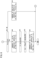
- the operation of the power supply system 10 for realizing the concepts of FIGS. 3 and 4 is described while referencing the flow charts of FIGS. 5 and 6 .
- the battery ECU 20 acquires the state (battery voltage, battery current, and temperature) of each first battery 12 from the BMUs 26 attached to the plurality of first batteries 12.
- the battery ECU 20 calculates the SOC of each first battery 12 based on the acquired state of each first battery 12. Furthermore, the battery ECU 20 calculates the SOC average value SOCave of each of the first batteries 12, and also calculates the difference ⁇ SOC between the highest SOC and the lowest SOC for each of the first batteries 12.
- the battery ECU 20 judges whether ⁇ SOC is greater than or equal to the prescribed value A [%].
- the battery ECU 20 calculates the target current value during motoring based on each calculated motoring-time power distribution amount Pbo.
- the battery ECU 20 transmits the target current value to the plurality of DC/DC converters 14, via the communication line 30.
- the plurality of DC/DC converters 14 can output a power amount corresponding to the motoring-time power distribution amount Pbo from the first batteries 12, by performing a voltage raising/lowering operation on the battery voltage based on the received target current value.
- the sum total of the power amount output to the PDU 18 from the plurality of first batteries 12 can be adjusted to be the motoring-time requested output Poreq (motoring-time total power amount).
- step S12 if ⁇ SOC is greater than or equal to the prescribed value A ( ⁇ SOC ⁇ A, step S12: YES), the process moves to step S14.
- the battery ECU 20 calculates the power amount B1 (motoring-time allowed power amount) capable of being output during motoring, for each of the n first batteries 12.
- the battery ECU 20 judges whether the motoring-time requested output Poreq is greater than or equal to the total value B1 ⁇ n of the power capable of being output from the n first batteries 12.
- step S15 if the motoring-time requested output Poreq is less than the total value B1 ⁇ n (Poreq ⁇ B1 ⁇ n, step S15: NO), the process moves to step S16.
- the battery ECU 20 then calculates the target current value during motoring, based on each calculated motoring-time power distribution amount Pbon.
- the battery ECU 20 transmits the target current value to the plurality of DC/DC converters 14, via the communication line 30. Due to this, the plurality of DC/DC converters 14 can output a power amount corresponding to the motoring-time power distribution amount Pbon from the first batteries 12, by performing the voltage raising/lowering operation on the battery voltage based on the received target current value. In this case as well, the total sum of the power amount output to the PDU 18 from the plurality of first batteries 12 can be adjusted to the motoring-time requested output Poreq (motoring-time total power amount).
- step S16 it should be noted that the motoring-time power distribution amount for the (N-n) first batteries 12 is 0, and that the target current value is also 0.
- step S15 if the motoring-time requested output Poreq is greater than or equal to the total value B1 ⁇ n (Poreq ⁇ B1 ⁇ n, step S15: YES), the process moves to step S17.
- the battery ECU 20 calculates the target current value at the time when the motoring-time power distribution amount Pbon is the power amount B1, for the DC/DC converters 14 connected to the n first batteries 12.
- the battery ECU 20 transmits this target current value to the DC/DC converters 14 connected to the n first batteries 12, via the communication line 30. Due to this, the DC/DC converters 14 that receive the target current value can output the power amount B1 from the n first batteries 12, by performing the voltage raising/lowering operation on the battery voltage based on this target current value.
- the battery ECU 20 transmits this target current value to the DC/DC converters 14 connected to the (N-n) first batteries 12, via the communication line 30. Due to this, the DC/DC converters 14 that receive the target current value can output the power amount C1/(N-n), which is the insufficient portion, from the (N-n) first batteries 12, by performing the voltage raising/lowering operation on the battery voltage based on this target current value.
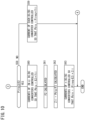
- the battery ECU 20 acquires the state of the first batteries 12 from the BMUs 26 and calculates the SOC of each first battery 12 based on the acquired state of each first battery 12, in the same manner as in step S11 of FIG. 5 . In this case as well, the battery ECU 20 calculates the SOC average value SOCave and the difference ⁇ SOC.
- step S22 the battery ECU 20 judges whether ⁇ SOC is greater than or equal to the prescribed value A [%], in the same manner as in step S12.
- the battery ECU 20 then calculates the target current value during regeneration based on each calculated regeneration-time power distribution amount Pbi.
- the battery ECU 20 transmits the target current value to the plurality of DC/DC converters 14, via the communication line 30.
- the plurality of DC/DC converters 14 can input a power amount corresponding to the regeneration-time power distribution amount Pbi to the first batteries 12, by performing the voltage raising/lowering operation on the battery voltage based on the received target current value.
- the sum total of the power amount input to the plurality of first batteries 12 is adjusted to be the regeneration-time requested output Pireq (regeneration-time total power amount).
- step S22 if ⁇ SOC is greater than or equal to the prescribed value A ( ⁇ SOC ⁇ A, step S22: YES), the process moves to step S24.
- the battery ECU 20 calculates the power amount B2 (regeneration-time allowed power amount) capable of being input during regeneration, for each of the (N-n) first batteries 12.
- the battery ECU 20 judges whether the regeneration-time requested output Pireq is greater than or equal to the total value B2 ⁇ (N-n) of the power capable of being input to the (N-n) first batteries 12.
- step S25 if the regeneration-time requested output Pireq is less than the total value B2 ⁇ (N-n) (Pireq ⁇ B2 ⁇ (N-n), step S25: NO), the process moves to step S26.
- the battery ECU 20 calculates the target current value during regeneration, based on each calculated regeneration-time power distribution amount Pbiu.
- the battery ECU 20 transmits the target current value to the plurality of DC/DC converters 14, via the communication line 30. Due to this, the plurality of DC/DC converters 14 can input a power amount corresponding to the regeneration-time power distribution amount Pbiu with priority to the (N-n) first batteries 12, by performing the voltage raising/lowering operation on the battery voltage based on the received target current value. In this case as well, the total sum of the power amount input to the plurality of first batteries 12 can be adjusted to the regeneration-time requested output Pireq (regeneration-time total power amount).
- the burden rate of the n first batteries 12 is 0 [%]. Therefore, at step S26, it should be noted that the regeneration-time power distribution amount for the n first batteries 12 is 0, and that the target current value is also 0.
- step S25 if the regeneration-time requested output Pireq is greater than or equal to the total value B2 ⁇ (N-n) (Pireq ⁇ B2 ⁇ (N-n), step S25: YES), the process moves to step S27.
- the battery ECU 20 calculates the target current value at the time when the regeneration-time power distribution amount Pbiu is the power amount B2, for the DC/DC converters 14 connected to the (N-n) first batteries 12.
- the battery ECU 20 transmits this target current value to the DC/DC converters 14 connected to the (N-n) first batteries 12, via the communication line 30. Due to this, the DC/DC converters 14 that receive the target current value can input the power amount B2 with priority to the (N-n) first batteries 12, by performing the voltage raising/lowering operation on the battery voltage based on this target current value.
- the battery ECU 20 transmits this target current value to the DC/DC converters 14 connected to the n first batteries 12, via the communication line 30. Due to this, the DC/DC converters 14 that receive the target current value can input the power amount C2/n to the n first batteries 12, by performing the voltage raising/lowering operation on the battery voltage based on this target current value.
- FIGS. 5 and 6 in order to reflect the concepts of FIGS. 3 and 4 , an example is described of a case in which input/output of the same power amounts is performed for the n first batteries 12 whose SOCs exceed the SOC average value SOCave, and input/output of the same power amounts is performed for the (N-n) first batteries 12 whose SOCs are less than or equal to the SOC average value SOCave.
- a case is described in which the n first batteries 12 have the same burden rates as each other and the (N-n) first batteries 12 have the same burden rates as each other.
- FIGS. 7 to 10 differ from FIGS. 5 and 6 in that the burden rates (output burden rates) of the individual first batteries 12 are different from each other. It should be noted that, in the modification of FIGS. 7 to 10 , there can be cases where the target current values transmitted from the battery ECU 20 to the plurality of DC/DC converters 14 differ for each DC/DC converter 14, according to the burden rate.
- the battery ECU 20 acquires the state of the first batteries 12 from the plurality of BMUs 26, and calculates the SOCs of the first batteries 12 based on the acquired states of the first batteries 12, in the same manner as in step S11 of FIG. 5 . Furthermore, the battery ECU 20 calculates the SOC average value SOCave and the difference ⁇ SOC.
- the battery ECU 20 judges whether ⁇ SOC is greater than or equal to the prescribed value A [%].
- step S33 the battery ECU 20 calculates a motoring-time total power amount D1, which is the total value of the power amount capable of being output from the plurality of first batteries 12 during motoring.
- the battery ECU 20 then calculates the target current value during motoring based on each calculated motoring-time power distribution amount Pbo.
- the battery ECU 20 transmits the target current value to the plurality of DC/DC converters 14, via the communication line 30. Due to this, the plurality of DC/DC converters 14 can output a power amount corresponding to the motoring-time power distribution amount Pbo from the first batteries 12, by performing the voltage raising/lowering operation on the battery voltage based on the received target current value.
- step S32 if ⁇ SOC is greater than or equal to the prescribed value A ( ⁇ SOC ⁇ A, step S32: YES), the process moves to step S36.
- the battery ECU 20 calculates a power amount E1 that is the total value of the power amount capable of being output from the n first batteries 12.
- the battery ECU 20 judges whether the motoring-time requested output Poreq is greater than or equal to the power amount E1.
- step S38 of FIG. 8 if the motoring-time requested output Poreq is less than the power amount E1 (Poreq ⁇ E1, step S38: NO), the process moves to step S39.
- the battery ECU 20 then calculates the target current value during motoring, based on each calculated motoring-time power distribution amount Pbon.
- the battery ECU 20 transmits the target current value to the plurality of DC/DC converters 14, via the communication line 30. Due to this, the plurality of DC/DC converters 14 can output a power amount corresponding to the motoring-time power distribution amount Pbon from the first batteries 12, by performing the voltage raising/lowering operation on the battery voltage based on the received target current value.
- step S38 if the motoring-time requested output Poreq is greater than or equal to the power amount E1 (Poreq ⁇ E1, step S38: YES), the process moves to step S40.
- the battery ECU 20 calculates the target current value corresponding to the motoring-time power distribution amount Pbon, for the DC/DC converters 14 connected to the n first batteries 12.
- the battery ECU 20 transmits this target current value to the DC/DC converters 14 connected to the n first batteries 12, via the communication line 30. Due to this, the DC/DC converters 14 that receive the target current value can output the motoring-time power distribution amount Pbon from the n first batteries 12, by performing the voltage raising/lowering operation on the battery voltage based on this target current value.
- the battery ECU 20 calculates F1, which is the total value of the power amount capable of being output from the (N-n) first batteries 12.
- the battery ECU 20 calculates a target current value corresponding to the motoring-time power distribution amount Pbou for the DC/DC converters 14 connected to the (N-n) first batteries 12.
- the battery ECU 20 transmits this target current value to the DC/DC converters 14 connected to the (N-n) first batteries 12, via the communication line 30. Due to this, the DC/DC converters 14 that receive the target current value can output the motoring-time power distribution amount Pbou from the (N-n) first batteries 12, by performing the voltage raising/lowering operation on the battery voltage based on this target current value.
- the battery ECU 20 acquires the states of the first batteries 12 from the BMUs 26 and calculates the SOCs of the first batteries 12 based on the acquired states of the first batteries 12, in the same manner as in step S21 of FIG. 6 . Furthermore, the battery ECU 20 calculates the SOC average value SOCave and the difference ⁇ SOC.
- the battery ECU 20 judges whether ⁇ SOC is greater than or equal to the prescribed value A [%].
- step S53 the battery ECU 20 calculates a regeneration-time total power amount D2, which is the total value of the power amount capable of being input to the plurality of first batteries 12 during regeneration.
- the battery ECU 20 transmits the target current value to the plurality of DC/DC converters 14, via the communication line 30. Due to this, the plurality of DC/DC converters 14 can input a power amount corresponding to the regeneration-time power distribution amount Pbi to the first batteries 12, by performing the voltage raising/lowering operation on the battery voltage based on the received target current value.
- step S52 if ⁇ SOC is greater than or equal to the prescribed value A ( ⁇ SOC ⁇ A, step S52: YES), the process moves to step S56.
- the battery ECU 20 calculates the power amount E2, which is the total value of the power amount capable of being input to the (N-n) first batteries 12.
- the battery ECU 20 judges whether the regeneration-time requested output Pireq is greater than or equal to the power amount E2.
- step S58 if the regeneration-time requested output Pireq is less than the power amount E2 (Pireq ⁇ E2, step S58: NO), the process moves to step S59.
- the battery ECU 20 then calculates the target current value during regeneration, based on each calculated regeneration-time power distribution amount Pbiu.
- the battery ECU 20 transmits the target current value to the plurality of DC/DC converters 14, via the communication line 30. Due to this, the plurality of DC/DC converters 14 can input a power amount corresponding to the regeneration-time power distribution amount Pbiu with priority to the (N-n) first batteries 12, by performing the voltage raising/lowering operation on the battery voltage based on the received target current value.
- step S58 if the regeneration-time requested output Pireq is greater than or equal to the power amount E2 (Pireq ⁇ E2, step S58: YES), the process moves to step S60.
- the battery ECU 20 calculates the target current value corresponding to the regeneration-time power distribution amount Pbiu, for the DC/DC converters 14 connected to the (N-n) first batteries 12.
- the battery ECU 20 transmits this target current value to the DC/DC converters 14 connected to the (N-n) first batteries 12, via the communication line 30. Due to this, the DC/DC converters 14 that receive the target current value can input the regeneration-time power distribution amount Pbiu with priority to the (N-n) first batteries 12, by performing the voltage raising/lowering operation on the battery voltage based on this target current value.
- the battery ECU 20 calculates F2, which is the total value of the power amount capable of being input to the n first batteries 12.
- the battery ECU 20 calculates a target current value corresponding to the regeneration-time power distribution amount Pbin for the DC/DC converters 14 connected to the n first batteries 12.
- the battery ECU 20 transmits this target current value to the DC/DC converters 14 connected to the n first batteries 12, via the communication line 30. Due to this, the DC/DC converters 14 that receive the target current value can input the regeneration-time power distribution amount Pbin to the n first batteries 12, by performing the voltage raising/lowering operation on the battery voltage based on this target current value.
- the power supply system 10 includes the plurality of first batteries 12, the plurality of DC/DC converters 14 (input/output adjustment apparatuses) that are electrically connected between the plurality of first batteries 12 and the motor 34 (load), and the battery ECU 20 (control apparatus) that controls the input/output of power to/from the plurality of first batteries 12 by controlling the plurality of DC/DC converters 14.
- the battery ECU 20 controls the plurality of DC/DC converters 14 to output the power with priority from the first batteries 12 whose SOCs exceed a threshold value (SOC average value SOCave) among the plurality of first batteries 12. Furthermore, during regeneration in which power is input from the motor 34 to the plurality of first batteries 12 via the plurality of DC/DC converters 14, the battery ECU 20 controls the plurality of DC/DC converters 14 to input power with priority to the first batteries 12 whose SOCs are less than or equal to the threshold value among the plurality of first batteries 12.
- the SOCs are recovered without transferring power around, and therefore it is possible to suppress a drop in the power efficiency.
- the threshold value is the SOC average value SOCave of the plurality of the first batteries 12 and, during motoring, the battery ECU 20 may control the plurality of DC/DC converters 14 to output the power with priority from the first batteries 12 (n first batteries 12) whose SOCs exceed the SOC average value SOCave. In this way, it is possible to uniformly utilize the SOC of each first battery 12. In other words, since power is output with priority from the n first batteries 12 having high SOCs, it is possible to output power while restricting variation in the SOC among the first batteries 12 with relatively simple control.
- the battery ECU 20 controls the plurality of DC/DC converters 14 to output power from these first batteries 12 to the motor 34 via the DC/DC converters 14. In this way, it is possible to more efficiently utilize the SOC of each first battery 12.
- the battery ECU 20 controls the plurality of DC/DC converters 14 to output just this power amount from these first batteries 12 to the motor 34 via the DC/DC converters 14, and to output a power amount equal to the insufficient amount relative to the requested output to the motor 34 from the first batteries 12 ((N-n) first batteries 12) whose SOCs are less than or equal to the SOC average value SOCave, via the DC/DC converters 14 connected to these first batteries 12. In this way, even when the requested output is large, it is possible to efficiently utilize the SOC of each first battery 12.
- the battery ECU 20 controls the plurality of DC/DC converters 14 to output the same power amount from the plurality of first batteries 12 or to output power amounts corresponding to the output burden rates of the plurality of first batteries 12 for the requested output. In this way, it is possible to more efficiently utilize the SOC of each first battery 12 while suppressing variation in the SOC among the first batteries 12.
- the battery ECU 20 controls the plurality of DC/DC converters 14 to input power with priority to the first batteries 12 ((N-n) first batteries 12) whose SOCs are less than or equal to the SOC average value SOCave. In this way, it is possible to quickly recover the SOCs of the first batteries 12 whose SOCs are low. Furthermore, since power is input with priority to the (N-n) first batteries 12 with low SOCs, it is possible to suppress the variation in the SOC among the first battery 12 with relatively simple control.
- the battery ECU 20 controls the plurality of DC/DC converters 14 to input the regeneration power to the first batteries 12 from the motor 34 via the DC/DC converters 14. In this way, it is possible to reliably input power to the first batteries 12 whose SOCs are low.
- the battery ECU 20 controls the plurality of DC/DC converters 14 to input this power amount to the first batteries 12 from the motor 34 via the DC/DC converters 14 and to input a power amount of an excess portion of the regeneration power to the first batteries 12 (n first batteries 12) whose SOCs exceed the SOC average value SOCave. In this way, even when the requested output is large, it is possible to efficiently input the regeneration power to each first battery 12.
- the battery ECU 20 controls the plurality of DC/DC converters 14 to input the same power amount to the plurality of first batteries 12 or to input power amounts corresponding to the output burden rates of the plurality of first batteries 12 for the regeneration power. In this way, it is possible to efficiently input power to the first batteries 12 whose SOCs are low.
- the plurality of first batteries 12 may be batteries of the same type, or may be batteries of different types. In this way, it is possible to efficiently utilize the SOC regardless of the type of the first battery 12.
- the plurality of first batteries 12 are respectively housed in a plurality of battery packs 28 respectively including BMUs 26 (battery management systems) that monitor the first batteries 12. In this way, these batteries can be easily applied to attachable/detachable batteries.
Landscapes
- Engineering & Computer Science (AREA)
- Power Engineering (AREA)
- Transportation (AREA)
- Mechanical Engineering (AREA)
- Life Sciences & Earth Sciences (AREA)
- Sustainable Development (AREA)
- Sustainable Energy (AREA)
- Electric Propulsion And Braking For Vehicles (AREA)
- Charge And Discharge Circuits For Batteries Or The Like (AREA)
- Secondary Cells (AREA)
Claims (7)
- Energie-Versorgungssystem (10), umfassend: eine Mehrzahl von Batterien (12); eine Mehrzahl von Eingabe/Ausgabe-Anpassungsvorrichtungen (14), welche elektrisch zwischen der Mehrzahl von Batterien und einer Last (34) verbunden sind; und eine Steuervorrichtung (20), welche eine Eingabe/Ausgabe von Energie zu/von der Mehrzahl von Batterien steuert, indem die Mehrzahl von Eingabe/Ausgabe-Anpassungsvorrichtungen gesteuert werden, wobei:während eines Antreibens, in welchem Energie von der Mehrzahl von Batterien zu der Last über die Mehrzahl von Eingabe/Ausgabe-Anpassungsvorrichtungen ausgegeben wird, die Steuervorrichtung die Mehrzahl von Eingabe/Ausgabe-Anpassungsvorrichtungen dazu steuert, die Energie mit Priorität von einer Batterie auszugeben, deren SOC einen SOC-Durchschnittswert (SOCave) der Mehrzahl von Batterien übersteigt; undwährend des Antreibens, wenn eine Energiemenge, welche von der Batterie ausgegeben werden kann, deren SOC den SOC-Durchschnittswert übersteigt, größer als eine angefragte Ausgabe (Poreq) der Last ist, die Steuervorrichtung die Mehrzahl von Eingabe/Ausgabe-Anpassungsvorrichtungen dazu steuert, die Energie von dieser Batterie zu der Last über die Eingabe/Ausgabe-Anpassungsvorrichtung auszugeben,
oderwährend des Antreibens, wenn eine angefragte Ausgabe der Last größer als oder gleich einer Energiemenge ist, welche von der Batterie ausgegeben werden kann, deren SOC den SOC-Durchschnittswert übersteigt, die Steuervorrichtung die Mehrzahl von Eingabe/Ausgabe-Anpassungsvorrichtungen dazu steuert, gerade die Energiemenge von dieser Batterie zu der Last über die Eingabe/Ausgabe-Anpassungsvorrichtung auszugeben und einen unzureichenden Teil der Energiemenge bezüglich der angefragten Ausgabe von einer Batterie, deren SOC geringer oder gleich dem SOC-Durchschnittswert ist, zu der Last über die Eingabe/Ausgabe-Anpassungsvorrichtung auszugeben, welche mit der Batterie verbunden ist, deren SOC geringer oder gleich dem SOC-Durchschnittswert ist; undwährend einer Regeneration, in welcher Energie von der Last zu der Mehrzahl von Batterien über die Mehrzahl von Eingabe/Ausgabe-Anpassungsvorrichtungen eingegeben wird, die Steuervorrichtung die Mehrzahl von Eingabe/Ausgabe-Anpassungsvorrichtungen dazu steuert, die Energie mit Priorität zu einer Batterie einzugeben, deren SOC geringer oder gleich dem SOC-Durchschnittswert ist. - Energie-Versorgungssystem nach Anspruch 1, wobei:
wenn eine Mehrzahl der Batterien vorliegen, deren SOCs den SOC-Durchschnittswert übersteigen, die Steuervorrichtung die Mehrzahl von Eingabe/Ausgabe-Anpassungsvorrichtungen dazu steuert, dieselbe Energiemenge von dieser Mehrzahl von Batterien auszugeben oder Energiemengen auszugeben, welche Belastungsraten dieser Mehrzahl von Batterien für die angefragte Ausgabe entsprechen. - Energie-Versorgungssystem nach Anspruch 1 oder 2, wobei
während der Regeneration, wenn eine Energiemenge, welche zu der Batterie eingegeben werden kann, deren SOC geringer oder gleich dem SOC-Durchschnittswert ist, größer als eine Regenerationsenergie (Pireq) von der Last ist, die Steuervorrichtung die Mehrzahl von Eingabe/Ausgabe-Anpassungsvorrichtungen dazu steuert, die Regenerationsenergie zu dieser Batterie von der Last über die Eingabe/Ausgabe-Anpassungsvorrichtung einzugeben. - Energie-Versorgungssystem nach einem der Ansprüche 1 bis 3, wobei
während der Regeneration, wenn eine Regenerationsenergie von der Last größer oder gleich der Energiemenge ist, welche zu der Batterien eingegeben werden kann, deren SOC geringer oder gleich dem SOC-Durchschnittswert ist, die Steuervorrichtung die Mehrzahl von Eingabe/Ausgabe-Anpassungsvorrichtungen dazu steuert, gerade die Energiemenge von der Last zu dieser Batterie über die Eingabe/Ausgabe-Anpassungsvorrichtung einzugeben und eine Energiemenge eines verbleibenden Teils der Regenerationsenergie zu einer Batterie einzugeben, deren SOC den SOC-Durchschnittswert übersteigt. - Energie-Versorgungssystem nach Anspruch 3 oder 4, wobei
wenn eine Mehrzahl der Batterien vorliegen, deren SOCs geringer oder gleich dem SOC-Durchschnittswert sind, die Steuervorrichtung die Mehrzahl von Eingabe/Ausgabe-Anpassungsvorrichtungen dazu steuert, eine selbe Energiemenge zu dieser Mehrzahl von Batterien einzugeben oder Energiemengen entsprechend Belastungsraten dieser Mehrzahl von Batterien für die Regenerationsenergie einzugeben. - Energie-Versorgungssystem nach einem der Ansprüche 1 bis 5, wobei
die Mehrzahl von Batterien Batterien desselben Typs sind oder Batterien von unterschiedlichen Typen sind. - Energie-Versorgungssystem nach einem der Ansprüche 1 bis 6, wobei
die Mehrzahl von Batterien jeweils in einer Mehrzahl von Batteriepacks (28) aufgenommen sind, welche jeweils Batterie-Verwaltungssysteme (26) umfassen, welche die Batterien überwachen.
Applications Claiming Priority (2)
| Application Number | Priority Date | Filing Date | Title |
|---|---|---|---|
| JP2018092865 | 2018-05-14 | ||
| PCT/JP2019/017551 WO2019220906A1 (ja) | 2018-05-14 | 2019-04-25 | 電源システム |
Publications (3)
| Publication Number | Publication Date |
|---|---|
| EP3795412A1 EP3795412A1 (de) | 2021-03-24 |
| EP3795412A4 EP3795412A4 (de) | 2022-02-23 |
| EP3795412B1 true EP3795412B1 (de) | 2024-02-07 |
Family
ID=68539897
Family Applications (1)
| Application Number | Title | Priority Date | Filing Date |
|---|---|---|---|
| EP19802955.5A Active EP3795412B1 (de) | 2018-05-14 | 2019-04-25 | Stromversorgungssystem |
Country Status (4)
| Country | Link |
|---|---|
| EP (1) | EP3795412B1 (de) |
| JP (1) | JP6880318B2 (de) |
| CN (1) | CN112118983B (de) |
| WO (1) | WO2019220906A1 (de) |
Families Citing this family (8)
| Publication number | Priority date | Publication date | Assignee | Title |
|---|---|---|---|---|
| JP7453836B2 (ja) * | 2020-04-07 | 2024-03-21 | 公益財団法人鉄道総合技術研究所 | 蓄電池制御装置、指令値算出装置および制御方法 |
| FR3114541B1 (fr) * | 2020-09-30 | 2022-09-23 | Renault Sas | procédé de gestion d’un réseau de batteries d’accumulateurs et unité d’alimentation électrique d’un moteur |
| JP7408594B2 (ja) * | 2021-03-25 | 2024-01-05 | 本田技研工業株式会社 | 車両及び制御装置 |
| KR102678879B1 (ko) | 2021-09-08 | 2024-06-28 | 주식회사 엘지에너지솔루션 | 신규 설치 배터리 랙을 포함하는 에너지 저장 시스템 및 이를 제어하는 방법 |
| JP7602045B2 (ja) * | 2021-09-08 | 2024-12-17 | エルジー エナジー ソリューション リミテッド | 新規設置電池ラックを含むエネルギー貯蔵システム及びこれを制御する方法 |
| JP7643284B2 (ja) * | 2021-10-05 | 2025-03-11 | トヨタ自動車株式会社 | 電源装置 |
| JP7771687B2 (ja) * | 2021-12-03 | 2025-11-18 | 株式会社デンソー | 電池システム |
| WO2024095111A1 (ja) * | 2022-11-03 | 2024-05-10 | 株式会社半導体エネルギー研究所 | バッテリ制御システム及び車両 |
Family Cites Families (12)
| Publication number | Priority date | Publication date | Assignee | Title |
|---|---|---|---|---|
| JP5194834B2 (ja) * | 2008-01-24 | 2013-05-08 | 日産自動車株式会社 | 車両電気系システム制御装置および制御方法 |
| JP5340217B2 (ja) * | 2010-04-22 | 2013-11-13 | 三菱電機株式会社 | 車両用駆動電源装置 |
| JP5767895B2 (ja) * | 2011-08-09 | 2015-08-26 | 株式会社東芝 | 分散電源の出力変動抑制装置および分散電源の出力変動抑制方法 |
| JP5932596B2 (ja) * | 2012-10-11 | 2016-06-08 | 日立オートモティブシステムズ株式会社 | 車両の回生制御装置 |
| JP6247039B2 (ja) * | 2013-07-25 | 2017-12-13 | 電源開発株式会社 | 電力貯蔵装置および電力貯蔵装置の充放電方法 |
| JP6133817B2 (ja) | 2014-05-14 | 2017-05-24 | 本田技研工業株式会社 | 2電源システム及び電動車両 |
| JP5987892B2 (ja) * | 2014-12-10 | 2016-09-07 | トヨタ自動車株式会社 | 車両の電源システム |
| JP6584798B2 (ja) * | 2015-03-12 | 2019-10-02 | 株式会社日立製作所 | 蓄電システム及び蓄電池電車 |
| JP6254139B2 (ja) * | 2015-11-28 | 2017-12-27 | 本田技研工業株式会社 | 電力供給システム及び輸送機器、並びに、電力伝送方法 |
| JP6284921B2 (ja) | 2015-11-28 | 2018-02-28 | 本田技研工業株式会社 | 電力供給システム及び輸送機器、並びに、電力伝送方法 |
| JP6652427B2 (ja) * | 2016-03-29 | 2020-02-26 | 本田技研工業株式会社 | 電力供給システム及び輸送機器 |
| JP6662694B2 (ja) * | 2016-04-15 | 2020-03-11 | 日野自動車株式会社 | 電源制御装置 |
-
2019
- 2019-04-25 EP EP19802955.5A patent/EP3795412B1/de active Active
- 2019-04-25 CN CN201980032018.0A patent/CN112118983B/zh active Active
- 2019-04-25 WO PCT/JP2019/017551 patent/WO2019220906A1/ja not_active Ceased
- 2019-04-25 JP JP2020519550A patent/JP6880318B2/ja active Active
Also Published As
| Publication number | Publication date |
|---|---|
| JP6880318B2 (ja) | 2021-06-02 |
| CN112118983A (zh) | 2020-12-22 |
| EP3795412A4 (de) | 2022-02-23 |
| WO2019220906A1 (ja) | 2019-11-21 |
| EP3795412A1 (de) | 2021-03-24 |
| CN112118983B (zh) | 2024-01-16 |
| JPWO2019220906A1 (ja) | 2021-02-25 |
Similar Documents
| Publication | Publication Date | Title |
|---|---|---|
| EP3795412B1 (de) | Stromversorgungssystem | |
| CN110871687B (zh) | 车辆用电源系统 | |
| JP5970437B2 (ja) | 電動車両の回転電機駆動システム、バッテリシステムおよび回転電機制御装置 | |
| CN110893776B (zh) | 电动车辆 | |
| US7917276B2 (en) | Vehicle-use power supply apparatus | |
| US8148952B2 (en) | Control strategy for HV battery equalization charge during driving operation in fuel cell hybrid vehicles | |
| CN102844956B (zh) | 蓄电装置的控制装置以及搭载该蓄电装置的控制装置的车辆 | |
| US20090039831A1 (en) | Electrically powered vehicle | |
| EP2670018B1 (de) | Batteriesystem für elektrofahrzeuge | |
| US10566795B2 (en) | Method for controlling storage battery system | |
| EP2352216B1 (de) | Stromumsetzer | |
| CN111479721B (zh) | 控制机动车辆的车载网络中的直流转换器的方法 | |
| KR20170082770A (ko) | 전자제어장치(electronic control unit, ECU) 리프로그래밍의 경우 보조배터리 심방전 방지 방법 및 장치 | |
| CN108944901B (zh) | 用于调节电池荷电状态参数的系统和方法 | |
| EP2979918A1 (de) | Fahrzeug und fahrzeugsteuerungsverwaltungssystem | |
| CN111605421A (zh) | 用于改善电动化车辆的里程和燃料经济性的系统和方法 | |
| JP6805395B2 (ja) | 電源システム | |
| JP2013198179A (ja) | 車両制御装置および車両 | |
| JP2017019399A (ja) | ハイブリッド車両制御装置 | |
| CN106467031A (zh) | 驱动装置、输送设备以及蓄电器控制方法 | |
| JP7410020B2 (ja) | 電源システム | |
| EP4342715A1 (de) | Steuereinheit, energieverwaltungssystem und verfahren darin zur optimierung von regenerativer energie | |
| KR101829547B1 (ko) | 다중 배터리 관리 시스템 운용 방법 및 다중 배터리 관리 시스템 | |
| CN118618104B (zh) | 一种两轮差速充电桩充电控制方法、装置及存储介质 | |
| CN120828693B (zh) | 一种电动车辆的充电电流分配方法、装置及电动车辆 |
Legal Events
| Date | Code | Title | Description |
|---|---|---|---|
| STAA | Information on the status of an ep patent application or granted ep patent |
Free format text: STATUS: THE INTERNATIONAL PUBLICATION HAS BEEN MADE |
|
| PUAI | Public reference made under article 153(3) epc to a published international application that has entered the european phase |
Free format text: ORIGINAL CODE: 0009012 |
|
| STAA | Information on the status of an ep patent application or granted ep patent |
Free format text: STATUS: REQUEST FOR EXAMINATION WAS MADE |
|
| 17P | Request for examination filed |
Effective date: 20201214 |
|
| AK | Designated contracting states |
Kind code of ref document: A1 Designated state(s): AL AT BE BG CH CY CZ DE DK EE ES FI FR GB GR HR HU IE IS IT LI LT LU LV MC MK MT NL NO PL PT RO RS SE SI SK SM TR |
|
| AX | Request for extension of the european patent |
Extension state: BA ME |
|
| DAV | Request for validation of the european patent (deleted) | ||
| DAX | Request for extension of the european patent (deleted) | ||
| REG | Reference to a national code |
Ref country code: DE Ref legal event code: R079 Free format text: PREVIOUS MAIN CLASS: B60L0058220000 Ipc: B60L0007160000 Ref country code: DE Ref legal event code: R079 Ref document number: 602019046232 Country of ref document: DE Free format text: PREVIOUS MAIN CLASS: B60L0058220000 Ipc: B60L0007160000 |
|
| A4 | Supplementary search report drawn up and despatched |
Effective date: 20220124 |
|
| RIC1 | Information provided on ipc code assigned before grant |
Ipc: H02J 7/02 20160101ALI20220118BHEP Ipc: H02J 7/00 20060101ALI20220118BHEP Ipc: B60L 58/22 20190101ALI20220118BHEP Ipc: B60L 58/12 20190101ALI20220118BHEP Ipc: B60L 7/16 20060101AFI20220118BHEP |
|
| STAA | Information on the status of an ep patent application or granted ep patent |
Free format text: STATUS: EXAMINATION IS IN PROGRESS |
|
| 17Q | First examination report despatched |
Effective date: 20220926 |
|
| GRAP | Despatch of communication of intention to grant a patent |
Free format text: ORIGINAL CODE: EPIDOSNIGR1 |
|
| STAA | Information on the status of an ep patent application or granted ep patent |
Free format text: STATUS: GRANT OF PATENT IS INTENDED |
|
| INTG | Intention to grant announced |
Effective date: 20230419 |
|
| GRAJ | Information related to disapproval of communication of intention to grant by the applicant or resumption of examination proceedings by the epo deleted |
Free format text: ORIGINAL CODE: EPIDOSDIGR1 |
|
| STAA | Information on the status of an ep patent application or granted ep patent |
Free format text: STATUS: EXAMINATION IS IN PROGRESS |
|
| INTC | Intention to grant announced (deleted) | ||
| GRAP | Despatch of communication of intention to grant a patent |
Free format text: ORIGINAL CODE: EPIDOSNIGR1 |
|
| STAA | Information on the status of an ep patent application or granted ep patent |
Free format text: STATUS: GRANT OF PATENT IS INTENDED |
|
| INTG | Intention to grant announced |
Effective date: 20231006 |
|
| GRAS | Grant fee paid |
Free format text: ORIGINAL CODE: EPIDOSNIGR3 |
|
| GRAA | (expected) grant |
Free format text: ORIGINAL CODE: 0009210 |
|
| STAA | Information on the status of an ep patent application or granted ep patent |
Free format text: STATUS: THE PATENT HAS BEEN GRANTED |
|
| AK | Designated contracting states |
Kind code of ref document: B1 Designated state(s): AL AT BE BG CH CY CZ DE DK EE ES FI FR GB GR HR HU IE IS IT LI LT LU LV MC MK MT NL NO PL PT RO RS SE SI SK SM TR |
|
| REG | Reference to a national code |
Ref country code: GB Ref legal event code: FG4D |
|
| REG | Reference to a national code |
Ref country code: CH Ref legal event code: EP |
|
| REG | Reference to a national code |
Ref country code: IE Ref legal event code: FG4D |
|
| REG | Reference to a national code |
Ref country code: DE Ref legal event code: R096 Ref document number: 602019046232 Country of ref document: DE |
|
| REG | Reference to a national code |
Ref country code: LT Ref legal event code: MG9D |
|
| REG | Reference to a national code |
Ref country code: NL Ref legal event code: MP Effective date: 20240207 |
|
| PG25 | Lapsed in a contracting state [announced via postgrant information from national office to epo] |
Ref country code: IS Free format text: LAPSE BECAUSE OF FAILURE TO SUBMIT A TRANSLATION OF THE DESCRIPTION OR TO PAY THE FEE WITHIN THE PRESCRIBED TIME-LIMIT Effective date: 20240607 |
|
| PG25 | Lapsed in a contracting state [announced via postgrant information from national office to epo] |
Ref country code: LT Free format text: LAPSE BECAUSE OF FAILURE TO SUBMIT A TRANSLATION OF THE DESCRIPTION OR TO PAY THE FEE WITHIN THE PRESCRIBED TIME-LIMIT Effective date: 20240207 |
|
| PG25 | Lapsed in a contracting state [announced via postgrant information from national office to epo] |
Ref country code: GR Free format text: LAPSE BECAUSE OF FAILURE TO SUBMIT A TRANSLATION OF THE DESCRIPTION OR TO PAY THE FEE WITHIN THE PRESCRIBED TIME-LIMIT Effective date: 20240508 |
|
| REG | Reference to a national code |
Ref country code: AT Ref legal event code: MK05 Ref document number: 1655169 Country of ref document: AT Kind code of ref document: T Effective date: 20240207 |
|
| PG25 | Lapsed in a contracting state [announced via postgrant information from national office to epo] |
Ref country code: NL Free format text: LAPSE BECAUSE OF FAILURE TO SUBMIT A TRANSLATION OF THE DESCRIPTION OR TO PAY THE FEE WITHIN THE PRESCRIBED TIME-LIMIT Effective date: 20240207 Ref country code: RS Free format text: LAPSE BECAUSE OF FAILURE TO SUBMIT A TRANSLATION OF THE DESCRIPTION OR TO PAY THE FEE WITHIN THE PRESCRIBED TIME-LIMIT Effective date: 20240507 Ref country code: HR Free format text: LAPSE BECAUSE OF FAILURE TO SUBMIT A TRANSLATION OF THE DESCRIPTION OR TO PAY THE FEE WITHIN THE PRESCRIBED TIME-LIMIT Effective date: 20240207 |
|
| PG25 | Lapsed in a contracting state [announced via postgrant information from national office to epo] |
Ref country code: ES Free format text: LAPSE BECAUSE OF FAILURE TO SUBMIT A TRANSLATION OF THE DESCRIPTION OR TO PAY THE FEE WITHIN THE PRESCRIBED TIME-LIMIT Effective date: 20240207 |
|
| PG25 | Lapsed in a contracting state [announced via postgrant information from national office to epo] |
Ref country code: AT Free format text: LAPSE BECAUSE OF FAILURE TO SUBMIT A TRANSLATION OF THE DESCRIPTION OR TO PAY THE FEE WITHIN THE PRESCRIBED TIME-LIMIT Effective date: 20240207 |
|
| PG25 | Lapsed in a contracting state [announced via postgrant information from national office to epo] |
Ref country code: RS Free format text: LAPSE BECAUSE OF FAILURE TO SUBMIT A TRANSLATION OF THE DESCRIPTION OR TO PAY THE FEE WITHIN THE PRESCRIBED TIME-LIMIT Effective date: 20240507 Ref country code: NO Free format text: LAPSE BECAUSE OF FAILURE TO SUBMIT A TRANSLATION OF THE DESCRIPTION OR TO PAY THE FEE WITHIN THE PRESCRIBED TIME-LIMIT Effective date: 20240507 Ref country code: NL Free format text: LAPSE BECAUSE OF FAILURE TO SUBMIT A TRANSLATION OF THE DESCRIPTION OR TO PAY THE FEE WITHIN THE PRESCRIBED TIME-LIMIT Effective date: 20240207 Ref country code: LT Free format text: LAPSE BECAUSE OF FAILURE TO SUBMIT A TRANSLATION OF THE DESCRIPTION OR TO PAY THE FEE WITHIN THE PRESCRIBED TIME-LIMIT Effective date: 20240207 Ref country code: IS Free format text: LAPSE BECAUSE OF FAILURE TO SUBMIT A TRANSLATION OF THE DESCRIPTION OR TO PAY THE FEE WITHIN THE PRESCRIBED TIME-LIMIT Effective date: 20240607 Ref country code: HR Free format text: LAPSE BECAUSE OF FAILURE TO SUBMIT A TRANSLATION OF THE DESCRIPTION OR TO PAY THE FEE WITHIN THE PRESCRIBED TIME-LIMIT Effective date: 20240207 Ref country code: GR Free format text: LAPSE BECAUSE OF FAILURE TO SUBMIT A TRANSLATION OF THE DESCRIPTION OR TO PAY THE FEE WITHIN THE PRESCRIBED TIME-LIMIT Effective date: 20240508 Ref country code: FI Free format text: LAPSE BECAUSE OF FAILURE TO SUBMIT A TRANSLATION OF THE DESCRIPTION OR TO PAY THE FEE WITHIN THE PRESCRIBED TIME-LIMIT Effective date: 20240207 Ref country code: ES Free format text: LAPSE BECAUSE OF FAILURE TO SUBMIT A TRANSLATION OF THE DESCRIPTION OR TO PAY THE FEE WITHIN THE PRESCRIBED TIME-LIMIT Effective date: 20240207 Ref country code: BG Free format text: LAPSE BECAUSE OF FAILURE TO SUBMIT A TRANSLATION OF THE DESCRIPTION OR TO PAY THE FEE WITHIN THE PRESCRIBED TIME-LIMIT Effective date: 20240207 Ref country code: AT Free format text: LAPSE BECAUSE OF FAILURE TO SUBMIT A TRANSLATION OF THE DESCRIPTION OR TO PAY THE FEE WITHIN THE PRESCRIBED TIME-LIMIT Effective date: 20240207 |
|
| PG25 | Lapsed in a contracting state [announced via postgrant information from national office to epo] |
Ref country code: PL Free format text: LAPSE BECAUSE OF FAILURE TO SUBMIT A TRANSLATION OF THE DESCRIPTION OR TO PAY THE FEE WITHIN THE PRESCRIBED TIME-LIMIT Effective date: 20240207 Ref country code: PT Free format text: LAPSE BECAUSE OF FAILURE TO SUBMIT A TRANSLATION OF THE DESCRIPTION OR TO PAY THE FEE WITHIN THE PRESCRIBED TIME-LIMIT Effective date: 20240607 |
|
| PG25 | Lapsed in a contracting state [announced via postgrant information from national office to epo] |
Ref country code: SE Free format text: LAPSE BECAUSE OF FAILURE TO SUBMIT A TRANSLATION OF THE DESCRIPTION OR TO PAY THE FEE WITHIN THE PRESCRIBED TIME-LIMIT Effective date: 20240207 Ref country code: PT Free format text: LAPSE BECAUSE OF FAILURE TO SUBMIT A TRANSLATION OF THE DESCRIPTION OR TO PAY THE FEE WITHIN THE PRESCRIBED TIME-LIMIT Effective date: 20240607 Ref country code: PL Free format text: LAPSE BECAUSE OF FAILURE TO SUBMIT A TRANSLATION OF THE DESCRIPTION OR TO PAY THE FEE WITHIN THE PRESCRIBED TIME-LIMIT Effective date: 20240207 Ref country code: LV Free format text: LAPSE BECAUSE OF FAILURE TO SUBMIT A TRANSLATION OF THE DESCRIPTION OR TO PAY THE FEE WITHIN THE PRESCRIBED TIME-LIMIT Effective date: 20240207 |
|
| REG | Reference to a national code |
Ref country code: DE Ref legal event code: R084 Ref document number: 602019046232 Country of ref document: DE |
|
| PG25 | Lapsed in a contracting state [announced via postgrant information from national office to epo] |
Ref country code: DK Free format text: LAPSE BECAUSE OF FAILURE TO SUBMIT A TRANSLATION OF THE DESCRIPTION OR TO PAY THE FEE WITHIN THE PRESCRIBED TIME-LIMIT Effective date: 20240207 |
|
| PG25 | Lapsed in a contracting state [announced via postgrant information from national office to epo] |
Ref country code: SM Free format text: LAPSE BECAUSE OF FAILURE TO SUBMIT A TRANSLATION OF THE DESCRIPTION OR TO PAY THE FEE WITHIN THE PRESCRIBED TIME-LIMIT Effective date: 20240207 |
|
| PG25 | Lapsed in a contracting state [announced via postgrant information from national office to epo] |
Ref country code: EE Free format text: LAPSE BECAUSE OF FAILURE TO SUBMIT A TRANSLATION OF THE DESCRIPTION OR TO PAY THE FEE WITHIN THE PRESCRIBED TIME-LIMIT Effective date: 20240207 Ref country code: CZ Free format text: LAPSE BECAUSE OF FAILURE TO SUBMIT A TRANSLATION OF THE DESCRIPTION OR TO PAY THE FEE WITHIN THE PRESCRIBED TIME-LIMIT Effective date: 20240207 |
|
| PG25 | Lapsed in a contracting state [announced via postgrant information from national office to epo] |
Ref country code: SK Free format text: LAPSE BECAUSE OF FAILURE TO SUBMIT A TRANSLATION OF THE DESCRIPTION OR TO PAY THE FEE WITHIN THE PRESCRIBED TIME-LIMIT Effective date: 20240207 |
|
| PG25 | Lapsed in a contracting state [announced via postgrant information from national office to epo] |
Ref country code: SM Free format text: LAPSE BECAUSE OF FAILURE TO SUBMIT A TRANSLATION OF THE DESCRIPTION OR TO PAY THE FEE WITHIN THE PRESCRIBED TIME-LIMIT Effective date: 20240207 Ref country code: SK Free format text: LAPSE BECAUSE OF FAILURE TO SUBMIT A TRANSLATION OF THE DESCRIPTION OR TO PAY THE FEE WITHIN THE PRESCRIBED TIME-LIMIT Effective date: 20240207 Ref country code: RO Free format text: LAPSE BECAUSE OF FAILURE TO SUBMIT A TRANSLATION OF THE DESCRIPTION OR TO PAY THE FEE WITHIN THE PRESCRIBED TIME-LIMIT Effective date: 20240207 Ref country code: EE Free format text: LAPSE BECAUSE OF FAILURE TO SUBMIT A TRANSLATION OF THE DESCRIPTION OR TO PAY THE FEE WITHIN THE PRESCRIBED TIME-LIMIT Effective date: 20240207 Ref country code: DK Free format text: LAPSE BECAUSE OF FAILURE TO SUBMIT A TRANSLATION OF THE DESCRIPTION OR TO PAY THE FEE WITHIN THE PRESCRIBED TIME-LIMIT Effective date: 20240207 Ref country code: CZ Free format text: LAPSE BECAUSE OF FAILURE TO SUBMIT A TRANSLATION OF THE DESCRIPTION OR TO PAY THE FEE WITHIN THE PRESCRIBED TIME-LIMIT Effective date: 20240207 |
|
| REG | Reference to a national code |
Ref country code: DE Ref legal event code: R097 Ref document number: 602019046232 Country of ref document: DE |
|
| PG25 | Lapsed in a contracting state [announced via postgrant information from national office to epo] |
Ref country code: MC Free format text: LAPSE BECAUSE OF FAILURE TO SUBMIT A TRANSLATION OF THE DESCRIPTION OR TO PAY THE FEE WITHIN THE PRESCRIBED TIME-LIMIT Effective date: 20240207 |
|
| REG | Reference to a national code |
Ref country code: GB Ref legal event code: 746 Effective date: 20241028 |
|
| PG25 | Lapsed in a contracting state [announced via postgrant information from national office to epo] |
Ref country code: MC Free format text: LAPSE BECAUSE OF FAILURE TO SUBMIT A TRANSLATION OF THE DESCRIPTION OR TO PAY THE FEE WITHIN THE PRESCRIBED TIME-LIMIT Effective date: 20240207 |
|
| REG | Reference to a national code |
Ref country code: CH Ref legal event code: PL |
|
| PG25 | Lapsed in a contracting state [announced via postgrant information from national office to epo] |
Ref country code: IT Free format text: LAPSE BECAUSE OF FAILURE TO SUBMIT A TRANSLATION OF THE DESCRIPTION OR TO PAY THE FEE WITHIN THE PRESCRIBED TIME-LIMIT Effective date: 20240207 |
|
| PLBE | No opposition filed within time limit |
Free format text: ORIGINAL CODE: 0009261 |
|
| STAA | Information on the status of an ep patent application or granted ep patent |
Free format text: STATUS: NO OPPOSITION FILED WITHIN TIME LIMIT |
|
| PG25 | Lapsed in a contracting state [announced via postgrant information from national office to epo] |
Ref country code: LU Free format text: LAPSE BECAUSE OF NON-PAYMENT OF DUE FEES Effective date: 20240425 |
|
| REG | Reference to a national code |
Ref country code: BE Ref legal event code: MM Effective date: 20240430 |
|
| PG25 | Lapsed in a contracting state [announced via postgrant information from national office to epo] |
Ref country code: LU Free format text: LAPSE BECAUSE OF NON-PAYMENT OF DUE FEES Effective date: 20240425 Ref country code: IT Free format text: LAPSE BECAUSE OF FAILURE TO SUBMIT A TRANSLATION OF THE DESCRIPTION OR TO PAY THE FEE WITHIN THE PRESCRIBED TIME-LIMIT Effective date: 20240207 |
|
| 26N | No opposition filed |
Effective date: 20241108 |
|
| PG25 | Lapsed in a contracting state [announced via postgrant information from national office to epo] |
Ref country code: BE Free format text: LAPSE BECAUSE OF NON-PAYMENT OF DUE FEES Effective date: 20240430 |
|
| PG25 | Lapsed in a contracting state [announced via postgrant information from national office to epo] |
Ref country code: BE Free format text: LAPSE BECAUSE OF NON-PAYMENT OF DUE FEES Effective date: 20240430 Ref country code: CH Free format text: LAPSE BECAUSE OF NON-PAYMENT OF DUE FEES Effective date: 20240430 |
|
| PG25 | Lapsed in a contracting state [announced via postgrant information from national office to epo] |
Ref country code: IE Free format text: LAPSE BECAUSE OF NON-PAYMENT OF DUE FEES Effective date: 20240425 |
|
| PG25 | Lapsed in a contracting state [announced via postgrant information from national office to epo] |
Ref country code: SI Free format text: LAPSE BECAUSE OF FAILURE TO SUBMIT A TRANSLATION OF THE DESCRIPTION OR TO PAY THE FEE WITHIN THE PRESCRIBED TIME-LIMIT Effective date: 20240207 |
|
| PGFP | Annual fee paid to national office [announced via postgrant information from national office to epo] |
Ref country code: FR Payment date: 20250319 Year of fee payment: 7 |
|
| PGFP | Annual fee paid to national office [announced via postgrant information from national office to epo] |
Ref country code: GB Payment date: 20250319 Year of fee payment: 7 |
|
| PGFP | Annual fee paid to national office [announced via postgrant information from national office to epo] |
Ref country code: DE Payment date: 20250319 Year of fee payment: 7 |
|
| PG25 | Lapsed in a contracting state [announced via postgrant information from national office to epo] |
Ref country code: CY Free format text: LAPSE BECAUSE OF FAILURE TO SUBMIT A TRANSLATION OF THE DESCRIPTION OR TO PAY THE FEE WITHIN THE PRESCRIBED TIME-LIMIT; INVALID AB INITIO Effective date: 20190425 |
|
| PG25 | Lapsed in a contracting state [announced via postgrant information from national office to epo] |
Ref country code: HU Free format text: LAPSE BECAUSE OF FAILURE TO SUBMIT A TRANSLATION OF THE DESCRIPTION OR TO PAY THE FEE WITHIN THE PRESCRIBED TIME-LIMIT; INVALID AB INITIO Effective date: 20190425 |