EP3795409B1 - Stromversorgungssystem und stromversorgungsvorrichtung - Google Patents
Stromversorgungssystem und stromversorgungsvorrichtung Download PDFInfo
- Publication number
- EP3795409B1 EP3795409B1 EP20194559.9A EP20194559A EP3795409B1 EP 3795409 B1 EP3795409 B1 EP 3795409B1 EP 20194559 A EP20194559 A EP 20194559A EP 3795409 B1 EP3795409 B1 EP 3795409B1
- Authority
- EP
- European Patent Office
- Prior art keywords
- switching element
- phase
- capacitor
- charger
- switching
- Prior art date
- Legal status (The legal status is an assumption and is not a legal conclusion. Google has not performed a legal analysis and makes no representation as to the accuracy of the status listed.)
- Active
Links
Images





Classifications
-
- B—PERFORMING OPERATIONS; TRANSPORTING
- B60—VEHICLES IN GENERAL
- B60L—PROPULSION OF ELECTRICALLY-PROPELLED VEHICLES; SUPPLYING ELECTRIC POWER FOR AUXILIARY EQUIPMENT OF ELECTRICALLY-PROPELLED VEHICLES; ELECTRODYNAMIC BRAKE SYSTEMS FOR VEHICLES IN GENERAL; MAGNETIC SUSPENSION OR LEVITATION FOR VEHICLES; MONITORING OPERATING VARIABLES OF ELECTRICALLY-PROPELLED VEHICLES; ELECTRIC SAFETY DEVICES FOR ELECTRICALLY-PROPELLED VEHICLES
- B60L53/00—Methods of charging batteries, specially adapted for electric vehicles; Charging stations or on-board charging equipment therefor; Exchange of energy storage elements in electric vehicles
- B60L53/10—Methods of charging batteries, specially adapted for electric vehicles; Charging stations or on-board charging equipment therefor; Exchange of energy storage elements in electric vehicles characterised by the energy transfer between the charging station and the vehicle
- B60L53/11—DC charging controlled by the charging station, e.g. mode 4
-
- H—ELECTRICITY
- H02—GENERATION; CONVERSION OR DISTRIBUTION OF ELECTRIC POWER
- H02J—ELECTRIC POWER NETWORKS; CIRCUIT ARRANGEMENTS OR SYSTEMS FOR SUPPLYING OR DISTRIBUTING ELECTRIC POWER; SYSTEMS FOR STORING ELECTRIC ENERGY
- H02J7/00—Circuit arrangements for charging or discharging batteries or for supplying loads from batteries
- H02J7/90—Regulation of charging or discharging current or voltage
-
- B—PERFORMING OPERATIONS; TRANSPORTING
- B60—VEHICLES IN GENERAL
- B60L—PROPULSION OF ELECTRICALLY-PROPELLED VEHICLES; SUPPLYING ELECTRIC POWER FOR AUXILIARY EQUIPMENT OF ELECTRICALLY-PROPELLED VEHICLES; ELECTRODYNAMIC BRAKE SYSTEMS FOR VEHICLES IN GENERAL; MAGNETIC SUSPENSION OR LEVITATION FOR VEHICLES; MONITORING OPERATING VARIABLES OF ELECTRICALLY-PROPELLED VEHICLES; ELECTRIC SAFETY DEVICES FOR ELECTRICALLY-PROPELLED VEHICLES
- B60L53/00—Methods of charging batteries, specially adapted for electric vehicles; Charging stations or on-board charging equipment therefor; Exchange of energy storage elements in electric vehicles
- B60L53/20—Methods of charging batteries, specially adapted for electric vehicles; Charging stations or on-board charging equipment therefor; Exchange of energy storage elements in electric vehicles characterised by converters located in the vehicle
- B60L53/22—Constructional details or arrangements of charging converters specially adapted for charging electric vehicles
-
- B—PERFORMING OPERATIONS; TRANSPORTING
- B60—VEHICLES IN GENERAL
- B60L—PROPULSION OF ELECTRICALLY-PROPELLED VEHICLES; SUPPLYING ELECTRIC POWER FOR AUXILIARY EQUIPMENT OF ELECTRICALLY-PROPELLED VEHICLES; ELECTRODYNAMIC BRAKE SYSTEMS FOR VEHICLES IN GENERAL; MAGNETIC SUSPENSION OR LEVITATION FOR VEHICLES; MONITORING OPERATING VARIABLES OF ELECTRICALLY-PROPELLED VEHICLES; ELECTRIC SAFETY DEVICES FOR ELECTRICALLY-PROPELLED VEHICLES
- B60L53/00—Methods of charging batteries, specially adapted for electric vehicles; Charging stations or on-board charging equipment therefor; Exchange of energy storage elements in electric vehicles
- B60L53/20—Methods of charging batteries, specially adapted for electric vehicles; Charging stations or on-board charging equipment therefor; Exchange of energy storage elements in electric vehicles characterised by converters located in the vehicle
- B60L53/24—Using the vehicle's propulsion converter for charging
-
- B—PERFORMING OPERATIONS; TRANSPORTING
- B60—VEHICLES IN GENERAL
- B60L—PROPULSION OF ELECTRICALLY-PROPELLED VEHICLES; SUPPLYING ELECTRIC POWER FOR AUXILIARY EQUIPMENT OF ELECTRICALLY-PROPELLED VEHICLES; ELECTRODYNAMIC BRAKE SYSTEMS FOR VEHICLES IN GENERAL; MAGNETIC SUSPENSION OR LEVITATION FOR VEHICLES; MONITORING OPERATING VARIABLES OF ELECTRICALLY-PROPELLED VEHICLES; ELECTRIC SAFETY DEVICES FOR ELECTRICALLY-PROPELLED VEHICLES
- B60L53/00—Methods of charging batteries, specially adapted for electric vehicles; Charging stations or on-board charging equipment therefor; Exchange of energy storage elements in electric vehicles
- B60L53/30—Constructional details of charging stations
- B60L53/31—Charging columns specially adapted for electric vehicles
-
- H—ELECTRICITY
- H02—GENERATION; CONVERSION OR DISTRIBUTION OF ELECTRIC POWER
- H02J—ELECTRIC POWER NETWORKS; CIRCUIT ARRANGEMENTS OR SYSTEMS FOR SUPPLYING OR DISTRIBUTING ELECTRIC POWER; SYSTEMS FOR STORING ELECTRIC ENERGY
- H02J7/00—Circuit arrangements for charging or discharging batteries or for supplying loads from batteries
- H02J7/14—Circuit arrangements for charging or discharging batteries or for supplying loads from batteries for charging batteries from dynamo-electric generators driven at varying speed, e.g. on vehicle
-
- H—ELECTRICITY
- H02—GENERATION; CONVERSION OR DISTRIBUTION OF ELECTRIC POWER
- H02J—ELECTRIC POWER NETWORKS; CIRCUIT ARRANGEMENTS OR SYSTEMS FOR SUPPLYING OR DISTRIBUTING ELECTRIC POWER; SYSTEMS FOR STORING ELECTRIC ENERGY
- H02J7/00—Circuit arrangements for charging or discharging batteries or for supplying loads from batteries
- H02J7/34—Parallel operation in networks using both storage and other DC sources, e.g. providing buffering
- H02J7/345—Parallel operation in networks using both storage and other DC sources, e.g. providing buffering using capacitors as storage or buffering devices
-
- H—ELECTRICITY
- H02—GENERATION; CONVERSION OR DISTRIBUTION OF ELECTRIC POWER
- H02M—APPARATUS FOR CONVERSION BETWEEN AC AND AC, BETWEEN AC AND DC, OR BETWEEN DC AND DC, AND FOR USE WITH MAINS OR SIMILAR POWER SUPPLY SYSTEMS; CONVERSION OF DC OR AC INPUT POWER INTO SURGE OUTPUT POWER; CONTROL OR REGULATION THEREOF
- H02M3/00—Conversion of DC power input into DC power output
- H02M3/02—Conversion of DC power input into DC power output without intermediate conversion into AC
- H02M3/04—Conversion of DC power input into DC power output without intermediate conversion into AC by static converters
- H02M3/10—Conversion of DC power input into DC power output without intermediate conversion into AC by static converters using discharge tubes with control electrode or semiconductor devices with control electrode
- H02M3/145—Conversion of DC power input into DC power output without intermediate conversion into AC by static converters using discharge tubes with control electrode or semiconductor devices with control electrode using devices of a triode or transistor type requiring continuous application of a control signal
- H02M3/155—Conversion of DC power input into DC power output without intermediate conversion into AC by static converters using discharge tubes with control electrode or semiconductor devices with control electrode using devices of a triode or transistor type requiring continuous application of a control signal using semiconductor devices only
- H02M3/156—Conversion of DC power input into DC power output without intermediate conversion into AC by static converters using discharge tubes with control electrode or semiconductor devices with control electrode using devices of a triode or transistor type requiring continuous application of a control signal using semiconductor devices only with automatic control of output voltage or current, e.g. switching regulators
- H02M3/158—Conversion of DC power input into DC power output without intermediate conversion into AC by static converters using discharge tubes with control electrode or semiconductor devices with control electrode using devices of a triode or transistor type requiring continuous application of a control signal using semiconductor devices only with automatic control of output voltage or current, e.g. switching regulators including plural semiconductor devices as final control devices for a single load
-
- H—ELECTRICITY
- H02—GENERATION; CONVERSION OR DISTRIBUTION OF ELECTRIC POWER
- H02M—APPARATUS FOR CONVERSION BETWEEN AC AND AC, BETWEEN AC AND DC, OR BETWEEN DC AND DC, AND FOR USE WITH MAINS OR SIMILAR POWER SUPPLY SYSTEMS; CONVERSION OF DC OR AC INPUT POWER INTO SURGE OUTPUT POWER; CONTROL OR REGULATION THEREOF
- H02M7/00—Conversion of AC power input into DC power output; Conversion of DC power input into AC power output
- H02M7/42—Conversion of DC power input into AC power output without possibility of reversal
- H02M7/44—Conversion of DC power input into AC power output without possibility of reversal by static converters
- H02M7/48—Conversion of DC power input into AC power output without possibility of reversal by static converters using discharge tubes with control electrode or semiconductor devices with control electrode
- H02M7/483—Converters with outputs that each can have more than two voltages levels
- H02M7/4833—Capacitor voltage balancing
-
- H—ELECTRICITY
- H02—GENERATION; CONVERSION OR DISTRIBUTION OF ELECTRIC POWER
- H02M—APPARATUS FOR CONVERSION BETWEEN AC AND AC, BETWEEN AC AND DC, OR BETWEEN DC AND DC, AND FOR USE WITH MAINS OR SIMILAR POWER SUPPLY SYSTEMS; CONVERSION OF DC OR AC INPUT POWER INTO SURGE OUTPUT POWER; CONTROL OR REGULATION THEREOF
- H02M7/00—Conversion of AC power input into DC power output; Conversion of DC power input into AC power output
- H02M7/42—Conversion of DC power input into AC power output without possibility of reversal
- H02M7/44—Conversion of DC power input into AC power output without possibility of reversal by static converters
- H02M7/48—Conversion of DC power input into AC power output without possibility of reversal by static converters using discharge tubes with control electrode or semiconductor devices with control electrode
- H02M7/483—Converters with outputs that each can have more than two voltages levels
- H02M7/487—Neutral point clamped inverters
-
- H—ELECTRICITY
- H02—GENERATION; CONVERSION OR DISTRIBUTION OF ELECTRIC POWER
- H02M—APPARATUS FOR CONVERSION BETWEEN AC AND AC, BETWEEN AC AND DC, OR BETWEEN DC AND DC, AND FOR USE WITH MAINS OR SIMILAR POWER SUPPLY SYSTEMS; CONVERSION OF DC OR AC INPUT POWER INTO SURGE OUTPUT POWER; CONTROL OR REGULATION THEREOF
- H02M7/00—Conversion of AC power input into DC power output; Conversion of DC power input into AC power output
- H02M7/42—Conversion of DC power input into AC power output without possibility of reversal
- H02M7/44—Conversion of DC power input into AC power output without possibility of reversal by static converters
- H02M7/48—Conversion of DC power input into AC power output without possibility of reversal by static converters using discharge tubes with control electrode or semiconductor devices with control electrode
- H02M7/53—Conversion of DC power input into AC power output without possibility of reversal by static converters using discharge tubes with control electrode or semiconductor devices with control electrode using devices of a triode or transistor type requiring continuous application of a control signal
- H02M7/537—Conversion of DC power input into AC power output without possibility of reversal by static converters using discharge tubes with control electrode or semiconductor devices with control electrode using devices of a triode or transistor type requiring continuous application of a control signal using semiconductor devices only, e.g. single switched pulse inverters
- H02M7/5387—Conversion of DC power input into AC power output without possibility of reversal by static converters using discharge tubes with control electrode or semiconductor devices with control electrode using devices of a triode or transistor type requiring continuous application of a control signal using semiconductor devices only, e.g. single switched pulse inverters in a bridge configuration
- H02M7/53871—Conversion of DC power input into AC power output without possibility of reversal by static converters using discharge tubes with control electrode or semiconductor devices with control electrode using devices of a triode or transistor type requiring continuous application of a control signal using semiconductor devices only, e.g. single switched pulse inverters in a bridge configuration with automatic control of output voltage or current
-
- H—ELECTRICITY
- H02—GENERATION; CONVERSION OR DISTRIBUTION OF ELECTRIC POWER
- H02P—CONTROL OR REGULATION OF ELECTRIC MOTORS, ELECTRIC GENERATORS OR DYNAMO-ELECTRIC CONVERTERS; CONTROLLING TRANSFORMERS, REACTORS OR CHOKE COILS
- H02P27/00—Arrangements or methods for the control of AC motors characterised by the kind of supply voltage
- H02P27/04—Arrangements or methods for the control of AC motors characterised by the kind of supply voltage using variable-frequency supply voltage, e.g. inverter or converter supply voltage
- H02P27/06—Arrangements or methods for the control of AC motors characterised by the kind of supply voltage using variable-frequency supply voltage, e.g. inverter or converter supply voltage using DC to AC converters or inverters
-
- B—PERFORMING OPERATIONS; TRANSPORTING
- B60—VEHICLES IN GENERAL
- B60L—PROPULSION OF ELECTRICALLY-PROPELLED VEHICLES; SUPPLYING ELECTRIC POWER FOR AUXILIARY EQUIPMENT OF ELECTRICALLY-PROPELLED VEHICLES; ELECTRODYNAMIC BRAKE SYSTEMS FOR VEHICLES IN GENERAL; MAGNETIC SUSPENSION OR LEVITATION FOR VEHICLES; MONITORING OPERATING VARIABLES OF ELECTRICALLY-PROPELLED VEHICLES; ELECTRIC SAFETY DEVICES FOR ELECTRICALLY-PROPELLED VEHICLES
- B60L2240/00—Control parameters of input or output; Target parameters
- B60L2240/40—Drive Train control parameters
- B60L2240/52—Drive Train control parameters related to converters
-
- B—PERFORMING OPERATIONS; TRANSPORTING
- B60—VEHICLES IN GENERAL
- B60L—PROPULSION OF ELECTRICALLY-PROPELLED VEHICLES; SUPPLYING ELECTRIC POWER FOR AUXILIARY EQUIPMENT OF ELECTRICALLY-PROPELLED VEHICLES; ELECTRODYNAMIC BRAKE SYSTEMS FOR VEHICLES IN GENERAL; MAGNETIC SUSPENSION OR LEVITATION FOR VEHICLES; MONITORING OPERATING VARIABLES OF ELECTRICALLY-PROPELLED VEHICLES; ELECTRIC SAFETY DEVICES FOR ELECTRICALLY-PROPELLED VEHICLES
- B60L50/00—Electric propulsion with power supplied within the vehicle
- B60L50/40—Electric propulsion with power supplied within the vehicle using propulsion power supplied by capacitors
-
- B—PERFORMING OPERATIONS; TRANSPORTING
- B60—VEHICLES IN GENERAL
- B60L—PROPULSION OF ELECTRICALLY-PROPELLED VEHICLES; SUPPLYING ELECTRIC POWER FOR AUXILIARY EQUIPMENT OF ELECTRICALLY-PROPELLED VEHICLES; ELECTRODYNAMIC BRAKE SYSTEMS FOR VEHICLES IN GENERAL; MAGNETIC SUSPENSION OR LEVITATION FOR VEHICLES; MONITORING OPERATING VARIABLES OF ELECTRICALLY-PROPELLED VEHICLES; ELECTRIC SAFETY DEVICES FOR ELECTRICALLY-PROPELLED VEHICLES
- B60L50/00—Electric propulsion with power supplied within the vehicle
- B60L50/50—Electric propulsion with power supplied within the vehicle using propulsion power supplied by batteries or fuel cells
- B60L50/60—Electric propulsion with power supplied within the vehicle using propulsion power supplied by batteries or fuel cells using power supplied by batteries
-
- B—PERFORMING OPERATIONS; TRANSPORTING
- B60—VEHICLES IN GENERAL
- B60L—PROPULSION OF ELECTRICALLY-PROPELLED VEHICLES; SUPPLYING ELECTRIC POWER FOR AUXILIARY EQUIPMENT OF ELECTRICALLY-PROPELLED VEHICLES; ELECTRODYNAMIC BRAKE SYSTEMS FOR VEHICLES IN GENERAL; MAGNETIC SUSPENSION OR LEVITATION FOR VEHICLES; MONITORING OPERATING VARIABLES OF ELECTRICALLY-PROPELLED VEHICLES; ELECTRIC SAFETY DEVICES FOR ELECTRICALLY-PROPELLED VEHICLES
- B60L53/00—Methods of charging batteries, specially adapted for electric vehicles; Charging stations or on-board charging equipment therefor; Exchange of energy storage elements in electric vehicles
-
- B—PERFORMING OPERATIONS; TRANSPORTING
- B60—VEHICLES IN GENERAL
- B60L—PROPULSION OF ELECTRICALLY-PROPELLED VEHICLES; SUPPLYING ELECTRIC POWER FOR AUXILIARY EQUIPMENT OF ELECTRICALLY-PROPELLED VEHICLES; ELECTRODYNAMIC BRAKE SYSTEMS FOR VEHICLES IN GENERAL; MAGNETIC SUSPENSION OR LEVITATION FOR VEHICLES; MONITORING OPERATING VARIABLES OF ELECTRICALLY-PROPELLED VEHICLES; ELECTRIC SAFETY DEVICES FOR ELECTRICALLY-PROPELLED VEHICLES
- B60L53/00—Methods of charging batteries, specially adapted for electric vehicles; Charging stations or on-board charging equipment therefor; Exchange of energy storage elements in electric vehicles
- B60L53/20—Methods of charging batteries, specially adapted for electric vehicles; Charging stations or on-board charging equipment therefor; Exchange of energy storage elements in electric vehicles characterised by converters located in the vehicle
-
- B—PERFORMING OPERATIONS; TRANSPORTING
- B60—VEHICLES IN GENERAL
- B60Y—INDEXING SCHEME RELATING TO ASPECTS CROSS-CUTTING VEHICLE TECHNOLOGY
- B60Y2200/00—Type of vehicle
- B60Y2200/90—Vehicles comprising electric prime movers
- B60Y2200/91—Electric vehicles
-
- H—ELECTRICITY
- H02—GENERATION; CONVERSION OR DISTRIBUTION OF ELECTRIC POWER
- H02J—ELECTRIC POWER NETWORKS; CIRCUIT ARRANGEMENTS OR SYSTEMS FOR SUPPLYING OR DISTRIBUTING ELECTRIC POWER; SYSTEMS FOR STORING ELECTRIC ENERGY
- H02J2207/00—Details of circuit arrangements for charging or discharging batteries or supplying loads from batteries
- H02J2207/20—Charging or discharging characterised by the power electronics converter
-
- H—ELECTRICITY
- H02—GENERATION; CONVERSION OR DISTRIBUTION OF ELECTRIC POWER
- H02J—ELECTRIC POWER NETWORKS; CIRCUIT ARRANGEMENTS OR SYSTEMS FOR SUPPLYING OR DISTRIBUTING ELECTRIC POWER; SYSTEMS FOR STORING ELECTRIC ENERGY
- H02J2207/00—Details of circuit arrangements for charging or discharging batteries or supplying loads from batteries
- H02J2207/50—Charging of capacitors, supercapacitors, ultra-capacitors or double layer capacitors
-
- H—ELECTRICITY
- H02—GENERATION; CONVERSION OR DISTRIBUTION OF ELECTRIC POWER
- H02J—ELECTRIC POWER NETWORKS; CIRCUIT ARRANGEMENTS OR SYSTEMS FOR SUPPLYING OR DISTRIBUTING ELECTRIC POWER; SYSTEMS FOR STORING ELECTRIC ENERGY
- H02J7/00—Circuit arrangements for charging or discharging batteries or for supplying loads from batteries
- H02J7/02—Circuit arrangements for charging or discharging batteries or for supplying loads from batteries for charging batteries from AC mains by converters
-
- H—ELECTRICITY
- H02—GENERATION; CONVERSION OR DISTRIBUTION OF ELECTRIC POWER
- H02M—APPARATUS FOR CONVERSION BETWEEN AC AND AC, BETWEEN AC AND DC, OR BETWEEN DC AND DC, AND FOR USE WITH MAINS OR SIMILAR POWER SUPPLY SYSTEMS; CONVERSION OF DC OR AC INPUT POWER INTO SURGE OUTPUT POWER; CONTROL OR REGULATION THEREOF
- H02M1/00—Details of apparatus for conversion
- H02M1/0095—Hybrid converter topologies, e.g. NPC mixed with flying capacitor, thyristor converter mixed with MMC or charge pump mixed with buck
-
- Y—GENERAL TAGGING OF NEW TECHNOLOGICAL DEVELOPMENTS; GENERAL TAGGING OF CROSS-SECTIONAL TECHNOLOGIES SPANNING OVER SEVERAL SECTIONS OF THE IPC; TECHNICAL SUBJECTS COVERED BY FORMER USPC CROSS-REFERENCE ART COLLECTIONS [XRACs] AND DIGESTS
- Y02—TECHNOLOGIES OR APPLICATIONS FOR MITIGATION OR ADAPTATION AGAINST CLIMATE CHANGE
- Y02T—CLIMATE CHANGE MITIGATION TECHNOLOGIES RELATED TO TRANSPORTATION
- Y02T10/00—Road transport of goods or passengers
- Y02T10/60—Other road transportation technologies with climate change mitigation effect
- Y02T10/70—Energy storage systems for electromobility, e.g. batteries
-
- Y—GENERAL TAGGING OF NEW TECHNOLOGICAL DEVELOPMENTS; GENERAL TAGGING OF CROSS-SECTIONAL TECHNOLOGIES SPANNING OVER SEVERAL SECTIONS OF THE IPC; TECHNICAL SUBJECTS COVERED BY FORMER USPC CROSS-REFERENCE ART COLLECTIONS [XRACs] AND DIGESTS
- Y02—TECHNOLOGIES OR APPLICATIONS FOR MITIGATION OR ADAPTATION AGAINST CLIMATE CHANGE
- Y02T—CLIMATE CHANGE MITIGATION TECHNOLOGIES RELATED TO TRANSPORTATION
- Y02T10/00—Road transport of goods or passengers
- Y02T10/60—Other road transportation technologies with climate change mitigation effect
- Y02T10/7072—Electromobility specific charging systems or methods for batteries, ultracapacitors, supercapacitors or double-layer capacitors
-
- Y—GENERAL TAGGING OF NEW TECHNOLOGICAL DEVELOPMENTS; GENERAL TAGGING OF CROSS-SECTIONAL TECHNOLOGIES SPANNING OVER SEVERAL SECTIONS OF THE IPC; TECHNICAL SUBJECTS COVERED BY FORMER USPC CROSS-REFERENCE ART COLLECTIONS [XRACs] AND DIGESTS
- Y02—TECHNOLOGIES OR APPLICATIONS FOR MITIGATION OR ADAPTATION AGAINST CLIMATE CHANGE
- Y02T—CLIMATE CHANGE MITIGATION TECHNOLOGIES RELATED TO TRANSPORTATION
- Y02T10/00—Road transport of goods or passengers
- Y02T10/80—Technologies aiming to reduce greenhouse gasses emissions common to all road transportation technologies
- Y02T10/92—Energy efficient charging or discharging systems for batteries, ultracapacitors, supercapacitors or double-layer capacitors specially adapted for vehicles
-
- Y—GENERAL TAGGING OF NEW TECHNOLOGICAL DEVELOPMENTS; GENERAL TAGGING OF CROSS-SECTIONAL TECHNOLOGIES SPANNING OVER SEVERAL SECTIONS OF THE IPC; TECHNICAL SUBJECTS COVERED BY FORMER USPC CROSS-REFERENCE ART COLLECTIONS [XRACs] AND DIGESTS
- Y02—TECHNOLOGIES OR APPLICATIONS FOR MITIGATION OR ADAPTATION AGAINST CLIMATE CHANGE
- Y02T—CLIMATE CHANGE MITIGATION TECHNOLOGIES RELATED TO TRANSPORTATION
- Y02T90/00—Enabling technologies or technologies with a potential or indirect contribution to GHG emissions mitigation
- Y02T90/10—Technologies relating to charging of electric vehicles
-
- Y—GENERAL TAGGING OF NEW TECHNOLOGICAL DEVELOPMENTS; GENERAL TAGGING OF CROSS-SECTIONAL TECHNOLOGIES SPANNING OVER SEVERAL SECTIONS OF THE IPC; TECHNICAL SUBJECTS COVERED BY FORMER USPC CROSS-REFERENCE ART COLLECTIONS [XRACs] AND DIGESTS
- Y02—TECHNOLOGIES OR APPLICATIONS FOR MITIGATION OR ADAPTATION AGAINST CLIMATE CHANGE
- Y02T—CLIMATE CHANGE MITIGATION TECHNOLOGIES RELATED TO TRANSPORTATION
- Y02T90/00—Enabling technologies or technologies with a potential or indirect contribution to GHG emissions mitigation
- Y02T90/10—Technologies relating to charging of electric vehicles
- Y02T90/12—Electric charging stations
-
- Y—GENERAL TAGGING OF NEW TECHNOLOGICAL DEVELOPMENTS; GENERAL TAGGING OF CROSS-SECTIONAL TECHNOLOGIES SPANNING OVER SEVERAL SECTIONS OF THE IPC; TECHNICAL SUBJECTS COVERED BY FORMER USPC CROSS-REFERENCE ART COLLECTIONS [XRACs] AND DIGESTS
- Y02—TECHNOLOGIES OR APPLICATIONS FOR MITIGATION OR ADAPTATION AGAINST CLIMATE CHANGE
- Y02T—CLIMATE CHANGE MITIGATION TECHNOLOGIES RELATED TO TRANSPORTATION
- Y02T90/00—Enabling technologies or technologies with a potential or indirect contribution to GHG emissions mitigation
- Y02T90/10—Technologies relating to charging of electric vehicles
- Y02T90/14—Plug-in electric vehicles
Definitions
- the invention relates to a power system and a supply device
- an inverter for driving a motor generator also functions as a charger, such that it is possible to minimize vehicle parts used for charging a battery using an alternating current (AC) charger that is an external charger, thereby reducing the weight and cost of the electrically driven vehicle.
- AC alternating current
- JP 2016 220325 A provides a control device for a multilevel inverter.
- EP 3 065 278 A1 provides a DC/DC conversion device and load drive control system.
- JP 2010 045961 A provides a power control apparatus.
- JP 2007-252074 A is for charging AC, not for charging direct current (DC).
- DC charger used for charging a battery for driving a motor generator mounted on an electrically driven vehicle
- the DC charger is required to be able to charge the battery corresponding to a plurality of voltage standards in the electrically driven vehicle.
- the present invention is defined in the appended claims. In particular it provides a power supply device that can charge a storage battery with a DC charger corresponding to a plurality of voltage standards.
- a power supply device includes: a storage battery; a capacitor unit in which a first capacitor and a second capacitor are connected in series between a positive terminal and a negative terminal of the storage battery; a power converter including a U-phase, a V-phase, and a W-phase connected to the storage battery in parallel, the U-phase, the V-phase, and the W-phase being three-level inverters respectively, and each of the three-level inverters including: a first switching element, a second switching element, a third switching element, and a fourth switching element connected in series; a first diode of which a cathode is connected to a wiring connecting the first switching element and the second switching element and of which an anode is connected to a wiring connecting the first capacitor and the second capacitor; and a second diode of which an anode connected to a wiring connecting the third switching element and the fourth switching element and of which a cathode is connected to a wiring connecting the first capacitor and the second capacitor,
- a control mode of the control device may include a first charging mode in which the storage battery is charged without boosting power from the direct current charger and a second charging mode in which the storage battery is charged by boosting the power from the direct current charger.
- the storage battery can be charged in a case in which the maximum voltage of the direct current charger is equal to or higher than the voltage of the storage battery and also in a case in which the maximum voltage is lower than the voltage of the storage battery, such that it is possible to charge the storage battery with the direct current charger corresponding to a plurality of voltage standards.
- control device in the second charging mode, may be configured to control the switching on and off of each of the first switching element, the second switching element, the third switching element, and the fourth switching element of the power converter, such that the first capacitor and the second capacitor are alternately charged with the power from the direct current charger.
- control device may be configured to: when the first capacitor is charged with the power from the direct current charger, switch on the first switching element in one phase having the first connection terminal from among the U-phase, the V-phase, and the W-phase, and the second switching element and the third switching element in another phase having the second connection terminal, and switch off remaining switching elements, and when the second capacitor is charged with the power from the direct current charger, switch on the second switching element and the third switching element in the one phase having the first connection terminal from among the U-phase, the V-phase, and the W-phase, and the fourth switching element in the other phase having the second connection terminal, and switch off remaining switching elements.
- control device may be configured to, during the first charging mode, maintain on-states of the first switching element in one phase having the first connection terminal from among the U-phase, the V-phase, and the W-phase, and the fourth switching element in another phase having the second connection terminal, and maintain off-states of remaining switching elements.
- a storage battery can be charged by a direct current charger corresponding to a plurality of voltage standards by electrically connecting a P terminal of a direct current charger between a first switching element and a second switching element in any one from among a U-phase, a V-phase, and a W-phase, each of which is a three-level inverter in a power converter, and by electrically connecting an N terminal of the direct current charger between a third switching element and a fourth switching element in another one.
- FIG. 1 is a configuration diagram of a power system according to the embodiment.
- the power system according to the embodiment is applied to an electrically driven vehicle that can travel using power, such as an electric vehicle, a hybrid vehicle, a plug-in hybrid vehicle (PHV) and a range extended electric vehicle (REEV).
- an electric vehicle such as an electric vehicle, a hybrid vehicle, a plug-in hybrid vehicle (PHV) and a range extended electric vehicle (REEV).
- PGV plug-in hybrid vehicle
- REEV range extended electric vehicle
- the power system according to the embodiment includes a power supply device 10, a motor generator 20, a DC charger 30, and the like. Moreover, in the power system according to the embodiment, the power supply device 10 and the motor generator 20 are mounted on the electrically driven vehicle, and the DC charger 30 is provided in external charging equipment, and the like, provided external to the electrically driven vehicle.
- the power supply device 10 includes a battery 12, a capacitor unit 16, a power converter 18, a charging relay device 40, an electronic control unit (ECU) 60, and the like.
- the power supply device 10 is electrically connected to the motor generator 20.
- the battery 12 is a storage battery that can be charged and discharged as a high-voltage battery.
- a nickel-cadmium battery and a lead storage battery may be used in addition to a lithium-ion battery pack and a nickel-hybrid battery pack.
- the capacitor unit 16 includes a first capacitor C1 and a second capacitor C2 connected to each other in series between a positive terminal (a positive bus 22) of the battery 12 and a negative terminal (a negative bus 24) of the battery 12.
- the capacitor C1 and the capacitor C2 are connected to each other at a neutral point NP1.
- one terminal of one side of the capacitor C1 is connected to the positive bus 22 and one terminal of the other side thereof is connected to the neutral point NP1.
- one terminal of one side of the capacitor C2 is connected to the neutral point NP1 and one terminal of the other side thereof is connected to the negative bus 24.
- a neutral point voltage which is a voltage between the neutral point NP1 and the negative bus 24, is clamped to half of a voltage of the battery 12.
- the neutral point voltage corresponds to a voltage VC2 between terminals of the capacitor C2.
- a voltage VC1 in FIG. 1 is a voltage between terminals of the capacitor C1.
- the power converter 18 includes an upper arm to which a positive voltage that is a voltage between the positive bus 22 and the neutral point NP1 is supplied, and a lower arm to which a negative voltage that is a voltage between the neutral point NP1 and the negative bus 24 is supplied.
- the upper arm and the lower arm are multiplexed and arranged in series between the positive bus 22 and the negative bus 24.
- the power converter 18 can output a three-level three-phase AC voltage to the motor generator 20.
- the power converter 18 includes a U-phase arm that outputs a U-phase voltage to the motor generator 20, a V-phase arm that outputs a V-phase voltage to the motor generator 20, and a W-phase arm that outputs a W-phase voltage to the motor generator 20.
- a first switching element SU1, a second switching element SU2, a third switching element SU3, and a fourth switching element SU4 are connected in series, in this order, from the positive bus 22 toward the negative bus 24.
- Each of the switching elements SU1, SU2, SU3, SU4 has a configuration in which a freewheeling diode is connected to a semiconductor element in inverse-parallel.
- the connection in reverse-parallel means that, for example, a cathode terminal of a diode is connected to a collector terminal of the semiconductor element and an anode terminal of the diode is connected to an emitter terminal of the semiconductor element.
- An intermediate point PU1 (a first intermediate point) as a connection portion on a wiring connecting the first switching element SU1 and the second switching element SU2, and an intermediate point PU2 (a second intermediate point) as a connection portion on a wiring connecting the third switching element SU3 and the fourth switching element SU4 are connected by diodes DU1, DU2 in such a manner that the anode side of the two diodes DU1, DU2 connected to each other in series is connected to the intermediate point PU2, and the cathode side thereof is connected to the intermediate point PU1.
- a connection point on a wiring connecting the two diodes DU1, DU2 is connected to the neutral point NP1 of the capacitor unit 16.
- the cathode side of the diode DU1 is connected to the intermediate point PU1 and the anode side thereof is connected to the neutral point NP1.
- the anode side of the diode DU2 is connected to the intermediate point PU2 and the cathode side thereof is connected to the neutral point NP1.
- the U-phase voltage is output to the motor generator 20 from the connection point between the second switching element SU2 and the third switching element SU3.
- a first switching element SV1, a second switching element SV2, a third switching element SV3, and a fourth switching element SV4 are connected in series, in this order, from the positive bus 22 toward the negative bus 24.
- Each of the switching elements SV1, SV2, SV3, SV4 has a configuration in which a freewheeling diode is connected to a semiconductor element in inverse-parallel.
- An intermediate point PV1 (a first intermediate point) as a connection portion on a wiring connecting the first switching element SV1 and the second switching element SV2, and an intermediate point PV2 (a second intermediate point) as a connection portion on a wiring connecting the third switching element SV3 and the fourth switching element SV4 are connected by the diodes DV1, DV2 in such a manner that the anode side of the two diodes DV1, DV2 connected to each other in series is connected to the intermediate point PV2, and the cathode side thereof is connected to the intermediate point PV1.
- a connection point on a wiring connecting the two diodes DV1, DV2 is connected to the neutral point NP1 of the capacitor unit 16.
- the cathode side of the diode DV1 is connected to the intermediate point PV1 and the anode side thereof is connected to the neutral point NP1.
- the anode side of the diode DV2 is connected to the intermediate point PV2 and the cathode side thereof is connected to the neutral point NP1.
- the V-phase voltage is output to the motor generator 20 from the connection point between the second switching element SV2 and the third switching element SV3.
- a first switching element SW1, a second switching element SW2, a third switching element SW3, and a fourth switching element SW4 are connected in series, in this order, from the positive bus 22 toward the negative bus 24.
- Each of the switching elements SW1, SW2, SW3, SW4 has a configuration in which a freewheeling diode is connected to a semiconductor element in inverse-parallel.
- An intermediate point PW1 (a first intermediate point) as a connection portion on a wiring connecting the first switching element SW1 and the second switching element SW2, and an intermediate point PW2 (a second intermediate point) as a connection portion on a wiring connecting the third switching element SW3 and the fourth switching element SW4 are connected by diodes DW1, DW2 in such a manner that the anode side of the two diodes DW1, DW2 connected to each other in series is connected to the intermediate point PW2, and the cathode side thereof is connected to the intermediate point PW1.
- a connection point on a wiring connecting the two diodes DW1, DW2 is connected to the neutral point NP1 of the capacitor unit 16.
- the cathode side of the diode DW1 is connected to the intermediate point PW1 and the anode side thereof is connected to the neutral point NP 1.
- the anode side of the diode DW2 is connected to the intermediate point PW2 and the cathode side thereof is connected to the neutral point NP1.
- the W-phase voltage is output to the motor generator 20 from the connection point between the second switching element SW2 and the third switching element SW3.
- each switching element of the power converter 18 an insulated gate bipolar transistor (IGBT), or the like, can be used.
- IGBT insulated gate bipolar transistor
- the motor generator 20 is a rotating electric machine mounted on the electric vehicle.
- the motor generator 20 functions as a motor when the DC voltage output from the battery 12 is converted into a three-phase AC voltage by the power converter 18 and supplied, and generates driving force for traveling of the vehicle.
- the motor generator 20 functions as a generator when the vehicle is braked, recovers braking energy, and outputs the braking energy as the three-phase AC voltage. Then, the three-phase AC voltage is converted into the DC voltage by the power converter 18 and supplied to the battery 12, such that the battery 12 is charged.
- the DC charger 30 is an external charger, provided external to the vehicle, which charges the battery 12.
- the DC charger 30 includes a P terminal (positive terminal) 32P and an N terminal (negative terminal) 32N that are two terminals electrically connected to the power supply device 10 side at a charger connection unit 50 that connects a plug (not shown) of the DC charger 30 and a connector (not shown) on the vehicle side.
- the charging relay device 40 having charging relays 42P, 42N and a reactor 44P are provided between the charger connection unit 50 and the power converter 18.
- the P terminal 32P of the DC charger 30 is electrically connected to the intermediate point PV1 between the first switching element SV1 and the second switching element SV2 in the V-phase arm via the charging relay 42P and the reactor 44P.
- the N terminal 32N of the DC charger 30 is electrically connected to the intermediate point PU2 between the third switching element SU3 and the fourth switching element SU4 in the U-phase arm via the charging relay 42N.
- the intermediate points PU1, PV1, PW1, each of which is the first intermediate point in one-phase three-level inverter from among the U-phase arm, the V-phase arm, and the W-phase arm, are connected to the P terminal 32P of the DC charger 30, and the intermediate points PU2, PV2, PW2, each of which is the second intermediate point in another phase three-level inverter, are connected to the N terminal 32N of the DC charger 30.
- the first intermediate point in one-phase three-level inverter from among the U-phase arm, the V-phase arm, and the W-phase arm is used as the first connection terminal electrically connected to the P terminal 32P of the DC charger 30.
- the second intermediate point in another phase three-level inverter from among the U-phase arm, the V-phase arm, and the W-phase arm is used as the second connection terminal electrically connected to the N terminal 32N of the DC charger 30.
- the power supply device 10 has a configuration of charging the battery 12 with the DC charger 30 corresponding to a plurality of voltage standards by electrically connecting the P terminal 32P of the DC charger 30 to the point (the first intermediate point) between the first switching element and the second switching element in any one from among the U-phase, the V-phase, and the W-phase, each of which is the three-level inverter in a power converter 18, and electrically connecting the N terminal 32N of the DC charger 30 to the point (the second intermediate point) between the third switching element and the fourth switching element in another one.
- FIG. 2 is a block diagram illustrating a configuration of a power system according to the embodiment.
- the ECU 60 is an electronic control device that controls an operation of the power supply device 10, and the like.
- the ECU 60 includes a charging control unit 62, a gate signal generation unit 64, and the like.
- VB refers to a battery voltage
- VH refers to a charging voltage.
- Various signals are input to the charging control unit 62.
- the signals include a charging power command signal output from a system control unit (not shown), a voltage phase signal output from a voltmeter (not shown) provided in the power converter 18, signals of the voltages VC1, VC2 of the capacitors C1, C2 output from a voltmeter (not shown) provided in the capacitor unit 16, and a charger information signal output from the DC charger 30.
- the charging control unit 62 outputs, to the gate signal generation unit 64, for example, a duty obtained from the charging power command signal, the voltage phase signal, the signals of the voltages VC1, VC2, and the like.
- the gate signal generation unit 64 generates a gate signal for switching on and off each switching element of the power converter 18, and outputs the generated gate signal to each switching element.
- a control mode of the ECU 60 when the battery 12 is charged by the DC charger 30, a control mode of the ECU 60 includes a direct connection mode, which is a first charging mode applied when the maximum voltage of the DC charger 30 is equal to or higher than the battery voltage VB, and a boost mode, which is a second charging mode applied when the maximum voltage of the DC charger 30 is lower than the battery voltage VB.
- the direct connection mode the battery 12 is charged without boosting the power from the DC charger 30.
- the boost mode the battery 12 is charged by boosting the power from the DC charger 30.
- the battery 12 in both the direct connection mode and the boost mode, the battery 12 is charged without causing current to flow from the DC charger 30 to the motor generator 20.
- the charging control unit 62 compares the maximum voltage of the DC charger 30 with the battery voltage VB based on the charger information signal from the DC charger 30. Then, when the maximum voltage of the DC charger 30 is equal to or higher than the battery voltage VB, the battery 12 is charged by the DC charger 30 in the direct connection mode. On the other hand, when the maximum voltage of the DC charger 30 is lower than the battery voltage VB, the battery 12 is charged by the DC charger 30 in the boost mode.
- an operator such as a driver, may operate a switch, or the like, provided in the electrically driven vehicle on which the power supply device 10 is mounted, based on a specification (the maximum voltage) of the DC charger 30 to select between the direct connection mode and the boost mode.
- FIG. 3 is a diagram illustrating a circuit state when the battery 12 is charged by the DC charger 30 in the direct connection mode.
- the maximum voltage of the DC charger 30 is 800V and the battery voltage VB is 800V.
- switching elements that are switched on are circled.
- the ECU 60 switches on the fourth switching element SU4 of the U-phase arm and the first switching element SV1 of the V-phase arm, and switches off the remaining switching elements. Then, the ECU 60 switches on the charging relays 42P, 42N of the charging relay device 40 and supplies the DC voltage from the DC charger 30 to the battery 12 via the power converter 18 to charge the battery 12.
- the ECU 60 may switch off the fourth switching element SU4 and the first switching element SV1 since current flows through the respective freewheeling diodes thereof. As such, since all the switching elements of the power converter 18 are switched off, it is not necessary to execute an operation for switching on and off each switching element of the power converter 18, the charging efficiency can be increased, and an inverter element and a cooling mechanism for charging do not have to be added. On the other hand, by switching on the fourth switching element SU4 and the first switching element SV1, it is possible to secure durability of the fourth switching element SU4 and the first switching element SV1 when current flows therethrough.
- FIG. 4 is a diagram illustrating a circuit state in which charging of the capacitor C1 is in the on state when the battery 12 is charged by the DC charger 30 in the boost mode.
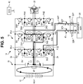
- FIG. 5 is a diagram illustrating a circuit state in which charging of the capacitor C2 is in the on state when the battery 12 is charged by the DC charger 30 in the boost mode. Further, in FIGS. 4 and 5 , switching elements that are switched on are circled.
- FIG. 6 is a diagram illustrating one example of timings of switching between the state in which the charging of the capacitor C1 is on and the state in which the charging of the capacitor C2 is on.
- a state, in which current flows from the DC charger 30 to the capacitor C1 such that the capacitor C1 is charged in the boost mode is referred to as "the charging of the capacitor C1 is in the on state”.
- a state, in which current flows from the DC charger 30 to the capacitor C2 such that the capacitor C2 is charged in the boost mode is referred to as "the charging of the capacitor C2 is in the on state”.
- the charging control unit 62 executes feedback control (PI control), such that the respective voltages VC1, VC2 of the capacitors C1, C2 are equalized.
- PI control feedback control
- the duty when the charging of the capacitor C1 is in the on state and the duty when the charging of the capacitor C2 is in the on state, as represented by a rectangular pulse in FIG. 6 are calculated using the following equation (1).
- T refers to a carrier cycle.
- a high level of the rectangular pulse means that the charging of the capacitor C1 is in the on state
- a low level of the rectangular pulse means that the charging of the capacitor C2 is in the on state.
- duty K p VC 2 ⁇ VC 1 + K i ⁇ VC 2 ⁇ VC 1 dt
- K p represents a proportional gain
- K i represents an integral gain
- the information on the duty calculated as above is output from the charging control unit 62 to the gate signal generation unit 64.
- the gate signal generation unit 64 In the boost mode, the gate signal generation unit 64 generates a gate signal for switching on and off each switching element of the power converters 18 based on the duty, a carrier cycle duty T, and the like, and outputs the generated gate signal to each switching element, such that the charging of the capacitor C1 or the charging of the capacitor C2 is in the on state.
- the voltages VC1, VC2 of the capacitors C1, C2 are charged with the power from the battery 12 respectively, to be 400V, which is 1/2 of the battery voltage VB (800V).
- the voltage of the DC charger 30 is also set to 400V, which is 1/2 of the battery voltage VB (800V).
- the voltage of the DC charger 30 may be slightly higher than 1/2 of the battery voltage VB.
- the ECU 60 switches the charging of the capacitor C1 to the on state.
- the ECU 60 switches on the second switching element SU2 and the third switching element SU3 in the U-phase arm, and the first switching element SV1 in the V-phase arm, and switches off the remaining switching elements.
- the current output from the P terminal 32P of the DC charger 30 to the intermediate point PV1 of the V-phase arm flows through the first switching element SV1 of the V-phase arm, the capacitor C1, and the second switching element SU2 and the third switching element SU3 of the U-phase arm, and is input from the intermediate point PU2 of the U-phase arm to the N terminal 32N of the DC charger 30.
- the capacitor C1 when the charging of the capacitor C1 is in the on state, the capacitor C1 is charged with the power from the DC charger 30, and thus the voltage VC1 is increased.
- the charging of the capacitor C1 by the DC charger 30 is executed until the charging voltage VH (the voltage VC1 + the voltage VC2) reaches a predetermined voltage that is higher than the battery voltage VB.
- the predetermined voltage may be, for example, higher than 800V.
- the ECU 60 may switch off the first switching element SV1 since current flows through the freewheeling diode thereof. On the other hand, by switching on the first switching element SV1, it is possible to secure durability of the first switching element SV1 when current flows therethrough.
- the ECU 60 switches from the state in which the charging of the capacitor C1 is on to the state in which the charging of the capacitor C2 is on.
- the ECU 60 switches on the fourth switching element SU4 in the U-phase arm, and the second switching element SV2 and the third switching element SV3 in the V-phase arm, and switches off the remaining switching elements.
- the charging voltage VH is higher than the battery voltage VB
- the charging of the capacitor C1 by the DC charger 30 is stopped and the power stored in the capacitor C1 is discharged and input to the battery 12, such that the battery 12 is charged.
- the current output from the P terminal 32P of the DC charger 30 to the intermediate point PV1 of the V-phase arm flows the second switching element SV2 and the third switching element SV3 in the V-phase arm, the capacitor C2, the fourth switching element SU4 in the U-phase arm, and is input from the intermediate point PU2 of the U-phase arm to the N terminal 32N of the DC charger 30.
- the capacitor C2 is charged with the power from the DC charger 30, and thus the voltage VC2 is increased.
- the charging of the capacitor C2 by the DC charger 30 is executed until the charging voltage VH reaches a predetermined voltage that is higher than the battery voltage VB.
- the predetermined voltage may be, for example, higher than 800V Thereafter, when determining that the sum of the voltages VC1, VC2 exceeds 800V based on the values of the voltages VC1, VC2 output from the voltmeter provided in the capacitor unit 16, the charging control unit 62 ends the charging of the capacitor C2 by the DC charger 30.
- the ECU 60 may switch off the fourth switching element SU4 since current flows through the freewheeling diode thereof.
- the ECU 60 may switch off the fourth switching element SU4 since current flows through the freewheeling diode thereof.
- the fourth switching element SU4 it is possible to secure durability of the fourth switching element SU4 when current flows therethrough.
- the ECU 60 switches from the state in which the charging of the capacitor C2 is on to the state in which the charging of the capacitor C1 is on. As such, in a state in which the charging voltage VH is higher than the battery voltage VB, the charging of the capacitor C2 by the DC charger 30 is stopped, and the power stored in the capacitor C2 is discharged and input to the battery 12, such that the battery 12 is charged.
- FIG. 7A is a graph illustrating changes of the battery voltage VB and the voltages VC1, VC2 of the capacitors C1, C2 over time during the boost mode.
- FIG. 7B is a graph illustrating a change of currents IC1, IC2 flowing through the capacitors C1, C2 over time during the boost mode.
- the capacitors C1, C2 are charged on the positive current side with respect to 0A, and the capacitors C1, C2 are discharged on the negative current side with respect to 0A.
- boost is not executed using a coil of the motor generator 20 as a reactor. For this reason, since the motor generator 20 is not rotated during charging in the boost mode, it is not necessary to provide a relay that can shut off power supply between the power supply device 10 and the motor generator 20, such that it is possible to achieve reduction in cost and size.
- the battery 12 which is a high-voltage battery, can be charged by both of the DC chargers 30 having, for example, a 400V class and an 800V class corresponding to a plurality of voltage standards.
- the power converter 18 may be configured using an inverter having a greater number of levels than the three-level inverter.
- the P terminal 32P and the N terminal 32N of the DC charger 30 are electrically connected between switching elements different from the switching elements that output power from the power converter 18 to the motor generator 20.
Landscapes
- Engineering & Computer Science (AREA)
- Power Engineering (AREA)
- Transportation (AREA)
- Mechanical Engineering (AREA)
- Electric Propulsion And Braking For Vehicles (AREA)
- Charge And Discharge Circuits For Batteries Or The Like (AREA)
- Control Of Ac Motors In General (AREA)
- Inverter Devices (AREA)
Claims (6)
- Stromsystem, das Folgendes umfasst:ein Gleichstrom-Ladegerät (30); undeine Stromversorgungsvorrichtung (10), die Folgendes umfasst:eine Speicherbatterie (12);eine Kondensatoreinheit (16), in der ein erster Kondensator (C1) und ein zweiter Kondensator (C2) zwischen einem Pluspol (22) und einem Minuspol (24) der Speicherbatterie (12) in Reihe geschaltet sind;einen Stromrichter (18) mit einer U-Phase, einer V-Phase und einer W-Phase, die parallel an die Speicherbatterie (12) angeschlossen sind, wobei die U-Phase, die V-Phase und die W-Phase jeweils Dreistufen-Wechselrichter sind und jeder der Dreistufen-Wechselrichter Folgendes umfasst:ein erstes Schaltelement (SW1; SU1; SV1), ein zweites Schaltelement (SW2; SU2; SV2), ein drittes Schaltelement (SW3; SU3; SV3) und ein viertes Schaltelement (SW4; SU4; SV4) in Reihe geschaltet;eine erste Diode (DW1; DU1; DV1), deren Kathode mit einer Verdrahtung verbunden ist, die das erste Schaltelement (SW1; SU1; SV1) und das zweite Schaltelement (SW2; SU2; SV2) verbindet, und deren Anode mit einer Verdrahtung verbunden ist, die den ersten Kondensator (C1) und den zweiten Kondensator (C2) verbindet; undeine zweite Diode (DW2; DU2; DV2), von der eine Anode mit einer Verdrahtung verbunden ist, die das dritte Schaltelement (SW3; SU3; SV3) und das vierte Schaltelement (SW4; SU4; SV4) verbindet und deren Kathode mit einer den ersten Kondensator (C1) und den zweiten Kondensator (C2) verbindenden Verdrahtung verbunden ist, wobei jeder der Dreistufen-Wechselrichter so ausgebildet ist, dass er selektiv eine Spannung mit einem von drei verschiedenen Spannungswerten an einen Motorgenerator (20) ausgibt, indem er jedes Schaltelement des ersten Schaltelements (SW1; SU1; SV1), des zweiten Schaltelements (SW2; SU2; SV2), des dritten Schaltelements (SW3; SU3; SV3) und des vierten Schaltelements (SW4; SU4; SV4) ein- und ausschaltet;eine Steuervorrichtung (60), die so ausgebildet ist, dass sie ein Ein- und Ausschalten jedes des ersten Schaltelements (SW1; SU1; SV1), des zweiten Schaltelements (SW2; SU2; SV2), des dritten Schaltelements (SW3; SU3; SV3) und des vierten Schaltelements (SW4; SU4; SV4) des Stromrichters (18) steuert;eine erste Anschlussklemme (PW1; PU1; PV1), die elektrisch mit einer P-Klemme (32P) des Gleichstromladegerätes (30) über ein erstes Laderelais (42P) verbunden ist und zwischen dem ersten Schaltelement (SW1; SU1; SV1) und dem zweiten Schaltelement (SW2; SU2; SV2) in der U-Phase, der V-Phase oder der W-Phase angeordnet ist; undeine zweite Anschlussklemme (PW2; PU2; PV2), die über ein zweites Laderelais (42N) elektrisch mit einer N-Klemme (32N) des Gleichstromladegerätes (30) verbunden ist und zwischen dem dritten Schaltelement (SW3; SU3; SV3) und dem vierten Schaltelement (SW4; SU4; SV4) in einer anderen der U-Phase, der V-Phase und der W-Phase angeordnet ist.
- Stromsystem nach Anspruch 1, wobei ein Steuermodus der Steuervorrichtung (60) Folgendes umfasst: einen ersten Lademodus, in dem die Speicherbatterie (12) ohne Leistungsverstärkung durch das Gleichstromladegerät (30) geladen wird, und einen zweiten Lademodus, in dem die Speicherbatterie (12) durch Leistungsverstärkung durch das Gleichstromladegerät (30) geladen wird.
- Stromsystem nach Anspruch 2, wobei die Steuervorrichtung (60) so ausgebildet ist, dass sie im zweiten Lademodus das Ein- und Ausschalten jedes des ersten Schaltelements (SW1; SU1; SV1), des zweiten Schaltelements (SW2; SU2; SV2), des dritten Schaltelements (SW3; SU3; SV3) und des vierten Schaltelements (SW4; SU4; SV4) des Stromrichters (18) steuert, so dass der erste Kondensator (C1) und der zweite Kondensator (C2) abwechselnd mit dem Strom von dem Gleichstromladegerät (30) geladen werden.
- Stromsystem nach Anspruch 3, wobei die Steuervorrichtung (60) für Folgendes ausgebildet ist:wenn der erste Kondensator (C1) mit dem Strom aus dem Gleichstrom-Ladegerät (30) geladen wird,Einschalten des ersten Schaltelements (SW1; SU1; SV1) in einer Phase mit der ersten Anschlussklemme (PW1; PU1; PV1) aus der U-Phase, der V-Phase und der W-Phase und des zweiten Schaltelements (SW2; SU2; SV2) und des dritten Schaltelements (SW3; SU3; SV3) in einer anderen Phase mit der zweiten Anschlussklemme (PW2; PU2; PV2), undAusschalten der übrigen Schaltelemente,und wenn der zweite Kondensator (C2) mit dem Strom aus dem Gleichstrom-Ladegerät (30) geladen wird,Einschalten des zweiten Schaltelements (SW2; SU2; SV2) und des dritten Schaltelements (SW3; SU3; SV3) in der einen Phase mit der ersten Anschlussklemme (PW1; PU1; PV1) aus der U-Phase, der V-Phase und der W-Phase und des vierten Schaltelements (SW4; SU4; SV4) in der anderen Phase mit der zweiten Anschlussklemme (PW2; PU2; PV2), undAusschalten der übrigen Schaltelemente.
- Stromsystem nach einem der Ansprüche 2 bis 4, wobei die Steuervorrichtung (60) so ausgebildet ist, dass sie während des ersten Lademodus Folgendes tut:Aufrechterhalten von Einschaltzuständen des ersten Schaltelements (SW1; SU1; SV1) in einer Phase mit der ersten Anschlussklemme (PW1; PU1; PV1) aus der U-Phase, der V-Phase und der W-Phase und des vierten Schaltelements (SW4; SU4; SV4) in einer anderen Phase mit der zweiten Anschlussklemme (PW2; PU2; PV2), undAufrechterhalten des Aus-Zustands der übrigen Schaltelemente.
- Stromversorgungsvorrichtung (10), die Folgendes umfasst:eine Speicherbatterie (12);eine Kondensatoreinheit (16), in der ein erster Kondensator (C1) und ein zweiter Kondensator (C2) zwischen einem Pluspol (22) und einem Minuspol (24) der Speicherbatterie (12) in Reihe geschaltet sind;einen Stromrichter (18) mit einer U-Phase, einer V-Phase und einer W-Phase, die parallel an die Speicherbatterie (12) angeschlossen sind, wobei die U-Phase, die V-Phase und die W-Phase jeweils Dreistufen-Wechselrichter sind und jeder der Dreistufen-Wechselrichter Folgendes umfasst:ein erstes Schaltelement (SW1; SU1; SV1), ein zweites Schaltelement (SW2; SU2; SV2), ein drittes Schaltelement (SW3; SU3; SV3) und ein viertes Schaltelement (SW4; SU4; SV4) in Reihe geschaltet;eine erste Diode (DW1; DU1; DV1), deren Kathode mit einer Verdrahtung verbunden ist, die das erste Schaltelement (SW1; SU1; SV1) und das zweite Schaltelement (SW2; SU2; SV2) verbindet, und deren Anode mit einer Verdrahtung verbunden ist, die den ersten Kondensator (C1) und den zweiten Kondensator (C2) verbindet; undeine zweite Diode (DW2; DU2; DV2), von der eine Anode mit einer Verdrahtung verbunden ist, die das dritte Schaltelement (SW3; SU3; SV3) und das vierte Schaltelement (SW4; SU4; SV4) verbindet und deren Kathode mit einer den ersten Kondensator (C1) und den zweiten Kondensator (C2) verbindenden Verdrahtung verbunden ist, wobei jeder der Dreistufen-Wechselrichter so ausgebildet ist, dass er selektiv eine Spannung mit einem von drei verschiedenen Spannungswerten an einen Motorgenerator (20) ausgibt, indem er jedes Schaltelement des ersten Schaltelements (SW1; SU1; SV1), des zweiten Schaltelements (SW2; SU2; SV2), des dritten Schaltelements (SW3; SU3; SV3) und des vierten Schaltelements (SW4; SU4; SV4) ein- und ausschaltet;eine Steuervorrichtung (60), die so ausgebildet ist, dass sie ein Ein- und Ausschalten jedes des ersten Schaltelements (SW1; SU1; SV1), des zweiten Schaltelements (SW2; SU2; SV2), des dritten Schaltelements (SW3; SU3; SV3) und des vierten Schaltelements (SW4; SU4; SV4) des Stromrichters (18) steuert;eine erste Anschlussklemme (PW1; PU1; PV1), die über ein erstes Laderelais (42P) elektrisch mit einer P-Klemme (32P) eines Gleichstromladegerätes (30) verbindbar ist und zwischen dem ersten Schaltelement (SW1; SU1; SV1) und dem zweiten Schaltelement (SW2; SU2; SV2) in der U-Phase, der V-Phase oder der W-Phase angeordnet ist; undeine zweite Anschlussklemme (PW2; PU2; PV2), die mit einer N-Klemme (32N) des Gleichstromladegerätes (30) über ein zweites Laderelais (42N) elektrisch verbindbar ist und zwischen dem dritten Schaltelement (SW3; SU3; SV3) und dem vierten Schaltelement (SW4; SU4; SV4) in einer anderen Phase der U-Phase, der V-Phase und der W-Phase angeordnet ist.
Applications Claiming Priority (1)
| Application Number | Priority Date | Filing Date | Title |
|---|---|---|---|
| JP2019171810A JP7160007B2 (ja) | 2019-09-20 | 2019-09-20 | 電源装置 |
Publications (2)
| Publication Number | Publication Date |
|---|---|
| EP3795409A1 EP3795409A1 (de) | 2021-03-24 |
| EP3795409B1 true EP3795409B1 (de) | 2023-03-15 |
Family
ID=72380968
Family Applications (1)
| Application Number | Title | Priority Date | Filing Date |
|---|---|---|---|
| EP20194559.9A Active EP3795409B1 (de) | 2019-09-20 | 2020-09-04 | Stromversorgungssystem und stromversorgungsvorrichtung |
Country Status (7)
| Country | Link |
|---|---|
| US (1) | US11431184B2 (de) |
| EP (1) | EP3795409B1 (de) |
| JP (1) | JP7160007B2 (de) |
| KR (1) | KR102385473B1 (de) |
| CN (1) | CN112537214B (de) |
| BR (1) | BR102020017408A2 (de) |
| RU (1) | RU2738965C1 (de) |
Families Citing this family (18)
| Publication number | Priority date | Publication date | Assignee | Title |
|---|---|---|---|---|
| DE102018216236B4 (de) * | 2018-09-24 | 2020-12-10 | Vitesco Technologies GmbH | Ladeschaltung für einen fahrzeugseitigen elektrischen Energiespeicher |
| JP7446932B2 (ja) * | 2020-06-25 | 2024-03-11 | 東芝インフラシステムズ株式会社 | 電力変換装置およびスイッチ装置 |
| KR20220005347A (ko) * | 2020-07-06 | 2022-01-13 | 현대자동차주식회사 | 차량의 배터리 충전 장치 및 방법 |
| CN112937332B (zh) | 2021-01-21 | 2025-05-13 | 华为数字能源技术有限公司 | 一种充电系统及电动汽车 |
| DE102021003852A1 (de) * | 2021-07-27 | 2021-09-23 | Daimler Ag | Elektrisches Antriebssystem für ein Fahrzeug und Verfahren zum Betreiben eines entsprechenden elektrischen Antriebssystems |
| DE102021003882A1 (de) * | 2021-07-27 | 2021-09-09 | Daimler Ag | Elektrisches Antriebssystem für ein Fahrzeug, sowie Verfahren zum Betreiben eines elektrischen Antriebssystems |
| DE102021003883A1 (de) * | 2021-07-27 | 2023-02-02 | Mercedes-Benz Group AG | Elektrisches Antriebssystem für ein Fahrzeug, Fahrzeug mit einem entsprechenden elektrischen Antriebssystem sowie Verfahren zum Betreiben eines entsprechenden elektrischen Antriebssystems |
| JP7643285B2 (ja) * | 2021-10-07 | 2025-03-11 | トヨタ自動車株式会社 | 充電装置 |
| JP7711546B2 (ja) * | 2021-10-07 | 2025-07-23 | トヨタ自動車株式会社 | 充電装置 |
| JP7578663B2 (ja) * | 2021-11-08 | 2024-11-06 | 台達電子工業股▲ふん▼有限公司 | モータ駆動機能と電池充放電機能とを有する電源統合システム |
| US20230144929A1 (en) * | 2021-11-08 | 2023-05-11 | Delta Electronics, Inc. | Power integration system with motor drive and battery charging and discharging function |
| JP7446390B2 (ja) * | 2021-11-08 | 2024-03-08 | 台達電子工業股▲ふん▼有限公司 | モータ駆動と電池の充放電を備えた電源統合システム |
| CN118382555A (zh) | 2022-02-17 | 2024-07-23 | 埃沃哥有限责任公司 | 用于高度自动化车辆的动力和致动控制装置 |
| JP7768058B2 (ja) * | 2022-07-08 | 2025-11-12 | 株式会社デンソー | 電力変換装置 |
| JP2024022167A (ja) | 2022-08-05 | 2024-02-16 | トヨタ自動車株式会社 | 電源装置 |
| WO2024248677A1 (ru) * | 2023-06-02 | 2024-12-05 | Общество с ограниченной ответственностью "ЭвоКарго" | Преобразователь напряжения для водородной системы энергоснабжения транспортного средства |
| CN119787290B (zh) * | 2024-12-30 | 2025-11-21 | 中国科学院电工研究所 | 一种中压直流储能系统及控制方法 |
| CN120528073B (zh) * | 2025-07-23 | 2025-09-19 | 西安锐泽克斯光电科技有限公司 | 充电保护电路、充电电路和设备 |
Family Cites Families (17)
| Publication number | Priority date | Publication date | Assignee | Title |
|---|---|---|---|---|
| EP0838855B1 (de) * | 1991-09-20 | 2004-11-24 | Hitachi, Ltd. | Halbleitermodul |
| JP3179692B2 (ja) * | 1995-12-26 | 2001-06-25 | 東洋電機製造株式会社 | スイッチング損失を低減化した3レベルインバータのpwm制御方法および装置 |
| JP4946106B2 (ja) | 2006-03-15 | 2012-06-06 | 日産自動車株式会社 | 電力変換装置 |
| EP1833151B1 (de) * | 2006-03-07 | 2017-06-14 | Nissan Motor Co., Ltd. | Leistungsumwandlungseinrichtung |
| CN101801710B (zh) * | 2007-09-10 | 2012-07-18 | 丰田自动车株式会社 | 车辆的系统起动装置及车辆的系统起动方法 |
| JP5644070B2 (ja) * | 2008-07-16 | 2014-12-24 | 株式会社豊田中央研究所 | 電力制御装置 |
| US8482945B2 (en) * | 2008-09-26 | 2013-07-09 | Merstech, Inc. | Power converter with magnetic recovery switch |
| JP5611684B2 (ja) | 2010-06-22 | 2014-10-22 | 株式会社東芝 | 電力変換装置 |
| US9985524B2 (en) * | 2013-10-30 | 2018-05-29 | Mitsubishi Electric Corporation | DC/DC conversion device and load-drive control system |
| JP6216672B2 (ja) * | 2014-03-27 | 2017-10-18 | 本田技研工業株式会社 | 三相交流発電スタータ装置 |
| JP6406122B2 (ja) | 2015-05-15 | 2018-10-17 | 株式会社デンソー | マルチレベルインバータの制御装置 |
| MX361850B (es) * | 2015-06-23 | 2018-12-18 | Nissan Motor | Inversor con capacidad de carga. |
| DE102016209898A1 (de) * | 2016-06-06 | 2017-12-07 | Continental Automotive Gmbh | Fahrzeugbordnetz mit Wechselrichter, Energiespeicher, elektrischer Maschine und Gleichstrom-Übertragungsanschluss |
| DE102016216324A1 (de) * | 2016-08-30 | 2018-03-01 | Robert Bosch Gmbh | Antriebssystem, insbesondere für ein Fahrzeug, und Verfahren zum Aufheizen eines Antriebssystems |
| DE102016218304B3 (de) * | 2016-09-23 | 2018-02-01 | Volkswagen Aktiengesellschaft | Vorrichtung zur Spannungswandlung, Traktionsnetz und Verfahren zum Laden einer Batterie |
| JP6555244B2 (ja) * | 2016-12-19 | 2019-08-07 | トヨタ自動車株式会社 | 車両 |
| JP2019004593A (ja) * | 2017-06-14 | 2019-01-10 | 本田技研工業株式会社 | 車両の電源装置 |
-
2019
- 2019-09-20 JP JP2019171810A patent/JP7160007B2/ja active Active
-
2020
- 2020-08-26 RU RU2020128389A patent/RU2738965C1/ru active
- 2020-08-26 KR KR1020200107997A patent/KR102385473B1/ko not_active Expired - Fee Related
- 2020-08-26 CN CN202010872554.6A patent/CN112537214B/zh active Active
- 2020-08-26 BR BR102020017408-8A patent/BR102020017408A2/pt not_active Application Discontinuation
- 2020-09-04 EP EP20194559.9A patent/EP3795409B1/de active Active
- 2020-09-08 US US17/014,057 patent/US11431184B2/en active Active
Also Published As
| Publication number | Publication date |
|---|---|
| EP3795409A1 (de) | 2021-03-24 |
| CN112537214B (zh) | 2023-04-07 |
| US20210091573A1 (en) | 2021-03-25 |
| KR102385473B1 (ko) | 2022-04-11 |
| CN112537214A (zh) | 2021-03-23 |
| JP2021048759A (ja) | 2021-03-25 |
| KR20210034484A (ko) | 2021-03-30 |
| RU2738965C1 (ru) | 2020-12-21 |
| JP7160007B2 (ja) | 2022-10-25 |
| US11431184B2 (en) | 2022-08-30 |
| BR102020017408A2 (pt) | 2021-04-13 |
Similar Documents
| Publication | Publication Date | Title |
|---|---|---|
| EP3795409B1 (de) | Stromversorgungssystem und stromversorgungsvorrichtung | |
| JP4800402B2 (ja) | 車両搭載用マルチフェーズコンバータ | |
| EP2364872B1 (de) | Schaltkreis zum Laden von Batterien und Ladeverfahren | |
| US9985524B2 (en) | DC/DC conversion device and load-drive control system | |
| KR20190133396A (ko) | 차량 배터리 충전용 전력 변환 장치 및 이의 제어 방법 | |
| US20190359074A1 (en) | Power supply system for vehicle | |
| US20110011658A1 (en) | Load driving system and electric vehicle using the system | |
| US7605497B2 (en) | Two-source inverter | |
| US11207985B2 (en) | Power supply device | |
| US9843075B2 (en) | Internal energy supply of energy storage modules for an energy storage device, and energy storage device with such an internal energy supply | |
| US7719138B2 (en) | Two-source series inverter | |
| JP2021035202A (ja) | 電源装置 | |
| US7659689B2 (en) | Power conversion apparatus and method and automobile | |
| JP7103320B2 (ja) | 電源装置 | |
| JP7559573B2 (ja) | 電源装置 | |
| JP7643285B2 (ja) | 充電装置 | |
| JP7639349B2 (ja) | 電源装置 | |
| JP7559617B2 (ja) | 電源装置 | |
| JP7711546B2 (ja) | 充電装置 | |
| US20260081440A1 (en) | Power supply system |
Legal Events
| Date | Code | Title | Description |
|---|---|---|---|
| PUAI | Public reference made under article 153(3) epc to a published international application that has entered the european phase |
Free format text: ORIGINAL CODE: 0009012 |
|
| STAA | Information on the status of an ep patent application or granted ep patent |
Free format text: STATUS: REQUEST FOR EXAMINATION WAS MADE |
|
| 17P | Request for examination filed |
Effective date: 20200919 |
|
| AK | Designated contracting states |
Kind code of ref document: A1 Designated state(s): AL AT BE BG CH CY CZ DE DK EE ES FI FR GB GR HR HU IE IS IT LI LT LU LV MC MK MT NL NO PL PT RO RS SE SI SK SM TR |
|
| AX | Request for extension of the european patent |
Extension state: BA ME |
|
| GRAP | Despatch of communication of intention to grant a patent |
Free format text: ORIGINAL CODE: EPIDOSNIGR1 |
|
| STAA | Information on the status of an ep patent application or granted ep patent |
Free format text: STATUS: GRANT OF PATENT IS INTENDED |
|
| RIC1 | Information provided on ipc code assigned before grant |
Ipc: H02M 7/487 20070101ALI20220831BHEP Ipc: H02M 7/483 20070101ALI20220831BHEP Ipc: H02M 3/158 20060101ALI20220831BHEP Ipc: H02J 7/34 20060101ALI20220831BHEP Ipc: H02M 7/48 20070101ALI20220831BHEP Ipc: H02M 1/08 20060101ALI20220831BHEP Ipc: H02M 7/5387 20070101ALI20220831BHEP Ipc: H02J 7/02 20160101ALI20220831BHEP Ipc: B60L 53/24 20190101AFI20220831BHEP |
|
| INTG | Intention to grant announced |
Effective date: 20221004 |
|
| GRAS | Grant fee paid |
Free format text: ORIGINAL CODE: EPIDOSNIGR3 |
|
| GRAA | (expected) grant |
Free format text: ORIGINAL CODE: 0009210 |
|
| STAA | Information on the status of an ep patent application or granted ep patent |
Free format text: STATUS: THE PATENT HAS BEEN GRANTED |
|
| AK | Designated contracting states |
Kind code of ref document: B1 Designated state(s): AL AT BE BG CH CY CZ DE DK EE ES FI FR GB GR HR HU IE IS IT LI LT LU LV MC MK MT NL NO PL PT RO RS SE SI SK SM TR |
|
| REG | Reference to a national code |
Ref country code: CH Ref legal event code: EP Ref country code: GB Ref legal event code: FG4D |
|
| REG | Reference to a national code |
Ref country code: DE Ref legal event code: R096 Ref document number: 602020008833 Country of ref document: DE |
|
| REG | Reference to a national code |
Ref country code: IE Ref legal event code: FG4D |
|
| REG | Reference to a national code |
Ref country code: AT Ref legal event code: REF Ref document number: 1553829 Country of ref document: AT Kind code of ref document: T Effective date: 20230415 |
|
| REG | Reference to a national code |
Ref country code: LT Ref legal event code: MG9D |
|
| REG | Reference to a national code |
Ref country code: NL Ref legal event code: MP Effective date: 20230315 |
|
| PG25 | Lapsed in a contracting state [announced via postgrant information from national office to epo] |
Ref country code: RS Free format text: LAPSE BECAUSE OF FAILURE TO SUBMIT A TRANSLATION OF THE DESCRIPTION OR TO PAY THE FEE WITHIN THE PRESCRIBED TIME-LIMIT Effective date: 20230315 Ref country code: NO Free format text: LAPSE BECAUSE OF FAILURE TO SUBMIT A TRANSLATION OF THE DESCRIPTION OR TO PAY THE FEE WITHIN THE PRESCRIBED TIME-LIMIT Effective date: 20230615 Ref country code: LV Free format text: LAPSE BECAUSE OF FAILURE TO SUBMIT A TRANSLATION OF THE DESCRIPTION OR TO PAY THE FEE WITHIN THE PRESCRIBED TIME-LIMIT Effective date: 20230315 Ref country code: LT Free format text: LAPSE BECAUSE OF FAILURE TO SUBMIT A TRANSLATION OF THE DESCRIPTION OR TO PAY THE FEE WITHIN THE PRESCRIBED TIME-LIMIT Effective date: 20230315 Ref country code: HR Free format text: LAPSE BECAUSE OF FAILURE TO SUBMIT A TRANSLATION OF THE DESCRIPTION OR TO PAY THE FEE WITHIN THE PRESCRIBED TIME-LIMIT Effective date: 20230315 |
|
| REG | Reference to a national code |
Ref country code: AT Ref legal event code: MK05 Ref document number: 1553829 Country of ref document: AT Kind code of ref document: T Effective date: 20230315 |
|
| REG | Reference to a national code |
Ref country code: DE Ref legal event code: R084 Ref document number: 602020008833 Country of ref document: DE |
|
| PG25 | Lapsed in a contracting state [announced via postgrant information from national office to epo] |
Ref country code: SE Free format text: LAPSE BECAUSE OF FAILURE TO SUBMIT A TRANSLATION OF THE DESCRIPTION OR TO PAY THE FEE WITHIN THE PRESCRIBED TIME-LIMIT Effective date: 20230315 Ref country code: NL Free format text: LAPSE BECAUSE OF FAILURE TO SUBMIT A TRANSLATION OF THE DESCRIPTION OR TO PAY THE FEE WITHIN THE PRESCRIBED TIME-LIMIT Effective date: 20230315 Ref country code: GR Free format text: LAPSE BECAUSE OF FAILURE TO SUBMIT A TRANSLATION OF THE DESCRIPTION OR TO PAY THE FEE WITHIN THE PRESCRIBED TIME-LIMIT Effective date: 20230616 Ref country code: FI Free format text: LAPSE BECAUSE OF FAILURE TO SUBMIT A TRANSLATION OF THE DESCRIPTION OR TO PAY THE FEE WITHIN THE PRESCRIBED TIME-LIMIT Effective date: 20230315 |
|
| PG25 | Lapsed in a contracting state [announced via postgrant information from national office to epo] |
Ref country code: SM Free format text: LAPSE BECAUSE OF FAILURE TO SUBMIT A TRANSLATION OF THE DESCRIPTION OR TO PAY THE FEE WITHIN THE PRESCRIBED TIME-LIMIT Effective date: 20230315 Ref country code: RO Free format text: LAPSE BECAUSE OF FAILURE TO SUBMIT A TRANSLATION OF THE DESCRIPTION OR TO PAY THE FEE WITHIN THE PRESCRIBED TIME-LIMIT Effective date: 20230315 Ref country code: PT Free format text: LAPSE BECAUSE OF FAILURE TO SUBMIT A TRANSLATION OF THE DESCRIPTION OR TO PAY THE FEE WITHIN THE PRESCRIBED TIME-LIMIT Effective date: 20230717 Ref country code: ES Free format text: LAPSE BECAUSE OF FAILURE TO SUBMIT A TRANSLATION OF THE DESCRIPTION OR TO PAY THE FEE WITHIN THE PRESCRIBED TIME-LIMIT Effective date: 20230315 Ref country code: EE Free format text: LAPSE BECAUSE OF FAILURE TO SUBMIT A TRANSLATION OF THE DESCRIPTION OR TO PAY THE FEE WITHIN THE PRESCRIBED TIME-LIMIT Effective date: 20230315 Ref country code: CZ Free format text: LAPSE BECAUSE OF FAILURE TO SUBMIT A TRANSLATION OF THE DESCRIPTION OR TO PAY THE FEE WITHIN THE PRESCRIBED TIME-LIMIT Effective date: 20230315 Ref country code: AT Free format text: LAPSE BECAUSE OF FAILURE TO SUBMIT A TRANSLATION OF THE DESCRIPTION OR TO PAY THE FEE WITHIN THE PRESCRIBED TIME-LIMIT Effective date: 20230315 |
|
| P01 | Opt-out of the competence of the unified patent court (upc) registered |
Effective date: 20231024 |
|
| PG25 | Lapsed in a contracting state [announced via postgrant information from national office to epo] |
Ref country code: SK Free format text: LAPSE BECAUSE OF FAILURE TO SUBMIT A TRANSLATION OF THE DESCRIPTION OR TO PAY THE FEE WITHIN THE PRESCRIBED TIME-LIMIT Effective date: 20230315 Ref country code: PL Free format text: LAPSE BECAUSE OF FAILURE TO SUBMIT A TRANSLATION OF THE DESCRIPTION OR TO PAY THE FEE WITHIN THE PRESCRIBED TIME-LIMIT Effective date: 20230315 Ref country code: IS Free format text: LAPSE BECAUSE OF FAILURE TO SUBMIT A TRANSLATION OF THE DESCRIPTION OR TO PAY THE FEE WITHIN THE PRESCRIBED TIME-LIMIT Effective date: 20230715 |
|
| REG | Reference to a national code |
Ref country code: DE Ref legal event code: R097 Ref document number: 602020008833 Country of ref document: DE |
|
| PLBE | No opposition filed within time limit |
Free format text: ORIGINAL CODE: 0009261 |
|
| STAA | Information on the status of an ep patent application or granted ep patent |
Free format text: STATUS: NO OPPOSITION FILED WITHIN TIME LIMIT |
|
| PG25 | Lapsed in a contracting state [announced via postgrant information from national office to epo] |
Ref country code: SI Free format text: LAPSE BECAUSE OF FAILURE TO SUBMIT A TRANSLATION OF THE DESCRIPTION OR TO PAY THE FEE WITHIN THE PRESCRIBED TIME-LIMIT Effective date: 20230315 Ref country code: DK Free format text: LAPSE BECAUSE OF FAILURE TO SUBMIT A TRANSLATION OF THE DESCRIPTION OR TO PAY THE FEE WITHIN THE PRESCRIBED TIME-LIMIT Effective date: 20230315 |
|
| 26N | No opposition filed |
Effective date: 20231218 |
|
| REG | Reference to a national code |
Ref country code: CH Ref legal event code: PL |
|
| PG25 | Lapsed in a contracting state [announced via postgrant information from national office to epo] |
Ref country code: LU Free format text: LAPSE BECAUSE OF NON-PAYMENT OF DUE FEES Effective date: 20230904 |
|
| REG | Reference to a national code |
Ref country code: BE Ref legal event code: MM Effective date: 20230930 |
|
| PG25 | Lapsed in a contracting state [announced via postgrant information from national office to epo] |
Ref country code: LU Free format text: LAPSE BECAUSE OF NON-PAYMENT OF DUE FEES Effective date: 20230904 Ref country code: IT Free format text: LAPSE BECAUSE OF FAILURE TO SUBMIT A TRANSLATION OF THE DESCRIPTION OR TO PAY THE FEE WITHIN THE PRESCRIBED TIME-LIMIT Effective date: 20230315 Ref country code: MC Free format text: LAPSE BECAUSE OF FAILURE TO SUBMIT A TRANSLATION OF THE DESCRIPTION OR TO PAY THE FEE WITHIN THE PRESCRIBED TIME-LIMIT Effective date: 20230315 |
|
| REG | Reference to a national code |
Ref country code: IE Ref legal event code: MM4A |
|
| PG25 | Lapsed in a contracting state [announced via postgrant information from national office to epo] |
Ref country code: IE Free format text: LAPSE BECAUSE OF NON-PAYMENT OF DUE FEES Effective date: 20230904 |
|
| PG25 | Lapsed in a contracting state [announced via postgrant information from national office to epo] |
Ref country code: CH Free format text: LAPSE BECAUSE OF NON-PAYMENT OF DUE FEES Effective date: 20230930 |
|
| PG25 | Lapsed in a contracting state [announced via postgrant information from national office to epo] |
Ref country code: IE Free format text: LAPSE BECAUSE OF NON-PAYMENT OF DUE FEES Effective date: 20230904 Ref country code: FR Free format text: LAPSE BECAUSE OF NON-PAYMENT OF DUE FEES Effective date: 20230930 Ref country code: CH Free format text: LAPSE BECAUSE OF NON-PAYMENT OF DUE FEES Effective date: 20230930 |
|
| PG25 | Lapsed in a contracting state [announced via postgrant information from national office to epo] |
Ref country code: BE Free format text: LAPSE BECAUSE OF NON-PAYMENT OF DUE FEES Effective date: 20230930 |
|
| PG25 | Lapsed in a contracting state [announced via postgrant information from national office to epo] |
Ref country code: BG Free format text: LAPSE BECAUSE OF FAILURE TO SUBMIT A TRANSLATION OF THE DESCRIPTION OR TO PAY THE FEE WITHIN THE PRESCRIBED TIME-LIMIT Effective date: 20230315 |
|
| PG25 | Lapsed in a contracting state [announced via postgrant information from national office to epo] |
Ref country code: BG Free format text: LAPSE BECAUSE OF FAILURE TO SUBMIT A TRANSLATION OF THE DESCRIPTION OR TO PAY THE FEE WITHIN THE PRESCRIBED TIME-LIMIT Effective date: 20230315 |
|
| GBPC | Gb: european patent ceased through non-payment of renewal fee |
Effective date: 20240904 |
|
| PG25 | Lapsed in a contracting state [announced via postgrant information from national office to epo] |
Ref country code: GB Free format text: LAPSE BECAUSE OF NON-PAYMENT OF DUE FEES Effective date: 20240904 |
|
| PG25 | Lapsed in a contracting state [announced via postgrant information from national office to epo] |
Ref country code: CY Free format text: LAPSE BECAUSE OF FAILURE TO SUBMIT A TRANSLATION OF THE DESCRIPTION OR TO PAY THE FEE WITHIN THE PRESCRIBED TIME-LIMIT; INVALID AB INITIO Effective date: 20200904 |
|
| PG25 | Lapsed in a contracting state [announced via postgrant information from national office to epo] |
Ref country code: HU Free format text: LAPSE BECAUSE OF FAILURE TO SUBMIT A TRANSLATION OF THE DESCRIPTION OR TO PAY THE FEE WITHIN THE PRESCRIBED TIME-LIMIT; INVALID AB INITIO Effective date: 20200904 |
|
| PGFP | Annual fee paid to national office [announced via postgrant information from national office to epo] |
Ref country code: DE Payment date: 20250730 Year of fee payment: 6 |
|
| PG25 | Lapsed in a contracting state [announced via postgrant information from national office to epo] |
Ref country code: TR Free format text: LAPSE BECAUSE OF FAILURE TO SUBMIT A TRANSLATION OF THE DESCRIPTION OR TO PAY THE FEE WITHIN THE PRESCRIBED TIME-LIMIT Effective date: 20230315 |