EP3795101B1 - Chirurgisches ultraschallinstrument mit wandlersperrfunktion - Google Patents
Chirurgisches ultraschallinstrument mit wandlersperrfunktion Download PDFInfo
- Publication number
- EP3795101B1 EP3795101B1 EP20205500.0A EP20205500A EP3795101B1 EP 3795101 B1 EP3795101 B1 EP 3795101B1 EP 20205500 A EP20205500 A EP 20205500A EP 3795101 B1 EP3795101 B1 EP 3795101B1
- Authority
- EP
- European Patent Office
- Prior art keywords
- lock
- transducer assembly
- torque
- knob
- assembly
- Prior art date
- Legal status (The legal status is an assumption and is not a legal conclusion. Google has not performed a legal analysis and makes no representation as to the accuracy of the status listed.)
- Active
Links
Images


Classifications
-
- A—HUMAN NECESSITIES
- A61—MEDICAL OR VETERINARY SCIENCE; HYGIENE
- A61B—DIAGNOSIS; SURGERY; IDENTIFICATION
- A61B17/00—Surgical instruments, devices or methods
- A61B17/32—Surgical cutting instruments
- A61B17/320068—Surgical cutting instruments using mechanical vibrations, e.g. ultrasonic
-
- A—HUMAN NECESSITIES
- A61—MEDICAL OR VETERINARY SCIENCE; HYGIENE
- A61B—DIAGNOSIS; SURGERY; IDENTIFICATION
- A61B90/00—Instruments, implements or accessories specially adapted for surgery or diagnosis and not covered by any of the groups A61B1/00 - A61B50/00, e.g. for luxation treatment or for protecting wound edges
- A61B90/03—Automatic limiting or abutting means, e.g. for safety
-
- A—HUMAN NECESSITIES
- A61—MEDICAL OR VETERINARY SCIENCE; HYGIENE
- A61B—DIAGNOSIS; SURGERY; IDENTIFICATION
- A61B1/00—Instruments for performing medical examinations of the interior of cavities or tubes of the body by visual or photographical inspection, e.g. endoscopes; Illuminating arrangements therefor
- A61B1/00002—Operational features of endoscopes
- A61B1/00039—Operational features of endoscopes provided with input arrangements for the user
- A61B1/00042—Operational features of endoscopes provided with input arrangements for the user for mechanical operation
-
- A—HUMAN NECESSITIES
- A61—MEDICAL OR VETERINARY SCIENCE; HYGIENE
- A61B—DIAGNOSIS; SURGERY; IDENTIFICATION
- A61B17/00—Surgical instruments, devices or methods
- A61B17/32—Surgical cutting instruments
- A61B17/320068—Surgical cutting instruments using mechanical vibrations, e.g. ultrasonic
- A61B17/320092—Surgical cutting instruments using mechanical vibrations, e.g. ultrasonic with additional movable means for clamping or cutting tissue, e.g. with a pivoting jaw
-
- A—HUMAN NECESSITIES
- A61—MEDICAL OR VETERINARY SCIENCE; HYGIENE
- A61B—DIAGNOSIS; SURGERY; IDENTIFICATION
- A61B18/00—Surgical instruments, devices or methods for transferring non-mechanical forms of energy to or from the body
-
- A—HUMAN NECESSITIES
- A61—MEDICAL OR VETERINARY SCIENCE; HYGIENE
- A61B—DIAGNOSIS; SURGERY; IDENTIFICATION
- A61B18/00—Surgical instruments, devices or methods for transferring non-mechanical forms of energy to or from the body
- A61B18/04—Surgical instruments, devices or methods for transferring non-mechanical forms of energy to or from the body by heating
- A61B18/12—Surgical instruments, devices or methods for transferring non-mechanical forms of energy to or from the body by heating by passing a current through the tissue to be heated, e.g. high-frequency current
- A61B18/14—Probes or electrodes therefor
- A61B18/1442—Probes having pivoting end effectors, e.g. forceps
-
- A—HUMAN NECESSITIES
- A61—MEDICAL OR VETERINARY SCIENCE; HYGIENE
- A61N—ELECTROTHERAPY; MAGNETOTHERAPY; RADIATION THERAPY; ULTRASOUND THERAPY
- A61N7/00—Ultrasound therapy
- A61N7/02—Localised ultrasound hyperthermia
-
- A—HUMAN NECESSITIES
- A61—MEDICAL OR VETERINARY SCIENCE; HYGIENE
- A61B—DIAGNOSIS; SURGERY; IDENTIFICATION
- A61B17/00—Surgical instruments, devices or methods
- A61B2017/00367—Details of actuation of instruments, e.g. relations between pushing buttons, or the like, and activation of the tool, working tip, or the like
- A61B2017/00398—Details of actuation of instruments, e.g. relations between pushing buttons, or the like, and activation of the tool, working tip, or the like using powered actuators, e.g. stepper motors, solenoids
-
- A—HUMAN NECESSITIES
- A61—MEDICAL OR VETERINARY SCIENCE; HYGIENE
- A61B—DIAGNOSIS; SURGERY; IDENTIFICATION
- A61B17/00—Surgical instruments, devices or methods
- A61B2017/0046—Surgical instruments, devices or methods with a releasable handle; with handle and operating part separable
-
- A—HUMAN NECESSITIES
- A61—MEDICAL OR VETERINARY SCIENCE; HYGIENE
- A61B—DIAGNOSIS; SURGERY; IDENTIFICATION
- A61B17/00—Surgical instruments, devices or methods
- A61B2017/00477—Coupling
-
- A—HUMAN NECESSITIES
- A61—MEDICAL OR VETERINARY SCIENCE; HYGIENE
- A61B—DIAGNOSIS; SURGERY; IDENTIFICATION
- A61B17/00—Surgical instruments, devices or methods
- A61B17/28—Surgical forceps
- A61B17/29—Forceps for use in minimally invasive surgery
- A61B2017/2926—Details of heads or jaws
- A61B2017/2927—Details of heads or jaws the angular position of the head being adjustable with respect to the shaft
- A61B2017/2929—Details of heads or jaws the angular position of the head being adjustable with respect to the shaft with a head rotatable about the longitudinal axis of the shaft
- A61B2017/293—Details of heads or jaws the angular position of the head being adjustable with respect to the shaft with a head rotatable about the longitudinal axis of the shaft with means preventing relative rotation between the shaft and the actuating rod
-
- A—HUMAN NECESSITIES
- A61—MEDICAL OR VETERINARY SCIENCE; HYGIENE
- A61B—DIAGNOSIS; SURGERY; IDENTIFICATION
- A61B17/00—Surgical instruments, devices or methods
- A61B17/28—Surgical forceps
- A61B17/29—Forceps for use in minimally invasive surgery
- A61B2017/2946—Locking means
-
- A—HUMAN NECESSITIES
- A61—MEDICAL OR VETERINARY SCIENCE; HYGIENE
- A61B—DIAGNOSIS; SURGERY; IDENTIFICATION
- A61B17/00—Surgical instruments, devices or methods
- A61B17/32—Surgical cutting instruments
- A61B17/320068—Surgical cutting instruments using mechanical vibrations, e.g. ultrasonic
- A61B2017/320069—Surgical cutting instruments using mechanical vibrations, e.g. ultrasonic for ablating tissue
-
- A—HUMAN NECESSITIES
- A61—MEDICAL OR VETERINARY SCIENCE; HYGIENE
- A61B—DIAGNOSIS; SURGERY; IDENTIFICATION
- A61B17/00—Surgical instruments, devices or methods
- A61B17/32—Surgical cutting instruments
- A61B17/320068—Surgical cutting instruments using mechanical vibrations, e.g. ultrasonic
- A61B2017/320071—Surgical cutting instruments using mechanical vibrations, e.g. ultrasonic with articulating means for working tip
-
- A—HUMAN NECESSITIES
- A61—MEDICAL OR VETERINARY SCIENCE; HYGIENE
- A61B—DIAGNOSIS; SURGERY; IDENTIFICATION
- A61B17/00—Surgical instruments, devices or methods
- A61B17/32—Surgical cutting instruments
- A61B17/320068—Surgical cutting instruments using mechanical vibrations, e.g. ultrasonic
- A61B2017/320082—Surgical cutting instruments using mechanical vibrations, e.g. ultrasonic for incising tissue
-
- A—HUMAN NECESSITIES
- A61—MEDICAL OR VETERINARY SCIENCE; HYGIENE
- A61B—DIAGNOSIS; SURGERY; IDENTIFICATION
- A61B17/00—Surgical instruments, devices or methods
- A61B17/32—Surgical cutting instruments
- A61B17/320068—Surgical cutting instruments using mechanical vibrations, e.g. ultrasonic
- A61B17/320092—Surgical cutting instruments using mechanical vibrations, e.g. ultrasonic with additional movable means for clamping or cutting tissue, e.g. with a pivoting jaw
- A61B2017/320094—Surgical cutting instruments using mechanical vibrations, e.g. ultrasonic with additional movable means for clamping or cutting tissue, e.g. with a pivoting jaw additional movable means performing clamping operation
-
- A—HUMAN NECESSITIES
- A61—MEDICAL OR VETERINARY SCIENCE; HYGIENE
- A61B—DIAGNOSIS; SURGERY; IDENTIFICATION
- A61B17/00—Surgical instruments, devices or methods
- A61B17/32—Surgical cutting instruments
- A61B17/320068—Surgical cutting instruments using mechanical vibrations, e.g. ultrasonic
- A61B17/320092—Surgical cutting instruments using mechanical vibrations, e.g. ultrasonic with additional movable means for clamping or cutting tissue, e.g. with a pivoting jaw
- A61B2017/320095—Surgical cutting instruments using mechanical vibrations, e.g. ultrasonic with additional movable means for clamping or cutting tissue, e.g. with a pivoting jaw with sealing or cauterizing means
-
- A—HUMAN NECESSITIES
- A61—MEDICAL OR VETERINARY SCIENCE; HYGIENE
- A61B—DIAGNOSIS; SURGERY; IDENTIFICATION
- A61B18/00—Surgical instruments, devices or methods for transferring non-mechanical forms of energy to or from the body
- A61B2018/00315—Surgical instruments, devices or methods for transferring non-mechanical forms of energy to or from the body for treatment of particular body parts
- A61B2018/00345—Vascular system
-
- A—HUMAN NECESSITIES
- A61—MEDICAL OR VETERINARY SCIENCE; HYGIENE
- A61B—DIAGNOSIS; SURGERY; IDENTIFICATION
- A61B18/00—Surgical instruments, devices or methods for transferring non-mechanical forms of energy to or from the body
- A61B2018/00571—Surgical instruments, devices or methods for transferring non-mechanical forms of energy to or from the body for achieving a particular surgical effect
- A61B2018/00589—Coagulation
-
- A—HUMAN NECESSITIES
- A61—MEDICAL OR VETERINARY SCIENCE; HYGIENE
- A61B—DIAGNOSIS; SURGERY; IDENTIFICATION
- A61B18/00—Surgical instruments, devices or methods for transferring non-mechanical forms of energy to or from the body
- A61B2018/00571—Surgical instruments, devices or methods for transferring non-mechanical forms of energy to or from the body for achieving a particular surgical effect
- A61B2018/00601—Cutting
-
- A—HUMAN NECESSITIES
- A61—MEDICAL OR VETERINARY SCIENCE; HYGIENE
- A61B—DIAGNOSIS; SURGERY; IDENTIFICATION
- A61B18/00—Surgical instruments, devices or methods for transferring non-mechanical forms of energy to or from the body
- A61B2018/00571—Surgical instruments, devices or methods for transferring non-mechanical forms of energy to or from the body for achieving a particular surgical effect
- A61B2018/00619—Welding
-
- A—HUMAN NECESSITIES
- A61—MEDICAL OR VETERINARY SCIENCE; HYGIENE
- A61B—DIAGNOSIS; SURGERY; IDENTIFICATION
- A61B18/00—Surgical instruments, devices or methods for transferring non-mechanical forms of energy to or from the body
- A61B2018/00571—Surgical instruments, devices or methods for transferring non-mechanical forms of energy to or from the body for achieving a particular surgical effect
- A61B2018/0063—Sealing
-
- A—HUMAN NECESSITIES
- A61—MEDICAL OR VETERINARY SCIENCE; HYGIENE
- A61B—DIAGNOSIS; SURGERY; IDENTIFICATION
- A61B18/00—Surgical instruments, devices or methods for transferring non-mechanical forms of energy to or from the body
- A61B18/04—Surgical instruments, devices or methods for transferring non-mechanical forms of energy to or from the body by heating
- A61B18/12—Surgical instruments, devices or methods for transferring non-mechanical forms of energy to or from the body by heating by passing a current through the tissue to be heated, e.g. high-frequency current
- A61B18/14—Probes or electrodes therefor
- A61B18/1442—Probes having pivoting end effectors, e.g. forceps
- A61B2018/1452—Probes having pivoting end effectors, e.g. forceps including means for cutting
-
- A—HUMAN NECESSITIES
- A61—MEDICAL OR VETERINARY SCIENCE; HYGIENE
- A61B—DIAGNOSIS; SURGERY; IDENTIFICATION
- A61B90/00—Instruments, implements or accessories specially adapted for surgery or diagnosis and not covered by any of the groups A61B1/00 - A61B50/00, e.g. for luxation treatment or for protecting wound edges
- A61B90/03—Automatic limiting or abutting means, e.g. for safety
- A61B2090/031—Automatic limiting or abutting means, e.g. for safety torque limiting
Definitions
- a variety of surgical instruments include an end effector having a blade element that vibrates at ultrasonic frequencies to cut and/or seal tissue (e.g., by denaturing proteins in tissue cells). These instruments include piezoelectric elements that convert electrical power into ultrasonic vibrations, which are communicated along an acoustic waveguide to the blade element. The precision of cutting and coagulation may be controlled by the surgeon's technique and adjusting the power level, blade edge, tissue traction and blade pressure.
- ultrasonic surgical instruments examples include the HARMONIC ACE ® Ultrasonic Shears, the HARMONIC WAVE ® Ultrasonic Shears, the HARMONIC FOCUS ® Ultrasonic Shears, and the HARMONIC SYNERGY ® Ultrasonic Blades, all by Ethicon Endo-Surgery, Inc. of Cincinnati, Ohio. Further examples of such devices and related concepts are disclosed in U.S. Pat. No. 5,322,055, entitled "Clamp Coagulator/Cutting System for Ultrasonic Surgical Instruments," issued June 21, 1994 ; U.S. Pat. No.
- Some ultrasonic surgical instruments may include a cordless transducer such as that disclosed in U.S. Pub. No. 2012/0112687, entitled “Recharge System for Medical Devices,” published May 10, 2012 ; U.S. Pub. No. 2012/0116265, entitled “Surgical Instrument with Charging Devices,” published May 10, 2012 ; and/or U.S. Pat. App. No. 61/410,603, filed November 5, 2010 , entitled “Energy- Based Surgical Instruments”.
- ultrasonic surgical instruments may include an articulating shaft section and/or a bendable ultrasonic waveguide. Examples of such ultrasonic surgical instruments are disclosed in U.S. Pat. No. 5,897,523, entitled “Articulating Ultrasonic Surgical Instrument,” issued April 27, 1999 ; U.S. Pat. No. 5,989,264, entitled “Ultrasonic Polyp Snare,” issued November 23, 1999 ; U.S. Pat. No. 6,063,098, entitled “Articulable Ultrasonic Surgical Apparatus,” issued May 16, 2000 ; U.S. Pat. No. 6,090,120, entitled “Articulating Ultrasonic Surgical Instrument,” issued July 18, 2000 ; U.S. Pat. No.
- US 2014 107684 A1 relates to surgical instrument comprising a housing having a shaft operably supported thereon and a jaw member supported at a distal end of the shaft.
- the jaw member is movable between open and clamping configurations.
- the surgical instrument also includes a probe that has proximal and distal ends.
- the distal end has an active blade thereon that is configured to treat tissue when the jaw member is in a clamping configuration.
- the proximal end of the probe is configured to selectively engage a generator that is configured to selectively couple to the housing.
- An adjusting assembly is operably supported on the housing and is configured to selectively rotate the probe to engage the proximal end of the probe to the generator to secure the generator to the housing.
- US 5, 776, 155 A relates to a surgical device including a transducer assembly adapted to vibrate at an ultrasonic frequency in response to electrical energy.
- a first transmission component is adapted to receive and transmit the ultrasonic vibration from a first end to a second end.
- a second transmission component is adapted to receive and transmit the ultrasonic vibrations from a first end to a second end.
- a torque limiting device coupled to the second transmission component limits the torque when the second end of the first transmission rod is coupled to the first end and a method of attaching a transmission component is also provided.
- US 2015/245849 A1 relates to an ultrasonic clamp coagulator system that is configured to permit selective cutting, coagulation and clamping of tissue during surgical procedures.
- An elongated portion of the instrument can be configured for endoscopic applications and has an outside diameter of less than 6 mm.
- the system includes a one-piece torque wrench that is provided with cantilever arms aligned in an annular fashion about the centerline of the torque wrench.
- the cantilever arms include teeth in an inward perpendicular fashion in relation to cantilever arms.
- the clamp coagulator includes an outer tube retainer that includes spline gears projecting in a perpendicular fashion along the outer circumference of retainer. Torque is transmitted through the cantilever arms to the spline gears for attaching a handpiece to the clamp coagulator.
- proximal and distal are defined herein relative to a human or robotic operator of the surgical instrument.
- proximal refers the position of an element closer to the human or robotic operator of the surgical instrument and further away from the surgical end effector of the surgical instrument.
- distal refers to the position of an element closer to the surgical end effector of the surgical instrument and further away from the human or robotic operator of the surgical instrument.
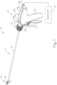
- FIG. 1 shows an exemplary ultrasonic surgical instrument (10). At least part of instrument (10) may be constructed and operable in accordance with at least some of the teachings of any of the various patents, patent application publications, and patent applications that are cited herein. As described therein and as will be described in greater detail below, instrument (10) is operable to cut tissue and seal or weld tissue (e.g., a blood vessel, etc.) substantially simultaneously.
- tissue and seal or weld tissue e.g., a blood vessel, etc.
- Instrument (10) of the present example comprises a handle assembly (12), a shaft assembly (14), and an end effector (16).
- Handle assembly (12) comprises a body (18) including a pistol grip (20) and a pair of buttons (22).
- Handle assembly (12) also includes a trigger (24) that is pivotable toward and away from pistol grip (20). It should be understood, however, that various other suitable configurations may be used, including but not limited to a scissor grip configuration.
- End effector (16) includes an ultrasonic blade (26) and a pivoting clamp arm (28).
- Clamp arm (28) is coupled with trigger (24) such that clamp arm (28) is pivotable toward ultrasonic blade (26) in response to pivoting of trigger (24) toward pistol grip (20); and such that clamp arm (28) is pivotable away from ultrasonic blade (26) in response to pivoting of trigger (24) away from pistol grip (20).
- clamp arm (28) may be coupled with trigger (24) will be apparent to those of ordinary skill in the art in view of the teachings herein.
- one or more resilient members are used to bias clamp arm (28) and/or trigger (24) to the open position shown in FIG. 1 .
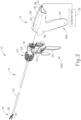
- instrument (10) of this example comprises a disposable assembly (29a) and a reusable assembly (29b) as illustrated in FIG. 2 in more detail.
- disposable assembly (29a) generally includes shaft assembly (14), end effector (16), buttons (22), trigger (24) and a portion of body (18).
- reusable assembly (29b) generally includes the remaining portion of body (18) with pistol grip (20) and an ultrasonic transducer assembly (30) (see FIG. 6A ).
- the distal portion of reusable assembly (29b) is configured to removably receive the proximal portion of disposable assembly (29a), as seen in FIGS. 1-2 , to form instrument (10).
- shaft assembly (14) and ultrasonic transducer assembly (30) are configured to removably couple together as will be discussed below in greater detail.
- Ultrasonic transducer assembly (30) is positioned within body (18) of handle assembly (12). Transducer assembly (30) is coupled with a generator (32) via a cable (34), such that transducer assembly (30) receives electrical power from generator (32) via cable (34). Piezoelectric elements in transducer assembly (30) convert electrical power from generator (32) into ultrasonic vibrations.
- Generator (32) may include a power source and control module that is configured to provide a power profile to transducer assembly (30) that is particularly suited for the generation of ultrasonic vibrations through transducer assembly (30).
- generator (32) may comprise a GEN04 or GEN1 1 sold by Ethicon Endo-Surgery, Inc. of Cincinnati, Ohio.
- generator (32) may be constructed in accordance with at least some of the teachings of U.S. Pub. No. 2011/0087212, entitled “Surgical Generator for Ultrasonic and Electrosurgical Devices,” published April 14, 2011 . It should also be understood that at least some of the functionality of generator (32) may be integrated into handle assembly (12), and that handle assembly (12) may even include a battery or other on-board power source such that cable (34) is omitted, while other cables may alternatively be used for electrically coupling various components. Still other suitable forms that generator (32) may take, as well as various features and operabilities that generator (32) may provide, will be apparent to those of ordinary skill in the art in view of the teachings herein.
- assemblies (29a, 29b) are coupled together to form instrument (10) and then is used to perform the surgical procedure. Assemblies (29a, 29b) are then decoupled from each other for further processing.
- disposable assembly (29a) is immediately disposed of while reusable assembly (29b) is sterilized and otherwise processed for re-use.
- reusable assembly (29b) may be sterilized in a conventional relatively low temperature, relatively low pressure, hydrogen peroxide sterilization process.
- reusable assembly (29b) may be sterilized using any other suitable systems and techniques.
- reusable assembly (29b) may be sterilized and reused approximately 100 times.
- reusable assembly (29b) may be subject to any other suitable life cycle.
- reusable assembly (29b) may be disposed of after a single use, if desired.
- disposable assembly (29a) is referred to herein as being "disposable,” it should be understood that, in some instances, disposable assembly (29a) may also be sterilized and otherwise processed for re-use.
- disposable assembly (29a) may be sterilized and reused approximately 2-30 times, using any suitable systems and techniques.
- disposable assembly (29a) may be subject to any other suitable life cycle.
- disposable assembly (29a) and/or reusable assembly (29b) includes one or more features that are operable to track usage of the corresponding assembly (29a, 29b), and selectively restrict operability of the corresponding assembly (29a, 29b) based on use.
- disposable assembly (29a) and/or reusable assembly (29b) may include one or more counting sensors and a control logic (e.g., microprocessor, etc.) that is in communication with the counting sensor(s).
- the counting sensor(s) may be able to detect the number of times instrument (10) is activated, the number of surgical procedures the corresponding assembly (29a, 29b) is used in, and/or any other suitable conditions associated with use.
- the control logic may track data from the counting sensor(s) and compare the data to one or more threshold values. When the control logic determines that one or more threshold values have been exceeded, the control logic may execute a control algorithm to disable operability of one or more components in the corresponding assembly (29a, 29b). In instances where the control logic stores two or more threshold values (e.g., a first threshold for number of activations and a second threshold for number of surgical procedures, etc.), the control logic may disable operability of one or more components in the corresponding assembly (29a, 29b) the first time one of those thresholds is exceeded, or on some other basis.
- two or more threshold values e.g., a first threshold for number of activations and a second threshold for number of surgical procedures, etc.
- a control logic may also determine whether instrument (10) is currently being used in a surgical procedure, and refrain from disabling instrument (10) until that particular surgical procedure is complete. In other words, the control logic may allow the operator to complete the current surgical procedure but prevent instrument (10) from being used in a subsequent surgical procedure.
- Various suitable forms that counters or other sensors may take will be apparent to those of ordinary skill in the art in view of the teachings herein.
- Various suitable forms that a control logic may take will also be apparent to those of ordinary skill in the art in view of the teachings herein.
- instrument (10) may simply omit features that track and/or restrict the amount of usage of instrument (10).
- Additional and/or alternative features with respect to alternative disposable and reusable assemblies (29a, 29b) may be constructed in accordance with at least some of the teachings of U.S. Pub. No. 2016/0015419, entitled “Ultrasonic Surgical Instrument with Removable Handle Assembly,” published January 21, 2016 .
- the instruments described herein is not intended to be limited to use with only replaceable or reusable components as described herein.
- end effector (16) of this example comprises clamp arm (28) and ultrasonic blade (26) as discussed briefly above.
- Clamp arm (28) includes a clamp pad (36), which faces blade (26).
- Clamp arm (28) is pivotable toward and away from blade (26) to selectively compress tissue between clamp pad (36) and blade (26).
- blade (26) is an integral feature of a distal end of an acoustic waveguide (38), which extends coaxially through tubes (40, 42), and which is configured to communicate ultrasonic vibrations to blade (26) as will be described in greater detail below.
- Shaft assembly (14) comprises an outer tube (40) and an inner tube (42).
- Outer tube (40) is operable to translate longitudinally relative to inner tube (42) to selectively pivot clamp arm (28) toward and away from blade (26).
- integral pin features (not shown) extending inwardly from respective projections (44) of clamp arm (28) pivotally secure a first portion of clamp arm (28) to a distally projecting tongue (46) of outer tube (40); while an inserted pin (48) pivotally secures a second portion of clamp arm (28) to a distally projecting tongue (50) of inner tube (42).
- tubes (40, 42) cooperate to pivot clamp arm (28) toward blade (26) when outer tube (40) is retracted proximally relative to inner tube (42).
- clamp arm (28) may be pivoted back away from blade (26) by translating outer tube (40) distally relative to inner tube (42).
- clamp arm (28) may be pivoted toward blade (26) to grasp, compress, seal, and sever tissue captured between clamp pad (36) and blade (26) as shown in FIG. 3A .
- Clamp arm (28) may also be pivoted away from blade (26), as shown in FIG. 3B , to release tissue from between clamp pad (36) and blade (26); and/or to perform blunt dissection of tissue engaging opposing outer surfaces of clamp arm (28) and blade (26).
- inner tube (42) translates while outer tube (40) remains stationary to provide pivotal movement of clamp arm (28).
- shaft assembly (14) of the present example extends distally from handle assembly (12).
- a rotation control assembly (52) has a rotation control member in the form of rotation control knob (54), which is secured to a proximal portion of outer tube (40).
- Knob (54) is rotatable relative to body (18), such that shaft assembly (14) is rotatable about the longitudinal axis defined by outer tube (40), relative to handle assembly (12).
- Such rotation may provide rotation of end effector (16) and shaft assembly (30) unitarily, which also includes unitary rotation of acoustic waveguide (38) coupled with transducer assembly (30) within handle assembly (12).
- various rotatable features may simply be omitted and/or replaced with alternative rotatable features, if desired.
- an articulation section (not shown) for deflecting end effector (16) at various lateral deflection angles relative to a longitudinal axis defined by outer tube (40).
- an articulation section may take a variety of forms.
- such an articulation section may be configured in accordance with one or more teachings of U.S. Pub. No. 2012/0078247, entitled "Articulation Joint Features for Articulation Surgical Device," published on March 29, 2012 .
- an articulation section may be configured in accordance with one or more teachings of U.S. Pub. No. 2014/0005701 and/or U.S. Pub. No. 2014/0114334 .
- Various other suitable forms that an articulation section may take will be apparent to those of ordinary skill in the art in view of the teachings herein.
- handle assembly (12) is reusable as discussed above and comprises body (18) defined by a pair of complementary housings (56) joined together. Housings (56) collectively define pistol grip (20) and include a cord support base (58) through which cable (34) extends between transducer assembly (30) and generator (32). While body (18) includes pistol grip (20) in this example, it should be understood that any other suitable kind of grip may be used.
- Waveguide (38) extends proximally through knob (54) and into body (18) to mechanically couple with transducer assembly (30).
- waveguide (38) is sufficiently coupled with transducer assembly (30)
- ultrasonic vibrations that are generated by transducer assembly (30) are communicated along waveguide (38) to reach blade (26).
- the distal end of blade (26) is located at a position corresponding to an anti-node associated with resonant ultrasonic vibrations communicated through waveguide (38), in order to tune the acoustic assembly to a preferred resonant frequency fo when the acoustic assembly is not loaded by tissue.
- transducer assembly (30) When transducer assembly (30) is energized, the distal end of blade (26) is configured to move longitudinally in the range of, for example, approximately 10 to 500 microns peak-to-peak, and in some instances in the range of about 20 to about 200 microns at a predetermined vibratory frequency f o of, for example, 55.5 kHz.
- f o a predetermined vibratory frequency
- the ultrasonic oscillation of blade (26) may simultaneously sever the tissue and denature the proteins in adjacent tissue cells, thereby providing a coagulative effect with relatively little thermal spread.
- an electrical current may also be provided through blade (26) and/or clamp pad (36) to also seal the tissue.
- waveguide (38) is threadably secured to transducer assembly (30) for acoustically coupling waveguide (38) with transducer assembly (30) for use.
- a predetermined torque is applied to waveguide (38) during installation with transducer assembly (30).
- a separate torque wrench (60) is used to couple the waveguide (38) with the transducer assembly (30) to inhibit overtightening of the waveguide (38).
- torque wrench (60) may ensure that a sufficient level of torque is used to couple waveguide (38) with transducer assembly (30) (i.e., to avoid separation of waveguide (38) from transducer assembly (30) while waveguide (38) and transducer assembly (30) are ultrasonically activated); while also preventing too much torque from being used to couple waveguide (38) with transducer assembly (30) (i.e., to avoid undue stress and the risk of breakage at the coupling of waveguide (38) from transducer assembly (30) while waveguide (38) and transducer assembly (30) are ultrasonically activated).
- Torque wrench (60) of the present example may be slid proximally along shaft assembly (14) until torque wrench (60) engages knob (54), such that rotating torque wrench (60) similarly rotates knob (54), thereby rotating shaft assembly (14).
- a proximal end portion of waveguide (38) is received within a threaded bore (62) (see FIG. 10A ) of transducer assembly (30).
- the operator rotates shaft assembly (14) via torque wrench (60), while holding handle assembly (12) stationary, thereby rotating waveguide (38) relative to transducer assembly (30).
- the proximal end portion of waveguide (38) is thus rotated into threaded engagement with transducer assembly (30).
- torque wrench (60) is configured to slip relative to knob (54) once the applied torque being transmitted therethrough exceeds the predetermined torque. In addition to slipping, torque wrench (60) generates audible and tactile "clicks" once the predetermined torque is achieved. Torque wrench (60) thus inhibits overtightening of waveguide (38) to transducer assembly (30).
- torque wrench (60) may be configured and operable in accordance with at least some of the teachings of U.S. Pub. No. 2007/0191713, entitled “Ultrasonic Device for Cutting and Coagulating,” published August 16, 2007 .
- Such engagement may make it difficult, or even impossible in some cases, for a user to apply the predetermined torque for proper coupling of the waveguide (38) to transducer assembly (30), because the user may not be able to apply a reactionary torque to transducer assembly (30) up to the predetermined torque.
- transducer assembly (30) may inhibit rotation of transducer assembly (30) relative to waveguide (38) during coupling such that the user can effectively rotate the waveguide (38) relative to transducer assembly (30) to thereby secure waveguide (38) with transducer assembly (30) with the predetermined torque. More particularly, it may be desirable to selectively seize rotation of transducer assembly (30) relative to body (18) such that waveguide (38) may be effectively coupled within transducer assembly (30).
- the following description relates to various exemplary transducer locks (110, 210, 310, 410, 510, 610, 710) for use respective with surgical instruments (112, 212, 312, 412, 512, 612, 712) discussed below in greater detail. Accordingly, like numbers described herein indicate like features with respect to each exemplary transducer lock (110, 210, 310, 410, 510, 610, 710).
- transducer locks (110, 210, 310, 410, 510, 610, 710) are configured to selectively inhibit, and even prevent rotation of transducer assembly (30) relative to body (18), it will be appreciated that some rotation in alternative examples is possible in accordance with the present disclosure.
- alternative transducer locks may not strictly prevent rotation, but at least inhibit rotation enough to provide a reactionary torque equal to at least the predetermined torque for proper installation. The present disclosure is thus not intended to be unnecessarily limited to preventing all relative rotation between transducer assembly (30) and body (18).
- FIGS. 5A-9 illustrate a first exemplary transducer lock, in the form of a longitudinal catch lock (110) of a surgical instrument (112).
- Longitudinal catch lock (110) includes a lock switch (114) extending through a lock channel (116) in body (18). More particularly, lock channel (116) extends longitudinally through an upper surface (118) of body (18) directly above the longitudinal axis.
- Lock switch (114) is thus translatable between a distal, unlocked position and a proximal, locked position for respectively unlocking and locking rotation of transducer assembly (30) relative to body (18).
- lock switch (114) and lock channel (116) are positioned on upper surface (118) of body (18) of the present example, it will be appreciated that lock switch (114) and lock channel (116) may be alternatively positioned so as to cooperate with transducer assembly (30).
- the present disclosure is thus not intended to be unnecessarily limited to having lock switch (114) and lock channel (116) positioned as shown herein.
- upper surface (118) further includes an unlocked indicia (120) and a locked indicia (122) for visually indicating a rotational state (i.e., unlocked state or locked state) of transducer assembly (30) to the user.
- the present example has unlocked indicia (120) positioned adjacent to a distal end of lock channel (116), whereas locked indicia (122) is positioned adjacent to a proximal end of lock channel (116).
- Unlocked indicia (120) more particularly includes an image of an unlocked padlock
- locked indicia (122) more particularly includes an image of a locked padlock.
- longitudinal catch lock (110) may also include one or more cooperating detents (not shown) to releasably secure lock switch (114) in either of the unlocked and locked positions. The user may then manipulate other portions of surgical instrument (112) without necessarily holding lock switch (114) in the locked position.
- lock switch (114) may be biased toward the unlocked position such that the user would hold lock switch (114) in the locked position while coupling with waveguide (38). The present disclosure is thus not intended to be unnecessarily limited to either secured or biased lock switch (114) positions.
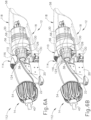
- longitudinal catch lock (110) further includes an arrester (124) operatively connected to lock switch (114) and an engagement feature (126) operatively connected to transducer assembly (30) that cooperate together to selectively allow or inhibit rotation of transducer assembly (30) relative to body (18).
- arrester (124) extends transversely downwardly from lock switch (114) toward the longitudinal axis and, in the unlocked position, is distally offset from engagement feature (126) and transducer assembly (30).
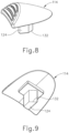
- Engagement feature (126) of the present example is particularly in the form of an engagement collar (126) having an annular collar body (128) and a plurality of teeth (130) positioned angularly about annular collar body (128).
- Each tooth (130) extends radially outwardly from annular collar body (128) such that any pair of teeth (130) is configured to receive at least a portion of arrester (124) therebetween.
- engagement collar (126) is rigidly secured to a distal end portion of transducer assembly (30) and positioned concentrically about the longitudinal axis. Engagement collar (126) is thus rotatably fixed relative to transducer assembly (30) such that each may either rotate together relative to body (18) or be rotatably secured together relative to body (18).
- FIGS. 6A and 7A illustrate lock switch (114) in the distal, unlocked position with arrester (124) in a distal, disengaged position, offset from engagement collar (126).
- Proximally translating lock switch (114) from the unlocked position toward the locked position similarly translates arrester (124) proximally from the disengaged position toward the engaged position shown in FIGS. 6B and 7B .
- arrester (124) aligns between teeth (130) such that arrester (124) effectively engages teeth (130) to seize rotation of engagement collar (126) relative to body (18).
- engagement collar (126) inhibits further rotation of transducer assembly (30) relative to body (18).
- arrester (124) has a drive cam surface (132), while each tooth (130) has a driven cam surface (134).
- Drive and driven cam surfaces (132, 134) cooperate such that drive cam surface (132), while moving toward the engaged position, urges drive cam surface (134) to slightly rotate engagement collar (126). Such slight rotation rotates one or more teeth (130) out of longitudinal alignment with arrester (124) in order to guide arrester (124) between teeth (130) to the engaged position.
- drive and driven cam surfaces (132, 134) are configured to properly align engagement collar (126) with arrester (124) and inhibit one or more teeth from essentially blocking the proximal movement of arrester (124) to the engaged position.
- shaft assembly (14) is initially uncoupled from transducer assembly (30).
- the user translates lock switch (114) proximally from the unlocked position to the locked position such that arrester (124) engages engagement collar (126) to seize rotation of transducer assembly (30) relative to body (18).
- the user then introduces the proximal end portion of waveguide (38) into threaded bore (62) and rotates knob (54) via torque wrench (60) in a tightening direction to threadably engage the proximal end portion of waveguide (38) with transducer assembly (30).
- torque wrench (60) in a tightening direction to threadably engage the proximal end portion of waveguide (38) with transducer assembly (30).
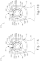
- FIGS. 10A-11B illustrate a second exemplary transducer lock, in the form of a transverse catch lock (210) of a surgical instrument (212).
- Transverse catch lock (210) includes a lock switch (214) extending through a lock channel (216) in body (18). More particularly, lock channel (216) extends transversely through an upper surface (118) of body (18) directly above the longitudinal axis.
- Lock switch (214) is thus transversely translatable between an upper, unlocked position and a lower, locked position for respectively unlocking and locking rotation of transducer assembly (30). Given that lock switch (214) is generally depressed in use so as to be transversely translatable, lock switch (214) may also be referred to herein as a lock button.
- lock switch (214) and lock channel (216) are positioned on upper surface (118) of body (18) of the present example, it will be appreciated that lock switch (214) and lock channel (216) may be alternatively positioned so as to cooperate with transducer assembly (30).
- the present disclosure is thus not intended to be unnecessarily limited to having lock switch (214) and lock channel (216) positioned as shown herein.
- transverse catch lock (210) includes a spring (220) that biases lock switch (214) toward the upper, unlocked position.
- Spring (220) is resiliently compressed between an upper mount (221) and a lower mount (222).
- Upper mount (221) is fixed to lock switch (214), whereas lower mount (222) is fixed to an interior of body (18).
- Spring (220) thus resiliently biases upper mount (221) and lock switch (214) upward such that upper mount (221) abuts against body (18). Depressing lock switch (214) downwardly toward the longitudinal axis causes lock switch (214) to translate downwardly through lower mount (222) to the locked position.
- the user may generally maintain depression of lock switch (214) to retain lock switch (214) in the locked position during coupling of waveguide (38) with transducer assembly (30).
- alternative examples may use various detents or other structures for releasably securing the position of lock switch (214) as desired.
- the present disclosure is thus not intended to be unnecessarily limited to either secured or biased lock switch (214) positions.
- transverse catch lock (210) further includes an arrester (224) operatively connected to lock switch (214) and engagement collar (126) operatively connected to transducer assembly (30) as discussed above.
- arrester (224) extends transversely downwardly from lock switch (214) toward the longitudinal axis and, in the unlocked position, is transversely offset from engagement collar (126) and transducer assembly (30).
- Arrester (224) includes a lower recess (225a) positioned between a pair of transversely extending catch members (225b).
- Catch members (225b) are configured to be positioned between respective pairs of teeth (130) of engagement collar (126), whereas lower recess (225a) is configured to receive a tooth (130) therein. Thereby, catch members (225b) are configured to capture tooth (130) within lower recess (225a).
- FIGS. 10A and 11A illustrate lock switch (214) in the upper, unlocked position with arrester (224) in an upper, disengaged position, offset from engagement collar (126).
- Proximally translating lock switch (214) from the unlocked position toward the locked position similarly translates arrester (224) downward from the disengaged position toward a lower, engaged position shown in FIGS. 10B and 11B .
- catch members (225b) of arrester (224) align between teeth (130) such that one tooth (130) is captured in lower recess (225a) to seize rotation of engagement collar (126) relative to body (18).
- engagement collar (126) inhibits further rotation of transducer assembly (30) relative to body (18).
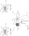
- FIGS. 12A-14B illustrate a third exemplary transducer lock, in the form of a bolt catch lock (310) of a surgical instrument (312).
- Bolt catch lock (310) includes a lock switch (314) extending through a lock channel (316) in body (18). More particularly, lock channel (316) extends longitudinally and laterally through an upper surface (118) of body (18). Lock switch (314) is thus pivotally and longitudinally translatable between a distal, unlocked position and a proximal, locked position for respectively unlocking and locking rotation of transducer assembly (30) as shown respectively in FIG 12A and 12B .
- lock switch (314) and lock channel (316) are positioned on upper surface (118) of body (18) of the present example, it will be appreciated that lock switch (314) and lock channel (216) may be alternatively positioned so as to cooperate with transducer assembly (30).
- the present disclosure is thus not intended to be unnecessarily limited to having lock switch (314) and lock channel (316) positioned as shown herein.
- the relative movement of lock switch (314) through lock channel (316) may also be referred to as a bolt action movement as illustrated with respect to FIGS. 12A-13B .
- lock channel (316) has a distal lateral slot (317a), an intermediate longitudinal slot (317b), and a proximal lateral slot (317c) through which to move lock switch (314) from the unlocked position to the locked position and vice versa.
- bolt catch lock (110) further includes an arrester (324) operatively connected to lock switch (314) and engagement collar (126) operatively connected to transducer assembly (30) as discussed above.
- arrester (324) extends transversely downwardly from lock switch (214) and has an annular body (325a) surrounding and concentrically positioned along the longitudinal axis. In the unlocked position, arrester (324) is distally offset from engagement collar (126) and transducer assembly (30).
- Arrester (324) further includes a plurality of catch members (325b) angularly positioned about the annular body (325a) and extending radially inwardly toward the longitudinal axis. Such catch members (325b) may also be referred to as inner teeth. Catch members (325b) are configured to be received between respective pairs of teeth (130) of engagement collar (126) for cooperative engagement therebetween in the locked position.
- Bolt catch lock (310) also includes a spring (320) shown in FIGS. 13A and 13B that biases lock switch (314) toward the distal, unlocked position.
- Spring (320) is resiliently compressed between an interior portion of body (18) and annular body (325a) of arrester (324). Spring (320) thus resiliently biases arrester (324) and lock switch (314) distally such that lock switch (314) is positioned distally in either distal slot (317a) of lock channel (316) or proximal slot (317c) of lock channel (316).
- each of distal and proximal slots (317a, 317c) has a distal detent (322) configured to receive lock switch (318) in the unlocked and locked positions.
- Each distal detent (322) thus releasably captures lock switch (318) to secure lock switch (318) without further grip by the user.
- the user may urge lock switch (318) from either distal detent (322) for bolt action movement as desired in the present example.
- Alternative examples may use various detents or other structures for simply biasing the position of lock switch (314) as desired. The present disclosure is thus not intended to be unnecessarily limited to either secured or biased lock switch (314) positions.
- FIGS. 12A , 13A , and 14A illustrate lock switch (314) in the distal, unlocked position with arrester (324) in a distal, disengaged position, offset from engagement collar (126).
- the user directs bolt catch lock (310) through bolt action movement between the unlocked and locked positions.
- pivoting lock switch (314) as shown in FIG. 14A pivots lock switch (314) from the locked position to a junction of the distal and intermediate slots (317a, 317b).
- arrester (324) pivots about longitudinal axis without translating longitudinally.
- lock switch (314) translates lock switch (314) proximally through intermediate slot to proximally direct catch members (325b) into engagement with teeth (130) of engagement collar (126) as shown in FIGS. 12B and 14B .
- lock switch (314) pivots through proximal slot (317c) to the locked position in distal detent (322) as shown in FIG. 13B , while arrester (324) pivots with engagement collar (126) in the engaged position as shown in FIG. 14B .
- Engagement collar (126) thereby inhibits further rotation of transducer assembly (30) relative to body by being captured rotatably within arrester (324).
- FIGS. 15A-15B illustrate a fourth exemplary transducer lock, in the form of a pivot catch lock (410) of a surgical instrument (412).
- Pivot catch lock (410) includes a pivotally mounted lock switch (414) extending through a lock channel (416) in body (18). More particularly, lock channel (416) extends transversely through an upper surface (118) of body (18) directly above the longitudinal axis.
- Lock switch (414) is thus pivotable between an upper, unlocked position and a lower, locked position for respectively unlocking and locking rotation of transducer assembly (30). Given that lock switch (414) is generally depressed in use so as to pivot toward the longitudinal axis, lock switch (414) may also be referred to herein as a lock button.
- lock switch (414) and lock channel (416) are positioned on upper surface (118) of body (18) of the present example, it will be appreciated that lock switch (414) and lock channel (416) may be alternatively positioned so as to cooperate with transducer assembly (30).
- the present disclosure is thus not intended to be unnecessarily limited to having lock switch (414) and lock channel (416) positioned as shown herein.
- pivot catch lock (410) includes a spring (420) that biases lock switch (414) toward the upper, unlocked position.
- spring (420) is a torsional spring resiliently compressed between lock switch (414) and an interior of body (18). Spring (420) thus resiliently biases lock switch (414) upwardly such that an interior portion of lock switch (414) abuts against body (18). Depressing lock switch (414) downwardly toward the longitudinal axis causes lock switch (414) to pivot downwardly to the locked position.
- the user may generally maintain depression of lock switch (414) to retain lock switch (414) in the locked position during coupling of waveguide (38) with transducer assembly (30).
- Pivot catch lock (110) further includes an arrester (424) operatively connected to lock switch (414) and engagement collar (126) operatively connected to transducer assembly (30) as discussed above.
- arrester (424) extends transversely downward from lock switch (414) toward the longitudinal axis and, in the unlocked position, is transversely offset from engagement collar (126) and transducer assembly (30).
- a lower end portion of arrester (424) is configured to be positioned between respective pairs of teeth (130) of engagement collar (126), thereby inhibiting relative movement therebetween.
- FIG. 15A illustrates lock switch (414) in the upper, unlocked position with arrester (424) in an upper, disengaged position, offset from engagement collar (126). Pivoting lock switch (414) downwardly from the unlocked position toward the locked position similarly translates arrester (424) downwardly from the disengaged position toward a lower, engaged position shown in FIG. 15B .
- the lower end portion of arrester (424) aligns between teeth (130) to engage at least one tooth (130) and seize rotation of engagement collar (126) relative to body (18).
- engagement collar (126) inhibits further rotation of transducer assembly (30) relative to body (18).
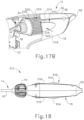
- FIGS. 16-19B illustrate a fifth exemplary transducer lock, in the form of a grip clamp lock (510) of a surgical instrument (512).
- Grip clamp lock (510) includes a pair of lock switches (514) extending respectively through a pair of lock channels (516) in body (18). More particularly, lock channels (516) extend laterally through opposing side surfaces (518) of body (18) directly lateral from the longitudinal axis.
- Each lock switch (514) is thus translatable between an outer, unlocked position and an inner, locked position for respectively unlocking and locking rotation of transducer assembly (30) relative to body (18).
- each lock switch (514) is configured to be directed inwardly toward the longitudinal axis from the unlocked position to the locked position as shown in FIGS.
- lock switches (514) may also be referred to herein as lock buttons. While each lock switch (514) and lock channels (516) are positioned on side surfaces (518) of body (18) of the present example, it will be appreciated that lock switches (514) and lock channels (516) may be alternatively positioned so as to cooperate with transducer assembly (30). Furthermore, while the present example of grip clamp lock (510) has two lock switches (514), it will be appreciated that fewer or more such switches (514) may be used in alternative examples. The present disclosure is thus not intended to be unnecessarily limited to having two lock switches (514) and two lock channels (516) positioned as shown herein.
- Each lock switch (514) is resiliently mounted in lock channels (516) by a biasing member (not shown), which urges each lock switch (514) toward the unlocked position.
- the user may generally maintain depression of each lock switch (514) to retain lock switches (514) in the locked position during coupling of waveguide (38) with transducer assembly (30).
- the user may use one or more hands to selectively squeeze lock switches (514) simultaneously toward the locked position as shown in FIGS. 18-19B .
- alternative examples may use various detents or other structures for releasably securing the position of lock switches (514) as desired.
- the present disclosure is thus not intended to be unnecessarily limited to either secured or biased lock switch (514) positions.
- Grip clamp lock (510) further includes an arrester (524) operatively connected to lock switch (514) and an engagement feature (526) operatively connected to transducer assembly (30) that cooperate together to selectively allow or inhibit rotation of transducer assembly (30) relative to body (18).
- each arrester (524) extends laterally inwardly from each respective lock switch (514) toward the longitudinal axis and, in the unlocked position is laterally offset from engagement feature (526) and transducer assembly (30).
- arrester (524) includes an abrasive, high-friction surface, such as a serrated surface (525). Serrated surface (525) faces inwardly toward longitudinal axis for engagement with engagement feature (526) as shown in FIGS. 19A and 19B .
- engagement feature (526) of the present example is particularly in the form of another serrated surface (528) rigidly fixed on a transducer housing (529) of transducer assembly (30).
- Serrated surface (528) generally covers an outer surface of transducer housing (529) such that serrated surface (528) surrounds the longitudinal axis.
- Serrated surface (528) also extends radially outwardly from the outer surface of transducer housing (529) for engagement with serrated surfaces (525) of each arrester (524). Engagement between serrated surfaces (525) of arresters (524) and serrated surface (528) of transducer housing (529) tends to inhibit relative rotation with a relatively high coefficient of friction therebetween.
- each lock switch (514) increases the compression force of serrated surfaces (525) of arresters (524) against serrated surface (528) of transducer housing (529) for increased friction.
- the user may thus apply more or less compression as desired for inhibiting rotation of transducer assembly (30).
- the present example includes various serrated surfaces (525) for inhibiting relative rotation, it will be appreciated that alternative high-friction surfaces may also be so used.
- alternative structures extending respectively from arrester (524) and transducer housing (529) that cooperatively engage for inhibiting relative rotation may also be similarly configured. Accordingly, other structures for such engagement may be used with grip clamp lock (510), and the present disclosure is not intended to be unnecessarily limited to the abrasive, high-friction, serrated surfaces (525, 528) described herein.
- FIGS. 17A and 19A illustrate lock switches (514) in the laterally outward, unlocked position with arrester (524) in a laterally outward, disengaged position, which is offset from serrated surface (528) of transducer housing (529).
- Laterally translating lock switches (514) inwardly from the unlocked position toward the locked position similarly translates arrester (524) inward from the disengaged position toward an engaged position shown in FIGS. 17B and 19B .
- serrated surfaces (525) of arresters (524) frictionally engage serrated surface (528) to seize rotation of transducer housing (629) relative to body (18) for inhibiting rotation of transducer assembly (30).
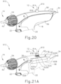
- FIGS. 20-21B illustrate a sixth exemplary transducer lock, in the form of a translational flat clamp lock (610) of a surgical instrument (612).
- Translational flat clamp lock (610) includes a lock switch (614) extending through a lock channel (616) in body (18). More particularly, lock channel (616) extends transversely through upper surface (118) of body (18) directly above the longitudinal axis.
- Lock switch (614) is thus translatable between an upper, unlocked position and a lower, locked position for respectively unlocking and locking rotation of transducer assembly (30) relative to body (18).
- lock switch (614) is configured to be directed inwardly toward the longitudinal axis from the unlocked position to the locked position.
- lock switch (614) is generally depressed in use so as to be translate toward the longitudinal axis
- lock switch (614) may also be referred to herein as a lock button. While lock switch (614) and lock channel (616) are positioned on upper surface (118) of body (18) of the present example, it will be appreciated that lock switch (614) and lock channel (616) may be alternatively positioned so as to cooperate with transducer assembly (30).
- Lock switch (614) is resiliently mounted in lock channels (516) by a pair of biasing members (617), which urge lock switch (614) toward the unlocked position.
- the user may generally maintain depression of lock switch (614) to retain lock switches (614) in the locked position during coupling of waveguide (38) with transducer assembly (30).
- the user may use one or more hands to selectively depress lock switch (614) toward the locked position as shown in FIG. 21B .
- alternative examples may use various detents or other structures for releasably securing the position of lock switch (614) as desired.
- the present disclosure is thus not intended to be unnecessarily limited to either secured or biased lock switch (614) positions.
- Translational flat clamp lock (610) further includes an arrester (624) operatively connected to lock switch (614) and an engagement feature (626) operatively connected to transducer assembly (30) that cooperate together to selectively allow or inhibit rotation of transducer assembly (30) relative to body (18).
- arrester (624) extends transversely inwardly from lock switch (614) toward the longitudinal axis and, in the unlocked position is transversely offset from engagement feature (626) and transducer assembly (30).
- arrester (624) extends downwardly from lock switch (614) to a lower end portion (625a) having a flat (625b).
- Flat (625b) faces inwardly toward longitudinal axis for engagement with engagement feature (626) as shown in FIGS. 21A and 21B .
- Engagement feature (626) of the present example includes a plurality of flats (628) extending along a transducer housing (629) of transducer assembly (30). More particularly, six flats (628) extend along transducer housing (629) such that a transverse cross-section of transducer housing (629) defines a hexagonal shape about the longitudinal axis. Each flat (628) extends in the longitudinal direction so as to be parallel with the longitudinal axis and, when rotated to the uppermost position about the longitudinal axis, is parallel with flat (625b) on lower end portion (625a) of arrester (624). Thus, regardless of the rotatable position of transducer housing (629) at least one flat (628) is positioned to receive flat (625b) of arrester thereagainst for engagement.
- FIGS. 20 and 21A illustrate lock switches (614) in the upper, unlocked position with arrester (624) in an upper, disengaged position, which is offset from flat (628) of transducer housing (629).
- Transversely translating lock switch (614) downwardly from the unlocked position toward the locked position similarly translates arrester (624) downwardly from the disengaged position toward an engaged position shown in FIG. 21B .
- flat (625b) of arrester (624) engages one of flats (628) to seize rotation of transducer housing (629) relative to body (18) for inhibiting rotation of transducer assembly (30).
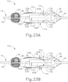
- FIGS. 22-23B illustrate a seventh exemplary transducer lock, in the form of a pivot flat clamp lock (710) of a surgical instrument (712).
- Pivot flat clamp lock (710) includes a pair of lock switches (714) extending respectively through a pair of lock channels (716) in body (18). More particularly, each lock switch (714) is a portion of body (18) having lock channel (716) generally surrounding lock switch (714), but connected to a remainder of body (18) by a living hinge (715). Each lock switch (714) is thus pivotable about living hinge (715) between an outer, unlocked position and an inner, locked position for respectively unlocking and locking rotation of transducer assembly (30) relative to body (18).
- each lock switch (714) is configured to be directed inwardly toward the longitudinal axis from the unlocked position to the locked position as shown in FIGS. 23A and 23B , respectively.
- lock switches (714) may also be referred to herein as lock buttons. While each lock switch (714) and lock channel (716) are positioned on side surfaces (518) of body (18) of the present example, it will be appreciated that lock switches (714) and lock channels (716) may be alternatively positioned so as to cooperate with transducer assembly (30).
- pivot flat clamp lock (710) has two lock switches (714), it will be appreciated that fewer or more such switches (714) may be used in alternative examples.
- the present disclosure is thus not intended to be unnecessarily limited to having two lock switches (714) and two lock channels (716) positioned as shown herein.
- Each lock switch (714) is resiliently mounted in lock channels (716) via living hinge (715).
- the user may generally maintain depression of each lock switch (714) to retain lock switches (714) in the locked position during coupling of waveguide (38) with transducer assembly (30).
- the user may use one or more hands to selectively squeeze lock switches (714) simultaneously toward the locked position.
- alternative examples may use various detents or other structures for releasably securing the position of lock switches (714) as desired.
- the present disclosure is thus not intended to be unnecessarily limited to either secured or biased lock switch (714) positions.
- Pivot flat clamp lock (710) further includes an arrester (724) operatively connected to lock switch (714) and the plurality of flats (628) along transducer housing (629) that cooperate together to selectively allow or inhibit rotation of transducer assembly (30) relative to body (18).
- each arrester (724) includes an inner flat (725) of lock switch (714) that extends transversely along an interior of each respective lock switch (714) and, in the unlocked position, is laterally offset from flats (628) of transducer housing (629).
- Flat (725) faces inwardly toward the longitudinal axis for engagement with flats (628) as shown in FIGS. 23A and 23B .
- FIGS. 22 and 23A illustrate lock switches (714) in the laterally outward, unlocked position with arrester (524) in a laterally outward, disengaged position, which is offset from flats (628) of transducer housing (629).
- Laterally pivoting lock switches (714) inwardly from the unlocked position toward the locked position similarly pivots arrester (724) inward from the disengaged position toward an engaged position shown in FIG. 23B .
- flats (725) of arresters (724) engage respective flats (628) to seize rotation of transducer housing (629) relative to body (18) for inhibiting rotation of transducer assembly (30).
- waveguide (38) is rotatably coupled with transducer assembly (30) to the predetermined torque with torque wrench (60) for each of surgical instruments (10, 112, 212, 312, 412, 512, 612, 712).
- torque wrench (60) is separable from surgical instruments (10, 112, 212, 312, 412, 512, 612, 712), such that torque wrench (60) is applied to shaft assembly (14) for coupling waveguide (38) to transducer assembly (30) and then removed from shaft assembly (14) following tightening of waveguide (38) to the predetermined torque so that each surgical instrument (10, 112, 212, 312, 412, 512, 612, 712) may then be used to perform the surgical procedure.
- handling and manipulating torque wrench (60) separately from surgical instruments (10, 112, 212, 312, 412, 512, 612, 712) may add further complexity to the surgical procedure and may be difficult to manage in some instances.
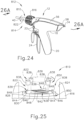
- Integral torque wrench (810) is incorporated into a surgical instrument (812) described below in additional detail and illustrated in FIGS. 24-26B .
- Integral torque wrench (810) is incorporated into a shaft assembly (814) and remains connected with knob (816) prior to coupling waveguide (38) with transducer assembly (30) and after coupling waveguide (38) with transducer assembly (30).
- Integral torque wrench (810) may thus be manipulated as desired for coupling waveguide (38) with transducer assembly (30) at the predetermined torque while also allowing for manipulation of shaft assembly (814) as described above with respect to shaft assembly (14). While integral torque wrench (810) is shown incorporated into shaft assembly (814) and connected to knob (816), it will be appreciated that alternative arrangements for limiting torque to waveguide (38) may also be provided. The present disclosure is thus not intended to be unnecessarily limited to the specific arrangement of integral torque wrench (810) with knob (816) as shown herein. Furthermore, like numbers provided below indicate like features described above in additional detail. It should also be understood that integral torque wrench (810) may be used in combination with any of the transducer assembly (30) arresting components described above. In other words, integral torque wrench (810) may be readily incorporated into any of surgical instruments (10, 112, 212, 312, 412, 512, 612, 712) described above.
- surgical instrument (812) has shaft assembly (814) with integral torque wrench (810) connected to knob (816).
- Integral torque wrench (810) receives outer tube (40) through a bore (818) and is selectively rotatable about the longitudinal axis on outer tube (40).
- Integral torque wrench (810) releasably connects to knob (816) to transmit torque from integral torque wrench (810) to knob (816) via a releasable coupling (820).
- Releasable coupling (820) transmits torque in a rotatable, tightening direction up to the predetermined torque at which waveguide (38) operatively couples with transducer assembly (30).
- releasable coupling (820) is configured to release knob (816) as the transmitted torque exceeds the predetermined torque.
- integral torque wrench (810) rotatably slips relative to knob (816) for inhibiting overtightening of waveguide (38) (see FIG. 26A ) with transducer assembly (30).
- torque wrench (810) may emit audible and/or tactile "clicks" when torque wrench (810) rotatably slips relative to knob (816).
- integral torque wrench (810) includes a cylindrical body (822) extending coaxially along the longitudinal axis, such that cylindrical body (822) is positioned concentrically about the longitudinal axis.
- a proximal end portion of cylindrical body (822) includes a portion of releasable coupling (820), whereas a distal end portion of knob (816) includes a remaining portion of releasable coupling (820).
- These opposing portions of releasable coupling (820) cooperatively engage such that rotating integral torque wrench (810) simultaneously rotates knob (816) and cooperatively disengages to allow for relative slip for limiting torque transferred therebetween.
- the proximal end portion of cylindrical body (822) is axially fixed to the distal end portion of knob (816) while allowing cylindrical body (822) to rotate relative to knob (816) during slip.
- the distal end of knob (816) includes a cylindrical distal opening (824) extending coaxially along the longitudinal axis that rotatably receives the proximal end portion of cylindrical body (822).
- An annular pedestal (826) extends distally toward cylindrical body (822) from an inner face (828) of knob (816) to define an annular securement channel (830) therebetween.
- annular securement lip (832) extends radially inwardly from the proximal end portion of cylindrical body (822) and is configured to be received within annular securement channel (830) to axially fix integral torque wrench (810) to knob (816).
- annular pedestal (826), annular securement channel (830), and annular securement lip (832) is coaxial with each other and the longitudinal axis.
- Annular securement lip (832) of integral torque wrench (810) is thus captured in the longitudinal direction within annular securement channel (830) between annular pedestal (826) and inner face (828), but configured for relative rotation in securement channel (830) during slip as discussed below in greater detail.
- Annular securement lip (832) surrounds a cylindrical proximal opening (834) into cylindrical body (822) that also extends distally and coaxially along the longitudinal axis.
- Proximal opening (834) into cylindrical body (822) receives annular pedestal (826) for cooperative engagement and disengagement therebetween.
- annular pedestal (826) has at least one compressible member (838) extending proximally toward annular pedestal (826).
- annular pedestal (826) has at least one cam (840) extending distally toward inner face (836) for engagement with compressible member (838).
- inner face (836) and annular pedestal (826) respectively have four such compressible members (838) and four such cams (840).
- Compressible members (838) and cams (840) are positioned angularly about inner face (836) and annular pedestal (826), respectively, and positioned such that each compressible member (838) cooperates with one respective cam (840).
- Each cam (840) more particularly includes a cam ramp (842) that extends along a radial arc about the longitudinal axis from an initial end (844) to a terminal end (846).
- a ramp surface (848) of cam ramp (842) at initial end (844) is essentially flush with a distal surface of annular pedestal (826), but projects distally away from the distal surface of annular pedestal (826) toward terminal end (846). In other words, a longitudinal depth of cam ramp (842) increases from initial end (844) to terminal end (846).
- Compressible member (838) is generally configured to compress in a distal direction from an elongated state to a compressed state and resiliently return from the compressed state to the elongated state. In the elongated state, compressible member (838) initially compresses in the distal direction with the application of a relatively small distal force. However, as compressible member (838) compresses toward the compressed state, the applied distal force increases to cause similar compression. In other words, as compression increases, the amount of applied distal force must also increase to continue further compression.
- Each compressible member (838) is generally engaged with annular pedestal (826), because cylindrical body (822) is axially fixed relative to knob (816) as discussed above. At a minimum torque, each compressible member (838) frictionally engages initial end (844) of ramp surface (848) as shown in FIGS. 25 and 26A in the elongated state. Selectively rotating cylindrical body (822) in a tightening direction (850) similarly rotates each compressible member (838) about the longitudinal axis. In turn, the collective frictional engagement between compressible members (838) and ramp surfaces (848) causes annular pedestal (826) and knob (816) to also rotate in tightening direction (850). Such minimum torque may be sufficient for threading an initial portion of waveguide (38) into transducer assembly (30).
- 26B shows compressible member being compressed in the distal direction, as indicated by arrow (852), while being rotated in tightening direction (850).
- annular pedestal (826) is effectively in compression between compressible members (838) and annular securement lip (832) as torque increases toward the predetermined torque for operatively coupling waveguide (38) with transducer assembly (30).
- integral torque wrench (810) is configured to apply torque at the predetermined torque to complete the coupling of waveguide (38) to transducer assembly (30). Just as the coupling torque between waveguide (38) and transducer assembly (30) increases beyond the predetermined torque, cam ramps (838) further slip relative to compressible members (838). Thus, each compressible member (838) slips off of terminal end (846) of cam ramp (842) and lands adjacent to another initial end (844) of a neighboring cam ramp (842) to limit the application of additional torque beyond the predetermined torque.
- integral torque wrench (810) in tightening direction (850) is possible by the user, but, since frictional engagement between compressible members (838) and cam ramps (842) is limited to the predetermined torque transmission, further rotation will simply result in continual slip between integral torque wrench (810) and knob (816).
- slippage of compressible member (838) relative to cam ramp (842) may also generate an audible indicator (e.g., a "click"), a tactile indicator, or other signal to the user that waveguide (38) is coupled with transducer assembly (30) at the predetermined torque.
- Integral torque wrench (810) may thus also be one example of an integral torque indicator.
- integral torque wrench (810) provides various releasable coupling features on each of cylindrical body (822) and knob (816).
- cylindrical body (822) and knob (816) may be possible in accordance with the invention.
- compressible members (838) and cams (840) may be positioned on either one of cylindrical body (822) and knob (816) for respective cooperation as discussed herein.
- alternative compressible members and cams for guiding compression and frictional engagement may be used. The invention is thus not intended to be unnecessarily limited to the particular compressible members (838) and cams (840) described herein.
- the user if the user continues to rotate waveguide (38) after operative coupling, the user is needlessly extending the time for installation.
- waveguide (38) and transducer assembly (30) may function improperly .
- these decisions may extend surgical procedure. At worst, these decisions may damage any one of surgical instruments (10, 112, 212, 312, 412, 512, 612, 712, 812) and/or reduce the likelihood of a positive outcome for the patient.
- an integral torque indicator into one or more portions of surgical instruments (10, 112, 212, 312, 412, 512, 612, 712, 812) for communicating a signal to the user that waveguide (38) has been coupled with transducer assembly (30) at the predetermined torque.
- One such integral torque indicator (910) is incorporated into a surgical instrument (912) described below in additional detail and illustrated in FIGS. 27-31 .
- portions of integral torque indicator (910) are incorporated into a shaft assembly (914) and a transducer assembly (926).
- portions of integral torque indicator (910) are incorporated into a shaft assembly (914) and a transducer assembly (926).
- portions of integral torque indicator (910) are incorporated into a shaft assembly (914) and a transducer assembly (926).
- portions of integral torque indicator (910) may be alternatively positioned so as to cooperate together to generate the signal.
- the present disclosure is thus not intended to be unnecessarily limited to the specific arrangement of integral torque indicator (910) as shown herein.
- surgical instrument (912) includes a distal portion (918), an intermediate portion (920), and a proximal portion (922).
- Distal portion (918) has shaft assembly (914) with knob (54) and waveguide (38), end effector (16) (see FIG. 1 ), buttons (22), trigger (24) and a portion of a body (924).
- Intermediate portion (920) has another portion of body (924) with pistol grip (20).
- Proximal portion (922) generally includes transducer assembly (926) contained with a cover (928) for storage and protection. Accordingly, cover (928) may also be considered a remaining portion of body (924) of surgical instrument (912).
- distal, intermediate, and proximal portions (918, 920, 922) of surgical instrument (912) may be disposable and/or reusable as discussed above with respect to surgical instrument (10) (see FIG. 1 ).
- distal portion (918) is disposable, whereas intermediate and proximal portions (920, 922) are reusable.
- distal portion (918) also includes a keyed clip member (929) configured to be received within an alignment hole (not shown) in intermediate portion (920).
- Intermediate portion (920) includes a release switch (930) that releasably connects with keyed clip member (929) for at least partially mechanically coupling distal and intermediate portions of body (18).
- Intermediate portion (920) of body (18) further includes an electrical connector (931) received within distal portion (918) of body (18) for electrically coupling intermediate and distal portions (920, 918) of surgical instrument (912).
- Proximal portion (922) of surgical instrument (912) includes grip clamp lock (510) having lock switch (514) extending through cover (928) for seizing rotation of transducer assembly (926) relative to cover (928).
- Body (18) of intermediate portion (920) also includes a pair of additional lock channels (516) configured to respectively receive lock switches (514) as transducer assembly (926) is removably received within intermediate portion (920) of body (18). The user may thus access lock switch (514) and squeeze lock switches (514) as shown in FIG. 29 for inhibiting rotation of transducer assembly (926) during coupling of waveguide (38) with transducer assembly (926) as discussed above.
- FIGS. 30A-30C show integral torque indicator (910) communicating the audible and tactile signal upon coupling waveguide (38) with transducer assembly (926).
- waveguide (38) has a threaded hole (932) coaxially positioned within waveguide (38), whereas transducer assembly (926) has a threaded stud (934) configured to be threadably received within threaded hole (932) for coupling.
- Transducer assembly (926) further includes a resilient stop, such as a resilient o-ring (936), which is positioned about a proximal end of threaded stud (934) against transducer assembly (926).
- Resilient o-ring is configured to provide additional resilience within the threaded joint of threaded hole (932) and threaded stud (934) at the predetermined torque for inhibiting waveguide (38) from inadvertently loosening during use.
- Integral torque indicator (910) includes a pair of offset fin members (938) configured to cooperatively engage a pick tab (940) for generating the audible and tactile signal. More particularly, fin members (938) extend radially from a proximal portion of waveguide (38) and are positioned angularly relative to each other to define a space (942) therebetween. Each fin member (938) is adjacent to a proximal face (944) of waveguide (38) for engagement with pick tab (940) during coupling of waveguide (38) with threaded stud (934).
- Pick tab (940) longitudinally extends from transducer assembly (926) above the longitudinal axis and over o-ring (935) in the distal direction. Pick tab (940) is generally rigid, whereas fin members (938) are relatively resilient and configured to audibly and tactilely resonate when plucked.
- fin members (938) rotate about the longitudinal axis while being drawn proximally toward pick tab (940). Fin members (938) and pick tab (940) are positioned relative to each other such that as the torque reaches the predetermined torque shown in FIG. 30C , pick tab (940) sequentially plucks fin members (938). The second pluck of fin members (938) generates the second signal to effectively communicate to the user that the waveguide (38) and transducer assembly (926) are operatively coupled with the predetermined torque as shown in FIG. 31 .
- any number of signals may be tuned to the predetermined torque and the present disclosure is not intended to be unnecessarily limited to two such signals. It will be further appreciated that any such signal, audible and/or tactile may be so used, and the present disclosure is not intended to be unnecessarily limited to the particular signals described herein.
- any of the versions of instruments described herein may include various other features in addition to or in lieu of those described above.
- any of the instruments described herein may also include one or more of the various features disclosed in any of the various references.
- teachings herein may be readily applied to any of the instruments described in any of the other references cited herein, such that the teachings herein may be readily combined with the teachings of any of the references cited herein in numerous ways.
- teachings herein may be readily applied to electrosurgical instruments, stapling instruments, and other kinds of surgical instruments.
- Other types of instruments into which the teachings herein may be incorporated will be apparent to those of ordinary skill in the art.
- Versions of the devices described above may have application in conventional medical treatments and procedures conducted by a medical professional, as well as application in robotic-assisted medical treatments and procedures.
- various teachings herein may be readily incorporated into a robotic surgical system such as the DAVINCI TM system by Intuitive Surgical, Inc., of Sunnyvale, California.
- DAVINCI TM system by Intuitive Surgical, Inc., of Sunnyvale, California.
- teachings herein may be readily combined with various teachings of U.S. Pat. No. 6,783,524, entitled "Robotic Surgical Tool with Ultrasound Cauterizing and Cutting Instrument," published August 31, 2004 .
- Versions described above may be designed to be disposed of after a single use, or they can be designed to be used multiple times. Versions may, in either or both cases, be reconditioned for reuse after at least one use. Reconditioning may include any combination of the steps of disassembly of the device, followed by cleaning or replacement of particular pieces, and subsequent reassembly. In particular, some versions of the device may be disassembled, and any number of the particular pieces or parts of the device may be selectively replaced or removed in any combination. Upon cleaning and/or replacement of particular parts, some versions of the device may be reassembled for subsequent use either at a reconditioning facility, or by a user immediately prior to a procedure.
- reconditioning of a device may utilize a variety of techniques for disassembly, cleaning/replacement, and reassembly. Use of such techniques, and the resulting reconditioned device, are all within the scope of the present disclosure.
- versions described herein may be sterilized before and/or after a procedure.
- the device is placed in a closed and sealed container, such as a plastic or TYVEK ® bag.
- the container and device may then be placed in a field of radiation that can penetrate the container, such as gamma radiation, x-rays, or high-energy electrons.
- the radiation may kill bacteria on the device and in the container.
- the sterilized device may then be stored in the sterile container for later use.
- a device may also be sterilized using any other technique known in the art, including but not limited to beta or gamma radiation, ethylene oxide, or steam.
Landscapes
- Health & Medical Sciences (AREA)
- Life Sciences & Earth Sciences (AREA)
- Surgery (AREA)
- Engineering & Computer Science (AREA)
- General Health & Medical Sciences (AREA)
- Veterinary Medicine (AREA)
- Nuclear Medicine, Radiotherapy & Molecular Imaging (AREA)
- Biomedical Technology (AREA)
- Public Health (AREA)
- Animal Behavior & Ethology (AREA)
- Molecular Biology (AREA)
- Medical Informatics (AREA)
- Heart & Thoracic Surgery (AREA)
- Mechanical Engineering (AREA)
- Dentistry (AREA)
- Otolaryngology (AREA)
- Physics & Mathematics (AREA)
- Plasma & Fusion (AREA)
- Radiology & Medical Imaging (AREA)
- Pathology (AREA)
- Oral & Maxillofacial Surgery (AREA)
- Optics & Photonics (AREA)
- Biophysics (AREA)
- Surgical Instruments (AREA)
- Apparatuses For Generation Of Mechanical Vibrations (AREA)
Claims (3)
- Chirurgisches Instrument, umfassend:(a) einen Endeffektor (16),(b) eine sich proximal von dem Endeffektor (16) entlang einer Längsachse erstreckende Schaftanordnung (814), wobei die Schaftanordnung (814) Folgendes aufweist:(i) einen akustischen Wellenleiter (38), der sich entlang der Längsachse erstreck,(ii) einen mit dem akustischen Wellenleiter (38) wirkverbundenen Knopf (816), wobei der Knopf (816) dazu ausgestaltet ist, gezielt gedreht zu werden und dadurch den akustischen Wellenleiter (38) zu drehen, und(c) einen integralen Drehmomentschlüssel (810), der innen in dem Knopf (816) positioniert und über eine freigebbare Koppelung (820) mit dem Knopf (816) verbunden ist, so dass der integrale Drehmomentschlüssel (810) zum Drehen mit dem Knopf (816) ausgestaltet ist, wobei der integrale Drehmomentschlüssel (810) einen Körper (822), ein zusammendrückbares Glied (838), das dazu ausgestaltet ist, in einer distalen Richtung aus einem langgestreckten Zustand in einen zusammengedrückten Zustand zusammengedrückt zu werden, und einen Nocken (840) umfasst, wobei sich das zusammendrückbare Glied (838) oder der Nocken (840) von dem Körper (822) erstreckt und sich das/der jeweils andere des zusammendrückbaren Glieds (838) und des Nockens (840) von dem Knopf (816) erstreckt, wobei die freigebbare Koppelung (820) dazu ausgestaltet ist, Drehmoment bis zu einem vorbestimmten Drehmoment von dem integralen Drehmomentschlüssel (810) an den Knopf (816) zu übertragen, wobei das zusammendrückbare Glied (838) mit dem Nocken (840) in Eingriff steht, um dadurch Drehmoment zu übertragen, wobei der Nocken (840) dazu ausgestaltet ist, das zusammendrückbare Glied (838) zusammenzudrücken, wenn das dort hindurch übertragene Drehmoment erhöht wird, und wobei die freigebbare Koppelung (820) dazu ausgestaltet ist, den Knopf (816) freizugeben, wenn das übertragene Drehmoment das vorbestimmte Drehmoment übersteigt, wobei das zusammendrückbare Glied (838) dazu ausgestaltet ist, von dem Nocken (840) zu rutschen, um das zusammendrückbare Glied (838) aus dem Nocken (840) auszurücken, wenn das dort hindurch übertragene Drehmoment das vorbestimmte Drehmoment übersteigt, so dass der integrale Drehmomentschlüssel (810) drehungsmäßig bezüglich des Knopfs (816) rutscht, um zu verhindern, dass die Übertragung von Drehmoment durch den Knopf (816) das vorbestimmte Drehmoment übersteigt, während der akustische Wellenleiter (38) an eine Ultraschallwandleranordnung gekoppelt wird.
- Chirurgisches Instrument nach Anspruch 1, ferner umfassend:(a) einen Instrumentenkörper und(b) eine Ultraschallwandleranordnung, die drehbar in dem Instrumentenkörper montiert ist, dass die Ultraschallwandleranordnung dazu ausgestaltet ist, sich gezielt um die Längsachse zu drehen, wobei die Ultraschallwandleranordnung zur drehbaren Koppelung mit mit dem akustischen Wellenleiter ausgestaltet ist.
- Chirurgisches Instrument nach Anspruch 1, wobei sich der integrale Drehmomentschlüssel konzentrisch entlang der Längsachse erstreckt und zum Drehen um die Längsachse ausgestaltet ist.
Applications Claiming Priority (4)
| Application Number | Priority Date | Filing Date | Title |
|---|---|---|---|
| US15/378,452 US10646300B2 (en) | 2016-12-14 | 2016-12-14 | Ultrasonic surgical instrument with transducer locking feature |
| EP20182916.5A EP3777725B1 (de) | 2016-12-14 | 2017-11-30 | Chirurgisches ultraschallinstrument mit wandlerverriegelungsfunktion |
| PCT/US2017/063867 WO2018111562A1 (en) | 2016-12-14 | 2017-11-30 | Ultrasonic surgical instrument with transducer locking feature |
| EP17817554.3A EP3554397B1 (de) | 2016-12-14 | 2017-11-30 | Chirurgisches ultraschallinstrument mit wandlerverriegelungsfunktion |
Related Parent Applications (3)
| Application Number | Title | Priority Date | Filing Date |
|---|---|---|---|
| EP20182916.5A Division-Into EP3777725B1 (de) | 2016-12-14 | 2017-11-30 | Chirurgisches ultraschallinstrument mit wandlerverriegelungsfunktion |
| EP20182916.5A Division EP3777725B1 (de) | 2016-12-14 | 2017-11-30 | Chirurgisches ultraschallinstrument mit wandlerverriegelungsfunktion |
| EP17817554.3A Division EP3554397B1 (de) | 2016-12-14 | 2017-11-30 | Chirurgisches ultraschallinstrument mit wandlerverriegelungsfunktion |
Publications (3)
| Publication Number | Publication Date |
|---|---|
| EP3795101A1 EP3795101A1 (de) | 2021-03-24 |
| EP3795101B1 true EP3795101B1 (de) | 2023-09-20 |
| EP3795101C0 EP3795101C0 (de) | 2023-09-20 |
Family
ID=60703176
Family Applications (4)
| Application Number | Title | Priority Date | Filing Date |
|---|---|---|---|
| EP17817554.3A Active EP3554397B1 (de) | 2016-12-14 | 2017-11-30 | Chirurgisches ultraschallinstrument mit wandlerverriegelungsfunktion |
| EP23199645.5A Pending EP4275646A3 (de) | 2016-12-14 | 2017-11-30 | Chirurgisches ultraschallinstrument mit wandlerverriegelungsfunktion |
| EP20182916.5A Active EP3777725B1 (de) | 2016-12-14 | 2017-11-30 | Chirurgisches ultraschallinstrument mit wandlerverriegelungsfunktion |
| EP20205500.0A Active EP3795101B1 (de) | 2016-12-14 | 2017-11-30 | Chirurgisches ultraschallinstrument mit wandlersperrfunktion |
Family Applications Before (3)
| Application Number | Title | Priority Date | Filing Date |
|---|---|---|---|
| EP17817554.3A Active EP3554397B1 (de) | 2016-12-14 | 2017-11-30 | Chirurgisches ultraschallinstrument mit wandlerverriegelungsfunktion |
| EP23199645.5A Pending EP4275646A3 (de) | 2016-12-14 | 2017-11-30 | Chirurgisches ultraschallinstrument mit wandlerverriegelungsfunktion |
| EP20182916.5A Active EP3777725B1 (de) | 2016-12-14 | 2017-11-30 | Chirurgisches ultraschallinstrument mit wandlerverriegelungsfunktion |
Country Status (6)
| Country | Link |
|---|---|
| US (3) | US10646300B2 (de) |
| EP (4) | EP3554397B1 (de) |
| JP (1) | JP7039593B2 (de) |
| KR (1) | KR102549645B1 (de) |
| CN (2) | CN115349920B (de) |
| WO (1) | WO2018111562A1 (de) |
Families Citing this family (8)
| Publication number | Priority date | Publication date | Assignee | Title |
|---|---|---|---|---|
| US10646300B2 (en) | 2016-12-14 | 2020-05-12 | Ethicon Llc | Ultrasonic surgical instrument with transducer locking feature |
| US9833256B1 (en) | 2016-12-14 | 2017-12-05 | Ethicon Endo-Surgery, Llc | Ultrasonic surgical instrument with transducer slip joint |
| US10660722B2 (en) | 2016-12-14 | 2020-05-26 | Ethicon Llc | Ultrasonic surgical instrument with integral shaft assembly torque wrench |
| EP3746929B1 (de) * | 2018-01-29 | 2025-07-09 | Koninklijke Philips N.V. | Sicherung von kopflosen vorrichtungen vor böswilliger (neu-)konfiguration |
| EP4087463A1 (de) * | 2020-01-09 | 2022-11-16 | Boston Scientific Scimed, Inc. | Drehbare medizinische vorrichtung |
| US12042342B2 (en) * | 2020-05-01 | 2024-07-23 | Cilag Gmbh International | Stabilizer for surgical shafts or cannulas |
| CN111938734B (zh) * | 2020-09-04 | 2025-08-05 | 北京派尔特医疗科技股份有限公司 | 一种吻合器钉匣及吻合器 |
| DE102022128268A1 (de) * | 2022-10-25 | 2024-04-25 | Karl Storz Se & Co. Kg | Endoskopisches System und Verfahren |
Family Cites Families (44)
| Publication number | Priority date | Publication date | Assignee | Title |
|---|---|---|---|---|
| US5322055B1 (en) | 1993-01-27 | 1997-10-14 | Ultracision Inc | Clamp coagulator/cutting system for ultrasonic surgical instruments |
| US5776155A (en) * | 1996-12-23 | 1998-07-07 | Ethicon Endo-Surgery, Inc. | Methods and devices for attaching and detaching transmission components |
| US6063098A (en) | 1996-12-23 | 2000-05-16 | Houser; Kevin | Articulable ultrasonic surgical apparatus |
| US5873873A (en) | 1997-10-10 | 1999-02-23 | Ethicon Endo-Surgery, Inc. | Ultrasonic clamp coagulator apparatus having improved clamp mechanism |
| US5980510A (en) | 1997-10-10 | 1999-11-09 | Ethicon Endo-Surgery, Inc. | Ultrasonic clamp coagulator apparatus having improved clamp arm pivot mount |
| US5893835A (en) * | 1997-10-10 | 1999-04-13 | Ethicon Endo-Surgery, Inc. | Ultrasonic clamp coagulator apparatus having dual rotational positioning |
| US6589200B1 (en) | 1999-02-22 | 2003-07-08 | Ethicon Endo-Surgery, Inc. | Articulating ultrasonic surgical shears |
| US5897523A (en) | 1998-04-13 | 1999-04-27 | Ethicon Endo-Surgery, Inc. | Articulating ultrasonic surgical instrument |
| US6454782B1 (en) | 1998-04-13 | 2002-09-24 | Ethicon Endo-Surgery, Inc. | Actuation mechanism for surgical instruments |
| US5989264A (en) | 1998-06-11 | 1999-11-23 | Ethicon Endo-Surgery, Inc. | Ultrasonic polyp snare |
| US6325811B1 (en) | 1999-10-05 | 2001-12-04 | Ethicon Endo-Surgery, Inc. | Blades with functional balance asymmetries for use with ultrasonic surgical instruments |
| US6752815B2 (en) | 2001-01-31 | 2004-06-22 | Ethicon Endo-Surgery, Inc. | Method and waveguides for changing the direction of longitudinal vibrations |
| US6783524B2 (en) | 2001-04-19 | 2004-08-31 | Intuitive Surgical, Inc. | Robotic surgical tool with ultrasound cauterizing and cutting instrument |
| EP3162309B1 (de) | 2004-10-08 | 2022-10-26 | Ethicon LLC | Chirurgisches ultraschallinstrument |
| US20070191713A1 (en) | 2005-10-14 | 2007-08-16 | Eichmann Stephen E | Ultrasonic device for cutting and coagulating |
| US7621930B2 (en) | 2006-01-20 | 2009-11-24 | Ethicon Endo-Surgery, Inc. | Ultrasound medical instrument having a medical ultrasonic blade |
| US8366727B2 (en) | 2006-06-01 | 2013-02-05 | Ethicon Endo-Surgery, Inc. | Tissue pad ultrasonic surgical instrument |
| BRPI0806674A2 (pt) | 2007-01-16 | 2014-05-13 | Ethicon Endo Surgery Inc | Dispositivo ultrassônico para corte e coagulação |
| US8057498B2 (en) | 2007-11-30 | 2011-11-15 | Ethicon Endo-Surgery, Inc. | Ultrasonic surgical instrument blades |
| CA2701962C (en) | 2007-10-05 | 2016-05-31 | Ethicon Endo-Surgery, Inc. | Ergonomic surgical instruments |
| CA2736870A1 (en) | 2008-09-12 | 2010-03-18 | Ethicon Endo-Surgery, Inc. | Ultrasonic device for fingertip control |
| US8461744B2 (en) | 2009-07-15 | 2013-06-11 | Ethicon Endo-Surgery, Inc. | Rotating transducer mount for ultrasonic surgical instruments |
| US9039695B2 (en) | 2009-10-09 | 2015-05-26 | Ethicon Endo-Surgery, Inc. | Surgical generator for ultrasonic and electrosurgical devices |
| US9220559B2 (en) | 2010-09-24 | 2015-12-29 | Ethicon Endo-Surgery, Inc. | Articulation joint features for articulating surgical device |
| US9381058B2 (en) | 2010-11-05 | 2016-07-05 | Ethicon Endo-Surgery, Llc | Recharge system for medical devices |
| CN103313672B (zh) * | 2010-11-05 | 2016-03-09 | 伊西康内外科公司 | 具有模块化端部执行器的外科器械 |
| US20120116265A1 (en) | 2010-11-05 | 2012-05-10 | Houser Kevin L | Surgical instrument with charging devices |
| US9039720B2 (en) * | 2010-11-05 | 2015-05-26 | Ethicon Endo-Surgery, Inc. | Surgical instrument with ratcheting rotatable shaft |
| US9011471B2 (en) * | 2010-11-05 | 2015-04-21 | Ethicon Endo-Surgery, Inc. | Surgical instrument with pivoting coupling to modular shaft and end effector |
| US9050125B2 (en) * | 2011-10-10 | 2015-06-09 | Ethicon Endo-Surgery, Inc. | Ultrasonic surgical instrument with modular end effector |
| US9763690B2 (en) * | 2011-10-10 | 2017-09-19 | Ethicon Llc | Surgical instrument with transducer carrier assembly |
| US9241731B2 (en) * | 2012-04-09 | 2016-01-26 | Ethicon Endo-Surgery, Inc. | Rotatable electrical connection for ultrasonic surgical instruments |
| US9408622B2 (en) | 2012-06-29 | 2016-08-09 | Ethicon Endo-Surgery, Llc | Surgical instruments with articulating shafts |
| US9393037B2 (en) | 2012-06-29 | 2016-07-19 | Ethicon Endo-Surgery, Llc | Surgical instruments with articulating shafts |
| US9241732B2 (en) * | 2012-10-16 | 2016-01-26 | Covdien LP | Surgical instrument |
| US9095367B2 (en) | 2012-10-22 | 2015-08-04 | Ethicon Endo-Surgery, Inc. | Flexible harmonic waveguides/blades for surgical instruments |
| US10172636B2 (en) | 2013-09-17 | 2019-01-08 | Ethicon Llc | Articulation features for ultrasonic surgical instrument |
| US10368892B2 (en) * | 2013-11-22 | 2019-08-06 | Ethicon Llc | Features for coupling surgical instrument shaft assembly with instrument body |
| US10226271B2 (en) * | 2013-11-22 | 2019-03-12 | Ethicon Llc | Methods and features for coupling ultrasonic surgical instrument components together |
| US9743946B2 (en) | 2013-12-17 | 2017-08-29 | Ethicon Llc | Rotation features for ultrasonic surgical instrument |
| US9539020B2 (en) * | 2013-12-27 | 2017-01-10 | Ethicon Endo-Surgery, Llc | Coupling features for ultrasonic surgical instrument |
| US10010340B2 (en) * | 2014-02-28 | 2018-07-03 | Ethicon Llc | Ultrasonic surgical instrument with removable handle assembly |
| US10349967B2 (en) | 2014-02-28 | 2019-07-16 | Ethicon Llc | Ultrasonic surgical instrument with removable handle assembly |
| US10646300B2 (en) | 2016-12-14 | 2020-05-12 | Ethicon Llc | Ultrasonic surgical instrument with transducer locking feature |
-
2016
- 2016-12-14 US US15/378,452 patent/US10646300B2/en active Active
-
2017
- 2017-11-30 EP EP17817554.3A patent/EP3554397B1/de active Active
- 2017-11-30 EP EP23199645.5A patent/EP4275646A3/de active Pending
- 2017-11-30 WO PCT/US2017/063867 patent/WO2018111562A1/en not_active Ceased
- 2017-11-30 CN CN202210981253.6A patent/CN115349920B/zh active Active
- 2017-11-30 CN CN201780077862.6A patent/CN110636806B/zh active Active
- 2017-11-30 KR KR1020197020377A patent/KR102549645B1/ko active Active
- 2017-11-30 EP EP20182916.5A patent/EP3777725B1/de active Active
- 2017-11-30 JP JP2019531769A patent/JP7039593B2/ja active Active
- 2017-11-30 EP EP20205500.0A patent/EP3795101B1/de active Active
-
2020
- 2020-02-03 US US16/779,761 patent/US11712318B2/en active Active
-
2023
- 2023-05-19 US US18/320,305 patent/US20230285105A1/en active Pending
Also Published As
| Publication number | Publication date |
|---|---|
| EP3777725A1 (de) | 2021-02-17 |
| EP3554397A1 (de) | 2019-10-23 |
| EP3777725B1 (de) | 2023-09-27 |
| EP3795101A1 (de) | 2021-03-24 |
| EP4275646A2 (de) | 2023-11-15 |
| EP4275646A3 (de) | 2024-01-03 |
| US20180161060A1 (en) | 2018-06-14 |
| EP3795101C0 (de) | 2023-09-20 |
| CN110636806B (zh) | 2023-06-16 |
| CN110636806A (zh) | 2019-12-31 |
| EP3777725C0 (de) | 2023-09-27 |
| WO2018111562A1 (en) | 2018-06-21 |
| US20200222142A1 (en) | 2020-07-16 |
| CN115349920A (zh) | 2022-11-18 |
| BR112019011987A2 (pt) | 2019-11-05 |
| KR102549645B1 (ko) | 2023-07-04 |
| JP7039593B2 (ja) | 2022-03-22 |
| US10646300B2 (en) | 2020-05-12 |
| CN115349920B (zh) | 2025-03-21 |
| JP2020501700A (ja) | 2020-01-23 |
| US20230285105A1 (en) | 2023-09-14 |
| US11712318B2 (en) | 2023-08-01 |
| EP3554397B1 (de) | 2020-07-01 |
| KR20190095383A (ko) | 2019-08-14 |
Similar Documents
| Publication | Publication Date | Title |
|---|---|---|
| EP3795101B1 (de) | Chirurgisches ultraschallinstrument mit wandlersperrfunktion | |
| EP3554394B1 (de) | Chirurgisches ultraschallinstrument mit integrierter schlupfverriegelung zwischen dem instrumentenkörper und dem ultraschallwandler | |
| EP2635220B1 (de) | Chirurgisches instrument mit modularem endeffektor | |
| US20230144673A1 (en) | Ultrasonic surgical instrument with integral shaft assembly torque wrench | |
| EP3871618B1 (de) | Chirurgisches ultraschallinstrument mit integriertem drehmomentschlüssel und quereingriff | |
| BR112019011987B1 (pt) | Instrumento cirúrgico ultrassônico com recurso de travamento de transdutor | |
| BR112019011896B1 (pt) | Instrumento cirúrgico ultrassônico com chave dinamométrica integral e engate transversal |
Legal Events
| Date | Code | Title | Description |
|---|---|---|---|
| PUAI | Public reference made under article 153(3) epc to a published international application that has entered the european phase |
Free format text: ORIGINAL CODE: 0009012 |
|
| STAA | Information on the status of an ep patent application or granted ep patent |
Free format text: STATUS: THE APPLICATION HAS BEEN PUBLISHED |
|
| AC | Divisional application: reference to earlier application |
Ref document number: 3777725 Country of ref document: EP Kind code of ref document: P Ref document number: 3554397 Country of ref document: EP Kind code of ref document: P |
|
| AK | Designated contracting states |
Kind code of ref document: A1 Designated state(s): AL AT BE BG CH CY CZ DE DK EE ES FI FR GB GR HR HU IE IS IT LI LT LU LV MC MK MT NL NO PL PT RO RS SE SI SK SM TR |
|
| STAA | Information on the status of an ep patent application or granted ep patent |
Free format text: STATUS: REQUEST FOR EXAMINATION WAS MADE |
|
| 17P | Request for examination filed |
Effective date: 20210921 |
|
| RBV | Designated contracting states (corrected) |
Designated state(s): AL AT BE BG CH CY CZ DE DK EE ES FI FR GB GR HR HU IE IS IT LI LT LU LV MC MK MT NL NO PL PT RO RS SE SI SK SM TR |
|
| GRAP | Despatch of communication of intention to grant a patent |
Free format text: ORIGINAL CODE: EPIDOSNIGR1 |
|
| STAA | Information on the status of an ep patent application or granted ep patent |
Free format text: STATUS: GRANT OF PATENT IS INTENDED |
|
| INTG | Intention to grant announced |
Effective date: 20230413 |
|
| GRAS | Grant fee paid |
Free format text: ORIGINAL CODE: EPIDOSNIGR3 |
|
| GRAA | (expected) grant |
Free format text: ORIGINAL CODE: 0009210 |
|
| STAA | Information on the status of an ep patent application or granted ep patent |
Free format text: STATUS: THE PATENT HAS BEEN GRANTED |
|
| AC | Divisional application: reference to earlier application |
Ref document number: 3554397 Country of ref document: EP Kind code of ref document: P Ref document number: 3777725 Country of ref document: EP Kind code of ref document: P |
|
| AK | Designated contracting states |
Kind code of ref document: B1 Designated state(s): AL AT BE BG CH CY CZ DE DK EE ES FI FR GB GR HR HU IE IS IT LI LT LU LV MC MK MT NL NO PL PT RO RS SE SI SK SM TR |
|
| REG | Reference to a national code |
Ref country code: GB Ref legal event code: FG4D |
|
| REG | Reference to a national code |
Ref country code: CH Ref legal event code: EP |
|
| REG | Reference to a national code |
Ref country code: DE Ref legal event code: R096 Ref document number: 602017074569 Country of ref document: DE |
|
| REG | Reference to a national code |
Ref country code: IE Ref legal event code: FG4D |
|
| U01 | Request for unitary effect filed |
Effective date: 20231012 |
|
| U07 | Unitary effect registered |
Designated state(s): AT BE BG DE DK EE FI FR IT LT LU LV MT NL PT SE SI Effective date: 20231020 |
|
| U20 | Renewal fee for the european patent with unitary effect paid |
Year of fee payment: 7 Effective date: 20231116 |
|
| PG25 | Lapsed in a contracting state [announced via postgrant information from national office to epo] |
Ref country code: GR Free format text: LAPSE BECAUSE OF FAILURE TO SUBMIT A TRANSLATION OF THE DESCRIPTION OR TO PAY THE FEE WITHIN THE PRESCRIBED TIME-LIMIT Effective date: 20231221 |
|
| PG25 | Lapsed in a contracting state [announced via postgrant information from national office to epo] |
Ref country code: RS Free format text: LAPSE BECAUSE OF FAILURE TO SUBMIT A TRANSLATION OF THE DESCRIPTION OR TO PAY THE FEE WITHIN THE PRESCRIBED TIME-LIMIT Effective date: 20230920 Ref country code: NO Free format text: LAPSE BECAUSE OF FAILURE TO SUBMIT A TRANSLATION OF THE DESCRIPTION OR TO PAY THE FEE WITHIN THE PRESCRIBED TIME-LIMIT Effective date: 20231220 Ref country code: HR Free format text: LAPSE BECAUSE OF FAILURE TO SUBMIT A TRANSLATION OF THE DESCRIPTION OR TO PAY THE FEE WITHIN THE PRESCRIBED TIME-LIMIT Effective date: 20230920 Ref country code: GR Free format text: LAPSE BECAUSE OF FAILURE TO SUBMIT A TRANSLATION OF THE DESCRIPTION OR TO PAY THE FEE WITHIN THE PRESCRIBED TIME-LIMIT Effective date: 20231221 |
|
| PG25 | Lapsed in a contracting state [announced via postgrant information from national office to epo] |
Ref country code: IS Free format text: LAPSE BECAUSE OF FAILURE TO SUBMIT A TRANSLATION OF THE DESCRIPTION OR TO PAY THE FEE WITHIN THE PRESCRIBED TIME-LIMIT Effective date: 20240120 |
|
| PG25 | Lapsed in a contracting state [announced via postgrant information from national office to epo] |
Ref country code: ES Free format text: LAPSE BECAUSE OF FAILURE TO SUBMIT A TRANSLATION OF THE DESCRIPTION OR TO PAY THE FEE WITHIN THE PRESCRIBED TIME-LIMIT Effective date: 20230920 |
|
| PG25 | Lapsed in a contracting state [announced via postgrant information from national office to epo] |
Ref country code: SM Free format text: LAPSE BECAUSE OF FAILURE TO SUBMIT A TRANSLATION OF THE DESCRIPTION OR TO PAY THE FEE WITHIN THE PRESCRIBED TIME-LIMIT Effective date: 20230920 Ref country code: RO Free format text: LAPSE BECAUSE OF FAILURE TO SUBMIT A TRANSLATION OF THE DESCRIPTION OR TO PAY THE FEE WITHIN THE PRESCRIBED TIME-LIMIT Effective date: 20230920 Ref country code: IS Free format text: LAPSE BECAUSE OF FAILURE TO SUBMIT A TRANSLATION OF THE DESCRIPTION OR TO PAY THE FEE WITHIN THE PRESCRIBED TIME-LIMIT Effective date: 20240120 Ref country code: ES Free format text: LAPSE BECAUSE OF FAILURE TO SUBMIT A TRANSLATION OF THE DESCRIPTION OR TO PAY THE FEE WITHIN THE PRESCRIBED TIME-LIMIT Effective date: 20230920 Ref country code: CZ Free format text: LAPSE BECAUSE OF FAILURE TO SUBMIT A TRANSLATION OF THE DESCRIPTION OR TO PAY THE FEE WITHIN THE PRESCRIBED TIME-LIMIT Effective date: 20230920 Ref country code: SK Free format text: LAPSE BECAUSE OF FAILURE TO SUBMIT A TRANSLATION OF THE DESCRIPTION OR TO PAY THE FEE WITHIN THE PRESCRIBED TIME-LIMIT Effective date: 20230920 |
|
| PG25 | Lapsed in a contracting state [announced via postgrant information from national office to epo] |
Ref country code: PL Free format text: LAPSE BECAUSE OF FAILURE TO SUBMIT A TRANSLATION OF THE DESCRIPTION OR TO PAY THE FEE WITHIN THE PRESCRIBED TIME-LIMIT Effective date: 20230920 |
|
| REG | Reference to a national code |
Ref country code: DE Ref legal event code: R097 Ref document number: 602017074569 Country of ref document: DE |
|
| REG | Reference to a national code |
Ref country code: CH Ref legal event code: PL |
|
| PG25 | Lapsed in a contracting state [announced via postgrant information from national office to epo] |
Ref country code: MC Free format text: LAPSE BECAUSE OF FAILURE TO SUBMIT A TRANSLATION OF THE DESCRIPTION OR TO PAY THE FEE WITHIN THE PRESCRIBED TIME-LIMIT Effective date: 20230920 |
|
| PG25 | Lapsed in a contracting state [announced via postgrant information from national office to epo] |
Ref country code: CH Free format text: LAPSE BECAUSE OF NON-PAYMENT OF DUE FEES Effective date: 20231130 |
|
| PLBE | No opposition filed within time limit |
Free format text: ORIGINAL CODE: 0009261 |
|
| STAA | Information on the status of an ep patent application or granted ep patent |
Free format text: STATUS: NO OPPOSITION FILED WITHIN TIME LIMIT |
|
| PG25 | Lapsed in a contracting state [announced via postgrant information from national office to epo] |
Ref country code: MC Free format text: LAPSE BECAUSE OF FAILURE TO SUBMIT A TRANSLATION OF THE DESCRIPTION OR TO PAY THE FEE WITHIN THE PRESCRIBED TIME-LIMIT Effective date: 20230920 Ref country code: CH Free format text: LAPSE BECAUSE OF NON-PAYMENT OF DUE FEES Effective date: 20231130 |
|
| 26N | No opposition filed |
Effective date: 20240621 |
|
| REG | Reference to a national code |
Ref country code: IE Ref legal event code: MM4A |
|
| PG25 | Lapsed in a contracting state [announced via postgrant information from national office to epo] |
Ref country code: IE Free format text: LAPSE BECAUSE OF NON-PAYMENT OF DUE FEES Effective date: 20231130 |
|
| PG25 | Lapsed in a contracting state [announced via postgrant information from national office to epo] |
Ref country code: IE Free format text: LAPSE BECAUSE OF NON-PAYMENT OF DUE FEES Effective date: 20231130 |
|
| U20 | Renewal fee for the european patent with unitary effect paid |
Year of fee payment: 8 Effective date: 20241007 |
|
| PG25 | Lapsed in a contracting state [announced via postgrant information from national office to epo] |
Ref country code: CY Free format text: LAPSE BECAUSE OF FAILURE TO SUBMIT A TRANSLATION OF THE DESCRIPTION OR TO PAY THE FEE WITHIN THE PRESCRIBED TIME-LIMIT; INVALID AB INITIO Effective date: 20171130 |
|
| PG25 | Lapsed in a contracting state [announced via postgrant information from national office to epo] |
Ref country code: HU Free format text: LAPSE BECAUSE OF FAILURE TO SUBMIT A TRANSLATION OF THE DESCRIPTION OR TO PAY THE FEE WITHIN THE PRESCRIBED TIME-LIMIT; INVALID AB INITIO Effective date: 20171130 |
|
| U20 | Renewal fee for the european patent with unitary effect paid |
Year of fee payment: 9 Effective date: 20251008 |
|
| PG25 | Lapsed in a contracting state [announced via postgrant information from national office to epo] |
Ref country code: TR Free format text: LAPSE BECAUSE OF FAILURE TO SUBMIT A TRANSLATION OF THE DESCRIPTION OR TO PAY THE FEE WITHIN THE PRESCRIBED TIME-LIMIT Effective date: 20230920 |
|
| PGFP | Annual fee paid to national office [announced via postgrant information from national office to epo] |
Ref country code: GB Payment date: 20251001 Year of fee payment: 9 |