EP3794271B1 - Handle assembly for a portable pressurized gas cylinder - Google Patents
Handle assembly for a portable pressurized gas cylinder Download PDFInfo
- Publication number
- EP3794271B1 EP3794271B1 EP19729951.4A EP19729951A EP3794271B1 EP 3794271 B1 EP3794271 B1 EP 3794271B1 EP 19729951 A EP19729951 A EP 19729951A EP 3794271 B1 EP3794271 B1 EP 3794271B1
- Authority
- EP
- European Patent Office
- Prior art keywords
- shroud
- handle
- collar
- handle assembly
- assembly according
- Prior art date
- Legal status (The legal status is an assumption and is not a legal conclusion. Google has not performed a legal analysis and makes no representation as to the accuracy of the status listed.)
- Active
Links
Images


Classifications
-
- F—MECHANICAL ENGINEERING; LIGHTING; HEATING; WEAPONS; BLASTING
- F17—STORING OR DISTRIBUTING GASES OR LIQUIDS
- F17C—VESSELS FOR CONTAINING OR STORING COMPRESSED, LIQUEFIED OR SOLIDIFIED GASES; FIXED-CAPACITY GAS-HOLDERS; FILLING VESSELS WITH, OR DISCHARGING FROM VESSELS, COMPRESSED, LIQUEFIED, OR SOLIDIFIED GASES
- F17C13/00—Details of vessels or of the filling or discharging of vessels
-
- B—PERFORMING OPERATIONS; TRANSPORTING
- B65—CONVEYING; PACKING; STORING; HANDLING THIN OR FILAMENTARY MATERIAL
- B65D—CONTAINERS FOR STORAGE OR TRANSPORT OF ARTICLES OR MATERIALS, e.g. BAGS, BARRELS, BOTTLES, BOXES, CANS, CARTONS, CRATES, DRUMS, JARS, TANKS, HOPPERS, FORWARDING CONTAINERS; ACCESSORIES, CLOSURES, OR FITTINGS THEREFOR; PACKAGING ELEMENTS; PACKAGES
- B65D25/00—Details of other kinds or types of rigid or semi-rigid containers
- B65D25/28—Handles
- B65D25/2802—Handles fixed, i.e. non-swingable, handles
- B65D25/282—Handles fixed, i.e. non-swingable, handles provided on a local area near to or at the upper edge or rim
-
- F—MECHANICAL ENGINEERING; LIGHTING; HEATING; WEAPONS; BLASTING
- F17—STORING OR DISTRIBUTING GASES OR LIQUIDS
- F17C—VESSELS FOR CONTAINING OR STORING COMPRESSED, LIQUEFIED OR SOLIDIFIED GASES; FIXED-CAPACITY GAS-HOLDERS; FILLING VESSELS WITH, OR DISCHARGING FROM VESSELS, COMPRESSED, LIQUEFIED, OR SOLIDIFIED GASES
- F17C13/00—Details of vessels or of the filling or discharging of vessels
- F17C13/08—Mounting arrangements for vessels
- F17C13/084—Mounting arrangements for vessels for small-sized storage vessels, e.g. compressed gas cylinders or bottles, disposable gas vessels, vessels adapted for automotive use
-
- F—MECHANICAL ENGINEERING; LIGHTING; HEATING; WEAPONS; BLASTING
- F17—STORING OR DISTRIBUTING GASES OR LIQUIDS
- F17C—VESSELS FOR CONTAINING OR STORING COMPRESSED, LIQUEFIED OR SOLIDIFIED GASES; FIXED-CAPACITY GAS-HOLDERS; FILLING VESSELS WITH, OR DISCHARGING FROM VESSELS, COMPRESSED, LIQUEFIED, OR SOLIDIFIED GASES
- F17C13/00—Details of vessels or of the filling or discharging of vessels
- F17C13/002—Details of vessels or of the filling or discharging of vessels for vessels under pressure
- F17C13/003—Means for coding or identifying them and/or their contents
-
- F—MECHANICAL ENGINEERING; LIGHTING; HEATING; WEAPONS; BLASTING
- F17—STORING OR DISTRIBUTING GASES OR LIQUIDS
- F17C—VESSELS FOR CONTAINING OR STORING COMPRESSED, LIQUEFIED OR SOLIDIFIED GASES; FIXED-CAPACITY GAS-HOLDERS; FILLING VESSELS WITH, OR DISCHARGING FROM VESSELS, COMPRESSED, LIQUEFIED, OR SOLIDIFIED GASES
- F17C13/00—Details of vessels or of the filling or discharging of vessels
- F17C13/04—Arrangement or mounting of valves
-
- F—MECHANICAL ENGINEERING; LIGHTING; HEATING; WEAPONS; BLASTING
- F17—STORING OR DISTRIBUTING GASES OR LIQUIDS
- F17C—VESSELS FOR CONTAINING OR STORING COMPRESSED, LIQUEFIED OR SOLIDIFIED GASES; FIXED-CAPACITY GAS-HOLDERS; FILLING VESSELS WITH, OR DISCHARGING FROM VESSELS, COMPRESSED, LIQUEFIED, OR SOLIDIFIED GASES
- F17C2201/00—Vessel construction, in particular geometry, arrangement or size
- F17C2201/01—Shape
- F17C2201/0104—Shape cylindrical
- F17C2201/0109—Shape cylindrical with exteriorly curved end-piece
-
- F—MECHANICAL ENGINEERING; LIGHTING; HEATING; WEAPONS; BLASTING
- F17—STORING OR DISTRIBUTING GASES OR LIQUIDS
- F17C—VESSELS FOR CONTAINING OR STORING COMPRESSED, LIQUEFIED OR SOLIDIFIED GASES; FIXED-CAPACITY GAS-HOLDERS; FILLING VESSELS WITH, OR DISCHARGING FROM VESSELS, COMPRESSED, LIQUEFIED, OR SOLIDIFIED GASES
- F17C2201/00—Vessel construction, in particular geometry, arrangement or size
- F17C2201/03—Orientation
- F17C2201/032—Orientation with substantially vertical main axis
-
- F—MECHANICAL ENGINEERING; LIGHTING; HEATING; WEAPONS; BLASTING
- F17—STORING OR DISTRIBUTING GASES OR LIQUIDS
- F17C—VESSELS FOR CONTAINING OR STORING COMPRESSED, LIQUEFIED OR SOLIDIFIED GASES; FIXED-CAPACITY GAS-HOLDERS; FILLING VESSELS WITH, OR DISCHARGING FROM VESSELS, COMPRESSED, LIQUEFIED, OR SOLIDIFIED GASES
- F17C2201/00—Vessel construction, in particular geometry, arrangement or size
- F17C2201/05—Size
- F17C2201/056—Small (<1 m3)
-
- F—MECHANICAL ENGINEERING; LIGHTING; HEATING; WEAPONS; BLASTING
- F17—STORING OR DISTRIBUTING GASES OR LIQUIDS
- F17C—VESSELS FOR CONTAINING OR STORING COMPRESSED, LIQUEFIED OR SOLIDIFIED GASES; FIXED-CAPACITY GAS-HOLDERS; FILLING VESSELS WITH, OR DISCHARGING FROM VESSELS, COMPRESSED, LIQUEFIED, OR SOLIDIFIED GASES
- F17C2201/00—Vessel construction, in particular geometry, arrangement or size
- F17C2201/05—Size
- F17C2201/058—Size portable (<30 l)
-
- F—MECHANICAL ENGINEERING; LIGHTING; HEATING; WEAPONS; BLASTING
- F17—STORING OR DISTRIBUTING GASES OR LIQUIDS
- F17C—VESSELS FOR CONTAINING OR STORING COMPRESSED, LIQUEFIED OR SOLIDIFIED GASES; FIXED-CAPACITY GAS-HOLDERS; FILLING VESSELS WITH, OR DISCHARGING FROM VESSELS, COMPRESSED, LIQUEFIED, OR SOLIDIFIED GASES
- F17C2203/00—Vessel construction, in particular walls or details thereof
- F17C2203/06—Materials for walls or layers thereof; Properties or structures of walls or their materials
- F17C2203/0634—Materials for walls or layers thereof
- F17C2203/0636—Metals
- F17C2203/0639—Steels
-
- F—MECHANICAL ENGINEERING; LIGHTING; HEATING; WEAPONS; BLASTING
- F17—STORING OR DISTRIBUTING GASES OR LIQUIDS
- F17C—VESSELS FOR CONTAINING OR STORING COMPRESSED, LIQUEFIED OR SOLIDIFIED GASES; FIXED-CAPACITY GAS-HOLDERS; FILLING VESSELS WITH, OR DISCHARGING FROM VESSELS, COMPRESSED, LIQUEFIED, OR SOLIDIFIED GASES
- F17C2205/00—Vessel construction, in particular mounting arrangements, attachments or identifications means
- F17C2205/01—Mounting arrangements
- F17C2205/0153—Details of mounting arrangements
- F17C2205/0157—Details of mounting arrangements for transport
- F17C2205/0165—Details of mounting arrangements for transport with handgrip
-
- F—MECHANICAL ENGINEERING; LIGHTING; HEATING; WEAPONS; BLASTING
- F17—STORING OR DISTRIBUTING GASES OR LIQUIDS
- F17C—VESSELS FOR CONTAINING OR STORING COMPRESSED, LIQUEFIED OR SOLIDIFIED GASES; FIXED-CAPACITY GAS-HOLDERS; FILLING VESSELS WITH, OR DISCHARGING FROM VESSELS, COMPRESSED, LIQUEFIED, OR SOLIDIFIED GASES
- F17C2205/00—Vessel construction, in particular mounting arrangements, attachments or identifications means
- F17C2205/05—Vessel or content identifications, e.g. labels
- F17C2205/058—Vessel or content identifications, e.g. labels by Radio Frequency Identification
-
- F—MECHANICAL ENGINEERING; LIGHTING; HEATING; WEAPONS; BLASTING
- F17—STORING OR DISTRIBUTING GASES OR LIQUIDS
- F17C—VESSELS FOR CONTAINING OR STORING COMPRESSED, LIQUEFIED OR SOLIDIFIED GASES; FIXED-CAPACITY GAS-HOLDERS; FILLING VESSELS WITH, OR DISCHARGING FROM VESSELS, COMPRESSED, LIQUEFIED, OR SOLIDIFIED GASES
- F17C2209/00—Vessel construction, in particular methods of manufacturing
- F17C2209/22—Assembling processes
- F17C2209/224—Press-fitting; Shrink-fitting
-
- F—MECHANICAL ENGINEERING; LIGHTING; HEATING; WEAPONS; BLASTING
- F17—STORING OR DISTRIBUTING GASES OR LIQUIDS
- F17C—VESSELS FOR CONTAINING OR STORING COMPRESSED, LIQUEFIED OR SOLIDIFIED GASES; FIXED-CAPACITY GAS-HOLDERS; FILLING VESSELS WITH, OR DISCHARGING FROM VESSELS, COMPRESSED, LIQUEFIED, OR SOLIDIFIED GASES
- F17C2270/00—Applications
- F17C2270/05—Applications for industrial use
-
- F—MECHANICAL ENGINEERING; LIGHTING; HEATING; WEAPONS; BLASTING
- F17—STORING OR DISTRIBUTING GASES OR LIQUIDS
- F17C—VESSELS FOR CONTAINING OR STORING COMPRESSED, LIQUEFIED OR SOLIDIFIED GASES; FIXED-CAPACITY GAS-HOLDERS; FILLING VESSELS WITH, OR DISCHARGING FROM VESSELS, COMPRESSED, LIQUEFIED, OR SOLIDIFIED GASES
- F17C2270/00—Applications
- F17C2270/07—Applications for household use
Definitions
- pressurized gas cylinders have been used for storage and transportation of pressurized gas products for household and industrial. Many of these cylinders have traditionally been fabricated of steel.
- One problem for steel pressure cylinders has been portability.
- any handles provided are typically formed from the same steel material as the cylinder itself. Due to the properties of steel, these traditional handles have been problematic. The hardness of steel makes it unyielding when gripped, and makes it difficult to form ergonomic surfaces, all of which makes the traditional steel cylinders painful to handle, especially when filled to maximum capacity.
- EP 3 048 358 A1 shows a portable gas cylinder is disclosed which includes a gas cylinder including an upper portion having a valve port and an annular mounting collar surrounding the valve port, a handle assembly including a housing having a body portion configured to mate with the upper portion of the gas cylinder, a pair of diametrically opposed gripping handles extending upwardly from the body portion and a central aperture providing access to the valve port, wherein an annular retention channel is formed in an undersurface of the housing, extending about the periphery of the central aperture for receiving the mounting flange of the gas cylinder, and a blocking ring for securing the mounting flange of the gas cylinder within the retention channel of the handle assembly.
- EP 2 933 547 A1 shows a valve protection cage for gas cylinder valves, which consists of a one-piece or two-part protection cage having a cylindrical outer contour with fastening elements arranged in the bottom area and used to fix the protection cage to the gas cylinder valve, with four support elements which form the side area of the protection cage and a stability wreath connecting the support elements in the upper area, the stability wreath being interrupted between two support elements.
- WO2013156698A1 relates to a protective cap for a pressurised fluid cylinder valve.
- a method of assembling a portable gas cylinder in accordance with claim 13 is provided.
- Embodiments of the invention relate to methods and systems that relate to a portable gas cylinder.
- the cylinder has a gas tank having an upper portion having a valve port and a collar partially surrounding the valve port.
- the collar has a body and a flange extending radially outwardly from the body.
- the cylinder also has a handle assembly attached to the gas tank.
- the handle assembly includes a shroud attached to the collar and a handle attached to the shroud.
- the mounting collar 20 has first and second ends 24 and 26 circumferentially spaced from one another to define a gap through which the valve extends, a curved base 22 that is attached to the upper portion 16, and a curved flange 28 extending radially outwardly from the base 22.
- the flange 28 includes at least one notch 30, and in the illustrated embodiment two notches 30 extending inward for receiving a corresponding protrusion on a shroud of the handle assembly 14.
- the flange 28 can also include angled portions 32 at the first and second ends 24 and 26 of the collar 20 for abutting an anti-rotate element of the shroud.
- the mounting collar 20 is substantially C-shaped, although other configurations may be provided that provide a space for the valve.
- the handle assembly 14 includes a shroud 40 that attaches to the mounting collar 20 and a handle 42 that attaches to the shroud 40.
- the handle assembly 14 and mounting collar 20 are designed to provide an open style handle that provides a space between ends of the handle assembly 14 and mounting collar 20 for a valve and its attachments to extend through, such as a valve having a ninety-degree bend.
- the handle assembly 14 thus provides an ergonomic and light weight handle that is usable with vertical valves and lateral valves.
- the shroud 40 has a curved body 44 with first and second ends 46 and 48 circumferentially spaced from one another to define a gap through which the valve extends.
- the shroud 40 is shaped similarly to the mounting collar 20, such as substantially C-shaped, such that the shroud 40 surrounds and abuts the mounting collar 20 and partially surrounds the valve port 18 as shown in FIG. 7 .
- the shroud 40 includes a plurality of circumferentially spaced locking protrusions 50 projecting from the body 44, such as a plurality of protrusions projecting radially outward from an outer surface of the shroud 40.
- the protrusion 50 are provided near a bottom of the shroud 40 and are angled such that a lower portion of the protrusion project radially outward from the outer surface of the shroud 40 farther than an upper portion of the protrusion.
- FIGS. 13-26 the attachment of the handle assembly 14 to the gas tank 12 will be described.
- the shroud 40 is deflected from a first position shown in FIG. 13 to an intermediate position shown in FIG. 14 where the first and second ends 46 and 48 are deflected away from one another and then to a second position shown in FIG. 15 .
- a user can grasp the first and second ends 46 and 48 and deflect the ends outward.
- the protrusions 58 are received in the notches 30 to prevent rotation of the shroud 40 relative to the mounting collar 20, a bottom surface of each upper protrusion 52 abuts a top surface of the flange 28 to prevent downward movement of the shroud 40 relative to the collar 20, and an upper surface of each lower protrusion 54 abuts a bottom surface of the flange 28 to prevent upward movement of the shroud 40 relative to the collar 20.
Landscapes
- Engineering & Computer Science (AREA)
- Mechanical Engineering (AREA)
- General Engineering & Computer Science (AREA)
- Filling Or Discharging Of Gas Storage Vessels (AREA)
Description
- In general, the present invention relates to a portable pressurized gas cylinder, and in particular to a handle assembly for a portable pressurized gas cylinder.
- A variety of pressurized gas cylinders have been used for storage and transportation of pressurized gas products for household and industrial. Many of these cylinders have traditionally been fabricated of steel. One problem for steel pressure cylinders has been portability. For steel cylinders, any handles provided are typically formed from the same steel material as the cylinder itself. Due to the properties of steel, these traditional handles have been problematic. The hardness of steel makes it unyielding when gripped, and makes it difficult to form ergonomic surfaces, all of which makes the traditional steel cylinders painful to handle, especially when filled to maximum capacity.
- Attempts to form an ergonomic handle from steel have generally been limited by practicality due to the difficulty and expense involved. It is difficult and expensive to form a handle volume from a typical metallic shroud that adequately fills the hand for optimal ergonomics. The lack of volume in typical steel handles causes the contact zone of the cylinder with the hand to be too small. The weight distribution on the hand is therefore concentrated in a small area of the hand, which makes traditional cylinders painful and/or makes them effectively heavier than they actually are due to practical limitations on how much weight n be lifted comfortably by hand with such handles.
-
EP 3 048 358 A1 shows a portable gas cylinder is disclosed which includes a gas cylinder including an upper portion having a valve port and an annular mounting collar surrounding the valve port, a handle assembly including a housing having a body portion configured to mate with the upper portion of the gas cylinder, a pair of diametrically opposed gripping handles extending upwardly from the body portion and a central aperture providing access to the valve port, wherein an annular retention channel is formed in an undersurface of the housing, extending about the periphery of the central aperture for receiving the mounting flange of the gas cylinder, and a blocking ring for securing the mounting flange of the gas cylinder within the retention channel of the handle assembly. -
EP 2 933 547 A1 shows a valve protection cage for gas cylinder valves, which consists of a one-piece or two-part protection cage having a cylindrical outer contour with fastening elements arranged in the bottom area and used to fix the protection cage to the gas cylinder valve, with four support elements which form the side area of the protection cage and a stability wreath connecting the support elements in the upper area, the stability wreath being interrupted between two support elements.WO2013156698A1 relates to a protective cap for a pressurised fluid cylinder valve. - In accordance with an embodiment of the present invention, a handle assembly for a cylinder is provided. The handle assembly includes a shroud configured to attach to a collar of the cylinder to partially surround a valve port of the cylinder, the shroud having a body with first and second ends circumferentially spaced from one another to define a gap through which a valve is configured to extend, and a plurality of circumferentially spaced locking protrusions projecting from the body, and a handle configured to attach to the shroud, the handle having a body defining a channel for receiving the shroud, and first and second ends circumferentially spaced from one another to define a gap through which the valve is configured to extend, wherein the channel includes a plurality of openings in a wall thereof through which the locking protrusions extend when the handle is attached to the shroud to secure the handle to the shroud.
- In accordance with an embodiment, not covered by the appended claims, a portable gas cylinder is provided. The gas cylinder includes a gas tank having an upper portion having a valve port and a collar partially surrounding the valve port, the collar having first and second ends circumferentially spaced from one another to define a gap through which a valve is configured to extend, a base, and a flange extending radially outwardly from the base, and a handle assembly attached to the gas tank, the handle assembly including a shroud having a body attached to the collar with first and second ends circumferentially spaced from one another to define a gap through which the valve is configured to extend, and a plurality of circumferentially spaced locking protrusions projecting from the body, and a handle attached to the shroud, the handle having a body defining a channel in which the shroud is disposed and first and second ends circumferentially spaced from one another to define a gap through which the valve is configured to extend, wherein the channel includes a plurality of openings in a wall thereof through which the locking protrusions extend to secure the handle to the shroud.
- In accordance with an embodiment of the present invention, a method of assembling a portable gas cylinder in accordance with claim 13 is provided.
- These and other objects of this invention will be evident when viewed in light of the drawings, detailed description and appended claims.
- The invention may take physical form in certain parts and arrangements of parts, a preferred embodiment of which will be described in detail in the specification and illustrated in the accompanying drawings which form a part hereof, and wherein:
-
FIG. 1 is a front perspective view of a gas cylinder. -
FIG. 2 is a rear perspective view of the gas cylinder. -
FIG. 3 is a front perspective view of a mounting collar of the gas cylinder. -
FIG. 4 is a bottom perspective view of the mounting collar. -
FIG. 5 is front perspective view of a shroud of the gas cylinder. -
FIG. 6 is a bottom perspective view of the shroud. -
FIG. 7 is a front perspective view of the shroud positioned relative to the mounting collar. -
FIG. 8 is a bottom perspective view of the shroud positioned relative to the mounting collar. -
FIG. 9 is a bottom perspective view of a handle of the gas cylinder. -
FIG. 10 is a bottom perspective view of the shroud positioned relative to the handle. -
FIG. 11 is a bottom perspective view of the shroud and collar positioned relative to the handle. -
FIG. 12 is a cross-sectional view taken about line 12-12 inFIG. 11 . -
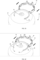
FIG. 13 is a perspective view of the shroud being attached to the mounting collar. -
FIG. 14 is another perspective view of the shroud being attached to the mounting collar. -
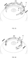
FIG. 15 is still another perspective view of the shroud being attached to the mounting collar. -
FIG. 16 is a perspective view of the shroud attached to the mounting collar. -
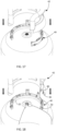
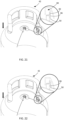
FIG. 17 is a perspective view of the handle being attached to the shroud. -
FIG. 18 is another perspective view of the handle being attached to the shroud. -
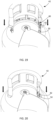
FIG. 19 is still another perspective view of the handle being attached to the shroud. -
FIG. 20 is yet another perspective view of the handle being attached to the shroud. -
FIG. 21 is another perspective view of the handle being attached to the shroud. -
FIG. 22 is still another perspective view of the handle being attached to the shroud. -
FIG. 23 is a perspective view of the handle attached to the shroud. -
FIG. 24 is another perspective view of the handle attached to the shroud. -
FIG. 25 is yet another perspective view of the handle attached to the shroud. -
FIG. 26 is a further perspective view of the handle attached to the shroud. - Embodiments of the invention relate to methods and systems that relate to a portable gas cylinder. The cylinder has a gas tank having an upper portion having a valve port and a collar partially surrounding the valve port. The collar has a body and a flange extending radially outwardly from the body. The cylinder also has a handle assembly attached to the gas tank. The handle assembly includes a shroud attached to the collar and a handle attached to the shroud. The shroud has a body, at least one upper protrusion projecting from the body above the flange of the collar to prevent downward movement of the shroud in a first direction relative to the collar, at least one lower protrusion projecting from the body below the flange of the collar to prevent upward movement of the shroud relative to the collar in a second direction opposite the first direction, a plurality of circumferentially spaced locking protrusions projecting from the body, and at least one anti-rotate element interacting with the collar to prevent rotation of the shroud relative to the collar. The handle has a body defining a channel in which the shroud is disposed, where the channel includes a plurality of openings in a wall thereof through which the locking protrusions extend to secure the handle to the shroud.
- With reference to the drawings, like reference numerals designate identical or corresponding parts throughout the several views. However, the inclusion of like elements in different views does not mean a given embodiment necessarily includes such elements or that all embodiments of the invention include such elements. The examples and figures are illustrative only and not meant to limit the invention, which is measured by the scope of the claims.
- Turning now to
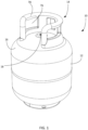
FIGS. 1-4 , a portable gas cylinder is shown generally atreference numeral 10. Thegas cylinder 10 includes agas tank 12 configured to store a suitable pressurized gas and ahandle assembly 14 attached to thegas tank 12. Thegas tank 12 may be made of a suitable material, such as metal, and thehandle assembly 14 may be made of a suitable non-metal material, such as plastic that provides improved ergonomics and portability relative to cylinders with steel handles. Thegas tank 12 includes anupper portion 16 having avalve port 18 and a mountingcollar 20 partially surrounding thevalve port 18. The mountingcollar 20 may be secured to theupper portion 16 in any suitable manner, such as by welding, or may alternatively be integrally formed with theupper portion 16. - The mounting
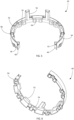
collar 20 has first and second ends 24 and 26 circumferentially spaced from one another to define a gap through which the valve extends, acurved base 22 that is attached to theupper portion 16, and acurved flange 28 extending radially outwardly from thebase 22. Theflange 28 includes at least onenotch 30, and in the illustrated embodiment twonotches 30 extending inward for receiving a corresponding protrusion on a shroud of thehandle assembly 14. Theflange 28 can also includeangled portions 32 at the first and second ends 24 and 26 of thecollar 20 for abutting an anti-rotate element of the shroud. The mountingcollar 20 is substantially C-shaped, although other configurations may be provided that provide a space for the valve. - Referring now to
FIGS. 5-12 in addition toFIG. 1 , thehandle assembly 14 will be discussed in detail. Thehandle assembly 14 includes ashroud 40 that attaches to the mountingcollar 20 and ahandle 42 that attaches to theshroud 40. Thehandle assembly 14 and mountingcollar 20 are designed to provide an open style handle that provides a space between ends of thehandle assembly 14 and mountingcollar 20 for a valve and its attachments to extend through, such as a valve having a ninety-degree bend. Thehandle assembly 14 thus provides an ergonomic and light weight handle that is usable with vertical valves and lateral valves. - Referring now to the
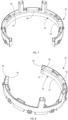
shroud 40 in detail and as shown inFIGS. 5 and 6 , theshroud 40 has acurved body 44 with first and second ends 46 and 48 circumferentially spaced from one another to define a gap through which the valve extends. Theshroud 40 is shaped similarly to the mountingcollar 20, such as substantially C-shaped, such that theshroud 40 surrounds and abuts the mountingcollar 20 and partially surrounds thevalve port 18 as shown inFIG. 7 . Theshroud 40 includes a plurality of circumferentially spaced lockingprotrusions 50 projecting from thebody 44, such as a plurality of protrusions projecting radially outward from an outer surface of theshroud 40. Theprotrusion 50 are provided near a bottom of theshroud 40 and are angled such that a lower portion of the protrusion project radially outward from the outer surface of theshroud 40 farther than an upper portion of the protrusion. - The
shroud 40 additionally includes at least oneupper protrusion 52 projecting from thebody 44 to prevent downward movement of theshroud 40 in a first direction relative to thecollar 20 and at least onelower protrusion 54 projecting from thebody 44 to prevent upward movement of theshroud 40 relative to the collar in a second direction opposite the first direction. As illustrated, theshroud 40 includes a plurality of upper andlower protrusions body 40 that define therebetween a space for receiving theflange 28 of the mountingcollar 20. The upper andlower protrusion body 44 such that theprotrusions protrusions shroud 40 is positioned relative to theflange 20 as shown inFIGS. 7 and 8 , a bottom surface of eachupper protrusion 52 abuts or is in close proximity to a top surface of theflange 28, and an upper surface of eachlower protrusion 54 abuts or is in close proximity to a bottom surface of theflange 28. - The
shroud 40 can additionally include at least oneprojection 56 extending upward in the first direction to serve as a guide for thehandle 42 as thehandle 42 is placed over theshroud 40 and for spacing a radio-frequency identification (RFID) element from thetank 12 to prevent or reduce interference caused by thetank 12. As shown, theshroud 40 includes a pair ofprojections 56 extending from respective ones of theupper protrusions 52 to extend into thehandle 42. The RFID element is placed on or near the top of one of theprojections 56 to be held between thehandle 42 andshroud 40 to prevent removal of the RFID element when thehandle 42 is attached to thetank 12. - To prevent rotation of the
shroud 40 relative to the mountingcollar 20, theshroud 40 includes at least one anti-rotate element that interacts with the mountingcollar 20. As illustrated, theshroud 40 includes a pair ofprotrusions 58 that engage a corresponding one of thenotches 30 to prevent rotation, and endportions protrusions 58 project radially inward from thebody 44 and are positioned in the space between the upper andlower protrusions notches 30. As shown, theprotrusions 58 are above respective ones of thelower protrusion 54. Theend portions body 44 at the first and second ends 46 and 48 at angles that correspond to theangled portions 32 to abut theangled portions 32 at the first and second ends 24 and 26 of the mountingcollar 20 to prevent rotation as shown inFIG. 8 . It will be appreciated that theend portions protrusions 58 can be used in combination with one another or separately from one another. - Referring now to the
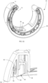
handle 42 in detail and as shown inFIGS. 1 ,2 , and9 , thehandle 42 has acurved body 70 with first and second ends 72 and 74 circumferentially spaced from one another to define a gap through which the valve extends and is shaped similarly to the mountingcollar 20 andshroud 40, such as substantially C-shaped. Thebody 70 includes a plurality ofopenings 76 extending therethrough to reduce weight of thehandle 42, and as shown three openings spaced around the body, although it will be appreciated that any suitable number of openings may be provided. Thebody 70 andopenings 76 definegrip areas 78 at a top of thehandle 42 for a user to grasp thehandle 42 to transport thecylinder 10. Thegrip areas 78 can also serve as hanging areas, for example the underside of themiddle grip area 78 defines arecess 88 for thehandle 42 to be hung, for example by a hook, as shown inFIG. 11 . - The
body 70 defines achannel 80 at its bottom for receiving theshroud 40 and mountingcollar 20. Thechannel 80 includes a plurality ofopenings 82 in awall 84 thereof through which the lockingprotrusions 50 extend to secure thehandle 42 to theshroud 40. As shown thewall 84 of thechannel 80 includes a plurality ofdeflectable tabs 86 each having at least one of theopenings 82. Thedeflectable tabs 86 are configured to be deflected outward by a respective one of the lockingprotrusions 50 during attachment of thehandle 42 to theshroud 40 until the lockingprotrusions 50 extend through theopenings 82, at which point thedeflectable tabs 86 return to their original position. Thedeflectable tabs 86 are spaced fromadjacent portions 90 of thewall 84 byslots 92 that extend a portion of the height of thechannel 80, and an inner surface of eachdeflectable tab 86 andadjacent portion 90 is configured to abut an outer surface of theshroud 40 when attached. - The
body 70 also includes anouter wall 96 outwardly spaced from thewall 84 and aninner wall 98 inwardly spaced from thewall 84 that forms with thewall 84 thechannel 80. Thewalls upper portion 16 when thehandle 42 is attached to thegas tank 12 to close off thechannel 80. Theinner wall 98 includes a plurality of spacedribs 100 on an inner surface thereof in thechannel 80 that abut thebody 22 of thecollar 20 when attached. Thebody 70 also includes receivingareas 102 defined within the body for receiving theprojections 56. - Turning now to
FIGS. 13-26 , the attachment of thehandle assembly 14 to thegas tank 12 will be described. Referring initially toFIGS. 13-16 , to attach theshroud 40 to thecollar 20, theshroud 40 is deflected from a first position shown inFIG. 13 to an intermediate position shown inFIG. 14 where the first and second ends 46 and 48 are deflected away from one another and then to a second position shown inFIG. 15 . For example, a user can grasp the first and second ends 46 and 48 and deflect the ends outward. Theshroud 40 is then positioned around thecollar 20 with the first and second ends 46 and 48 deflected away from one another and generally aligned with the first and second ends 24 and 26 of thecollar 20, and theshroud 40 is lowered onto thecollar 20 until at least some of theupper protrusions 52 abut theflange 28 of the mountingcollar 20. - The first and second ends 46 and 48 are then moved toward one another to the first position as shown in
FIG. 16 until the first and second ends 46 and 48 of theshroud 40 are proximate the first and second ends 24 and 26 of thecollar 20 and the first andsecond end portions shroud 40 abut theangled portions 32 at the first and second ends 24 and 26 of the mounting collar as shown inFIG. 8 to prevent rotation. Additionally, when in the position shown inFIG. 16 , theprotrusions 58 are received in thenotches 30 to prevent rotation of theshroud 40 relative to the mountingcollar 20, a bottom surface of eachupper protrusion 52 abuts a top surface of theflange 28 to prevent downward movement of theshroud 40 relative to thecollar 20, and an upper surface of eachlower protrusion 54 abuts a bottom surface of theflange 28 to prevent upward movement of theshroud 40 relative to thecollar 20. - Referring now to
FIGS. 17-26 , the attachment of thehandle 42 to the shroud will be described in detail.FIGs. 18-25 show thecylinder 10 with portions cutaway to illustrate the attachment of thehandle 42. To attach thehandle 42 to theshroud 40, the first and second ends 72 and 74 of thehandle 42 are aligned with the first and second ends 46 and 48 of theshroud 40 and theprojections 56 of theshroud 40 are aligned with the corresponding receivingareas 102 in thehandle 42. Thehandle 42 is then lowered onto theshroud 40. As thehandle 42 is lowered, theshroud 42 and mountingcollar 20 are received in thechannel 80 as shown inFIG. 20 . As thehandle 42 is continually lowered, thedeflectable tabs 86 are engaged by and deflected outward by the corresponding lockingprotrusions 50 as shown inFIG. 22 . Thehandle 42 is then lowered further until the lockingprotrusions 50 enter theopenings 82 in the respectivedeflectable tabs 86 and extend out of theopenings 82 to secure thehandle 42 to theshroud 40 as shown inFIG. 24 and thedeflectable tabs 86 return to their original position. In an embodiment, thedeflectable tabs 86 may make an audible sound as they snap back into their original position to indicate to the user that the connection is complete. When the lockingprotrusions 50 are disposed in theopenings 80, the bottom of thehandle 42 will be in contact with theupper portion 16 of thetank 12, and will be prevented from rotating by the anti-rotate elements on theshroud 40, such as theprotrusions 58 and theend portions walls upper portion 16 to conceal theshroud 40 and the mountingcollar 20. As shown inFIG. 25 , theprojections 56 of theshroud 40 are disposed in the corresponding receivingareas 102 in thehandle 42. - The aforementioned systems, components, (e.g., handles, cylinders, among others), and the like have been described with respect to interaction between several components and/or elements. It should be appreciated that such devices and elements can include those elements or sub-elements specified therein, some of the specified elements or sub-elements, and/or additional elements. Further yet, one or more elements and/or sub-elements may be combined into a single component to provide aggregate functionality. The elements may also interact with one or more other elements not specifically described herein.
- While the embodiments discussed herein have been related to the systems and methods discussed above, these embodiments are intended to be exemplary and are not intended to limit the applicability of these embodiments to only those discussions set forth herein.
Claims (14)
- A handle assembly for a cylinder comprising:a shroud (40) configured to attach to a collar of the cylinder to partially surround a valve port of the cylinder, the shroud (40) having a body (44) with first and second ends circumferentially spaced from one another to define a gap through which a valve is configured to extend, and a plurality of circumferentially spaced locking protrusions (50) projecting from the body; anda handle (42) configured to attach to the shroud (40), the handle (42) having a body (70) defining a channel (80) for receiving the shroud (40), and first and second ends circumferentially spaced from one another to define a gap through which the valve is configured to extend, characterized in that the channel (80) includes a plurality of openings (82) in a wall (84) thereof through which the locking protrusions (50) extend when the handle (42) is attached to the shroud to secure the handle to the shroud.
- The handle assembly according to claim 1, wherein the wall of the channel (80) includes a plurality of deflectable tabs (86) each having at least one of the openings, and wherein the deflectable tabs (86) are configured to be deflected by the locking protrusions (50) during attachment of the handle to the shroud until the locking protrusions extend through the openings.
- The handle assembly according to claim 2, wherein the locking protrusions (50) are angled such that a lower portion of each protrusion projects radially outward from an outer surface of the shroud (40) farther than an upper portion of the respective protrusion.
- The handle assembly according to any preceding claim, wherein the shroud (40) has a first orientation, wherein the shroud (40) is deflectable to a second orientation for attachment to the collar, and wherein when attached to the collar the shroud returns to the first orientation.
- The handle assembly according to any preceding claim, wherein the shroud (40) additionally includes at least one upper protrusion projecting from the body (44) to prevent downward movement of the shroud in a first direction relative to the collar and at least one lower protrusion projecting from the body (44) to prevent upward movement of the shroud relative to the collar in a second direction opposite the first direction.
- The handle assembly according to claim 5, wherein the upper and lower protrusions alternate around the shroud.
- The handle assembly according to any preceding claim, wherein the shroud (40) additionally includes at least one anti-rotate element configured to interact with the collar to prevent rotation of the shroud relative to the collar.
- The handle assembly according to claim 7, wherein the at least one anti-rotate element includes at least one protrusion configured to engage a corresponding recess in the collar to prevent rotation.
- The handle assembly according to claim 7 or 8, wherein the at least one anti-rotate element includes end portions at the first and second ends of the shroud (40) that are configured to abut end portions of the collar to prevent rotation.
- The handle assembly according to claim 9, wherein the end portions extend radially inward from the body at the first and second ends at angles to abut the end portions of the collar.
- The handle assembly according to any preceding claim, wherein the shroud (40) additionally includes at least one projection (56) extending upward in a first direction serving as a guide for the handle (42) and for spacing a radio-frequency identification element from the cylinder to reduce interference caused by the cylinder.
- The handle assembly according to any preceding claim, wherein the shroud (40) and handle (42) are plastic.
- A method of assembling a portable gas cylinder, the gas cylinder including a handle assembly (14) according to any preceding claim and a gas tank (12) having an upper portion having a valve port (18) and a collar (20) partially surrounding the valve port, the method comprising:deflecting the shroud (40) of the handle assembly from a first position to a second position where the ends of the shroud (40) are moved away from one another;positioning the shroud (40) around the collar (20) until the shroud surrounds the collar and is returned to the first position;lowering the handle (42) of the handle assembly (14) toward the shroud (40) until that the shroud and collar are received in the channel (80) of the handle and the locking protrusions (50) of the shroud are received in the openings in a wall of the channel.
- The method according to claim 13, wherein when the handle (42) is lowered, deflectable tabs (86) of the handle that each include one of the openings are engaged by and deflected outward by a corresponding one of the locking protrusions (50) until the locking protrusions enter the openings in the respective deflectable tabs and extend out of the openings to secure the handle to the shroud.
Applications Claiming Priority (2)
| Application Number | Priority Date | Filing Date | Title |
|---|---|---|---|
| US15/981,367 US10753541B2 (en) | 2018-05-16 | 2018-05-16 | Handle assembly for a portable pressurized gas cylinder |
| PCT/US2019/032356 WO2019222310A1 (en) | 2018-05-16 | 2019-05-15 | Handle assembly for a portable pressurized gas cylinder |
Publications (2)
| Publication Number | Publication Date |
|---|---|
| EP3794271A1 EP3794271A1 (en) | 2021-03-24 |
| EP3794271B1 true EP3794271B1 (en) | 2023-06-28 |
Family
ID=66821377
Family Applications (1)
| Application Number | Title | Priority Date | Filing Date |
|---|---|---|---|
| EP19729951.4A Active EP3794271B1 (en) | 2018-05-16 | 2019-05-15 | Handle assembly for a portable pressurized gas cylinder |
Country Status (8)
| Country | Link |
|---|---|
| US (1) | US10753541B2 (en) |
| EP (1) | EP3794271B1 (en) |
| AU (1) | AU2019271185B2 (en) |
| CA (1) | CA3100354C (en) |
| ES (1) | ES2954568T3 (en) |
| PL (1) | PL3794271T3 (en) |
| PT (1) | PT3794271T (en) |
| WO (1) | WO2019222310A1 (en) |
Cited By (1)
| Publication number | Priority date | Publication date | Assignee | Title |
|---|---|---|---|---|
| WO2026009056A1 (en) * | 2025-05-29 | 2026-01-08 | Evas Ev Aletleri̇ Sanayi̇ Anoni̇m Şi̇rketi̇ | Shield device for pressurized gas cylinder |
Families Citing this family (14)
| Publication number | Priority date | Publication date | Assignee | Title |
|---|---|---|---|---|
| USD920468S1 (en) * | 2018-05-16 | 2021-05-25 | Amtrol Licensing Inc. | Handle for a cylinder |
| USD921832S1 (en) * | 2018-09-06 | 2021-06-08 | The Japan Steel Works, Ltd. | Storage container for high pressure liquid or gas |
| US11473733B2 (en) * | 2019-02-27 | 2022-10-18 | Amtrol Licensing Inc. | Foot for a portable pressurized gas cylinder |
| USD912199S1 (en) * | 2019-04-05 | 2021-03-02 | Amtrol Licensing Inc. | Cylinder |
| USD930783S1 (en) * | 2019-09-03 | 2021-09-14 | Amtrol Licensing, Inc. | Handle |
| USD949283S1 (en) * | 2019-11-27 | 2022-04-19 | Worthington Industries, Inc. | Tank |
| US11415449B2 (en) | 2020-04-15 | 2022-08-16 | Worthington Cylinders Corporation | Cylinder attachment |
| USD981528S1 (en) * | 2020-04-15 | 2023-03-21 | Worthington Cylinders Corporation | Canister attachment device |
| US11585491B2 (en) * | 2020-08-06 | 2023-02-21 | Amtrol Licensing Inc. | Handle for a portable cylinder |
| USD930109S1 (en) * | 2020-08-06 | 2021-09-07 | Amtrol Licensing, Inc. | Handle |
| USD1055212S1 (en) * | 2022-07-25 | 2024-12-24 | Amtrol Licensing Inc. | Handle |
| USD1064179S1 (en) | 2022-08-05 | 2025-02-25 | Amtrol Licensing Inc. | Cylinder stand |
| US12129970B2 (en) * | 2023-02-17 | 2024-10-29 | Amtrol Licensing Inc. | Handle for a portable cylinder |
| USD1124227S1 (en) | 2023-02-17 | 2026-04-28 | Amtrol Licensing Inc. | Handle |
Citations (1)
| Publication number | Priority date | Publication date | Assignee | Title |
|---|---|---|---|---|
| WO2013156698A1 (en) * | 2012-04-19 | 2013-10-24 | L'air Liquide,Societe Anonyme Pour L'etude Et L'exploitation Des Procedes Georges Claude | Protective cap for a pressurised fluid cylinder valve and production method thereof |
Family Cites Families (13)
| Publication number | Priority date | Publication date | Assignee | Title |
|---|---|---|---|---|
| US3776412A (en) | 1972-09-27 | 1973-12-04 | Luxfer Usa Ltd | Gas cylinder structure and valve-protecting element therefor |
| DE3931158A1 (en) | 1989-09-19 | 1991-03-28 | Roland Man Druckmasch | DEVICE FOR THE THREE-SIDED CUTTING OF PRINT EXPLARES |
| DE9408638U1 (en) | 1994-05-26 | 1994-07-21 | Sauerstoffwerk Friedrich Guttroff GmbH, 97877 Wertheim | Valve protection |
| FR2729739B1 (en) | 1995-01-25 | 1997-04-25 | Soc D Anciennes Fonderies Et A | PROTECTORS FOR INDUSTRIAL, DOMESTIC OR MEDICAL GAS BOTTLES PROVIDED WITH A SELF-TIGHTENING SAFETY COLLAR |
| US5709252A (en) * | 1995-06-06 | 1998-01-20 | Progas, Inc. | Natural gas distribution system |
| FR2738897B1 (en) | 1995-09-19 | 1997-12-05 | Butagaz | COMPRESSED OR DISSOLVED LIQUEFIED GAS STORAGE CONTAINER ASSEMBLY, PRESSURIZED GAS STORAGE CONTAINER, AND HANDLING CAP FOR SUCH A CONTAINER |
| DE19639997B4 (en) | 1996-09-18 | 2004-07-08 | Yigitbas, Gökhan | Safety device for a cylindrical pressure gas container |
| FR2791757B1 (en) | 1999-04-01 | 2001-06-15 | Air Liquide | COMPOSITE OPEN HAT FROM LARGE INDUSTRIAL AND MEDICAL GAS BOTTLES |
| DE10146261B4 (en) | 2001-09-20 | 2008-05-29 | Air Liquide Deutschland Gmbh | Valve guard |
| DE10308676B4 (en) | 2003-02-28 | 2008-04-03 | Adam Opel Ag | Protective cap for a cylinder valve of a gas cylinder |
| TR200502730A2 (en) | 2005-07-13 | 2007-02-21 | Aygaz Anon�M ��Rket� | B |
| PT2933547T (en) | 2014-04-17 | 2019-09-30 | Schmitt Prof Moehlmann & Collegen Wirtsch Insolvenzverwalter Aktiengesellschaft | Valve protection basket for the protection of gas cylinder valves |
| US9932148B2 (en) | 2015-01-23 | 2018-04-03 | Amtrol Licensing Inc. | Handle assembly for a portable pressurized gas cylinder |
-
2018
- 2018-05-16 US US15/981,367 patent/US10753541B2/en active Active
-
2019
- 2019-05-15 PL PL19729951.4T patent/PL3794271T3/en unknown
- 2019-05-15 CA CA3100354A patent/CA3100354C/en active Active
- 2019-05-15 EP EP19729951.4A patent/EP3794271B1/en active Active
- 2019-05-15 AU AU2019271185A patent/AU2019271185B2/en active Active
- 2019-05-15 ES ES19729951T patent/ES2954568T3/en active Active
- 2019-05-15 WO PCT/US2019/032356 patent/WO2019222310A1/en not_active Ceased
- 2019-05-15 PT PT197299514T patent/PT3794271T/en unknown
Patent Citations (1)
| Publication number | Priority date | Publication date | Assignee | Title |
|---|---|---|---|---|
| WO2013156698A1 (en) * | 2012-04-19 | 2013-10-24 | L'air Liquide,Societe Anonyme Pour L'etude Et L'exploitation Des Procedes Georges Claude | Protective cap for a pressurised fluid cylinder valve and production method thereof |
Cited By (1)
| Publication number | Priority date | Publication date | Assignee | Title |
|---|---|---|---|---|
| WO2026009056A1 (en) * | 2025-05-29 | 2026-01-08 | Evas Ev Aletleri̇ Sanayi̇ Anoni̇m Şi̇rketi̇ | Shield device for pressurized gas cylinder |
Also Published As
| Publication number | Publication date |
|---|---|
| CA3100354A1 (en) | 2019-11-21 |
| AU2019271185A1 (en) | 2020-12-03 |
| US20190353305A1 (en) | 2019-11-21 |
| CA3100354C (en) | 2024-05-14 |
| PL3794271T3 (en) | 2023-12-11 |
| EP3794271A1 (en) | 2021-03-24 |
| ES2954568T3 (en) | 2023-11-23 |
| AU2019271185B2 (en) | 2024-03-21 |
| PT3794271T (en) | 2023-08-24 |
| US10753541B2 (en) | 2020-08-25 |
| WO2019222310A1 (en) | 2019-11-21 |
Similar Documents
| Publication | Publication Date | Title |
|---|---|---|
| EP3794271B1 (en) | Handle assembly for a portable pressurized gas cylinder | |
| EP3048358B1 (en) | Handle assembly for a portable pressurized gas cylinder | |
| US12181104B2 (en) | Handle for a portable cylinder | |
| US7780043B2 (en) | Fastener device for fastening a pump or a valve onto a receptacle neck and a fluid dispenser including such a fastener device | |
| EP3931483B1 (en) | Foot for a portable pressurized gas cylinder | |
| US20150083237A1 (en) | Protective cap for a pressurised fluid cylinder valve and production method thereof | |
| KR20130109993A (en) | Suspension device for containers | |
| EP3604158B1 (en) | Handle, and container with handle | |
| US20140097312A1 (en) | Quick attachment bracket for securing a first item to a second item | |
| US20250020286A1 (en) | Handle for a portable cylinder | |
| EP4025825B1 (en) | Handle assembly for a portable pressurized gas cylinder | |
| US2567322A (en) | Cover for pails | |
| US20020148833A1 (en) | Metal packaging with safety cap | |
| US6520707B1 (en) | Can clip device with toy construction set engagement elements | |
| JP2004524233A (en) | Fluid dispenser | |
| JP3223807U (en) | cup | |
| HK9395A (en) | Protective device for liquefied gas vessel | |
| JP3239514U (en) | planter |
Legal Events
| Date | Code | Title | Description |
|---|---|---|---|
| STAA | Information on the status of an ep patent application or granted ep patent |
Free format text: STATUS: UNKNOWN |
|
| STAA | Information on the status of an ep patent application or granted ep patent |
Free format text: STATUS: THE INTERNATIONAL PUBLICATION HAS BEEN MADE |
|
| PUAI | Public reference made under article 153(3) epc to a published international application that has entered the european phase |
Free format text: ORIGINAL CODE: 0009012 |
|
| STAA | Information on the status of an ep patent application or granted ep patent |
Free format text: STATUS: REQUEST FOR EXAMINATION WAS MADE |
|
| 17P | Request for examination filed |
Effective date: 20201125 |
|
| AK | Designated contracting states |
Kind code of ref document: A1 Designated state(s): AL AT BE BG CH CY CZ DE DK EE ES FI FR GB GR HR HU IE IS IT LI LT LU LV MC MK MT NL NO PL PT RO RS SE SI SK SM TR |
|
| AX | Request for extension of the european patent |
Extension state: BA ME |
|
| DAV | Request for validation of the european patent (deleted) | ||
| DAX | Request for extension of the european patent (deleted) | ||
| GRAP | Despatch of communication of intention to grant a patent |
Free format text: ORIGINAL CODE: EPIDOSNIGR1 |
|
| STAA | Information on the status of an ep patent application or granted ep patent |
Free format text: STATUS: GRANT OF PATENT IS INTENDED |
|
| INTG | Intention to grant announced |
Effective date: 20221221 |
|
| GRAS | Grant fee paid |
Free format text: ORIGINAL CODE: EPIDOSNIGR3 |
|
| GRAA | (expected) grant |
Free format text: ORIGINAL CODE: 0009210 |
|
| STAA | Information on the status of an ep patent application or granted ep patent |
Free format text: STATUS: THE PATENT HAS BEEN GRANTED |
|
| AK | Designated contracting states |
Kind code of ref document: B1 Designated state(s): AL AT BE BG CH CY CZ DE DK EE ES FI FR GB GR HR HU IE IS IT LI LT LU LV MC MK MT NL NO PL PT RO RS SE SI SK SM TR |
|
| REG | Reference to a national code |
Ref country code: CH Ref legal event code: EP |
|
| REG | Reference to a national code |
Ref country code: AT Ref legal event code: REF Ref document number: 1582965 Country of ref document: AT Kind code of ref document: T Effective date: 20230715 |
|
| REG | Reference to a national code |
Ref country code: IE Ref legal event code: FG4D |
|
| REG | Reference to a national code |
Ref country code: DE Ref legal event code: R096 Ref document number: 602019031716 Country of ref document: DE |
|
| REG | Reference to a national code |
Ref country code: PT Ref legal event code: SC4A Ref document number: 3794271 Country of ref document: PT Date of ref document: 20230824 Kind code of ref document: T Free format text: AVAILABILITY OF NATIONAL TRANSLATION Effective date: 20230821 |
|
| REG | Reference to a national code |
Ref country code: NL Ref legal event code: FP |
|
| REG | Reference to a national code |
Ref country code: LT Ref legal event code: MG9D |
|
| PG25 | Lapsed in a contracting state [announced via postgrant information from national office to epo] |
Ref country code: SE Free format text: LAPSE BECAUSE OF FAILURE TO SUBMIT A TRANSLATION OF THE DESCRIPTION OR TO PAY THE FEE WITHIN THE PRESCRIBED TIME-LIMIT Effective date: 20230628 Ref country code: NO Free format text: LAPSE BECAUSE OF FAILURE TO SUBMIT A TRANSLATION OF THE DESCRIPTION OR TO PAY THE FEE WITHIN THE PRESCRIBED TIME-LIMIT Effective date: 20230928 |
|
| REG | Reference to a national code |
Ref country code: AT Ref legal event code: MK05 Ref document number: 1582965 Country of ref document: AT Kind code of ref document: T Effective date: 20230628 |
|
| PG25 | Lapsed in a contracting state [announced via postgrant information from national office to epo] |
Ref country code: RS Free format text: LAPSE BECAUSE OF FAILURE TO SUBMIT A TRANSLATION OF THE DESCRIPTION OR TO PAY THE FEE WITHIN THE PRESCRIBED TIME-LIMIT Effective date: 20230628 Ref country code: LV Free format text: LAPSE BECAUSE OF FAILURE TO SUBMIT A TRANSLATION OF THE DESCRIPTION OR TO PAY THE FEE WITHIN THE PRESCRIBED TIME-LIMIT Effective date: 20230628 Ref country code: LT Free format text: LAPSE BECAUSE OF FAILURE TO SUBMIT A TRANSLATION OF THE DESCRIPTION OR TO PAY THE FEE WITHIN THE PRESCRIBED TIME-LIMIT Effective date: 20230628 Ref country code: HR Free format text: LAPSE BECAUSE OF FAILURE TO SUBMIT A TRANSLATION OF THE DESCRIPTION OR TO PAY THE FEE WITHIN THE PRESCRIBED TIME-LIMIT Effective date: 20230628 |
|
| REG | Reference to a national code |
Ref country code: GR Ref legal event code: EP Ref document number: 20230401685 Country of ref document: GR Effective date: 20231113 |
|
| PG25 | Lapsed in a contracting state [announced via postgrant information from national office to epo] |
Ref country code: FI Free format text: LAPSE BECAUSE OF FAILURE TO SUBMIT A TRANSLATION OF THE DESCRIPTION OR TO PAY THE FEE WITHIN THE PRESCRIBED TIME-LIMIT Effective date: 20230628 |
|
| PG25 | Lapsed in a contracting state [announced via postgrant information from national office to epo] |
Ref country code: SK Free format text: LAPSE BECAUSE OF FAILURE TO SUBMIT A TRANSLATION OF THE DESCRIPTION OR TO PAY THE FEE WITHIN THE PRESCRIBED TIME-LIMIT Effective date: 20230628 |
|
| PG25 | Lapsed in a contracting state [announced via postgrant information from national office to epo] |
Ref country code: IS Free format text: LAPSE BECAUSE OF FAILURE TO SUBMIT A TRANSLATION OF THE DESCRIPTION OR TO PAY THE FEE WITHIN THE PRESCRIBED TIME-LIMIT Effective date: 20231028 |
|
| PG25 | Lapsed in a contracting state [announced via postgrant information from national office to epo] |
Ref country code: SM Free format text: LAPSE BECAUSE OF FAILURE TO SUBMIT A TRANSLATION OF THE DESCRIPTION OR TO PAY THE FEE WITHIN THE PRESCRIBED TIME-LIMIT Effective date: 20230628 Ref country code: SK Free format text: LAPSE BECAUSE OF FAILURE TO SUBMIT A TRANSLATION OF THE DESCRIPTION OR TO PAY THE FEE WITHIN THE PRESCRIBED TIME-LIMIT Effective date: 20230628 Ref country code: RO Free format text: LAPSE BECAUSE OF FAILURE TO SUBMIT A TRANSLATION OF THE DESCRIPTION OR TO PAY THE FEE WITHIN THE PRESCRIBED TIME-LIMIT Effective date: 20230628 Ref country code: IS Free format text: LAPSE BECAUSE OF FAILURE TO SUBMIT A TRANSLATION OF THE DESCRIPTION OR TO PAY THE FEE WITHIN THE PRESCRIBED TIME-LIMIT Effective date: 20231028 Ref country code: EE Free format text: LAPSE BECAUSE OF FAILURE TO SUBMIT A TRANSLATION OF THE DESCRIPTION OR TO PAY THE FEE WITHIN THE PRESCRIBED TIME-LIMIT Effective date: 20230628 Ref country code: CZ Free format text: LAPSE BECAUSE OF FAILURE TO SUBMIT A TRANSLATION OF THE DESCRIPTION OR TO PAY THE FEE WITHIN THE PRESCRIBED TIME-LIMIT Effective date: 20230628 Ref country code: AT Free format text: LAPSE BECAUSE OF FAILURE TO SUBMIT A TRANSLATION OF THE DESCRIPTION OR TO PAY THE FEE WITHIN THE PRESCRIBED TIME-LIMIT Effective date: 20230628 |
|
| PG25 | Lapsed in a contracting state [announced via postgrant information from national office to epo] |
Ref country code: PL Free format text: LAPSE BECAUSE OF FAILURE TO SUBMIT A TRANSLATION OF THE DESCRIPTION OR TO PAY THE FEE WITHIN THE PRESCRIBED TIME-LIMIT Effective date: 20230628 |
|
| REG | Reference to a national code |
Ref country code: DE Ref legal event code: R097 Ref document number: 602019031716 Country of ref document: DE |
|
| PG25 | Lapsed in a contracting state [announced via postgrant information from national office to epo] |
Ref country code: DK Free format text: LAPSE BECAUSE OF FAILURE TO SUBMIT A TRANSLATION OF THE DESCRIPTION OR TO PAY THE FEE WITHIN THE PRESCRIBED TIME-LIMIT Effective date: 20230628 |
|
| PLBE | No opposition filed within time limit |
Free format text: ORIGINAL CODE: 0009261 |
|
| STAA | Information on the status of an ep patent application or granted ep patent |
Free format text: STATUS: NO OPPOSITION FILED WITHIN TIME LIMIT |
|
| PG25 | Lapsed in a contracting state [announced via postgrant information from national office to epo] |
Ref country code: IT Free format text: LAPSE BECAUSE OF FAILURE TO SUBMIT A TRANSLATION OF THE DESCRIPTION OR TO PAY THE FEE WITHIN THE PRESCRIBED TIME-LIMIT Effective date: 20230628 |
|
| 26N | No opposition filed |
Effective date: 20240402 |
|
| PG25 | Lapsed in a contracting state [announced via postgrant information from national office to epo] |
Ref country code: SI Free format text: LAPSE BECAUSE OF FAILURE TO SUBMIT A TRANSLATION OF THE DESCRIPTION OR TO PAY THE FEE WITHIN THE PRESCRIBED TIME-LIMIT Effective date: 20230628 |
|
| PG2D | Information on lapse in contracting state deleted |
Ref country code: PL |
|
| PG25 | Lapsed in a contracting state [announced via postgrant information from national office to epo] |
Ref country code: BG Free format text: LAPSE BECAUSE OF FAILURE TO SUBMIT A TRANSLATION OF THE DESCRIPTION OR TO PAY THE FEE WITHIN THE PRESCRIBED TIME-LIMIT Effective date: 20230628 |
|
| PG25 | Lapsed in a contracting state [announced via postgrant information from national office to epo] |
Ref country code: BG Free format text: LAPSE BECAUSE OF FAILURE TO SUBMIT A TRANSLATION OF THE DESCRIPTION OR TO PAY THE FEE WITHIN THE PRESCRIBED TIME-LIMIT Effective date: 20230628 |
|
| REG | Reference to a national code |
Ref country code: DE Ref legal event code: R119 Ref document number: 602019031716 Country of ref document: DE |
|
| REG | Reference to a national code |
Ref country code: CH Ref legal event code: PL |
|
| PG25 | Lapsed in a contracting state [announced via postgrant information from national office to epo] |
Ref country code: MC Free format text: LAPSE BECAUSE OF FAILURE TO SUBMIT A TRANSLATION OF THE DESCRIPTION OR TO PAY THE FEE WITHIN THE PRESCRIBED TIME-LIMIT Effective date: 20230628 |
|
| PG25 | Lapsed in a contracting state [announced via postgrant information from national office to epo] |
Ref country code: LU Free format text: LAPSE BECAUSE OF NON-PAYMENT OF DUE FEES Effective date: 20240515 |
|
| PG25 | Lapsed in a contracting state [announced via postgrant information from national office to epo] |
Ref country code: MC Free format text: LAPSE BECAUSE OF FAILURE TO SUBMIT A TRANSLATION OF THE DESCRIPTION OR TO PAY THE FEE WITHIN THE PRESCRIBED TIME-LIMIT Effective date: 20230628 Ref country code: LU Free format text: LAPSE BECAUSE OF NON-PAYMENT OF DUE FEES Effective date: 20240515 Ref country code: CH Free format text: LAPSE BECAUSE OF NON-PAYMENT OF DUE FEES Effective date: 20240531 |
|
| PG25 | Lapsed in a contracting state [announced via postgrant information from national office to epo] |
Ref country code: DE Free format text: LAPSE BECAUSE OF NON-PAYMENT OF DUE FEES Effective date: 20241203 |
|
| PGFP | Annual fee paid to national office [announced via postgrant information from national office to epo] |
Ref country code: NL Payment date: 20250522 Year of fee payment: 7 |
|
| PGFP | Annual fee paid to national office [announced via postgrant information from national office to epo] |
Ref country code: PL Payment date: 20250505 Year of fee payment: 7 |
|
| PGFP | Annual fee paid to national office [announced via postgrant information from national office to epo] |
Ref country code: ES Payment date: 20250616 Year of fee payment: 7 Ref country code: GB Payment date: 20250522 Year of fee payment: 7 |
|
| PGFP | Annual fee paid to national office [announced via postgrant information from national office to epo] |
Ref country code: BE Payment date: 20250520 Year of fee payment: 7 |
|
| PGFP | Annual fee paid to national office [announced via postgrant information from national office to epo] |
Ref country code: PT Payment date: 20250507 Year of fee payment: 7 |
|
| PGFP | Annual fee paid to national office [announced via postgrant information from national office to epo] |
Ref country code: FR Payment date: 20250523 Year of fee payment: 7 |
|
| PGFP | Annual fee paid to national office [announced via postgrant information from national office to epo] |
Ref country code: GR Payment date: 20250519 Year of fee payment: 7 |
|
| PGFP | Annual fee paid to national office [announced via postgrant information from national office to epo] |
Ref country code: IE Payment date: 20250522 Year of fee payment: 7 |
|
| PG25 | Lapsed in a contracting state [announced via postgrant information from national office to epo] |
Ref country code: HU Free format text: LAPSE BECAUSE OF FAILURE TO SUBMIT A TRANSLATION OF THE DESCRIPTION OR TO PAY THE FEE WITHIN THE PRESCRIBED TIME-LIMIT; INVALID AB INITIO Effective date: 20190515 |
|
| PGFP | Annual fee paid to national office [announced via postgrant information from national office to epo] |
Ref country code: CY Payment date: 20250509 Year of fee payment: 7 |