EP3792793A1 - Système informatique, procédé d'affichage d'écran d'ouverture de session, et programme - Google Patents
Système informatique, procédé d'affichage d'écran d'ouverture de session, et programme Download PDFInfo
- Publication number
- EP3792793A1 EP3792793A1 EP20194855.1A EP20194855A EP3792793A1 EP 3792793 A1 EP3792793 A1 EP 3792793A1 EP 20194855 A EP20194855 A EP 20194855A EP 3792793 A1 EP3792793 A1 EP 3792793A1
- Authority
- EP
- European Patent Office
- Prior art keywords
- login
- user
- information
- screen
- processing system
- Prior art date
- Legal status (The legal status is an assumption and is not a legal conclusion. Google has not performed a legal analysis and makes no representation as to the accuracy of the status listed.)
- Granted
Links
- 238000000034 method Methods 0.000 title claims abstract description 443
- 230000008569 process Effects 0.000 claims abstract description 184
- 230000010365 information processing Effects 0.000 claims abstract description 169
- 238000004891 communication Methods 0.000 description 82
- 230000006870 function Effects 0.000 description 22
- 238000012545 processing Methods 0.000 description 6
- 238000005516 engineering process Methods 0.000 description 5
- 238000010586 diagram Methods 0.000 description 4
- 230000007246 mechanism Effects 0.000 description 4
- 235000014510 cooky Nutrition 0.000 description 3
- 230000002093 peripheral effect Effects 0.000 description 3
- 238000003825 pressing Methods 0.000 description 3
- 238000007639 printing Methods 0.000 description 3
- 230000008859 change Effects 0.000 description 2
- 238000012790 confirmation Methods 0.000 description 2
- 235000006481 Colocasia esculenta Nutrition 0.000 description 1
- 240000004270 Colocasia esculenta var. antiquorum Species 0.000 description 1
- 238000006243 chemical reaction Methods 0.000 description 1
- 238000012217 deletion Methods 0.000 description 1
- 230000037430 deletion Effects 0.000 description 1
- 238000009792 diffusion process Methods 0.000 description 1
- 238000003384 imaging method Methods 0.000 description 1
- 238000012986 modification Methods 0.000 description 1
- 230000004048 modification Effects 0.000 description 1
- 230000008520 organization Effects 0.000 description 1
- 230000000717 retained effect Effects 0.000 description 1
- 238000012546 transfer Methods 0.000 description 1
- 230000007704 transition Effects 0.000 description 1
- 238000013519 translation Methods 0.000 description 1
Images


Classifications
-
- H—ELECTRICITY
- H04—ELECTRIC COMMUNICATION TECHNIQUE
- H04L—TRANSMISSION OF DIGITAL INFORMATION, e.g. TELEGRAPHIC COMMUNICATION
- H04L63/00—Network architectures or network communication protocols for network security
- H04L63/08—Network architectures or network communication protocols for network security for authentication of entities
-
- G—PHYSICS
- G06—COMPUTING; CALCULATING OR COUNTING
- G06F—ELECTRIC DIGITAL DATA PROCESSING
- G06F3/00—Input arrangements for transferring data to be processed into a form capable of being handled by the computer; Output arrangements for transferring data from processing unit to output unit, e.g. interface arrangements
- G06F3/12—Digital output to print unit, e.g. line printer, chain printer
- G06F3/1201—Dedicated interfaces to print systems
- G06F3/1223—Dedicated interfaces to print systems specifically adapted to use a particular technique
- G06F3/1237—Print job management
- G06F3/1238—Secure printing, e.g. user identification, user rights for device usage, unallowed content, blanking portions or fields of a page, releasing held jobs
-
- G—PHYSICS
- G06—COMPUTING; CALCULATING OR COUNTING
- G06F—ELECTRIC DIGITAL DATA PROCESSING
- G06F21/00—Security arrangements for protecting computers, components thereof, programs or data against unauthorised activity
- G06F21/30—Authentication, i.e. establishing the identity or authorisation of security principals
- G06F21/31—User authentication
-
- G—PHYSICS
- G06—COMPUTING; CALCULATING OR COUNTING
- G06F—ELECTRIC DIGITAL DATA PROCESSING
- G06F21/00—Security arrangements for protecting computers, components thereof, programs or data against unauthorised activity
- G06F21/60—Protecting data
- G06F21/606—Protecting data by securing the transmission between two devices or processes
- G06F21/608—Secure printing
-
- G—PHYSICS
- G06—COMPUTING; CALCULATING OR COUNTING
- G06F—ELECTRIC DIGITAL DATA PROCESSING
- G06F3/00—Input arrangements for transferring data to be processed into a form capable of being handled by the computer; Output arrangements for transferring data from processing unit to output unit, e.g. interface arrangements
- G06F3/12—Digital output to print unit, e.g. line printer, chain printer
- G06F3/1201—Dedicated interfaces to print systems
- G06F3/1202—Dedicated interfaces to print systems specifically adapted to achieve a particular effect
- G06F3/1203—Improving or facilitating administration, e.g. print management
-
- G—PHYSICS
- G06—COMPUTING; CALCULATING OR COUNTING
- G06F—ELECTRIC DIGITAL DATA PROCESSING
- G06F2221/00—Indexing scheme relating to security arrangements for protecting computers, components thereof, programs or data against unauthorised activity
- G06F2221/21—Indexing scheme relating to G06F21/00 and subgroups addressing additional information or applications relating to security arrangements for protecting computers, components thereof, programs or data against unauthorised activity
- G06F2221/2139—Recurrent verification
-
- H—ELECTRICITY
- H04—ELECTRIC COMMUNICATION TECHNIQUE
- H04L—TRANSMISSION OF DIGITAL INFORMATION, e.g. TELEGRAPHIC COMMUNICATION
- H04L2463/00—Additional details relating to network architectures or network communication protocols for network security covered by H04L63/00
- H04L2463/082—Additional details relating to network architectures or network communication protocols for network security covered by H04L63/00 applying multi-factor authentication
Definitions
- An aspect of this disclosure relates to a computer system, a login screen display method, and a program.
- a known information processing system provides software to a user via a network.
- the user can use services provided by the information processing system from a client terminal by preparing a certain environment including the client terminal such as a personal computer (PC), a web browser running on the client terminal, and an Internet connection environment.
- a client terminal such as a personal computer (PC)
- PC personal computer
- web browser running on the client terminal
- Internet connection environment an environment including the client terminal such as a personal computer (PC), a web browser running on the client terminal, and an Internet connection environment.
- Japanese Patent No. 6375877 discloses a technology for simplifying login operations of a user in consideration of the convenience of the user. Specifically, Japanese Patent No. 6375877 discloses a login method that enables a user to log in by simply selecting the user from a user list and then entering a password instead of entering an email address and a password.
- a computer system that includes an information processing system configured to authenticate a user using one of multiple login methods and a terminal configured to request the information processing system to authenticate the user.
- the terminal includes a process controller configured to determine a login method based on a previously-used login method and a display controller configured to display a login screen corresponding to the login method determined by the process controller.
- An aspect of this disclosure makes it possible to provide a computer system that can display an appropriate login screen without identifying a user.
- ⁇ such as companies subscribe to services provided by an information processing system and members of the organizations use the services as users.
- the organizations subscribing to the services are managed in units called tenants.
- the users of the services are, for example, employees of companies, and each user belongs to one or more tenants. Users who can execute the subscribed services are set by, for example, an administrator, and available services are determined for each user.
- a portal screen including a list of services available to the user is displayed on a terminal of the user.
- the services are provided as web applications, and application icons corresponding to the services are displayed on the portal screen.
- a service processes vouchers according to a predetermined procedure to reduce the workload of the user.
- workflow indicates automatic execution of one or more processes on electronic data in a predetermined order.
- a portal screen for the user's work is displayed when the user logs in, the service provided by the information processing system may be referred to as a workplace.
- FIG. 1 is a drawing illustrating the outline of a process where a user logs into a computer system 1.
- the first terminal 20 can display the login screen corresponding to the login method permitted by the tenant without requiring the user to input identification information such as an email address for identifying or specifying the user. For example, if the user has once logged in with the login method "(C) Using external service", because an external service 70 does not require an email address for authentication (a login screen corresponding to the login method using the external service does not request an email address), the occasions where the information processing system 50 unnecessarily requests the user to input an email address can be reduced.
- a tenant indicates a group of customers who share the same software.
- a tenant indicates a group of users who have use rights of multiple software instances existing in the system.
- the information processing system 50 may be implemented by one or more information processing apparatuses.
- the information processing apparatus may also be referred to as a server.
- the information processing apparatus is normally placed on the Internet. However, the information processing apparatus may be placed in a local network (inside of the firewall) of, for example, a company.
- One or more information processing apparatuses may be referred to as a cloud system.
- a cloud system is a system that uses cloud computing, and cloud computing is a technology where resources on a network are used without being aware of specific hardware resources.
- a cloud system indicates an information processing system on the Internet. However, a cloud system may also be provided on a local network.
- FIG. 2 is a block diagram illustrating an example of a configuration of the computer system 1.
- a customer environment 8 is connected to the information processing system 50 via a network N1 such as the Internet.
- the network N1 may also be a telephone line such as a mobile phone network.
- the customer environment 8 is an environment of a customer using services provided by the information processing system 50, and the customer may be an organization such as a company, a group, an educational institution, a government agency, or a department. People who have a certain employment relationship with the customer are referred to users.
- the users include a general user and an administrator.
- the customer environment 8 includes one or more electronic apparatuses 10, a first terminal 20, a second terminal 30, and a firewall (FW) 7 that are connected to each other via a network N2 such as a local area network (LAN).
- the information processing system 50 includes one or more information processing apparatuses 49 connected to the network N1.
- An image forming apparatus 10a is an example of the electronic apparatus 10.
- the image forming apparatus 10a may be, for example, a laser printer, a multifunction printer, or a multifunction peripheral (product or printer).
- An electronic blackboard 10b is another example of the electronic apparatus 10.
- Other examples of electronic apparatuses 10 include output devices such as a projector (PJ) and a digital signage, a head-up display (HUD), an industrial machine, an imaging device, a sound collector, a medical device, a network home appliance, an automobile (Connected Car), a notebook PC, a mobile phone, a smartphone, a tablet terminal, a game machine, a personal digital assistant (PDA), a digital camera, a wearable PC, and a desktop PC.
- the electronic apparatus 10 of the present embodiment functions as a terminal used by a user registered in the information processing system 50 to use a service.
- the user logs into the information processing system 50 from the electronic apparatus 10, selects an application (application software) whose use right is assigned to the user, and receives a service provided by the information processing system 50.
- applications application software
- the first terminal 20 is an information processing apparatus such as a smartphone, a mobile phone, a tablet PC, a desktop PC, or a notebook PC used by a general user.
- the first terminal 20 includes a program such as a web browser including a screen display function.
- the program is not limited to a web browser as long as it includes a function to display a screen based on screen information received from the information processing system 50.
- a program dedicated to the information processing system 50 may also be used for this purpose.
- the second terminal 30 is an information processing apparatus such as a smartphone, a mobile phone, a tablet PC, a desktop PC, or a notebook PC used by the administrator.
- the second terminal 30 includes a program such as a web browser including a screen display function.
- the program is not limited to a web browser as long as it includes a function to display a screen based on screen information received from the information processing system 50.
- a program dedicated to the information processing system 50 may also be used for this purpose.
- the firewall 7 is an apparatus for preventing intrusion from the outside into the customer environment 8, and all communications from the customer environment 8 are monitored by the firewall 7. However, this does not apply to a case where the first terminal 20 and the second terminal 30 communicate with the information processing system 50 via a telephone line of, for example, a mobile telephone network.
- the information processing system 50 provides various services to the electronic apparatuses 10 and the second terminal 30 via the network N1. Services vary depending on the types of electronic apparatuses 10. Examples of services provided for the image forming apparatus 10a include a service for uploading and storing a scanned document in a storage on the cloud and a service for downloading and printing image data in a storage on the cloud. Examples of services provided for the electronic blackboard 10b include a service for creating minutes by voice recognition in real time and a service for converting handwritten data into text. Examples of services provided for the second terminal 30 include a real-time translation service for translating web pages.
- tenants and users are associated with each other.
- Available services applications
- Tenants, administrators, and users may have the following relationships.
- the information processing system 50 generates screen information of a web page to be displayed by the first terminal 20, the second terminal 30, or the electronic apparatus 10, and sends the screen information to the first terminal 20, the second terminal 30, or the electronic apparatus 10. For example, the information processing system 50 causes the first terminal 20, the second terminal 30, or the electronic apparatus 10 to display a login screen described later.
- the screen information is generated using, for example, HTML, XML, cascade style sheet (CSS), and/or JavaScript (registered trademark).
- a web page may be provided by a web application.
- a web application refers to software or a mechanism that runs on a web browser and implemented by a cooperation between a program written in a programming language (for example, JavaScript (registered trademark)) running on the web browser and a program on a web server.
- a web page can be changed dynamically by a web application.
- the external service 70 is implemented by one or more information processing apparatuses and mainly provides an authentication linkage service.
- the external service 70 provides an authentication linkage service such as OAUTH, OAUTH 2.0, or OpenID Connect.
- the authentication linkage service is a mechanism that enables a user of a service to permit an application of a third party to access data of the user hosted on the service without giving account information (an ID and a password) of the user to the application of the third party.
- Examples of known authentication linkage services include Office365 (registered trademark), Google (registered trademark), and Facebook (registered trademark).
- the configuration of the computer system 1 illustrated in FIG. 2 is just an example, and one or more servers (such as a proxy server and a gateway server) may be provided between the customer environment 8 and the information processing system 50. Further, the first terminal 20 and the second terminal 30 may be provided outside of the customer environment 8 and may be connected to, for example, the network N1.
- servers such as a proxy server and a gateway server
- the information processing system 50 may be implemented by one information processing apparatus 49, or may be distributed to multiple information processing apparatuses 49.
- an information processing apparatus 49 may be provided for each service, one information processing apparatus 49 may provide multiple services, or multiple information processing apparatuses 49 may provide one service.
- the information processing system 50 is connected to the network N1 such as the Internet outside of the customer environment 8.
- the information processing system 50 is provided in a cloud environment.
- the information processing system 50 may be provided inside of the customer environment 8 (on-premises environment).
- FIG. 3 is a drawing illustrating an example of a hardware configuration of a computer.
- a computer 500 includes a CPU 501, a ROM 502, a RAM 503, an HD 504, a hard disk drive (HDD) controller 505, a display 506, an external device connection interface (I/F) 508, a network I/F 509, a bus line 510, a keyboard 511, a pointing device 512, a digital versatile disk rewritable (DVD-RW) drive 514, and a media I/F 516.
- a computer 500 includes a CPU 501, a ROM 502, a RAM 503, an HD 504, a hard disk drive (HDD) controller 505, a display 506, an external device connection interface (I/F) 508, a network I/F 509, a bus line 510, a keyboard 511, a pointing device 512, a digital versatile disk rewritable (DVD-RW) drive 514, and a media I
- the CPU 501 controls the operation of the entire computer 500.
- the ROM 502 stores programs such as an IPL for driving the CPU 501.
- the RAM 503 is used as a work area for the CPU 501.
- the HD 504 stores various types of data such as programs.
- the HDD controller 505 controls reading and writing of data from and to the HD 504 under the control of the CPU 501.
- the display 506 displays various information items such as a cursor, menus, windows, characters, and images.
- the external device connection I/F 508 is an interface for connecting various external devices. Examples of external devices include an universal serial bus (USB) memory and a printer.
- the network I/F 509 is an interface for data communications via the network N1/N2.
- the bus line 510 is, for example, an address bus or a data bus for electrically connecting the components of the computer 500 illustrated in FIG. 3 .
- the keyboard 511 is an example of an input unit including multiple keys for inputting characters, numerical values, and various instructions.
- the pointing device 512 is an example of an input unit for selecting and executing various instructions, selecting an object, and moving a cursor.
- the DVD-RW drive 514 controls reading and writing of various types of data from and to a DVD-RW 513, which is an example of a removable recording medium.
- the DVD-RW drive 514 may support not only a DVD-RW but also other recording media such as a DVD-R.
- the media I/F 516 controls reading and writing (storing) of data from and to a recording medium 515 such as a flash memory.
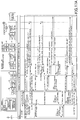
- FIG. 4 is a drawing illustrating an example of a hardware configuration of the image forming apparatus 10a.
- the image forming apparatus 10a includes a controller 910, a near-field-communication circuit 920, an engine controller 930, an operations panel 940, and a network I/F 950.
- the controller 910 includes a CPU 901 that is a main component of a computer, a system memory (MEM-P) 902, a north bridge (NB) 903, a south bridge (SB) 904, an application specific integrated circuit (ASIC) 906, a local memory (MEM-C) 907 that is a storage, an HDD controller 908, an HD 909 that is a storage, and an accelerated graphics port (AGP) bus 921 connecting the NB 903 to the ASIC 906.
- MEM-P system memory
- NB north bridge
- SB south bridge
- ASIC application specific integrated circuit
- MEM-C local memory
- HDD controller 908 an HD 909 that is a storage
- AGP accelerated graphics port
- the CPU 901 is a controller that controls the entire image forming apparatus 10a.
- the NB 903 is a bridge for connecting the CPU 901, the MEM-P 902, the SB 904, and the AGP bus 921 to each other, and includes a memory controller for controlling reading and writing of data from and to the MEM-P 902, a peripheral component interconnect (PCI) master, and an AGP target.
- PCI peripheral component interconnect
- the MEM-P 902 includes a ROM 902a that is a memory for storing programs and data for implementing functions of the controller 910, and a RAM 902b that is used, for example, to load programs and data and as a drawing memory for memory printing.
- the programs stored in the RAM 902b may be provided as installable or executable files recorded in a computer-readable recording medium such as a CD-ROM, a CD-R, or a DVD.
- the SB 904 is a bridge for connecting the NB903 to PCI devices and peripheral devices.
- the ASIC 906 is an integrated circuit (IC) for image processing and includes hardware components for image processing.
- the ASIC 906 functions as a bridge that connects the AGP bus 921, the PCI bus 922, the HDD controller 908, and the MEM-C 907 to each other.
- the ASIC 906 includes a PCI target, an AGP master, an arbiter (ARB) that is the core of the ASIC 906, a memory controller that controls the MEM-C 907, multiple direct memory access controllers (DMAC) that, for example, rotate image data using hardware logic, and a PCI unit that performs data transfer between a scanner 931 and a printer 932 via the PCI bus 922.
- a universal serial bus (USB) interface and/or an IEEE1394 (Institute of Electrical and Electronics Engineers 1394) interface may be connected to the ASIC 906.
- the MEM-C 907 is a local memory used as a copy image buffer and a code buffer.
- the HD 909 is a storage for storing image data, font data used for printing, and forms.
- the HDD controller 908 controls reading and writing of data from and to the HD 909 under the control of the CPU 901.
- the AGP bus 921 is a bus interface for a graphics accelerator card proposed to speed up graphics processing.
- the AGP bus 921 enables direct access to the MEM-P 902 at high throughput, and can increase the speed of the graphics accelerator card.
- the near-field-communication circuit 920 is provided with a near-field-communication circuit antenna 920a.
- the near-field-communication circuit 920 is, for example, a communication circuit for NFC or Bluetooth (registered trademark).
- the engine controller 930 includes the scanner 931 and the printer 932.
- the operations panel 940 includes a panel display 940a such as a touch panel that displays, for example, current settings and a selection screen and receives inputs from an operator, and hardware keys 940b including a numeric keypad for receiving settings of conditions related to image forming such as density settings and a start key for receiving a copy start instruction.
- the controller 910 controls the entire image forming apparatus 10a, and controls, for example, drawing, communications, and inputs from the operations panel 940.
- Each of the scanner 931 and the printer 932 includes an image processor for error diffusion and gamma conversion.
- An application switching key of the operations panel 940 enables sequentially switching and selecting a document box function, a copy function, a printer function, and a facsimile function of the image forming apparatus 10a.
- the image forming apparatus 10a transitions to a document box mode when the document box function is selected, to a copy mode when the copy function is selected, to a printer mode when the printer function is selected, and to a facsimile mode when the facsimile function is selected.
- the network I/F 950 is an interface for data communications via the network N1/N2.
- the near-field-communication circuit 920 and the network I/F 950 are electrically connected to the ASIC 906 via the PCI bus 922.
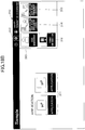
- FIG. 5 is a block diagram illustrating an example of functional configurations of the first terminal 20, the second terminal 30, the electronic apparatus 10, and the information processing system 50.
- the first terminal 20 includes a first communication unit 22, a display controller 23, an operation receiver 24, and a process controller 25.
- the first terminal 20 implements functional blocks as illustrated in FIG. 5 by executing a program (e.g., a web browser 21).
- the first communication unit 22 communicates with the information processing system 50 to send and receive various types of information that enable the first terminal 20 to display an appropriate login screen.
- the display controller 23 analyzes screen information received from the information processing system 50 and displays, for example, a login screen on the display 506.
- the operation receiver 24 receives a user operation on the first terminal 20 (for example, an input of account information on the login screen).
- the process controller 25 stores a login method used by the user and determines a login screen corresponding to a previously-used login method.
- the process controller 25 also controls subsequent processes depending on whether a login method is stored.
- the process controller 25 is implemented by executing JavaScript (registered trademark) included in screen information by an engine of the web browser 21.
- the first terminal 20 includes a browser information storage 26 used by a program (for example, the web browser 21) to store information.
- the browser information storage 26 (an example of an information storage) is formed in, for example, the HD 504 and is a non-volatile memory that retains information even when the web browser 21 is terminated.
- a function called LocalStorage, which is implemented by HTML5, may be used as an internal storage area of the terminal that can be managed by the web browser 21.
- one of login methods as listed in Table 1 is stored in the browser information storage 26.
- the browser information storage 26 may be provided outside of the first terminal 20 (for example, on a network or in a storage medium).
- Stored login method multiple methods may be stored) Flag value email address + password email tenant ID + user ID + password userId external service external all all
- Table 1 indicates examples of login methods that can be stored in the browser information storage 26.
- the login methods (A) through (D) described above are indicated by flags.
- the process controller 25 can determine the stored login method by reading the flag.
- the first terminal 20 displays a login screen corresponding to the login method using an email address and a password.
- the flag is "userld”
- the first terminal 20 displays a login screen corresponding to the login method using a tenant ID, a user ID, and a password.
- the flag is "external”
- the first terminal 20 displays a login screen corresponding to the login method using an external service.
- the flag is "all”
- the first terminal 20 displays a login screen corresponding to all login methods.
- the second terminal 30 includes a second communication unit 32, a display controller 33, an operation receiver 34, and a process controller 35.
- the second terminal 30 executes a program (e.g., a web browser 31) to implement functional blocks as illustrated in FIG. 5 .
- the second communication unit 32 communicates with the information processing system 50 to send and receive various types of information that enable the second terminal 30 to display an appropriate login screen.
- the display controller 33 analyzes screen information received from the information processing system 50 and displays, for example, a login screen on the display 506.
- the operation receiver 24 receives an operation (for example, an input of account information on the login screen) of the administrator on the second terminal 30.
- the process controller 35 stores a login method used by the administrator and determines a login screen corresponding to the previously-used login method.
- the process controller 35 also controls subsequent processes depending on whether a login method is stored.
- the process controller 35 is implemented by executing JavaScript (registered trademark) included in screen information by an engine of the web browser 31.
- the browser information storage 36 is substantially the same as the browser information storage 26 of the first terminal 20, and therefore descriptions of the browser information storage 36 are omitted.
- the electronic apparatus 10 includes a third communication unit 12, a display controller 13, an operation receiver 14, and a process controller 15.
- the electronic apparatus 10 implements functional blocks as illustrated in FIG. 5 by executing a program (for example, a web browser 11).
- the third communication unit 12 communicates with the information processing system 50 to receive screen information used by the electronic apparatus 10 to display, for example, a standby screen, a launcher screen, a login screen, and an application screen. Also, the third communication unit 12 sends information input by the user on the standby screen, the launcher screen, the login screen, and the application screen to the information processing system 50.
- the display controller 13 analyzes screen information received from the information processing system 50 and displays, for example, a standby screen, a launcher screen, a login screen, and an application screen on the operations panel 940.
- the operation receiver 14 receives user operations on the electronic apparatus 10 (for example, starting a launcher, inputting account information, selecting an application, and operating an application).
- the process controller 15 and the browser information storage 16 are substantially the same as the process controller 25 and the browser information storage 26 of the first terminal 20.
- the electronic apparatus 10 is shared by multiple users. Therefore, the electronic apparatus 10 may be configured to send user information (manually-input user ID and password, or information obtained from an IC card or an authentication device), which is input to the electronic apparatus 10 at the time of device authentication when the user starts using the electronic apparatus 10, and a device authentication result to the information processing system 50 by using the web browser 11 or another application of the electronic apparatus 10 to identify a tenant corresponding to the user information, and display a login screen corresponding to a login method permitted by the tenant.
- user information manually-input user ID and password, or information obtained from an IC card or an authentication device
- the web browser 11 or another application of the electronic apparatus 10 may obtain device identification information (device number) or tenant identification information stored in the electronic apparatus 10 and send the device identification information or the tenant identification information to the information processing system 50 to identify a tenant corresponding to the electronic apparatus 10.
- device identification information device number
- tenant identification information tenant identification information stored in the electronic apparatus 10
- tenant identification information tenant identification information stored in the electronic apparatus 10
- tenant identification information tenant identification information stored in the electronic apparatus 10
- user information processing system 50 it is assumed that the tenant identification information, the device identification information, and the user information are stored in association with each other in the information processing system 50.
- the information processing system 50 includes a fourth communication unit 52, a screen information generator 53, a user information manager 54, a tenant information manager 55, and an authentication-permission unit 56. These functions of the information processing system 50 are implemented by executing a program loaded from the HD 504 into the RAM 503 by the CPU 501 of the computer 500 illustrated in FIG. 3 .
- the fourth communication unit 52 sends and receives various types of information to and from the first terminal 20, the second terminal 30, and the electronic apparatus 10. For example, the fourth communication unit 52 sends screen information of a login screen to the first terminal 20 or the second terminal 30, and receives account information from the first terminal 20 or the second terminal 30. Also, the fourth communication unit 52 sends screen information of a standby screen, a launcher screen, a login screen, and an application screen to the electronic apparatus 10, and receives information input on these screens.
- the screen information generator 53 generates screen information of a login screen and a top screen (portal screen) and sends the screen information to the first terminal 20 or the second terminal 30 via the fourth communication unit 52.
- the user information manager 54 manages the generation, updating, acquisition, and deletion of user information in the user information storage 57.
- the tenant information manager 55 similarly manages information on tenants to which users belong in the tenant information storage 58. Users and tenants are associated with each other by the user information and the tenant information.
- the authentication-permission unit 56 authenticates the administrator and the users based on the account information and determines whether the authentication is successful or failed.
- authentication indicates determining whether a user is a valid user.
- the authentication-permission unit 56 determines whether a user has a right to use the information processing system 50 and can also determine whether the user is a general user or an administrator.
- permission indicates determining rights permitted to a user according to the user role (described later). For example, accessible resources and executable operations are determined.
- Login is an authentication process performed to access system resources to use various services on a computer or the Internet by using pre-registered account information.
- Account information varies depending on the login methods (A) through (D) described above.
- account information includes an email address and a password.
- tenant ID, user ID and password account information includes a tenant ID, a user ID, and a password.
- tenant ID, user ID and password account information includes a tenant ID, a user ID, and a password.
- (C) Using external service there is no account information to be input by the user, but a user ID and a password for the external service 70 serve as account information.
- account information corresponding to each login method is used.
- account information may be biometric authentication information such as a fingerprint and a face.
- biometric authentication information such as a fingerprint and a face.
- a login method corresponding to the biometric authentication information is provided.
- the information processing system 50 also includes the user information storage 57 and the tenant information storage 58 that are implemented by, for example, the HD 504 or the RAM 503 illustrated in FIG. 3 .
- the user information storage 57 and the tenant information storage 58 are described below using Tables 2, 3A, and 3B.
- Table 2 indicates an example of user information stored in the user information storage 57.
- Table 3A indicates an example of tenant information stored in the tenant information storage 58.
- Table 3B indicates examples of login settings. As indicated in Table 3B, each login setting is represented by a flag and indicates a login method(s) that a tenant permits users belonging to the tenant to use. Because the flag is sent from the information processing system 50 to the first terminal 20 or the second terminal 30, the first terminal 20 or the second terminal 30 can determine a login method permitted by the tenant (for the user).
- FIG. 6 is an example of a login method setting screen 400 displayed by the second terminal 30 being operated by the administrator.
- check boxes 401 are associated with "all", "email address + password”, "tenant ID + user ID + password”, and "external service”.
- the administrator can set a login method for each tenant that the administrator manages.
- FIGs. 7A and 7B are sequence charts illustrating a process where the user operates the first terminal 20 to display a login screen.
- the first terminal 20 can display a login screen corresponding to a stored login method.
- FIG. 8 is an example of an email address input screen 410 that is a part of a login screen.
- the email address input screen 410 includes an email address input field 411 and a next button 412.
- the email address input field 411 is a field in which the user inputs an email address of the user.
- the next button 412 causes the first terminal 20 to send the input email address to the information processing system 50.
- FIG. 9 illustrates an example of the login screen A1.
- the login screen A1 includes an email address display field 421, a password input field 422, and a login button 423.
- the email address display field 421 displays the email address entered by the user on the email address input screen 410. This eliminates the need to enter the same email address multiple times. The user can also return to the email address input screen 410.
- the password input field 422 is a field in which the user inputs a password of the user.
- the login button 423 causes the first terminal 20 to send the email address and the password to the information processing system 50 to make a login request.
- FIG. 10 illustrates an example of the login screen B1.
- the login screen B1 includes an email address display field 421, a tenant ID input field 424, a user ID input field 425, a password input field 422, and a login button 423.
- the email address display field 421 displays the email address entered by the user on the email address input screen. This eliminates the need to enter the same email address multiple times (the email address is not necessarily sent to the information processing system 50). The user can also return to the email address input screen 410.
- the tenant ID input field 424 is a field in which the user inputs a tenant ID of a tenant to which the user belongs.
- the user ID input field 425 is a field in which the user inputs a user ID used in the tenant to which the user belongs.
- the password input field 422 is a field in which the user inputs a password of the user.
- the login button 423 causes the first terminal 20 to send the tenant ID, the user ID, and the password to the information processing system 50 to make a login
- FIG. 11 illustrates an example of the login screen C1.
- the login screen C1 includes an email address display field 421 and an external service login button 426.
- the email address display field 421 displays the email address entered by the user on the email address input screen 410. This eliminates the need to enter the same email address multiple times (the email address is not necessarily sent to the information processing system 50).
- the external service login button 426 causes the first terminal 20 to send a request for login using the external service 70 to the information processing system 50. After sending the request, the first terminal 20 is redirected to the external service 70.
- FIG. 12 illustrates an example of the login screen D1.
- the login screen D1 includes an email address input field 411, a password input field 422, a login button 423, a user ID login button 431, and an external service login button 426.
- the email address input field 411 the email address entered by the user on the email address input screen 410 is displayed. This eliminates the need to enter the same email address multiple times.
- the password input field 422 is a field in which the user inputs a password of the user.
- the login button 423 causes the first terminal 20 to send the email address and the password to the information processing system 50 to make a login request.
- the user ID login button 431 is for displaying the login screen B1 of FIG. 10 .
- the external service login button 426 causes the first terminal 20 to send a request for login using the external service 70 to the information processing system 50.
- the login method is "all"
- the user can change the login screens.
- FIG. 13 illustrates an example of the login screen A2.
- the login screen A2 includes an email address input field 411, a password input field 422, a login button 423, and a "check other login method" button 432.
- the email address input field 411 is a field in which the user inputs an email address of the user.
- a login method is stored in the browser information storage 26
- the user has not entered an email address. Accordingly, no email address is displayed in the email address input field 411.
- the password input field 422 and the login button 423 are the same as those in the login screen A1.
- the "check other login method" button 432 allows the user to check a login method(s) (a login method permitted by the tenant) that is different from the login method stored in the browser information storage 26.
- FIG. 14 illustrates an example of the login screen B2.
- the login screen B2 includes a tenant ID input field 424, a user ID input field 425, a password input field 422, a login button 423, and a "check other login method” button 432. These items are the same as those in the login screen B1.
- the "check other login method” button 432 is the same as that in the login screen A2.
- FIG. 15 illustrates an example of the login screen C2.
- the login screen C2 includes an external service login button 426 and a "check other login method" button 432.
- the external service login button 426 is the same as that in the login screen C1.
- the "check other login method” button 432 is the same as that in the login screen A2.
- FIG. 16 is an example of a login screen F that is displayed when multiple login methods are permitted.
- the login screen F corresponds to a case where the login methods "(A) Email address and password" and "(C) Using external service” are permitted. Accordingly, the login screen F includes an email address input field 411, a password input field 422, and an external service login button 426.
- the first terminal 20 can display login screens corresponding to the multiple login methods, and the user can select a preferred login method.
- FIGs. 17A and 17B are sequence charts illustrating login processes corresponding to the respective login methods. The processes of FIGs. 17A and 17B are performed after the process of FIG. 7 .
- S1, S2 The user inputs a password on the login screen A1, inputs a tenant ID, a user ID, and a password on the login screen B1, inputs an email address and a password on the login screen A2, or inputs a tenant ID, a user ID, and a password on the login screen B2.
- the operation receiver 24 receives these inputs as account information.
- the operation receiver 24 of the first terminal 20 sends the account information to the process controller 25 and requests a login process.
- Steps S3 through S8 are performed when the login method is "(A) Email address and password” or "(B) Tenant ID, user ID, and password”.
- the process controller 25 sends an authentication request together with the account information to the information processing system 50.
- the account information and the authentication request are transmitted to the authentication-permission unit 56 via the first communication unit 22 and the fourth communication unit 52.
- the authentication-permission unit 56 determines that the authentication has succeeded if the account information is stored in the user information storage 57, and determines that the authentication has failed if the account information is not stored in the user information storage 57.
- the authentication-permission unit 56 sends information indicating that the authentication has succeeded to the first terminal 20.
- authentication information is used to indicate that the authentication has succeeded.
- Steps S9 through S38 are performed when the login method is "(C) Using external service". Similarly, at step S9, the process controller 25 temporarily stores the login method used by the user. Alternatively, the login method may be stored at step S38.
- S9, S10 The user presses the external service login button 426 on the login screen C1 or C2.
- the operation receiver 24 receives the pressing operation.
- a request for login with the external service 70 is sent to the authentication-permission unit 56 via the first communication unit 22 and the fourth communication unit 52.
- S11-S14 Upon receiving information indicating that the external service login button 426 has been pressed, the authentication-permission unit 56 sends a redirection request for redirection to the external service 70 to the first terminal 20 together with the known URL of the external service 70.
- the URL of the external service 70 and the redirection request to the external service 70 are sent to the process controller 25 via the first communication unit 22 and the fourth communication unit 52.
- Common tickets for identifying users are stored in advance in each of the information processing system 50 and the external service 70.
- the process controller 25 is redirected to the external service 70 based on the URL of the external service 70. That is, the process controller 25 is redirected to the external service 70 and obtains screen information of a login screen of the external service 70.
- the login screen of the external service 70 varies depending on the type of the external service 70.
- the process controller 25 sends the screen information of the login screen of the external service 70 to the display controller 23, and the display controller 23 displays the login screen of the external service 70.
- S23 The user performs a login operation on the login screen of the external service 70.
- the operation receiver 24 receives the login operation.
- account information is stored using a technology such as a cookie or LocalStorage, and the user does not need to enter account information on the login screen of the external service 70. Therefore, when the user uses the external service 70, the user only needs to press the external service login button 426.
- the operation receiver 24 sends pre-stored account information and an authentication request to the external service 70 via the process controller 25, the first communication unit 22 and the fourth communication unit 52.
- the external service 70 authenticates the user and when the authentication is successful, obtains a ticket associated with the user.
- the ticket is the proof of the identity of the user.
- An authentication linkage service such as OAUTH is known as a mechanism for such external authentication, and it is assumed that OAUTH can be used in the present embodiment.
- the external service 70 sends the ticket to the first terminal 20.
- the ticket is represented by authentication information.
- the process controller 25 requests the authentication-permission unit 56 to perform authentication using the ticket (authentication information) received from the external service 70.
- the authentication request is sent to the authentication-permission unit 56 via the first communication unit 22 and the fourth communication unit 52.
- the authentication-permission unit 56 requests the external service 70 to verify the authentication information (to confirm that the authentication information has been issued by the external service 70).
- the authentication information is successfully verified by the external service 70, the login to the information processing system 50 is permitted. Also, the user is identified by the ticket.
- the authentication-permission unit 56 sends authentication information indicating whether authentication has succeeded to the first terminal 20.
- the authentication information is transmitted to the process controller 25 via the first communication unit 22 and the fourth communication unit 52.
- the process controller 25 sends a permission request to the information processing system 50.
- permission indicates a range of resources that a user can access (i.e., rights of the user).
- the process controller 25 sends a permission request to the information processing system 50 together with the authentication information.
- the permission request is sent to the authentication-permission unit 56 via the first communication unit 22 and the fourth communication unit 52.
- the authentication-permission unit 56 For a user using the login method (A) or (B), the authentication-permission unit 56 sends a role of user information and an available service right information list to the first terminal 20 as a range of resources that can be accessed by a user identified by an email address or a user ID and a tenant ID. For a user using the login method (C), the authentication-permission unit 56 identifies the user based on the ticket, issues a token (identification information for identifying the user), and sends similar information to the first terminal 20.
- the role of user information and the available service right information list are referred to as "permission information”.
- the process controller 25 Upon receiving the permission information, the process controller 25 sends, to the information processing system 50, user identification information (an email address, a user ID and a tenant ID, or a token) and a request for a login setting of a tenant to which the user belongs.
- the permission information is sent to report information that the user can access.
- the login setting request is sent to the information processing system 50 via the first communication unit 22 and the fourth communication unit 52.
- the user information manager 54 obtains user information from the user information storage 57 of the user identified based on the user identification information.
- the user information manager 54 sends the user information to the tenant information manager 55, and the tenant information manager 55 searches the tenant information storage 58 with a tenant ID included in the user information. Thus, the tenant information manager 55 obtains tenant information of a tenant to which the user belongs.
- the information processing system 50 sends a login setting included in the tenant information to the first terminal 20.
- the process controller 25 determines whether the login setting used by the user is permitted by the login setting of the tenant. This is because the process controller 25 preferably changes the login method of the user when the login setting of the tenant is changed. The process controller 25 may determine whether the login setting used by the user is included in the login setting of the tenant. A case where the login setting used by the user is not included in the login setting of the tenant occurs when a login method stored in the browser information storage 26 is used. Accordingly, this is the same as determining whether a login method stored in the browser information storage 26 is included in the login setting of the tenant.
- the process controller 25 stores the login setting of the tenant in the browser information storage 26. When there are multiple tenant login settings, all of the login settings may be stored.
- the process controller 25 stores the login method temporarily stored at step S3, S8, S9, or S38 in the browser information storage 26.
- the process controller 25 sends a request for a top screen (portal screen) to the information processing system 50.
- the screen information generator 53 of the information processing system 50 refers to the user information storage 57, generates screen information including icons for executing services permitted for the user identified based on the user identification information, and sends the screen information to the first terminal 20.
- a portal screen corresponding to the logged-in user can be displayed.
- FIGs. 18A and 18B illustrate examples of top screens.
- FIG. 18A is an example of a top screen 460 displayed by the first terminal 20
- FIG. 18B is an example of a top screen 310 displayed by the second terminal 30.
- the first terminal 20 displays the top screen 460.
- the top screen 460 displays a list 311 of applications corresponding to services permitted by the "available service right information list" in the user information.
- the top screen 310 for the administrator has a similar configuration but additionally includes a setting button 312.
- buttons for user management 313, application use right management (user) 314, application use right management (device) 315, and tenant information 316 are displayed.
- the user management 313 is a button for displaying a user management screen used by the administrator to manage users.
- the application use right management (user) 314 is a button for displaying a screen for managing applications that the users can use.
- the application use right management (device) 315 is a button for displaying a screen for managing applications that the electronic apparatuses 10 can use.
- the tenant information 316 is a button for displaying a screen for displaying contract (subscription) information of the tenant.
- each of the login screens A2, B2, and C2 includes the "check other login method” button 432.
- a process performed when the "check other login method" button 432 is pressed is described below.
- FIG. 19 is a sequence chart illustrating an example of a process performed by the first terminal 20 and the information processing system 50 when the "check other login method" button 432 is pressed.
- the process of FIG. 19 starts after a login screen is displayed at step S31, S33, or S35 in FIG. 7 .
- the user can check another login method (or other login methods) and can log in with a login method different from the login method stored in the browser information storage 26.
- the login method is stored in the browser information storage 26, and the login method for the next time can be changed.
- FIG. 19 it is assumed that one login method is displayed each time ( FIGs. 9 through 11 ). However, when multiple login methods are permitted, the login screen F corresponding to multiple login methods is displayed as illustrated in FIG. 16 .
- the first terminal 20 or the second terminal 30 can display a login screen corresponding to the login method permitted by the tenant without requiring the user to input information such as an email address for identifying the user. Also, even when a service of an information processing system provides multiple selectable login methods for each tenant, to present an appropriate login screen to the user, it is necessary to identify a tenant to which the user belongs based on identification information of the user. However, with the present embodiment, once a login method is stored, the user does not have to enter identification information (e.g., an email address) of the user each time.
- identification information e.g., an email address
- the present embodiment can eliminate the need for the user to input the dentification information of the user for the service provided by the information processing system 50.
- a login method used by the user when a login method used by the user is not permitted by the login setting of the tenant, a login method permitted by the login setting of the tenant is stored in the browser information storage 26. Therefore, the login is allowed, and the login screen is changed from the next login.
- the information processing system 50 when a login method used by the user is not permitted by the login setting of the tenant, the information processing system 50 causes the user to log out and to log in with a login method permitted by the login setting of the tenant.
- FIGs. 20A and 20B are sequence charts illustrating a process where the information processing system 50 causes the user to log out when a login method used by the user is not permitted by the login setting of the tenant and to log in with a login method permitted by the tenant.
- step S1 and S2 The user logs in. After step S2 and before step S3, steps up to step S54 of FIGs. 17A and 17B are performed. The process described below is performed in place of steps S55 through S58 of FIG. 17B .
- the process controller 25 sends a logout process request together with user identification information (for example, an email address, a tenant ID and a user ID, or a token) to the information processing system 50.
- the first communication unit 22 and the fourth communication unit 52 send the logout process request to the authentication-permission unit 56.
- the authentication-permission unit 56 causes the user identified by the user identification information to log out. That is, the authentication-permission unit 56 deletes permission information given to the user.
- the authentication-permission unit 56 sends information indicating that the permission information has been deleted to the first terminal 20.
- the first communication unit 22 and the fourth communication unit 52 send the information indicating that the permission information has been deleted to the process controller 25.
- the process controller 25 sends a request for a logout screen to the information processing system 50 and obtains screen information of the logout screen to report to the user that the user has been logged out.
- the process controller 25 sends the screen information of the logout screen to the display controller 23, and the display controller 23 displays the logout screen.
- FIG. 21 illustrates an example of the logout screen.
- the logout screen enables the user to know that the user has been logged out. Also, because the logout screen prompts the user to log in again with a login method permitted by the tenant, the user can log in with the login method permitted by the tenant.
- steps S19 through S28 performed when the login method used by the user is permitted by the login setting of the tenant may be the same as steps S57 through S66 of FIG. 17B .
- FIG. 21 is a drawing illustrating an example of a logout screen 470.
- the logout screen 470 displays a message 471 "YOU HAVE BEEN LOGGED OUT BECAUSE LOGIN METHOD HAS BEEN CHANGED BY ADMINISTRATOR. LOG IN AGAIN".
- a "log in” button 472 When the user presses a "log in” button 472, the logout screen 470 is switched to a login screen.
- the information processing system 50 when the login method used by the user is not permitted by the login setting of the tenant, the information processing system 50 causes the user to log out. This makes it possible to strictly apply the login setting of the tenant and let the user log in with a login method permitted by the tenant.
- the administrator of a tenant can change the login setting of the tenant, only the administrator may be allowed to log in using various login methods regardless of the login setting of the tenant.
- all login screens that can be set by the administrator in the information processing system 50 are displayed.
- FIG. 22 is a sequence chart illustrating an example of a process in which the first terminal 20 changes a login screen to be displayed according to the login setting of the tenant and the role of the user.
- the process controller 25 determines a login screen according to the login method permitted in the login setting and the role of the user.
- the display controller 23 displays a login screen E1 corresponding to all login methods.
- FIG. 23 illustrates an example of the login screen E1.
- FIGs. 22A and 22B one login screen is displayed for each login method ( FIGs. 9 through 11 ). However, when multiple login methods are permitted, the login screen F corresponding to the multiple login methods is displayed as illustrated in FIG. 16 .
- FIG. 23 illustrates an example of the login screen E1.
- the login screen E1 corresponds to all login methods and is therefore similar to the login screen D1 of FIG. 12 .
- the administrator can login with a preferred login method.
- the user can check whether there is another login method (or other login methods) permitted by the tenant. That is, when the user role is an administrator, the second terminal 30 can display the login screen E1.
- FIG. 24 is a sequence chart illustrating an example of a process performed by the second terminal 30 and the information processing system 50 when the "check other login method" button 432 is pressed. Below, differences between FIG. 24 and FIG. 19 are mainly described. The user presses the "check other login method" button 432 on the login screen A2, B2, or C2.
- S1-S16 These steps are substantially the same as steps S1 through S16 of FIG. 19 except that the role of the user is sent to the second terminal 30.
- the user information manager 54 obtains the role of the user identified based on the email address from the user information storage 57.
- the login setting of the tenant and the role of the user are sent to the process controller 35.
- the process controller 35 determines a login screen according to the login method permitted by the login setting and the role of the user.
- the process controller 35 may store all login methods. Once all login methods have been stored, the administrator can log in from the login screen E1 corresponding to all login methods without entering the email address.
- FIGs. 25A and 25B are sequence charts illustrating an example of a process where the second terminal 30 stores all login methods when the logged-in user is the administrator.
- Steps S1 through S44 are substantially the same as steps S1 through S44 of FIGs. 17A and 17B . Also, steps S45 through S53 are substantially the same as steps S6 through S16 of FIG. 24 .
- S54 The process controller 35 receives the login setting of the tenant and the role of the user.
- Steps S61 through S67 may be substantially the same as steps S59 through S66 of FIG. 17B .
- the administrator can log in from the login screen E1 corresponding to all login methods without entering the email address.
- the third embodiment makes it possible to display all login screens when the administrator logs in and thereby makes it possible to improve the operability by the administrator.
- the user logs in with a login method that is stored in the browser information storage 26 but is not permitted by the login setting of the tenant.
- the login method permitted by the login setting of the tenant is stored in the browser information storage 26.
- the user may not have registered account information used for the login setting of the tenant.
- this login method becomes not permitted by the login setting of the tenant, a password is necessary for another login method, but no password is registered in the user information.
- the user logged in with a login method using a password this login method becomes not permitted by the login setting of the tenant, a linkage with the external service 70 is necessary for another login method, but the external service 70 is not registered in the user information.
- a fourth embodiment describes a computer system 1 where the user can add account information necessary for a login method permitted by the login setting of the tenant.
- FIGs. 26A and 26B are sequence charts illustrating an example of a process where the user adds account information necessary for a login method permitted by the login setting of the tenant when the user logged in with a login method that is stored in the browser information storage 26 but is not permitted by the login setting of the tenant.
- step S1, S2 The user logs in. After step S2 and before step S3, steps up to step S54 of FIGs. 17A and 17B are performed.
- the process controller 25 sends a request for user information to the information processing system 50 together with user identification information (an email address, a tenant ID and a user ID, or a token). This is to determine whether a password has been set and whether the user is linked with the external service 70.
- the first communication unit 22 and the fourth communication unit 52 send the request for user information to the user information manager 54.
- the user information manager 54 obtains user information identified based on the user identification information from the user information storage 57.
- the user information manager 54 sends the user information to the first terminal 20.
- the first communication unit 22 and the fourth communication unit 52 send the user information to the process controller 25.
- Steps S13 through S30 are performed when the login method "(A) Email address and password” or "(B) Tenant ID, user ID, and password” is permitted but no password is registered.
- the process controller 25 sends a request for a password setting screen to the information processing system 50.
- the first communication unit 22 and the fourth communication unit 52 send the request for a password setting screen to the screen information generator 53.
- the screen information generator 53 generates screen information of the password setting screen and sends the screen information to the first terminal 20.
- the first communication unit 22 and the fourth communication unit 52 send the screen information of the password setting screen to the process controller 25.
- the process controller 25 sends the screen information of the password setting screen to the display controller 23.
- the display controller 23 displays the password setting screen.
- FIG. 27 illustrates an example of the password setting screen.
- S21 The user inputs a password.
- the operation receiver 24 receives the input password.
- the process controller 25 sends a password registration request to the information processing system 50 together with user identification information.
- the first communication unit 22 and the fourth communication unit 52 send the password registration request to the user information manager 54.
- the user information manager 54 identifies the user with the user identification information (an email address, a tenant ID and a user ID, or a token), and registers the password in the user information.
- the user information manager 54 sends a password registration completion report to the first terminal 20.
- the first communication unit 22 and the fourth communication unit 52 send the password registration completion report to the process controller 25.
- Steps S31 through S64 are performed when the login method "(C) Using external service” is permitted but the external service 70 is not registered.
- the process controller 25 sends a request for an external service authentication linkage screen to the information processing system 50.
- the request for the external service authentication linkage screen is transmitted to the screen information generator 53 via the first communication unit 22 and the fourth communication unit 52.
- the screen information generator 53 generates screen information of the external service authentication linkage screen and sends the screen information to the first terminal 20.
- the screen information of the external service authentication linkage screen is transmitted to the process controller 25 via the first communication unit 22 and the fourth communication unit 52.
- the process controller 25 sends the screen information of the external service authentication linkage screen to the display controller 23.
- FIG. 28 illustrates an example of the external service authentication linkage screen.
- the operation receiver 24 sends information indicating that the authentication linkage button is pressed, to the process controller 25.
- the process controller 25 requests the information processing system 50 to perform an external service authentication linkage process.
- the request for the external service authentication linkage process is transmitted to the authentication-permission unit 56 via the first communication unit 22 and the fourth communication unit 52.
- the authentication-permission unit 56 Upon receiving the request for the external service authentication linkage process, the authentication-permission unit 56 sends a redirection request for redirection to the external service 70 to the first terminal 20 together with a known URL of the authentication linkage screen of the external service 70.
- the URL of the authentication linkage screen of the external service 70 and the redirection request to the external service 70 are sent to the process controller 25 via the first communication unit 22 and the fourth communication unit 52.
- the authentication-permission unit 56 sends a ticket for identifying the user to the first terminal 20.
- the process controller 25 is redirected to the authentication linkage screen of the external service 70 based on the URL of the authentication linkage screen of the external service 70. That is, the process controller 25 is redirected to the external service 70 and obtains screen information of the authentication linkage screen of the external service 70.
- the process controller 25 sends the screen information of the authentication linkage screen of the external service 70 to the display controller 23, and the display controller 23 displays the authentication linkage screen of the external service 70.
- S53 The user activates authentication linkage with the external service 70 on the authentication linkage screen of the external service 70.
- the operation receiver 24 receives the operation.
- account information is stored using a technology such as a cookie, and the user does not need to input account information to the external service 70. Therefore, when the user uses the external service 70, the user only needs to press the external service login button 426.
- the operation receiver 24 sends the account information stored using, for example, a cookie, an authentication request, a ticket, and a request to activate the authentication linkage with the external service 70 to the external service 70 via the process controller 25, the first communication unit 22, and the fourth communication unit 52.
- the external service 70 authenticates the user and when the authentication is successful, enables the authentication linkage for the user identified by user identification information.
- S57, S58 The external service 70 sends information indicating that the authentication linkage has been activated to the first terminal 20.
- the process controller 25 sends an authentication linkage registration request together with the ticket to the information processing system 50.
- the ticket and the authentication linkage registration request are transmitted to the authentication-permission unit 56 via the first communication unit 22 and the fourth communication unit 52.
- the authentication-permission unit 56 activates the authentication linkage for the user identified by the ticket and sends an authentication linkage information registration completion report (which indicates that the authentication linkage has been set) to the first terminal 20.
- the authentication linkage information registration completion report is transmitted to the process controller 25 via the first communication unit 22 and the fourth communication unit 52.
- Steps S65 through S74 may be substantially the same as steps S57 through S66 of FIG. 17B .
- FIG. 27 is an example of a password setting screen 480.
- the password setting screen 480 includes a password setting field 481 and a password confirmation field 482.
- the process controller 25 checks the number and the type of characters constituting a password and accepts the setting of the password when the password in the password setting field 481 and the password in the password confirmation field 482 are the same.
- FIG. 28 is an example of an external service authentication linkage screen 490.
- the external service authentication linkage screen 490 includes an authentication linkage button ("Register External Service”) 491.
- the authentication linkage button 491 activates authentication linkage with the external service 70.
- the user when the user logged in using a login method that is stored in the browser information storage 26 but is not permitted by the login setting of the tenant, the user can add account information necessary for a login method permitted by the login setting of the tenant.
- FIG. 5 The configurations illustrated in FIG. 5 are represented by process units or functional blocks to facilitate the understanding of processes performed by the first terminal 20, the second terminal 30, the electronic apparatus 10, and the information processing system 50.
- the present invention is not limited by a manner in which each apparatus is divided into process units and the names of the process units.
- the process units of each of the first terminal 20, the second terminal 30, the electronic apparatus 10, and the information processing system 50 may be further divided into a greater number of process units depending on processes to be performed.
- each apparatus may be divided into process units such that each process unit includes a greater number of processes.
- the apparatuses described above merely indicate one of multiple computing environments for implementing the embodiments described in the present application.
- the information processing system 50 may include multiple computing devices such as server clusters.
- the multiple computing devices may be configured to communicate with each other via a communication link such as a network or a shared memory and perform processes disclosed in the present application.
- the information processing system 50 may be configured to share the steps illustrated in, for example, FIGs. 7A and 7B , FIGs. 17A and 17B , FIG. 19 , FIGs. 20A and 20B , FIGs. 22A and 22B , FIG. 24 , FIGs. 25A and 25B , and FIGs. 26A and 26B in various combinations.
- a process executed by a given unit may be executed by multiple information processing apparatuses included in the information processing system 50.
- the information processing system 50 may be implemented by one server or may be implemented by multiple apparatuses.
- processing circuit may indicate a processor that is implemented by an electronic circuit and programmed by software to implement various functions, or a device such as an application specific integrated circuit (ASIC), a digital signal processor (DSP), a field programmable gate array (FPGA), or a circuit module designed to implement various functions described above.
- ASIC application specific integrated circuit
- DSP digital signal processor
- FPGA field programmable gate array
- An aspect of this disclosure makes it possible to provide a computer system that can display an appropriate login screen without identifying a user.
Landscapes
- Engineering & Computer Science (AREA)
- Theoretical Computer Science (AREA)
- General Engineering & Computer Science (AREA)
- Computer Security & Cryptography (AREA)
- Physics & Mathematics (AREA)
- General Physics & Mathematics (AREA)
- Computer Hardware Design (AREA)
- Software Systems (AREA)
- Human Computer Interaction (AREA)
- Health & Medical Sciences (AREA)
- Bioethics (AREA)
- General Health & Medical Sciences (AREA)
- Signal Processing (AREA)
- Computer Networks & Wireless Communication (AREA)
- Computing Systems (AREA)
- Information Transfer Between Computers (AREA)
Applications Claiming Priority (1)
| Application Number | Priority Date | Filing Date | Title |
|---|---|---|---|
| JP2019167610A JP7322619B2 (ja) | 2019-09-13 | 2019-09-13 | コンピュータシステム、ログイン画面表示方法、プログラム |
Publications (2)
| Publication Number | Publication Date |
|---|---|
| EP3792793A1 true EP3792793A1 (fr) | 2021-03-17 |
| EP3792793B1 EP3792793B1 (fr) | 2024-05-15 |
Family
ID=72428156
Family Applications (1)
| Application Number | Title | Priority Date | Filing Date |
|---|---|---|---|
| EP20194855.1A Active EP3792793B1 (fr) | 2019-09-13 | 2020-09-07 | Système informatique, procédé d'affichage d'écran d'ouverture de session, et programme |
Country Status (3)
| Country | Link |
|---|---|
| US (1) | US11429327B2 (fr) |
| EP (1) | EP3792793B1 (fr) |
| JP (1) | JP7322619B2 (fr) |
Cited By (1)
| Publication number | Priority date | Publication date | Assignee | Title |
|---|---|---|---|---|
| US20210382981A1 (en) * | 2020-06-09 | 2021-12-09 | Ricoh Company, Ltd. | Service providing system, application usage method, and information processing system |
Families Citing this family (3)
| Publication number | Priority date | Publication date | Assignee | Title |
|---|---|---|---|---|
| JP2022098997A (ja) * | 2020-12-22 | 2022-07-04 | 富士フイルムビジネスイノベーション株式会社 | 画像形成装置、画像形成プログラム及び連携システム |
| US20230185893A1 (en) * | 2021-12-10 | 2023-06-15 | Konica Minolta Business Solutions U.S.A., Inc. | Method and system for secure cloud access via password-less single sign-on (sso) for native marketplace applications on multifunction printers |
| US20230195862A1 (en) * | 2022-02-16 | 2023-06-22 | IsItMe LLC | Methods and systems for facilitating authenticating of users |
Citations (3)
| Publication number | Priority date | Publication date | Assignee | Title |
|---|---|---|---|---|
| US20160065541A1 (en) * | 2014-08-28 | 2016-03-03 | Facebook, Inc. | Anonymous single sign-on to third-party systems |
| US20160127610A1 (en) * | 2014-10-31 | 2016-05-05 | Ricoh Company, Ltd. | Data processing system and data processing method |
| EP3256976A1 (fr) * | 2015-02-12 | 2017-12-20 | United Services Automobile Association (USAA) | Basculement d'authentification biométrique |
Family Cites Families (12)
| Publication number | Priority date | Publication date | Assignee | Title |
|---|---|---|---|---|
| GB2396037B (en) * | 2001-05-29 | 2005-08-24 | Xenobit Corp | Method and system for logging into and providing access to a computer system via a communications network |
| JP2004252862A (ja) * | 2003-02-21 | 2004-09-09 | Canon Inc | ログイン装置とその制御方法並びにデータ処理装置及び方法 |
| TW200910136A (en) * | 2007-08-24 | 2009-03-01 | Inventec Corp | Operation system logon method and electronic device using the same |
| JP5069820B2 (ja) * | 2010-03-16 | 2012-11-07 | 京セラドキュメントソリューションズ株式会社 | 画像形成システムおよびユーザマネージャサーバ装置 |
| KR20120087310A (ko) * | 2011-01-04 | 2012-08-07 | 삼성전자주식회사 | 휴대용 단말기에서 소셜 네트워크 서비스를 제공하기 위한 장치 및 방법 |
| JP6467869B2 (ja) * | 2013-11-05 | 2019-02-13 | 株式会社リコー | 情報処理システム及び情報処理方法 |
| JP6540063B2 (ja) * | 2015-02-05 | 2019-07-10 | 日本電気株式会社 | 通信情報制御装置、中継システム、通信情報制御方法、および、通信情報制御プログラム |
| CN104966007A (zh) * | 2015-05-28 | 2015-10-07 | 深圳市万普拉斯科技有限公司 | 多用户登录方法和装置 |
| JP6810334B2 (ja) * | 2016-06-17 | 2021-01-06 | 富士通株式会社 | プロファイルデータ配信制御装置、プロファイルデータ配信制御方法およびプロファイルデータ配信制御プログラム |
| US10970385B2 (en) * | 2017-06-04 | 2021-04-06 | Apple Inc. | Multiple device credential sharing |
| JP6984506B2 (ja) | 2018-03-16 | 2021-12-22 | 株式会社リコー | 情報処理システム、情報処理装置及びプログラム |
| US10698701B1 (en) * | 2019-06-01 | 2020-06-30 | Apple Inc. | User interface for accessing an account |
-
2019
- 2019-09-13 JP JP2019167610A patent/JP7322619B2/ja active Active
-
2020
- 2020-09-03 US US17/011,237 patent/US11429327B2/en active Active
- 2020-09-07 EP EP20194855.1A patent/EP3792793B1/fr active Active
Patent Citations (4)
| Publication number | Priority date | Publication date | Assignee | Title |
|---|---|---|---|---|
| US20160065541A1 (en) * | 2014-08-28 | 2016-03-03 | Facebook, Inc. | Anonymous single sign-on to third-party systems |
| US20160127610A1 (en) * | 2014-10-31 | 2016-05-05 | Ricoh Company, Ltd. | Data processing system and data processing method |
| JP6375877B2 (ja) | 2014-10-31 | 2018-08-22 | 株式会社リコー | 情報処理システム、情報処理方法、サービス利用装置、及びプログラム |
| EP3256976A1 (fr) * | 2015-02-12 | 2017-12-20 | United Services Automobile Association (USAA) | Basculement d'authentification biométrique |
Cited By (2)
| Publication number | Priority date | Publication date | Assignee | Title |
|---|---|---|---|---|
| US20210382981A1 (en) * | 2020-06-09 | 2021-12-09 | Ricoh Company, Ltd. | Service providing system, application usage method, and information processing system |
| US11995173B2 (en) * | 2020-06-09 | 2024-05-28 | Ricoh Company, Ltd. | Service providing system, application usage method, and information processing system |
Also Published As
| Publication number | Publication date |
|---|---|
| JP7322619B2 (ja) | 2023-08-08 |
| EP3792793B1 (fr) | 2024-05-15 |
| JP2021043902A (ja) | 2021-03-18 |
| US20210081154A1 (en) | 2021-03-18 |
| US11429327B2 (en) | 2022-08-30 |
Similar Documents
| Publication | Publication Date | Title |
|---|---|---|
| EP3792793B1 (fr) | Système informatique, procédé d'affichage d'écran d'ouverture de session, et programme | |
| US9288213B2 (en) | System and service providing apparatus | |
| US9514291B2 (en) | Information processing system, information processing device, and authentication information management method | |
| US11895108B2 (en) | Service providing system, login setting method, and information processing system | |
| US20210377277A1 (en) | Service providing system, information processing system, and use permission assigning method | |
| US9661184B2 (en) | Data processing system and data processing method for authenticating user by utilizing user list obtained from service providing apparatus | |
| JP2015127950A (ja) | 情報処理システム及び情報処理方法 | |
| EP3767497A1 (fr) | Système en nuage, système de traitement d'informations et procédé d'enregistrement d'utilisateur | |
| US11995173B2 (en) | Service providing system, application usage method, and information processing system | |
| JP7459649B2 (ja) | クラウドシステム、情報処理システム、ユーザ登録方法 | |
| EP3819796A1 (fr) | Au moins un appareil de traitement d'informations, système de traitement d'informations et procédé de désignation de rôle | |
| JP7484484B2 (ja) | サービス提供システム、及びグループ管理方法 | |
| JP7388222B2 (ja) | 情報処理システム、システム、利用制限方法 | |
| JP7222246B2 (ja) | サービスシステム、クラウドサービス、ユーザ登録方法、プログラム | |
| JP2017084378A (ja) | クラウドサービス提供システム及びクラウドサービス提供方法 | |
| US11330082B2 (en) | Information processing system, service providing system, and user creation method | |
| US11916914B2 (en) | At least one information processing apparatus, information processing system, and permission granting method | |
| US20220263976A1 (en) | Image forming apparatus, information processing method, and recording medium | |
| EP4270168A1 (fr) | Appareil de sortie, système de traitement d'informations, procédé de sortie et moyens de support | |
| US20210349974A1 (en) | System and method for providing service, and recording medium | |
| JP2022172598A (ja) | 情報処理システム、情報処理装置、処理実行方法、プログラム | |
| JP2021086563A (ja) | 情報処理装置、情報処理システム、プログラムおよび情報処理方法 |
Legal Events
| Date | Code | Title | Description |
|---|---|---|---|
| PUAI | Public reference made under article 153(3) epc to a published international application that has entered the european phase |
Free format text: ORIGINAL CODE: 0009012 |
|
| STAA | Information on the status of an ep patent application or granted ep patent |
Free format text: STATUS: REQUEST FOR EXAMINATION WAS MADE |
|
| 17P | Request for examination filed |
Effective date: 20200907 |
|
| AK | Designated contracting states |
Kind code of ref document: A1 Designated state(s): AL AT BE BG CH CY CZ DE DK EE ES FI FR GB GR HR HU IE IS IT LI LT LU LV MC MK MT NL NO PL PT RO RS SE SI SK SM TR |
|
| AX | Request for extension of the european patent |
Extension state: BA ME |
|
| STAA | Information on the status of an ep patent application or granted ep patent |
Free format text: STATUS: EXAMINATION IS IN PROGRESS |
|
| 17Q | First examination report despatched |
Effective date: 20230330 |
|
| GRAP | Despatch of communication of intention to grant a patent |
Free format text: ORIGINAL CODE: EPIDOSNIGR1 |
|
| STAA | Information on the status of an ep patent application or granted ep patent |
Free format text: STATUS: GRANT OF PATENT IS INTENDED |
|
| RIC1 | Information provided on ipc code assigned before grant |
Ipc: H04L 9/40 20220101ALI20231121BHEP Ipc: G06F 21/30 20130101AFI20231121BHEP |
|
| INTG | Intention to grant announced |
Effective date: 20231206 |
|
| P01 | Opt-out of the competence of the unified patent court (upc) registered |
Effective date: 20240206 |
|
| GRAS | Grant fee paid |
Free format text: ORIGINAL CODE: EPIDOSNIGR3 |
|
| GRAA | (expected) grant |
Free format text: ORIGINAL CODE: 0009210 |
|
| STAA | Information on the status of an ep patent application or granted ep patent |
Free format text: STATUS: THE PATENT HAS BEEN GRANTED |
|
| AK | Designated contracting states |
Kind code of ref document: B1 Designated state(s): AL AT BE BG CH CY CZ DE DK EE ES FI FR GB GR HR HU IE IS IT LI LT LU LV MC MK MT NL NO PL PT RO RS SE SI SK SM TR |
|
| REG | Reference to a national code |
Ref country code: CH Ref legal event code: EP |
|
| REG | Reference to a national code |
Ref country code: DE Ref legal event code: R096 Ref document number: 602020030849 Country of ref document: DE |