EP3792098A1 - Chariot de manutention doté d'un accumulateur d'énergie électrique - Google Patents
Chariot de manutention doté d'un accumulateur d'énergie électrique Download PDFInfo
- Publication number
- EP3792098A1 EP3792098A1 EP20195316.3A EP20195316A EP3792098A1 EP 3792098 A1 EP3792098 A1 EP 3792098A1 EP 20195316 A EP20195316 A EP 20195316A EP 3792098 A1 EP3792098 A1 EP 3792098A1
- Authority
- EP
- European Patent Office
- Prior art keywords
- battery
- management system
- industrial truck
- battery management
- battery module
- Prior art date
- Legal status (The legal status is an assumption and is not a legal conclusion. Google has not performed a legal analysis and makes no representation as to the accuracy of the status listed.)
- Pending
Links
Images


Classifications
-
- H—ELECTRICITY
- H01—ELECTRIC ELEMENTS
- H01M—PROCESSES OR MEANS, e.g. BATTERIES, FOR THE DIRECT CONVERSION OF CHEMICAL ENERGY INTO ELECTRICAL ENERGY
- H01M50/00—Constructional details or processes of manufacture of the non-active parts of electrochemical cells other than fuel cells, e.g. hybrid cells
- H01M50/50—Current conducting connections for cells or batteries
- H01M50/572—Means for preventing undesired use or discharge
-
- B—PERFORMING OPERATIONS; TRANSPORTING
- B60—VEHICLES IN GENERAL
- B60L—PROPULSION OF ELECTRICALLY-PROPELLED VEHICLES; SUPPLYING ELECTRIC POWER FOR AUXILIARY EQUIPMENT OF ELECTRICALLY-PROPELLED VEHICLES; ELECTRODYNAMIC BRAKE SYSTEMS FOR VEHICLES IN GENERAL; MAGNETIC SUSPENSION OR LEVITATION FOR VEHICLES; MONITORING OPERATING VARIABLES OF ELECTRICALLY-PROPELLED VEHICLES; ELECTRIC SAFETY DEVICES FOR ELECTRICALLY-PROPELLED VEHICLES
- B60L58/00—Methods or circuit arrangements for monitoring or controlling batteries or fuel cells, specially adapted for electric vehicles
- B60L58/10—Methods or circuit arrangements for monitoring or controlling batteries or fuel cells, specially adapted for electric vehicles for monitoring or controlling batteries
- B60L58/18—Methods or circuit arrangements for monitoring or controlling batteries or fuel cells, specially adapted for electric vehicles for monitoring or controlling batteries of two or more battery modules
-
- B—PERFORMING OPERATIONS; TRANSPORTING
- B60—VEHICLES IN GENERAL
- B60L—PROPULSION OF ELECTRICALLY-PROPELLED VEHICLES; SUPPLYING ELECTRIC POWER FOR AUXILIARY EQUIPMENT OF ELECTRICALLY-PROPELLED VEHICLES; ELECTRODYNAMIC BRAKE SYSTEMS FOR VEHICLES IN GENERAL; MAGNETIC SUSPENSION OR LEVITATION FOR VEHICLES; MONITORING OPERATING VARIABLES OF ELECTRICALLY-PROPELLED VEHICLES; ELECTRIC SAFETY DEVICES FOR ELECTRICALLY-PROPELLED VEHICLES
- B60L50/00—Electric propulsion with power supplied within the vehicle
- B60L50/50—Electric propulsion with power supplied within the vehicle using propulsion power supplied by batteries or fuel cells
- B60L50/60—Electric propulsion with power supplied within the vehicle using propulsion power supplied by batteries or fuel cells using power supplied by batteries
- B60L50/66—Arrangements of batteries
-
- H—ELECTRICITY
- H01—ELECTRIC ELEMENTS
- H01M—PROCESSES OR MEANS, e.g. BATTERIES, FOR THE DIRECT CONVERSION OF CHEMICAL ENERGY INTO ELECTRICAL ENERGY
- H01M10/00—Secondary cells; Manufacture thereof
- H01M10/42—Methods or arrangements for servicing or maintenance of secondary cells or secondary half-cells
- H01M10/4207—Methods or arrangements for servicing or maintenance of secondary cells or secondary half-cells for several batteries or cells simultaneously or sequentially
-
- H—ELECTRICITY
- H01—ELECTRIC ELEMENTS
- H01M—PROCESSES OR MEANS, e.g. BATTERIES, FOR THE DIRECT CONVERSION OF CHEMICAL ENERGY INTO ELECTRICAL ENERGY
- H01M10/00—Secondary cells; Manufacture thereof
- H01M10/42—Methods or arrangements for servicing or maintenance of secondary cells or secondary half-cells
- H01M10/48—Accumulators combined with arrangements for measuring, testing or indicating the condition of cells, e.g. the level or density of the electrolyte
-
- B—PERFORMING OPERATIONS; TRANSPORTING
- B60—VEHICLES IN GENERAL
- B60L—PROPULSION OF ELECTRICALLY-PROPELLED VEHICLES; SUPPLYING ELECTRIC POWER FOR AUXILIARY EQUIPMENT OF ELECTRICALLY-PROPELLED VEHICLES; ELECTRODYNAMIC BRAKE SYSTEMS FOR VEHICLES IN GENERAL; MAGNETIC SUSPENSION OR LEVITATION FOR VEHICLES; MONITORING OPERATING VARIABLES OF ELECTRICALLY-PROPELLED VEHICLES; ELECTRIC SAFETY DEVICES FOR ELECTRICALLY-PROPELLED VEHICLES
- B60L2200/00—Type of vehicles
- B60L2200/40—Working vehicles
- B60L2200/44—Industrial trucks or floor conveyors
-
- B—PERFORMING OPERATIONS; TRANSPORTING
- B60—VEHICLES IN GENERAL
- B60L—PROPULSION OF ELECTRICALLY-PROPELLED VEHICLES; SUPPLYING ELECTRIC POWER FOR AUXILIARY EQUIPMENT OF ELECTRICALLY-PROPELLED VEHICLES; ELECTRODYNAMIC BRAKE SYSTEMS FOR VEHICLES IN GENERAL; MAGNETIC SUSPENSION OR LEVITATION FOR VEHICLES; MONITORING OPERATING VARIABLES OF ELECTRICALLY-PROPELLED VEHICLES; ELECTRIC SAFETY DEVICES FOR ELECTRICALLY-PROPELLED VEHICLES
- B60L2240/00—Control parameters of input or output; Target parameters
- B60L2240/40—Drive Train control parameters
- B60L2240/54—Drive Train control parameters related to batteries
-
- H—ELECTRICITY
- H01—ELECTRIC ELEMENTS
- H01M—PROCESSES OR MEANS, e.g. BATTERIES, FOR THE DIRECT CONVERSION OF CHEMICAL ENERGY INTO ELECTRICAL ENERGY
- H01M2220/00—Batteries for particular applications
- H01M2220/20—Batteries in motive systems, e.g. vehicle, ship, plane
-
- Y—GENERAL TAGGING OF NEW TECHNOLOGICAL DEVELOPMENTS; GENERAL TAGGING OF CROSS-SECTIONAL TECHNOLOGIES SPANNING OVER SEVERAL SECTIONS OF THE IPC; TECHNICAL SUBJECTS COVERED BY FORMER USPC CROSS-REFERENCE ART COLLECTIONS [XRACs] AND DIGESTS
- Y02—TECHNOLOGIES OR APPLICATIONS FOR MITIGATION OR ADAPTATION AGAINST CLIMATE CHANGE
- Y02E—REDUCTION OF GREENHOUSE GAS [GHG] EMISSIONS, RELATED TO ENERGY GENERATION, TRANSMISSION OR DISTRIBUTION
- Y02E60/00—Enabling technologies; Technologies with a potential or indirect contribution to GHG emissions mitigation
- Y02E60/10—Energy storage using batteries
-
- Y—GENERAL TAGGING OF NEW TECHNOLOGICAL DEVELOPMENTS; GENERAL TAGGING OF CROSS-SECTIONAL TECHNOLOGIES SPANNING OVER SEVERAL SECTIONS OF THE IPC; TECHNICAL SUBJECTS COVERED BY FORMER USPC CROSS-REFERENCE ART COLLECTIONS [XRACs] AND DIGESTS
- Y02—TECHNOLOGIES OR APPLICATIONS FOR MITIGATION OR ADAPTATION AGAINST CLIMATE CHANGE
- Y02P—CLIMATE CHANGE MITIGATION TECHNOLOGIES IN THE PRODUCTION OR PROCESSING OF GOODS
- Y02P90/00—Enabling technologies with a potential contribution to greenhouse gas [GHG] emissions mitigation
- Y02P90/60—Electric or hybrid propulsion means for production processes
-
- Y—GENERAL TAGGING OF NEW TECHNOLOGICAL DEVELOPMENTS; GENERAL TAGGING OF CROSS-SECTIONAL TECHNOLOGIES SPANNING OVER SEVERAL SECTIONS OF THE IPC; TECHNICAL SUBJECTS COVERED BY FORMER USPC CROSS-REFERENCE ART COLLECTIONS [XRACs] AND DIGESTS
- Y02—TECHNOLOGIES OR APPLICATIONS FOR MITIGATION OR ADAPTATION AGAINST CLIMATE CHANGE
- Y02T—CLIMATE CHANGE MITIGATION TECHNOLOGIES RELATED TO TRANSPORTATION
- Y02T10/00—Road transport of goods or passengers
- Y02T10/60—Other road transportation technologies with climate change mitigation effect
- Y02T10/70—Energy storage systems for electromobility, e.g. batteries
Definitions
- the present invention relates to an industrial truck with at least one electrically powered drive and an electrical energy store.
- the electrically powered drive can be, for example, a travel drive, but other electrically powered drives are also possible in the industrial truck.
- the electrical energy store has a battery management system and at least one battery module.
- the battery management system controls and monitors the operation of the battery module in particular in the case of solid and / or ion batteries. For example, the battery management system can take on the task of monitoring the voltage in individual battery cells of a battery module.
- the electrical energy store is made up of at least two partial batteries, each consisting of battery modules, each of the battery modules being maintenance-free and the partial batteries being mounted in specifically defined positions in the industrial truck. This creates the possibility of arranging the battery modules more flexibly in the vehicle instead of a large monolithic battery block.
- a system for storing electrical energy in a hybrid or electric vehicle is known.
- a hybrid controller is provided which, among other things, decides whether and in what amount energy is taken from or supplied to the energy store.
- a battery management system is provided for each of the energy stores and, in addition, corresponding contactors or switching elements are provided, via which an electrically conductive connection for the battery is established for safety reasons.
- the invention is based on the object of providing an industrial truck with an electrical energy store, which integrates a modular energy store into the vehicle in a space-saving manner.
- the industrial truck according to the invention is equipped with at least one electrically powered drive and has an electrical energy store which has a battery management system and has at least one battery module.
- the at least one battery module and the battery management system each have a housing with electrical connections.
- the housings are arranged spatially separated from one another in the industrial truck, the battery management system having at least one switch with which a connection between the at least one battery module and the electrically powered drive can be disconnected.
- the industrial truck according to the invention has the advantage that the switches to be provided for safety reasons, in particular the contactor to be provided for each electrical line, are not provided in the battery modules, but are provided centrally in the battery management system. As a result, in an electrical energy store with more than one battery module, the installation space in the module for the additional contactors can be saved. Overall, the battery modules are designed to be more compact and therefore more flexible for use in industrial trucks.
- the at least one battery module has a plurality of battery cells. Furthermore, the battery module does not have a switch that establishes a connection between the battery cells and the electrical connections of the can separate the respective battery module. Such switches are provided, for example, in the form of contactors in the battery management system. Should it be necessary to disconnect the electrical connection for one of the electrical connections of the battery, this is done using the corresponding switch in the battery management system. This also applies to the safety functions of the respective battery module, which are also carried out via the switch in the battery management system.
- the industrial truck is equipped with a vehicle-side charging socket that is connected to the battery management system. Both the charging power can be passed on to the at least one battery module via the connection. Control signals and status information on the battery and charging process can also be forwarded to the battery management system via the charging socket or, conversely, coming from the battery management system via the charging socket to an external controller.
- a busbar module which connects a negative pole of the at least one battery module to the at least one electric drive.
- the electrical circuit for the electric drive is closed for the positive pole via the battery management system and for the negative pole via the busbar module.
- the electrical energy store is equipped with two or more battery modules that are controlled by a common battery management system.
- the two are also preferred Battery modules arranged spatially separated from one another in the vehicle and connected to one another accordingly via electrical lines or rails.
- each battery module has several battery stacks.
- a stack controller or, alternatively, a network of cell controllers is provided for each battery stack, which detects and controls or regulates voltage, temperature, power and other parameters for the respective stack via sensors and a corresponding controller.
- the stack controller forms a control system on which the battery management system is logically based. For this purpose, several stack controllers are preferably connected to the battery management system.
- the battery management system is accommodated in a housing which has several power contacts for the battery modules and at least one output contact for the electrical loads.
- Each of the power contacts is preferably equipped with a contactor that can separate the electrical power contact.
- the power and / or the output contacts are integrated in the housing of the battery management system.
- the integration can take place, for example, in that the contacts are injected or cast into the housing material.
- metallic contacts By casting or injecting metallic contacts into the plastic material, a very effective connection can be established here with simple means.
- Current sensors for the multiple power contacts are preferably also provided in the housing of the battery management system. The current sensors can, for example, detect an overcurrent in order to switch the contactor accordingly.
- the battery management system has a connection for an electrical connector.
- the connection can, for example, be a holder for the electrical connector, which is let into the mold and which is then only inserted into the holder accordingly.
- a signal line is provided for bidirectional signal exchange between the battery management system and the at least one battery module.
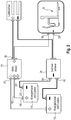
- Fig. 1 shows a schematic view of a drawbar-guided industrial truck 10 which has an electric travel drive and possibly an electrically operated lifting drive.
- the electric drive or drives are fed from a battery module 12; the battery module 12 has a closed housing which is equipped with electrical contacts for the plus and minus poles. Contacts for a data or signal line with which the battery module 12 is connected to a battery management system 14 are not shown.
- the battery management system 14 has its own housing, which is arranged spatially separated from the battery module 12 in the industrial truck 10.
- the positive pole 16 of the battery module 12 is connected to a power connection 20 of the battery management system 14 via a line 18.
- the battery management system 14 also has a data and signal line (not shown) with which status signals and data can be received from the battery module 12.
- a negative pole 22 of the battery module 12 is connected to a negative pole 26 on the industrial truck via a busbar 24.
- this connection is shown symbolically and shows the negative pole 26 and the positive pole 28 of the electrical consumer fed by the battery module 12.
- the connection 28 is connected to an output connection 30 of the battery management system 14.
- the electrical consumer or consumers in the industrial truck 10 are connected with their connection contacts 26 and 28 via the busbar 24 and the battery management system 14 to the battery module 12.
- the industrial truck 10 can be equipped with a charging socket 32.
- the charging socket 32 is equipped as a vehicle-mounted charging socket with a socket 34 accessible from the outside.
- the charging socket 32 is electrically connected via its contacts 36, 38 either to the output contact 30 of the Battery management system or with the busbar 24.
- the charging socket 32 can also be additionally provided with a signal line. This can, for example, be connected directly to a vehicle controller or be applied to the battery management system 14.
- the charging socket ensures, for example via this signal line, that an immobilizer is activated on the vehicle.
- the energy module 12 is fed via contacts 36 and 38 of the charging socket 32, the charging current flowing via the battery management system 14 and the busbar 24.
- Fig. 2 shows a simple expansion of the energy store.
- the same components have the same reference symbols as in FIG Fig. 1 designated.
- the additional battery module 12 is structurally identical to the battery module 12; both battery modules each have eight cells.
- the additional battery module 12 ′ is connected with its positive pole 16 ′ to the battery management system 14 via a line 18 ′ with a power contact 20 ′.
- the battery management system processes the electrical power present from the battery modules 12 and 12 ′ in order to apply it together via the output 30 to the corresponding contact 28.
- the associated negative pole 29 also belongs to the industrial truck 10.
- the contact 22 ′ of the battery module 12 ′ rests on the busbar 24 via the connection 40.
- connections 40, 42 are shown as separate connections, these can also be configured as a common connection on busbar 24.
- the connected negative poles 20, 22 ′ of the battery modules are brought together in the busbar 24 and are jointly applied to its connection 26.
- the exemplary embodiment with two battery modules also shows a further advantage, since the same battery management system 14 is used in both configuration Fig. 1 than when configuring Fig. 2 is used.
- Fig. 3 shows a further alternative embodiment of the electrical energy store. Again, compared to the Figs. 1 and 2 the same reference numerals are used for the same components.
- a battery module 12 ′′ is provided which has two connection contacts 44, 46.
- the connection contacts 44, 46 each conduct approximately half of the current to the power contacts 20, 20 'of the battery management system 14. It is important to note that the two power contacts 20, 20 ', even if they are both connected to a battery module 12', still have the same connections as the exemplary embodiment Fig. 2 are, in which two battery modules 12, 12 'are connected to the battery management system 14.
- Fig. 4 shows a mixed embodiment in which a battery module 12 ′′ and a battery module 12 are connected to the power contacts of the battery management system 14.
- the battery module 12 ′′ is equipped with 16 battery cells and the battery module 12 with eight battery cells.
- the battery module 12 ′′ is connected to the power contacts 20, 20 ′, while the battery module 12 is connected to the connection 20 ′′.
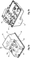
- FIG. 5a shows a battery management system 50 with its housing 52.
- the housing 52 has a bottom 54.
- the connection between the housing 52 and the bottom 54 is sealed by a circumferential seal.
- the Battery management system 50 has three power contacts 58a, 58b and 58c.
- the battery management system 50 is connected to one or more battery modules via the power contacts 58a-c.
- the output from the battery management system takes place via a contact 60.
- a protruding border 62 for a plug connector can be seen on the housing 52.
- the border 62 also forms a wall.
- Figure 5b shows the battery management system in a view from below with the base plate removed.
- the housing 52 is hollow and has a cavity in its dome for receiving the contactor 64.
- the contactors 64 are connected to one another via a busbar 66.
- Each contactor 64 also has a current sensor which detects a critical current strength and opens the contactor.
- the energy store shown in the above exemplary embodiments is designed as a decentralized energy storage system with a battery management system and one or more battery modules.
- switches and current sensors can be arranged in the battery management system and thus simplify the construction of the battery modules.
- the battery modules with different capacities can also be used with the battery management system in unchanged form.
Landscapes
- Engineering & Computer Science (AREA)
- Chemical & Material Sciences (AREA)
- General Chemical & Material Sciences (AREA)
- Electrochemistry (AREA)
- Chemical Kinetics & Catalysis (AREA)
- Sustainable Energy (AREA)
- Mechanical Engineering (AREA)
- Transportation (AREA)
- Power Engineering (AREA)
- Life Sciences & Earth Sciences (AREA)
- Sustainable Development (AREA)
- Manufacturing & Machinery (AREA)
- Electric Propulsion And Braking For Vehicles (AREA)
- Secondary Cells (AREA)
- Charge And Discharge Circuits For Batteries Or The Like (AREA)
Applications Claiming Priority (1)
| Application Number | Priority Date | Filing Date | Title |
|---|---|---|---|
| DE102019124873.6A DE102019124873A1 (de) | 2019-09-16 | 2019-09-16 | Flurförderzeug mit einem elektrischen Energiespeicher |
Publications (1)
| Publication Number | Publication Date |
|---|---|
| EP3792098A1 true EP3792098A1 (fr) | 2021-03-17 |
Family
ID=72470189
Family Applications (1)
| Application Number | Title | Priority Date | Filing Date |
|---|---|---|---|
| EP20195316.3A Pending EP3792098A1 (fr) | 2019-09-16 | 2020-09-09 | Chariot de manutention doté d'un accumulateur d'énergie électrique |
Country Status (4)
| Country | Link |
|---|---|
| US (1) | US20210083259A1 (fr) |
| EP (1) | EP3792098A1 (fr) |
| CN (1) | CN112498175A (fr) |
| DE (1) | DE102019124873A1 (fr) |
Citations (6)
| Publication number | Priority date | Publication date | Assignee | Title |
|---|---|---|---|---|
| DE102009020178A1 (de) | 2009-05-06 | 2010-11-11 | Continental Automotive Gmbh | System zum Speichern von Energie |
| DE102011086495A1 (de) * | 2011-11-16 | 2013-05-16 | Continental Automotive Gmbh | Energiespeichersystem für ein Fahrzeug |
| DE102013113809A1 (de) | 2013-12-11 | 2015-06-11 | Still Gmbh | Flurförderzeug mit batterie-elektrischem Antrieb |
| DE102015108428A1 (de) * | 2015-05-28 | 2016-12-01 | Jungheinrich Aktiengesellschaft | Batterieeinheit für ein Flurförderzeug |
| WO2018031719A1 (fr) * | 2016-08-10 | 2018-02-15 | Briggs & Stratton Corporation | Unité d'alimentation pouvant être mise à l'échelle de l'utilisateur et comprenant des blocs-batteries amovibles |
| EP3534494A1 (fr) * | 2018-02-28 | 2019-09-04 | Delta Electronics (Thailand) Public Co., Ltd. | Transfert de puissance élevée sans fil |
Family Cites Families (15)
| Publication number | Priority date | Publication date | Assignee | Title |
|---|---|---|---|---|
| US20010052433A1 (en) * | 2000-04-14 | 2001-12-20 | Harris Donald B. | Hybrid power supply module |
| US20040100225A1 (en) * | 2002-11-20 | 2004-05-27 | Neil Robert Miles | Cooling and control system for battery charging |
| WO2004063738A2 (fr) * | 2003-01-03 | 2004-07-29 | Johnson Controls Technology Company | Procede et systeme de controle de batterie |
| JP4390609B2 (ja) * | 2004-03-31 | 2009-12-24 | 三洋電機株式会社 | 車両用の電源装置 |
| US8808898B2 (en) * | 2010-01-29 | 2014-08-19 | Renault S.A.S. | Battery pack for an electric powertrain vehicle |
| KR101294176B1 (ko) * | 2011-10-25 | 2013-08-08 | 기아자동차주식회사 | 배터리관리시스템의 전자파 차단을 위한 배터리시스템 |
| KR20130061375A (ko) * | 2011-12-01 | 2013-06-11 | 삼성에스디아이 주식회사 | 배터리 모듈 |
| US9267993B2 (en) * | 2012-05-23 | 2016-02-23 | Lawrence Livermore National Security, Llc | Battery management system with distributed wireless sensors |
| CA2975062A1 (fr) * | 2015-01-30 | 2016-08-04 | Consortium De Recherche Brp - Universite De Sherbrooke S.E.N.C. | Bloc batterie |
| KR101785537B1 (ko) * | 2015-02-26 | 2017-10-16 | 주식회사 엘지화학 | 이차 전지 관리 장치의 기능 검증 시스템 |
| US11258104B2 (en) * | 2015-06-30 | 2022-02-22 | Faraday & Future Inc. | Vehicle energy-storage systems |
| US9692245B2 (en) * | 2015-08-31 | 2017-06-27 | General Electric Company | Battery management system and power connector |
| CN205668503U (zh) * | 2016-06-20 | 2016-11-02 | 福建省汽车工业集团云度新能源汽车股份有限公司 | 一种双电池系统的电动汽车 |
| KR102345506B1 (ko) * | 2017-01-24 | 2021-12-29 | 삼성에스디아이 주식회사 | 배터리 팩, 배터리 팩의 충전 제어 방법, 및 배터리 팩을 포함하는 차량 |
| JP7054442B2 (ja) * | 2018-03-06 | 2022-04-14 | トヨタ自動車株式会社 | 組電池および組電池の製造方法 |
-
2019
- 2019-09-16 DE DE102019124873.6A patent/DE102019124873A1/de active Pending
-
2020
- 2020-09-09 EP EP20195316.3A patent/EP3792098A1/fr active Pending
- 2020-09-14 US US17/019,988 patent/US20210083259A1/en not_active Abandoned
- 2020-09-16 CN CN202010971178.6A patent/CN112498175A/zh active Pending
Patent Citations (6)
| Publication number | Priority date | Publication date | Assignee | Title |
|---|---|---|---|---|
| DE102009020178A1 (de) | 2009-05-06 | 2010-11-11 | Continental Automotive Gmbh | System zum Speichern von Energie |
| DE102011086495A1 (de) * | 2011-11-16 | 2013-05-16 | Continental Automotive Gmbh | Energiespeichersystem für ein Fahrzeug |
| DE102013113809A1 (de) | 2013-12-11 | 2015-06-11 | Still Gmbh | Flurförderzeug mit batterie-elektrischem Antrieb |
| DE102015108428A1 (de) * | 2015-05-28 | 2016-12-01 | Jungheinrich Aktiengesellschaft | Batterieeinheit für ein Flurförderzeug |
| WO2018031719A1 (fr) * | 2016-08-10 | 2018-02-15 | Briggs & Stratton Corporation | Unité d'alimentation pouvant être mise à l'échelle de l'utilisateur et comprenant des blocs-batteries amovibles |
| EP3534494A1 (fr) * | 2018-02-28 | 2019-09-04 | Delta Electronics (Thailand) Public Co., Ltd. | Transfert de puissance élevée sans fil |
Also Published As
| Publication number | Publication date |
|---|---|
| US20210083259A1 (en) | 2021-03-18 |
| DE102019124873A1 (de) | 2021-03-18 |
| CN112498175A (zh) | 2021-03-16 |
Similar Documents
| Publication | Publication Date | Title |
|---|---|---|
| DE19855245B4 (de) | Redundante Spannungsversorgung für elektrische Verbraucher | |
| DE102019105890A1 (de) | Modulares Batteriepacksystem mit Reihen- und Parallelladung und Antriebsmodi | |
| EP2913863B1 (fr) | Unité de stockage d'énergie électrique pour véhicules automobiles | |
| EP1411364B1 (fr) | Tableau de bord d'un véhicule pour identifier l'état de batterie connectée au pôle positif de la batterie | |
| WO2016150792A1 (fr) | Dispositif accumulateur d'énergie | |
| DE102017104958A1 (de) | Batteriespeichersystem und Bordnetz zur fehlertoleranten Versorgung sicherheitsrelevanter Verbraucher in einem Fahrzeug | |
| EP3304673B1 (fr) | Dispositif d'alimentation électrique et réseau de bord de véhicule équipé de ce dispositif | |
| DE102011086495A1 (de) | Energiespeichersystem für ein Fahrzeug | |
| DE102018000490A1 (de) | Speichereinrichtung für ein Kraftfahrzeug, insbesondere für ein Elektrofahrzeug | |
| EP2700611A1 (fr) | Cadre d'adaptateur pour batterie de traction et chariot de manutention avec batterie de traction | |
| EP2794335A2 (fr) | Système de batterie et procédé | |
| DE102012015523B4 (de) | Hochvoltbatterie mit Entlademöglichkeit nach einem Crash | |
| DE19957478A1 (de) | Zwei-Batteriensystem | |
| DE102018100746A1 (de) | Fehlertolerantes Batteriespeichersystem und Bordnetz | |
| DE102018004625A1 (de) | Ladeverfahren und Ladevorrichtung zum Laden eines ersten und eines zweiten elektrisch betriebenen Fahrzeugs | |
| DE10317362B4 (de) | Fahrzeugbordnetz und Verfahren zum Betreiben eines Fahrzeugbordnetzes | |
| EP3571088B1 (fr) | Système de batterie, système de charge et procédé de recharge pour véhicule | |
| EP3006253A1 (fr) | Systeme comprenant au moins deux accumulateurs d'energie de traction electrique | |
| EP3792098A1 (fr) | Chariot de manutention doté d'un accumulateur d'énergie électrique | |
| DE102013222462A1 (de) | Fahrzeugbatterie mit einer Vorrichtung zur Auswahl einer zulässigen Stromrichtung | |
| DE10152701A1 (de) | Elektrischer Akkumulator | |
| DE102016002668A1 (de) | Akkumulator zum reversiblen elektrochemischen Speichern von elektrischer Ladung mittels einer Mehrzahl von galvanischen Zellen | |
| DE102016224005A1 (de) | Elektrische Energiespeichereinrichtung | |
| WO2023175060A1 (fr) | Boîtier de contacteurs modulaire | |
| DE102015225544A1 (de) | Trennvorrichtung in standardisiertem Format |
Legal Events
| Date | Code | Title | Description |
|---|---|---|---|
| PUAI | Public reference made under article 153(3) epc to a published international application that has entered the european phase |
Free format text: ORIGINAL CODE: 0009012 |
|
| STAA | Information on the status of an ep patent application or granted ep patent |
Free format text: STATUS: THE APPLICATION HAS BEEN PUBLISHED |
|
| AK | Designated contracting states |
Kind code of ref document: A1 Designated state(s): AL AT BE BG CH CY CZ DE DK EE ES FI FR GB GR HR HU IE IS IT LI LT LU LV MC MK MT NL NO PL PT RO RS SE SI SK SM TR |
|
| AX | Request for extension of the european patent |
Extension state: BA ME |
|
| STAA | Information on the status of an ep patent application or granted ep patent |
Free format text: STATUS: REQUEST FOR EXAMINATION WAS MADE |
|
| 17P | Request for examination filed |
Effective date: 20210907 |
|
| RBV | Designated contracting states (corrected) |
Designated state(s): AL AT BE BG CH CY CZ DE DK EE ES FI FR GB GR HR HU IE IS IT LI LT LU LV MC MK MT NL NO PL PT RO RS SE SI SK SM TR |
|
| STAA | Information on the status of an ep patent application or granted ep patent |
Free format text: STATUS: EXAMINATION IS IN PROGRESS |
|
| 17Q | First examination report despatched |
Effective date: 20230102 |
|
| P01 | Opt-out of the competence of the unified patent court (upc) registered |
Effective date: 20230628 |