EP3792024A1 - Control system for edge banding machines - Google Patents
Control system for edge banding machines Download PDFInfo
- Publication number
- EP3792024A1 EP3792024A1 EP20195211.6A EP20195211A EP3792024A1 EP 3792024 A1 EP3792024 A1 EP 3792024A1 EP 20195211 A EP20195211 A EP 20195211A EP 3792024 A1 EP3792024 A1 EP 3792024A1
- Authority
- EP
- European Patent Office
- Prior art keywords
- control system
- mirror
- panel
- edge banding
- edge
- Prior art date
- Legal status (The legal status is an assumption and is not a legal conclusion. Google has not performed a legal analysis and makes no representation as to the accuracy of the status listed.)
- Granted
Links
Images




Classifications
-
- B—PERFORMING OPERATIONS; TRANSPORTING
- B27—WORKING OR PRESERVING WOOD OR SIMILAR MATERIAL; NAILING OR STAPLING MACHINES IN GENERAL
- B27D—WORKING VENEER OR PLYWOOD
- B27D5/00—Other working of veneer or plywood specially adapted to veneer or plywood
- B27D5/003—Other working of veneer or plywood specially adapted to veneer or plywood securing a veneer strip to a panel edge
-
- G—PHYSICS
- G01—MEASURING; TESTING
- G01B—MEASURING LENGTH, THICKNESS OR SIMILAR LINEAR DIMENSIONS; MEASURING ANGLES; MEASURING AREAS; MEASURING IRREGULARITIES OF SURFACES OR CONTOURS
- G01B11/00—Measuring arrangements characterised by the use of optical techniques
- G01B11/02—Measuring arrangements characterised by the use of optical techniques for measuring length, width or thickness
- G01B11/022—Measuring arrangements characterised by the use of optical techniques for measuring length, width or thickness by means of tv-camera scanning
-
- B—PERFORMING OPERATIONS; TRANSPORTING
- B27—WORKING OR PRESERVING WOOD OR SIMILAR MATERIAL; NAILING OR STAPLING MACHINES IN GENERAL
- B27N—MANUFACTURE BY DRY PROCESSES OF ARTICLES, WITH OR WITHOUT ORGANIC BINDING AGENTS, MADE FROM PARTICLES OR FIBRES CONSISTING OF WOOD OR OTHER LIGNOCELLULOSIC OR LIKE ORGANIC MATERIAL
- B27N7/00—After-treatment, e.g. reducing swelling or shrinkage, surfacing; Protecting the edges of boards against access of humidity
-
- G—PHYSICS
- G01—MEASURING; TESTING
- G01B—MEASURING LENGTH, THICKNESS OR SIMILAR LINEAR DIMENSIONS; MEASURING ANGLES; MEASURING AREAS; MEASURING IRREGULARITIES OF SURFACES OR CONTOURS
- G01B11/00—Measuring arrangements characterised by the use of optical techniques
- G01B11/02—Measuring arrangements characterised by the use of optical techniques for measuring length, width or thickness
- G01B11/04—Measuring arrangements characterised by the use of optical techniques for measuring length, width or thickness specially adapted for measuring length or width of objects while moving
- G01B11/043—Measuring arrangements characterised by the use of optical techniques for measuring length, width or thickness specially adapted for measuring length or width of objects while moving for measuring length
-
- G—PHYSICS
- G01—MEASURING; TESTING
- G01B—MEASURING LENGTH, THICKNESS OR SIMILAR LINEAR DIMENSIONS; MEASURING ANGLES; MEASURING AREAS; MEASURING IRREGULARITIES OF SURFACES OR CONTOURS
- G01B11/00—Measuring arrangements characterised by the use of optical techniques
- G01B11/02—Measuring arrangements characterised by the use of optical techniques for measuring length, width or thickness
- G01B11/06—Measuring arrangements characterised by the use of optical techniques for measuring length, width or thickness for measuring thickness ; e.g. of sheet material
- G01B11/0691—Measuring arrangements characterised by the use of optical techniques for measuring length, width or thickness for measuring thickness ; e.g. of sheet material of objects while moving
-
- G—PHYSICS
- G01—MEASURING; TESTING
- G01N—INVESTIGATING OR ANALYSING MATERIALS BY DETERMINING THEIR CHEMICAL OR PHYSICAL PROPERTIES
- G01N21/00—Investigating or analysing materials by the use of optical means, i.e. using sub-millimetre waves, infrared, visible or ultraviolet light
- G01N21/84—Systems specially adapted for particular applications
- G01N21/88—Investigating the presence of flaws or contamination
- G01N21/89—Investigating the presence of flaws or contamination in moving material, e.g. running paper or textiles
- G01N21/892—Investigating the presence of flaws or contamination in moving material, e.g. running paper or textiles characterised by the flaw, defect or object feature examined
- G01N21/898—Irregularities in textured or patterned surfaces, e.g. textiles, wood
- G01N21/8986—Wood
Definitions
- the present invention relates to a control system for edge banding machines, which allows the inspection of the vertical edges of a panel made of wood or similar material.
- the present invention lies in the field of machines suitable to control the quality of the panels banding.
- This process includes several steps, including the application of the glue on the side of the panel to be banded, the application of the band on said side, the dimensioning of the band itself according to the height and the length of said side, and any machining, for example radius machining, at the edges of the band and/or the panel.
- the aforesaid processes are carried out while the panel being worked is moving between an inlet station and an outlet station of the edge banding machine, along a predetermined direction.
- the problem that arises at the base of the present invention is to optimize the inspection, downstream of an edging process, of the vertical edges of the head and the tail of a clipboard wooden material panel, since this gluing point of the edge turns out to be one of the most delicate: in that area, in fact, there are the two sides of the panel, with a different angle, in direct contact.
- Known control systems for edge banding machines provide a vision system, consisting of multiple cameras, which do not specifically analyze the vertical edges of the panel, since they are arranged so as not to have a field of vision suitable to the segment to be analyzed. It is evident that this solution does not guarantee the quality control of the vertical edges of the head and tail of the panel.
- a further known control system provides for the use of a single camera, which, being able to rotate, is configured to alternatively inspect, during the passage of the panel, the vertical edges of the head and tail of the panel itself.
- This control system does not guarantee, however, a sufficient precision due to the rotational movement of the camera that should be perfectly synchronized with the high advancement speed of the panel, and because of the possible loss of image definition during said movement.
- the relevant prior art also includes the document EP3462164A1 , which describes a control system, which provides for the use of a single fixed camera which observes alternatively, during the passage of the panel, the head and tail edge of the panel itself. For both edges, said camera acquires a series of images along a direction diagonal with respect to the advancement direction of the panel. These images thus obtained, must then be combined to obtain a single image. This operation is performed because the camera is arranged normal to the advancement direction of the piece, and has a limited field of vision to inspect the head and tail edges of the panel.
- a technical problem of this solution is the possibility of obtaining combined images that differ from reality.
- a further disadvantage of the aforesaid solution is that of having to use a processor with a high computing power, which allows the combination and processing of the images to be performed.
- a control system for edge banding machines having technical features that are present in the preamble of the attached claim 1, is described, for example, in the patent documents EP2687837B1 , EP3462164A1 .
- a control system placed downstream of an edge banding machine which allows the inspection of the vertical edges of a panel made of wood or similar material, with features similar to those that will be described in detail below, is not at present in the market.
- the main purpose of the present invention is to provide a control system for edge banding machines that allows the inspection of the vertical edges of a panel, increasing the performance of the quality control process, thus identifying a greater number of imperfections.
- a further object of the present invention is to provide system control machines for edge banding which allows having control of the processing at the machine output.
- Another object of the present invention is to provide a vision system for quality control, which allows managing the regulation of the contrast between the sides adjacent to the same edge.
- the purpose of the present invention is to expand and improve the field of vision of the control system, in order to have more precise results with a more "lean" processing of the acquired images, given by the reduced quantity of images that need to be acquired and enough fast to be compatible with the machining speed of the machine.
- the object of the invention is to provide a control system for edge banding machines, which can be integrated into edge banding machines even already in use, and which could also integrate in any other control systems for edge banding machines.
- a further object of the invention is to obtain a control system for edge banding machines, which is compact and economical to produce compared to the advantages achieved.
- a control system for an edge banding machine suitable to apply a band to a panel advancing along a sliding direction, in correspondence of a vertical edge, comprising a video camera with a viewing cone provided with a bisector and a first mirror for reflecting an image of the vertical edge of the panel.
- said control system also comprises a second mirror located inside the viewing cone of the video camera and tilted with respect to said bisector at a first angle.
- the first mirror is in a decentralized position with respect to said bisector and tilted in respect to said sliding direction of said panel at a second angle.
- the first and second mirror are adjusted in such a way that said video camera captures the image of said vertical edge of said panel through a first reflection on said first mirror and a second reflection on the second mirror.
- the second mirror can be placed along the bisector.
- the first angle and/or the second angle may be 0-90 degrees.
- the first angle is preferably equal to 80 degrees.
- the second angle is preferably equal to 50 degrees.
- the acquired image is relative to the vertical edge of the head of the panel, instead, if it is located on the right side of the video camera, the acquired image is relative to the vertical edge of the tail of the panel at issue.
- the control system, object of the invention may comprise a first illuminator, externally adjacent to the first mirror with respect to the bisector, in order to illuminate said vertical edge of said panel.
- the first illuminator has the same inclination as said first mirror to illuminate the vertical edge of the panel.
- the system can also be arranged to comprise a second illuminator, arranged symmetrically to the first illuminator with respect to the bisector described above.
- the system can comprise a third and a fourth mirror, which allow having an image relative to a second vertical edge of the panel at issue.
- the third and fourth mirrors can be arranged symmetrically to the second and first mirrors, with respect to the bisector.
- the second and the third mirror may be adjacent in correspondence with a point in axis with the bisector but inclined to each other of a third angle, preferably of 160 degrees.
- the presence of four mirrors, and of their possible angles, given from the second and third angle, allows detecting, advantageously, the images relating to both vertical edges, both head as well as tail of the panel, with a single device.
- the position and angle of the mirrors and/or of the lights can be adjusted through the first adjustment elements.
- the video camera of the control system can also be provided with second adjustment means, adapted to adjust the distance and the angle of the same video camera with respect to the vertical edge of the panel. This can guarantee a more precise acquisition of the detail relating to the vertical edge of the panel.
- control system 15 for edge banding machines 1 object of the present invention comprises a system having a video camera 4 (with its optics) and at least two mirrors 10, for reflecting the desired image, in this case, the head and tail edges of the panel 11, towards the camera 4 belonging to the aforementioned system 15.
- the control system 15 for edge banding machines 1 is preferably positioned ( fig. 1 ) within an empty compartment 3 downstream an edge banding machine 1, along which the panel 11 ( figures 2-6 , 8-9 ) to be banded, made of different materials, for example, chipboard wood, slides according to the longitudinal direction R in figures 1-9 , through a support roller conveyor 2.
- the illustrated panel 11 has ( figure 2 ) two side surfaces 13 parallel and opposite to each other, which correspond to the longer sides of the panel 11 itself; perpendicular to the side surfaces 13 and parallel and opposite to each other, there are two side surfaces 14, which correspond to the shorter sides of a panel.
- the control system 15 for edge banding machines 1 comprises a camera 4, positioned on a camera support 5, which has, laterally and parallel to the sides of the camera 4 itself, pushing grains 16 within slots 17, which allow adjusting the camera 4 with respect to the distance and with respect to the panel 11 to be analyzed, according to a longitudinal direction L in the figure.
- a passage or opening 6 for example of a circular shape, which allows limiting the field of vision of the camera 4 to a certain number of mirrors.
- a hardware support 7 At the rear of the passage or opening 6 and in front of the mirror group 23, there is a hardware support 7.
- a mirrors group 23 which, in this first embodiment comprises two mirrors 10, a first mirror placed in an off-center position with respect to the bisector 20 of the cone of vision of the camera 4, inclined with respect to the advancement direction R of the panel 11 by an angle 19, for example of 50 degrees.
- the second mirror 10 is placed centrally along the trajectory of the bisector 20 of the viewing cone of the camera 4, inclined with respect to the same by an angle 18, for example by 80 degrees.
- angles 18 and 19 of the mirrors 10 enable the camera 4, to detect, in a precise and timed way, one of the two head or tail vertical edges 12. This depends on the decentralized position of the mirror 10, and the angle of inclination of the central mirror 10, with respect to the bisector. If said decentralized mirror is located on the left side sx with respect to the camera 4 and its optics, it will hit the edge of the panel 12 of head 11; if it is located on the right side dx with respect to the camera 4 and to its optics, it will hit and detect the edge 12 of tail 11 of the panel.
- a linear illuminator 8 for example, a LED strip, which points illuminating, in parallel with respect to the decentralized mirror 10, the vertical edge 12 of the panel 11.
- the inclination of the linear illuminator 8 can be different with respect to the inclination of the off-center mirror 10.
- the mirrors 10 and the illuminator 8 can have an adjustable angle and can be positioned by means of pins 21 and recessed fixing grains 22, which screw and pass-through holes ad hoc created in a cover 25 of the mirrors group 23.
- the system has four mirrors 10, two adjacent mirrors 10 in correspondence with a point and inclined to each other of an angle 26 between the two, for example of 160 degrees; these mirrors 10 are preferably placed centrally with respect to the viewing cone of the camera 4, and in particular with the point of contact between the two mirrors 10 themselves at the bisector 20 of this viewing cone, when perpendicular to the advancement direction R of the panel.
- mirrors 10 are inclined, for opposite sides (dx and sx references in the figure), with respect to the bisector 20 of the viewing cone of the camera 4 of an angle 18, for example by 80 degrees, the third mirror 10 in an off-center position with respect to the bisector 20 of the viewing cone of the camera 4, inclined with respect to the advancement direction R of the panel 11, by an angle 19, for example of 50 degrees.
- the fourth mirror 10 is also in an off-centered position with respect to the bisector 20 of the viewing cone of the camera 4, inclined with respect to the advancement direction R of the panel 11, by an angle 19, for example of 50 degrees.
- angles 18 and 19 of the mirrors 10 allow the camera 4 to detect, in a precise and timed way, both the vertical edges 12, both head and tail ones.
- linear illuminators 8 Preferably with the same inclination of the off-centered mirrors 10, and externally close respectively to the same, there are two linear illuminators 8, one for each side: for example, two LED strips, which point and illuminate in parallel with respect to the mirrors 10 on the vertical edge 12 of the panel 11.
- the mirrors 10 and the illuminators 8 can have adjustable angle and position through the pins 21, and recessed fixing grains 22 that screw and pass through the holes created ad hoc in a cover 25 of the mirrors group 23.
- FIG. 5 shows a side view of the control system for edge banding machines, in which a section line A is clearly evident, thanks to which it is possible to view in detail in the figures 6 and 7 , the system described above without the part relating to the cover 25 and to the pins 21, of the mirrors group 23.
- Figures 8 and 9 show two different but consecutive moments of the acquisition step, respectively, of the edge 12 of the head and subsequently of the edge 12 of the tail, according to an advancement direction R in the figure, the panel 11.
- the beam F coming from the illuminator which illuminates the vertical edge 12 of the head of the panel 11, strikes the off-center mirror 10 adjacent to the left, the beam is thus reflected and in turn strikes the central mirror 10, inclined from the left-hand side in the figure and, passing through the passage or opening 6, in a precise way in terms of the beam width F and of timing, it is acquired by the camera.
- the beam F coming from the illuminator, which illuminates the vertical tail edge 12 of the panel 11 strikes the off-center mirror 10 adjacent to the right, the beam is thus reflected and in turn strikes the central mirror 10, inclined from the right side in the figure and, passing through the passage or opening 6, in a precise way in terms of the beam width F and of timing, it is acquired by the camera.
- control system 15 for edge banding machines 1 thus realized, as described above and according to the examples illustrated in detail in the figures 1, 2 , 3, 4 , 5, 6 , 7, 8 , and 9 attached, therefore has the following advantages:
Landscapes
- Life Sciences & Earth Sciences (AREA)
- Engineering & Computer Science (AREA)
- Wood Science & Technology (AREA)
- Physics & Mathematics (AREA)
- General Physics & Mathematics (AREA)
- Textile Engineering (AREA)
- Forests & Forestry (AREA)
- Biochemistry (AREA)
- Analytical Chemistry (AREA)
- General Health & Medical Sciences (AREA)
- Chemical & Material Sciences (AREA)
- Immunology (AREA)
- Pathology (AREA)
- Manufacturing & Machinery (AREA)
- Health & Medical Sciences (AREA)
- Mechanical Engineering (AREA)
- Investigating Materials By The Use Of Optical Means Adapted For Particular Applications (AREA)
- Control Of Velocity Or Acceleration (AREA)
- Paper (AREA)
Abstract
Description
- The present invention relates to a control system for edge banding machines, which allows the inspection of the vertical edges of a panel made of wood or similar material.
- Therefore, the present invention lies in the field of machines suitable to control the quality of the panels banding.
- The realization of a quality control system for parts machined by edge manding machines is currently a noteworthy problem. In fact, due to various and different limitations, for example of a physical and structural type, these quality control systems, in this technological field, are difficult to implement. The edging process of a wooden chipboard panel is designed to cover the sides of a previously sectioned panel with an ennobling edge, applied by gluing. The edge, applied on the side sectional view of the panel, should be as real as possible to the essence of the main surfaces of the panel or otherwise aesthetically matched to it. The edge banding machine is the machine where the edging process takes place. This process includes several steps, including the application of the glue on the side of the panel to be banded, the application of the band on said side, the dimensioning of the band itself according to the height and the length of said side, and any machining, for example radius machining, at the edges of the band and/or the panel. The aforesaid processes are carried out while the panel being worked is moving between an inlet station and an outlet station of the edge banding machine, along a predetermined direction.
- As it is easy to guess, there are several conditions to be respected during this type of machining, aimed at ensuring that the processed panel has optimal characteristics both from a structural point of view (for example with regard to edge sealing), and from an aesthetic point of view. The difficulty of ensuring optimum machining is also due to the fact that the above-mentioned edges can be realized according to various and numerous varieties not only of materials, such as wood, metals, etc. but also that they may comprise several varieties of colors and shapes.
- Since the set of possible defects is very wide, it is easy to understand that the visual inspection by an operator alone is not sufficient to guarantee a high level of quality of the output product.
- The problem that arises at the base of the present invention is to optimize the inspection, downstream of an edging process, of the vertical edges of the head and the tail of a clipboard wooden material panel, since this gluing point of the edge turns out to be one of the most delicate: in that area, in fact, there are the two sides of the panel, with a different angle, in direct contact.
- For this reason, a high level of precision is required, especially in the edge gluing.
- Known control systems for edge banding machines provide a vision system, consisting of multiple cameras, which do not specifically analyze the vertical edges of the panel, since they are arranged so as not to have a field of vision suitable to the segment to be analyzed. It is evident that this solution does not guarantee the quality control of the vertical edges of the head and tail of the panel.
- Other known control systems provide a vision system, which is based on the use of at least two video cameras, pointed so as to alternatively inspect the vertical edges of the head and tail of the panel itself during the passage of the panel. This quality control system, providing for the use of two cameras, is particularly expensive in terms of cost and space on the machine. Furthermore, with this system, it is difficult to manage the adjustment of the contrast between the two sides of the panel relative to the same edge, during the acquisition of the image by the cameras.
- A further known control system provides for the use of a single camera, which, being able to rotate, is configured to alternatively inspect, during the passage of the panel, the vertical edges of the head and tail of the panel itself.
- This control system does not guarantee, however, a sufficient precision due to the rotational movement of the camera that should be perfectly synchronized with the high advancement speed of the panel, and because of the possible loss of image definition during said movement.
- The relevant prior art also includes the document
EP3462164A1 , which describes a control system, which provides for the use of a single fixed camera which observes alternatively, during the passage of the panel, the head and tail edge of the panel itself. For both edges, said camera acquires a series of images along a direction diagonal with respect to the advancement direction of the panel. These images thus obtained, must then be combined to obtain a single image. This operation is performed because the camera is arranged normal to the advancement direction of the piece, and has a limited field of vision to inspect the head and tail edges of the panel. A technical problem of this solution is the possibility of obtaining combined images that differ from reality. A further disadvantage of the aforesaid solution is that of having to use a processor with a high computing power, which allows the combination and processing of the images to be performed. A control system for edge banding machines having technical features that are present in the preamble of the attachedclaim 1, is described, for example, in the patent documentsEP2687837B1 ,EP3462164A1 . - In any case, a control system placed downstream of an edge banding machine, which allows the inspection of the vertical edges of a panel made of wood or similar material, with features similar to those that will be described in detail below, is not at present in the market.
- Within the scope of the requirements mentioned above, therefore, the main purpose of the present invention is to provide a control system for edge banding machines that allows the inspection of the vertical edges of a panel, increasing the performance of the quality control process, thus identifying a greater number of imperfections.
- A further object of the present invention is to provide system control machines for edge banding which allows having control of the processing at the machine output.
- Another object of the present invention is to provide a vision system for quality control, which allows managing the regulation of the contrast between the sides adjacent to the same edge.
- Furthermore, the purpose of the present invention is to expand and improve the field of vision of the control system, in order to have more precise results with a more "lean" processing of the acquired images, given by the reduced quantity of images that need to be acquired and enough fast to be compatible with the machining speed of the machine.
- The object of the invention is to provide a control system for edge banding machines, which can be integrated into edge banding machines even already in use, and which could also integrate in any other control systems for edge banding machines.
- A further object of the invention is to obtain a control system for edge banding machines, which is compact and economical to produce compared to the advantages achieved.
- It is therefore object of the present invention a control system for an edge banding machine, suitable to apply a band to a panel advancing along a sliding direction, in correspondence of a vertical edge, comprising a video camera with a viewing cone provided with a bisector and a first mirror for reflecting an image of the vertical edge of the panel.
- Preferably, according to the invention, said control system also comprises a second mirror located inside the viewing cone of the video camera and tilted with respect to said bisector at a first angle.
- Equally preferably, the first mirror is in a decentralized position with respect to said bisector and tilted in respect to said sliding direction of said panel at a second angle.
- Furthermore, according to the invention, the first and second mirror are adjusted in such a way that said video camera captures the image of said vertical edge of said panel through a first reflection on said first mirror and a second reflection on the second mirror.
- In particular, the second mirror can be placed along the bisector.
- Still, according to the invention, the first angle and/or the second angle may be 0-90 degrees.
- The first angle is preferably equal to 80 degrees.
- The second angle is preferably equal to 50 degrees.
- These angles allow having an optimal result of the reflection of the light beam and of the image acquisition.
- In detail, considering an advancement direction of the panel from left to the right, if the first decentralized mirror is located on the left side of the video camera, the acquired image is relative to the vertical edge of the head of the panel, instead, if it is located on the right side of the video camera, the acquired image is relative to the vertical edge of the tail of the panel at issue.
- The control system, object of the invention, may comprise a first illuminator, externally adjacent to the first mirror with respect to the bisector, in order to illuminate said vertical edge of said panel.
- Preferably, in this case, the first illuminator has the same inclination as said first mirror to illuminate the vertical edge of the panel.
- The system can also be arranged to comprise a second illuminator, arranged symmetrically to the first illuminator with respect to the bisector described above.
- This increases the visibility of any defects along the vertical edges of the panel to be checked.
- Preferably, the system can comprise a third and a fourth mirror, which allow having an image relative to a second vertical edge of the panel at issue.
- Preferably, the third and fourth mirrors can be arranged symmetrically to the second and first mirrors, with respect to the bisector.
- In detail, the second and the third mirror may be adjacent in correspondence with a point in axis with the bisector but inclined to each other of a third angle, preferably of 160 degrees.
- The presence of four mirrors, and of their possible angles, given from the second and third angle, allows detecting, advantageously, the images relating to both vertical edges, both head as well as tail of the panel, with a single device.
- The position and angle of the mirrors and/or of the lights can be adjusted through the first adjustment elements.
- This advantageously allows defining, on the basis of the features of the machine, the optimal visibility of the vertical edges.
- The video camera of the control system can also be provided with second adjustment means, adapted to adjust the distance and the angle of the same video camera with respect to the vertical edge of the panel. This can guarantee a more precise acquisition of the detail relating to the vertical edge of the panel.
- To direct more precisely the visual cone towards the first mirror and the second mirror of the video camera, in the direction of the mirrors, there is a gap or opening in front of the same.
- These and other purposes are achieved by a control system for edge banding machines according to the invention, as will become clearer in the following of the present description of a preferred embodiment, but not exclusive by way of indication and not limitation in the accompanying drawings, in which:
-
figure 1 schematically shows a perspective view of the edge banding machine; -
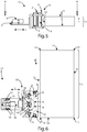
figure 2 shows schematically a top view of a first embodiment of the two mirrors control system for the edge banding machine, according to the invention; -
figure 3 shows schematically a top view of a second embodiment of the four mirrors control system of the edge banding machine, according to the invention; -
figure 4 relates to the control system for edge banding machine offigure 3 , in a perspective view; -
figure 5 relates to a side view of the control system for the edge banding machine offigure 3 ; -
figure 6- i relates to a horizontal section of the control system for the edge banding machine offigure 3 ; -
figure 7 relates to a sectional perspective view of the control system for the edge banding machine offigure 6 ; -
figure 8 schematically shows the control step of the head edge of the panel, for example, made of wooden material, for example in relation to the system offigure 3 ; -
figure 9 schematically shows the control step of the tail edge of the panel, for example, made of wooden material, for example in relation to the system offigure 3 . - With reference to the mentioned figures, the
control system 15 foredge banding machines 1 object of the present invention comprises a system having a video camera 4 (with its optics) and at least twomirrors 10, for reflecting the desired image, in this case, the head and tail edges of thepanel 11, towards thecamera 4 belonging to theaforementioned system 15. - The
control system 15 foredge banding machines 1 is preferably positioned (fig. 1 ) within anempty compartment 3 downstream anedge banding machine 1, along which the panel 11 (figures 2-6 ,8-9 ) to be banded, made of different materials, for example, chipboard wood, slides according to the longitudinal direction R infigures 1-9 , through asupport roller conveyor 2. - The illustrated
panel 11 has (figure 2 ) twoside surfaces 13 parallel and opposite to each other, which correspond to the longer sides of thepanel 11 itself; perpendicular to the side surfaces 13 and parallel and opposite to each other, there are twoside surfaces 14, which correspond to the shorter sides of a panel. - The adjacency points between the side surfaces 13 and side surfaces 14, respectively, form the so-called
vertical edge 12, which is the point of interest of thepanel 11, when analyzed by the control system discussed herein. - In particular, according to a first embodiment of the present invention, visible in
figure 2 , thecontrol system 15 foredge banding machines 1 comprises acamera 4, positioned on acamera support 5, which has, laterally and parallel to the sides of thecamera 4 itself, pushinggrains 16 withinslots 17, which allow adjusting thecamera 4 with respect to the distance and with respect to thepanel 11 to be analyzed, according to a longitudinal direction L in the figure. - In front of the lens of the
camera 4 there is a passage oropening 6, for example of a circular shape, which allows limiting the field of vision of thecamera 4 to a certain number of mirrors. At the rear of the passage oropening 6 and in front of themirror group 23, there is ahardware support 7. - Then, adjacent to the
hardware support 7, in the opposite position with respect to the passage oropening 6, there is amirrors group 23 which, in this first embodiment comprises twomirrors 10, a first mirror placed in an off-center position with respect to thebisector 20 of the cone of vision of thecamera 4, inclined with respect to the advancement direction R of thepanel 11 by anangle 19, for example of 50 degrees. Thesecond mirror 10 is placed centrally along the trajectory of thebisector 20 of the viewing cone of thecamera 4, inclined with respect to the same by anangle 18, for example by 80 degrees. - These
angles mirrors 10 enable thecamera 4, to detect, in a precise and timed way, one of the two head or tail vertical edges 12. This depends on the decentralized position of themirror 10, and the angle of inclination of thecentral mirror 10, with respect to the bisector. If said decentralized mirror is located on the left side sx with respect to thecamera 4 and its optics, it will hit the edge of thepanel 12 ofhead 11; if it is located on the right side dx with respect to thecamera 4 and to its optics, it will hit and detect theedge 12 oftail 11 of the panel. - With the same inclination of the
decentralized mirror 10 and externally close to the same mirror, there is also alinear illuminator 8; for example, a LED strip, which points illuminating, in parallel with respect to thedecentralized mirror 10, thevertical edge 12 of thepanel 11. In a further embodiment, not shown in the figures, the inclination of thelinear illuminator 8 can be different with respect to the inclination of the off-center mirror 10. - In particular, the
mirrors 10 and theilluminator 8 can have an adjustable angle and can be positioned by means ofpins 21 and recessed fixinggrains 22, which screw and pass-through holes ad hoc created in a cover 25 of themirrors group 23. - In an additional embodiment shown in detail in
figures 3 and 4 , the system has fourmirrors 10, twoadjacent mirrors 10 in correspondence with a point and inclined to each other of an angle 26 between the two, for example of 160 degrees; thesemirrors 10 are preferably placed centrally with respect to the viewing cone of thecamera 4, and in particular with the point of contact between the twomirrors 10 themselves at thebisector 20 of this viewing cone, when perpendicular to the advancement direction R of the panel. - These mirrors 10 are inclined, for opposite sides (dx and sx references in the figure), with respect to the
bisector 20 of the viewing cone of thecamera 4 of anangle 18, for example by 80 degrees, thethird mirror 10 in an off-center position with respect to thebisector 20 of the viewing cone of thecamera 4, inclined with respect to the advancement direction R of thepanel 11, by anangle 19, for example of 50 degrees. - In a specular way, the
fourth mirror 10 is also in an off-centered position with respect to thebisector 20 of the viewing cone of thecamera 4, inclined with respect to the advancement direction R of thepanel 11, by anangle 19, for example of 50 degrees. - These
angles mirrors 10 allow thecamera 4 to detect, in a precise and timed way, both thevertical edges 12, both head and tail ones. - Preferably with the same inclination of the off-centered
mirrors 10, and externally close respectively to the same, there are twolinear illuminators 8, one for each side: for example, two LED strips, which point and illuminate in parallel with respect to themirrors 10 on thevertical edge 12 of thepanel 11. - Similarly to the variant shown in
figure 2 , themirrors 10 and theilluminators 8 can have adjustable angle and position through thepins 21, and recessed fixinggrains 22 that screw and pass through the holes created ad hoc in a cover 25 of themirrors group 23. -
Figure 5 shows a side view of the control system for edge banding machines, in which a section line A is clearly evident, thanks to which it is possible to view in detail in thefigures 6 and7 , the system described above without the part relating to the cover 25 and to thepins 21, of themirrors group 23. -
Figures 8 and9 show two different but consecutive moments of the acquisition step, respectively, of theedge 12 of the head and subsequently of theedge 12 of the tail, according to an advancement direction R in the figure, thepanel 11. - In detail, in
figure 8 , the beam F coming from the illuminator, which illuminates thevertical edge 12 of the head of thepanel 11, strikes the off-center mirror 10 adjacent to the left, the beam is thus reflected and in turn strikes thecentral mirror 10, inclined from the left-hand side in the figure and, passing through the passage oropening 6, in a precise way in terms of the beam width F and of timing, it is acquired by the camera. - In
figure 9 , the beam F coming from the illuminator, which illuminates thevertical tail edge 12 of thepanel 11 strikes the off-center mirror 10 adjacent to the right, the beam is thus reflected and in turn strikes thecentral mirror 10, inclined from the right side in the figure and, passing through the passage oropening 6, in a precise way in terms of the beam width F and of timing, it is acquired by the camera. - The
control system 15 foredge banding machines 1 thus realized, as described above and according to the examples illustrated in detail in thefigures 1, 2 ,3, 4 ,5, 6 ,7, 8 , and9 attached, therefore has the following advantages: - Expand and improve the field of vision of the control system;
- Being able to be integrated into existing edge banding machines and other control systems;
- Save the use of an additional camera thanks to the presence of the mirrors and their strategic position;
- Increase the quality of the output machining of the edge banding machine;
- Possibility of consecutively viewing the head and tail edges of a panel;
- Increase the homogeneity of the illumination;
- More accurately evaluate any local contrast defects and therefore edge imperfections;
- Expand and improve the field of vision of the control system in order to have more and more precise results;
- Having a more "lean" processing of the acquired images, given by the reduced quantity of images that have to be acquired;
- Have a fast-enough system to be compatible with the machining speed of the machine;
- Have a system that allows to optimally manage the adjustment of the contrast between the sides adjacent to the same edge;
- Affect a limited production cost, compared to traditional solutions, in relation to the advantages achieved.
- The invention thus conceived and illustrated herein is susceptible of several modifications and variations, all of which are within the scope of the inventive concept.
- Furthermore, all the details can be replaced by other technically equivalent elements.
Claims (15)
- Control system (15) for an edge banding machine (1) suitable to apply a band to a panel (11) advancing along a sliding direction (R) in correspondence with a vertical edge (12), comprising a video camera (4) with a viewing cone provided with a bisector (20) and a first mirror (10) for reflecting an image of the vertical edge (12) of the panel (11),
characterized in that said control system (15) comprises a second mirror (10) located inside the viewing cone of the video camera (4) and tilted with respect to said bisector (20), at a first angle (18);
and in that said first mirror (10) is in a decentralized position with respect to said bisector (20) and tilted in respect with said sliding direction (R) of said panel (11) at a second angle (19), said first and second mirror (10) being adjusted in such a way that said video camera (4) captures the image of said vertical edge (12) of said panel (11) through a first reflection on said first mirror (10) and a second reflection on the second mirror (10). - Control system (15) for an edge banding machine (1) according to claim 1, characterized in that said second mirror (10) is placed along said bisector (20).
- Control system (15) for an edge banding machine (1) according to one of claims 1-2, characterized in that said first angle (18) is equal to 0-90 degrees and/or said second angle (19) is equal to 0-90 degrees.
- Control system (15) for an edge banding machine (1) according to one of claims 1-3, characterized in comprising a first illuminator (8), externally adjacent to said first mirror (10) with respect to the bisector (20), in order to illuminate said vertical edge (12) of said panel (11).
- Control system (15) for an edge banding machine (1) according to claim 4, characterized in that said first illuminator (8) has the same inclination as said first mirror (10).
- Control system (15) for an edge banding machine (1) according to one of claims 1-5, characterized in that said control system (15) comprises a third mirror (10) and a fourth mirror (10) for reflecting an image of a second vertical edge (12) of said panel (11).
- Control system (15) for an edge banding machine (1) as in one of claims 1-6, characterized in that said third and fourth mirrors (10) are arranged symmetrically respectively to the second mirror (10) and to the first mirror (10) with respect to the bisector (20).
- Control system (15) for an edge banding machine (1) as in claim 6 or 7, characterized in that it comprises a second illuminator (8) arranged symmetrically to the first illuminator (8) with the respect to the bisector (20).
- Control system (15) for an edge banding machine (1) according to one of claims 6-7, characterized in that the second and the third mirror (10) are adjacent with each other in correspondence of a point (P) along the bisector (20) and inclined to each other at a third angle (26).
- Control system (15) for an edge banding machine (1) as in claim 9, characterized in that the third angle (26) is equal to 160°.
- Control system (15) for an edge banding machine (1) as in one of claims 1-10, characterized in that the position and the angle of at least one of said mirrors (10) and/or said illuminators (8) is adjustable, through first adjusting elements (21, 22).
- Control system (15) for an edge banding machine as in one of claims 1-11, characterized in that said video camera (4) is equipped with second adjusting means (16) for adjusting the distance and the angle of said video camera (4) with respect to said vertical edge (12) of said panel (11).
- Control system (15) for an edge banding machine (1) as in one of claims 1-12, characterized in that a gap or opening (6) is placed in front of the video camera (4) in order to limit the viewing cone of the video camera (4) towards the first mirror (10) and to the second mirror (10).
- Control system (15) for an edge banding machine (1) as in one of claims 1-13, characterized in that said first angle (18) is equal to 80°.
- Control system (15) for an edge banding machine (1) as in one of claims 1-14, characterized in that the second angle (19) is equal to 50°.
Applications Claiming Priority (1)
| Application Number | Priority Date | Filing Date | Title |
|---|---|---|---|
| IT102019000016187A IT201900016187A1 (en) | 2019-09-12 | 2019-09-12 | CONTROL SYSTEM FOR EDGE BANDING MACHINES |
Publications (2)
| Publication Number | Publication Date |
|---|---|
| EP3792024A1 true EP3792024A1 (en) | 2021-03-17 |
| EP3792024B1 EP3792024B1 (en) | 2022-06-22 |
Family
ID=69375710
Family Applications (1)
| Application Number | Title | Priority Date | Filing Date |
|---|---|---|---|
| EP20195211.6A Active EP3792024B1 (en) | 2019-09-12 | 2020-09-09 | Control system for edge banding machines |
Country Status (3)
| Country | Link |
|---|---|
| EP (1) | EP3792024B1 (en) |
| CN (1) | CN112484643A (en) |
| IT (1) | IT201900016187A1 (en) |
Cited By (2)
| Publication number | Priority date | Publication date | Assignee | Title |
|---|---|---|---|---|
| CN116638468A (en) * | 2023-04-21 | 2023-08-25 | 太仓优上展示器具有限公司 | A cabinet round hole edge banding machine |
| CN119036597A (en) * | 2024-06-05 | 2024-11-29 | 广州玛斯特智能装备有限公司 | Narrow plate circulating edge sealing equipment |
Families Citing this family (1)
| Publication number | Priority date | Publication date | Assignee | Title |
|---|---|---|---|---|
| CN117656200A (en) * | 2022-08-31 | 2024-03-08 | 江苏华工激光科技有限公司 | A laser edge banding combination system |
Citations (4)
| Publication number | Priority date | Publication date | Assignee | Title |
|---|---|---|---|---|
| JPH0292168A (en) * | 1988-09-29 | 1990-03-30 | Maki Seisakusho:Kk | Image pickup device for under side of article |
| US20080239301A1 (en) * | 2007-03-27 | 2008-10-02 | Olympus Corporation | Visual inspection apparatus |
| EP2687837B1 (en) | 2012-07-19 | 2016-10-26 | Baumer Inspection GmbH | Method and system for incident light inspection of at least two opposing top panel edges of a moving panel |
| EP3462164A1 (en) | 2017-09-29 | 2019-04-03 | Baumer Inspection GmbH | Assembly and method of inspecting moved plate-shaped objects |
Family Cites Families (8)
| Publication number | Priority date | Publication date | Assignee | Title |
|---|---|---|---|---|
| DE19716468C2 (en) * | 1997-04-21 | 1999-07-08 | Autronic Bildverarbeitung | Device for surface inspection, especially of wood |
| ITRN20030009A1 (en) * | 2003-04-01 | 2004-10-02 | Scm Group Spa | OPTICAL DEVICE AND COMPUTERIZED SYSTEM FOR THE ACQUISITION OF PROFILES OF PIECES ON A MACHINE TO EDGE WOOD PANELS. |
| CN103808280B (en) * | 2014-01-28 | 2017-01-04 | 华中科技大学 | A kind of based on camera to heart detection method and device |
| CN109190628A (en) * | 2018-08-15 | 2019-01-11 | 东北大学 | A kind of plate camber detection method based on machine vision |
| CN109748071A (en) * | 2019-02-22 | 2019-05-14 | 索菲亚家居湖北有限公司 | The plate edge seal system and its control method of automation |
| CN110065111A (en) * | 2019-05-14 | 2019-07-30 | 索菲亚家居湖北有限公司 | A kind of flexibility edge sealing production system |
| CN110154190A (en) * | 2019-05-15 | 2019-08-23 | 索菲亚家居湖北有限公司 | A kind of household plate production line and detection method with online vision-based detection function |
| CN110207616B (en) * | 2019-06-17 | 2024-02-20 | 德州深华光电科技有限公司 | Shooting device based on reflection light path |
-
2019
- 2019-09-12 IT IT102019000016187A patent/IT201900016187A1/en unknown
-
2020
- 2020-09-09 EP EP20195211.6A patent/EP3792024B1/en active Active
- 2020-09-14 CN CN202010960474.6A patent/CN112484643A/en active Pending
Patent Citations (4)
| Publication number | Priority date | Publication date | Assignee | Title |
|---|---|---|---|---|
| JPH0292168A (en) * | 1988-09-29 | 1990-03-30 | Maki Seisakusho:Kk | Image pickup device for under side of article |
| US20080239301A1 (en) * | 2007-03-27 | 2008-10-02 | Olympus Corporation | Visual inspection apparatus |
| EP2687837B1 (en) | 2012-07-19 | 2016-10-26 | Baumer Inspection GmbH | Method and system for incident light inspection of at least two opposing top panel edges of a moving panel |
| EP3462164A1 (en) | 2017-09-29 | 2019-04-03 | Baumer Inspection GmbH | Assembly and method of inspecting moved plate-shaped objects |
Cited By (2)
| Publication number | Priority date | Publication date | Assignee | Title |
|---|---|---|---|---|
| CN116638468A (en) * | 2023-04-21 | 2023-08-25 | 太仓优上展示器具有限公司 | A cabinet round hole edge banding machine |
| CN119036597A (en) * | 2024-06-05 | 2024-11-29 | 广州玛斯特智能装备有限公司 | Narrow plate circulating edge sealing equipment |
Also Published As
| Publication number | Publication date |
|---|---|
| EP3792024B1 (en) | 2022-06-22 |
| CN112484643A (en) | 2021-03-12 |
| IT201900016187A1 (en) | 2021-03-12 |
Similar Documents
| Publication | Publication Date | Title |
|---|---|---|
| EP3792024B1 (en) | Control system for edge banding machines | |
| AU2016242468B2 (en) | A novel color based optical grading system with multi reflectance and multi-angle views | |
| US7623249B2 (en) | Automated product profiling apparatus and product slicing system using same | |
| AU2002312813B2 (en) | Slicing method and device | |
| US10094785B2 (en) | Method and system for optically inspecting headed manufactured parts | |
| US9030671B2 (en) | Measuring assembly for measuring a spectacle frame | |
| CN104550048B (en) | Diameter measurement device for rod-like products as well as discharging and sorting mechanism and sorting roll of device | |
| US6496219B1 (en) | Automatic system for detecting printing faults on metallized strips or any other printing support comprising a predominance of specular color surfaces | |
| JPH0880475A (en) | Automatic sorting device for sorting small-size product according to form and color in pharmaceutical industry, confectionery industry,etc. | |
| CN110166702B (en) | Camera and method for capturing image data | |
| US7185574B2 (en) | Method and device for separating disc-shaped bodies from an original body | |
| EP3815864A1 (en) | An edging quality control process and an edge banding machine | |
| US20090066944A1 (en) | Device and method for detecting a defect in a finnish ring of a glass | |
| CN213933621U (en) | Candy packaging defect detection platform based on machine vision | |
| US10571405B2 (en) | Quality control station for a sheet element processing machine and illumination unit for the quality control station | |
| JP5099837B2 (en) | Material slicing method and slicing apparatus | |
| CN218788002U (en) | Surface defect detection system and surface detection production line | |
| CN204448613U (en) | A kind of diameter measuring device of rod-shaped products and blanking mechanism for sorting thereof and sorting roller | |
| US20130327828A1 (en) | Image capture system | |
| US7305118B2 (en) | Illumination system for measurement system | |
| US20210086250A1 (en) | Method for operating a processing installation with a movable punch | |
| US5818594A (en) | Method and apparatus for measuring the dimensions of three-dimensional objects such as chips used in pulp manufacture | |
| TWI529387B (en) | Optical detection device | |
| CN110201910B (en) | Color sorter | |
| EP2647290B1 (en) | Assembly and method for orienting a dough piece |
Legal Events
| Date | Code | Title | Description |
|---|---|---|---|
| PUAI | Public reference made under article 153(3) epc to a published international application that has entered the european phase |
Free format text: ORIGINAL CODE: 0009012 |
|
| STAA | Information on the status of an ep patent application or granted ep patent |
Free format text: STATUS: THE APPLICATION HAS BEEN PUBLISHED |
|
| AK | Designated contracting states |
Kind code of ref document: A1 Designated state(s): AL AT BE BG CH CY CZ DE DK EE ES FI FR GB GR HR HU IE IS IT LI LT LU LV MC MK MT NL NO PL PT RO RS SE SI SK SM TR |
|
| AX | Request for extension of the european patent |
Extension state: BA ME |
|
| STAA | Information on the status of an ep patent application or granted ep patent |
Free format text: STATUS: REQUEST FOR EXAMINATION WAS MADE |
|
| 17P | Request for examination filed |
Effective date: 20210913 |
|
| RBV | Designated contracting states (corrected) |
Designated state(s): AL AT BE BG CH CY CZ DE DK EE ES FI FR GB GR HR HU IE IS IT LI LT LU LV MC MK MT NL NO PL PT RO RS SE SI SK SM TR |
|
| GRAP | Despatch of communication of intention to grant a patent |
Free format text: ORIGINAL CODE: EPIDOSNIGR1 |
|
| STAA | Information on the status of an ep patent application or granted ep patent |
Free format text: STATUS: GRANT OF PATENT IS INTENDED |
|
| INTG | Intention to grant announced |
Effective date: 20220120 |
|
| GRAS | Grant fee paid |
Free format text: ORIGINAL CODE: EPIDOSNIGR3 |
|
| GRAA | (expected) grant |
Free format text: ORIGINAL CODE: 0009210 |
|
| STAA | Information on the status of an ep patent application or granted ep patent |
Free format text: STATUS: THE PATENT HAS BEEN GRANTED |
|
| AK | Designated contracting states |
Kind code of ref document: B1 Designated state(s): AL AT BE BG CH CY CZ DE DK EE ES FI FR GB GR HR HU IE IS IT LI LT LU LV MC MK MT NL NO PL PT RO RS SE SI SK SM TR |
|
| REG | Reference to a national code |
Ref country code: GB Ref legal event code: FG4D |
|
| REG | Reference to a national code |
Ref country code: CH Ref legal event code: EP |
|
| REG | Reference to a national code |
Ref country code: DE Ref legal event code: R096 Ref document number: 602020003653 Country of ref document: DE |
|
| REG | Reference to a national code |
Ref country code: AT Ref legal event code: REF Ref document number: 1499491 Country of ref document: AT Kind code of ref document: T Effective date: 20220715 |
|
| REG | Reference to a national code |
Ref country code: IE Ref legal event code: FG4D |
|
| REG | Reference to a national code |
Ref country code: LT Ref legal event code: MG9D |
|
| REG | Reference to a national code |
Ref country code: NL Ref legal event code: MP Effective date: 20220622 |
|
| PG25 | Lapsed in a contracting state [announced via postgrant information from national office to epo] |
Ref country code: SE Free format text: LAPSE BECAUSE OF FAILURE TO SUBMIT A TRANSLATION OF THE DESCRIPTION OR TO PAY THE FEE WITHIN THE PRESCRIBED TIME-LIMIT Effective date: 20220622 Ref country code: NO Free format text: LAPSE BECAUSE OF FAILURE TO SUBMIT A TRANSLATION OF THE DESCRIPTION OR TO PAY THE FEE WITHIN THE PRESCRIBED TIME-LIMIT Effective date: 20220922 Ref country code: LT Free format text: LAPSE BECAUSE OF FAILURE TO SUBMIT A TRANSLATION OF THE DESCRIPTION OR TO PAY THE FEE WITHIN THE PRESCRIBED TIME-LIMIT Effective date: 20220622 Ref country code: HR Free format text: LAPSE BECAUSE OF FAILURE TO SUBMIT A TRANSLATION OF THE DESCRIPTION OR TO PAY THE FEE WITHIN THE PRESCRIBED TIME-LIMIT Effective date: 20220622 Ref country code: GR Free format text: LAPSE BECAUSE OF FAILURE TO SUBMIT A TRANSLATION OF THE DESCRIPTION OR TO PAY THE FEE WITHIN THE PRESCRIBED TIME-LIMIT Effective date: 20220923 Ref country code: FI Free format text: LAPSE BECAUSE OF FAILURE TO SUBMIT A TRANSLATION OF THE DESCRIPTION OR TO PAY THE FEE WITHIN THE PRESCRIBED TIME-LIMIT Effective date: 20220622 Ref country code: BG Free format text: LAPSE BECAUSE OF FAILURE TO SUBMIT A TRANSLATION OF THE DESCRIPTION OR TO PAY THE FEE WITHIN THE PRESCRIBED TIME-LIMIT Effective date: 20220922 |
|
| PG25 | Lapsed in a contracting state [announced via postgrant information from national office to epo] |
Ref country code: RS Free format text: LAPSE BECAUSE OF FAILURE TO SUBMIT A TRANSLATION OF THE DESCRIPTION OR TO PAY THE FEE WITHIN THE PRESCRIBED TIME-LIMIT Effective date: 20220622 Ref country code: LV Free format text: LAPSE BECAUSE OF FAILURE TO SUBMIT A TRANSLATION OF THE DESCRIPTION OR TO PAY THE FEE WITHIN THE PRESCRIBED TIME-LIMIT Effective date: 20220622 |
|
| PG25 | Lapsed in a contracting state [announced via postgrant information from national office to epo] |
Ref country code: NL Free format text: LAPSE BECAUSE OF FAILURE TO SUBMIT A TRANSLATION OF THE DESCRIPTION OR TO PAY THE FEE WITHIN THE PRESCRIBED TIME-LIMIT Effective date: 20220622 |
|
| PG25 | Lapsed in a contracting state [announced via postgrant information from national office to epo] |
Ref country code: SM Free format text: LAPSE BECAUSE OF FAILURE TO SUBMIT A TRANSLATION OF THE DESCRIPTION OR TO PAY THE FEE WITHIN THE PRESCRIBED TIME-LIMIT Effective date: 20220622 Ref country code: SK Free format text: LAPSE BECAUSE OF FAILURE TO SUBMIT A TRANSLATION OF THE DESCRIPTION OR TO PAY THE FEE WITHIN THE PRESCRIBED TIME-LIMIT Effective date: 20220622 Ref country code: RO Free format text: LAPSE BECAUSE OF FAILURE TO SUBMIT A TRANSLATION OF THE DESCRIPTION OR TO PAY THE FEE WITHIN THE PRESCRIBED TIME-LIMIT Effective date: 20220622 Ref country code: PT Free format text: LAPSE BECAUSE OF FAILURE TO SUBMIT A TRANSLATION OF THE DESCRIPTION OR TO PAY THE FEE WITHIN THE PRESCRIBED TIME-LIMIT Effective date: 20221024 Ref country code: ES Free format text: LAPSE BECAUSE OF FAILURE TO SUBMIT A TRANSLATION OF THE DESCRIPTION OR TO PAY THE FEE WITHIN THE PRESCRIBED TIME-LIMIT Effective date: 20220622 Ref country code: EE Free format text: LAPSE BECAUSE OF FAILURE TO SUBMIT A TRANSLATION OF THE DESCRIPTION OR TO PAY THE FEE WITHIN THE PRESCRIBED TIME-LIMIT Effective date: 20220622 Ref country code: CZ Free format text: LAPSE BECAUSE OF FAILURE TO SUBMIT A TRANSLATION OF THE DESCRIPTION OR TO PAY THE FEE WITHIN THE PRESCRIBED TIME-LIMIT Effective date: 20220622 |
|
| PG25 | Lapsed in a contracting state [announced via postgrant information from national office to epo] |
Ref country code: PL Free format text: LAPSE BECAUSE OF FAILURE TO SUBMIT A TRANSLATION OF THE DESCRIPTION OR TO PAY THE FEE WITHIN THE PRESCRIBED TIME-LIMIT Effective date: 20220622 Ref country code: IS Free format text: LAPSE BECAUSE OF FAILURE TO SUBMIT A TRANSLATION OF THE DESCRIPTION OR TO PAY THE FEE WITHIN THE PRESCRIBED TIME-LIMIT Effective date: 20221022 |
|
| REG | Reference to a national code |
Ref country code: DE Ref legal event code: R097 Ref document number: 602020003653 Country of ref document: DE |
|
| PG25 | Lapsed in a contracting state [announced via postgrant information from national office to epo] |
Ref country code: AL Free format text: LAPSE BECAUSE OF FAILURE TO SUBMIT A TRANSLATION OF THE DESCRIPTION OR TO PAY THE FEE WITHIN THE PRESCRIBED TIME-LIMIT Effective date: 20220622 |
|
| PG25 | Lapsed in a contracting state [announced via postgrant information from national office to epo] |
Ref country code: MC Free format text: LAPSE BECAUSE OF FAILURE TO SUBMIT A TRANSLATION OF THE DESCRIPTION OR TO PAY THE FEE WITHIN THE PRESCRIBED TIME-LIMIT Effective date: 20220622 Ref country code: DK Free format text: LAPSE BECAUSE OF FAILURE TO SUBMIT A TRANSLATION OF THE DESCRIPTION OR TO PAY THE FEE WITHIN THE PRESCRIBED TIME-LIMIT Effective date: 20220622 |
|
| PLBE | No opposition filed within time limit |
Free format text: ORIGINAL CODE: 0009261 |
|
| STAA | Information on the status of an ep patent application or granted ep patent |
Free format text: STATUS: NO OPPOSITION FILED WITHIN TIME LIMIT |
|
| REG | Reference to a national code |
Ref country code: BE Ref legal event code: MM Effective date: 20220930 |
|
| 26N | No opposition filed |
Effective date: 20230323 |
|
| P01 | Opt-out of the competence of the unified patent court (upc) registered |
Effective date: 20230519 |
|
| PG25 | Lapsed in a contracting state [announced via postgrant information from national office to epo] |
Ref country code: LU Free format text: LAPSE BECAUSE OF NON-PAYMENT OF DUE FEES Effective date: 20220909 |
|
| PG25 | Lapsed in a contracting state [announced via postgrant information from national office to epo] |
Ref country code: IE Free format text: LAPSE BECAUSE OF NON-PAYMENT OF DUE FEES Effective date: 20220909 Ref country code: FR Free format text: LAPSE BECAUSE OF NON-PAYMENT OF DUE FEES Effective date: 20220930 |
|
| PG25 | Lapsed in a contracting state [announced via postgrant information from national office to epo] |
Ref country code: SI Free format text: LAPSE BECAUSE OF FAILURE TO SUBMIT A TRANSLATION OF THE DESCRIPTION OR TO PAY THE FEE WITHIN THE PRESCRIBED TIME-LIMIT Effective date: 20220622 |
|
| PG25 | Lapsed in a contracting state [announced via postgrant information from national office to epo] |
Ref country code: BE Free format text: LAPSE BECAUSE OF NON-PAYMENT OF DUE FEES Effective date: 20220930 |
|
| REG | Reference to a national code |
Ref country code: AT Ref legal event code: UEP Ref document number: 1499491 Country of ref document: AT Kind code of ref document: T Effective date: 20220622 |
|
| PG25 | Lapsed in a contracting state [announced via postgrant information from national office to epo] |
Ref country code: CY Free format text: LAPSE BECAUSE OF FAILURE TO SUBMIT A TRANSLATION OF THE DESCRIPTION OR TO PAY THE FEE WITHIN THE PRESCRIBED TIME-LIMIT Effective date: 20220622 |
|
| REG | Reference to a national code |
Ref country code: CH Ref legal event code: PL |
|
| PG25 | Lapsed in a contracting state [announced via postgrant information from national office to epo] |
Ref country code: MK Free format text: LAPSE BECAUSE OF FAILURE TO SUBMIT A TRANSLATION OF THE DESCRIPTION OR TO PAY THE FEE WITHIN THE PRESCRIBED TIME-LIMIT Effective date: 20220622 Ref country code: HU Free format text: LAPSE BECAUSE OF FAILURE TO SUBMIT A TRANSLATION OF THE DESCRIPTION OR TO PAY THE FEE WITHIN THE PRESCRIBED TIME-LIMIT; INVALID AB INITIO Effective date: 20200909 |
|
| PG25 | Lapsed in a contracting state [announced via postgrant information from national office to epo] |
Ref country code: TR Free format text: LAPSE BECAUSE OF FAILURE TO SUBMIT A TRANSLATION OF THE DESCRIPTION OR TO PAY THE FEE WITHIN THE PRESCRIBED TIME-LIMIT Effective date: 20220622 |
|
| PG25 | Lapsed in a contracting state [announced via postgrant information from national office to epo] |
Ref country code: CH Free format text: LAPSE BECAUSE OF NON-PAYMENT OF DUE FEES Effective date: 20230930 |
|
| PG25 | Lapsed in a contracting state [announced via postgrant information from national office to epo] |
Ref country code: CH Free format text: LAPSE BECAUSE OF NON-PAYMENT OF DUE FEES Effective date: 20230930 |
|
| PG25 | Lapsed in a contracting state [announced via postgrant information from national office to epo] |
Ref country code: MT Free format text: LAPSE BECAUSE OF FAILURE TO SUBMIT A TRANSLATION OF THE DESCRIPTION OR TO PAY THE FEE WITHIN THE PRESCRIBED TIME-LIMIT Effective date: 20220622 |
|
| PG25 | Lapsed in a contracting state [announced via postgrant information from national office to epo] |
Ref country code: BG Free format text: LAPSE BECAUSE OF FAILURE TO SUBMIT A TRANSLATION OF THE DESCRIPTION OR TO PAY THE FEE WITHIN THE PRESCRIBED TIME-LIMIT Effective date: 20220622 |
|
| PG25 | Lapsed in a contracting state [announced via postgrant information from national office to epo] |
Ref country code: BG Free format text: LAPSE BECAUSE OF FAILURE TO SUBMIT A TRANSLATION OF THE DESCRIPTION OR TO PAY THE FEE WITHIN THE PRESCRIBED TIME-LIMIT Effective date: 20220622 |
|
| GBPC | Gb: european patent ceased through non-payment of renewal fee |
Effective date: 20240909 |
|
| PG25 | Lapsed in a contracting state [announced via postgrant information from national office to epo] |
Ref country code: GB Free format text: LAPSE BECAUSE OF NON-PAYMENT OF DUE FEES Effective date: 20240909 |
|
| PGFP | Annual fee paid to national office [announced via postgrant information from national office to epo] |
Ref country code: DE Payment date: 20250919 Year of fee payment: 6 |
|
| PGFP | Annual fee paid to national office [announced via postgrant information from national office to epo] |
Ref country code: IT Payment date: 20250610 Year of fee payment: 6 |
|
| PGFP | Annual fee paid to national office [announced via postgrant information from national office to epo] |
Ref country code: AT Payment date: 20250918 Year of fee payment: 6 |