EP3791913B1 - Conduit connector for a patient breathing device - Google Patents
Conduit connector for a patient breathing device Download PDFInfo
- Publication number
- EP3791913B1 EP3791913B1 EP20201090.6A EP20201090A EP3791913B1 EP 3791913 B1 EP3791913 B1 EP 3791913B1 EP 20201090 A EP20201090 A EP 20201090A EP 3791913 B1 EP3791913 B1 EP 3791913B1
- Authority
- EP
- European Patent Office
- Prior art keywords
- connector
- conduit
- conduit connector
- locking
- adapter
- Prior art date
- Legal status (The legal status is an assumption and is not a legal conclusion. Google has not performed a legal analysis and makes no representation as to the accuracy of the status listed.)
- Active
Links
- 230000029058 respiratory gaseous exchange Effects 0.000 title description 7
- 239000007789 gas Substances 0.000 claims description 61
- 238000003780 insertion Methods 0.000 claims description 18
- 230000037431 insertion Effects 0.000 claims description 18
- 230000007246 mechanism Effects 0.000 claims description 16
- 241001441752 Philesturnus carunculatus Species 0.000 claims description 2
- 230000003993 interaction Effects 0.000 claims 1
- 239000000523 sample Substances 0.000 description 57
- QVGXLLKOCUKJST-UHFFFAOYSA-N atomic oxygen Chemical compound [O] QVGXLLKOCUKJST-UHFFFAOYSA-N 0.000 description 11
- 229910052760 oxygen Inorganic materials 0.000 description 11
- 239000001301 oxygen Substances 0.000 description 11
- 238000005259 measurement Methods 0.000 description 7
- 239000000463 material Substances 0.000 description 6
- 238000012544 monitoring process Methods 0.000 description 4
- CURLTUGMZLYLDI-UHFFFAOYSA-N Carbon dioxide Chemical compound O=C=O CURLTUGMZLYLDI-UHFFFAOYSA-N 0.000 description 3
- 230000008901 benefit Effects 0.000 description 3
- 239000004020 conductor Substances 0.000 description 3
- -1 polypropylene Polymers 0.000 description 3
- MWUXSHHQAYIFBG-UHFFFAOYSA-N Nitric oxide Chemical compound O=[N] MWUXSHHQAYIFBG-UHFFFAOYSA-N 0.000 description 2
- 239000004743 Polypropylene Substances 0.000 description 2
- 239000000853 adhesive Substances 0.000 description 2
- 230000001070 adhesive effect Effects 0.000 description 2
- 230000009286 beneficial effect Effects 0.000 description 2
- 229910002092 carbon dioxide Inorganic materials 0.000 description 2
- 239000001569 carbon dioxide Substances 0.000 description 2
- 230000008859 change Effects 0.000 description 2
- 230000009977 dual effect Effects 0.000 description 2
- 239000000203 mixture Substances 0.000 description 2
- 238000002640 oxygen therapy Methods 0.000 description 2
- 239000004033 plastic Substances 0.000 description 2
- 229920003023 plastic Polymers 0.000 description 2
- 229920001155 polypropylene Polymers 0.000 description 2
- 241001631457 Cannula Species 0.000 description 1
- 239000004677 Nylon Substances 0.000 description 1
- 239000004698 Polyethylene Substances 0.000 description 1
- 229910000639 Spring steel Inorganic materials 0.000 description 1
- 229920000122 acrylonitrile butadiene styrene Polymers 0.000 description 1
- 239000013043 chemical agent Substances 0.000 description 1
- 230000005494 condensation Effects 0.000 description 1
- 238000009833 condensation Methods 0.000 description 1
- 238000010276 construction Methods 0.000 description 1
- 230000001419 dependent effect Effects 0.000 description 1
- 238000013461 design Methods 0.000 description 1
- 229910003460 diamond Inorganic materials 0.000 description 1
- 239000010432 diamond Substances 0.000 description 1
- 229920001971 elastomer Polymers 0.000 description 1
- 230000006870 function Effects 0.000 description 1
- 239000011521 glass Substances 0.000 description 1
- 230000036541 health Effects 0.000 description 1
- 238000010438 heat treatment Methods 0.000 description 1
- 230000002401 inhibitory effect Effects 0.000 description 1
- 239000002184 metal Substances 0.000 description 1
- 238000012986 modification Methods 0.000 description 1
- 230000004048 modification Effects 0.000 description 1
- 229920001778 nylon Polymers 0.000 description 1
- 229920000515 polycarbonate Polymers 0.000 description 1
- 239000004417 polycarbonate Substances 0.000 description 1
- 229920000573 polyethylene Polymers 0.000 description 1
- 229920001296 polysiloxane Polymers 0.000 description 1
- 229920002635 polyurethane Polymers 0.000 description 1
- 239000004814 polyurethane Substances 0.000 description 1
- 229920000915 polyvinyl chloride Polymers 0.000 description 1
- 239000004800 polyvinyl chloride Substances 0.000 description 1
- 239000005060 rubber Substances 0.000 description 1
- 238000005070 sampling Methods 0.000 description 1
- 238000009964 serging Methods 0.000 description 1
- 238000004513 sizing Methods 0.000 description 1
- 239000000126 substance Substances 0.000 description 1
- 230000000153 supplemental effect Effects 0.000 description 1
- 238000002560 therapeutic procedure Methods 0.000 description 1
- 229920001169 thermoplastic Polymers 0.000 description 1
- 229920002725 thermoplastic elastomer Polymers 0.000 description 1
- 239000004416 thermosoftening plastic Substances 0.000 description 1
- 238000002627 tracheal intubation Methods 0.000 description 1
- 238000013022 venting Methods 0.000 description 1
Images


Classifications
-
- A—HUMAN NECESSITIES
- A61—MEDICAL OR VETERINARY SCIENCE; HYGIENE
- A61M—DEVICES FOR INTRODUCING MEDIA INTO, OR ONTO, THE BODY; DEVICES FOR TRANSDUCING BODY MEDIA OR FOR TAKING MEDIA FROM THE BODY; DEVICES FOR PRODUCING OR ENDING SLEEP OR STUPOR
- A61M39/00—Tubes, tube connectors, tube couplings, valves, access sites or the like, specially adapted for medical use
- A61M39/10—Tube connectors; Tube couplings
- A61M39/1011—Locking means for securing connection; Additional tamper safeties
-
- A—HUMAN NECESSITIES
- A61—MEDICAL OR VETERINARY SCIENCE; HYGIENE
- A61M—DEVICES FOR INTRODUCING MEDIA INTO, OR ONTO, THE BODY; DEVICES FOR TRANSDUCING BODY MEDIA OR FOR TAKING MEDIA FROM THE BODY; DEVICES FOR PRODUCING OR ENDING SLEEP OR STUPOR
- A61M16/00—Devices for influencing the respiratory system of patients by gas treatment, e.g. mouth-to-mouth respiration; Tracheal tubes
- A61M16/06—Respiratory or anaesthetic masks
- A61M16/0666—Nasal cannulas or tubing
- A61M16/0672—Nasal cannula assemblies for oxygen therapy
-
- A—HUMAN NECESSITIES
- A61—MEDICAL OR VETERINARY SCIENCE; HYGIENE
- A61M—DEVICES FOR INTRODUCING MEDIA INTO, OR ONTO, THE BODY; DEVICES FOR TRANSDUCING BODY MEDIA OR FOR TAKING MEDIA FROM THE BODY; DEVICES FOR PRODUCING OR ENDING SLEEP OR STUPOR
- A61M16/00—Devices for influencing the respiratory system of patients by gas treatment, e.g. mouth-to-mouth respiration; Tracheal tubes
- A61M16/08—Bellows; Connecting tubes ; Water traps; Patient circuits
- A61M16/0816—Joints or connectors
-
- A—HUMAN NECESSITIES
- A61—MEDICAL OR VETERINARY SCIENCE; HYGIENE
- A61B—DIAGNOSIS; SURGERY; IDENTIFICATION
- A61B5/00—Measuring for diagnostic purposes; Identification of persons
- A61B5/08—Detecting, measuring or recording devices for evaluating the respiratory organs
- A61B5/082—Evaluation by breath analysis, e.g. determination of the chemical composition of exhaled breath
-
- A—HUMAN NECESSITIES
- A61—MEDICAL OR VETERINARY SCIENCE; HYGIENE
- A61M—DEVICES FOR INTRODUCING MEDIA INTO, OR ONTO, THE BODY; DEVICES FOR TRANSDUCING BODY MEDIA OR FOR TAKING MEDIA FROM THE BODY; DEVICES FOR PRODUCING OR ENDING SLEEP OR STUPOR
- A61M16/00—Devices for influencing the respiratory system of patients by gas treatment, e.g. mouth-to-mouth respiration; Tracheal tubes
- A61M16/0003—Accessories therefor, e.g. sensors, vibrators, negative pressure
-
- A—HUMAN NECESSITIES
- A61—MEDICAL OR VETERINARY SCIENCE; HYGIENE
- A61M—DEVICES FOR INTRODUCING MEDIA INTO, OR ONTO, THE BODY; DEVICES FOR TRANSDUCING BODY MEDIA OR FOR TAKING MEDIA FROM THE BODY; DEVICES FOR PRODUCING OR ENDING SLEEP OR STUPOR
- A61M16/00—Devices for influencing the respiratory system of patients by gas treatment, e.g. mouth-to-mouth respiration; Tracheal tubes
- A61M16/021—Devices for influencing the respiratory system of patients by gas treatment, e.g. mouth-to-mouth respiration; Tracheal tubes operated by electrical means
-
- A—HUMAN NECESSITIES
- A61—MEDICAL OR VETERINARY SCIENCE; HYGIENE
- A61M—DEVICES FOR INTRODUCING MEDIA INTO, OR ONTO, THE BODY; DEVICES FOR TRANSDUCING BODY MEDIA OR FOR TAKING MEDIA FROM THE BODY; DEVICES FOR PRODUCING OR ENDING SLEEP OR STUPOR
- A61M16/00—Devices for influencing the respiratory system of patients by gas treatment, e.g. mouth-to-mouth respiration; Tracheal tubes
- A61M16/06—Respiratory or anaesthetic masks
- A61M16/0666—Nasal cannulas or tubing
-
- A—HUMAN NECESSITIES
- A61—MEDICAL OR VETERINARY SCIENCE; HYGIENE
- A61M—DEVICES FOR INTRODUCING MEDIA INTO, OR ONTO, THE BODY; DEVICES FOR TRANSDUCING BODY MEDIA OR FOR TAKING MEDIA FROM THE BODY; DEVICES FOR PRODUCING OR ENDING SLEEP OR STUPOR
- A61M16/00—Devices for influencing the respiratory system of patients by gas treatment, e.g. mouth-to-mouth respiration; Tracheal tubes
- A61M16/08—Bellows; Connecting tubes ; Water traps; Patient circuits
- A61M16/0816—Joints or connectors
- A61M16/0825—Joints or connectors with ball-sockets
-
- A—HUMAN NECESSITIES
- A61—MEDICAL OR VETERINARY SCIENCE; HYGIENE
- A61M—DEVICES FOR INTRODUCING MEDIA INTO, OR ONTO, THE BODY; DEVICES FOR TRANSDUCING BODY MEDIA OR FOR TAKING MEDIA FROM THE BODY; DEVICES FOR PRODUCING OR ENDING SLEEP OR STUPOR
- A61M16/00—Devices for influencing the respiratory system of patients by gas treatment, e.g. mouth-to-mouth respiration; Tracheal tubes
- A61M16/08—Bellows; Connecting tubes ; Water traps; Patient circuits
- A61M16/0816—Joints or connectors
- A61M16/0833—T- or Y-type connectors, e.g. Y-piece
-
- A—HUMAN NECESSITIES
- A61—MEDICAL OR VETERINARY SCIENCE; HYGIENE
- A61M—DEVICES FOR INTRODUCING MEDIA INTO, OR ONTO, THE BODY; DEVICES FOR TRANSDUCING BODY MEDIA OR FOR TAKING MEDIA FROM THE BODY; DEVICES FOR PRODUCING OR ENDING SLEEP OR STUPOR
- A61M16/00—Devices for influencing the respiratory system of patients by gas treatment, e.g. mouth-to-mouth respiration; Tracheal tubes
- A61M16/08—Bellows; Connecting tubes ; Water traps; Patient circuits
- A61M16/0816—Joints or connectors
- A61M16/0841—Joints or connectors for sampling
- A61M16/085—Gas sampling
-
- A—HUMAN NECESSITIES
- A61—MEDICAL OR VETERINARY SCIENCE; HYGIENE
- A61M—DEVICES FOR INTRODUCING MEDIA INTO, OR ONTO, THE BODY; DEVICES FOR TRANSDUCING BODY MEDIA OR FOR TAKING MEDIA FROM THE BODY; DEVICES FOR PRODUCING OR ENDING SLEEP OR STUPOR
- A61M16/00—Devices for influencing the respiratory system of patients by gas treatment, e.g. mouth-to-mouth respiration; Tracheal tubes
- A61M16/10—Preparation of respiratory gases or vapours
- A61M16/14—Preparation of respiratory gases or vapours by mixing different fluids, one of them being in a liquid phase
- A61M16/16—Devices to humidify the respiration air
- A61M16/161—Devices to humidify the respiration air with means for measuring the humidity
-
- A—HUMAN NECESSITIES
- A61—MEDICAL OR VETERINARY SCIENCE; HYGIENE
- A61M—DEVICES FOR INTRODUCING MEDIA INTO, OR ONTO, THE BODY; DEVICES FOR TRANSDUCING BODY MEDIA OR FOR TAKING MEDIA FROM THE BODY; DEVICES FOR PRODUCING OR ENDING SLEEP OR STUPOR
- A61M39/00—Tubes, tube connectors, tube couplings, valves, access sites or the like, specially adapted for medical use
- A61M39/10—Tube connectors; Tube couplings
- A61M39/1055—Rotating or swivel joints
-
- A—HUMAN NECESSITIES
- A61—MEDICAL OR VETERINARY SCIENCE; HYGIENE
- A61M—DEVICES FOR INTRODUCING MEDIA INTO, OR ONTO, THE BODY; DEVICES FOR TRANSDUCING BODY MEDIA OR FOR TAKING MEDIA FROM THE BODY; DEVICES FOR PRODUCING OR ENDING SLEEP OR STUPOR
- A61M16/00—Devices for influencing the respiratory system of patients by gas treatment, e.g. mouth-to-mouth respiration; Tracheal tubes
- A61M16/0051—Devices for influencing the respiratory system of patients by gas treatment, e.g. mouth-to-mouth respiration; Tracheal tubes with alarm devices
-
- A—HUMAN NECESSITIES
- A61—MEDICAL OR VETERINARY SCIENCE; HYGIENE
- A61M—DEVICES FOR INTRODUCING MEDIA INTO, OR ONTO, THE BODY; DEVICES FOR TRANSDUCING BODY MEDIA OR FOR TAKING MEDIA FROM THE BODY; DEVICES FOR PRODUCING OR ENDING SLEEP OR STUPOR
- A61M16/00—Devices for influencing the respiratory system of patients by gas treatment, e.g. mouth-to-mouth respiration; Tracheal tubes
- A61M16/08—Bellows; Connecting tubes ; Water traps; Patient circuits
- A61M16/0875—Connecting tubes
-
- A—HUMAN NECESSITIES
- A61—MEDICAL OR VETERINARY SCIENCE; HYGIENE
- A61M—DEVICES FOR INTRODUCING MEDIA INTO, OR ONTO, THE BODY; DEVICES FOR TRANSDUCING BODY MEDIA OR FOR TAKING MEDIA FROM THE BODY; DEVICES FOR PRODUCING OR ENDING SLEEP OR STUPOR
- A61M16/00—Devices for influencing the respiratory system of patients by gas treatment, e.g. mouth-to-mouth respiration; Tracheal tubes
- A61M16/0003—Accessories therefor, e.g. sensors, vibrators, negative pressure
- A61M2016/003—Accessories therefor, e.g. sensors, vibrators, negative pressure with a flowmeter
- A61M2016/0033—Accessories therefor, e.g. sensors, vibrators, negative pressure with a flowmeter electrical
-
- A—HUMAN NECESSITIES
- A61—MEDICAL OR VETERINARY SCIENCE; HYGIENE
- A61M—DEVICES FOR INTRODUCING MEDIA INTO, OR ONTO, THE BODY; DEVICES FOR TRANSDUCING BODY MEDIA OR FOR TAKING MEDIA FROM THE BODY; DEVICES FOR PRODUCING OR ENDING SLEEP OR STUPOR
- A61M16/00—Devices for influencing the respiratory system of patients by gas treatment, e.g. mouth-to-mouth respiration; Tracheal tubes
- A61M16/10—Preparation of respiratory gases or vapours
- A61M16/1005—Preparation of respiratory gases or vapours with O2 features or with parameter measurement
- A61M2016/102—Measuring a parameter of the content of the delivered gas
- A61M2016/1025—Measuring a parameter of the content of the delivered gas the O2 concentration
-
- A—HUMAN NECESSITIES
- A61—MEDICAL OR VETERINARY SCIENCE; HYGIENE
- A61M—DEVICES FOR INTRODUCING MEDIA INTO, OR ONTO, THE BODY; DEVICES FOR TRANSDUCING BODY MEDIA OR FOR TAKING MEDIA FROM THE BODY; DEVICES FOR PRODUCING OR ENDING SLEEP OR STUPOR
- A61M16/00—Devices for influencing the respiratory system of patients by gas treatment, e.g. mouth-to-mouth respiration; Tracheal tubes
- A61M16/10—Preparation of respiratory gases or vapours
- A61M16/1005—Preparation of respiratory gases or vapours with O2 features or with parameter measurement
- A61M2016/102—Measuring a parameter of the content of the delivered gas
- A61M2016/103—Measuring a parameter of the content of the delivered gas the CO2 concentration
-
- A—HUMAN NECESSITIES
- A61—MEDICAL OR VETERINARY SCIENCE; HYGIENE
- A61M—DEVICES FOR INTRODUCING MEDIA INTO, OR ONTO, THE BODY; DEVICES FOR TRANSDUCING BODY MEDIA OR FOR TAKING MEDIA FROM THE BODY; DEVICES FOR PRODUCING OR ENDING SLEEP OR STUPOR
- A61M39/00—Tubes, tube connectors, tube couplings, valves, access sites or the like, specially adapted for medical use
- A61M39/10—Tube connectors; Tube couplings
- A61M2039/1027—Quick-acting type connectors
-
- A—HUMAN NECESSITIES
- A61—MEDICAL OR VETERINARY SCIENCE; HYGIENE
- A61M—DEVICES FOR INTRODUCING MEDIA INTO, OR ONTO, THE BODY; DEVICES FOR TRANSDUCING BODY MEDIA OR FOR TAKING MEDIA FROM THE BODY; DEVICES FOR PRODUCING OR ENDING SLEEP OR STUPOR
- A61M39/00—Tubes, tube connectors, tube couplings, valves, access sites or the like, specially adapted for medical use
- A61M39/10—Tube connectors; Tube couplings
- A61M2039/1044—Verifying the connection, e.g. audible feedback, tactile feedback, visual feedback, using external light sources
-
- A—HUMAN NECESSITIES
- A61—MEDICAL OR VETERINARY SCIENCE; HYGIENE
- A61M—DEVICES FOR INTRODUCING MEDIA INTO, OR ONTO, THE BODY; DEVICES FOR TRANSDUCING BODY MEDIA OR FOR TAKING MEDIA FROM THE BODY; DEVICES FOR PRODUCING OR ENDING SLEEP OR STUPOR
- A61M39/00—Tubes, tube connectors, tube couplings, valves, access sites or the like, specially adapted for medical use
- A61M39/10—Tube connectors; Tube couplings
- A61M2039/1077—Adapters, e.g. couplings adapting a connector to one or several other connectors
-
- A—HUMAN NECESSITIES
- A61—MEDICAL OR VETERINARY SCIENCE; HYGIENE
- A61M—DEVICES FOR INTRODUCING MEDIA INTO, OR ONTO, THE BODY; DEVICES FOR TRANSDUCING BODY MEDIA OR FOR TAKING MEDIA FROM THE BODY; DEVICES FOR PRODUCING OR ENDING SLEEP OR STUPOR
- A61M2202/00—Special media to be introduced, removed or treated
- A61M2202/02—Gases
- A61M2202/0208—Oxygen
-
- A—HUMAN NECESSITIES
- A61—MEDICAL OR VETERINARY SCIENCE; HYGIENE
- A61M—DEVICES FOR INTRODUCING MEDIA INTO, OR ONTO, THE BODY; DEVICES FOR TRANSDUCING BODY MEDIA OR FOR TAKING MEDIA FROM THE BODY; DEVICES FOR PRODUCING OR ENDING SLEEP OR STUPOR
- A61M2205/00—General characteristics of the apparatus
- A61M2205/33—Controlling, regulating or measuring
- A61M2205/3368—Temperature
-
- A—HUMAN NECESSITIES
- A61—MEDICAL OR VETERINARY SCIENCE; HYGIENE
- A61M—DEVICES FOR INTRODUCING MEDIA INTO, OR ONTO, THE BODY; DEVICES FOR TRANSDUCING BODY MEDIA OR FOR TAKING MEDIA FROM THE BODY; DEVICES FOR PRODUCING OR ENDING SLEEP OR STUPOR
- A61M2205/00—General characteristics of the apparatus
- A61M2205/58—Means for facilitating use, e.g. by people with impaired vision
- A61M2205/581—Means for facilitating use, e.g. by people with impaired vision by audible feedback
-
- A—HUMAN NECESSITIES
- A61—MEDICAL OR VETERINARY SCIENCE; HYGIENE
- A61M—DEVICES FOR INTRODUCING MEDIA INTO, OR ONTO, THE BODY; DEVICES FOR TRANSDUCING BODY MEDIA OR FOR TAKING MEDIA FROM THE BODY; DEVICES FOR PRODUCING OR ENDING SLEEP OR STUPOR
- A61M2205/00—General characteristics of the apparatus
- A61M2205/58—Means for facilitating use, e.g. by people with impaired vision
- A61M2205/583—Means for facilitating use, e.g. by people with impaired vision by visual feedback
- A61M2205/584—Means for facilitating use, e.g. by people with impaired vision by visual feedback having a color code
-
- A—HUMAN NECESSITIES
- A61—MEDICAL OR VETERINARY SCIENCE; HYGIENE
- A61M—DEVICES FOR INTRODUCING MEDIA INTO, OR ONTO, THE BODY; DEVICES FOR TRANSDUCING BODY MEDIA OR FOR TAKING MEDIA FROM THE BODY; DEVICES FOR PRODUCING OR ENDING SLEEP OR STUPOR
- A61M2205/00—General characteristics of the apparatus
- A61M2205/60—General characteristics of the apparatus with identification means
- A61M2205/6045—General characteristics of the apparatus with identification means having complementary physical shapes for indexing or registration purposes
-
- A—HUMAN NECESSITIES
- A61—MEDICAL OR VETERINARY SCIENCE; HYGIENE
- A61M—DEVICES FOR INTRODUCING MEDIA INTO, OR ONTO, THE BODY; DEVICES FOR TRANSDUCING BODY MEDIA OR FOR TAKING MEDIA FROM THE BODY; DEVICES FOR PRODUCING OR ENDING SLEEP OR STUPOR
- A61M2209/00—Ancillary equipment
- A61M2209/08—Supports for equipment
- A61M2209/088—Supports for equipment on the body
-
- A—HUMAN NECESSITIES
- A61—MEDICAL OR VETERINARY SCIENCE; HYGIENE
- A61M—DEVICES FOR INTRODUCING MEDIA INTO, OR ONTO, THE BODY; DEVICES FOR TRANSDUCING BODY MEDIA OR FOR TAKING MEDIA FROM THE BODY; DEVICES FOR PRODUCING OR ENDING SLEEP OR STUPOR
- A61M2210/00—Anatomical parts of the body
- A61M2210/06—Head
- A61M2210/0618—Nose
Definitions
- This disclosure relates to the field of connectors for gas delivery hoses.
- a nasal cannula is a device used to deliver supplemental oxygen, other gases, or airflow to a patient or person for treatment or for aiding respiration.
- the cannula includes a plastic tube and a set of two prongs which are placed in the nostrils. Oxygen or other gases can flow from these prongs.
- the nasal cannula can be connected to an oxygen tank, a portable oxygen generator, a wall connection in a hospital via a flowmeter, or other gas source.
- Nasal cannulas can supply oxygen to a patient at rates that depend partly on size. For example, infant or neonatal nasal versions can carry less oxygen and can have smaller prongs than adult versions.
- the cannula can be used to supply oxygenated air, humidified air or other gas mixtures.
- the present invention provides therefore a connector adapter as defined in claim 1, a connector assembly as defined in claim 11, and a gas delivery conduit as defined in claim 16. Further preferred embodiments of the invention are defined in the dependent claims.
- a nasal cannula is used to provide humidified airflow or oxygen therapy.
- a sensor probe can be used.
- the further the distance of the probe from the prongs that provide air to the nostrils the greater the potential variance between the sampled air and the air inhaled by the patient.
- a conduit connector that places the sensor probe in the airflow closer to the patient can enhance the accuracy of the measurements taken.
- the nasal cannula can generate discomfort for the patient or otherwise begin to perform sub-optimally.
- the nasal cannula tubing can become tangled or twisted, thereby causing the patient discomfort or limiting the airflow within the cannula.
- a design that facilitates adjustments of the nasal cannula can provide greater comfort to the patient or improve performance.
- a conduit connector that provides a "quick-connect” or “quick-release” feature that facilitates attachment and detachment of the nasal cannula from an airflow source, as well as facilitating interchangeability of components, can provide greater comfort and/or safety.
- aspects of the present disclosure include a connector or connector assembly for attaching a nasal cannula with a gas delivery hose.
- the connector assembly includes a sensor port for a sensor probe.
- the sensor port is positioned near an end of a nasal cannula, towards the patient.
- the connector is configured to allow the sensor to be placed closer to the patient's nostrils than previous connector parts allowed.
- aspects of the present disclosure also include a self-aligning connector assembly configured to automatically align locking protrusions on a first component with locking recesses on a second component, wherein insertion of the second component within the first component causes the second component to rotate relative to the first component, thereby aligning the locking protrusions with associated locking recesses.
- the connector is configured to advantageously allow the nasal cannula to rotate relative to the gas delivery hose. By allowing rotation, the connector enables a patient or healthcare provider to untangle or otherwise straighten the hose or the cannula, thereby increasing patient comfort.
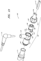
- FIG. 1A and 1B illustrate a perspective view and side view, respectively, of a gas delivery conduit 100 comprising an embodiment of a connector 105 for attaching a first tube 110 from a nasal cannula, face mask, intubation tube or other breathing device for a patient with a second tube 115 from a respirator, humidifier, breathing circuit, or other airflow device for providing gas to the patient.
- the connector can allow components of the gas delivery conduit 100 to be connected or disconnected from each other, thus facilitating disconnection and reconnection of the breathing device and airflow device with potentially minimal disturbance to the patient or gas delivery system.
- a patient can receive humidified, oxygenated and/or pressurized gases through a nasal cannula 110 connected to the gas delivery tube 115 that in turn is connected to a humidifier or respirator.
- a nasal cannula 110 connected to the gas delivery tube 115 that in turn is connected to a humidifier or respirator.
- the following disclosure refers to embodiments of the connector for connecting a nasal cannula with a gas delivery tube (e.g., for providing oxygen), but references to such embodiments are not intended to limit the disclosure and other embodiments are possible.
- gases are supplied to the patient by alternative patient interfaces, such as a nasal or full-face mask, or provided using alternative airflow sources.
- the connector 105 includes a terminal conduit connector 120 for receiving a nasal cannula 110, a source conduit connector 125 for receiving a gas delivery tube 115 and a connecting adapter 140 for connecting the conduit connectors.
- the source conduit connector 125 includes an optional sensor port 130 for receiving a sensor probe 135.
- the terminal conduit connector 120 and source conduit connector 125 are releasably connected by the connecting adapter 140.
- the gas delivery tube 115 is configured to connect with the source conduit connector 125 and the nasal cannula 110 is configured to connect with the terminal conduit connector 120, forming a gas conduit 100 for providing oxygen or other gases to a patient.
- the oxygen flows from the gas delivery tube 115 to the nasal cannula 110.
- apertures of components of the gas conduit proximal to the gas delivery tube 115 are referred to as source apertures while apertures proximal to the nasal cannula 110 are referred to as terminal apertures.
- a source aperture 145 of the source conduit connector 125 connects with the gas delivery tube 115, for example, by fitting over and/or around the gas delivery tube 115 to form a seal.
- the source conduit connector 125 may be releasably attached to the gas delivery tube 115 or permanently attached.
- the terminal aperture 150 of the source conduit connector 125 includes locking tabs 151 and/or alignment tabs 152 for receiving the connecting adapter 140.
- the locking tabs are configured to lock with locking recesses 154 formed on fingers 153 of the connecting adapter 140, thereby forming a releasable seal.
- the alignment tabs 152 are configured to cause the connecting adapter 140 to rotate within the terminal aperture 150 if the locking tabs are misaligned with the locking recesses when inserted into the terminal aperture 150.
- the alignment tabs cause the connecting adapter 140 to rotate until the locking tabs and locking recess are aligned.
- the recesses 154 are holes extending through the fingers 153 and configured to perform the same function as the recesses 154.
- the locking tabs are configured to engage with the locking recesses 154 with an audible click in order to provide positive feedback that a connection has been fully made.
- a click can be generated, in one embodiment, when the fingers 153 are biased as they pass over the locking tabs and then generate a click when the locking recesses 154 snap-fit over the locking tabs.
- Audible clicks can also be generated in other ways, such as when other components engage with each other.
- a source aperture 155 of the terminal conduit connector is configured to receive the connecting adapter 140 to form a rotatable connection.
- ridges formed within the terminal conduit connector are adapted to lock with a channel 160 formed on the circumference of the connecting adapter 140.
- the terminal conduit connector 120 and connecting adapter 140 are able to rotate relative to each other by allowing the ridges to rotate along the channel 160.
- raised edges or collars along a terminal and source apertures of connecting adapter 140 prevent or inhibit disconnection of the terminal conduit connector 120 from the connecting adapter 140.
- the terminal conduit connector 120 can include a terminal aperture configured to receive a cannula tube of a nasal cannula 110.
- the terminal aperture 165 can include two openings for receiving a double conduit cannula tube. Each conduit can connect to a prong for insertion into a patient's nostril.
- the nasal cannula 110 can be releasably attached to the terminal conduit connector 120 or permanently attached.
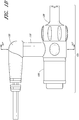
- FIG. 1B illustrates a side view of the connector 105.
- the source conduit connector 125 is connected to the terminal conduit connector 120.
- the sensor probe 135 is connected to the connector 105 via the sensor port 130.
- Axis 167 illustrates the cross-section along which FIG. 6 is taken.
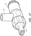
- FIG. 1C illustrates a perspective view of another connector embodiment having other embodiments of the source conduit connector 125, the terminal conduit connector 120 and the connecting adapter 140 (hidden in this view). This embodiment shares many of the structures and features discussed above with respect to FIG. 1A , such as the sensor port 130.
- FIG. 2A illustrates a perspective view of the terminal aperture 150 side of the source conduit connector 125 of FIG. 1A .
- the source conduit connector 125 includes a substantially cylindrical tube having a terminal aperture 150 and a source aperture 145 ( FIG. 1A ).
- the source conduit connector 125 can also include an optional sensor port 130 for receiving a sensor probe 135.
- the sensor port 130 includes a substantially cylindrical tube extending perpendicularly from the source conduit connector 125.
- the tube is perpendicular to the body of the conduit connector 125.
- the tube is substantially perpendicular but may be angled by a few degrees (e.g., less than 5, 10, or 15 degrees) from perpendicular.
- the tube is angled by more than 15 degrees.
- One or more finger grooves 202 can be formed on the outside surface of the source conduit connector 125 in order to provide additional purchase or friction to a user, for example, for connecting or disconnecting the connector 105 ( FIG. 1A ) components.
- two finger grooves 202 can be placed on opposite sides of the source conduit connector 125.
- the source conduit connector 125 includes locking tabs 151 and alignment tabs 152 for receiving the connecting adapter 140 ( FIG. 1A ).
- two locking tabs 151 are formed on the interior surface of the source conduit connector 125 and configured to lock with locking recesses formed on the connecting adapter 140.
- the locking tabs 151 can be formed opposite each other.
- the alignment tab 152 is formed by a single, continuous protrusion or ridge formed on the interior surface of the source conduit connector 125.
- the single continuous protrusion or ridge alternates from a first distance toward the terminal aperture 150 of the source conduit connector 125 to a second distance away from the terminal aperture 150.
- the continuous protrusion or ridge can form a bowl or saddleback shape, with alternating valleys 215 and apexes 220.
- the apexes 220 are configured to direct fingers of the connecting adapter 140 into the valleys 215, wherein the locking tabs 151 can lock with locking recesses on the fingers.
- the apexes 220 can be sloped towards the valleys 215, such that the fingers, when inserted into the source conduit connector 125, are directed by the slope of the apexes 220 towards the valleys 215.
- the source conduit connector 125 includes an optional sensor port 130 for receiving a sensor probe 135.
- the sensor port 130 is positioned near the terminal aperture 150 or substantially adjacent to the aperture 150. By placing the sensor port 130 close to the aperture 150, the sensor probe 135 is able to sample gas flow closer to the patient. Such sampling can provide more accurate measurement of the condition of the gas flow that the patient receives. For example, if the sensor probe 135 is positioned further away from the patient, there may be a greater difference between the sampled gas flow and the gas flow inhaled by the patient.
- the airflow source 115 can include a heating element that warms the air, but as the airflow leaves the source 115, the temperature of the airflow can cool rapidly.
- the sensor should be placed as close to the patient as possible to obtain more accurate results.
- due to condensation, humidity changes occur very rapidly. Again, the closer the sensor can be placed to the patient, the more accurate the sensor measurements will be.
- similar benefits can be obtained without the optional sensor port 130 by positioning the sensor probe 135 close to the aperture 150 or towards the patient or nasal cannula 110. For example, this can be done by replacing the sensor port with an integrated sensor as described below.
- the sensor probe 135 is positioned into the gas flow within the gas delivery conduit 100 in order to sample, measure and/or analyze the gas flow.
- the sensor probe 135 can include any type of sensor(s), such as, for example, a temperature sensor, thermistor, flow meter, oxygen (O 2 ), carbon dioxide (CO 2 ), nitric oxide and/or humidity sensor.
- the sensor probe 135 can be reusable or disposable and can be detachable or integrated with a conduit connector.
- the sensor probe 135 can be connected to a monitoring system having one or more processors for analyzing measurements and can communicate with the monitoring system via a cable or wirelessly.
- the monitoring system can include a display or other output device (e.g., speaker, alarm or wireless transmitter) for displaying measurements or generating an alarm.
- the sensor probe 135 and/or monitoring system can include a memory device such as, for example, an electrically erasable programmable read only memory (EEPROM), erasable programmable read only memory (EPROM), flash memory, nonvolatile memory or the like.
- the sensor probe 135 can include a plurality of conductors for communicating signals to and from its components, including sensing component conductors and memory device conductors.
- the sensor port 130 is configured to accept different types of sensor probes 135, allowing sensor probes 135 to be changed based on the current use.
- a humidity sensor can be used during humidity therapies while an oxygen sensor can be used during oxygen therapies.
- the alignment tabs 152 can be formed by multiple protrusions or discontinuous ridges rather than a single continuous protrusion.
- two disconnected apexes 220 can be formed on opposite sides of the interior surface of the source conduit connector 125.
- the source conduit connector 125 can include either alignment tabs 152 or locking tabs 151.
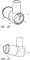
- FIGS. 2B-2G illustrate various views of the source conduit connector 125 of FIG. 1C .
- This embodiment shares many of the structures and features discussed above with respect the source conduit connector 125 of FIG. 1A .
- FIG. 2B illustrates a perspective view of the source conduit connector 125 facing the terminal aperture 150 and showing, formed on the interior surface, a locking tab 151 and the alignment tab 152.
- FIG. 2C illustrates a side perspective view of the source conduit connector 125 showing the source aperture 145.
- FIG. 2D illustrates a side view of the source conduit connector 125 showing the source aperture 145, the terminal aperture 150, a finger groove 202, and the sensor port 130.
- FIG. 2E illustrates a cross-sectional view of the source conduit connector 125 taken along the indicated line in FIG. 2D.
- FIG. 2E shows the source aperture 145, the terminal aperture 150 and, on the interior surface, the locking tabs 151 and the alignment tab 152.
- FIG. 2F illustrates a terminal aperture 150 facing view of the source conduit connector 125 showing the sensor port 130 and, on the interior surface, the locking tabs 151 and the alignment tab 152.
- FIG. 2G illustrates a sensor port aperture facing view of the source conduit connector 125 showing the aperture of the sensor port 130 opening into the body of the source conduit connector 125.
- the sensor port 130 is shown substantially adjacent and perpendicular to the terminal aperture 150, away from the source aperture 145.
- FIGS. 3A and 3B illustrate perspective views of the connecting adapter 140 of FIG. 1A from a source aperture 305 side and a terminal aperture 310 side, respectively.
- the connecting adapter 140 includes a substantially cylindrical tube having two locking fingers 153 extending from the source aperture 305.
- the locking fingers 153 can be spaced apart to form an insertion aperture 312 for the sensor probe 135 ( FIG. 1A ) to fit between the fingers 153.
- the insertion aperture 312 can provide an opening through which a portion of the sensor probe 135 extends into the gas delivery conduit 100, in order to sample airflow from within the gas delivery conduit 100 ( FIG. 1A ).
- the insertion aperture 312 can also allow the sensor probe 135 to be positioned closer to the nasal cannula 110 ( FIG.
- the insertion aperture 312 allows the sensor probe 135 to be placed closer to the patient while simultaneously allowing a portion of the connecting adapter 140 to engage with the source conduit connector 125 ( FIG. 1A ).
- the sensor probe 135 may have to be placed past the ends 314 of the connecting adapter 140, further away from the nasal cannula 110, which can eliminate, inhibit or reduce some of the potential benefits discussed above for placing the sensor probe 135 closer to the patient.
- each locking finger 153 includes a locking recess 154 formed on the outer surface of the locking finger 153.
- the locking recesses 154 are configured to lock with the locking tabs of the source conduit connector 125.
- the locking fingers 153 include a flexible or semi-rigid material such that sufficient longitudinal force can cause the locking recesses 154 to pass over locking tabs 151 of the source conduit connector 125, thereby releasing the connecting adapter 140 from the source conduit connector 125.
- pushing the connecting adapter 140 into the source conduit connector 125 (on assembly or connection) or pulling out the adapter 140 (on disconnection) can cause the locking tabs of the source conduit connector 125 to engage or disengage with the locking recesses 154 of the locking finger 153.
- the connecting adapter 140 can include a locking channel 160 formed along the circumference of its external surface.
- the edges of the channel are bounded by collars 320, 325 at the source and terminal apertures. Ridges, such as on the terminal conduit connector 120 ( FIG. 1A ), can lock into the channel 160.
- the collars can prevent or inhibit disconnection of the ridges due to longitudinal force (e.g., force along the conduit 100 axis), while allowing the ridges to rotate along the locking channel 160.
- the terminal collar 320 includes a flexible or semi-rigid material such that sufficient longitudinal force can cause the ridges to pass over the collar 320 and cause the connecting adapter 140 to release from the terminal conduit connector 120.
- the connecting adapter 140 can have one or more optional spines 330 formed longitudinally on its interior surface.
- the spines 330 can provide rigidity to the connecting adapter and, in one embodiment, are spaced evenly along the interior circumference of the connecting adapter 140.
- the spines 330 are tapered and can provide greater rigidity on one end compared to the other.
- the source aperture 305 side of the connecting adapter 140 may need greater flexibility in order to attach and/or detach with the source conduit connector 125 and the spines 330 can taper (in height or width) towards the source aperture 305.
- the connecting adapter 140 can have one, two, three, four or more spines 330.
- other types of connection mechanisms can be used, such as, for example, a threaded mechanism, pinion mechanism, friction fit, circlip and/or adhesive or other chemical connector.
- different types of connecting adapters can be provided for connecting different types of conduit connectors.
- a respirator conduit can have a different type of source conduit connector than a humidifier conduit.
- the connecting adapter By changing the connecting adapter, the same nasal cannula can be connected to either the respirator conduit or the humidifier conduit.
- the nasal cannula does not have to be changed, thereby minimizing patient discomfort by eliminating or reducing the need to replace the nasal cannula attached to the patient.
- different types of terminal conduit connectors can be connected to the same type of source conduit connector by changing adapters.
- the nasal cannula can be replaced with a face mask having a different terminal conduit connector type by attaching it to the same humidifier by using a different connecting adapter.
- the interchangeability of the connectors can potentially speed up the setup of gas delivery conduits, which can be particularly beneficial in emergency situations.
- FIGS. 3C-3G illustrate various views of the connecting adapter 140 of FIG. 1C .
- This embodiment shares many of the structures and features discussed above with respect the connecting adapter 125 of FIG. 1A .
- FIG. 3C illustrates a top view of the connecting adapter 140 showing two locking fingers 153 extending from the body of the connecting adapter 140 and two locking recesses 154 formed on the exterior surface of the locking fingers 153.
- raised strips 350 form the bottom boundary of the recesses 154 on the respective locking fingers 153.
- Each raised strip 350 can provide additional support and/or rigidity to each locking recess 154, allowing a more secure connection of the locking recesses with the corresponding locking tabs.
- FIG. 3D illustrates a side view of the connecting adapter 140 showing a locking finger 153 extending from the body of the connecting adapter 140, a locking recess 154 formed on the exterior surface of the locking fingers, and the locking channel 160 formed along the circumference of the adapter's external surface.
- the locking finger 153 widens from its end 314 to its base 340. By widening at its base, where the finger 153 connects with the body of the connecting adapter 140, the strength of the locking finger 153 is enhanced, making it more difficult to deform the locking finger 153 and disconnect it when it is engaged with the locking tab 151 of the source conduit connector 125. Additionally, the raised strip 350 can also enhance the strength of the locking finger 153.
- FIG. 3E illustrates a perspective view of the terminal conduit connector 120 facing aperture of the connecting adapter 140.
- FIG. 3E shows the locking finger 153, the locking recess 154, the locking channel 160 and the spines 330 formed longitudinally on the interior surface of the connecting adapter.
- FIG. 3F illustrates a front facing view of an aperture of the connecting adapter 140 facing the terminal conduit connector 120.
- FIG. 3G illustrates a front facing view of an aperture of the connecting adapter 140 facing the source conduit connector 125.
- the spines 330 are shown formed on the interior surface of the adapter 130.
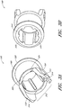
- FIGS. 4A and 4B illustrate a perspective view of the source aperture 155 side of the terminal conduit connector 120 and a top view of the terminal conduit connector 120 of FIG. 1A .
- FIG. 4A illustrates the terminal conduit connector 120 without the connecting adapter 140 inserted
- FIG. 4B illustrates the terminal conduit connector 120 with the connecting adapter 140.
- the terminal conduit connector 120 includes ridges 405 spaced along the circumference of the interior surface of the terminal conduit connector 120.
- the ridges 405 are protrusions or tabs formed longitudinally by surrounding cutouts, or axially, along the terminal conduit connector 120. The ridges 405 and surrounding cutouts can decrease frictional engagement with the connecting adapter 140, thereby improving rotatability.
- the ridges 405 can be tapered, in width or in height. The tapering can allow insertion of the connecting adapter 140 to be accomplished with less force while requiring more force for removing the connecting adapter 140 as a larger surface area of each locking tab engages with the terminal collar 320 ( FIG. 3A ) of the connecting adapter 140.
- a locking groove 410 is formed along the circumference of the terminal conduit connector 120 and is configured to engage with the terminal collar 320 of the connecting adapter 140, thereby increasing the longitudinal force needed to disengage the terminal conduit connector 120 from the connecting adapter 140.
- the terminal conduit connector 120 includes a terminal aperture 165 on the terminal conduit connector 120 configured to receive a cannula tube of a nasal cannula 110 ( FIG. 1A ).
- the terminal aperture 165 can include two openings for receiving a double conduit cannula tube, wherein each conduit connects, on the opposite end of the tube, to a prong for insertion into a patient's nostril.
- the openings are optionally surrounded by an angled surface configured to funnel airflow into the double conduit cannula tube, which can improve airflow.
- the terminal conduit connector 120 can also include one or more finger grooves 415 formed on the outside surface of the terminal conduit connector 120 in order to provide additional purchase or friction to a user, for example, for connecting or disconnecting the connector 105 ( FIG. 1A ) components.
- multiple finger grooves 415 are spaced along the outside circumference of the terminal conduit connector 120.
- the locking tab 405 is a single, continuous ridge.
- the ridges 405 are formed perpendicular or angled relative to the axis of the terminal conduit connector 120.
- the locking groove 410 is not included.
- the aperture 165 can be a single opening.
- the aperture 165 can be configured to receive a single conduit to a face mask.
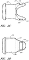
- FIGS. 4C-4G illustrate various views of the terminal conduit connector 120 of FIG. 1C .
- This embodiment shares many of the structures and features discussed above with respect the terminal conduit connector 120 of FIG. 1A .
- FIG. 4C illustrates a side view of the terminal conduit connector 120 showing the terminal apertures 165 for receiving nasal cannula and the source aperture 155.
- a first portion of the body of the terminal conduit connector 120 that receives the connecting adapter 140 is a first height.
- a second portion of the body of the terminal conduit connecter 120 that receives the nasal cannula is a second, lower height.
- FIG. 4D illustrates a top down view of the terminal conduit connector 120 showing the terminal apertures 165 and the source aperture 155.
- the first portion of the body of the terminal conduit connector 120 has a first width while the second portion of the body has a second, narrower width.
- FIG. 4E illustrates a facing view of the terminal apertures 165.
- FIG. 4F illustrates a facing view of the source aperture 155 that shows the ridges 405 spaced along the circumference of the interior surface of the terminal conduit connector 120.
- FIG. 5 illustrates a longitudinal cross-sectional view of the connector 105 embodiment of FIG. 1A .
- FIG. 5 illustrates the terminal collar 320 of the connecting adapter 140 engaged with the locking groove 410 of the terminal conduit connector 120.
- a portion of the sensor probe 135 fits between the fingers 153 of the connecting adapter.
- FIG. 5 illustrates the fingers 153 fitting against the alignment tabs 152.
- the source conduit connector 125 includes an inner cylinder 505 within an outer cylinder 510, forming an insertion groove 515 for receiving the delivery tube 115 ( FIG. 1A ).
- pressure from the inner and outer cylinders maintains a pressure fit with the delivery tube 115, keeping the delivery tube 115 connected to the source conduit connector 125.
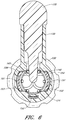
- FIG. 6 illustrates a cross-section taken along an axis 167 of FIG. 1B facing towards the nasal cannula 110 ( FIG. 1A ) and illustrates the engagement of the connecting adapter 140 with the source conduit connector 125.
- the source conduit connector 125 and terminal conduit connector 120 are attached via the connecting adapter 140.
- the locking tabs 151 formed on the interior surface of the source conduit connector 125 engage with the recesses 154 on the fingers 153 of the connecting adapter 140.
- the engagement inhibits longitudinal movement of the adapter and limits accidental disengagement of the connector 105 ( FIG.1A ).
- the alignment tabs 152 can guide the fingers 153 into position for engagement.
- the sensor port 130 provides the sensor probe 135 with access to the airflow within the gas delivery conduit 100 ( FIG. 1A ). Airflow from the airflow source passes by the sensor probe 135 before exiting through the terminal aperture 165 of the terminal conduit connector 120.
- the connector 105 does not necessarily fall within the scope of the present invention, the latter being exclusively defined by the appended claims.
- the connector 105 does not include a connecting adapter 140 or another component (however, an arrangement in which the connector 105 does not include a connecting adapter 140 does not fall within the scope of the present invention as defined by the appended claims).
- elements such as tabs, protrusions, recesses, channels or grooves, are located on different components.
- first element of a connecting mechanism e.g., protrusion or tab
- second element of the connecting mechanism e.g., recess, channel or groove
- the locations of the elements can be switched, with the first element on the second component and the second element on the first component.
- certain elements may not be included.
- a first connector component can be configured to attach over a second connector component while in another arrangement, the second connector component can be configured to attach over the first connector component.
- connections can be used to attach the components of the connector 105.
- adhesives or other chemical agents may be used to permanently affix some components together.
- different mechanical connection mechanisms can be used, such as a snap fit, thread, friction fit or circlip.
- the components of the connector 105 can be composed of various types of flexible, semi-rigid, or rigid materials.
- the connecting adapter 140 and source conduit connector 125 can include polypropylene materials and the terminal conduit connector 120 can include of THERMOLAST materials.
- Other materials such as plastics, thermoplastics, silicone, glass-filled nylon, metal, spring steel, polycarbonate, PVC, polyethylene, rubber (e.g., natural or vulcanized), polyurethane, or the like can be used.
- the connecting adapter 140 includes ABS plastic
- the source conduit connecter 125 includes polypropylene
- the terminal conduit connector 120 includes thermoplastic elastomer.
- some of the releasable connection mechanisms can be stronger than others.
- the connection formed by the connecting adapter 140 with the source conduit connector 125 is weaker than the connection formed by the connecting adapter 140 with the terminal conduit connector 120.
- pulling apart the conduit connectors 120, 125 can cause the connecting adapter 140 to separate from the source conduit connector 125 while remaining connected to the terminal conduit connector 120.
- This configuration can facilitate changing patient interfaces by allowing another patient interface to be easily or quickly attached to the source conduit connector 125.
- the connecting adapter 140 can be configured to remain connected with the source connecting conduit 125.
- the connections of the connector 105 are configured to allow a quick connect or quick release of the connector components
- the components can be configured to connect or release with a single motion (e.g., when pushed together or pulled apart).
- the components can be configured to self-align during engagement, such that the connecting mechanisms of the components align automatically.
- the connections of the connector 105 with the gas delivery tube 115 ( FIG. 1A ) and/or the nasal cannula 110 can be stronger relative to other connections (e.g., the connections with the connecting adapter 140), such that longitudinal force applied to the gas delivery conduit 100 causes those other, weaker connections to disconnect first.
- the connections with the gas delivery tube 115 and/or the nasal cannula 110 are permanent or semi-permanent, in order to eliminate or reduce accidental disconnections.
- the terminal aperture 165 includes a single opening, two openings, or three or more openings. There can be one, two, or more than two finger grooves 415 ( FIG. 4A ) on the outside.
- the gas delivery conduit 100 or portions of the conduit can be attached to the patient via a lanyard (e.g., around the patient's neck), clip, or other fastening mechanism.
- the seals formed by the components can be air-tight or can allow some air to leak.
- components of the connector 105 can be colored differently to indicate a size of the connector. For example, red can indicate adult sized connectors while blue can indicate infant connectors.
- the gas deliver conduit 100 can include one or more spring tube sections, which can increase flexibility.
- the components of the connector 105 can be formed in various sizes, depending on its intended use. For example, connectors for gas delivery conduits 100 for children or infants can be smaller than connectors for gas delivery conduits 100 for adults.
- the source conduit connector 125 has an outer diameter in the range of 5-30mm, though this diameter may be larger or smaller in other embodiments. In one embodiment, the outer diameter is about 15mm.
- the other connector components 105 can be sized correspondingly to the source conduit connector 125. For example, the other components may be sized approximately the same as the source conduit connector 125 in order to engage with it.
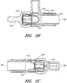
- FIG. 7 illustrates an alternate connector embodiment 700 of the connector of FIG. 1A .
- the terminal conduit connector 705 includes dual ball and socket connections 710 for individually connecting cannula tubes to the terminal conduit connector.
- the ball and socket connections 710 can be moved independently of each other. This can allow the cannula tubes to be untwisted or untangled separately, thereby facilitating adjustment of the nasal cannula.
- the greater freedom of movement provided by the ball and socket connections 710 can potentially provide similar degrees of adjustments while allowing cannula tubes of shorter length to be used.
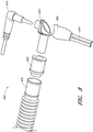
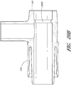
- FIG. 8 illustrates an alternate connector embodiment 800 that does not fall within the scope of the present invention as defined by the appended claims.
- the terminal conduit connector 805 and sensor probe 810 connects substantially perpendicularly to the source conduit connector 815.
- the source conduit connector 815 connects to a swivel tube 820 that in turn connects to a gas delivery tube 825.
- the sensor probe, terminal conduit connector and source conduit connector are rotatably attached to the gas delivery tube via the swivel tube 820, the connector can be laid flat on a patient's bed, potentially increasing patient comfort or keeping the connector out of the way.
- the connector 800 is shaped to form a substantially 90 degree angle, thereby redirecting airflow over the sensor probe 810 and into the nasal cannula 830.
- This redirection of the airflow can advantageously allow the sensor probe 810 to detect disconnection of the terminal conduit connector 805 by detecting a change in the airflow.
- the sensor probe 810 can detect a change in the direction, speed or compositions (e.g., humidity or temperature) of the airflow and determine that the terminal conduit connector 805 is no longer attached to redirect the airflow.
- FIG. 9 illustrates another alternate connector embodiment 900 that does not fall within the scope of the present invention as defined by the appended claims.
- the terminal conduit connector 905 can connect either substantially perpendicularly or substantially straight with the source conduit connector 910.
- the dual orientation of the terminal conduit connector 905 can provide greater flexibility in adjusting the nasal cannula 920.
- the source conduit connector 910 can include an aperture 930 through which the sensor probe 925 can partially extend into the terminal conduit connector 905, thus placing the sensor probe 925 closer to the entry point of the airflow into the cannula.
- the aperture 930 is notched to allow the sensor probe 925 to extend past the aperture 930. This can allow the sensor probe 925 to gather more accurate measurements of the temperature, humidity or other parameter of the gases inhaled by the patient.
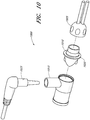
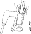
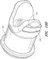
- FIG. 10 illustrates another alternate connector embodiment 1000 that does not fall within the scope of the present invention as defined by the appended claims.
- a terminal conduit connector 1005 connects to a connecting adapter 1010, which connects to a source conduit connector 1015.
- the connecting adapter 1010 includes a collar 1020 having a greater diameter than the adjacent terminal conduit connector and source conduit connector.
- the collar 1020 can be colored to indicate sizing information for the connector 1000.
- the collar 1020 can also provide a better friction hold to a user, thereby allowing a shorter connector to provide similar amount of frictional grip, which can facilitate the attachment and/or detachment of the connector components.
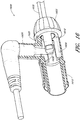
- FIG. 11A and FIG. 11B illustrate another alternate connector embodiment 1100 that does not fall within the scope of the present invention as defined by the appended claims.
- a terminal conduit connector 1105 fits within a source conduit connector 1110, while a threaded cap 1115 fits over the terminal conduit connector 1105 and engages with a threaded end 1120 of the source conduit connector.
- the threaded cap 1115 engages with a collar of the terminal conduit connector 1125 and keeps the terminal conduit connector pressed against the source conduit connector.
- Fins 1126 formed on the body of the terminal conduit connector 1105 can provide a space between the exterior of the terminal conduit connector 1105 and the interior of the source conduit connector 1110.
- the threaded cap 1115 only engages with some of the thread flutes on the threaded end 1120 of the source conduit connector. For example, if the threaded end 1120 has six thread flutes, the thread cap 1115 is configured to engage with only three of the flutes, leaving the other three thread flutes vacant.
- the partial engagement of the threads can allow condensate collecting in the connector to escape out along the vacant threads, along an outflow path 1135, thereby preventing or inhibiting condensate from entering the cannula 1130.
- the outflow path 1135 or venting channel can be partly formed by the space 1137 between the exterior of the terminal conduit connector 1105 and the interior of the source conduit connector 1110.
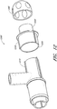
- FIG. 12 illustrates another alternate connector embodiment 1200 that does not fall within the scope of the present invention as defined by the appended claims.
- a terminal conduit connector 1205 connects to a connecting adapter 1210, which connects to a source conduit connector 1215.
- the connecting adapter includes an end 1220 for connecting with the terminal conduit connector 1205, for example, via threads or friction fit.
- the source aperture 1225 of the connecting adapter 1210 fits over the source conduit connector 1215.
- FIG. 13 illustrates another alternate connector embodiment 1300 that does not fall within the scope of the present invention as defined by the appended claims.
- a terminal conduit connector 1305 connects to a source conduit connector 1310.
- Locking tabs 1315 formed on a connecting end of the terminal conduit connector engage with other locking tabs within the source conduit connector 1310. Twisting the terminal conduit connector 1305 relative to the source conduit connector 1310 can cause the locking tabs 1315 to disengage, allowing the connector 1300 to be separated.
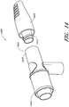
- FIG. 14 illustrates another alternate connector embodiment 1400 that does not fall within the scope of the present invention as defined by the appended claims.
- a terminal conduit connector 1405 connects to a source conduit connector 1410.
- a locking thread 1415 formed on a connecting end of the terminal conduit connector engages with the source conduit connector. Twisting the terminal conduit connector 1405 relative to the source conduit connector 1410 can cause the locking thread 1415 to disengage, allowing the connector 1400 to be separated.
- one side of the conduit connector 1410 can be configured to engage with another component using a unique or proprietary connection mechanism while the other side of the conduit connector 1410 uses a generic or standard connection mechanism.
- the generic connection can allow connection to a variety of components, made by different manufacturers. Meanwhile, the proprietary connection only allows connection to components of a single or a select set of manufacturers. Providing two different types of connectors can be beneficial in situations when one component requires greater accuracy than another and requiring use of a particular component allows components with known or predetermined characteristics to be used. Meanwhile, the generic connection can provide greater interoperability.
- the generic connection 1420 attaches using a friction fit while the proprietary connection 1425 connects with the locking thread 1415.
- FIG. 15 illustrates another alternate connector embodiment 1500 that does not fall within the scope of the present invention as defined by the appended claims.
- a terminal conduit connector 1505 connects a source conduit connector 1510.
- the edge of the source conduit connector 1510 can engage with a locking groove 1512 on the terminal conduit connecter 1505.
- An O-ring seal 1515 creates a seal between the terminal conduit connector and source conduit connector.
- a sensor port 1520 is formed on the source conduit connector away from the source conduit connector's connection with the terminal conduit connector.
- FIG. 16 illustrates another alternate connector embodiment 1600 that does not fall within the scope of the present invention as defined by the appended claims.
- a terminal conduit connector 1605 connects with a connecting adapter 1610, which connects with a source conduit connector 1615.
- the connecting adapter 1610 includes three fingers 1620 for engaging with the source conduit connector 1615.
- the fingers 1620 can be spaced apart to create an insertion aperture 1630 for a sensor probe 1605 to fit between two of the fingers 1620.
- the insertion aperture 1630 allows the sensor probe 1605 to be positioned closer to the nasal cannula 1635. For example, without the insertion aperture 1630, the sensor probe 1605 may have to be placed past the ends of the connecting adapter 1610, further away from the nasal cannula 1635.
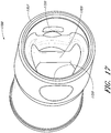
- FIG. 17 illustrates an embodiment of a conduit connector 1700 having an integrated sensor probe 1705.
- the sensor probe 1705 is positioned to fit into an insertion aperture formed by two fingers of a connecting adapter (e.g., connecting adapter 140 of FIG. 1 ). By fitting into an insertion aperture, the sensor probe 1705 can be positioned closer to a nasal cannula. In the illustrated embodiment, the sensor probe 1705 is positioned at approximately the same distance from an aperture 1707 of the conduit connector 1700 as locking tabs 1720. The sensor probe 1705 fits between the fingers of the connecting adapter when the fingers engage with the locking tabs 1720. In one embodiment, the conduit connector 1700 does not have a sensor port.
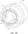
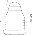
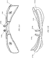
- FIGS. 18A-18C illustrate different views of an embodiment of a conduit connector 1800 having a receptacle for a detachable sensor probe.
- the receptacle includes channels 1805, 1810 for receiving the sensor probe.
- the channels 1805, 1810 can extend partially or wholly within an interior surface of the conduit connector 1800.
- the sensor probe can be plate-shaped, rectangular shaped, oval shaped, diamond shaped or any other shape configured to be received by the receptacle.
- the sensor probe comprises alignment tabs configured to engage with the channels 1805, 1810.
- the alignment tabs can be configured to position the sensor probe into a predetermined position within the conduit connector 1800, such as a position where sensor measurements can be more effectively taken or a position between an insertion aperture formed by one or more locking fingers of a connecting adapter.
- the receptacle can include a catch, notch, tab, wall or other structure for locking or securing the sensor probe in place once the predetermined position is reached.
- the receptacle can include other structures for receiving and/or securing the sensor probe in addition or alternatively to the channels 1805, 1810.
- the receptacle can comprise ridges configured to engage with channels on the sensor probe.
- the conduit connector 1800 can also include one or more locking tabs 1820.
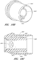
- FIG. 18B illustrates a back perspective view
- FIG. 18C illustrates a cross-sectional view of the embodiment of FIG. 18A .
- an insertion groove for a second conduit such as a hose or deliver tube
- a second conduit such as a hose or deliver tube
- the outer wall 1825, 1830 and an inner wall 1827, 1832 of the conduit connector 1800 are formed by a space between the outer wall 1825, 1830 and an inner wall 1827, 1832 of the conduit connector 1800.
- end of the outer wall extends past an end 1822 of the inner wall.
- the inner and outer wall may be the same length or the inner wall may extend past the outer wall.
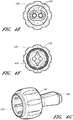
- FIGS. 19A-19B illustrate an alternate connector adapter embodiment configured to connect with the source conduit connector embodiment of FIGS. 20A-20B .
- FIG. 19A illustrates a side view of the connecting adapter facing one of two locking fingers 153 and its locking recess 154.
- a channel 160 formed on the body of the connecting adapter provides an engagement surface for a corresponding terminal conduit connector, as shown in various embodiments of the disclosure.
- the locking recess 154 extends across the locking finger 153 to provide engagement with an annular locking ring on the source conduit connector embodiment of FIGS. 20A-20B .
- FIG. 19B illustrates a perspective view of the connecting adapter of FIG. 19A showing the locking fingers 153 and its locking recess 154.
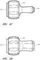
- FIGS. 20A-20B illustrate an alternate source conduit connector 125 embodiment having an annular ring for attaching to the alternate connector adapter embodiment of FIGS. 19A-19B .
- FIG. 20A illustrates a perspective view of the source conduit connector facing the terminal aperture 150 side.
- an annular locking ring 2005 formed by a raised strip running circumferentially within the body of the source conduit connector.
- the locking recesses 154 of the connecting adapter of FIGS. 19A and 19B are configured to engage with the annular locking ring 2005 when the connecting adapter is inserted into the source conduit connector.
- FIG. 20B illustrates a cross sectional view taken along the indicated cross section line in FIG. 20A .
- the cross-sectional view shows the annular locking ring 2005 formed on the interior surface of the source conduit connecter.
- FIGS. 21A-D illustrate different views of an embodiment of a nasal cannula 2100 that connects to an airflow source via the various connector embodiments discussed in the disclosure.
- the nasal cannula is for infants.
- FIG. 21A illustrates a top perspective view of the patient facing side of the nasal cannula 2100.
- the nasal cannula 2100 includes two prongs 2105a, 2105b that fit into the patient's nostrils.
- Airway tubes 2110 extend from the prongs and connect to an air source (e.g., via the connector 105 of FIG. 1A ).
- FIG. 21B illustrates a top perspective view of the external side of the nasal cannula 2100 facing away from the patient.
- FIG. 21B shows the two prongs 2105a, 2105b and two airway tubes 2110a, 2110b connected to the two prongs.
- FIG. 21C illustrates a side view of the nasal cannula 2100 showing one of the prongs 2105 and one of the airway tubes 2110.
- FIG. 21D illustrates a bottom view of the nasal cannula 2100 showing the two prongs 2105a, 2105b and the two airway tubes 2110a, 2110b connected to the two prongs.
- connection mechanism in the terminal conduit connector 120 can be implemented by the source conduit connector 125 and/or the connection mechanism of the source conduit connector 125 can be implemented by the terminal conduit connector 120.
- the sensor port 130 can be located on the terminal conduit connector 120 rather than the source conduit connector 125.
- Some features can be implemented by a different component (e.g., the terminal conduit connector 120, source conduit connector 125 or connecting adapter 140) rather than in the component described as implementing the feature in the above disclosure.
Description
- This disclosure relates to the field of connectors for gas delivery hoses.
- A nasal cannula is a device used to deliver supplemental oxygen, other gases, or airflow to a patient or person for treatment or for aiding respiration. Typically, the cannula includes a plastic tube and a set of two prongs which are placed in the nostrils. Oxygen or other gases can flow from these prongs.
- The nasal cannula can be connected to an oxygen tank, a portable oxygen generator, a wall connection in a hospital via a flowmeter, or other gas source. Nasal cannulas can supply oxygen to a patient at rates that depend partly on size. For example, infant or neonatal nasal versions can carry less oxygen and can have smaller prongs than adult versions. The cannula can be used to supply oxygenated air, humidified air or other gas mixtures.
- Some other prior art conduit connectors for patient breathing devices are known from the documents
US 2006/107960 A1 ,EP 1 314 446 A2 ,WO 2007/143792 A1 ,US 5 937 851 A ,WO 03/082406 A2 US 6 915 705 B1 andUS 2008/264413 A1 . - It is an object of the present invention to provide a connector for gas delivery hoses which will go at least some way towards addressing the foregoing problems or which will at least provide the public with a useful choice.
- The present invention provides therefore a connector adapter as defined in claim 1, a connector assembly as defined in claim 11, and a gas delivery conduit as defined in claim 16. Further preferred embodiments of the invention are defined in the dependent claims.
- Further aspects and advantages of the present disclosure will become apparent from the ensuing description which is given by way of example only.
- In some situations, a nasal cannula is used to provide humidified airflow or oxygen therapy. In order to monitor the airflow being received by the patient, a sensor probe can be used. However, the further the distance of the probe from the prongs that provide air to the nostrils, the greater the potential variance between the sampled air and the air inhaled by the patient. Thus, a conduit connector that places the sensor probe in the airflow closer to the patient can enhance the accuracy of the measurements taken.
- As a nasal cannula or other breathing device can be connected to a patient for extended periods of time, the nasal cannula can generate discomfort for the patient or otherwise begin to perform sub-optimally. For example, as the patient moves around in a hospital bed, the nasal cannula tubing can become tangled or twisted, thereby causing the patient discomfort or limiting the airflow within the cannula. Thus, a design that facilitates adjustments of the nasal cannula can provide greater comfort to the patient or improve performance.
- At times, the nasal cannula or an airflow source may need to be removed or replaced. If detaching the nasal cannula from the airflow source is difficult or time consuming, detaching the nasal cannula may cause significant discomfort for the patient. Further, in emergencies, a slow or difficult connection mechanism can potentially place the patient's health in danger. Thus, a conduit connector that provides a "quick-connect" or "quick-release" feature that facilitates attachment and detachment of the nasal cannula from an airflow source, as well as facilitating interchangeability of components, can provide greater comfort and/or safety.
- In order to address the issues discussed above, aspects of the present disclosure include a connector or connector assembly for attaching a nasal cannula with a gas delivery hose. In an embodiment, the connector assembly includes a sensor port for a sensor probe. The sensor port is positioned near an end of a nasal cannula, towards the patient. In an embodiment, the connector is configured to allow the sensor to be placed closer to the patient's nostrils than previous connector parts allowed.
- Aspects of the present disclosure also include a self-aligning connector assembly configured to automatically align locking protrusions on a first component with locking recesses on a second component, wherein insertion of the second component within the first component causes the second component to rotate relative to the first component, thereby aligning the locking protrusions with associated locking recesses. In an embodiment, the connector is configured to advantageously allow the nasal cannula to rotate relative to the gas delivery hose. By allowing rotation, the connector enables a patient or healthcare provider to untangle or otherwise straighten the hose or the cannula, thereby increasing patient comfort.
- The term "comprising" as used in this specification means "consisting at least in part of". When interpreting each statement in this specification that includes the term "comprising", features other than that or those prefaced by the term may also be present. Related terms such as "comprise" and "comprises" are to be interpreted in the same manner.
- The invention consists in the foregoing and also envisages constructions of which the following gives examples only.
- Throughout the drawings, reference numbers may be re-used to indicate correspondence between referenced elements. The drawings are provided to illustrate embodiments of the disclosure described herein and not to limit the scope thereof.
-
FIG. 1A illustrates an exploded perspective view of a gas delivery conduit having a connector embodiment for attaching a first tube with a second tube, the connector having a source conduit connector, a terminal conduit connector and a connecting adapter; -
FIG. 1B illustrates a side view of the connector embodiment ofFIG. 1A ; -
FIG. 1C illustrates a perspective view of another connector embodiment having other embodiments of the source conduit connector, the terminal conduit connector and the connecting adapter; -
FIG. 2A illustrates a perspective view of the terminal aperture side of the source conduit connector ofFIG. 1A ; -
FIGS. 2B-2G illustrate various views of the source conduit connector ofFIG. 1C ; -
FIGS. 3A and 3B illustrate perspective views of the connecting adapter ofFIG. 1A from a source aperture side and a terminal aperture side, respectively; -
FIGS. 3C-3G illustrate various views of the connecting adapter ofFIG. 1C ; -
FIGS. 4A and4B illustrate a perspective view of a source aperture side of the terminal conduit connector and a top view of the terminal conduit connector ofFIG. 1A ; -
FIGS. 4C-4G illustrate various views of the terminal conduit connector ofFIG. 1C ; -
FIG. 5 illustrates a longitudinal cross-sectional view of the connector ofFIG. 1A ; -
FIG. 6 illustrates a cross-section taken along across an axis ofFIG. 1B and illustrates the engagement of the connecting adapter with the source conduit connector; -
FIG. 7 illustrates an alternate connector embodiment;FIGS. 8-16 illustrate alternate connector arrangements that do not fall within the scope of the present invention as defined by the appended claims; -
FIG. 17 illustrates an alternate conduit connector embodiment; and -
FIGS. 18A-18C illustrate different views of another alternate conduit connector embodiment; -
FIGS. 19A-19B illustrate an alternate connector adapter embodiment configured to connect with the source conduit connector embodiment ofFIGS. 20A-20B ; -
FIGS. 20A-20B illustrate an alternate source conduit connector embodiment having an annular ring for attaching to the alternate connector adapter embodiment ofFIGS. 19A-19B ; -
FIGS. 21A-D illustrate different views of an embodiment of a nasal cannula that connects to an airflow source via the various connector embodiments discussed in the disclosure. -
FIG. 1A and1B illustrate a perspective view and side view, respectively, of agas delivery conduit 100 comprising an embodiment of aconnector 105 for attaching afirst tube 110 from a nasal cannula, face mask, intubation tube or other breathing device for a patient with asecond tube 115 from a respirator, humidifier, breathing circuit, or other airflow device for providing gas to the patient. The connector can allow components of thegas delivery conduit 100 to be connected or disconnected from each other, thus facilitating disconnection and reconnection of the breathing device and airflow device with potentially minimal disturbance to the patient or gas delivery system. - For example, a patient can receive humidified, oxygenated and/or pressurized gases through a
nasal cannula 110 connected to thegas delivery tube 115 that in turn is connected to a humidifier or respirator. For ease of explanation, the following disclosure refers to embodiments of the connector for connecting a nasal cannula with a gas delivery tube (e.g., for providing oxygen), but references to such embodiments are not intended to limit the disclosure and other embodiments are possible. For example, in other embodiments, gases are supplied to the patient by alternative patient interfaces, such as a nasal or full-face mask, or provided using alternative airflow sources. - In the illustrated embodiment, the
connector 105 includes aterminal conduit connector 120 for receiving anasal cannula 110, asource conduit connector 125 for receiving agas delivery tube 115 and a connectingadapter 140 for connecting the conduit connectors. Thesource conduit connector 125 includes anoptional sensor port 130 for receiving asensor probe 135. In the illustrated embodiment, theterminal conduit connector 120 andsource conduit connector 125 are releasably connected by the connectingadapter 140. Thegas delivery tube 115 is configured to connect with thesource conduit connector 125 and thenasal cannula 110 is configured to connect with theterminal conduit connector 120, forming agas conduit 100 for providing oxygen or other gases to a patient. Generally, the oxygen flows from thegas delivery tube 115 to thenasal cannula 110. For ease of explanation, apertures of components of the gas conduit proximal to thegas delivery tube 115 are referred to as source apertures while apertures proximal to thenasal cannula 110 are referred to as terminal apertures. - In the illustrated embodiment, a
source aperture 145 of thesource conduit connector 125 connects with thegas delivery tube 115, for example, by fitting over and/or around thegas delivery tube 115 to form a seal. Thesource conduit connector 125 may be releasably attached to thegas delivery tube 115 or permanently attached. In one embodiment, theterminal aperture 150 of thesource conduit connector 125 includes lockingtabs 151 and/oralignment tabs 152 for receiving the connectingadapter 140. In one embodiment, the locking tabs are configured to lock with lockingrecesses 154 formed onfingers 153 of the connectingadapter 140, thereby forming a releasable seal. In one embodiment, thealignment tabs 152 are configured to cause the connectingadapter 140 to rotate within theterminal aperture 150 if the locking tabs are misaligned with the locking recesses when inserted into theterminal aperture 150. The alignment tabs cause the connectingadapter 140 to rotate until the locking tabs and locking recess are aligned. In an embodiment, therecesses 154 are holes extending through thefingers 153 and configured to perform the same function as therecesses 154. - In one embodiment, the locking tabs are configured to engage with the locking recesses 154 with an audible click in order to provide positive feedback that a connection has been fully made. Such a click can be generated, in one embodiment, when the
fingers 153 are biased as they pass over the locking tabs and then generate a click when the locking recesses 154 snap-fit over the locking tabs. Audible clicks can also be generated in other ways, such as when other components engage with each other. - In the illustrated embodiment, a
source aperture 155 of the terminal conduit connector is configured to receive the connectingadapter 140 to form a rotatable connection. In one embodiment, ridges formed within the terminal conduit connector are adapted to lock with achannel 160 formed on the circumference of the connectingadapter 140. Theterminal conduit connector 120 and connectingadapter 140 are able to rotate relative to each other by allowing the ridges to rotate along thechannel 160. In one embodiment, raised edges or collars along a terminal and source apertures of connectingadapter 140 prevent or inhibit disconnection of theterminal conduit connector 120 from the connectingadapter 140. - The
terminal conduit connector 120 can include a terminal aperture configured to receive a cannula tube of anasal cannula 110. Theterminal aperture 165 can include two openings for receiving a double conduit cannula tube. Each conduit can connect to a prong for insertion into a patient's nostril. Thenasal cannula 110 can be releasably attached to theterminal conduit connector 120 or permanently attached. -
FIG. 1B illustrates a side view of theconnector 105. Thesource conduit connector 125 is connected to theterminal conduit connector 120. Thesensor probe 135 is connected to theconnector 105 via thesensor port 130.Axis 167 illustrates the cross-section along whichFIG. 6 is taken. -
FIG. 1C illustrates a perspective view of another connector embodiment having other embodiments of thesource conduit connector 125, theterminal conduit connector 120 and the connecting adapter 140 (hidden in this view). This embodiment shares many of the structures and features discussed above with respect toFIG. 1A , such as thesensor port 130. -
FIG. 2A illustrates a perspective view of theterminal aperture 150 side of thesource conduit connector 125 ofFIG. 1A . In the illustrated embodiment, thesource conduit connector 125 includes a substantially cylindrical tube having aterminal aperture 150 and a source aperture 145 (FIG. 1A ). Thesource conduit connector 125 can also include anoptional sensor port 130 for receiving asensor probe 135. InFIG. 2A , thesensor port 130 includes a substantially cylindrical tube extending perpendicularly from thesource conduit connector 125. In some embodiments, the tube is perpendicular to the body of theconduit connector 125. In some embodiments, the tube is substantially perpendicular but may be angled by a few degrees (e.g., less than 5, 10, or 15 degrees) from perpendicular. In some embodiments, the tube is angled by more than 15 degrees. One ormore finger grooves 202 can be formed on the outside surface of thesource conduit connector 125 in order to provide additional purchase or friction to a user, for example, for connecting or disconnecting the connector 105 (FIG. 1A ) components. For example, twofinger grooves 202 can be placed on opposite sides of thesource conduit connector 125. - In the illustrated embodiment, the
source conduit connector 125 includes lockingtabs 151 andalignment tabs 152 for receiving the connecting adapter 140 (FIG. 1A ). InFIG. 2A , two lockingtabs 151 are formed on the interior surface of thesource conduit connector 125 and configured to lock with locking recesses formed on the connectingadapter 140. The lockingtabs 151 can be formed opposite each other. - In
FIG. 2A , thealignment tab 152 is formed by a single, continuous protrusion or ridge formed on the interior surface of thesource conduit connector 125. In one embodiment, the single continuous protrusion or ridge alternates from a first distance toward theterminal aperture 150 of thesource conduit connector 125 to a second distance away from theterminal aperture 150. The continuous protrusion or ridge can form a bowl or saddleback shape, with alternatingvalleys 215 and apexes 220. Theapexes 220 are configured to direct fingers of the connectingadapter 140 into thevalleys 215, wherein the lockingtabs 151 can lock with locking recesses on the fingers. For example, theapexes 220 can be sloped towards thevalleys 215, such that the fingers, when inserted into thesource conduit connector 125, are directed by the slope of theapexes 220 towards thevalleys 215. - In
FIG. 2A , thesource conduit connector 125 includes anoptional sensor port 130 for receiving asensor probe 135. In the illustrated embodiment ofFIG. 2A , thesensor port 130 is positioned near theterminal aperture 150 or substantially adjacent to theaperture 150. By placing thesensor port 130 close to theaperture 150, thesensor probe 135 is able to sample gas flow closer to the patient. Such sampling can provide more accurate measurement of the condition of the gas flow that the patient receives. For example, if thesensor probe 135 is positioned further away from the patient, there may be a greater difference between the sampled gas flow and the gas flow inhaled by the patient. Thus, gas flow that appears to be within the patient's comfort zone (e.g., based on temperature or humidity) may cause discomfort to the patient as the condition of the measured gas flow is different from the condition of the inhaled gas flow. In one example, theairflow source 115 can include a heating element that warms the air, but as the airflow leaves thesource 115, the temperature of the airflow can cool rapidly. As a result, in one embodiment, the sensor should be placed as close to the patient as possible to obtain more accurate results. Similarly, due to condensation, humidity changes occur very rapidly. Again, the closer the sensor can be placed to the patient, the more accurate the sensor measurements will be. As will be apparent, similar benefits can be obtained without theoptional sensor port 130 by positioning thesensor probe 135 close to theaperture 150 or towards the patient ornasal cannula 110. For example, this can be done by replacing the sensor port with an integrated sensor as described below. - As illustrated in
FIG. 2A , thesensor probe 135 is positioned into the gas flow within thegas delivery conduit 100 in order to sample, measure and/or analyze the gas flow. Thesensor probe 135 can include any type of sensor(s), such as, for example, a temperature sensor, thermistor, flow meter, oxygen (O2), carbon dioxide (CO2), nitric oxide and/or humidity sensor. Thesensor probe 135 can be reusable or disposable and can be detachable or integrated with a conduit connector. Thesensor probe 135 can be connected to a monitoring system having one or more processors for analyzing measurements and can communicate with the monitoring system via a cable or wirelessly. The monitoring system can include a display or other output device (e.g., speaker, alarm or wireless transmitter) for displaying measurements or generating an alarm. Thesensor probe 135 and/or monitoring system can include a memory device such as, for example, an electrically erasable programmable read only memory (EEPROM), erasable programmable read only memory (EPROM), flash memory, nonvolatile memory or the like. Thesensor probe 135 can include a plurality of conductors for communicating signals to and from its components, including sensing component conductors and memory device conductors. - In some embodiments, the
sensor port 130 is configured to accept different types of sensor probes 135, allowing sensor probes 135 to be changed based on the current use. For example, a humidity sensor can be used during humidity therapies while an oxygen sensor can be used during oxygen therapies. - In some embodiments, there may be only a
single locking tab 151 or three ormore locking tabs 151. In some embodiments, thealignment tabs 152 can be formed by multiple protrusions or discontinuous ridges rather than a single continuous protrusion. For example, twodisconnected apexes 220 can be formed on opposite sides of the interior surface of thesource conduit connector 125. In some embodiments, thesource conduit connector 125 can include eitheralignment tabs 152 or lockingtabs 151. -
FIGS. 2B-2G illustrate various views of thesource conduit connector 125 ofFIG. 1C . This embodiment shares many of the structures and features discussed above with respect thesource conduit connector 125 ofFIG. 1A . -
FIG. 2B illustrates a perspective view of thesource conduit connector 125 facing theterminal aperture 150 and showing, formed on the interior surface, alocking tab 151 and thealignment tab 152. -
FIG. 2C illustrates a side perspective view of thesource conduit connector 125 showing thesource aperture 145. -
FIG. 2D illustrates a side view of thesource conduit connector 125 showing thesource aperture 145, theterminal aperture 150, afinger groove 202, and thesensor port 130. -
FIG. 2E illustrates a cross-sectional view of thesource conduit connector 125 taken along the indicated line inFIG. 2D. FIG. 2E shows thesource aperture 145, theterminal aperture 150 and, on the interior surface, the lockingtabs 151 and thealignment tab 152. -
FIG. 2F illustrates aterminal aperture 150 facing view of thesource conduit connector 125 showing thesensor port 130 and, on the interior surface, the lockingtabs 151 and thealignment tab 152. -
FIG. 2G illustrates a sensor port aperture facing view of thesource conduit connector 125 showing the aperture of thesensor port 130 opening into the body of thesource conduit connector 125. InFIG. 2G , thesensor port 130 is shown substantially adjacent and perpendicular to theterminal aperture 150, away from thesource aperture 145. -
FIGS. 3A and 3B illustrate perspective views of the connectingadapter 140 ofFIG. 1A from a source aperture 305 side and aterminal aperture 310 side, respectively. In the illustrated embodiment, the connectingadapter 140 includes a substantially cylindrical tube having two lockingfingers 153 extending from the source aperture 305. The lockingfingers 153 can be spaced apart to form aninsertion aperture 312 for the sensor probe 135 (FIG. 1A ) to fit between thefingers 153. Theinsertion aperture 312 can provide an opening through which a portion of thesensor probe 135 extends into thegas delivery conduit 100, in order to sample airflow from within the gas delivery conduit 100 (FIG. 1A ). Theinsertion aperture 312 can also allow thesensor probe 135 to be positioned closer to the nasal cannula 110 (FIG. 1A ), for example, by allowing the connectingadapter 140 to extend around or over thesensor probe 135, towards the airflow source 115 (FIG. 1A ). In one embodiment, theinsertion aperture 312 allows thesensor probe 135 to be placed closer to the patient while simultaneously allowing a portion of the connectingadapter 140 to engage with the source conduit connector 125 (FIG. 1A ). For example, without theinsertion aperture 312, thesensor probe 135 may have to be placed past theends 314 of the connectingadapter 140, further away from thenasal cannula 110, which can eliminate, inhibit or reduce some of the potential benefits discussed above for placing thesensor probe 135 closer to the patient. - In some embodiments, each locking
finger 153 includes alocking recess 154 formed on the outer surface of the lockingfinger 153. In one embodiment, the locking recesses 154 are configured to lock with the locking tabs of thesource conduit connector 125. In some embodiments, the lockingfingers 153 include a flexible or semi-rigid material such that sufficient longitudinal force can cause the locking recesses 154 to pass over lockingtabs 151 of thesource conduit connector 125, thereby releasing the connectingadapter 140 from thesource conduit connector 125. For example, pushing the connectingadapter 140 into the source conduit connector 125 (on assembly or connection) or pulling out the adapter 140 (on disconnection) can cause the locking tabs of thesource conduit connector 125 to engage or disengage with the locking recesses 154 of the lockingfinger 153. - The connecting
adapter 140 can include a lockingchannel 160 formed along the circumference of its external surface. InFIG. 3A , the edges of the channel are bounded bycollars FIG. 1A ), can lock into thechannel 160. For example, pushing the connectingadapter 140 into the terminal conduit connector 120 (on assembly or connection) or pulling out the adapter 140 (on disconnection) can cause the ridges of theterminal conduit connector 120 to engage or disengage with the lockingchannel 160. The collars can prevent or inhibit disconnection of the ridges due to longitudinal force (e.g., force along theconduit 100 axis), while allowing the ridges to rotate along the lockingchannel 160. In some embodiments, theterminal collar 320 includes a flexible or semi-rigid material such that sufficient longitudinal force can cause the ridges to pass over thecollar 320 and cause the connectingadapter 140 to release from theterminal conduit connector 120. - The connecting
adapter 140 can have one or moreoptional spines 330 formed longitudinally on its interior surface. Thespines 330 can provide rigidity to the connecting adapter and, in one embodiment, are spaced evenly along the interior circumference of the connectingadapter 140. In one embodiment, thespines 330 are tapered and can provide greater rigidity on one end compared to the other. For example, the source aperture 305 side of the connectingadapter 140 may need greater flexibility in order to attach and/or detach with thesource conduit connector 125 and thespines 330 can taper (in height or width) towards the source aperture 305. - In some embodiments, the connecting
adapter 140 can have one, two, three, four or more spines 330. In some embodiments, other types of connection mechanisms can be used, such as, for example, a threaded mechanism, pinion mechanism, friction fit, circlip and/or adhesive or other chemical connector. - In some embodiments, different types of connecting adapters can be provided for connecting different types of conduit connectors. For example, a respirator conduit can have a different type of source conduit connector than a humidifier conduit. By changing the connecting adapter, the same nasal cannula can be connected to either the respirator conduit or the humidifier conduit. By providing interchangeable connecting adapters, the nasal cannula does not have to be changed, thereby minimizing patient discomfort by eliminating or reducing the need to replace the nasal cannula attached to the patient. Likewise, different types of terminal conduit connectors can be connected to the same type of source conduit connector by changing adapters. For example, the nasal cannula can be replaced with a face mask having a different terminal conduit connector type by attaching it to the same humidifier by using a different connecting adapter. The interchangeability of the connectors can potentially speed up the setup of gas delivery conduits, which can be particularly beneficial in emergency situations.
-
FIGS. 3C-3G illustrate various views of the connectingadapter 140 ofFIG. 1C . This embodiment shares many of the structures and features discussed above with respect the connectingadapter 125 ofFIG. 1A . -
FIG. 3C illustrates a top view of the connectingadapter 140 showing two lockingfingers 153 extending from the body of the connectingadapter 140 and two lockingrecesses 154 formed on the exterior surface of the lockingfingers 153. In some embodiments, raisedstrips 350 form the bottom boundary of therecesses 154 on therespective locking fingers 153. Each raisedstrip 350 can provide additional support and/or rigidity to each lockingrecess 154, allowing a more secure connection of the locking recesses with the corresponding locking tabs. -
FIG. 3D illustrates a side view of the connectingadapter 140 showing a lockingfinger 153 extending from the body of the connectingadapter 140, alocking recess 154 formed on the exterior surface of the locking fingers, and the lockingchannel 160 formed along the circumference of the adapter's external surface. As shown inFIG. 3D , the lockingfinger 153 widens from itsend 314 to itsbase 340. By widening at its base, where thefinger 153 connects with the body of the connectingadapter 140, the strength of the lockingfinger 153 is enhanced, making it more difficult to deform the lockingfinger 153 and disconnect it when it is engaged with thelocking tab 151 of thesource conduit connector 125. Additionally, the raisedstrip 350 can also enhance the strength of the lockingfinger 153. -
FIG. 3E illustrates a perspective view of theterminal conduit connector 120 facing aperture of the connectingadapter 140.FIG. 3E shows the lockingfinger 153, thelocking recess 154, the lockingchannel 160 and thespines 330 formed longitudinally on the interior surface of the connecting adapter. -
FIG. 3F illustrates a front facing view of an aperture of the connectingadapter 140 facing theterminal conduit connector 120.FIG. 3G illustrates a front facing view of an aperture of the connectingadapter 140 facing thesource conduit connector 125. Thespines 330 are shown formed on the interior surface of theadapter 130. -
FIGS. 4A and4B illustrate a perspective view of thesource aperture 155 side of theterminal conduit connector 120 and a top view of theterminal conduit connector 120 ofFIG. 1A .FIG. 4A illustrates theterminal conduit connector 120 without the connectingadapter 140 inserted, whileFIG. 4B illustrates theterminal conduit connector 120 with the connectingadapter 140. In the illustrated embodiment, theterminal conduit connector 120 includesridges 405 spaced along the circumference of the interior surface of theterminal conduit connector 120. In one embodiment, theridges 405 are protrusions or tabs formed longitudinally by surrounding cutouts, or axially, along theterminal conduit connector 120. Theridges 405 and surrounding cutouts can decrease frictional engagement with the connectingadapter 140, thereby improving rotatability. Theridges 405 can be tapered, in width or in height. The tapering can allow insertion of the connectingadapter 140 to be accomplished with less force while requiring more force for removing the connectingadapter 140 as a larger surface area of each locking tab engages with the terminal collar 320 (FIG. 3A ) of the connectingadapter 140. In one embodiment, a lockinggroove 410 is formed along the circumference of theterminal conduit connector 120 and is configured to engage with theterminal collar 320 of the connectingadapter 140, thereby increasing the longitudinal force needed to disengage theterminal conduit connector 120 from the connectingadapter 140. - In one embodiment, the
terminal conduit connector 120 includes aterminal aperture 165 on theterminal conduit connector 120 configured to receive a cannula tube of a nasal cannula 110 (FIG. 1A ). Theterminal aperture 165 can include two openings for receiving a double conduit cannula tube, wherein each conduit connects, on the opposite end of the tube, to a prong for insertion into a patient's nostril. In the illustrated embodiment, the openings are optionally surrounded by an angled surface configured to funnel airflow into the double conduit cannula tube, which can improve airflow. Theterminal conduit connector 120 can also include one ormore finger grooves 415 formed on the outside surface of theterminal conduit connector 120 in order to provide additional purchase or friction to a user, for example, for connecting or disconnecting the connector 105 (FIG. 1A ) components. InFIG. 4A ,multiple finger grooves 415 are spaced along the outside circumference of theterminal conduit connector 120. - Other configurations of the
terminal conduit connector 120 are possible. For example, in some embodiments, thelocking tab 405 is a single, continuous ridge. In other embodiments, theridges 405 are formed perpendicular or angled relative to the axis of theterminal conduit connector 120. In some embodiments, the lockinggroove 410 is not included. Theaperture 165 can be a single opening. For example, theaperture 165 can be configured to receive a single conduit to a face mask. -
FIGS. 4C-4G illustrate various views of theterminal conduit connector 120 ofFIG. 1C . This embodiment shares many of the structures and features discussed above with respect theterminal conduit connector 120 ofFIG. 1A . -
FIG. 4C illustrates a side view of theterminal conduit connector 120 showing theterminal apertures 165 for receiving nasal cannula and thesource aperture 155. A first portion of the body of theterminal conduit connector 120 that receives the connectingadapter 140 is a first height. A second portion of the body of theterminal conduit connecter 120 that receives the nasal cannula is a second, lower height. -
FIG. 4D illustrates a top down view of theterminal conduit connector 120 showing theterminal apertures 165 and thesource aperture 155. The first portion of the body of theterminal conduit connector 120 has a first width while the second portion of the body has a second, narrower width. -
FIG. 4E illustrates a facing view of theterminal apertures 165.FIG. 4F illustrates a facing view of thesource aperture 155 that shows theridges 405 spaced along the circumference of the interior surface of theterminal conduit connector 120. -
FIG. 5 illustrates a longitudinal cross-sectional view of theconnector 105 embodiment ofFIG. 1A .FIG. 5 illustrates theterminal collar 320 of the connectingadapter 140 engaged with the lockinggroove 410 of theterminal conduit connector 120. A portion of thesensor probe 135 fits between thefingers 153 of the connecting adapter.FIG. 5 illustrates thefingers 153 fitting against thealignment tabs 152. In one embodiment, thesource conduit connector 125 includes aninner cylinder 505 within an outer cylinder 510, forming aninsertion groove 515 for receiving the delivery tube 115 (FIG. 1A ). In one embodiment, pressure from the inner and outer cylinders maintains a pressure fit with thedelivery tube 115, keeping thedelivery tube 115 connected to thesource conduit connector 125. -
FIG. 6 illustrates a cross-section taken along anaxis 167 ofFIG. 1B facing towards the nasal cannula 110 (FIG. 1A ) and illustrates the engagement of the connectingadapter 140 with thesource conduit connector 125. In the illustrated embodiment, thesource conduit connector 125 andterminal conduit connector 120 are attached via the connectingadapter 140. The lockingtabs 151 formed on the interior surface of thesource conduit connector 125 engage with therecesses 154 on thefingers 153 of the connectingadapter 140. The engagement inhibits longitudinal movement of the adapter and limits accidental disengagement of the connector 105 (FIG.1A ). Thealignment tabs 152 can guide thefingers 153 into position for engagement. - As illustrated in
FIG. 6 , thesensor port 130 provides thesensor probe 135 with access to the airflow within the gas delivery conduit 100 (FIG. 1A ). Airflow from the airflow source passes by thesensor probe 135 before exiting through theterminal aperture 165 of theterminal conduit connector 120. - As will be apparent, there are many possible arrangements for the
connector 105 which do not necessarily fall within the scope of the present invention, the latter being exclusively defined by the appended claims. For example, in some arrangements, theconnector 105 does not include a connectingadapter 140 or another component (however, an arrangement in which theconnector 105 does not include a connectingadapter 140 does not fall within the scope of the present invention as defined by the appended claims). In some arrangements, elements, such as tabs, protrusions, recesses, channels or grooves, are located on different components. For example, while the above disclosure describes a first element of a connecting mechanism (e.g., protrusion or tab) to be located on a first component while a second element of the connecting mechanism (e.g., recess, channel or groove) is located on a second component, in some arrangements, the locations of the elements can be switched, with the first element on the second component and the second element on the first component. In some arrangements, certain elements may not be included. In one arrangement, a first connector component can be configured to attach over a second connector component while in another arrangement, the second connector component can be configured to attach over the first connector component. - In some embodiments, different types of connections can be used to attach the components of the
connector 105. For example, adhesives or other chemical agents may be used to permanently affix some components together. In other examples, different mechanical connection mechanisms can be used, such as a snap fit, thread, friction fit or circlip. The components of theconnector 105 can be composed of various types of flexible, semi-rigid, or rigid materials. For example, the connectingadapter 140 andsource conduit connector 125 can include polypropylene materials and theterminal conduit connector 120 can include of THERMOLAST materials. Other materials such as plastics, thermoplastics, silicone, glass-filled nylon, metal, spring steel, polycarbonate, PVC, polyethylene, rubber (e.g., natural or vulcanized), polyurethane, or the like can be used. For example, in one embodiment, the connectingadapter 140 includes ABS plastic, thesource conduit connecter 125 includes polypropylene, and/or theterminal conduit connector 120 includes thermoplastic elastomer. - In some embodiments, some of the releasable connection mechanisms can be stronger than others. In one embodiment, the connection formed by the connecting
adapter 140 with thesource conduit connector 125 is weaker than the connection formed by the connectingadapter 140 with theterminal conduit connector 120. Thus, pulling apart theconduit connectors adapter 140 to separate from thesource conduit connector 125 while remaining connected to theterminal conduit connector 120. This configuration can facilitate changing patient interfaces by allowing another patient interface to be easily or quickly attached to thesource conduit connector 125. Other configurations are possible, for example, the connectingadapter 140 can be configured to remain connected with thesource connecting conduit 125. - In some embodiments, the connections of the
connector 105 are configured to allow a quick connect or quick release of the connector components For example, the components can be configured to connect or release with a single motion (e.g., when pushed together or pulled apart). The components can be configured to self-align during engagement, such that the connecting mechanisms of the components align automatically. In another example, the connections of theconnector 105 with the gas delivery tube 115 (FIG. 1A ) and/or thenasal cannula 110 can be stronger relative to other connections (e.g., the connections with the connecting adapter 140), such that longitudinal force applied to thegas delivery conduit 100 causes those other, weaker connections to disconnect first. In some embodiments, the connections with thegas delivery tube 115 and/or thenasal cannula 110 are permanent or semi-permanent, in order to eliminate or reduce accidental disconnections. - Other embodiments of the
connector 105 are possible. In some embodiments, theterminal aperture 165 includes a single opening, two openings, or three or more openings. There can be one, two, or more than two finger grooves 415 (FIG. 4A ) on the outside. In some embodiments, thegas delivery conduit 100 or portions of the conduit can be attached to the patient via a lanyard (e.g., around the patient's neck), clip, or other fastening mechanism. The seals formed by the components can be air-tight or can allow some air to leak. In some embodiments, components of theconnector 105 can be colored differently to indicate a size of the connector. For example, red can indicate adult sized connectors while blue can indicate infant connectors. In some embodiments, the gas deliverconduit 100 can include one or more spring tube sections, which can increase flexibility. - The components of the
connector 105 can be formed in various sizes, depending on its intended use. For example, connectors forgas delivery conduits 100 for children or infants can be smaller than connectors forgas delivery conduits 100 for adults. In some embodiments, thesource conduit connector 125 has an outer diameter in the range of 5-30mm, though this diameter may be larger or smaller in other embodiments. In one embodiment, the outer diameter is about 15mm. Theother connector components 105 can be sized correspondingly to thesource conduit connector 125. For example, the other components may be sized approximately the same as thesource conduit connector 125 in order to engage with it. -
FIG. 7 illustrates analternate connector embodiment 700 of the connector ofFIG. 1A . InFIG. 7 , theterminal conduit connector 705 includes dual ball andsocket connections 710 for individually connecting cannula tubes to the terminal conduit connector. The ball andsocket connections 710 can be moved independently of each other. This can allow the cannula tubes to be untwisted or untangled separately, thereby facilitating adjustment of the nasal cannula. In addition, while longer cannula tubes generally allow a greater degree of adjustments of the nasal cannula, the greater freedom of movement provided by the ball andsocket connections 710 can potentially provide similar degrees of adjustments while allowing cannula tubes of shorter length to be used. -
FIG. 8 illustrates analternate connector embodiment 800 that does not fall within the scope of the present invention as defined by the appended claims. InFIG. 8 , theterminal conduit connector 805 andsensor probe 810 connects substantially perpendicularly to thesource conduit connector 815. Thesource conduit connector 815 connects to aswivel tube 820 that in turn connects to agas delivery tube 825. As the sensor probe, terminal conduit connector and source conduit connector are rotatably attached to the gas delivery tube via theswivel tube 820, the connector can be laid flat on a patient's bed, potentially increasing patient comfort or keeping the connector out of the way. In the illustrated embodiment, theconnector 800 is shaped to form a substantially 90 degree angle, thereby redirecting airflow over thesensor probe 810 and into thenasal cannula 830. This redirection of the airflow can advantageously allow thesensor probe 810 to detect disconnection of theterminal conduit connector 805 by detecting a change in the airflow. For example, thesensor probe 810 can detect a change in the direction, speed or compositions (e.g., humidity or temperature) of the airflow and determine that theterminal conduit connector 805 is no longer attached to redirect the airflow. -
FIG. 9 illustrates anotheralternate connector embodiment 900 that does not fall within the scope of the present invention as defined by the appended claims. InFIG. 9 , theterminal conduit connector 905 can connect either substantially perpendicularly or substantially straight with thesource conduit connector 910. The dual orientation of theterminal conduit connector 905 can provide greater flexibility in adjusting thenasal cannula 920. - The
source conduit connector 910 can include anaperture 930 through which thesensor probe 925 can partially extend into theterminal conduit connector 905, thus placing thesensor probe 925 closer to the entry point of the airflow into the cannula. In the illustrated embodiment, theaperture 930 is notched to allow thesensor probe 925 to extend past theaperture 930. This can allow thesensor probe 925 to gather more accurate measurements of the temperature, humidity or other parameter of the gases inhaled by the patient. -
FIG. 10 illustrates anotheralternate connector embodiment 1000 that does not fall within the scope of the present invention as defined by the appended claims. InFIG. 10 , aterminal conduit connector 1005 connects to a connectingadapter 1010, which connects to asource conduit connector 1015. The connectingadapter 1010 includes acollar 1020 having a greater diameter than the adjacent terminal conduit connector and source conduit connector. Thus, when the connector is assembled, a portion of thecollar 1020 extends past the outer housing of the connected terminal conduit connector and source conduit connector and remains visible as a ring. Thecollar 1020 can be colored to indicate sizing information for theconnector 1000. Thecollar 1020 can also provide a better friction hold to a user, thereby allowing a shorter connector to provide similar amount of frictional grip, which can facilitate the attachment and/or detachment of the connector components. -
FIG. 11A andFIG. 11B illustrate another alternate connector embodiment 1100 that does not fall within the scope of the present invention as defined by the appended claims. InFIG. 11 , aterminal conduit connector 1105 fits within asource conduit connector 1110, while a threadedcap 1115 fits over theterminal conduit connector 1105 and engages with a threadedend 1120 of the source conduit connector. The threadedcap 1115 engages with a collar of theterminal conduit connector 1125 and keeps the terminal conduit connector pressed against the source conduit connector.Fins 1126 formed on the body of theterminal conduit connector 1105 can provide a space between the exterior of theterminal conduit connector 1105 and the interior of thesource conduit connector 1110. - In one embodiment, the threaded
cap 1115 only engages with some of the thread flutes on the threadedend 1120 of the source conduit connector. For example, if the threadedend 1120 has six thread flutes, thethread cap 1115 is configured to engage with only three of the flutes, leaving the other three thread flutes vacant. The partial engagement of the threads can allow condensate collecting in the connector to escape out along the vacant threads, along anoutflow path 1135, thereby preventing or inhibiting condensate from entering thecannula 1130. Theoutflow path 1135 or venting channel can be partly formed by the space 1137 between the exterior of theterminal conduit connector 1105 and the interior of thesource conduit connector 1110. -
FIG. 12 illustrates anotheralternate connector embodiment 1200 that does not fall within the scope of the present invention as defined by the appended claims. InFIG. 12 , aterminal conduit connector 1205 connects to a connectingadapter 1210, which connects to asource conduit connector 1215. The connecting adapter includes anend 1220 for connecting with theterminal conduit connector 1205, for example, via threads or friction fit. Thesource aperture 1225 of the connectingadapter 1210 fits over thesource conduit connector 1215. -
FIG. 13 illustrates anotheralternate connector embodiment 1300 that does not fall within the scope of the present invention as defined by the appended claims. InFIG. 13 , aterminal conduit connector 1305 connects to asource conduit connector 1310. Lockingtabs 1315 formed on a connecting end of the terminal conduit connector engage with other locking tabs within thesource conduit connector 1310. Twisting theterminal conduit connector 1305 relative to thesource conduit connector 1310 can cause thelocking tabs 1315 to disengage, allowing theconnector 1300 to be separated. -
FIG. 14 illustrates anotheralternate connector embodiment 1400 that does not fall within the scope of the present invention as defined by the appended claims. InFIG. 14 , aterminal conduit connector 1405 connects to asource conduit connector 1410. Alocking thread 1415 formed on a connecting end of the terminal conduit connector engages with the source conduit connector. Twisting theterminal conduit connector 1405 relative to thesource conduit connector 1410 can cause thelocking thread 1415 to disengage, allowing theconnector 1400 to be separated. - In one embodiment, one side of the
conduit connector 1410 can be configured to engage with another component using a unique or proprietary connection mechanism while the other side of theconduit connector 1410 uses a generic or standard connection mechanism. The generic connection can allow connection to a variety of components, made by different manufacturers. Meanwhile, the proprietary connection only allows connection to components of a single or a select set of manufacturers. Providing two different types of connectors can be beneficial in situations when one component requires greater accuracy than another and requiring use of a particular component allows components with known or predetermined characteristics to be used. Meanwhile, the generic connection can provide greater interoperability. In one example embodiment, thegeneric connection 1420 attaches using a friction fit while theproprietary connection 1425 connects with thelocking thread 1415. -
FIG. 15 illustrates anotheralternate connector embodiment 1500 that does not fall within the scope of the present invention as defined by the appended claims. InFIG. 15 , aterminal conduit connector 1505 connects asource conduit connector 1510. The edge of thesource conduit connector 1510 can engage with alocking groove 1512 on theterminal conduit connecter 1505. An O-ring seal 1515 creates a seal between the terminal conduit connector and source conduit connector. In the illustrated embodiment, asensor port 1520 is formed on the source conduit connector away from the source conduit connector's connection with the terminal conduit connector. -
FIG. 16 illustrates anotheralternate connector embodiment 1600 that does not fall within the scope of the present invention as defined by the appended claims. InFIG. 16 , aterminal conduit connector 1605 connects with a connectingadapter 1610, which connects with asource conduit connector 1615. In the illustrated embodiment, the connectingadapter 1610 includes threefingers 1620 for engaging with thesource conduit connector 1615. Thefingers 1620 can be spaced apart to create aninsertion aperture 1630 for asensor probe 1605 to fit between two of thefingers 1620. Theinsertion aperture 1630 allows thesensor probe 1605 to be positioned closer to thenasal cannula 1635. For example, without theinsertion aperture 1630, thesensor probe 1605 may have to be placed past the ends of the connectingadapter 1610, further away from thenasal cannula 1635. -
FIG. 17 illustrates an embodiment of aconduit connector 1700 having anintegrated sensor probe 1705. Thesensor probe 1705 is positioned to fit into an insertion aperture formed by two fingers of a connecting adapter (e.g., connectingadapter 140 ofFIG. 1 ). By fitting into an insertion aperture, thesensor probe 1705 can be positioned closer to a nasal cannula. In the illustrated embodiment, thesensor probe 1705 is positioned at approximately the same distance from anaperture 1707 of theconduit connector 1700 as lockingtabs 1720. Thesensor probe 1705 fits between the fingers of the connecting adapter when the fingers engage with the lockingtabs 1720. In one embodiment, theconduit connector 1700 does not have a sensor port. -
FIGS. 18A-18C illustrate different views of an embodiment of aconduit connector 1800 having a receptacle for a detachable sensor probe. In the illustrated embodiment ofFIG. 18A , the receptacle includeschannels channels conduit connector 1800. The sensor probe can be plate-shaped, rectangular shaped, oval shaped, diamond shaped or any other shape configured to be received by the receptacle. In one embodiment, the sensor probe comprises alignment tabs configured to engage with thechannels conduit connector 1800, such as a position where sensor measurements can be more effectively taken or a position between an insertion aperture formed by one or more locking fingers of a connecting adapter. - In one embodiment, the receptacle can include a catch, notch, tab, wall or other structure for locking or securing the sensor probe in place once the predetermined position is reached. In some embodiments, the receptacle can include other structures for receiving and/or securing the sensor probe in addition or alternatively to the
channels conduit connector 1800 can also include one ormore locking tabs 1820. -
FIG. 18B illustrates a back perspective view andFIG. 18C illustrates a cross-sectional view of the embodiment ofFIG. 18A . In the illustrated embodiment, an insertion groove for a second conduit, such as a hose or deliver tube, is formed by a space between theouter wall inner wall conduit connector 1800. In the illustrated embodiment, and end of the outer wall extends past anend 1822 of the inner wall. However, in other embodiments, the inner and outer wall may be the same length or the inner wall may extend past the outer wall. -
FIGS. 19A-19B illustrate an alternate connector adapter embodiment configured to connect with the source conduit connector embodiment ofFIGS. 20A-20B . -
FIG. 19A illustrates a side view of the connecting adapter facing one of two lockingfingers 153 and itslocking recess 154. Achannel 160 formed on the body of the connecting adapter provides an engagement surface for a corresponding terminal conduit connector, as shown in various embodiments of the disclosure. InFIG. 19A , thelocking recess 154 extends across the lockingfinger 153 to provide engagement with an annular locking ring on the source conduit connector embodiment ofFIGS. 20A-20B . -
FIG. 19B illustrates a perspective view of the connecting adapter ofFIG. 19A showing the lockingfingers 153 and itslocking recess 154. -
FIGS. 20A-20B illustrate an alternatesource conduit connector 125 embodiment having an annular ring for attaching to the alternate connector adapter embodiment ofFIGS. 19A-19B . -
FIG. 20A illustrates a perspective view of the source conduit connector facing theterminal aperture 150 side. Formed within the interior surface of the source conduit connecter is anannular locking ring 2005 formed by a raised strip running circumferentially within the body of the source conduit connector. The locking recesses 154 of the connecting adapter ofFIGS. 19A and19B are configured to engage with theannular locking ring 2005 when the connecting adapter is inserted into the source conduit connector. -
FIG. 20B illustrates a cross sectional view taken along the indicated cross section line inFIG. 20A . The cross-sectional view shows theannular locking ring 2005 formed on the interior surface of the source conduit connecter. -
FIGS. 21A-D illustrate different views of an embodiment of anasal cannula 2100 that connects to an airflow source via the various connector embodiments discussed in the disclosure. In some embodiments, the nasal cannula is for infants. -
FIG. 21A illustrates a top perspective view of the patient facing side of thenasal cannula 2100. Thenasal cannula 2100 includes twoprongs Airway tubes 2110 extend from the prongs and connect to an air source (e.g., via theconnector 105 ofFIG. 1A ). -
FIG. 21B illustrates a top perspective view of the external side of thenasal cannula 2100 facing away from the patient.FIG. 21B shows the twoprongs airway tubes -
FIG. 21C illustrates a side view of thenasal cannula 2100 showing one of theprongs 2105 and one of theairway tubes 2110. -
FIG. 21D illustrates a bottom view of thenasal cannula 2100 showing the twoprongs airway tubes - In some embodiments, certain features can be associated with different components or left out. For example, the connection mechanism in the
terminal conduit connector 120 can be implemented by thesource conduit connector 125 and/or the connection mechanism of thesource conduit connector 125 can be implemented by theterminal conduit connector 120. In another example, thesensor port 130 can be located on theterminal conduit connector 120 rather than thesource conduit connector 125. Some features can be implemented by a different component (e.g., theterminal conduit connector 120,source conduit connector 125 or connecting adapter 140) rather than in the component described as implementing the feature in the above disclosure. - Conditional language used herein, such as, among others, "can," "could," "might," "may," "e.g.," and the like, unless specifically stated otherwise, or otherwise understood within the context as used, is generally intended to convey that certain embodiments include, while other embodiments do not include, certain features, elements and/or states. Thus, such conditional language is not generally intended to imply that features and/or elements are in any way required for one or more embodiments.
- Although the foregoing disclosure has been described in terms of certain preferred embodiments, other embodiments will be apparent to those of ordinary skill in the art from the disclosure herein. Accordingly, the present disclosure is not intended to be limited by the recitation of the preferred embodiments, but is to be defined by reference to the appended claims.
- The foregoing description of the invention includes preferred forms thereof. Modifications may be made thereto without departing from the scope of the invention as defined by the appended claims.
Claims (16)
- A connector adapter (140) for a connector assembly for a gas delivery conduit (100) for providing gases to a patient, the connector adapter (140) being configured to releasably attach a first conduit connector (125) to a second conduit connector (120), the connector adapter (140) comprising:a conduit body having two locking fingers (153) configured to releasably attach to the first conduit connector (125), the locking fingers (153) protruding longitudinally from the conduit body;characterized in thatthe locking fingers (153) each having a locking recess (154) formed on an exterior surface of the respective locking finger (153), the locking recesses (153) configured to engage with locking tabs (151) formed on the interior surface of the first conduit connector (125); andeach locking finger (153) widens from its end (314) to its base (340) where the locking finger (153) connects with the conduit body of the connector adapter (140).
- The connector adapter (140) of claim 1, which is configured to rotate relatively to the first conduit connector (125) upon interaction with one or more alignment tabs (152) on the first conduit connector (125) to effect alignment of the locking recesses (154) with the locking tabs (151) on the first conduit connector (125) when the connector adapter (140) is connected to the first conduit connector (125).
- The connector adapter (140) of claim 2, which is configured to interact with the one or more alignment tabs (152) which comprises a single alternating protrusion or ridge formed circumferentially on the interior surface of the first conduit connector (125), the single protrusion or ridge alternating from a first distance toward a terminal aperture (150) of the first conduit connector (125) to a second distance away from the terminal aperture (150) of the first conduit connector (125) so as to form a bowl or saddleback shape, with alternating valleys (215) and apexes (220), and wherein
the locking fingers (153) are configured to be directed by the apexes (220) into the valleys (215). - The connector adapter (140) of any one of the preceding claims, wherein the conduit body has a source aperture (305) and a terminal aperture (310), and the locking fingers (153) protrude longitudinally from the source aperture (305) of the conduit body.
- The connector adapter (140) of any one of the preceding claims, configured to releasably attach to the second conduit connector (120) by insertion of the connector adapter (140) into the second conduit connector (120).
- The connector adapter (140) of any one of the preceding claims, configured to connect with the second conduit connector (120) via a friction fit.
- The connector adapter (140) of any one of the preceding claims, configured to provide a quick connect mechanism between the first conduit connector (125) and the second conduit connector (120).
- The connector adapter (140) of any one of the preceding claims, wherein the connector adapter is configured to connect to or release from the first or second conduit connectors with a single motion when pushed together or pulled apart.
- The connector adapter (140) of any one of the preceding claims, wherein the locking recesses (154) are configured to engage with the locking tabs (151) with an audible click.
- The connector adapter (140) of any one of the preceding claims, configured such that locking of the locking recesses (154) with the locking tabs (151) forms a releasable seal.
- A connector assembly for a gas delivery conduit (100) for providing gases to
a patient, comprising:the connector adapter (140) of any one of the preceding claims; andsaid second conduit connector (120). - The connector assembly of claim 11, wherein the second conduit connector (120) comprises a source aperture (155) configured to receive the connector adapter (140).
- The connector assembly of claim 11 or 12, wherein the second conduit connector (120) comprises a terminal aperture (165) including a single opening.
- The connector assembly of any one of claims 11 to 13, wherein:a first portion of a body of the second conduit connector (120) that receives in use the connector adapter (140) is a first height, a second portion of the body of the second conduit connector (120) that receives in use a nasal cannula is a second, lower height, and optionally whereinthe first portion of the body of the second conduit connector (120) has a first width while the second portion of the body has a second, narrower width.
- The connector assembly of any one of claims 11 to 14, further comprising said first conduit connector (125).
- A gas delivery conduit (100) for providing gases to a patient, said gas delivery conduit (100) comprising the connector assembly of claim 15 and a lanyard, clip, or other fastening mechanism for attaching the gas delivery conduit (100) or portions of the gas delivery conduit (100) to the patient.
Priority Applications (1)
| Application Number | Priority Date | Filing Date | Title |
|---|---|---|---|
| PL20201090T PL3791913T3 (en) | 2011-08-10 | 2012-08-10 | Conduit connector for a patient breathing device |
Applications Claiming Priority (4)
| Application Number | Priority Date | Filing Date | Title |
|---|---|---|---|
| US201161521972P | 2011-08-10 | 2011-08-10 | |
| EP17195173.4A EP3335756B1 (en) | 2011-08-10 | 2012-08-10 | Conduit connector for a patient breathing device |
| EP12822635.4A EP2741802B1 (en) | 2011-08-10 | 2012-08-10 | Conduit connector for a patient breathing device |
| PCT/NZ2012/000142 WO2013022356A1 (en) | 2011-08-10 | 2012-08-10 | Conduit connector for a patient breathing device |
Related Parent Applications (3)
| Application Number | Title | Priority Date | Filing Date |
|---|---|---|---|
| EP17195173.4A Division EP3335756B1 (en) | 2011-08-10 | 2012-08-10 | Conduit connector for a patient breathing device |
| EP17195173.4A Division-Into EP3335756B1 (en) | 2011-08-10 | 2012-08-10 | Conduit connector for a patient breathing device |
| EP12822635.4A Division EP2741802B1 (en) | 2011-08-10 | 2012-08-10 | Conduit connector for a patient breathing device |
Publications (2)
| Publication Number | Publication Date |
|---|---|
| EP3791913A1 EP3791913A1 (en) | 2021-03-17 |
| EP3791913B1 true EP3791913B1 (en) | 2021-11-24 |
Family
ID=47427365
Family Applications (4)
| Application Number | Title | Priority Date | Filing Date |
|---|---|---|---|
| EP12822635.4A Active EP2741802B1 (en) | 2011-08-10 | 2012-08-10 | Conduit connector for a patient breathing device |
| EP20201090.6A Active EP3791913B1 (en) | 2011-08-10 | 2012-08-10 | Conduit connector for a patient breathing device |
| EP22200699.1A Pending EP4169559A1 (en) | 2011-08-10 | 2012-08-10 | Conduit connector for a patient breathing device |
| EP17195173.4A Active EP3335756B1 (en) | 2011-08-10 | 2012-08-10 | Conduit connector for a patient breathing device |
Family Applications Before (1)
| Application Number | Title | Priority Date | Filing Date |
|---|---|---|---|
| EP12822635.4A Active EP2741802B1 (en) | 2011-08-10 | 2012-08-10 | Conduit connector for a patient breathing device |
Family Applications After (2)
| Application Number | Title | Priority Date | Filing Date |
|---|---|---|---|
| EP22200699.1A Pending EP4169559A1 (en) | 2011-08-10 | 2012-08-10 | Conduit connector for a patient breathing device |
| EP17195173.4A Active EP3335756B1 (en) | 2011-08-10 | 2012-08-10 | Conduit connector for a patient breathing device |
Country Status (15)
| Country | Link |
|---|---|
| US (6) | US9808612B2 (en) |
| EP (4) | EP2741802B1 (en) |
| JP (4) | JP6346089B2 (en) |
| CN (3) | CN107349499B (en) |
| AU (4) | AU2012294959B2 (en) |
| CA (2) | CA3177432A1 (en) |
| DE (2) | DE112012003304T5 (en) |
| ES (3) | ES2906089T3 (en) |
| FR (1) | FR2978920B1 (en) |
| GB (4) | GB2559913B (en) |
| IT (1) | ITMI20121429A1 (en) |
| PL (2) | PL3335756T3 (en) |
| SE (1) | SE538414C2 (en) |
| TW (3) | TWI577400B (en) |
| WO (1) | WO2013022356A1 (en) |
Families Citing this family (68)
| Publication number | Priority date | Publication date | Assignee | Title |
|---|---|---|---|---|
| US11628267B2 (en) | 2010-08-04 | 2023-04-18 | Medline Industries, Lp | Universal medical gas delivery system |
| JP6346089B2 (en) | 2011-08-10 | 2018-06-20 | フィッシャー アンド ペイケル ヘルスケア リミテッド | Conduit connector for patient breathing device |
| WO2013068911A1 (en) | 2011-11-07 | 2013-05-16 | Koninklijke Philips Electronics N.V. | Patient interface with snap-fit connector |
| GB2539121B (en) | 2012-03-15 | 2017-03-22 | Fisher & Paykel Healthcare Ltd | Respiratory gas humidification system |
| CA2871598C (en) | 2012-04-27 | 2023-02-21 | Fisher & Paykel Healthcare Limited | Usability features for respiratory humidification system |
| USD747471S1 (en) * | 2012-08-10 | 2016-01-12 | Fisher & Paykel Healthcare Limited | Connector |
| WO2014031010A1 (en) * | 2012-08-23 | 2014-02-27 | Fisher & Paykel Healthcare Limited | Respiratory assistance apparatus |
| US10143818B2 (en) | 2013-01-22 | 2018-12-04 | Fisher & Paykel Healthcare Limited | Dual-connector wye piece |
| GB2531173B (en) | 2013-05-07 | 2020-06-03 | Fisher & Paykel Healthcare Ltd | Patient interface and headgear for a respiratory apparatus |
| CN114832197A (en) | 2013-09-13 | 2022-08-02 | 费雪派克医疗保健有限公司 | Connection for humidification system |
| PL3082926T3 (en) * | 2013-12-20 | 2023-09-18 | Fisher & Paykel Healthcare Limited | Humidification system connections |
| WO2015119515A1 (en) | 2014-02-07 | 2015-08-13 | Fisher & Paykel Healthcare Limited | Respiratory humidification system |
| USD762843S1 (en) | 2014-03-18 | 2016-08-02 | Resmed Limited | Air delivery tube |
| EP3607988A1 (en) | 2014-06-03 | 2020-02-12 | Fisher & Paykel Healthcare Limited | Flow mixers for respiratory therapy systems |
| US10648601B2 (en) * | 2014-06-10 | 2020-05-12 | Kohler Co. | Quick connect system for a fluid coupling |
| US10369407B2 (en) * | 2014-08-22 | 2019-08-06 | Shenzhen Good Family Enterprise Co., Ltd. | Fitness equipment and automatic oxygen-generating fitness equipment |
| US9878144B2 (en) | 2014-10-14 | 2018-01-30 | Wilmarc Holdings, Llc | Connector system |
| US10596343B2 (en) | 2015-03-02 | 2020-03-24 | Covidien Lp | Oxygen sensor assembly for medical ventilator |
| SG10201909092SA (en) | 2015-03-31 | 2019-11-28 | Fisher & Paykel Healthcare Ltd | A user interface and system for supplying gases to an airway |
| KR102583774B1 (en) * | 2015-03-31 | 2023-10-04 | 피셔 앤 페이켈 핼스케어 리미티드 | Devices for respiratory assistance systems |
| EP3344319A4 (en) * | 2015-09-04 | 2019-02-27 | Fisher & Paykel Healthcare Limited | Connectors for conduits |
| WO2017080884A1 (en) * | 2015-11-13 | 2017-05-18 | Eugen Kagan | Ventilator |
| AU2017209195B2 (en) | 2016-01-19 | 2022-11-03 | Wilmarc Holdings, Llc | Connector system for releasably connecting fluid conduits |
| USD805630S1 (en) | 2016-02-02 | 2017-12-19 | Resmed Limited | Air delivery tube |
| USD818580S1 (en) * | 2016-02-16 | 2018-05-22 | Babak KHABIRI | Nasal cannula holder |
| US10502353B2 (en) | 2016-05-27 | 2019-12-10 | Kohler Co. | Quick connect release system for a fluid coupling |
| USD809656S1 (en) | 2016-06-10 | 2018-02-06 | Fisher & Paykel Healthcare Limited | Connector for a breathing circuit |
| WO2018041069A1 (en) * | 2016-08-29 | 2018-03-08 | 台州亿联健医疗科技有限公司 | Disposable flow sensor, mounting base for flow sensor and spirometer |
| DE112017004614T5 (en) * | 2016-10-12 | 2019-08-29 | Ngk Insulators, Ltd. | intermediate element |
| SG10202106016TA (en) | 2016-12-07 | 2021-07-29 | Fisher and paykel healthcare ltd | Sensing arrangements for medical devices |
| USD838845S1 (en) * | 2017-02-07 | 2019-01-22 | Tata Consultancy Services Lmited | Ultrasound tidal breathing sensor pipe |
| CN107126621A (en) * | 2017-03-30 | 2017-09-05 | 史源 | Magnetic connector for pipeline |
| USD878549S1 (en) | 2017-11-21 | 2020-03-17 | Fisher & Paykel Healthcare Limited | Connector for nasal cannula assembly |
| USD849243S1 (en) | 2017-11-21 | 2019-05-21 | Fisher & Paykel Healthcare Limited | Nasal cannula |
| USD849242S1 (en) | 2017-11-21 | 2019-05-21 | Fisher & Paykel Healthcare Limited | Nasal cannula assembly |
| USD848614S1 (en) | 2017-11-21 | 2019-05-14 | Fisher & Paykel Healthcare Limited | Pad for nasal cannula assembly |
| USD856510S1 (en) * | 2018-01-29 | 2019-08-13 | Fisher & Paykel Healthcare Limited | Combined elbow and swivel with a rotatable pressure port |
| DE102018202547A1 (en) | 2018-02-20 | 2019-10-02 | Thyssenkrupp Ag | Apparatus and method for mixing recycled material into a polyester melt |
| CN112996553A (en) | 2018-08-13 | 2021-06-18 | 费雪派克医疗保健有限公司 | Apparatus for use in a respiratory support system |
| CN111298265A (en) * | 2019-02-03 | 2020-06-19 | 毛红玲 | Medical oxygen inhalation mask |
| DE102019115639A1 (en) * | 2019-06-07 | 2020-12-10 | Hamilton Medical Ag | Nasal cannula with improved secured connection to a supply line |
| DE102019004508A1 (en) * | 2019-06-28 | 2020-12-31 | Drägerwerk AG & Co. KGaA | Connector with a receptacle for a sensor |
| JP2022540415A (en) * | 2019-07-08 | 2022-09-15 | フィッシャー アンド ペイケル ヘルスケア リミテッド | Medical tubing and connectors for breathing circuits |
| USD937411S1 (en) | 2019-08-30 | 2021-11-30 | Fisher & Paykel Healthcare Limited | Unit end connector |
| USD1006981S1 (en) | 2019-09-06 | 2023-12-05 | Fisher & Paykel Healthcare Limited | Breathing conduit |
| CN110575591A (en) * | 2019-09-09 | 2019-12-17 | 浙江莱福医疗科技有限公司 | breathing pipeline interface and breathing machine applying same |
| EP4028088A4 (en) | 2019-09-09 | 2023-09-13 | Fisher & Paykel Healthcare Limited | Respiratory therapy system and apparatus |
| USD948027S1 (en) | 2019-09-10 | 2022-04-05 | Fisher & Paykel Healthcare Limited | Connector for a breathing conduit |
| CN110755726A (en) * | 2019-10-21 | 2020-02-07 | 斯莱达医疗用品(惠州)有限公司 | Coaxial heating breathing pipeline |
| JP2023509941A (en) * | 2020-01-10 | 2023-03-10 | フィッシャー アンド ペイケル ヘルスケア リミテッド | Connector for breathing gas tubing |
| USD944939S1 (en) * | 2020-02-26 | 2022-03-01 | Soclean, Inc. | Connector for a sanitizing machine |
| USD949295S1 (en) * | 2020-02-26 | 2022-04-19 | Soclean Inc. | Connector for a sanitizing machine |
| USD957589S1 (en) * | 2020-02-26 | 2022-07-12 | Soclean, Inc. | Connector for a sanitizing machine |
| USD944938S1 (en) * | 2020-02-26 | 2022-03-01 | Soclean, Inc. | Connector for a sanitizing machine |
| USD944944S1 (en) * | 2020-02-27 | 2022-03-01 | Soclean, Inc. | Connector for a sanitizing machine |
| USD944941S1 (en) * | 2020-02-27 | 2022-03-01 | Soclean, Inc. | Connector for a sanitizing machine |
| USD944940S1 (en) * | 2020-02-27 | 2022-03-01 | Soclean, Inc. | Connector for a sanitizing machine |
| USD944942S1 (en) * | 2020-02-27 | 2022-03-01 | Soclean, Inc. | Connector for a sanitizing machine |
| USD944945S1 (en) * | 2020-02-27 | 2022-03-01 | Soclean, Inc. | Connector for a sanitizing machine |
| USD944943S1 (en) * | 2020-02-27 | 2022-03-01 | Soclean | Connector for a sanitizing machine |
| USD940861S1 (en) | 2020-03-03 | 2022-01-11 | Fisher & Paykel Healthcare Limited | Connector for a respiratory system conduit |
| DE102021001476A1 (en) * | 2020-03-27 | 2021-09-30 | Löwenstein Medical Technology S.A. | Ventilator and system for ventilating at least two patients |
| US11766552B2 (en) | 2020-07-30 | 2023-09-26 | Medline Industries, Lp | Conduit connectors and fluid assemblies for enteral feed pumps, and methods thereof |
| USD977093S1 (en) * | 2020-07-30 | 2023-01-31 | Medline Industries, Lp | Conduit |
| TWI751640B (en) * | 2020-08-06 | 2022-01-01 | 賽宇細胞科技股份有限公司 | Probe assembly and method of use |
| USD974551S1 (en) | 2020-12-09 | 2023-01-03 | Fisher & Paykel Healthcare Limited | Connector assembly and connector |
| TWI770844B (en) * | 2021-02-26 | 2022-07-11 | 雃博股份有限公司 | Patient interface |
| USD995758S1 (en) | 2021-06-11 | 2023-08-15 | Fisher & Paykel Healthcare Limited | Tube assembly and connector |
Family Cites Families (301)
| Publication number | Priority date | Publication date | Assignee | Title |
|---|---|---|---|---|
| US132604A (en) | 1872-10-29 | Improvement in pjpe-couplsngs | ||
| US132602A (en) | 1872-10-29 | Improvement in wind-wheels | ||
| US327877A (en) | 1885-10-06 | Universal angle coupling and union | ||
| US1880098A (en) | 1930-07-01 | 1932-09-27 | Nat Electric Prod Corp | Swivel connecter fitting for conduits and the like |
| US2124474A (en) | 1937-07-20 | 1938-07-19 | Albert J Scholtes | Quick interlocking duplicate end hose coupling |
| US2479580A (en) | 1946-05-01 | 1949-08-23 | Marce John | Pipe coupling |
| US2727759A (en) | 1951-10-27 | 1955-12-20 | Hughes Tool Co | Valved couplers for fluid-conducting conduits |
| US3513844A (en) | 1968-04-30 | 1970-05-26 | Metro Hospital Supply Co Inc | Adjustable nonrestrictive nasal cannula |
| AT296703B (en) | 1968-08-09 | 1972-02-25 | Wolf Geraete Gmbh | Plug-in coupling for hoses, in particular garden hoses |
| BE788210A (en) | 1971-09-16 | 1973-02-28 | Pall Corp | FILTER BOX |
| US4036616A (en) | 1974-05-01 | 1977-07-19 | Robert A. Baker | Bacteria filter and method of assembling same |
| US4128407A (en) | 1975-11-03 | 1978-12-05 | James Frederick Chapel | Sterile oxygen system and replaceable filter therefore |
| US4111514A (en) | 1977-06-23 | 1978-09-05 | International Telephone And Telegraph Corporation | Polarizing keying device for electrical connectors |
| USD267199S (en) | 1980-07-17 | 1982-12-07 | Abbott Laboratories | Vial and solution container connecting device |
| US4443028A (en) | 1981-08-14 | 1984-04-17 | L. R. Nelson Corporation, Inc. | Quick coupling assembly |
| US4601495A (en) * | 1982-04-23 | 1986-07-22 | Victaulic Company Of America | Pipeline system and method of assembly |
| US5281206A (en) * | 1983-01-24 | 1994-01-25 | Icu Medical, Inc. | Needle connector with rotatable collar |
| US4446869A (en) | 1983-03-07 | 1984-05-08 | Trimed, Inc. | Water absorbing trap to protect an infrared exhaled carbon dioxide apnea monitor of a patient's respiration |
| US4589684A (en) * | 1983-10-11 | 1986-05-20 | Trutek Research, Inc. | Anesthesiology connector |
| US4584997A (en) | 1984-02-27 | 1986-04-29 | Delong Harold D | Volumetric flow gauge |
| US4661110A (en) | 1985-05-13 | 1987-04-28 | Sherwood Medical Company | Multiple passage connector fitting for a medical tube |
| US5355908A (en) * | 1986-01-15 | 1994-10-18 | Hiltap Fittings, Ltd. | Reusable pipe union assembly with automatic fluid flow checking |
| US4773448A (en) | 1987-02-26 | 1988-09-27 | Francis Norman L | Freeze-resistant plastic pipe and method for its manufacture |
| USD300271S (en) | 1987-03-16 | 1989-03-14 | Hans Rudolph Inc. | Three-way T-shaped respiratory valve with single balloon |
| DE3709122A1 (en) | 1987-03-20 | 1988-09-29 | Lang Volker | Temperature-measuring device for sterile, exact measurement of the temperature of respiratory gas in intubation systems having non-sterile-sterilizable sensors |
| USD300272S (en) | 1987-05-18 | 1989-03-14 | Hans Rudolph, Inc. | Three-way T-shaped respiratory valve with dual balloon |
| US5335656A (en) | 1988-04-15 | 1994-08-09 | Salter Laboratories | Method and apparatus for inhalation of treating gas and sampling of exhaled gas for quantitative analysis |
| GB8911627D0 (en) | 1989-05-19 | 1989-07-05 | Intersurgical Guernsey Ltd | Improvements in filters |
| USD328033S (en) | 1990-05-25 | 1992-07-21 | Akzo N.V. | Rubber stopper |
| US5064226A (en) | 1990-05-30 | 1991-11-12 | Hubbell Incorporated | Nonmetallic conduit fitting with transverse biasing abutments |
| US5062420A (en) * | 1990-09-18 | 1991-11-05 | Walter Levine | Sealed swivel for respiratory apparatus |
| US5040527A (en) | 1990-12-18 | 1991-08-20 | Healthscan Products Inc. | Metered dose inhalation unit with slide means |
| US5158569A (en) * | 1990-12-21 | 1992-10-27 | Ballard Medical Products | Catheter placement locking and sealing device |
| WO1994004211A1 (en) | 1992-08-26 | 1994-03-03 | Flow-Meter S.P.A. | Nebulizer apparatus for high-humidity oxygen therapy |
| USD363541S (en) | 1992-09-29 | 1995-10-24 | Maxxim Medical, Inc. | Rotating adapter for a catheter |
| JPH0768136A (en) | 1993-09-02 | 1995-03-14 | Tsuchiya Mfg Co Ltd | Hollow-fiber membrane type separation module and manufacture thereof |
| USD362718S (en) | 1994-04-22 | 1995-09-26 | Mcgaw, Inc. | Turn lock cannula |
| US5735271A (en) | 1994-05-18 | 1998-04-07 | Ballard Medical Products | Multiple access adaptors for monitoring, sampling, medicating, aspirating, and ventilating the respiratory tract of a patient |
| ATE231404T1 (en) | 1994-07-29 | 2003-02-15 | Tyco Internat Us Inc | CONNECTING DEVICE FOR A CATHETER SLEEVE |
| US5700040A (en) | 1995-02-23 | 1997-12-23 | Bundy Corporation | Fluid quick connector |
| JPH0928806A (en) | 1995-07-20 | 1997-02-04 | Takasaki Kinzoku Kogyo Kk | Artificial breathing device |
| CN1153409A (en) * | 1995-08-09 | 1997-07-02 | 住友电装株式会社 | Locking device for connectors and use thereof for charging connectors and/or high-voltage cable connectors |
| GB2306346A (en) | 1995-10-27 | 1997-05-07 | Titus Int Plc | Filtering apparatus for use in respirators |
| WO1997021951A1 (en) | 1995-12-13 | 1997-06-19 | Sherwood Medical Company | Leak proof tube connection site |
| US5901705A (en) | 1996-10-17 | 1999-05-11 | King Systems Corporation | Sleeved filter for a breathing circuit |
| US6439231B1 (en) | 1996-11-18 | 2002-08-27 | Medlis Corp. | Artificial ventilation systems and components thereof, and methods for providing, assembling and utilizing same |
| AUPP855099A0 (en) | 1999-02-09 | 1999-03-04 | Resmed Limited | Gas delivery connection assembly |
| US5937851A (en) * | 1997-02-27 | 1999-08-17 | Respironics, Inc. | Swivel device utilizing bearing clearance to allow carbon dioxide laden exhaust |
| US6439234B1 (en) | 1998-04-03 | 2002-08-27 | Salter Labs | Nasal cannula |
| CA2240812C (en) | 1997-06-17 | 2004-06-01 | Fisher & Paykel Limited | Respiratory humidification system |
| DE19735491C1 (en) * | 1997-08-16 | 1998-07-16 | Rasmussen Gmbh | Coupling device for use with hose |
| US6167883B1 (en) | 1998-01-23 | 2001-01-02 | Respiratory Support Products, Inc. | Medical air hose internal flow heater |
| FR2783301B1 (en) | 1998-09-10 | 2000-12-01 | Mdc | WATERPROOF FITTING WITH VARIABLE GEOMETRY |
| US20020173748A1 (en) | 1998-10-29 | 2002-11-21 | Mcconnell Susan | Reservoir connector |
| US6805126B2 (en) | 1998-12-01 | 2004-10-19 | Edward P. Dutkiewicz | Oxygen delivery and gas sensing nasal cannula system |
| AUPQ102999A0 (en) * | 1999-06-18 | 1999-07-08 | Resmed Limited | A connector for a respiratory mask and a respiratory mask |
| US6334857B1 (en) | 1999-01-11 | 2002-01-01 | Sims Portex Inc. | Needle protection apparatus used with a vial |
| DE19903732B4 (en) | 1999-01-30 | 2007-12-13 | Gottlieb Weinmann - Geräte für Medizin und Arbeitsschutz - GmbH + Co KG | Apparatus for ventilation and method for processing a respiratory gas |
| US20070137653A1 (en) | 2000-03-13 | 2007-06-21 | Wood Thomas J | Ventilation interface for sleep apnea therapy |
| KR100307678B1 (en) * | 1999-06-30 | 2001-11-01 | 정주호 | An apparatus to joint a sensor housing and a sensor body |
| EP1068889A1 (en) | 1999-07-16 | 2001-01-17 | 3M Innovative Properties Company | High efficiency medical breathing system filter based on a filtration medium of a nonwoven web of thermoplastic resin fibers |
| USD431634S (en) | 1999-09-13 | 2000-10-03 | Mantz Robert F | Adapter tee |
| US6619287B2 (en) | 2000-03-02 | 2003-09-16 | Fisher & Paykel Limited | Filter |
| USD627059S1 (en) | 2000-03-13 | 2010-11-09 | Innomed Technologies, Inc. | Nasal interface |
| USD551340S1 (en) | 2000-03-13 | 2007-09-18 | Innomed Technologies, Inc. | Nasal interface |
| CA2314692C (en) | 2000-07-28 | 2009-05-19 | Ian Alexander Sloan | Universal respiratory device coupler |
| USD449107S1 (en) | 2000-10-05 | 2001-10-09 | Kimberly-Clark Worldwide, Inc. | Multi-port adapter for a respiratory care system |
| USD468015S1 (en) | 2001-01-22 | 2002-12-31 | Astra Tech Ab | Combined connector with valve and non-return valve for medical equipment |
| AUPR315401A0 (en) | 2001-02-16 | 2001-03-15 | Resmed Limited | An apparatus for supplying clean breathable gas |
| NO20010963D0 (en) | 2001-02-26 | 2001-02-26 | Norwegian Silicon Refinery As | Process for the preparation of silicon and / or aluminum and silumin (aluminum-silicon alloy) |
| DE10134725A1 (en) | 2001-07-17 | 2003-02-06 | Weinmann G Geraete Med | Device for filtering breathing air |
| AUPR657501A0 (en) * | 2001-07-26 | 2001-08-16 | Afra Design Pty Limited | Protective syringe |
| US6546824B2 (en) * | 2001-08-16 | 2003-04-15 | Deere & Company | Sensor mounting assembly |
| US6581974B1 (en) | 2001-09-29 | 2003-06-24 | Ragner Manufacturing, Llc | Pivot adaptor attachment for vacuum cleaners |
| DE10158066A1 (en) * | 2001-11-27 | 2003-06-05 | Weinmann G Geraete Med | breathing mask |
| AU2003225926B2 (en) * | 2002-03-22 | 2006-09-28 | Invacare Corporation | Nasal mask |
| US6915705B1 (en) * | 2002-04-03 | 2005-07-12 | Ric Investments, Inc. | Flow sensor and flow resistive element |
| DE20205833U1 (en) * | 2002-04-15 | 2002-07-04 | Voss Automotive Gmbh | Plug-in coupling for fluidic systems |
| USD472316S1 (en) | 2002-04-30 | 2003-03-25 | Sterling Medivations, Inc. | Pen needle catheter connector |
| USD472630S1 (en) | 2002-04-30 | 2003-04-01 | Sterling Medivations, Inc. | Pen needle catheter connector |
| US6953354B2 (en) | 2002-06-05 | 2005-10-11 | Fisher & Paykel Healthcare Limited | Connector for breathing conduits |
| ES2275043T3 (en) * | 2002-07-03 | 2007-06-01 | Ems Chemie Ag | QUICK ACTION CONNECTION FOR THE UNION OF TWO EXTREME PIPES. |
| AU2003258918B2 (en) | 2002-08-30 | 2005-11-17 | Fisher & Paykel Healthcare Limited | Humidification system |
| EP1403838A1 (en) * | 2002-09-27 | 2004-03-31 | Dorado C.I.G.S. S.p.A. | Apparatus for contest among competitors |
| DE10246683A1 (en) * | 2002-10-07 | 2004-04-15 | Gottlieb Weinmann - Geräte für Medizin und Arbeitsschutz - GmbH + Co. | Device for measuring fluidic flows |
| ATE457796T1 (en) * | 2002-10-23 | 2010-03-15 | Sulzer Chemtech Ag | SETUP IN A PROCESS ENGINEERING COLUMN |
| US6932390B1 (en) | 2002-10-28 | 2005-08-23 | Arlington Industries, Inc. | Swivel fitting |
| ES2297115T3 (en) | 2003-02-21 | 2008-05-01 | Flow Meter S.P.A. | APPARATUS TO ELEVATE THE BODY TEMPERATURE OF A PERSON IN A STATE OF HYPOTHERMIA. |
| EP3064242A1 (en) | 2003-04-28 | 2016-09-07 | Advanced Circulatory Systems Inc. | Ventilator and methods for treating head trauma and low blood circulation |
| TW200427477A (en) * | 2003-05-21 | 2004-12-16 | Top Kk | One touch connector for tracheotomy tube |
| US7156826B2 (en) | 2003-05-23 | 2007-01-02 | Icu Medical, Inc. | Medical connector and method for nasally administering or removing a substance |
| AU2004202274B2 (en) | 2003-05-30 | 2006-10-26 | Fisher & Paykel Healthcare Limited | Breathing Assistance Apparatus |
| KR100503432B1 (en) | 2003-05-31 | 2005-07-26 | 김의웅 | Oxygen inhalation kit |
| WO2004108218A1 (en) * | 2003-06-11 | 2004-12-16 | Fisher & Paykel Healthcare Limited | A probe and breathing circuit |
| NZ728764A (en) | 2003-06-20 | 2018-09-28 | ResMed Pty Ltd | Breathable gas apparatus with humidifier |
| US20050011524A1 (en) * | 2003-07-17 | 2005-01-20 | Marguerite Thomlinson | Nasal interface apparatus |
| US7353826B2 (en) | 2003-08-08 | 2008-04-08 | Cardinal Health 205, Inc. | Sealing nasal cannula |
| EP1660004A4 (en) | 2003-08-18 | 2017-05-31 | Breathe Technologies, Inc. | Method and device for non-invasive ventilation with nasal interface |
| AU2004216567B2 (en) * | 2003-10-03 | 2010-05-13 | Fisher & Paykel Healthcare Limited | A connector |
| WO2005079670A1 (en) | 2004-02-23 | 2005-09-01 | Sherwood Services Ag | Receptacle for sensors |
| US7267121B2 (en) | 2004-04-20 | 2007-09-11 | Aerogen, Inc. | Aerosol delivery apparatus and method for pressure-assisted breathing systems |
| US7290541B2 (en) | 2004-04-20 | 2007-11-06 | Aerogen, Inc. | Aerosol delivery apparatus and method for pressure-assisted breathing systems |
| US7946291B2 (en) | 2004-04-20 | 2011-05-24 | Novartis Ag | Ventilation systems and methods employing aerosol generators |
| KR101226995B1 (en) | 2004-04-20 | 2013-01-28 | 노바르티스 아게 | Aerosol delivery apparatus for pressure assisted breathing systmes |
| US7007694B2 (en) | 2004-05-21 | 2006-03-07 | Acoba, Llc | Nasal cannula |
| USD542912S1 (en) | 2004-05-28 | 2007-05-15 | Resmed Limited | Mask |
| US7585287B2 (en) | 2004-06-16 | 2009-09-08 | Smiths Medical Md, Inc. | Device and method for insertion of a cannula of an infusion device |
| WO2006004943A2 (en) | 2004-06-29 | 2006-01-12 | C. R. Bard, Inc. | Methods and systems for providing fluid communication with a gastrostomy tube |
| TW200619486A (en) * | 2004-07-15 | 2006-06-16 | Kimio Akutsu | Defrosting and heat-insulating device for window |
| CA2586115C (en) | 2004-11-05 | 2013-04-23 | Icu Medical, Inc. | Medical connector for having high flow rate characteristics |
| US20060107958A1 (en) | 2004-11-22 | 2006-05-25 | Sleeper Geoffrey P | Adjustable sealing nasal cannula |
| US7306121B2 (en) | 2005-03-21 | 2007-12-11 | Hygiene-Technik Inc. | Gooseneck squeezable dispenser |
| WO2006125252A1 (en) * | 2005-05-23 | 2006-11-30 | Resmed Limited | Connector system for an apparatus that delivers breathable gas to a patient |
| US7998134B2 (en) * | 2007-05-16 | 2011-08-16 | Icu Medical, Inc. | Medical connector |
| ITTO20050515A1 (en) | 2005-07-25 | 2007-01-26 | Borla Ind | MEDICAL VALVE CONNECTOR |
| ITTO20050516A1 (en) | 2005-07-25 | 2007-01-26 | Borla Ind | MEDICAL CONNECTOR |
| WO2007019627A1 (en) * | 2005-08-15 | 2007-02-22 | Resmed Ltd | Compliant coupling or adaptor |
| NZ597020A (en) | 2005-08-15 | 2013-06-28 | Resmed Ltd | CPAP device with muffler downstream of flow generator capable of storing spill-back from a humidifier |
| AU2006283451B2 (en) | 2005-08-23 | 2012-07-05 | Novartis Ag | Self-sealing T-piece and valved T-piece |
| DE202005013904U1 (en) * | 2005-09-02 | 2006-02-09 | Elb-Form Ges.m.b.H. | Pipe and sensor combination comprises pipe with flattened upper section, in which there is aperture with slots forming part of bayonet fitting, flange being mounted on sensor which carries male part of bayonet fitting |
| US8522782B2 (en) | 2005-09-12 | 2013-09-03 | Mergenet Medical, Inc. | High flow therapy device utilizing a non-sealing respiratory interface and related methods |
| US7311752B2 (en) | 2005-09-12 | 2007-12-25 | Argonide Corporation | Electrostatic air filter |
| WO2008060295A2 (en) | 2005-12-14 | 2008-05-22 | Mergenet Medical Inc. | High flow therapy device |
| US8333199B2 (en) | 2005-09-12 | 2012-12-18 | Mergenet Medical, Inc. | High flow therapy artificial airway interfaces and related methods |
| US20070163588A1 (en) | 2005-11-08 | 2007-07-19 | Jack Hebrank | Respirators for Delivering Clean Air to an Individual User |
| ATE544485T1 (en) | 2005-12-01 | 2012-02-15 | Oridion Medical 1987 Ltd | ENDOSCOPIC BITE BLOCK |
| USD655807S1 (en) | 2005-12-09 | 2012-03-13 | Unomedical A/S | Medical device |
| CN101365509A (en) | 2005-12-14 | 2009-02-11 | 莫哲奈特医疗公司 | High flow therapy device |
| EP1973577B1 (en) | 2005-12-15 | 2012-08-01 | Fisher & Paykel Healthcare Limited | Breathing assistance apparatus with thermal disinfection conduit |
| CA114065S (en) | 2005-12-16 | 2007-05-08 | Guala Pack Spa | Closure for containers |
| USD543620S1 (en) | 2006-01-12 | 2007-05-29 | Resmed Limited | Adjustable forehead support dial for respiratory mask |
| US7806139B2 (en) | 2006-01-20 | 2010-10-05 | Value Plastics, Inc. | Fluid conduit coupling assembly having male and female couplers with integral valves |
| US9468730B2 (en) | 2006-02-06 | 2016-10-18 | Lazarus Medical, LLC | Ventilator to tracheotomy tube coupling |
| US8485193B2 (en) | 2006-02-06 | 2013-07-16 | Lazarus Medical, LLC | Ventilator to tracheotomy tube coupling |
| JP4866631B2 (en) * | 2006-03-07 | 2012-02-01 | 泉工医科工業株式会社 | Rotating connector |
| US8028692B2 (en) * | 2006-03-09 | 2011-10-04 | Ric Investments, Llc | Multi-sectioned conduit assembly |
| US8342181B2 (en) * | 2006-06-16 | 2013-01-01 | Resmed Limited | Elbow assembly |
| US20080093846A1 (en) * | 2006-08-03 | 2008-04-24 | Joshua Sparks | Clampless tube connection with integrated sealing and locking feature |
| US8161971B2 (en) | 2006-08-04 | 2012-04-24 | Ric Investments, Llc | Nasal and oral patient interface |
| ITBS20060190A1 (en) | 2006-10-27 | 2008-04-28 | Guala Pack Spa | CAP FOR CONTAINER WITH SEALED GUARANTEE |
| CA2668055A1 (en) | 2006-11-01 | 2008-05-08 | Joseph Fisher | Portable life support apparatus |
| GB0624784D0 (en) * | 2006-12-12 | 2007-01-17 | Guest John Int Ltd | Improvements in or relating to tube couplings |
| US20080183153A1 (en) | 2007-01-31 | 2008-07-31 | Benlan, Inc. | Enteral Feeding Tube Connector |
| US7811278B2 (en) * | 2007-02-11 | 2010-10-12 | Cuffco, Llc | Fluid connector |
| US8770190B2 (en) * | 2007-04-25 | 2014-07-08 | Resmed Limited | Connectors for connecting components of a breathing apparatus |
| US8826905B2 (en) | 2007-06-01 | 2014-09-09 | Ramses Nashed | Respiratory face mask and breathing circuit assembly |
| DE102007030310A1 (en) | 2007-06-29 | 2009-01-02 | Karl Storz Gmbh & Co.Kg | Coupling device for fixing medical instruments to a holding device |
| USD570457S1 (en) | 2007-08-08 | 2008-06-03 | Aquamira Technologies, Inc. | Hose connector |
| US8397727B2 (en) | 2007-08-24 | 2013-03-19 | Resmed Limited | Mask vent |
| CN101815557B (en) * | 2007-10-05 | 2012-12-19 | 3M创新有限公司 | Respirator flow control apparatus and method |
| USD654573S1 (en) | 2007-11-19 | 2012-02-21 | Value Plastics, Inc. | Female quick connect fitting |
| USD586911S1 (en) | 2007-11-29 | 2009-02-17 | Fisher & Paykel Healthcare Limited | Nasal interface |
| DE102007063556A1 (en) * | 2007-12-28 | 2009-07-02 | Weinmann Geräte für Medizin GmbH + Co. KG | Breathing device for use as e.g. tracheostoma device, has hose coupling for respiratory gas tube, and receiver arranged for pressure measuring connection and/or oxygen connection in region of hose coupling |
| EP2247331B1 (en) | 2008-01-25 | 2017-05-10 | Salter Labs | Respiratory therapy system including a nasal cannula assembly |
| WO2009109005A1 (en) * | 2008-03-04 | 2009-09-11 | Resmed Ltd | Unobtrusive interface systems |
| TWI432235B (en) * | 2008-03-10 | 2014-04-01 | Hsiner Co Ltd | Easy to split the group of breathing mask |
| US8967139B2 (en) | 2008-04-29 | 2015-03-03 | Carefusion Corporation | Respiratory connector and arrangement for connecting an inspiratory tube and an expiratory tube to a medical apparatus |
| US8475369B2 (en) | 2008-04-30 | 2013-07-02 | Ambu A/S | Integrated pressure and temperature cannula |
| NZ776389A (en) | 2008-06-05 | 2023-02-24 | ResMed Pty Ltd | Treatment of respiratory conditions |
| US20100168601A1 (en) | 2008-06-06 | 2010-07-01 | Salter Labs | Combined cannula and airflow temperature sensor and the method of using the same |
| USD594113S1 (en) | 2008-08-07 | 2009-06-09 | Resmed Limited | Vent for a respiratory mask |
| US8701657B2 (en) | 2008-08-21 | 2014-04-22 | Geno Llc | Systems for generating nitric oxide |
| US9903371B2 (en) | 2008-09-17 | 2018-02-27 | Resmed Limited | Cuff for air delivery conduit |
| USD600343S1 (en) | 2008-10-22 | 2009-09-15 | Resmed Limited | Elbow for respiratory mask |
| DE102009047246A1 (en) | 2008-12-01 | 2010-06-10 | Fisher & Paykel Healthcare Ltd., East Tamaki | nasal cannula |
| USD631542S1 (en) | 2008-12-12 | 2011-01-25 | Mark L. Anderson | Port |
| US8444627B2 (en) | 2008-12-31 | 2013-05-21 | Kimberly-Clark Worldwide, Inc. | Respiratory manifold with bridge |
| JP5283530B2 (en) | 2009-02-16 | 2013-09-04 | アトムメディカル株式会社 | Pressure regulator for ventilator and ventilator using such pressure regulator |
| US8376412B2 (en) | 2009-03-16 | 2013-02-19 | Theodore D. Johnson | One piece connection assembly |
| US20100242961A1 (en) | 2009-03-31 | 2010-09-30 | Nellcor Puritan Bennett Llc | Systems and methods for preventing water damage in a breathing assistance system |
| CA2757591C (en) | 2009-04-02 | 2021-01-05 | Breathe Technologies, Inc. | Methods, systems and devices for non-invasive open ventilation with gas delivery nozzles within an outer tube |
| CN102019014A (en) * | 2009-09-23 | 2011-04-20 | 崇仁(厦门)医疗器械有限公司 | Respiratory assistance device |
| USD672037S1 (en) | 2009-09-24 | 2012-12-04 | Intersurgical Ag | Connector for tubing |
| USD631452S1 (en) | 2009-10-09 | 2011-01-25 | Samsung Electronics Co., Ltd. | Mobile phone |
| US10137271B2 (en) | 2009-11-18 | 2018-11-27 | Fisher & Paykel Healthcare Limited | Nasal interface |
| USD637713S1 (en) | 2009-11-20 | 2011-05-10 | Carmel Pharma Ab | Medical device adaptor |
| US8991660B2 (en) | 2009-12-16 | 2015-03-31 | Water Pik, Inc. | Squeeze bottle for sinus cavity rinse |
| AU2010335069B2 (en) | 2009-12-23 | 2016-01-21 | Fisher & Paykel Healthcare Limited | An interface |
| JP6195712B2 (en) * | 2009-12-23 | 2017-09-13 | ゼネラル・エレクトリック・カンパニイ | Male bayonet connector |
| CN102791313B (en) | 2010-03-08 | 2016-05-11 | 皇家飞利浦电子股份有限公司 | There is the patient interface of cheekbone stabilizing member |
| DE112011101485T5 (en) | 2010-04-27 | 2013-07-11 | Fisher & Paykel Healthcare Ltd. | Device for supplying gases to a patient |
| US10265492B2 (en) | 2010-04-30 | 2019-04-23 | Resmed Limited | Respiratory mask |
| US9188267B2 (en) | 2010-05-04 | 2015-11-17 | Norma U.S. Holding Llc | Connector assembly with retainer for joining fluid conduits |
| USD692555S1 (en) | 2010-05-11 | 2013-10-29 | Dalhousie University | Respiratory device filter |
| US9199052B2 (en) | 2010-08-04 | 2015-12-01 | Darren Rubin | Universal medical gas delivery system |
| EP2611486B1 (en) * | 2010-09-03 | 2017-06-07 | Fisher & Paykel Healthcare Limited | Breath indicator |
| CN201775849U (en) * | 2010-09-07 | 2011-03-30 | 林钧 | Simple oxygen supply connector |
| USD695887S1 (en) | 2010-09-10 | 2013-12-17 | Resmed Limited | Respiratory mask |
| CN107773825A (en) | 2010-10-18 | 2018-03-09 | 费雪派克医疗保健有限公司 | Nasal intubation, conduit and fixed system |
| JP6208581B2 (en) | 2010-10-21 | 2017-10-04 | コーニンクレッカ フィリップス エヌ ヴェKoninklijke Philips N.V. | Humidifier bypass valve |
| USD661785S1 (en) | 2010-11-12 | 2012-06-12 | Liqui-Box Corporation | Dispensing connector collar with a single barb |
| US8960727B2 (en) | 2011-01-04 | 2015-02-24 | Carefusion Corporation | Method and system for visually indicating a secure connection |
| USD697200S1 (en) | 2011-01-12 | 2014-01-07 | Activaero Gmbh | Mobile inhaler device |
| US8905030B2 (en) | 2011-03-31 | 2014-12-09 | Covidien Lp | Tracheal tube with connector insert |
| USD685463S1 (en) | 2011-05-05 | 2013-07-02 | ResMed Limitd | Respiratory mask |
| DE112012004344T8 (en) | 2011-06-08 | 2014-08-28 | Nxstage Medical, Inc. | Methods, devices and systems for coupling fluid lines |
| US8870238B2 (en) | 2011-06-27 | 2014-10-28 | Smiths Medical Asd, Inc. | Fitting for medicament infusion systems |
| EP2729208B1 (en) | 2011-07-08 | 2017-10-18 | ResMed Limited | Connector assembly for patient interface systems |
| USD698440S1 (en) | 2011-07-29 | 2014-01-28 | Nordson Corporation | Connector for fluid tubing |
| JP6346089B2 (en) | 2011-08-10 | 2018-06-20 | フィッシャー アンド ペイケル ヘルスケア リミテッド | Conduit connector for patient breathing device |
| USD691717S1 (en) | 2011-09-12 | 2013-10-15 | Korr Medical Technologies, Inc. | Valve tee for patient breath analyzer |
| USD707355S1 (en) | 2011-09-29 | 2014-06-17 | Medline Industries, Inc. | Connector |
| CN103889494B (en) | 2011-10-28 | 2016-10-19 | 皇家飞利浦有限公司 | The hot cooler in the expiration path in ventilator system and dehumidifier |
| GB2544924B (en) | 2011-11-01 | 2017-09-27 | Intersurgical Ag | Improvements relating to breathing systems |
| MX341975B (en) | 2011-12-13 | 2016-09-07 | Oridion Medical 1987 Ltd | Luer connectors. |
| CN103157164B (en) | 2011-12-15 | 2016-08-03 | 深圳迈瑞生物医疗电子股份有限公司 | Airway adapters |
| US20150320949A1 (en) | 2011-12-27 | 2015-11-12 | Koninklijke Philips N.V. | Respiratory measurement apparatus having integrated filter |
| US9283344B2 (en) | 2012-01-03 | 2016-03-15 | Carefusion Corporation | Apparatus, system, and method of fluid delivery connection |
| DE102012101795A1 (en) | 2012-03-02 | 2013-09-05 | Hamilton Bonaduz Ag | breathing tube |
| US20130255670A1 (en) | 2012-04-02 | 2013-10-03 | Lexion Medical, Llc | System and Method for Performing a Surgical Procedure |
| USD757259S1 (en) | 2012-04-05 | 2016-05-24 | Medline Industries, Inc. | Female portion of a connector |
| US10359139B2 (en) | 2012-04-05 | 2019-07-23 | Medline Industries, Inc. | Connector |
| ES2906605T3 (en) | 2012-04-05 | 2022-04-19 | Fisher & Paykel Healthcare Ltd | Respiratory support device |
| USD695890S1 (en) | 2012-04-24 | 2013-12-17 | O-Two Medical Technologies Inc. | Disposable CPAP connector for a patient facemask |
| US9259548B2 (en) | 2012-04-30 | 2016-02-16 | Carefusion 207, Inc. | Patient nasal interface for use with a nasal airway pressure system |
| USD726287S1 (en) | 2012-05-31 | 2015-04-07 | Nordson Corporation | Twist lock connector |
| US20140014108A1 (en) | 2012-07-16 | 2014-01-16 | David G. Dillard | Oxygen delivery device for diffusing gas flow |
| CR20120646S (en) | 2012-07-18 | 2013-02-25 | Guala Pack Spa | COVER FOR PACKAGING, PARTICULARLY FOR LIQUID FOODS |
| US9889267B2 (en) | 2012-07-27 | 2018-02-13 | Resmed Limited | Patient interface |
| WO2014021722A1 (en) | 2012-08-03 | 2014-02-06 | Fisher & Paykel Healthcare Limited | Deformable insert for low pressure patient interface |
| USD724720S1 (en) | 2012-08-10 | 2015-03-17 | Fisher & Paykel Healthcare Limited | Cannula |
| USD747471S1 (en) | 2012-08-10 | 2016-01-12 | Fisher & Paykel Healthcare Limited | Connector |
| USD710695S1 (en) | 2012-09-04 | 2014-08-12 | Hoffer Plastics Corporation | Safety closure |
| USD717942S1 (en) | 2012-10-03 | 2014-11-18 | Koninklijke Philips N.V. | Patient interface assembly |
| WO2014074929A1 (en) | 2012-11-12 | 2014-05-15 | Icu Medical, Inc. | Medical connector |
| GB2522169B8 (en) | 2012-11-14 | 2020-01-29 | Fisher & Paykel Healthcare Ltd | Zone heating for respiratory circuits |
| US9839756B2 (en) | 2012-11-27 | 2017-12-12 | Resmed Limited | Methods and apparatus for ionization therapy |
| USD727492S1 (en) | 2012-12-06 | 2015-04-21 | Koninklijke Philips N.V. | Disposable airway adapter for respiratory gas monitoring |
| US20150320962A1 (en) | 2012-12-17 | 2015-11-12 | Konlnklijke Philips N.V. | Rotary fluid coupler |
| CN104870042B (en) | 2012-12-20 | 2019-01-22 | 皇家飞利浦有限公司 | Inline adapter for respiratory therapy apparatus |
| US10006573B2 (en) | 2013-02-20 | 2018-06-26 | Fisher & Paykel Healthcare Limited | Connector for multiple sized connections |
| US20140238401A1 (en) | 2013-02-22 | 2014-08-28 | Walter Jent Paschall | Cpap system |
| USD751188S1 (en) | 2013-03-27 | 2016-03-08 | ResMes Limited | Patient interface |
| AU352373S (en) | 2013-05-07 | 2013-11-21 | Koninklijke Philips Nv | Patient interface assembly |
| CN114832197A (en) * | 2013-09-13 | 2022-08-02 | 费雪派克医疗保健有限公司 | Connection for humidification system |
| GB2533515B (en) | 2013-09-13 | 2020-01-15 | Fisher & Paykel Healthcare Ltd | Heater base with a front guard and an anti-racking mechanism |
| USD750239S1 (en) | 2013-10-31 | 2016-02-23 | Nordson Corporation | Adapter collar for a syringe |
| USD746446S1 (en) | 2013-11-25 | 2015-12-29 | Medline Industries, Inc. | Connector |
| USD737963S1 (en) | 2013-12-05 | 2015-09-01 | Becton, Dickinson And Company | Pen needle outer cover with non-patient end closure |
| USD764049S1 (en) | 2013-12-12 | 2016-08-16 | Redmed Limited | Patient interface |
| USD777317S1 (en) | 2013-12-16 | 2017-01-24 | Ed-Liq | Cannula and cap |
| USD736906S1 (en) | 2014-01-28 | 2015-08-18 | Joseph P. Schultz | Nasal-irrigation cap |
| USD736914S1 (en) | 2014-01-29 | 2015-08-18 | Joseph P. Schultz | Shielded medical connector |
| USD830524S1 (en) | 2014-03-14 | 2018-10-09 | Colder Products Company | Coupling |
| USD750236S1 (en) | 2014-03-19 | 2016-02-23 | ERBE-USA, Inc. | Endoscope connector |
| LT3888728T (en) | 2014-07-07 | 2023-01-25 | Fisher & Paykel Healthcare Limited | Medical tubes and connectors for gases delivery systems |
| USD759486S1 (en) | 2014-09-08 | 2016-06-21 | Neomed, Inc. | Syringe tip cap |
| USD781417S1 (en) | 2014-09-08 | 2017-03-14 | Neomed, Inc. | Male enteral coupling |
| USD757933S1 (en) | 2014-09-11 | 2016-05-31 | Medimop Medical Projects Ltd. | Dual vial adapter assemblage |
| US11602607B2 (en) | 2014-09-24 | 2023-03-14 | Fisher & Paykel Healthcare Limited | Swivel connector |
| EP3011986B1 (en) | 2014-10-20 | 2018-10-03 | Becton Dickinson Holdings Pte. Ltd. | Iv flow regulator |
| US20160131292A1 (en) | 2014-11-10 | 2016-05-12 | Specified Medical Technologies, LLC | Oxygen supply quick-connect adapter |
| JP1531482S (en) | 2014-12-26 | 2015-08-17 | ||
| WO2016116925A2 (en) * | 2015-01-20 | 2016-07-28 | Oridion Medical 1987 Ltd. | Adapter |
| US20160228668A1 (en) | 2015-02-10 | 2016-08-11 | Kristy Rowberry Martin | Respiration insert for induction mask |
| DE102015102990A1 (en) | 2015-03-02 | 2016-09-08 | Fresenius Medical Care Deutschland Gmbh | Medical plug-in and snap-in connector for establishing a fluid connection between two systems |
| JP1541505S (en) | 2015-03-06 | 2016-01-12 | ||
| EP3834872B1 (en) | 2015-03-20 | 2023-09-27 | ResMed Pty Ltd | Apparatus for ventilatory treatment of respiratory disorders |
| KR102583774B1 (en) | 2015-03-31 | 2023-10-04 | 피셔 앤 페이켈 핼스케어 리미티드 | Devices for respiratory assistance systems |
| SG10201909092SA (en) | 2015-03-31 | 2019-11-28 | Fisher & Paykel Healthcare Ltd | A user interface and system for supplying gases to an airway |
| US20160287824A1 (en) | 2015-04-03 | 2016-10-06 | Invent Medical Corporation | Ventilator |
| USD794781S1 (en) | 2015-04-13 | 2017-08-15 | Medela Holding Ag | Valve component for a breastmilk collection system |
| US10022532B2 (en) | 2015-04-20 | 2018-07-17 | Colder Products Company | Single use aseptic fluid couplings |
| USD791938S1 (en) | 2015-05-18 | 2017-07-11 | Fresenius Kabi Deutschland Gmbh | Enteral feeding connector male component with tethered closure |
| CA162808S (en) | 2015-06-03 | 2016-01-07 | Smart Rs Inc | Adaptor for inhaled medication delivery |
| USD768285S1 (en) | 2015-06-04 | 2016-10-04 | George A Reed | Respiratory apparatus |
| WO2017027329A1 (en) | 2015-08-07 | 2017-02-16 | Merit Medical Systems, Inc. | Medical break-away connectors |
| EP3344319A4 (en) | 2015-09-04 | 2019-02-27 | Fisher & Paykel Healthcare Limited | Connectors for conduits |
| US10086164B2 (en) | 2015-09-08 | 2018-10-02 | Jeng-Yu Chou | Medical joint and check valve module thereof |
| US20170065789A1 (en) | 2015-09-08 | 2017-03-09 | Medica Holdings Llc | Respiratory Tee Piece |
| USD827125S1 (en) | 2015-09-09 | 2018-08-28 | Neores Ab | Mask for respiratory therapies |
| USD790054S1 (en) | 2015-09-25 | 2017-06-20 | Fisher & Paykel Healthcare Limitied | Swivel connector |
| USD800895S1 (en) | 2015-09-25 | 2017-10-24 | Fisher & Paykel Healthcare Limited | Face mask cushion |
| USD794184S1 (en) | 2016-03-11 | 2017-08-08 | Laborie Medical Technologies, Corp. | Catheter connector |
| USD804023S1 (en) | 2016-04-14 | 2017-11-28 | Becton, Dickinson And Company | Pen needle inner shield |
| USD787054S1 (en) | 2016-04-14 | 2017-05-16 | Becton, Dickinson And Company | Pen needle hub |
| USD825749S1 (en) | 2016-04-14 | 2018-08-14 | Becton, Dickinson And Company | Pen needle outer cover |
| USD787053S1 (en) | 2016-04-14 | 2017-05-16 | Becton, Dickinson And Company | Pen needle inner shield |
| USD809656S1 (en) | 2016-06-10 | 2018-02-06 | Fisher & Paykel Healthcare Limited | Connector for a breathing circuit |
| US20170361051A1 (en) | 2016-06-16 | 2017-12-21 | Loewenstein Medical Technology S.A. | Connecting socket and rotary sleeve for respiration |
| USD841148S1 (en) | 2016-07-21 | 2019-02-19 | Fisher & Paykel Healthcare Limited | Breathing tube |
| USD831201S1 (en) | 2016-08-29 | 2018-10-16 | Medela Holding Ag | Safety valve component for a breastmilk collection system |
| USD852949S1 (en) | 2016-09-22 | 2019-07-02 | Fisher & Paykel Healthcare Limited | Connector for a nasal cannula assembly |
| TWI623333B (en) | 2016-11-21 | 2018-05-11 | Medical infusion connector | |
| USD863545S1 (en) | 2016-11-30 | 2019-10-15 | ResMed Pty Ltd | Air delivery adapter for respiratory mask |
| WO2018136364A1 (en) | 2017-01-17 | 2018-07-26 | Becton Dickinson and Company Limited | Syringe adapter with lock mechanism |
| USD835260S1 (en) | 2017-04-06 | 2018-12-04 | Abithas, Llc | Delivery assist device for metered dose inhaler |
| USD860445S1 (en) | 2017-04-07 | 2019-09-17 | Ovesco Endoscopy Ag | Bougienage cap for medical purposes |
| CA177445S (en) | 2017-04-24 | 2018-07-30 | Dentsply Ih Ab | Catheter package with collection bag |
| EP3618910B1 (en) | 2017-05-01 | 2023-12-27 | Fisher & Paykel Healthcare Limited | Conduit connector assembly of a patient interface, an anti-asphyxia valve for a conduit connector assembly and a connector |
| CA178921S (en) | 2017-06-26 | 2018-12-28 | Samsung Bioepis Co Ltd | Syringe |
| USD867586S1 (en) | 2017-07-26 | 2019-11-19 | Fisher & Paykel Healthcare Limited | Connector |
| USD878549S1 (en) | 2017-11-21 | 2020-03-17 | Fisher & Paykel Healthcare Limited | Connector for nasal cannula assembly |
| USD849242S1 (en) | 2017-11-21 | 2019-05-21 | Fisher & Paykel Healthcare Limited | Nasal cannula assembly |
| USD834533S1 (en) | 2018-01-17 | 2018-11-27 | Ppc Broadband, Inc. | Torque sleeve |
| USD837743S1 (en) | 2018-01-17 | 2019-01-08 | Ppc Broadband, Inc. | Torque sleeve |
| USD856510S1 (en) | 2018-01-29 | 2019-08-13 | Fisher & Paykel Healthcare Limited | Combined elbow and swivel with a rotatable pressure port |
| USD887577S1 (en) | 2018-07-05 | 2020-06-16 | Neuroderm, Ltd. | Vial adapter |
| USD892319S1 (en) | 2018-08-31 | 2020-08-04 | Carefusion 303, Inc. | Intravenous priming cap |
| USD896758S1 (en) | 2019-02-22 | 2020-09-22 | Ppc Broadband, Inc. | Connector sleeve with cutout |
| JP1639030S (en) | 2019-03-29 | 2019-08-13 |
-
2012
- 2012-08-10 JP JP2014524961A patent/JP6346089B2/en active Active
- 2012-08-10 CA CA3177432A patent/CA3177432A1/en active Pending
- 2012-08-10 ES ES20201090T patent/ES2906089T3/en active Active
- 2012-08-10 TW TW101128993A patent/TWI577400B/en active
- 2012-08-10 SE SE1450244A patent/SE538414C2/en unknown
- 2012-08-10 GB GB1807231.4A patent/GB2559913B/en active Active
- 2012-08-10 EP EP12822635.4A patent/EP2741802B1/en active Active
- 2012-08-10 ES ES17195173T patent/ES2935418T3/en active Active
- 2012-08-10 CN CN201710181804.XA patent/CN107349499B/en active Active
- 2012-08-10 PL PL17195173.4T patent/PL3335756T3/en unknown
- 2012-08-10 TW TW109115892A patent/TWI789591B/en active
- 2012-08-10 CN CN201280046750.1A patent/CN103857432B/en active Active
- 2012-08-10 DE DE112012003304.3T patent/DE112012003304T5/en active Pending
- 2012-08-10 CN CN201710181760.0A patent/CN107349498B/en active Active
- 2012-08-10 FR FR1257773A patent/FR2978920B1/en active Active
- 2012-08-10 US US14/237,859 patent/US9808612B2/en active Active
- 2012-08-10 CA CA2844802A patent/CA2844802C/en active Active
- 2012-08-10 GB GB1810896.9A patent/GB2564775B/en active Active
- 2012-08-10 EP EP20201090.6A patent/EP3791913B1/en active Active
- 2012-08-10 PL PL20201090T patent/PL3791913T3/en unknown
- 2012-08-10 ES ES12822635.4T patent/ES2644926T3/en active Active
- 2012-08-10 TW TW106105308A patent/TWI720130B/en active
- 2012-08-10 EP EP22200699.1A patent/EP4169559A1/en active Pending
- 2012-08-10 EP EP17195173.4A patent/EP3335756B1/en active Active
- 2012-08-10 DE DE202012013743.3U patent/DE202012013743U1/en not_active Expired - Lifetime
- 2012-08-10 GB GB1403671.9A patent/GB2507926B/en active Active
- 2012-08-10 IT IT001429A patent/ITMI20121429A1/en unknown
- 2012-08-10 WO PCT/NZ2012/000142 patent/WO2013022356A1/en active Application Filing
- 2012-08-10 GB GB1800268.3A patent/GB2554628B/en active Active
- 2012-08-10 AU AU2012294959A patent/AU2012294959B2/en active Active
-
2017
- 2017-04-03 AU AU2017202180A patent/AU2017202180B2/en active Active
- 2017-10-11 US US15/730,553 patent/US10335583B2/en active Active
-
2018
- 2018-03-08 JP JP2018041463A patent/JP6689901B2/en active Active
-
2019
- 2019-05-23 US US16/421,382 patent/US11052236B2/en active Active
- 2019-11-20 AU AU2019268108A patent/AU2019268108B2/en active Active
- 2019-12-11 JP JP2019223563A patent/JP7134939B2/en active Active
-
2020
- 2020-07-21 US US16/934,600 patent/US10835733B1/en active Active
-
2021
- 2021-06-07 US US17/340,512 patent/US11690995B2/en active Active
-
2022
- 2022-05-31 AU AU2022203726A patent/AU2022203726B2/en active Active
- 2022-08-31 JP JP2022138138A patent/JP2022173223A/en active Pending
-
2023
- 2023-05-22 US US18/321,636 patent/US20230381484A1/en active Pending
Also Published As
Similar Documents
| Publication | Publication Date | Title |
|---|---|---|
| AU2022203726B2 (en) | Conduit connector for a patient breathing device | |
| TWI833442B (en) | Conduit connector for a patient breathing device |
Legal Events
| Date | Code | Title | Description |
|---|---|---|---|
| PUAI | Public reference made under article 153(3) epc to a published international application that has entered the european phase |
Free format text: ORIGINAL CODE: 0009012 |
|
| STAA | Information on the status of an ep patent application or granted ep patent |
Free format text: STATUS: THE APPLICATION HAS BEEN PUBLISHED |
|
| AC | Divisional application: reference to earlier application |
Ref document number: 2741802 Country of ref document: EP Kind code of ref document: P Ref document number: 3335756 Country of ref document: EP Kind code of ref document: P |
|
| AK | Designated contracting states |
Kind code of ref document: A1 Designated state(s): AL AT BE BG CH CY CZ DE DK EE ES FI FR GB GR HR HU IE IS IT LI LT LU LV MC MK MT NL NO PL PT RO RS SE SI SK SM TR |
|
| STAA | Information on the status of an ep patent application or granted ep patent |
Free format text: STATUS: REQUEST FOR EXAMINATION WAS MADE |
|
| 17P | Request for examination filed |
Effective date: 20210324 |
|
| RBV | Designated contracting states (corrected) |
Designated state(s): AL AT BE BG CH CY CZ DE DK EE ES FI FR GB GR HR HU IE IS IT LI LT LU LV MC MK MT NL NO PL PT RO RS SE SI SK SM TR |
|
| GRAP | Despatch of communication of intention to grant a patent |
Free format text: ORIGINAL CODE: EPIDOSNIGR1 |
|
| STAA | Information on the status of an ep patent application or granted ep patent |
Free format text: STATUS: GRANT OF PATENT IS INTENDED |
|
| RIC1 | Information provided on ipc code assigned before grant |
Ipc: A61M 16/08 20060101AFI20210608BHEP Ipc: A61M 16/06 20060101ALN20210608BHEP |
|
| INTG | Intention to grant announced |
Effective date: 20210625 |
|
| GRAA | (expected) grant |
Free format text: ORIGINAL CODE: 0009210 |
|
| STAA | Information on the status of an ep patent application or granted ep patent |
Free format text: STATUS: THE PATENT HAS BEEN GRANTED |
|
| GRAS | Grant fee paid |
Free format text: ORIGINAL CODE: EPIDOSNIGR3 |
|
| AC | Divisional application: reference to earlier application |
Ref document number: 2741802 Country of ref document: EP Kind code of ref document: P Ref document number: 3335756 Country of ref document: EP Kind code of ref document: P |
|
| AK | Designated contracting states |
Kind code of ref document: B1 Designated state(s): AL AT BE BG CH CY CZ DE DK EE ES FI FR GB GR HR HU IE IS IT LI LT LU LV MC MK MT NL NO PL PT RO RS SE SI SK SM TR |
|
| REG | Reference to a national code |
Ref country code: GB Ref legal event code: FG4D |
|
| REG | Reference to a national code |
Ref country code: AT Ref legal event code: REF Ref document number: 1449374 Country of ref document: AT Kind code of ref document: T Effective date: 20211215 |
|
| REG | Reference to a national code |
Ref country code: DE Ref legal event code: R096 Ref document number: 602012077250 Country of ref document: DE |
|
| REG | Reference to a national code |
Ref country code: IE Ref legal event code: FG4D |
|
| REG | Reference to a national code |
Ref country code: NL Ref legal event code: FP |
|
| REG | Reference to a national code |
Ref country code: LT Ref legal event code: MG9D |
|
| REG | Reference to a national code |
Ref country code: ES Ref legal event code: FG2A Ref document number: 2906089 Country of ref document: ES Kind code of ref document: T3 Effective date: 20220413 |
|
| REG | Reference to a national code |
Ref country code: AT Ref legal event code: MK05 Ref document number: 1449374 Country of ref document: AT Kind code of ref document: T Effective date: 20211124 |
|
| PG25 | Lapsed in a contracting state [announced via postgrant information from national office to epo] |
Ref country code: RS Free format text: LAPSE BECAUSE OF FAILURE TO SUBMIT A TRANSLATION OF THE DESCRIPTION OR TO PAY THE FEE WITHIN THE PRESCRIBED TIME-LIMIT Effective date: 20211124 Ref country code: LT Free format text: LAPSE BECAUSE OF FAILURE TO SUBMIT A TRANSLATION OF THE DESCRIPTION OR TO PAY THE FEE WITHIN THE PRESCRIBED TIME-LIMIT Effective date: 20211124 Ref country code: FI Free format text: LAPSE BECAUSE OF FAILURE TO SUBMIT A TRANSLATION OF THE DESCRIPTION OR TO PAY THE FEE WITHIN THE PRESCRIBED TIME-LIMIT Effective date: 20211124 Ref country code: BG Free format text: LAPSE BECAUSE OF FAILURE TO SUBMIT A TRANSLATION OF THE DESCRIPTION OR TO PAY THE FEE WITHIN THE PRESCRIBED TIME-LIMIT Effective date: 20220224 Ref country code: AT Free format text: LAPSE BECAUSE OF FAILURE TO SUBMIT A TRANSLATION OF THE DESCRIPTION OR TO PAY THE FEE WITHIN THE PRESCRIBED TIME-LIMIT Effective date: 20211124 |
|
| PG25 | Lapsed in a contracting state [announced via postgrant information from national office to epo] |
Ref country code: IS Free format text: LAPSE BECAUSE OF FAILURE TO SUBMIT A TRANSLATION OF THE DESCRIPTION OR TO PAY THE FEE WITHIN THE PRESCRIBED TIME-LIMIT Effective date: 20220324 Ref country code: SE Free format text: LAPSE BECAUSE OF FAILURE TO SUBMIT A TRANSLATION OF THE DESCRIPTION OR TO PAY THE FEE WITHIN THE PRESCRIBED TIME-LIMIT Effective date: 20211124 Ref country code: PT Free format text: LAPSE BECAUSE OF FAILURE TO SUBMIT A TRANSLATION OF THE DESCRIPTION OR TO PAY THE FEE WITHIN THE PRESCRIBED TIME-LIMIT Effective date: 20220324 Ref country code: NO Free format text: LAPSE BECAUSE OF FAILURE TO SUBMIT A TRANSLATION OF THE DESCRIPTION OR TO PAY THE FEE WITHIN THE PRESCRIBED TIME-LIMIT Effective date: 20220224 Ref country code: LV Free format text: LAPSE BECAUSE OF FAILURE TO SUBMIT A TRANSLATION OF THE DESCRIPTION OR TO PAY THE FEE WITHIN THE PRESCRIBED TIME-LIMIT Effective date: 20211124 Ref country code: HR Free format text: LAPSE BECAUSE OF FAILURE TO SUBMIT A TRANSLATION OF THE DESCRIPTION OR TO PAY THE FEE WITHIN THE PRESCRIBED TIME-LIMIT Effective date: 20211124 Ref country code: GR Free format text: LAPSE BECAUSE OF FAILURE TO SUBMIT A TRANSLATION OF THE DESCRIPTION OR TO PAY THE FEE WITHIN THE PRESCRIBED TIME-LIMIT Effective date: 20220225 |
|
| PG25 | Lapsed in a contracting state [announced via postgrant information from national office to epo] |
Ref country code: SM Free format text: LAPSE BECAUSE OF FAILURE TO SUBMIT A TRANSLATION OF THE DESCRIPTION OR TO PAY THE FEE WITHIN THE PRESCRIBED TIME-LIMIT Effective date: 20211124 Ref country code: SK Free format text: LAPSE BECAUSE OF FAILURE TO SUBMIT A TRANSLATION OF THE DESCRIPTION OR TO PAY THE FEE WITHIN THE PRESCRIBED TIME-LIMIT Effective date: 20211124 Ref country code: RO Free format text: LAPSE BECAUSE OF FAILURE TO SUBMIT A TRANSLATION OF THE DESCRIPTION OR TO PAY THE FEE WITHIN THE PRESCRIBED TIME-LIMIT Effective date: 20211124 Ref country code: EE Free format text: LAPSE BECAUSE OF FAILURE TO SUBMIT A TRANSLATION OF THE DESCRIPTION OR TO PAY THE FEE WITHIN THE PRESCRIBED TIME-LIMIT Effective date: 20211124 Ref country code: DK Free format text: LAPSE BECAUSE OF FAILURE TO SUBMIT A TRANSLATION OF THE DESCRIPTION OR TO PAY THE FEE WITHIN THE PRESCRIBED TIME-LIMIT Effective date: 20211124 Ref country code: CZ Free format text: LAPSE BECAUSE OF FAILURE TO SUBMIT A TRANSLATION OF THE DESCRIPTION OR TO PAY THE FEE WITHIN THE PRESCRIBED TIME-LIMIT Effective date: 20211124 |
|
| REG | Reference to a national code |
Ref country code: DE Ref legal event code: R097 Ref document number: 602012077250 Country of ref document: DE |
|
| PLBE | No opposition filed within time limit |
Free format text: ORIGINAL CODE: 0009261 |
|
| STAA | Information on the status of an ep patent application or granted ep patent |
Free format text: STATUS: NO OPPOSITION FILED WITHIN TIME LIMIT |
|
| PG25 | Lapsed in a contracting state [announced via postgrant information from national office to epo] |
Ref country code: AL Free format text: LAPSE BECAUSE OF FAILURE TO SUBMIT A TRANSLATION OF THE DESCRIPTION OR TO PAY THE FEE WITHIN THE PRESCRIBED TIME-LIMIT Effective date: 20211124 |
|
| 26N | No opposition filed |
Effective date: 20220825 |
|
| PG25 | Lapsed in a contracting state [announced via postgrant information from national office to epo] |
Ref country code: MC Free format text: LAPSE BECAUSE OF FAILURE TO SUBMIT A TRANSLATION OF THE DESCRIPTION OR TO PAY THE FEE WITHIN THE PRESCRIBED TIME-LIMIT Effective date: 20211124 |
|
| REG | Reference to a national code |
Ref country code: CH Ref legal event code: PL |
|
| PG25 | Lapsed in a contracting state [announced via postgrant information from national office to epo] |
Ref country code: LU Free format text: LAPSE BECAUSE OF NON-PAYMENT OF DUE FEES Effective date: 20220810 Ref country code: LI Free format text: LAPSE BECAUSE OF NON-PAYMENT OF DUE FEES Effective date: 20220831 Ref country code: CH Free format text: LAPSE BECAUSE OF NON-PAYMENT OF DUE FEES Effective date: 20220831 |
|
| REG | Reference to a national code |
Ref country code: BE Ref legal event code: MM Effective date: 20220831 |
|
| PG25 | Lapsed in a contracting state [announced via postgrant information from national office to epo] |
Ref country code: IT Free format text: LAPSE BECAUSE OF FAILURE TO SUBMIT A TRANSLATION OF THE DESCRIPTION OR TO PAY THE FEE WITHIN THE PRESCRIBED TIME-LIMIT Effective date: 20211124 |
|
| P01 | Opt-out of the competence of the unified patent court (upc) registered |
Effective date: 20230526 |
|
| PG25 | Lapsed in a contracting state [announced via postgrant information from national office to epo] |
Ref country code: FR Free format text: LAPSE BECAUSE OF NON-PAYMENT OF DUE FEES Effective date: 20220831 |
|
| PGFP | Annual fee paid to national office [announced via postgrant information from national office to epo] |
Ref country code: NL Payment date: 20230721 Year of fee payment: 12 |
|
| PG25 | Lapsed in a contracting state [announced via postgrant information from national office to epo] |
Ref country code: BE Free format text: LAPSE BECAUSE OF NON-PAYMENT OF DUE FEES Effective date: 20220831 |
|
| PGFP | Annual fee paid to national office [announced via postgrant information from national office to epo] |
Ref country code: TR Payment date: 20230731 Year of fee payment: 12 Ref country code: IE Payment date: 20230724 Year of fee payment: 12 Ref country code: GB Payment date: 20230720 Year of fee payment: 12 Ref country code: ES Payment date: 20230901 Year of fee payment: 12 |
|
| PGFP | Annual fee paid to national office [announced via postgrant information from national office to epo] |
Ref country code: PL Payment date: 20230721 Year of fee payment: 12 Ref country code: DE Payment date: 20230720 Year of fee payment: 12 |