US1880098A - Swivel connecter fitting for conduits and the like - Google Patents
Swivel connecter fitting for conduits and the like Download PDFInfo
- Publication number
- US1880098A US1880098A US465173A US46517330A US1880098A US 1880098 A US1880098 A US 1880098A US 465173 A US465173 A US 465173A US 46517330 A US46517330 A US 46517330A US 1880098 A US1880098 A US 1880098A
- Authority
- US
- United States
- Prior art keywords
- fitting
- conduits
- angle
- connecter
- swivel
- Prior art date
- Legal status (The legal status is an assumption and is not a legal conclusion. Google has not performed a legal analysis and makes no representation as to the accuracy of the status listed.)
- Expired - Lifetime
Links
- 230000008878 coupling Effects 0.000 description 5
- 238000010168 coupling process Methods 0.000 description 5
- 238000005859 coupling reaction Methods 0.000 description 5
- 238000010276 construction Methods 0.000 description 3
- 238000009429 electrical wiring Methods 0.000 description 3
- 238000005452 bending Methods 0.000 description 1
- 108010079515 intersectin 1 Proteins 0.000 description 1
- 239000000463 material Substances 0.000 description 1
- 230000013011 mating Effects 0.000 description 1
- 230000004048 modification Effects 0.000 description 1
- 238000012986 modification Methods 0.000 description 1
- 239000000047 product Substances 0.000 description 1
Images
Classifications
-
- H—ELECTRICITY
- H02—GENERATION; CONVERSION OR DISTRIBUTION OF ELECTRIC POWER
- H02G—INSTALLATION OF ELECTRIC CABLES OR LINES, OR OF COMBINED OPTICAL AND ELECTRIC CABLES OR LINES
- H02G3/00—Installations of electric cables or lines or protective tubing therefor in or on buildings, equivalent structures or vehicles
- H02G3/02—Details
- H02G3/06—Joints for connecting lengths of protective tubing or channels, to each other or to casings, e.g. to distribution boxes; Ensuring electrical continuity in the joint
-
- F—MECHANICAL ENGINEERING; LIGHTING; HEATING; WEAPONS; BLASTING
- F16—ENGINEERING ELEMENTS AND UNITS; GENERAL MEASURES FOR PRODUCING AND MAINTAINING EFFECTIVE FUNCTIONING OF MACHINES OR INSTALLATIONS; THERMAL INSULATION IN GENERAL
- F16B—DEVICES FOR FASTENING OR SECURING CONSTRUCTIONAL ELEMENTS OR MACHINE PARTS TOGETHER, e.g. NAILS, BOLTS, CIRCLIPS, CLAMPS, CLIPS OR WEDGES; JOINTS OR JOINTING
- F16B2200/00—Constructional details of connections not covered for in other groups of this subclass
- F16B2200/50—Flanged connections
-
- Y—GENERAL TAGGING OF NEW TECHNOLOGICAL DEVELOPMENTS; GENERAL TAGGING OF CROSS-SECTIONAL TECHNOLOGIES SPANNING OVER SEVERAL SECTIONS OF THE IPC; TECHNICAL SUBJECTS COVERED BY FORMER USPC CROSS-REFERENCE ART COLLECTIONS [XRACs] AND DIGESTS
- Y10—TECHNICAL SUBJECTS COVERED BY FORMER USPC
- Y10T—TECHNICAL SUBJECTS COVERED BY FORMER US CLASSIFICATION
- Y10T403/00—Joints and connections
- Y10T403/32—Articulated members
- Y10T403/32606—Pivoted
- Y10T403/32942—On oblique interface
-
- Y—GENERAL TAGGING OF NEW TECHNOLOGICAL DEVELOPMENTS; GENERAL TAGGING OF CROSS-SECTIONAL TECHNOLOGIES SPANNING OVER SEVERAL SECTIONS OF THE IPC; TECHNICAL SUBJECTS COVERED BY FORMER USPC CROSS-REFERENCE ART COLLECTIONS [XRACs] AND DIGESTS
- Y10—TECHNICAL SUBJECTS COVERED BY FORMER USPC
- Y10T—TECHNICAL SUBJECTS COVERED BY FORMER US CLASSIFICATION
- Y10T403/00—Joints and connections
- Y10T403/67—Thimble: screw or cam
Definitions
- This invention relates to connections .for conduits or cables used in electrical wiring and more particularly relates to angle connections.
- the present invention has for its ob ect the provision of-a connecter which can be set to any angle from 90 degrees to a stra1ght line and thus provide one fitting which Wlll connect conduits or cables at any desired an le within this range.
- Figures 1 and 2 show diagrammatically the principal elements of a connecter fitting incorporating the present improvements
- Fig. 2 is viewed at right angles to Fig. 1 as indicated by the arrows 22;
- Fig. 3 shows the connecter fitting displaced rovide for a 90 degree connection
- ig. 4 shows the fitting providing approximately a 30 degree connection
- Fig. 5 shows the fitting with its parts displaced to provide for a straight through con- 5 Fig.
- Fig. 6 is a detail view taken substantially on lines 6-6 of Fig. 5, but with the clamping rin removed; 7
- FIG. 5 is a sectional view of the connecter shown in Fig. 5, the section being taken on lines, '(7 of that figure;
- F1 8 is a detailed view of a modification jg v ich a diflerent form of securing means gs is used;-
- Fig. 9 is a sectional view of Fig. 8 taken on lines 9-9;
- Fig. 10 is a further detail taken on lines 10-10 of Fig. 9.
- the connecter elements comprise two abutting parts 10 and 11 which have a transverse cross-section as indicated by the circles 1212.
- the parts 10 and 11 abut each other on an intersectin plane 13 which is disposed at an angle to t e longitudinal axis of the openings in the parts 10 and 11.
- Preferably 13 is at an angle of degrees.
- 14 is .a circle, the diameter of which is that of the length of the plane 13 as shown in Fig. 1.
- parts 10 and 11 at the lateral sides adjacent plane 13 are flared as indicated at 15 and 16 in Fig. 2.
- the extent of such flares is such that the intersecting points of flares 15 and 16 project out from the sides of the elements 10 and 11 to such an extent that these intersecting points just intercept the. circlel i. It will be understood that circle 14 is larger than circle 12.
- parts 10 and 11 are here shown as provided with interiorly threaded female couplings 17 and 18.
- flanged portions 19 and 20 are'provided. These flanges are preferably exteriorly threaded to receive a clamping ring 21. It will be understood that by loosening the clamping ring, parts 10 and 11 can be swiveled to any desired angle and thereafter the clamping ring can be tightened up to secure the abutting elements in the desired relative angular relation.
- FIG. 4 shows a section of conduit 19 introduced into the threaded coupling 17 and abutting shoulder 22 as shown.
- Fi 5 shows a straight through connection, it being noted that the interior bore of element 11 is in alignment with the bore of element in this figure. This figure corresponds to diagrammatic view Fig. 1.
- Fig. 7 shows the connecters in the straight line relation of Fig. 5, but the view is taken at right angles to show the laterally opposite interior flared portions and 16.
- a different form of securing means is provided for securing element 10 to element 11.
- the flange 19 is exteriorly threaded and the periphery of flange 20 is unthreaded as shown in Fig. 8.
- flange element 21a is rovlded with inwardly turned fingers 22 whic fingers engage back of the flange 20 as shown.
- a suitable set screw 23 may be used to clamp against the periphery of flange 20.
- the swivel connecter is shown as receivin an armored cable 24, the cable being clampe by the usual win clamp 25. 26 represents the conducters whic emerge from the armored cable 24 and pass out t rough the element 10.
- Element 10 in lieu of having a female coupling portion such as 17 is provided with an exteriorly threaded coupling portion 17a.
- the angle of plane 13 with respect to the axis of the two elements is 45 degrees.
- the invention is not limited to such an angle, as other angles can be used as well.
- the most satisfactory arrangement is provided when the angle is degrees since with this relation of the abuttin parts, the angle of swing may be up to 90 egree without excessive size of the flared portions 15 -16.
- a connecter fitting for connecting conduits, cables and the like in an electric wiring system said cqnnectercomprising two elements abutting together in a plane disposed at an angle to the longitudinal axis. of the opening through each fittin said fitting walls being flared out lateral y upon opposite lateral sides only of a transverse crosssection of the fitting to rovide a circular configuration for the interior of the abutting fittings, and means for'securing the two elements of the fitting together.
- a connecter fitting for providing a universally swiveling connection between conduits, cables and the like in an electrical wiring system, said fitting comprising two parts adapted to abut each other at an angle to the longitudinal axis of the opening through each element, each element being provided with a flared portion upon two opposite lat eral sides only of a transverse cross-section of the fitting to provide for circular mating with the other fitting, each element being further provided adjacent the flared point with an outwardly extendin flange portion, and means cooperating with the flange portions for securing one element to the other at any desired angle between the elements.
Landscapes
- Engineering & Computer Science (AREA)
- Architecture (AREA)
- Civil Engineering (AREA)
- Structural Engineering (AREA)
- Supports For Pipes And Cables (AREA)
Description
Sept. 27, 1932. J. E. MAiR 1,880,098
- SWIVEL CONNECTER FITTING FOR CONDUITS AND THE LIKE Filed July 1, 1930 2 Sheets-Sheet l 20 Shim Sept. 27, J. E. 'MAIR SWIVEL GONNECTER FITTING FOR CONDUITS AND THE LIKE Filed July 1. 1930 2 Sheets-Sheet patented Sept. 2?, 1932 JOHN E. E, OF S, PENNSYLVANIA, ASSIGNOR T NATIONAL ELECTRIC PROD- UCTS CORPORATION, 01" NEW YORK, N. Y., A CORPORATION OF DELAWARE SWIVEL GONNEOTEIR FITTING: FOB CONDUITS AND THE LIKE Application filed July 1, 1930. Serial No. 65,173.
This invention relates to connections .for conduits or cables used in electrical wiring and more particularly relates to angle connections.
In electrical wiring it is the common practice in connecting lengthsof conduits or in connecting conduits to outlets, to use connecters of various set degrees of angularity and 1n other cases it is the ractice to bend the conduit or cable to con orm to the desired angle which the connection is desired to have. The former practice requires a great multiplicity of fittings and the latter practice is diflicult and usually requires a great deal more space to provide for bending than is required when a fitting is utilized.
The present invention has for its ob ect the provision of-a connecter which can be set to any angle from 90 degrees to a stra1ght line and thus provide one fitting which Wlll connect conduits or cables at any desired an le within this range.
urther and other objects of the present invention will be hereinafter set forth in the accompanying specification and claims and shown in the drawings which by way of illustration show preferred embodiments of the invention.
In the drawings:
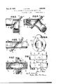
Figures 1 and 2 show diagrammatically the principal elements of a connecter fitting incorporating the present improvements;
Fig. 2 is viewed at right angles to Fig. 1 as indicated by the arrows 22;
Fig. 3 shows the connecter fitting displaced rovide for a 90 degree connection; ig. 4 shows the fitting providing approximately a 30 degree connection;
. Fig. 5 shows the fitting with its parts displaced to provide for a straight through con- 5 Fig.
nection;
Fig. 6 is a detail view taken substantially on lines 6-6 of Fig. 5, but with the clamping rin removed; 7
is a sectional view of the connecter shown in Fig. 5, the section being taken on lines, '(7 of that figure;
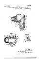
F1 8 is a detailed view of a modification jg v ich a diflerent form of securing means gs is used;-
Fig. 9 is a sectional view of Fig. 8 taken on lines 9-9; and
Fig. 10 is a further detail taken on lines 10-10 of Fig. 9.
Referring to the drawings, the underlying principles of the connecter fitting can be best understood from these diagrammatic views. The connecter elements comprise two abutting parts 10 and 11 which have a transverse cross-section as indicated by the circles 1212. The parts 10 and 11 abut each other on an intersectin plane 13 which is disposed at an angle to t e longitudinal axis of the openings in the parts 10 and 11. Preferably 13 is at an angle of degrees. 14 is .a circle, the diameter of which is that of the length of the plane 13 as shown in Fig. 1.
To provide for swiveling of the part 10 with respect to 11, parts 10 and 11 at the lateral sides adjacent plane 13 are flared as indicated at 15 and 16 in Fig. 2. The extent of such flares is such that the intersecting points of flares 15 and 16 project out from the sides of the elements 10 and 11 to such an extent that these intersecting points just intercept the. circlel i. It will be understood that circle 14 is larger than circle 12. This construction provides for complete swiveling movement of part 10with respect to part 11 and also avoids excessive material at the intersecting point, it being noted that there is no flare shown in Figs. 1 and 5 at all and such flare is only disposed at the two opposite lateral sides as shown in Fig. 2.
Referring now to Fig. 3 parts 10 and 11 are here shown as provided with interiorly threaded female couplings 17 and 18. In order to secure the two elements of the coupling together, flanged portions 19 and 20 are'provided. These flanges are preferably exteriorly threaded to receive a clamping ring 21. It will be understood that by loosening the clamping ring, parts 10 and 11 can be swiveled to any desired angle and thereafter the clamping ring can be tightened up to secure the abutting elements in the desired relative angular relation.
Fig. 4 requires no detailed description, this view shows a section of conduit 19 introduced into the threaded coupling 17 and abutting shoulder 22 as shown.
Fi 5 shows a straight through connection, it being noted that the interior bore of element 11 is in alignment with the bore of element in this figure. This figure corresponds to diagrammatic view Fig. 1.
Fig. 7 shows the connecters in the straight line relation of Fig. 5, but the view is taken at right angles to show the laterally opposite interior flared portions and 16.
Referring now to Figs. 8, 9 and 10 here a different form of securing means is provided for securing element 10 to element 11. According to this embodiment the flange 19 is exteriorly threaded and the periphery of flange 20 is unthreaded as shown in Fig. 8. In lieu of utilizing the clamping ring as heretofore, flange element 21a is rovlded with inwardly turned fingers 22 whic fingers engage back of the flange 20 as shown. To secure the parts together a suitable set screw 23 may be used to clamp against the periphery of flange 20. In Fig. 8 the swivel connecter is shown as receivin an armored cable 24, the cable being clampe by the usual win clamp 25. 26 represents the conducters whic emerge from the armored cable 24 and pass out t rough the element 10. Element 10 in lieu of having a female coupling portion such as 17 is provided with an exteriorly threaded coupling portion 17a.
Preferably the angle of plane 13 with respect to the axis of the two elements is 45 degrees. However, the invention is not limited to such an angle, as other angles can be used as well. However, the most satisfactory arrangement is provided when the angle is degrees since with this relation of the abuttin parts, the angle of swing may be up to 90 egree without excessive size of the flared portions 15 -16.
By providing the flared portions 15 and 16 u on two opposite lateral sides only of the el ments 10 and 11 and omitting such flare on the opposite sides shown in Fig. 1, a construction is provided with continuing inner walls at the top and bottom of the fitting as shown in Fig. 5. This arrangement secures compactness of construction. 1
What I claim is:
1. A connecter fitting for connecting conduits, cables and the like in an electric wiring system, said cqnnectercomprising two elements abutting together in a plane disposed at an angle to the longitudinal axis. of the opening through each fittin said fitting walls being flared out lateral y upon opposite lateral sides only of a transverse crosssection of the fitting to rovide a circular configuration for the interior of the abutting fittings, and means for'securing the two elements of the fitting together.
2. A connecter fitting for providing a universally swiveling connection between conduits, cables and the like in an electrical wiring system, said fitting comprising two parts adapted to abut each other at an angle to the longitudinal axis of the opening through each element, each element being provided with a flared portion upon two opposite lat eral sides only of a transverse cross-section of the fitting to provide for circular mating with the other fitting, each element being further provided adjacent the flared point with an outwardly extendin flange portion, and means cooperating with the flange portions for securing one element to the other at any desired angle between the elements.
In testimony whereof I hereto alfix my signature.
JOHN E. MAIR.
Priority Applications (1)
| Application Number | Priority Date | Filing Date | Title |
|---|---|---|---|
| US465173A US1880098A (en) | 1930-07-01 | 1930-07-01 | Swivel connecter fitting for conduits and the like |
Applications Claiming Priority (1)
| Application Number | Priority Date | Filing Date | Title |
|---|---|---|---|
| US465173A US1880098A (en) | 1930-07-01 | 1930-07-01 | Swivel connecter fitting for conduits and the like |
Publications (1)
| Publication Number | Publication Date |
|---|---|
| US1880098A true US1880098A (en) | 1932-09-27 |
Family
ID=23846762
Family Applications (1)
| Application Number | Title | Priority Date | Filing Date |
|---|---|---|---|
| US465173A Expired - Lifetime US1880098A (en) | 1930-07-01 | 1930-07-01 | Swivel connecter fitting for conduits and the like |
Country Status (1)
| Country | Link |
|---|---|
| US (1) | US1880098A (en) |
Cited By (40)
| Publication number | Priority date | Publication date | Assignee | Title |
|---|---|---|---|---|
| US2453849A (en) * | 1947-03-08 | 1948-11-16 | John L Merriam | Pipe joint |
| US2807479A (en) * | 1955-05-06 | 1957-09-24 | Frank R Hixon | Two way, wall mounted fire hose nozzle |
| US2933891A (en) * | 1953-06-23 | 1960-04-26 | Rolls Royce | Jet pipe arrangements for jet propulsion engines |
| US3737179A (en) * | 1972-01-20 | 1973-06-05 | Hydrotech Services | Submarine connection for misaligned pipes |
| EP0151273A3 (en) * | 1984-02-03 | 1986-07-02 | Anton Hummel Gmbh Metallwarenfabrik | Angular apparatus for threading conductors |
| US4738476A (en) * | 1984-11-19 | 1988-04-19 | Lockheed Corporation | Flexible coupling for fluid ducts |
| US4781405A (en) * | 1984-11-19 | 1988-11-01 | Lockheed Corporation | Flexible coupling for fluid ducts |
| US5064226A (en) * | 1990-05-30 | 1991-11-12 | Hubbell Incorporated | Nonmetallic conduit fitting with transverse biasing abutments |
| US5181885A (en) * | 1990-05-11 | 1993-01-26 | Carraro Spa | Joint structure for connecting a driving steerable wheel hub to an axle, particularly for agricultural tractors |
| US5278749A (en) * | 1990-01-03 | 1994-01-11 | Heiko De Man | Sprinkler flow control method and apparatus |
| US5480195A (en) * | 1993-06-14 | 1996-01-02 | Centrum Merchanizacji Gornictwa "Komag" | High-pressure pipeline |
| US6561549B1 (en) * | 1998-09-10 | 2003-05-13 | Mdc Sarl | Sealing connector with variable geometry |
| US20050002765A1 (en) * | 2003-07-02 | 2005-01-06 | Michael Lambright | Spare tire storage apparatus |
| US6932390B1 (en) * | 2002-10-28 | 2005-08-23 | Arlington Industries, Inc. | Swivel fitting |
| US6957832B1 (en) * | 1999-10-05 | 2005-10-25 | Safe Swivel Patent Co., Pty., Ltd | Elongate member with interconnected rotatable portions |
| US20070246258A1 (en) * | 2006-04-20 | 2007-10-25 | Thomas & Betts International, Inc. | Rotatable liquid-tight conduit connector assembly |
| US20080179880A1 (en) * | 2005-04-18 | 2008-07-31 | Saint-Gobain Pam | Variable-Angle Tubular Connection |
| US20080261428A1 (en) * | 2007-04-20 | 2008-10-23 | Thomas & Betts International, Inc. | Adjustable connector for electrical cable |
| US20090190356A1 (en) * | 2008-01-29 | 2009-07-30 | Thomas & Betts International, Inc. | Lighting fixture having mechanical and electrical interlock and disconnect |
| US20090258509A1 (en) * | 2008-04-15 | 2009-10-15 | Thomas & Betts International, Inc. | Adjustable connector for electrical cable |
| US7690822B2 (en) | 2008-01-29 | 2010-04-06 | Thomas & Betts International, Inc. | Swivel joint for lighting fixture |
| US20100163659A1 (en) * | 2008-12-31 | 2010-07-01 | Progressive International Corporation | Collapsible kitchen tool |
| US20130071264A1 (en) * | 2011-09-19 | 2013-03-21 | Lopin Wang | Portable air pump with a pressure gauge receivable by biasing |
| US8814221B2 (en) * | 2012-06-08 | 2014-08-26 | Swivelpole Patent Pty Ltd. | Facilitating access of pole-mounted items |
| US20150136907A1 (en) * | 2013-11-19 | 2015-05-21 | Airbus Operations Gmbh | Deployable barrier arrangement for selectively blocking a passage in an aircraft cabin |
| US9534626B2 (en) | 2013-06-07 | 2017-01-03 | Swivelpole Patent Pty Ltd | Environmental protection for lowerable pole |
| US20180177174A1 (en) * | 2015-12-15 | 2018-06-28 | Exploding Fish Pty Ltd | Rotatable Fishing Rod Holder |
| US10077705B2 (en) * | 2013-11-19 | 2018-09-18 | Calsonic Kansei Corporation | Flange structure |
| US20190078467A1 (en) * | 2017-09-11 | 2019-03-14 | Ford Global Technologies, Llc | Coupling system for turbocharger and emission control device |
| US10835733B1 (en) | 2011-08-10 | 2020-11-17 | Fisher & Paykel Healthcare Limited | Conduit connector for a patient breathing device |
| USD928948S1 (en) | 2012-08-10 | 2021-08-24 | Fisher & Paykel Healthcare Limited | Connector |
| USD948027S1 (en) | 2019-09-10 | 2022-04-05 | Fisher & Paykel Healthcare Limited | Connector for a breathing conduit |
| US11446462B2 (en) | 2015-03-31 | 2022-09-20 | Fisher & Paykel Healthcare Limited | Apparatus for use in a respiratory support system |
| USD974551S1 (en) | 2020-12-09 | 2023-01-03 | Fisher & Paykel Healthcare Limited | Connector assembly and connector |
| USD995758S1 (en) | 2021-06-11 | 2023-08-15 | Fisher & Paykel Healthcare Limited | Tube assembly and connector |
| USD1006981S1 (en) | 2019-09-06 | 2023-12-05 | Fisher & Paykel Healthcare Limited | Breathing conduit |
| USD1026221S1 (en) | 2020-03-03 | 2024-05-07 | Fisher & Paykel Healthcare Limited | Connector for a respiratory system conduit |
| USD1027165S1 (en) | 2016-06-10 | 2024-05-14 | Fisher & Paykel Healthcare Limited | Connector for a breathing circuit |
| US12115317B2 (en) | 2015-09-04 | 2024-10-15 | Fisher &Paykel Healthcare Limited | Connectors for conduits |
| USD1073919S1 (en) | 2021-05-17 | 2025-05-06 | Fisher & Paykel Healthcare Limited | Respiratory system conduit with connector |
-
1930
- 1930-07-01 US US465173A patent/US1880098A/en not_active Expired - Lifetime
Cited By (66)
| Publication number | Priority date | Publication date | Assignee | Title |
|---|---|---|---|---|
| US2453849A (en) * | 1947-03-08 | 1948-11-16 | John L Merriam | Pipe joint |
| US2933891A (en) * | 1953-06-23 | 1960-04-26 | Rolls Royce | Jet pipe arrangements for jet propulsion engines |
| US2807479A (en) * | 1955-05-06 | 1957-09-24 | Frank R Hixon | Two way, wall mounted fire hose nozzle |
| US3737179A (en) * | 1972-01-20 | 1973-06-05 | Hydrotech Services | Submarine connection for misaligned pipes |
| EP0151273A3 (en) * | 1984-02-03 | 1986-07-02 | Anton Hummel Gmbh Metallwarenfabrik | Angular apparatus for threading conductors |
| US4738476A (en) * | 1984-11-19 | 1988-04-19 | Lockheed Corporation | Flexible coupling for fluid ducts |
| US4781405A (en) * | 1984-11-19 | 1988-11-01 | Lockheed Corporation | Flexible coupling for fluid ducts |
| US5278749A (en) * | 1990-01-03 | 1994-01-11 | Heiko De Man | Sprinkler flow control method and apparatus |
| US5452747A (en) * | 1990-01-03 | 1995-09-26 | De Man; Heiko | Sprinkler flow control apparatus and method |
| US5181885A (en) * | 1990-05-11 | 1993-01-26 | Carraro Spa | Joint structure for connecting a driving steerable wheel hub to an axle, particularly for agricultural tractors |
| US5064226A (en) * | 1990-05-30 | 1991-11-12 | Hubbell Incorporated | Nonmetallic conduit fitting with transverse biasing abutments |
| US5480195A (en) * | 1993-06-14 | 1996-01-02 | Centrum Merchanizacji Gornictwa "Komag" | High-pressure pipeline |
| US6561549B1 (en) * | 1998-09-10 | 2003-05-13 | Mdc Sarl | Sealing connector with variable geometry |
| US6957832B1 (en) * | 1999-10-05 | 2005-10-25 | Safe Swivel Patent Co., Pty., Ltd | Elongate member with interconnected rotatable portions |
| US6932390B1 (en) * | 2002-10-28 | 2005-08-23 | Arlington Industries, Inc. | Swivel fitting |
| US20050002765A1 (en) * | 2003-07-02 | 2005-01-06 | Michael Lambright | Spare tire storage apparatus |
| US9796433B2 (en) * | 2003-07-02 | 2017-10-24 | Michael Lambright | Spare tire storage apparatus |
| US20080179880A1 (en) * | 2005-04-18 | 2008-07-31 | Saint-Gobain Pam | Variable-Angle Tubular Connection |
| US7699355B2 (en) * | 2005-04-18 | 2010-04-20 | Saint-Gobain Pam | Variable-angle tubular connection |
| US7394021B2 (en) | 2006-04-20 | 2008-07-01 | Magno Jr Joey D | Rotatable liquid-tight conduit connector assembly |
| US20070246258A1 (en) * | 2006-04-20 | 2007-10-25 | Thomas & Betts International, Inc. | Rotatable liquid-tight conduit connector assembly |
| US20080261428A1 (en) * | 2007-04-20 | 2008-10-23 | Thomas & Betts International, Inc. | Adjustable connector for electrical cable |
| US7909636B2 (en) | 2007-04-20 | 2011-03-22 | Thomas & Betts International, Inc. | Adjustable connector for electrical cable |
| US20090190356A1 (en) * | 2008-01-29 | 2009-07-30 | Thomas & Betts International, Inc. | Lighting fixture having mechanical and electrical interlock and disconnect |
| US7690822B2 (en) | 2008-01-29 | 2010-04-06 | Thomas & Betts International, Inc. | Swivel joint for lighting fixture |
| US7832910B2 (en) | 2008-01-29 | 2010-11-16 | Thomas & Betts International, Inc. | Lighting fixture having mechanical and electrical interlock and disconnect |
| US20090258509A1 (en) * | 2008-04-15 | 2009-10-15 | Thomas & Betts International, Inc. | Adjustable connector for electrical cable |
| US7905746B2 (en) | 2008-04-15 | 2011-03-15 | Thomas & Betts International, Inc. | Adjustable connector for electrical cable |
| US20100163659A1 (en) * | 2008-12-31 | 2010-07-01 | Progressive International Corporation | Collapsible kitchen tool |
| US8083168B2 (en) * | 2008-12-31 | 2011-12-27 | Progressive International Corporation | Collapsible kitchen tool |
| US12544549B2 (en) | 2011-08-10 | 2026-02-10 | Fisher & Paykel Healthcare Limited | Conduit connector for a patient breathing device |
| US10835733B1 (en) | 2011-08-10 | 2020-11-17 | Fisher & Paykel Healthcare Limited | Conduit connector for a patient breathing device |
| US11690995B2 (en) | 2011-08-10 | 2023-07-04 | Fisher & Paykel Healthcare Limited | Conduit connector for a patient breathing device |
| US8932027B2 (en) * | 2011-09-19 | 2015-01-13 | Beto Engineering and Marketing Co., Ltd. | Portable air pump with a pressure gauge receivable by biasing |
| US20130071264A1 (en) * | 2011-09-19 | 2013-03-21 | Lopin Wang | Portable air pump with a pressure gauge receivable by biasing |
| US8814221B2 (en) * | 2012-06-08 | 2014-08-26 | Swivelpole Patent Pty Ltd. | Facilitating access of pole-mounted items |
| USD1050426S1 (en) | 2012-08-10 | 2024-11-05 | Fisher & Paykel Healthcare Limited | Connector |
| USD928949S1 (en) | 2012-08-10 | 2021-08-24 | Fisher & Paykel Healthcare Limited | Connector |
| USD928948S1 (en) | 2012-08-10 | 2021-08-24 | Fisher & Paykel Healthcare Limited | Connector |
| US9534626B2 (en) | 2013-06-07 | 2017-01-03 | Swivelpole Patent Pty Ltd | Environmental protection for lowerable pole |
| US20150136907A1 (en) * | 2013-11-19 | 2015-05-21 | Airbus Operations Gmbh | Deployable barrier arrangement for selectively blocking a passage in an aircraft cabin |
| US10077705B2 (en) * | 2013-11-19 | 2018-09-18 | Calsonic Kansei Corporation | Flange structure |
| US12201776B2 (en) | 2015-03-31 | 2025-01-21 | Fisher & Paykel Healthcare Limited | Apparatus for use in a respiratory support system |
| US11446462B2 (en) | 2015-03-31 | 2022-09-20 | Fisher & Paykel Healthcare Limited | Apparatus for use in a respiratory support system |
| US12115317B2 (en) | 2015-09-04 | 2024-10-15 | Fisher &Paykel Healthcare Limited | Connectors for conduits |
| JP2018537101A (en) * | 2015-12-15 | 2018-12-20 | エクスプローディング フィッシュ ピーティーワイ リミテッドExploding Fish Pty Ltd | Rotating fishing rod holding device |
| US11172665B2 (en) * | 2015-12-15 | 2021-11-16 | Evolution International Holdings Pty Ltd | Rotatable fishing rod holder |
| AU2016374491B2 (en) * | 2015-12-15 | 2021-04-01 | Evolution International Holdings Pty Ltd | Rotatable fishing rod holder |
| US20180177174A1 (en) * | 2015-12-15 | 2018-06-28 | Exploding Fish Pty Ltd | Rotatable Fishing Rod Holder |
| CN108471735A (en) * | 2015-12-15 | 2018-08-31 | 爆鱼股份有限公司 | Rotatable fishing rod fixator |
| USD1027165S1 (en) | 2016-06-10 | 2024-05-14 | Fisher & Paykel Healthcare Limited | Connector for a breathing circuit |
| USD1028213S1 (en) | 2016-06-10 | 2024-05-21 | Fisher & Paykel Healthcare Limited | Connector for a breathing circuit |
| US20190078467A1 (en) * | 2017-09-11 | 2019-03-14 | Ford Global Technologies, Llc | Coupling system for turbocharger and emission control device |
| US10570778B2 (en) * | 2017-09-11 | 2020-02-25 | Ford Global Technologies, Llc | Coupling system for turbocharger and emission control device |
| USD1006981S1 (en) | 2019-09-06 | 2023-12-05 | Fisher & Paykel Healthcare Limited | Breathing conduit |
| USD1102587S1 (en) | 2019-09-06 | 2025-11-18 | Fisher & Paykel Healthcare Limited | Breathing conduit |
| USD1037433S1 (en) | 2019-09-10 | 2024-07-30 | Fisher & Paykel Healthcare Limited | Connector for a breathing conduit |
| USD983353S1 (en) | 2019-09-10 | 2023-04-11 | Fisher & Paykel Healthcare Limited | Connector for a breathing conduit |
| USD1074989S1 (en) | 2019-09-10 | 2025-05-13 | Fisher & Paykel Healthcare Limited | Connector for a breathing conduit |
| USD948027S1 (en) | 2019-09-10 | 2022-04-05 | Fisher & Paykel Healthcare Limited | Connector for a breathing conduit |
| USD1026221S1 (en) | 2020-03-03 | 2024-05-07 | Fisher & Paykel Healthcare Limited | Connector for a respiratory system conduit |
| USD1054555S1 (en) | 2020-12-09 | 2024-12-17 | Fisher & Paykel Healthcare Limited | Conduit connector |
| USD974551S1 (en) | 2020-12-09 | 2023-01-03 | Fisher & Paykel Healthcare Limited | Connector assembly and connector |
| USD1073919S1 (en) | 2021-05-17 | 2025-05-06 | Fisher & Paykel Healthcare Limited | Respiratory system conduit with connector |
| USD1039134S1 (en) | 2021-06-11 | 2024-08-13 | Fisher & Paykel Healthcare Limited | Tube assembly and connector |
| USD995758S1 (en) | 2021-06-11 | 2023-08-15 | Fisher & Paykel Healthcare Limited | Tube assembly and connector |
Similar Documents
| Publication | Publication Date | Title |
|---|---|---|
| US1880098A (en) | Swivel connecter fitting for conduits and the like | |
| US3967838A (en) | Banjo type pipe unions | |
| US2100796A (en) | Pipe coupler | |
| GB1404515A (en) | Coaxial connector | |
| US3384393A (en) | Conduit connector for junction boxes | |
| US2260136A (en) | Electrical grounding connector | |
| US1941905A (en) | Grounding device for electrical wiring systems | |
| US2335040A (en) | Coupling means for tubular electrical conductor sections | |
| US4145566A (en) | Housing for electrical devices | |
| US2298516A (en) | Joint for concentric conductors | |
| US2942898A (en) | Connector | |
| US1880081A (en) | Ground clamp for outlet and switch boxes | |
| US1152005A (en) | Coupling-connector for submarine cables. | |
| US3662087A (en) | Universal conduit connector | |
| US2318237A (en) | Antenna feed system | |
| US3757280A (en) | Connecting structure for helically corrugated tubing | |
| US1921056A (en) | Duct fitting | |
| US1809064A (en) | Threadless connecter | |
| US1295304A (en) | Multiple-wire connector. | |
| US1966132A (en) | Grounding device | |
| GB332729A (en) | Improvements in electric cable connectors or joints | |
| US3284109A (en) | Tapping saddle for polyethylene cable | |
| US1899309A (en) | Grounding fitting | |
| US1864292A (en) | Grounding clamp | |
| US1456792A (en) | Conduit-outlet box |