EP3789972B1 - System und verfahren zum sammeln von fluglastdaten - Google Patents
System und verfahren zum sammeln von fluglastdaten Download PDFInfo
- Publication number
- EP3789972B1 EP3789972B1 EP19212397.4A EP19212397A EP3789972B1 EP 3789972 B1 EP3789972 B1 EP 3789972B1 EP 19212397 A EP19212397 A EP 19212397A EP 3789972 B1 EP3789972 B1 EP 3789972B1
- Authority
- EP
- European Patent Office
- Prior art keywords
- acquisition unit
- data acquisition
- translating sleeve
- sensor
- blocker
- Prior art date
- Legal status (The legal status is an assumption and is not a legal conclusion. Google has not performed a legal analysis and makes no representation as to the accuracy of the status listed.)
- Active
Links
Images




Classifications
-
- G—PHYSICS
- G01—MEASURING; TESTING
- G01M—TESTING STATIC OR DYNAMIC BALANCE OF MACHINES OR STRUCTURES; TESTING OF STRUCTURES OR APPARATUS, NOT OTHERWISE PROVIDED FOR
- G01M15/00—Testing of engines
- G01M15/14—Testing gas-turbine engines or jet-propulsion engines
-
- G—PHYSICS
- G07—CHECKING-DEVICES
- G07C—TIME OR ATTENDANCE REGISTERS; REGISTERING OR INDICATING THE WORKING OF MACHINES; GENERATING RANDOM NUMBERS; VOTING OR LOTTERY APPARATUS; ARRANGEMENTS, SYSTEMS OR APPARATUS FOR CHECKING NOT PROVIDED FOR ELSEWHERE
- G07C5/00—Registering or indicating the working of vehicles
- G07C5/08—Registering or indicating performance data other than driving, working, idle, or waiting time, with or without registering driving, working, idle or waiting time
- G07C5/0841—Registering performance data
-
- B—PERFORMING OPERATIONS; TRANSPORTING
- B64—AIRCRAFT; AVIATION; COSMONAUTICS
- B64D—EQUIPMENT FOR FITTING IN OR TO AIRCRAFT; FLIGHT SUITS; PARACHUTES; ARRANGEMENT OR MOUNTING OF POWER PLANTS OR PROPULSION TRANSMISSIONS IN AIRCRAFT
- B64D45/00—Aircraft indicators or protectors not otherwise provided for
-
- B—PERFORMING OPERATIONS; TRANSPORTING
- B64—AIRCRAFT; AVIATION; COSMONAUTICS
- B64F—GROUND OR AIRCRAFT-CARRIER-DECK INSTALLATIONS SPECIALLY ADAPTED FOR USE IN CONNECTION WITH AIRCRAFT; DESIGNING, MANUFACTURING, ASSEMBLING, CLEANING, MAINTAINING OR REPAIRING AIRCRAFT, NOT OTHERWISE PROVIDED FOR; HANDLING, TRANSPORTING, TESTING OR INSPECTING AIRCRAFT COMPONENTS, NOT OTHERWISE PROVIDED FOR
- B64F5/00—Designing, manufacturing, assembling, cleaning, maintaining or repairing aircraft, not otherwise provided for; Handling, transporting, testing or inspecting aircraft components, not otherwise provided for
- B64F5/60—Testing or inspecting aircraft components or systems
-
- F—MECHANICAL ENGINEERING; LIGHTING; HEATING; WEAPONS; BLASTING
- F01—MACHINES OR ENGINES IN GENERAL; ENGINE PLANTS IN GENERAL; STEAM ENGINES
- F01D—NON-POSITIVE DISPLACEMENT MACHINES OR ENGINES, e.g. STEAM TURBINES
- F01D17/00—Regulating or controlling by varying flow
- F01D17/02—Arrangement of sensing elements
-
- F—MECHANICAL ENGINEERING; LIGHTING; HEATING; WEAPONS; BLASTING
- F02—COMBUSTION ENGINES; HOT-GAS OR COMBUSTION-PRODUCT ENGINE PLANTS
- F02K—JET-PROPULSION PLANTS
- F02K1/00—Plants characterised by the form or arrangement of the jet pipe or nozzle; Jet pipes or nozzles peculiar thereto
- F02K1/54—Nozzles having means for reversing jet thrust
- F02K1/64—Reversing fan flow
- F02K1/70—Reversing fan flow using thrust reverser flaps or doors mounted on the fan housing
-
- F—MECHANICAL ENGINEERING; LIGHTING; HEATING; WEAPONS; BLASTING
- F02—COMBUSTION ENGINES; HOT-GAS OR COMBUSTION-PRODUCT ENGINE PLANTS
- F02K—JET-PROPULSION PLANTS
- F02K1/00—Plants characterised by the form or arrangement of the jet pipe or nozzle; Jet pipes or nozzles peculiar thereto
- F02K1/54—Nozzles having means for reversing jet thrust
- F02K1/64—Reversing fan flow
- F02K1/70—Reversing fan flow using thrust reverser flaps or doors mounted on the fan housing
- F02K1/72—Reversing fan flow using thrust reverser flaps or doors mounted on the fan housing the aft end of the fan housing being movable to uncover openings in the fan housing for the reversed flow
-
- G—PHYSICS
- G01—MEASURING; TESTING
- G01H—MEASUREMENT OF MECHANICAL VIBRATIONS OR ULTRASONIC, SONIC OR INFRASONIC WAVES
- G01H1/00—Measuring characteristics of vibrations in solids by using direct conduction to the detector
- G01H1/003—Measuring characteristics of vibrations in solids by using direct conduction to the detector of rotating machines
- G01H1/006—Measuring characteristics of vibrations in solids by using direct conduction to the detector of rotating machines of the rotor of turbo machines
-
- G—PHYSICS
- G01—MEASURING; TESTING
- G01M—TESTING STATIC OR DYNAMIC BALANCE OF MACHINES OR STRUCTURES; TESTING OF STRUCTURES OR APPARATUS, NOT OTHERWISE PROVIDED FOR
- G01M15/00—Testing of engines
- G01M15/04—Testing internal-combustion engines
- G01M15/042—Testing internal-combustion engines by monitoring a single specific parameter not covered by groups G01M15/06 - G01M15/12
- G01M15/048—Testing internal-combustion engines by monitoring a single specific parameter not covered by groups G01M15/06 - G01M15/12 by monitoring temperature
Definitions
- This disclosure relates generally to gas turbine engines, and more particularly to systems and methods for gathering gas turbine engine flight load data.
- issues e.g., component mechanical issues
- Those issues may be solved via testing or analysis of the affected components.
- the issue cannot be solved without accurate in-flight load data. Without a flight test program, getting the load data can be difficult.
- test flight programs may involve installation of test equipment such as large controllers or data acquisition systems which may require substantial changes to the architecture of the gas turbine engine.
- installation of the test equipment may require the fabrication and installation of new mounting points and mounting hardware as well as complicated wiring assemblies between the test equipment and sensors disposed in the gas turbine engine.
- the installed test equipment may substantially affect the aerodynamic qualities of the nacelle of the gas turbine engine.
- an exemplary gas turbine engine 10 is illustrated mounted to, for example, a wing 1000W of an aircraft 1000.
- the gas turbine engine 10 includes a nacelle 12 defining a housing of the gas turbine engine 10 about an axial centerline 14.
- the nacelle 12 supports and generally surrounds an engine core which generally includes a fan section 16, a compressor section 18, a combustor section 20, and a turbine section 22.
- the fan section 16 drives air along a bypass flowpath 24 while the compressor section 18 drives air along a core flowpath 26 for compression and communication into the combustor section 20 and then expansion through the turbine section 22.
- the nacelle 12 may generally include an intake cowl 28 disposed forward of the fan section 16, a fan cowl 30 that circumferentially surrounds and shields the fan section 16, and a thrust reverser 32 that may circumferentially surround one or more of the compressor section 18, the combustor section 20, and the turbine section 22. At least a portion of the thrust reverser 32 may be configured to move (e.g., axially) relative to the intake cowl 28 and the fan cowl 30 of the nacelle 12.
- the thrust reverser 32 may be, for example, a cascade-type thrust reverser.
- the thrust reverser 32 may include a plurality of cascade elements 34 and a translating sleeve 36 configured to mount to and axially translate along a track 38.
- the thrust reverser 32 may further include a portion of an inner barrel 44 of the nacelle 12.
- the translating sleeve 36 may be formed from one or more translating sleeve portions, for example, a first translating sleeve portion 40 and a second translating sleeve portion 42 as shown in FIG. 3 .
- the translating sleeve portions 40, 42 may be generally semi-cylindrical in shape and may form an aft portion of the nacelle 12 configured to move relative to the remainder of the nacelle 12 by axially translating along the track 38.
- the translating sleeve 36 may be radially spaced from the engine core of the gas turbine engine 10 thereby defining a portion of the bypass flowpath 24 between an interior surface 46 of the translating sleeve 36 and the engine core.
- the thrust reverser 32 may include one or more actuating units (not shown) configured to effect translation of the translating sleeve 36 by moving the translating sleeve 36 axially along the track 38.
- the translating sleeve 36 of the thrust reverser 32 is configured to translate axially between a "deployed" position and a "stowed” position. With the translating sleeve 36 in the stowed position, the thrust reverser 32 is configured so as to not substantially impede bypass airflow transiting along the bypass flowpath 24. Accordingly, with the translating sleeve 36 in the stowed position, the bypass airflow may provide thrust for forward propulsion of the aircraft 1000. With the translating sleeve 36 in the deployed position, the thrust reverser 32 may be configured to block all or a substantial portion of the bypass airflow transiting along the bypass flowpath 24.
- the thrust reverser 32 may be configured to redirect the bypass airflow transiting along the bypass flowpath 24 in a direction to counter forward propulsion of the aircraft 1000, such as through the plurality of cascade elements 34.
- the thrust reverser 32 may include a plurality of blocker doors 48 rotatably mounted to the translating sleeve 36 by, for example, one or more hinges 50 (e.g., the plurality of blocker doors 48 may be hingedly attached to the translating sleeve 36 by the one or more hinges 50).
- the plurality of blocker doors 48 may be disposed circumferentially about a radially inner portion of the translating sleeve 36.
- Each blocker door of the plurality of blocker doors 48 may be connected, at a connection point 52, to a respective blocker door link of a plurality of blocker door links 54.
- the plurality of blocker door links 54 may be mounted to and extend from a fixed portion of the nacelle 12 such as, for example, the inner barrel 44. Accordingly, as the translating sleeve 36 translates in a forward to aft direction from the stowed position to the deployed position, the plurality of blocker door links 54 may cause the respective plurality of blocker doors 48 to rotate in a first direction about the one or more hinges 50 such that the plurality of blocker doors 48 obstruct all or a substantial portion of the bypass flowpath 24 (e.g., a "deployed" position of the plurality of blocker doors 48).
- the plurality of blocker door links 54 may cause the respective plurality of blocker doors 48 to rotate in a second direction, opposite the first direction, about the one or more hinges 50 such that the plurality of blocker doors 48 do not substantially obstruct the flow of bypass air along the bypass flowpath 24 (e.g., a "stowed" position of the plurality of blocker doors 48).
- the plurality of blocker doors 48 may include an inner radial side 56 which may form a portion of the interior surface 46 of the translating sleeve 36 when the translating sleeve 36 is in the stowed position.
- the plurality of blocker doors 48 may also include an outer radial side 58, opposite the inner radial side 56, which may be mounted to the translating sleeve 36 with the one or more hinges 50.
- the plurality of blocker doors 48 may alternatively be retained within the translating sleeve 36 (e.g., within an internal cavity or recess of the translating sleeve 36) when in the stowed position.
- the inner radial side 56 the plurality of blocker doors 48 may not form a portion of the interior surface 46 of the translating sleeve 36 when the translating sleeve 36 and the plurality of blocker doors 48 are in their respective stowed positions (e.g., the inner radial side 56 of the plurality of blocker doors 48 may be radially spaced from the interior surface 46 of the translating sleeve 36).
- the plurality of blocker doors 48 may alternatively be rotatably mounted to the inner barrel 44 by the one or more hinges 50 as opposed to being rotatably mounted to the translating sleeve 36.
- the plurality of blocker doors 48 may be operated by the plurality of blocker door links 54 alternatively mounted, for example, to the translating sleeve 36 or by any other suitable mechanical means.
- the plurality of blocker doors 48 may form a portion of the exterior surface of the inner barrel 44 with the plurality of blocker doors 48 in the stowed position, thereby further defining the bypass flowpath 24 between the translating sleeve 36 and the inner barrel 44.
- the thrust reverser 32 may additionally include a plurality of blocker door islands 60.
- Each blocker door island of the plurality of blocker door islands 60 may be disposed between each pair of circumferentially adjacent blocker doors of the plurality of blocker doors 48.
- the plurality of blocker door islands 60 may be fixedly mounted to the translating sleeve 36 alternatingly between the plurality of blocker doors 48 in order to provide a substantially continuous interior surface 46 of the translating sleeve 32 in the stowed position so as to reduce or eliminate detrimental bypass airflow characteristics of the plurality of blocker doors 48.
- the plurality of blocker door islands 60 may include an inner radial side 62 which may form a portion of the interior surface 46 of the translating sleeve 36.
- the inner radial sides 56, 62 plurality of blocker doors 48 and the plurality of blocker door islands 60 may form a substantially continuous surface defining a portion of the interior surface 46 of the translating sleeve 36.
- the plurality of blocker door islands 60 may also include an outer radial side 64, opposite the inner radial side 62, which may be mounted to the translating sleeve 36 with one or more support brackets 66.
- the translating sleeve 36 may include one or more mounting points 80, such as one or more fastener holes, through which the one or more support brackets 66 may be mounted to the translating sleeve 36, for example, by one or more fasteners.
- the plurality of blocker door islands 60 may be fixedly mounted to the inner barrel 44.
- the plurality of blocker door islands 60 in this configuration may be alternatingly disposed between the plurality of blocker doors 48 in order to form a portion of a substantially continuous exterior surface of the inner barrel 44.
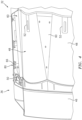
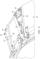
- At least one blocker door island of the plurality of blocker door islands 60 may be a data acquisition unit 68 in communication with at least one sensor in communication with the translating sleeve 36.
- the data acquisition unit 68 may be configured to gather flight load data during operation of the gas turbine engine 10.
- the data acquisition unit 68 may have a size, shape, and mounting configuration that is substantially identical to the other blocker door islands of the plurality of blocker door islands 60 such that a previously-installed, "conventional" (i.e., a non-data acquisition unit 68 blocker door island) can be replaced with the data acquisition unit 68 to incorporate monitoring of flight loads with minimal effect on the structural and/or aerodynamic capabilities of the nacelle 12.
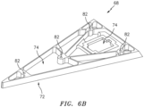
- the data acquisition unit 68 may include a data acquisition unit frame 72 which may have a size and shape which is substantially identical to the conventional blocker door islands of the plurality of blocker door islands 60.
- the data acquisition unit frame 72 may be made from a same material as the conventional blocker door islands of the plurality of blocker door islands 60.
- the data acquisition unit frame 72 may be made from a different material than the conventional blocker door islands of the plurality of blocker door islands 60.
- the data acquisition unit frame 72 may include one or more recesses 74 within which electronic components of the data acquisition unit 68 may be disposed.
- the data acquisition unit frame 72 may include one or more attachment apertures 82 configured to receive and retain the one or more support brackets 66 for mounting the data acquisition unit 68 to the translating sleeve 36 (e.g., by threaded engagement between the one or more attachment apertures 82 and the one or more support brackets 66).
- the data acquisition unit 68 may include an edge computing node (ECN) unit disposed in one of the recesses 74.
- the ECN unit may be in communication (e.g., signal communication) with the at least one sensor.
- the ECN unit may include any type of computing device, computational circuit, or any type of process or processing circuit capable of executing a series of instructions that are stored in memory, for example, in a memory device of the ECN unit.
- the ECN unit may include multiple processors and/or multicore CPUs and may include any type of processor, such as a microprocessor, digital signal processor, co-processors, a micro-controller, a central processing unit, a field programmable gate array, a programmable logic device, a state machine, logic circuitry, analog circuitry, digital circuitry, etc., and any combination thereof.
- the instructions stored in memory may represent one or more algorithms for controlling the aspects of the data acquisition unit 68 and the stored instructions are not limited to any particular form (e.g., program files, system data, buffers, drivers, utilities, system programs, etc.) provided they can be executed by the ECN unit processor.
- the memory device of the ECN unit may be a non-transitory computer readable storage medium configured to store instructions that when executed by one or more processors, cause the one or more processors to perform or cause the performance of certain functions.
- the memory device may be a single memory device or a plurality of memory devices.
- the memory device may include a storage area network, network attached storage, as well a disk drive, a read-only memory, random access memory, volatile memory, non-volatile memory, static memory, dynamic memory, flash memory, cache memory, and/or any device that stores digital information.
- One skilled in the art will appreciate, based on a review of this disclosure, that the implementation of the ECN unit 72 may be achieved via the use of hardware, software, firmware, or any combination thereof.
- the ECN unit 72 may additionally be in signal communication with one or more input devices (e.g., a keyboard, a touch screen, etc.) and output devices (a monitor, sensor readouts, data ports, etc.) that enable an operator to input instructions, receive data, etc.
- input devices e.g., a keyboard, a touch screen, etc.
- output devices a monitor, sensor readouts, data ports, etc.
- the data acquisition unit 68 may include a battery 78 disposed in one of the recesses 74.
- the battery 78 may provide power to electronic components of the data acquisition unit 68 such as, for example, the ECN unit such that the data acquisition unit 68 does not require a connection to an alternative power source outside the data acquisition unit 68.
- the battery 78 may provide power to the ECN unit by, for example, a cable 84.
- the data acquisition unit frame 72 of the data acquisition unit 68 may include one or more attachment bosses 82 configured to receive and retain the one or more respective support brackets 66 for mounting the data acquisition unit 68 to the translating sleeve 36.
- the data acquisition unit 68 may be configured to store the flight load data from the at least one sensor in memory for subsequent analysis. In various embodiments, the data acquisition unit 68 may alternatively or additionally transmit the flight load data from the at least one sensor to one or more external devices (e.g., devices outside the data acquisition unit 68) for storage in memory and/or real-time analysis of the flight load data.
- the data acquisition unit 68 may be in wired or wireless communication with the at least one sensor and the one or more external devices. As shown in FIGS. 3 and 6A , the ECN unit of the data acquisition unit 68 is in communication with the at least one sensor via a wire 86.
- the at least one sensor may include one or more sensors configured to measure various parameters including for example, but not limited to, pressure, temperature, acceleration, vibration, altitude, and/or attitude.
- the at least one sensor may be mounted to the translating sleeve 36 at any suitable position for gathering flight load data.
- the at least one sensor may be mounted to the interior surface 46 of the translating sleeve 36.
- the data acquisition unit 68 may use existing blocker door island mounting points 80 for attachment to the translating sleeve 36 allowing the data acquisition unit 68 to be installed and removed from the translating sleeve 36 during brief flight tests.
- Disposition of the data acquisition unit 68 and the at least one sensor in the translating sleeve 36 may simplify installation as the data acquisition unit 68 and the at least one sensor may translate axially together with the translating sleeve 36 (e.g., the data acquisition unit 68 and the at least one sensor may be fixed relative to one another regardless of the translating sleeve 36 position), thereby simplifying wiring requirements between the data acquisition unit 68 and the at least one sensor.
- both the data acquisition unit 68 and the at least one sensor may be mounted to the inner barrel 44.
- a method 700 for gathering flight load data for a gas turbine engine such as the gas turbine engine 10, is provided.
- the plurality of blocker doors 48 rotatably mounted to the translating sleeve 36 and a plurality of blocker door islands 60 are provided.
- Each blocker door island of the plurality of blocker door islands 60 is disposed between circumferentially adjacent blocker doors of the plurality of blocker doors 48 and mounted to the at least one mounting point 80 of the translating sleeve 36.
- At least one blocker door island of the plurality of blocker door islands 60 is the data acquisition unit 68.
- Block 702 may further include replacing at least one blocker door island (e.g., a "conventional" blocker door island) of the plurality of blocker door islands 60 with the data acquisition unit 68 and mounting the data acquisition unit 68 to the at least one mounting point 80 of the translating sleeve 36. Accordingly, the data acquisition unit 68 may be mounted to the translating sleeve 36 at the existing one or more mounting points 80 to which the replaced at least one blocker door island of the plurality of blocker door islands 60 was previously mounted.
- at least one blocker door island e.g., a "conventional" blocker door island
- flight load data from the at least one sensor is gathered.
- the ECN unit of the data acquisition unit 68 may receive the flight load data from the at least one sensor.
- the flight load data received from the at least one sensor is stored with the data acquisition unit 68.
- the ECN unit of the data acquisition unit 68 may store the flight load data in memory and/or may transmit the flight load data to one or more external devices for storage.
- the data acquisition unit 68 may be removed from the translating sleeve 36.
- the flight load data stored by the data acquisition unit 68 may be read. It should be noted, however, that the data acquisition unit 68 need not be removed from the translating sleeve 36 prior to reading the flight load data from the data acquisition unit 68.
- the data acquisition unit 68 is described with respect to the plurality of blocker door islands 60, it should be understood that the present disclosure not limited to the use of a blocker door island as the data acquisition unit 68.
- the data acquisition unit 68 may have a suitable size, shape, and mounting configuration such that the data acquisition unit 68 can be substituted for one or more other components of the gas turbine engine 10.
Landscapes
- Engineering & Computer Science (AREA)
- Physics & Mathematics (AREA)
- General Physics & Mathematics (AREA)
- Chemical & Material Sciences (AREA)
- Combustion & Propulsion (AREA)
- Mechanical Engineering (AREA)
- General Engineering & Computer Science (AREA)
- Aviation & Aerospace Engineering (AREA)
- Manufacturing & Machinery (AREA)
- Transportation (AREA)
- Arrangements For Transmission Of Measured Signals (AREA)
- Rolling Contact Bearings (AREA)
Claims (14)
- Verfahren zum Sammeln von Fluglastdaten für ein Gasturbinentriebwerk (10), wobei das Verfahren umfasst:Bereitstellen einer Vielzahl von Sperrtüren (48), die drehbar an einer Verschiebungshülse (36) montiert sind, und einer Vielzahl von Sperrtürinseln (60), wobei jede Sperrtürinsel (60) zwischen in Umfangsrichtung benachbarten Sperrtüren (48) der Vielzahl von Sperrtüren (48) angeordnet ist und an mindestens einem Montagepunkt (80) der Verschiebungshülse (36) montiert ist, dadurch gekennzeichnet, dass eine Sperrtürinsel (60) der Vielzahl von Sperrtürinseln (60) eine Datenerfassungseinheit (68) ist; undVerbinden der Datenerfassungseinheit (68) mit mindestens einem Sensor in Verbindung mit der Verschiebungshülse (36), und wobei das Verfahren ferner das Sammeln von Fluglastdaten von dem mindestens einen Sensor mit der Datenerfassungseinheit umfasst.
- Verfahren nach Anspruch 1, wobei der Schritt des Bereitstellens der Vielzahl von Sperrtüren (48), die drehbar an der Verschiebungshülse (36) montiert sind, und der Vielzahl von Sperrtürinseln (60) Ersetzen einer ersten Sperrtürinsel (60) der Vielzahl von Sperrtürinseln (60) durch die Datenerfassungseinheit (68) und Montieren der Datenerfassungseinheit (68) an dem mindestens einen Montagepunkt (80) der Verschiebungshülse (36) beinhaltet.
- Verfahren nach Anspruch 1 oder 2, wobei das Gasturbinentriebwerk (10) eine Gondel (12) beinhaltet, die die Verschiebungshülse (36) und einen Gondelabschnitt, der axial neben der Verschiebungshülse (36) liegt, umfasst, wobei die Verschiebungshülse (36) und der Gondelabschnitt um eine axiale Mittellinie (14) des Gasturbinentriebwerks (10) herum angeordnet sind.
- Verfahren nach Anspruch 3, wobei die Verschiebungshülse (36) konfiguriert ist, um sich relativ zu dem Gondelabschnitt axial zu verschieben und der Gondelabschnitt relativ zu dem Gasturbinentriebwerk (10) axial fixiert ist.
- Verfahren nach Anspruch 4, ferner umfassend Speichern der Fluglastdaten mit der Datenerfassungseinheit (68).
- Verfahren nach Anspruch 5, ferner umfassend:Entfernen der Datenerfassungseinheit (68) von der Verschiebungshülse (36) nach dem Speichern der Fluglastdaten; undLesen der in der Datenerfassungseinheit (68) gespeicherten Fluglastdaten.
- Verfahren nach einem der vorhergehenden Ansprüche, wobei der mindestens eine Sensor einen oder mehrere von einem Temperatursensor oder einem Drucksensor beinhaltet.
- Verfahren nach einem der vorhergehenden Ansprüche, wobei die Datenerfassungseinheit (68) über eine Leitung (86) mit dem mindestens einen Sensor in Verbindung steht.
- Verfahren nach Anspruch 8,
wobei die Datenerfassungseinheit (68) und der mindestens eine Sensor konfiguriert sind, um sich axial mit der Verschiebungshülse (36) zu verschieben. - System zum Sammeln von Fluglastdaten eines Gasturbinentriebwerks, wobei das System umfasst:einen Schubumkehrer (32), der eine Verschiebungshülse (36) und eine innere Trommel (44) umfasst;eine Vielzahl von Sperrtüren (48), die gelenkig an dem Schubumkehrer (32) angebracht sind;eine Vielzahl von Sperrtürinseln (60), wobei jede Sperrtürinsel (60) zwischen in Umfangsrichtung benachbarten Sperrtüren (48) der Vielzahl von Sperrtüren (48) angeordnet und an mindestens einem Montagepunkt (80) des Schubumkehrers (32) montiert ist; dadurch gekennzeichnet, dass das System ferner umfasst:mindestens einen Sensor in Verbindung mit dem Schubumkehrer (32),wobei eine Sperrtürinsel (60) der Vielzahl von Sperrtürinseln (60) eine Datenerfassungseinheit (68) ist und die Datenerfassungseinheit (68) mit dem mindestens einen Sensor verbunden ist,wobei die Datenerfassungseinheit (68) konfiguriert ist, um Fluglastdaten von dem mindestens einen Sensor zu sammeln,wobei die Datenerfassungseinheit (68) optional über eine Leitung (86) mit dem mindestens einen Sensor in Verbindung steht.
- Gasturbinentriebwerk (10), umfassend:das System nach Anspruch 10;einen Triebwerkskern, der eine axiale Mittellinie (14) aufweit; undeine Gondel (12), die den Triebwerkskern umgibt, wobei die Gondel (12) einen axial befestigten Gondelabschnitt umfasst, der axial neben dem Schubumkehrer (32) liegt.
- Gasturbinentriebwerk (10) nach Anspruch 11,
wobei die Datenerfassungseinheit (68) eine äußere radiale Seite (64), die an der Verschiebungshülse (36) montiert ist, und eine innere radiale Seite (62) gegenüber der äußeren radialen Seite (64) aufweist und wobei die innere radiale Seite (62) einen Abschnitt eines Bypass-Strömungswegs (24) des Gasturbinentriebwerks (10) definiert. - System oder Gasturbinentriebwerk (10) nach Anspruch 10, 11 oder 12,
wobei die Datenerfassungseinheit (68) und der mindestens eine Sensor konfiguriert sind, um sich axial mit der Verschiebungshülse (36) zu verschieben. - System oder Gasturbinentriebwerk (10) nach einem der Ansprüche 10 bis 13,
wobei der mindestens eine Sensor einen oder mehrere von einem Temperatursensor oder einem Drucksensor beinhaltet.
Applications Claiming Priority (1)
| Application Number | Priority Date | Filing Date | Title |
|---|---|---|---|
| US16/564,862 US11506571B2 (en) | 2019-09-09 | 2019-09-09 | System and method for gathering flight load data |
Publications (2)
| Publication Number | Publication Date |
|---|---|
| EP3789972A1 EP3789972A1 (de) | 2021-03-10 |
| EP3789972B1 true EP3789972B1 (de) | 2023-05-31 |
Family
ID=68732830
Family Applications (1)
| Application Number | Title | Priority Date | Filing Date |
|---|---|---|---|
| EP19212397.4A Active EP3789972B1 (de) | 2019-09-09 | 2019-11-29 | System und verfahren zum sammeln von fluglastdaten |
Country Status (2)
| Country | Link |
|---|---|
| US (1) | US11506571B2 (de) |
| EP (1) | EP3789972B1 (de) |
Families Citing this family (1)
| Publication number | Priority date | Publication date | Assignee | Title |
|---|---|---|---|---|
| CN115593654B (zh) * | 2022-12-09 | 2023-02-28 | 中国航发沈阳发动机研究所 | 一种航空发动机核心机结构特征验证方法 |
Family Cites Families (35)
| Publication number | Priority date | Publication date | Assignee | Title |
|---|---|---|---|---|
| US3815357A (en) | 1971-01-28 | 1974-06-11 | Rohr Industries Inc | Thrust reversing apparatus |
| US4827248A (en) | 1987-06-30 | 1989-05-02 | The Boeing Company | Proximity sensor with automatic gap control |
| CA2160093C (en) | 1995-10-06 | 2007-07-03 | Steven D. Palmer | Method and apparatus for flight parameter monitoring and control |
| FR2760047B1 (fr) | 1997-02-27 | 1999-05-07 | Hispano Suiza Sa | Inverseur de poussee de turboreacteur a portes associees a un dispositif de synchronisation de commande |
| US6134485A (en) | 1999-02-18 | 2000-10-17 | The Boeing Company | System and method for measuring physical parameters using an integrated multisensor system |
| US7251550B2 (en) | 2003-10-01 | 2007-07-31 | Honeywell International Inc. | Aircraft accessory monitor |
| EP2074310B1 (de) * | 2006-10-12 | 2015-06-17 | United Technologies Corporation | Steuerung des aerodynamischen widerstands eines turbinentriebwerks während eines abschaltzustands |
| US20090173823A1 (en) | 2008-01-07 | 2009-07-09 | Rohr, Inc. | Method and component for determining load on a latch assembly |
| US8752394B2 (en) | 2010-03-15 | 2014-06-17 | Rolls-Royce Corporation | Determining fan parameters through pressure monitoring |
| US8618928B2 (en) * | 2011-02-04 | 2013-12-31 | L-3 Communications Corporation | System and methods for wireless health monitoring of a locator beacon which aids the detection and location of a vehicle and/or people |
| BR102012028749B1 (pt) | 2011-12-21 | 2022-01-18 | United Technologies Corporation | Motor de turbina a gás |
| US9316112B2 (en) | 2011-12-21 | 2016-04-19 | Rohr, Inc. | Variable area fan nozzle with drive system health monitoring |
| CN104246466B (zh) | 2011-12-30 | 2018-01-02 | 维斯塔斯风力系统集团公司 | 估计和控制结构中经受的负荷 |
| US8798817B2 (en) | 2012-01-31 | 2014-08-05 | Gulfstream Aerospace Corporation | Methods and systems for requesting and retrieving aircraft data during flight of an aircraft |
| US9303590B2 (en) | 2012-05-22 | 2016-04-05 | Spirit Aerosystems, Inc. | Variable area fan nozzle actuation system |
| WO2015073498A1 (en) | 2013-11-12 | 2015-05-21 | Aero Systems Engineering, Inc. | Systems and methods for improved accuracy |
| US20170342941A1 (en) * | 2014-07-11 | 2017-11-30 | Mra Systems, Llc | Integrated thrust reverser actuation system |
| US20160245232A1 (en) | 2015-02-19 | 2016-08-25 | Rohr, Inc. | Blocker Door Configuration for a Thrust Reverser of a Turbofan Engine |
| CN104875885B (zh) | 2015-06-17 | 2017-07-14 | 沈阳飞机工业(集团)有限公司 | 一种复合式飞机 |
| GB2540180A (en) | 2015-07-08 | 2017-01-11 | Airbus Operations Ltd | Data processing unit for aircraft undercarriage performance monitoring |
| GB201518712D0 (en) * | 2015-10-22 | 2015-12-09 | Rolls Royce Plc | Sensor system |
| FR3043650B1 (fr) * | 2015-11-16 | 2018-11-30 | Safran Aircraft Engines | Aube de stator de turbomachine, carter de soufflante comprenant une telle aube, systeme d'inversion de poussee d'une turbomachine equipee d'une telle aube et turbomachine equipee de ladite aube, dudit carter ou dudit systeme |
| US10035609B2 (en) | 2016-03-08 | 2018-07-31 | Harris Corporation | Wireless engine monitoring system for environmental emission control and aircraft networking |
| FR3052585B1 (fr) | 2016-06-13 | 2018-06-15 | Safran Electronics & Defense | Systeme de surveillance d’un equipement d’aeronef |
| US20180058372A1 (en) | 2016-08-24 | 2018-03-01 | Honeywell International Inc. | Aircraft thrust reverser system with additional reverse thrust grounding path |
| US10794387B2 (en) | 2016-09-02 | 2020-10-06 | Raytheon Technologies Corporation | Damping characteristic determination for turbomachine airfoils |
| CN106840591B (zh) | 2016-12-29 | 2019-04-30 | 中国航天空气动力技术研究院 | 一种直接测量喷流推力的试验装置 |
| CA2980061C (en) | 2017-09-22 | 2023-09-19 | Vale S.A. | Apparatus and method for data acquisition |
| FR3077605A1 (fr) * | 2018-02-02 | 2019-08-09 | Airbus Operations | Turboreacteur comportant une nacelle equipee d'un systeme inverseur comportant des portes |
| US11002222B2 (en) * | 2018-03-21 | 2021-05-11 | Honeywell International Inc. | Systems and methods for thrust reverser with temperature and fluid management |
| FR3082687B1 (fr) * | 2018-06-18 | 2021-10-01 | Safran Nacelles | Dispositif et procede de communication de donnees dans un sous-ensemble d’aeronef |
| CN208887905U (zh) | 2018-09-18 | 2019-05-21 | 中国航发商用航空发动机有限责任公司 | 反推力装置功能试验设备 |
| CN109552666A (zh) | 2018-11-12 | 2019-04-02 | 中国飞行试验研究院 | 一种螺旋桨飞行拉力的直接测量方法 |
| CN109883642B (zh) | 2018-12-21 | 2021-03-26 | 中国航天空气动力技术研究院 | 一种低速飞行器车载测力系统 |
| GB2586641A (en) * | 2019-08-30 | 2021-03-03 | Cobham Mission Systems Wimborne Ltd | Hose inspection system |
-
2019
- 2019-09-09 US US16/564,862 patent/US11506571B2/en active Active
- 2019-11-29 EP EP19212397.4A patent/EP3789972B1/de active Active
Also Published As
| Publication number | Publication date |
|---|---|
| US11506571B2 (en) | 2022-11-22 |
| US20210072118A1 (en) | 2021-03-11 |
| EP3789972A1 (de) | 2021-03-10 |
Similar Documents
| Publication | Publication Date | Title |
|---|---|---|
| US11061394B2 (en) | In-situ measurement logging by wireless communication unit for communicating engine data | |
| US10604278B2 (en) | Methods and apparatus to monitor health information of a turbine engine | |
| US20200191004A1 (en) | Variable vane assemblies configured for non-axisymmetric actuation | |
| US20090112519A1 (en) | Foreign object/domestic object damage assessment | |
| US20140229122A1 (en) | Method for predicting faults in an aircraft thrust reverser system | |
| US10023319B2 (en) | Gas turbine engine with progressive stall recovery | |
| US12281577B2 (en) | Variable flowpath casings for blade tip clearance control | |
| EP3789972B1 (de) | System und verfahren zum sammeln von fluglastdaten | |
| US11702954B1 (en) | Monitoring engine operation | |
| US20170058693A1 (en) | Cooled Information Node | |
| US20260098481A1 (en) | Systems and methods for identifying a condition of gas turbine engine seals | |
| US9777584B2 (en) | Outboard insertion system of variable guide vanes or stationary vanes | |
| EP3543805B1 (de) | Systeme und verfahren zur aktiven abstandsregelung basierend auf einem ausgewählten betriebsmodus | |
| CN117644981A (zh) | 用于加热安装凸耳的方法和设备 | |
| US20250179964A1 (en) | Variable bleed valve assemblies | |
| EP4261389B1 (de) | Fluidmesssystem und verfahren zum betreiben eines fluidmesssystems einer gasturbine | |
| US20240217666A1 (en) | Latch assembly for an aircraft propulsion system cowl | |
| US12618333B2 (en) | Variable flowpath casings for blade tip clearance control | |
| US12103695B2 (en) | Exhaust nozzle assembly for an aircraft propulsion system | |
| US20250277455A1 (en) | Rapid active clearance control system of inter stage and mid-seals | |
| US12540558B2 (en) | Active clearance control valves and related methods | |
| US20250243817A1 (en) | Adjusting model predictive control goal weights via external device | |
| Ji et al. | Force analysis of variable stator vane system of commercial aircraft engine | |
| BR102017000143A2 (pt) | Variable nuclear carbon sleeve nozzle system and turbofan engine |
Legal Events
| Date | Code | Title | Description |
|---|---|---|---|
| PUAI | Public reference made under article 153(3) epc to a published international application that has entered the european phase |
Free format text: ORIGINAL CODE: 0009012 |
|
| STAA | Information on the status of an ep patent application or granted ep patent |
Free format text: STATUS: THE APPLICATION HAS BEEN PUBLISHED |
|
| AK | Designated contracting states |
Kind code of ref document: A1 Designated state(s): AL AT BE BG CH CY CZ DE DK EE ES FI FR GB GR HR HU IE IS IT LI LT LU LV MC MK MT NL NO PL PT RO RS SE SI SK SM TR |
|
| AX | Request for extension of the european patent |
Extension state: BA ME |
|
| STAA | Information on the status of an ep patent application or granted ep patent |
Free format text: STATUS: REQUEST FOR EXAMINATION WAS MADE |
|
| 17P | Request for examination filed |
Effective date: 20210910 |
|
| RBV | Designated contracting states (corrected) |
Designated state(s): AL AT BE BG CH CY CZ DE DK EE ES FI FR GB GR HR HU IE IS IT LI LT LU LV MC MK MT NL NO PL PT RO RS SE SI SK SM TR |
|
| RIC1 | Information provided on ipc code assigned before grant |
Ipc: F02K 1/70 20060101ALI20221018BHEP Ipc: G07C 5/08 20060101AFI20221018BHEP |
|
| GRAP | Despatch of communication of intention to grant a patent |
Free format text: ORIGINAL CODE: EPIDOSNIGR1 |
|
| STAA | Information on the status of an ep patent application or granted ep patent |
Free format text: STATUS: GRANT OF PATENT IS INTENDED |
|
| INTG | Intention to grant announced |
Effective date: 20221214 |
|
| GRAS | Grant fee paid |
Free format text: ORIGINAL CODE: EPIDOSNIGR3 |
|
| GRAA | (expected) grant |
Free format text: ORIGINAL CODE: 0009210 |
|
| STAA | Information on the status of an ep patent application or granted ep patent |
Free format text: STATUS: THE PATENT HAS BEEN GRANTED |
|
| AK | Designated contracting states |
Kind code of ref document: B1 Designated state(s): AL AT BE BG CH CY CZ DE DK EE ES FI FR GB GR HR HU IE IS IT LI LT LU LV MC MK MT NL NO PL PT RO RS SE SI SK SM TR |
|
| REG | Reference to a national code |
Ref country code: GB Ref legal event code: FG4D Ref country code: CH Ref legal event code: EP |
|
| REG | Reference to a national code |
Ref country code: DE Ref legal event code: R096 Ref document number: 602019029499 Country of ref document: DE |
|
| REG | Reference to a national code |
Ref country code: AT Ref legal event code: REF Ref document number: 1571404 Country of ref document: AT Kind code of ref document: T Effective date: 20230615 |
|
| REG | Reference to a national code |
Ref country code: IE Ref legal event code: FG4D |
|
| REG | Reference to a national code |
Ref country code: LT Ref legal event code: MG9D |
|
| REG | Reference to a national code |
Ref country code: NL Ref legal event code: MP Effective date: 20230531 |
|
| REG | Reference to a national code |
Ref country code: AT Ref legal event code: MK05 Ref document number: 1571404 Country of ref document: AT Kind code of ref document: T Effective date: 20230531 |
|
| PG25 | Lapsed in a contracting state [announced via postgrant information from national office to epo] |
Ref country code: SE Free format text: LAPSE BECAUSE OF FAILURE TO SUBMIT A TRANSLATION OF THE DESCRIPTION OR TO PAY THE FEE WITHIN THE PRESCRIBED TIME-LIMIT Effective date: 20230531 Ref country code: NO Free format text: LAPSE BECAUSE OF FAILURE TO SUBMIT A TRANSLATION OF THE DESCRIPTION OR TO PAY THE FEE WITHIN THE PRESCRIBED TIME-LIMIT Effective date: 20230831 Ref country code: ES Free format text: LAPSE BECAUSE OF FAILURE TO SUBMIT A TRANSLATION OF THE DESCRIPTION OR TO PAY THE FEE WITHIN THE PRESCRIBED TIME-LIMIT Effective date: 20230531 Ref country code: AT Free format text: LAPSE BECAUSE OF FAILURE TO SUBMIT A TRANSLATION OF THE DESCRIPTION OR TO PAY THE FEE WITHIN THE PRESCRIBED TIME-LIMIT Effective date: 20230531 |
|
| PG25 | Lapsed in a contracting state [announced via postgrant information from national office to epo] |
Ref country code: RS Free format text: LAPSE BECAUSE OF FAILURE TO SUBMIT A TRANSLATION OF THE DESCRIPTION OR TO PAY THE FEE WITHIN THE PRESCRIBED TIME-LIMIT Effective date: 20230531 Ref country code: PL Free format text: LAPSE BECAUSE OF FAILURE TO SUBMIT A TRANSLATION OF THE DESCRIPTION OR TO PAY THE FEE WITHIN THE PRESCRIBED TIME-LIMIT Effective date: 20230531 Ref country code: NL Free format text: LAPSE BECAUSE OF FAILURE TO SUBMIT A TRANSLATION OF THE DESCRIPTION OR TO PAY THE FEE WITHIN THE PRESCRIBED TIME-LIMIT Effective date: 20230531 Ref country code: LV Free format text: LAPSE BECAUSE OF FAILURE TO SUBMIT A TRANSLATION OF THE DESCRIPTION OR TO PAY THE FEE WITHIN THE PRESCRIBED TIME-LIMIT Effective date: 20230531 Ref country code: LT Free format text: LAPSE BECAUSE OF FAILURE TO SUBMIT A TRANSLATION OF THE DESCRIPTION OR TO PAY THE FEE WITHIN THE PRESCRIBED TIME-LIMIT Effective date: 20230531 Ref country code: IS Free format text: LAPSE BECAUSE OF FAILURE TO SUBMIT A TRANSLATION OF THE DESCRIPTION OR TO PAY THE FEE WITHIN THE PRESCRIBED TIME-LIMIT Effective date: 20230930 Ref country code: HR Free format text: LAPSE BECAUSE OF FAILURE TO SUBMIT A TRANSLATION OF THE DESCRIPTION OR TO PAY THE FEE WITHIN THE PRESCRIBED TIME-LIMIT Effective date: 20230531 Ref country code: GR Free format text: LAPSE BECAUSE OF FAILURE TO SUBMIT A TRANSLATION OF THE DESCRIPTION OR TO PAY THE FEE WITHIN THE PRESCRIBED TIME-LIMIT Effective date: 20230901 |
|
| PG25 | Lapsed in a contracting state [announced via postgrant information from national office to epo] |
Ref country code: FI Free format text: LAPSE BECAUSE OF FAILURE TO SUBMIT A TRANSLATION OF THE DESCRIPTION OR TO PAY THE FEE WITHIN THE PRESCRIBED TIME-LIMIT Effective date: 20230531 |
|
| PG25 | Lapsed in a contracting state [announced via postgrant information from national office to epo] |
Ref country code: SK Free format text: LAPSE BECAUSE OF FAILURE TO SUBMIT A TRANSLATION OF THE DESCRIPTION OR TO PAY THE FEE WITHIN THE PRESCRIBED TIME-LIMIT Effective date: 20230531 |
|
| PG25 | Lapsed in a contracting state [announced via postgrant information from national office to epo] |
Ref country code: SM Free format text: LAPSE BECAUSE OF FAILURE TO SUBMIT A TRANSLATION OF THE DESCRIPTION OR TO PAY THE FEE WITHIN THE PRESCRIBED TIME-LIMIT Effective date: 20230531 Ref country code: SK Free format text: LAPSE BECAUSE OF FAILURE TO SUBMIT A TRANSLATION OF THE DESCRIPTION OR TO PAY THE FEE WITHIN THE PRESCRIBED TIME-LIMIT Effective date: 20230531 Ref country code: RO Free format text: LAPSE BECAUSE OF FAILURE TO SUBMIT A TRANSLATION OF THE DESCRIPTION OR TO PAY THE FEE WITHIN THE PRESCRIBED TIME-LIMIT Effective date: 20230531 Ref country code: PT Free format text: LAPSE BECAUSE OF FAILURE TO SUBMIT A TRANSLATION OF THE DESCRIPTION OR TO PAY THE FEE WITHIN THE PRESCRIBED TIME-LIMIT Effective date: 20231002 Ref country code: EE Free format text: LAPSE BECAUSE OF FAILURE TO SUBMIT A TRANSLATION OF THE DESCRIPTION OR TO PAY THE FEE WITHIN THE PRESCRIBED TIME-LIMIT Effective date: 20230531 Ref country code: DK Free format text: LAPSE BECAUSE OF FAILURE TO SUBMIT A TRANSLATION OF THE DESCRIPTION OR TO PAY THE FEE WITHIN THE PRESCRIBED TIME-LIMIT Effective date: 20230531 Ref country code: CZ Free format text: LAPSE BECAUSE OF FAILURE TO SUBMIT A TRANSLATION OF THE DESCRIPTION OR TO PAY THE FEE WITHIN THE PRESCRIBED TIME-LIMIT Effective date: 20230531 |
|
| REG | Reference to a national code |
Ref country code: DE Ref legal event code: R097 Ref document number: 602019029499 Country of ref document: DE |
|
| PLBE | No opposition filed within time limit |
Free format text: ORIGINAL CODE: 0009261 |
|
| STAA | Information on the status of an ep patent application or granted ep patent |
Free format text: STATUS: NO OPPOSITION FILED WITHIN TIME LIMIT |
|
| PG25 | Lapsed in a contracting state [announced via postgrant information from national office to epo] |
Ref country code: SI Free format text: LAPSE BECAUSE OF FAILURE TO SUBMIT A TRANSLATION OF THE DESCRIPTION OR TO PAY THE FEE WITHIN THE PRESCRIBED TIME-LIMIT Effective date: 20230531 |
|
| 26N | No opposition filed |
Effective date: 20240301 |
|
| PG25 | Lapsed in a contracting state [announced via postgrant information from national office to epo] |
Ref country code: SI Free format text: LAPSE BECAUSE OF FAILURE TO SUBMIT A TRANSLATION OF THE DESCRIPTION OR TO PAY THE FEE WITHIN THE PRESCRIBED TIME-LIMIT Effective date: 20230531 Ref country code: IT Free format text: LAPSE BECAUSE OF FAILURE TO SUBMIT A TRANSLATION OF THE DESCRIPTION OR TO PAY THE FEE WITHIN THE PRESCRIBED TIME-LIMIT Effective date: 20230531 |
|
| REG | Reference to a national code |
Ref country code: CH Ref legal event code: PL |
|
| PG25 | Lapsed in a contracting state [announced via postgrant information from national office to epo] |
Ref country code: MC Free format text: LAPSE BECAUSE OF FAILURE TO SUBMIT A TRANSLATION OF THE DESCRIPTION OR TO PAY THE FEE WITHIN THE PRESCRIBED TIME-LIMIT Effective date: 20230531 |
|
| PG25 | Lapsed in a contracting state [announced via postgrant information from national office to epo] |
Ref country code: LU Free format text: LAPSE BECAUSE OF NON-PAYMENT OF DUE FEES Effective date: 20231129 |
|
| PG25 | Lapsed in a contracting state [announced via postgrant information from national office to epo] |
Ref country code: CH Free format text: LAPSE BECAUSE OF NON-PAYMENT OF DUE FEES Effective date: 20231130 |
|
| PG25 | Lapsed in a contracting state [announced via postgrant information from national office to epo] |
Ref country code: MC Free format text: LAPSE BECAUSE OF FAILURE TO SUBMIT A TRANSLATION OF THE DESCRIPTION OR TO PAY THE FEE WITHIN THE PRESCRIBED TIME-LIMIT Effective date: 20230531 Ref country code: LU Free format text: LAPSE BECAUSE OF NON-PAYMENT OF DUE FEES Effective date: 20231129 Ref country code: CH Free format text: LAPSE BECAUSE OF NON-PAYMENT OF DUE FEES Effective date: 20231130 |
|
| REG | Reference to a national code |
Ref country code: BE Ref legal event code: MM Effective date: 20231130 |
|
| REG | Reference to a national code |
Ref country code: IE Ref legal event code: MM4A |
|
| PG25 | Lapsed in a contracting state [announced via postgrant information from national office to epo] |
Ref country code: IE Free format text: LAPSE BECAUSE OF NON-PAYMENT OF DUE FEES Effective date: 20231129 |
|
| PG25 | Lapsed in a contracting state [announced via postgrant information from national office to epo] |
Ref country code: BE Free format text: LAPSE BECAUSE OF NON-PAYMENT OF DUE FEES Effective date: 20231130 |
|
| PG25 | Lapsed in a contracting state [announced via postgrant information from national office to epo] |
Ref country code: IE Free format text: LAPSE BECAUSE OF NON-PAYMENT OF DUE FEES Effective date: 20231129 Ref country code: BE Free format text: LAPSE BECAUSE OF NON-PAYMENT OF DUE FEES Effective date: 20231130 |
|
| PG25 | Lapsed in a contracting state [announced via postgrant information from national office to epo] |
Ref country code: BG Free format text: LAPSE BECAUSE OF FAILURE TO SUBMIT A TRANSLATION OF THE DESCRIPTION OR TO PAY THE FEE WITHIN THE PRESCRIBED TIME-LIMIT Effective date: 20230531 |
|
| PG25 | Lapsed in a contracting state [announced via postgrant information from national office to epo] |
Ref country code: BG Free format text: LAPSE BECAUSE OF FAILURE TO SUBMIT A TRANSLATION OF THE DESCRIPTION OR TO PAY THE FEE WITHIN THE PRESCRIBED TIME-LIMIT Effective date: 20230531 |
|
| PG25 | Lapsed in a contracting state [announced via postgrant information from national office to epo] |
Ref country code: CY Free format text: LAPSE BECAUSE OF FAILURE TO SUBMIT A TRANSLATION OF THE DESCRIPTION OR TO PAY THE FEE WITHIN THE PRESCRIBED TIME-LIMIT; INVALID AB INITIO Effective date: 20191129 |
|
| PG25 | Lapsed in a contracting state [announced via postgrant information from national office to epo] |
Ref country code: HU Free format text: LAPSE BECAUSE OF FAILURE TO SUBMIT A TRANSLATION OF THE DESCRIPTION OR TO PAY THE FEE WITHIN THE PRESCRIBED TIME-LIMIT; INVALID AB INITIO Effective date: 20191129 |
|
| PG25 | Lapsed in a contracting state [announced via postgrant information from national office to epo] |
Ref country code: TR Free format text: LAPSE BECAUSE OF FAILURE TO SUBMIT A TRANSLATION OF THE DESCRIPTION OR TO PAY THE FEE WITHIN THE PRESCRIBED TIME-LIMIT Effective date: 20230531 |
|
| PGFP | Annual fee paid to national office [announced via postgrant information from national office to epo] |
Ref country code: DE Payment date: 20251022 Year of fee payment: 7 |
|
| PGFP | Annual fee paid to national office [announced via postgrant information from national office to epo] |
Ref country code: GB Payment date: 20251023 Year of fee payment: 7 |
|
| PGFP | Annual fee paid to national office [announced via postgrant information from national office to epo] |
Ref country code: FR Payment date: 20251023 Year of fee payment: 7 |
|
| P01 | Opt-out of the competence of the unified patent court (upc) registered |
Free format text: CASE NUMBER: UPC_APP_0018935_3789972/2025 Effective date: 20251222 |