EP3789533A1 - Wärmepumpen-wäschetrockner und verfahren zu dessen betrieb - Google Patents
Wärmepumpen-wäschetrockner und verfahren zu dessen betrieb Download PDFInfo
- Publication number
- EP3789533A1 EP3789533A1 EP20192349.7A EP20192349A EP3789533A1 EP 3789533 A1 EP3789533 A1 EP 3789533A1 EP 20192349 A EP20192349 A EP 20192349A EP 3789533 A1 EP3789533 A1 EP 3789533A1
- Authority
- EP
- European Patent Office
- Prior art keywords
- refrigerant circuit
- refrigerant
- evaporator
- circuit
- condenser
- Prior art date
- Legal status (The legal status is an assumption and is not a legal conclusion. Google has not performed a legal analysis and makes no representation as to the accuracy of the status listed.)
- Granted
Links
Images

Classifications
-
- D—TEXTILES; PAPER
- D06—TREATMENT OF TEXTILES OR THE LIKE; LAUNDERING; FLEXIBLE MATERIALS NOT OTHERWISE PROVIDED FOR
- D06F—LAUNDERING, DRYING, IRONING, PRESSING OR FOLDING TEXTILE ARTICLES
- D06F58/00—Domestic laundry dryers
- D06F58/20—General details of domestic laundry dryers
- D06F58/206—Heat pump arrangements
-
- D—TEXTILES; PAPER
- D06—TREATMENT OF TEXTILES OR THE LIKE; LAUNDERING; FLEXIBLE MATERIALS NOT OTHERWISE PROVIDED FOR
- D06F—LAUNDERING, DRYING, IRONING, PRESSING OR FOLDING TEXTILE ARTICLES
- D06F58/00—Domestic laundry dryers
- D06F58/32—Control of operations performed in domestic laundry dryers
- D06F58/34—Control of operations performed in domestic laundry dryers characterised by the purpose or target of the control
-
- F—MECHANICAL ENGINEERING; LIGHTING; HEATING; WEAPONS; BLASTING
- F25—REFRIGERATION OR COOLING; COMBINED HEATING AND REFRIGERATION SYSTEMS; HEAT PUMP SYSTEMS; MANUFACTURE OR STORAGE OF ICE; LIQUEFACTION SOLIDIFICATION OF GASES
- F25B—REFRIGERATION MACHINES, PLANTS OR SYSTEMS; COMBINED HEATING AND REFRIGERATION SYSTEMS; HEAT PUMP SYSTEMS
- F25B40/00—Subcoolers, desuperheaters or superheaters
- F25B40/02—Subcoolers
-
- F—MECHANICAL ENGINEERING; LIGHTING; HEATING; WEAPONS; BLASTING
- F25—REFRIGERATION OR COOLING; COMBINED HEATING AND REFRIGERATION SYSTEMS; HEAT PUMP SYSTEMS; MANUFACTURE OR STORAGE OF ICE; LIQUEFACTION SOLIDIFICATION OF GASES
- F25B—REFRIGERATION MACHINES, PLANTS OR SYSTEMS; COMBINED HEATING AND REFRIGERATION SYSTEMS; HEAT PUMP SYSTEMS
- F25B7/00—Compression machines, plants or systems, with cascade operation, i.e. with two or more circuits, the heat from the condenser of one circuit being absorbed by the evaporator of the next circuit
-
- D—TEXTILES; PAPER
- D06—TREATMENT OF TEXTILES OR THE LIKE; LAUNDERING; FLEXIBLE MATERIALS NOT OTHERWISE PROVIDED FOR
- D06F—LAUNDERING, DRYING, IRONING, PRESSING OR FOLDING TEXTILE ARTICLES
- D06F2103/00—Parameters monitored or detected for the control of domestic laundry washing machines, washer-dryers or laundry dryers
-
- D—TEXTILES; PAPER
- D06—TREATMENT OF TEXTILES OR THE LIKE; LAUNDERING; FLEXIBLE MATERIALS NOT OTHERWISE PROVIDED FOR
- D06F—LAUNDERING, DRYING, IRONING, PRESSING OR FOLDING TEXTILE ARTICLES
- D06F2105/00—Systems or parameters controlled or affected by the control systems of washing machines, washer-dryers or laundry dryers
- D06F2105/26—Heat pumps
-
- D—TEXTILES; PAPER
- D06—TREATMENT OF TEXTILES OR THE LIKE; LAUNDERING; FLEXIBLE MATERIALS NOT OTHERWISE PROVIDED FOR
- D06F—LAUNDERING, DRYING, IRONING, PRESSING OR FOLDING TEXTILE ARTICLES
- D06F58/00—Domestic laundry dryers
- D06F58/02—Domestic laundry dryers having dryer drums rotating about a horizontal axis
Definitions
- the invention relates to a laundry dryer, comprising a process air circuit for a process air for drying laundry to be dried, a first refrigerant circuit for a first refrigerant and a second refrigerant circuit for a second refrigerant, of the type mentioned in the preamble of claim 1, and a method for its operation Art mentioned in the preamble of claim 12.
- the known heat pump tumble dryers include a process air circuit for process air for drying laundry to be dried, a first refrigerant circuit for a first refrigerant and a second refrigerant circuit for a second refrigerant, the first and second refrigerant circuits each having an evaporator, one with the evaporator flow-conducting connected compressor, a condenser fluidly connected to the compressor and a throttle fluidly connected to the condenser, the throttle being fluidically connected to the evaporator and the evaporator of the first refrigerant circuit and the condenser of the second refrigerant circuit each transferring heat in the process air circuit for the respective heat transfer are arranged with the process air.
- the known heat pump tumble dryers are operated in particular with flammable refrigerants such as propane, since these refrigerants are environmentally friendly and inexpensive compared to other refrigerants, for example with fluorocarbons.
- the compressors and the heat exchangers available on the market for liquefying and evaporating the refrigerant are also more cost-effective for flammable refrigerants. If heat pump tumble dryers are operated with a flammable refrigerant, the fill quantity is limited to 150 g of refrigerant per refrigerant circuit for safety and normative reasons.
- the invention thus raises the problem of improving a clothes dryer and a method for drying clothes.
- this problem is solved by a tumble dryer with the features of claim 1, which is characterized in that the condenser of the first refrigerant circuit and the evaporator of the second refrigerant circuit are in direct heat transfer connection with each other, the condenser of the first refrigerant circuit and the evaporator of the second refrigerant circuit outside of Process air circuit are arranged. Furthermore, this problem is solved by a method for operating such a clothes dryer with the features of claim 12.
- the advantage that can be achieved with the invention is, in particular, that a clothes dryer and a method for drying clothes are improved.
- By means of the invention it is possible to realize a powerful clothes dryer with the simultaneous use of a flammable refrigerant.
- the time required for drying laundry by means of the laundry dryer according to the invention and the method according to the invention is significantly shortened, despite the fact that the fill quantity of flammable refrigerant is limited for safety and normative reasons.
- the energy efficiency is increased in the tumble dryer according to the invention and in the method according to the invention, since the two refrigerant circuits can each be operated with only a small temperature lift.
- the tumble dryer according to the invention can be designed both as a household appliance and as a tumble dryer for commercial operation, that is to say for professional use.
- the tumble dryer according to the invention can be freely selected within wide, suitable limits.
- An advantageous development of the tumble dryer according to the invention provides that the direct heat transfer connection between the condenser of the first refrigerant circuit and the evaporator of the second refrigerant circuit is designed and arranged such that the first and second refrigerants flow in countercurrent to one another. This makes it possible to further reduce the amount of refrigerant in the refrigerant circuits.
- the refrigerant charge can also be reduced in the desired manner by further measures, for example by the good heat transfer properties of the selected refrigerant.
- the direct heat transfer connection between the condenser of the first refrigerant circuit and the evaporator of the second refrigerant circuit is designed and arranged in such a way that the first and second refrigerants flow concurrently with one another.
- Another advantageous development of the laundry dryer according to the invention provides that the condenser of the first refrigerant circuit and the evaporator of the second refrigerant circuit are designed as a single structural unit. In this way, the compactness of the arrangement of the condenser of the first refrigerant circuit and the evaporator of the second refrigerant circuit is improved and their space requirements are thus reduced. Furthermore, the handling of the aforementioned arrangement in the Production of the tumble dryer, for example in terms of storage and assembly, is significantly improved.
- Another advantageous development of the laundry dryer according to the invention provides that the evaporator of the first refrigerant circuit is arranged upstream of the condenser of the second refrigerant circuit, based on a flow direction of the process air in the process air circuit.
- the compressor of the first refrigerant circuit and / or the compressor of the second refrigerant circuit are / is in heat transfer connection with a coolant of at least one cooler of the tumble dryer. In this way it is possible to cool the refrigerant in the respective refrigerant circuit as required.
- a heat exchanger connected to a subcooler of the tumble dryer for subcooling the first and / or the second refrigerant is arranged in the first refrigerant circuit and / or in the second refrigerant circuit .
- An advantageous development of the last-mentioned embodiment of the tumble dryer according to the invention provides that a heat exchanger is arranged in each case in the first refrigerant circuit and in the second refrigerant circuit, the heat exchangers being arranged in such a way that they can be cooled using a single coolant of the subcooler. This further reduces the effort involved in the manufacture and operation of the tumble dryer according to the invention.
- a particularly advantageous development of the two last-mentioned embodiments of the tumble dryer according to the invention provides that the heat exchanger arranged in the first refrigerant circuit is arranged between the condenser and the throttle of the first refrigerant circuit. In this way it is possible to additionally cool the process air in the process air circuit in the desired manner by means of this heat exchanger. Accordingly, the time required to cool the process air is further reduced.
- tumble dryer is designed such that the pressure in the condenser of the first refrigerant circuit is higher than the pressure in the evaporator of the second refrigerant circuit. This results in heat transfer from the condenser of the first Realized refrigerant circuit on the evaporator of the second refrigerant circuit in a simple manner.
- tumble dryer is designed such that a suction volume of the compressor in the first refrigerant circuit is greater than a suction volume of the compressor in the second refrigerant circuit.
- a further advantageous development of the tumble dryer according to the invention provides that the tumble dryer is designed such that an evaporation capacity of the evaporator of the second refrigerant circuit is greater than an evaporation capacity of the evaporator of the first refrigerant circuit. This makes it possible to dispense with cooling the first refrigerant circuit. Accordingly, the structure of the tumble dryer according to the invention is additionally simplified.
- the method according to the invention for operating the tumble dryer according to the invention can be freely selected within wide suitable limits. It is expediently provided that the compressor of the first refrigerant circuit and the compressor of the second refrigerant circuit are essentially switched on and switched off at the same time in an operating state of the tumble dryer, preferably in every operating state of the tumble dryer.
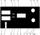
- a first embodiment of the tumble dryer according to the invention is shown in partial representation.
- the tumble dryer 2 is designed as a domestic appliance and comprises a process air circuit 4, shown only partially, for process air for drying laundry to be dried, a first refrigerant circuit 6 for a first refrigerant and a second refrigerant circuit 8 for a second refrigerant.
- the laundry, the process air, the first and the second refrigerant are in the Fig. 1 not shown.
- At the first and second refrigerants are each propane (other flammable refrigerants such as propene would also be possible), i.e. a flammable refrigerant.
- the first and second refrigerant circuits 6, 8 each have an evaporator 10, 12, a compressor 14, 16 fluidly connected to the evaporator 10, 12, a condenser 18, 20 fluidly connected to the compressor 14, 16 and one to the condenser 18 , 20 flow-conducting connected throttle 22, 24, the throttle 22, 24 being flow-connected to the corresponding evaporator 10, 12.
- the directions of flow in the first refrigerant circuit 6 and in the second refrigerant circuit 8 are each symbolized by arrows.
- the evaporator 10 of the first refrigerant circuit 6 and the condenser 20 of the second refrigerant circuit 8 are each arranged to transfer heat in the process air circuit 4 for the respective heat transfer with the process air.
- the condenser 18 of the first refrigerant circuit 6 and the evaporator 12 of the second refrigerant circuit 8 are in direct heat transfer connection with one another, the condenser 18 of the first refrigerant circuit 6 and the evaporator 12 of the second refrigerant circuit 8 being arranged outside the process air circuit 4. Please refer Fig. 1 .
- the direct heat transfer connection between the condenser 18 of the first refrigerant circuit 6 and the evaporator 12 of the second refrigerant circuit 8 is designed and arranged such that the first and second refrigerants flow in countercurrent to one another.
- the condenser 18 of the first refrigerant circuit 6 and the evaporator 12 of the second refrigerant circuit 8 are designed as a single structural unit 26.
- the evaporator 10 of the first refrigerant circuit 6 is arranged in front of the condenser 20 of the second refrigerant circuit 8, based on a flow direction of the process air in the process air circuit 4. See the in the Fig. 1 Process air circuit 4 symbolized as an arrow, the arrow simultaneously indicating the direction of flow of the process air in the process air circuit 4.
- the compressor 14 of the first refrigerant circuit 6 and the compressor 16 of the second refrigerant circuit 8 are each in heat transfer connection with a coolant, not shown, of a cooler 28, 30 of the tumble dryer 2.
- a flow direction of the respective coolant generated by the cooler 28, 30 is in the Fig. 1 symbolized by arrows 32, 34.
- the tumble dryer 2 is designed on the one hand in such a way that the pressure in the condenser 18 of the first refrigerant circuit 6 is higher than the pressure in the evaporator 12 of the second Refrigerant circuit 8 is.
- the tumble dryer 2 is designed such that a suction volume of the compressor 14 in the first refrigerant circuit 6 is greater than a suction volume of the compressor 16 in the second refrigerant circuit 8.
- the tumble dryer 2 is designed such that an evaporation capacity of the evaporator 12 of the second refrigerant circuit 8 is greater than an evaporation capacity of the evaporator 10 of the first refrigerant circuit 6.
- the evaporation capacities can also be the same.
- the compressor 14 of the first refrigerant circuit 6 draws in the superheated refrigerant from the evaporator 10 and compresses the refrigerant to a mean pressure that is lower than a high pressure in the second refrigerant circuit 8.
- the structural unit 26 which is designed as an internal heat exchanger of the tumble dryer 2
- the refrigerant condenses in the first refrigerant circuit 6, so that the resulting heat of condensation is used to evaporate the refrigerant of the second refrigerant circuit 8 in the evaporator 12. This is possible because the mean pressure of the refrigerant in the condenser 18 of the first refrigerant circuit 6, i.e.
- the condensing pressure in the structural unit 26 is higher than the pressure of the refrigerant in the evaporator 12 of the second refrigerant circuit 8, i.e. the evaporation pressure in the structural unit 26 , is.
- the refrigerant of the first refrigerant circuit 6 flows through the evaporator 10 of the first refrigerant circuit 6 and dehumidifies the process air of the process air circuit 4 so that the laundry exposed to the process air is dried in the tumble dryer 2 in the desired manner.
- the compressor 16 of the second refrigerant circuit 8 sucks in the superheated refrigerant from the evaporator 12 of the second refrigerant circuit 8, which is integrated in the structural unit 26, and compresses the refrigerant of the second refrigerant circuit 8 to the liquefaction pressure of the second refrigerant circuit 8, so that in the flow direction of the second Refrigerant circuit 8 the compressor 16 downstream condenser 20, the process air of the process air circuit is heated again.
- the condensed refrigerant of the second refrigerant circuit 8 is expanded through the throttle 24 and evaporated in the structural unit 26, that is to say in the internal heat exchanger of the tumble dryer 2, namely in the evaporator 12 of the second refrigerant circuit 8.
- the suction volume of the compressor 16 of the second refrigerant circuit 8 is less than the suction volume of the compressor 14 of the first refrigerant circuit 6.
- the compressor 14 of the first refrigerant circuit 6 and the compressor 16 of the second refrigerant circuit 8 are essentially switched on and switched off at the same time in each operating state of the tumble dryer 2.
- the heat is thus transferred between the condenser 18 of the first refrigerant circuit 6, which is integrated in the structural unit 26, and the evaporator 12 of the second refrigerant circuit 8, which is also integrated in the structural unit 26, outside the process air circuit 4 and directly.
- the tumble dryer 2 has coolers 28, 30, the compressor 14 of the first refrigerant circuit 6 being cooled with the cooler 28 and the compressor 16 of the second refrigerant circuit 8 being cooled with the cooler 30.
- the coolers 28, 30 can each be implemented as a fan for generating a coolant embodied as cooling air, namely ambient air.
- the evaporation capacity of the evaporator 12 of the second refrigerant circuit 8 is greater than the evaporation capacity of the evaporator 10 of the first refrigerant circuit 6, depending on the embodiment of the clothes dryer 2, i.e. depending on the design of the clothes dryer 2, even one Cooling of the first refrigerant circuit 6 can be dispensed with.
- Fig. 2 shows a second embodiment of the tumble dryer 2 according to the invention.
- the second embodiment largely corresponds to the first embodiment according to FIG Fig. 1 .
- the tumble dryer 2 according to the second exemplary embodiment does not have any coolers 28, 30 for the first and second refrigerant circuits 6, 8 for cooling the respective corresponding compressor 14, 16.
- first and second refrigerant circuits 6, 8 of the tumble dryer 2 according to the second exemplary embodiment, a heat exchanger 38, 40 connected in a coolant-conducting manner to a subcooler 36 of the tumble dryer 2 for subcooling the first and second refrigerants, the heat exchangers 38, 40 being arranged such that they can be cooled by means of a single coolant of the subcooler 36 are.
- This further reduces the effort involved in the manufacture and operation of the tumble dryer 2.
- the first refrigerant circuit 6 is in operation, while the second refrigerant circuit 8 is not in operation. See also Fig. 2 , in which a flow direction of the single coolant of the subcooler 36 for subcooling both the first and the second refrigerant is symbolized by an arrow 42.
- the subcooler 36 is a fan and the only coolant is cooling air, namely ambient air.
- other types of coolers and other types of coolants such as, for example, water cooling or the like, are basically also conceivable.
- the heat exchanger 38 arranged in the first coolant circuit 6 is arranged between the condenser 18 integrated in the structural unit 26 and the throttle 22 of the first coolant circuit 6, while the heat exchanger 40 arranged in the second coolant circuit 8 is arranged between the condenser 20 arranged in the process air circuit 4 and the Throttle 24 of the second refrigerant circuit 8 is arranged.
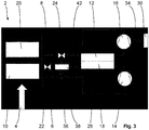
- a third embodiment of the tumble dryer according to the invention is shown.
- This third embodiment largely corresponds to the first and the second embodiment according to FIG Fig. 1 and 2 .
- the tumble dryer 2 according to the third exemplary embodiment does not have a cooler for the first refrigerant circuit 6 for cooling the corresponding compressor 14.
- a heat exchanger 38 connected in a coolant-conducting manner to a subcooler 36 of the tumble dryer 2 is arranged for subcooling the first refrigerant. See the Fig.
- the subcooler 36 in the first refrigerant circuit 6 may be necessary, for example, when the tumble dryer 2 is operated at high ambient temperatures. In this case, cooling of the refrigerant in the first refrigerant circuit 6 by means of a cooler 28 according to the first exemplary embodiment may not be sufficient.
- the subcooler 36 is a fan and the only coolant for cooling air, namely ambient air.
- the heat exchanger 38 arranged in the first refrigerant circuit 6 is arranged between the condenser 18 integrated in the structural unit 26 and the throttle 22 of the first refrigerant circuit 6.
- the invention according to the present exemplary embodiments it is possible to implement a high-performance laundry dryer with the simultaneous use of a flammable refrigerant.
- the time required for drying laundry by means of the laundry dryer according to the invention and the method according to the invention is significantly shortened, despite the fact that the fill quantity of flammable refrigerant is limited for safety reasons.
- the energy efficiency is increased in the tumble dryer according to the invention and in the method according to the invention, since the two refrigerant circuits can each be operated with only a small temperature lift.
- the tumble dryer according to the invention can be designed both as a household appliance and as a tumble dryer for commercial operation, that is to say for professional use.
- the tumble dryer according to the invention and the method according to the invention can also be used advantageously in tumble dryers for commercial operation, that is to say for professional use.
- the heat exchanger in the first refrigerant circuit and the heat exchanger in the second refrigerant circuit are cooled by means of mutually different subcoolers of the tumble dryer.
- the refrigerant in the first refrigerant circuit can be subcooled independently of the refrigerant in the second refrigerant circuit and the refrigerant in the second refrigerant circuit can be subcooled independently of the refrigerant in the first refrigerant circuit.
Landscapes
- Engineering & Computer Science (AREA)
- Physics & Mathematics (AREA)
- Mechanical Engineering (AREA)
- Thermal Sciences (AREA)
- General Engineering & Computer Science (AREA)
- Textile Engineering (AREA)
- Detail Structures Of Washing Machines And Dryers (AREA)
Abstract
Description
- Die Erfindung betrifft einen Wäschetrockner, umfassend einen Prozessluftkreislauf für eine Prozessluft zur Trocknung von zu trocknender Wäsche, einen ersten Kältemittelkreislauf für ein erstes Kältemittel und einen zweiten Kältemittelkreislauf für ein zweites Kältemittel, der im Oberbegriff des Patentanspruchs 1 genannten Art und ein Verfahren zu dessen Betrieb der im Oberbegriff des Patentanspruchs 12 genannten Art.
- Derartige Wärmepumpen-Wäschetrockner und Verfahren zu deren Betrieb sind aus dem Stand der Technik in einer Vielzahl von voneinander verschiedenen Ausführungsformen bereits vorbekannt. Die bekannten Wärmepumpen-Wäschetrockner umfassen einen Prozessluftkreislauf für eine Prozessluft zur Trocknung von zu trocknender Wäsche, einen ersten Kältemittelkreislauf für ein erstes Kältemittel und einen zweiten Kältemittelkreislauf für ein zweites Kältemittel, wobei der erste und der zweite Kältemittelkreislauf jeweils einen Verdampfer, einen mit dem Verdampfer strömungsleitend verbundenen Verdichter, einen mit dem Verdichter strömungsleitend verbundenen Verflüssiger und eine mit dem Verflüssiger strömungsleitend verbundene Drossel aufweisen, wobei die Drossel strömungsleitend mit dem Verdampfer verbunden ist und wobei der Verdampfer des ersten Kältemittelkreislaufs und der Verflüssiger des zweiten Kältemittelkreislaufs jeweils wärmeübertragend in dem Prozessluftkreislauf zur jeweiligen Wärmeübertragung mit der Prozessluft angeordnet sind. Die bekannten Wärmepumpen-Wäschetrockner werden insbesondere mit brennbaren Kältemitteln wie beispielsweise Propan betrieben, da diese Kältemittel im Vergleich zu anderen Kältemitteln, beispielsweise mit Fluorkohlenwasserstoffen, umweltfreundlich und preiswert sind. Auch die Verdichter und die auf dem Markt verfügbaren Wärmetauscher für die Verflüssigung und die Verdampfung des Kältemittels sind für brennbare Kältemittel kostengünstiger. Werden Wärmepumpen-Wäschetrockner mit einem brennbaren Kältemittel betrieben, so ist die Füllmenge aus Sicherheitsgründen und normativen Gründen jedoch auf 150 g Kältemittel je Kältemittelkreislauf begrenzt.
- Der Erfindung stellt sich somit das Problem, einen Wäschetrockner und ein Verfahren zur Wäschetrocknung zu verbessern.
- Erfindungsgemäß wird dieses Problem durch einen Wäschetrockner mit den Merkmalen des Patentanspruchs 1 gelöst, der dadurch gekennzeichnet ist, dass der Verflüssiger des ersten Kältemittelkreislaufs und der Verdampfer des zweiten Kältemittelkreislaufs miteinander in direkter Wärmeübertragungsverbindung stehen, wobei der Verflüssiger des ersten Kältemittelkreislaufs und der Verdampfer des zweiten Kältemittelkreislaufs außerhalb des Prozessluftkreislaufs angeordnet sind. Ferner wird dieses Problem durch ein Verfahren zum Betrieb eines derartigen Wäschetrockners mit den Merkmalen des Patentanspruchs 12 gelöst. Vorteilhafte Ausgestaltungen und Weiterbildungen der Erfindung ergeben sich aus den nachfolgenden Unteransprüchen.
- Der mit der Erfindung erreichbare Vorteil besteht insbesondere darin, dass ein Wäschetrockner und ein Verfahren zur Wäschetrocknung verbessert sind. Mittels der Erfindung ist es möglich, einen leistungsstarken Wäschetrockner bei gleichzeitiger Verwendung eines brennbaren Kältemittels zu realisieren. Entsprechend ist die für eine Wäschetrocknung mittels des erfindungsgemäßen Wäschetrockners und des erfindungsgemäßen Verfahrens erforderliche Zeitdauer, trotz der aus Sicherheitsgründen und normativen Gründen begrenzten Füllmenge von brennbarem Kältemittel, wesentlich verkürzt. Ferner ist die Energieeffizienz bei dem erfindungsgemäßen Wäschetrockner und bei dem erfindungsgemäßen Verfahren gesteigert, da die beiden Kältemittelkreisläufe jeweils mit einem lediglich geringen Temperaturhub betreibbar sind. Der erfindungsgemäße Wäschetrockner kann dabei sowohl als ein Haushaltsgerät wie auch als ein Wäschetrockner für den gewerblichen Betrieb, also für den professionellen Einsatz, ausgebildet sein.
- Grundsätzlich ist der erfindungsgemäße Wäschetrockner in weiten geeigneten Grenzen frei wählbar. Eine vorteilhafte Weiterbildung des erfindungsgemäßen Wäschetrockners sieht vor, dass die direkte Wärmeübertragungsverbindung zwischen dem Verflüssiger des ersten Kältemittelkreislaufs und dem Verdampfer des zweiten Kältemittelkreislaufs derart ausgebildet und angeordnet ist, dass das erste und das zweite Kältemittel zueinander im Gegenstrom strömen. Hierdurch ist es möglich, die Füllmengen an Kältemittel in den Kältemittelkreisläufen weiter zu reduzieren. Die Füllmenge an Kältemittel kann darüber hinaus auch noch durch weitere Maßnahmen, beispielsweise durch die guten Wärmeübertragungseigenschaften des ausgewählten Kältemittels, in gewünschter Weise verringert werden. Denkbar ist jedoch auch, dass die direkte Wärmeübertragungsverbindung zwischen dem Verflüssiger des ersten Kältemittelkreislaufs und dem Verdampfer des zweiten Kältemittelkreislaufs derart ausgebildet und angeordnet ist, dass das erste und das zweite Kältemittel zueinander im Gleichstrom strömen.
- Eine weitere vorteilhafte Weiterbildung des erfindungsgemäßen Wäschetrockners sieht vor, dass der Verflüssiger des ersten Kältemittelkreislaufs und der Verdampfer des zweiten Kältemittelkreislaufs als eine einzige Baueinheit ausgebildet sind. Auf diese Weise ist die Kompaktheit der Anordnung des Verflüssigers des ersten Kältemittelkreislaufs und des Verdampfers des zweiten Kältemittelkreislaufs verbessert und damit deren Platzbedarf reduziert. Ferner ist dadurch die Handhabung der vorgenannten Anordnung bei der Herstellung des Wäschetrockners, beispielsweise bei der Lagerhaltung und bei der Montage, wesentlich verbessert.
- Eine andere vorteilhafte Weiterbildung des erfindungsgemäßen Wäschetrockners sieht vor, dass der Verdampfer des ersten Kältemittelkreislaufs, bezogen auf eine Strömungsrichtung der Prozessluft in dem Prozessluftkreislauf, vor dem Verflüssiger des zweiten Kältemittelkreislaufs angeordnet ist.
- Eine weitere vorteilhafte Weiterbildung des erfindungsgemäßen Wäschetrockners sieht vor, dass der Verdichter des ersten Kältemittelkreislaufs und/oder der Verdichter des zweiten Kältemittelkreislaufs in Wärmeübertragungsverbindung mit einem Kühlmittel mindestens eines Kühlers des Wäschetrockners stehen/steht. Auf diese Weise ist es möglich, das Kältemittel in dem jeweiligen Kältemittelkreislauf bedarfsweise zu kühlen.
- Alternativ oder zusätzlich zu der vorgenannten Ausführungsform sieht eine andere vorteilhafte Weiterbildung des erfindungsgemäßen Wäschetrockners vor, dass in dem ersten Kältemittelkreislauf und/oder in dem zweiten Kältemittelkreislauf ein mit einem Unterkühler des Wäschetrockners kühlmittelleitend verbundener Wärmetauscher zur Unterkühlung des ersten und/oder des zweiten Kältemittels angeordnet ist.
- Eine vorteilhafte Weiterbildung der letztgenannten Ausführungsform des erfindungsgemäßen Wäschetrockners sieht vor, dass in dem ersten Kältemittelkreislauf und in dem zweiten Kältemittelkreislauf jeweils ein Wärmetauscher angeordnet ist, wobei die Wärmetauscher derart angeordnet sind, dass diese mittels eines einzigen Kühlmittels des Unterkühlers kühlbar sind. Hierdurch ist der Aufwand bei der Herstellung und bei dem Betrieb des erfindungsgemäßen Wäschetrockners weiter reduziert.
- Eine besonders vorteilhafte Weiterbildung der beiden letztgenannten Ausführungsformen des erfindungsgemäßen Wäschetrockners sieht vor, dass der in dem ersten Kältemittelkreislauf angeordnete Wärmetauscher zwischen dem Verflüssiger und der Drossel des ersten Kältemittelkreislaufs angeordnet ist. Auf diese Weise ist es möglich, die Prozessluft in dem Prozessluftkreislauf zusätzlich mittels dieses Wärmetauschers in gewünschter Weise abzukühlen. Entsprechend ist die erforderliche Zeitdauer zur Abkühlung der Prozessluft weiter verringert.
- Eine weitere vorteilhafte Weiterbildung des erfindungsgemäßen Wäschetrockners sieht vor, dass der Wäschetrockner derart ausgelegt ist, dass der Druck in dem Verflüssiger des ersten Kältemittelkreislaufs höher als der Druck in dem Verdampfer des zweiten Kältemittelkreislaufs ist. Hierdurch ist eine Wärmeübertragung von dem Verflüssiger des ersten Kältemittelkreislaufs auf den Verdampfer des zweiten Kältemittelkreislaufs auf einfache Weise realisiert.
- Eine andere vorteilhafte Weiterbildung des erfindungsgemäßen Wäschetrockners sieht vor, dass der Wäschetrockner derart ausgelegt ist, dass ein Ansaugvolumen des Verdichters in dem ersten Kältemittelkreislauf größer als ein Ansaugvolumen des Verdichters in dem zweiten Kältemittelkreislauf ist.
- Ferner sieht eine weitere vorteilhafte Weiterbildung des erfindungsgemäßen Wäschetrockners vor, dass der Wäschetrockner derart ausgelegt ist, dass eine Verdampfungsleistung des Verdampfers des zweiten Kältemittelkreislaufs größer als eine Verdampfungsleistung des Verdampfers des ersten Kältemittelkreislaufs ist. Hierdurch ist es möglich, dass auf eine Kühlung des ersten Kältemittelkreislaufs verzichtet werden kann. Entsprechend vereinfacht sich der Aufbau des erfindungsgemäßen Wäschetrockners zusätzlich.
- Grundsätzlich ist das erfindungsgemäße Verfahren zum Betrieb des erfindungsgemäßen Wäschetrockners in weiten geeigneten Grenzen frei wählbar. Zweckmäßigerweise ist es vorgesehen, dass der Verdichter des ersten Kältemittelkreislaufs und der Verdichter des zweiten Kältemittelkreislaufs in einem Betriebszustand des Wäschetrockners, bevorzugt in jedem Betriebszustand des Wäschetrockners, im Wesentlichen gleichzeitig eingeschaltet und gleichzeitig ausgeschaltet werden.
- Drei Ausführungsbeispiele der Erfindung sind in den Zeichnungen rein schematisch dargestellt und werden nachfolgend näher beschrieben. Es zeigt
- Figur 1
- ein erstes Ausführungsbeispiel des erfindungsgemäßen Wäschetrockners in einer teilweisen Darstellung,
- Figur 2
- ein zweites Ausführungsbeispiel des erfindungsgemäßen Wäschetrockners in einer teilweisen Darstellung und
- Figur 3
- ein drittes Ausführungsbeispiel des erfindungsgemäßen Wäschetrockners in einer teilweisen Darstellung.
- In der
Fig. 1 ist ein erstes Ausführungsbeispiel des erfindungsgemäßen Wäschetrockners in teilweiser Darstellung gezeigt. Der Wäschetrockner 2 ist als ein Haushaltsgerät ausgebildet und umfasst einen lediglich teilweise dargestellten Prozessluftkreislauf 4 für eine Prozessluft zur Trocknung von zu trocknender Wäsche, einen ersten Kältemittelkreislauf 6 für ein erstes Kältemittel und einen zweiten Kältemittelkreislauf 8 für ein zweites Kältemittel. Die Wäsche, die Prozessluft, das erste und das zweite Kältemittel sind in derFig. 1 nicht dargestellt. Bei dem ersten und dem zweiten Kältemittel handelt es sich jeweils um Propan (andere brennbare Kältemittel wie z.B. Propen wären auch möglich), also um ein brennbares Kältemittel. Der erste und der zweite Kältemittelkreislauf 6, 8 weisen jeweils einen Verdampfer 10, 12, einen mit dem Verdampfer 10, 12 strömungsleitend verbundenen Verdichter 14, 16, einen mit dem Verdichter 14, 16 strömungsleitend verbundenen Verflüssiger 18, 20 und eine mit dem Verflüssiger 18, 20 strömungsleitend verbundene Drossel 22, 24 auf, wobei die Drossel 22, 24 strömungsleitend mit dem korrespondierenden Verdampfer 10, 12 verbunden ist. Die Strömungsrichtungen in dem ersten Kältemittelkreislauf 6 und in dem zweiten Kältemittelkreislauf 8 sind jeweils durch Pfeile symbolisiert. - Der Verdampfer 10 des ersten Kältemittelkreislaufs 6 und der Verflüssiger 20 des zweiten Kältemittelkreislaufs 8 sind jeweils wärmeübertragend in dem Prozessluftkreislauf 4 zur jeweiligen Wärmeübertragung mit der Prozessluft angeordnet. Der Verflüssiger 18 des ersten Kältemittelkreislaufs 6 und der Verdampfer 12 des zweiten Kältemittelkreislaufs 8 stehen miteinander in direkter Wärmeübertragungsverbindung, wobei der Verflüssiger 18 des ersten Kältemittelkreislaufs 6 und der Verdampfer 12 des zweiten Kältemittelkreislaufs 8 außerhalb des Prozessluftkreislaufs 4 angeordnet sind. Siehe
Fig. 1 . - Bei dem vorliegenden Ausführungsbeispiel ist die direkte Wärmeübertragungsverbindung zwischen dem Verflüssiger 18 des ersten Kältemittelkreislaufs 6 und dem Verdampfer 12 des zweiten Kältemittelkreislaufs 8 derart ausgebildet und angeordnet, dass das erste und das zweite Kältemittel zueinander im Gegenstrom strömen. Darüber hinaus sind der Verflüssiger 18 des ersten Kältemittelkreislaufs 6 und der Verdampfer 12 des zweiten Kältemittelkreislaufs 8 als eine einzige Baueinheit 26 ausgebildet.
- Wie ferner aus der
Fig. 1 ersichtlich ist, ist der Verdampfer 10 des ersten Kältemittelkreislaufs 6, bezogen auf eine Strömungsrichtung der Prozessluft in dem Prozessluftkreislauf 4, vor dem Verflüssiger 20 des zweiten Kältemittelkreislaufs 8 angeordnet. Siehe hierzu den in derFig. 1 als Pfeil symbolisierten Prozessluftkreislauf 4, wobei der Pfeil gleichzeitig die Strömungsrichtung der Prozessluft in dem Prozessluftkreislauf 4 angibt. - Der Verdichter 14 des ersten Kältemittelkreislaufs 6 und der Verdichter 16 des zweiten Kältemittelkreislaufs 8 stehen jeweils in Wärmeübertragungsverbindung mit einem nicht dargestellten Kühlmittel eines Kühlers 28, 30 des Wäschetrockners 2. Eine Strömungsrichtung des jeweiligen von dem Kühler 28, 30 erzeugten Kühlmittels ist in der
Fig. 1 durch Pfeile 32, 34 symbolisiert. - Darüber hinaus ist der Wäschetrockner 2 bei dem vorliegenden Ausführungsbeispiel zum einen derart ausgelegt, dass der Druck in dem Verflüssiger 18 des ersten Kältemittelkreislaufs 6 höher als der Druck in dem Verdampfer 12 des zweiten Kältemittelkreislaufs 8 ist. Zum anderen ist der Wäschetrockner 2 derart ausgelegt, dass ein Ansaugvolumen des Verdichters 14 in dem ersten Kältemittelkreislauf 6 größer als ein Ansaugvolumen des Verdichters 16 in dem zweiten Kältemittelkreislauf 8 ist. Ferner ist der Wäschetrockner 2 derart ausgelegt, dass eine Verdampfungsleistung des Verdampfers 12 des zweiten Kältemittelkreislaufs 8 größer als eine Verdampfungsleistung des Verdampfers 10 des ersten Kältemittelkreislaufs 6 ist. Alternativ können die Verdampfungsleistungen auch gleich sein.
- Nachfolgend wird die Funktionsweise des erfindungsgemäßen Wäschetrockners und des erfindungsgemäßen Verfahrens gemäß dem ersten Ausführungsbeispiel anhand der
Fig. 1 näher erläutert. - Der Verdichter 14 des ersten Kältemittelkreislaufs 6 saugt das überhitzte Kältemittel von dem Verdampfer 10 an und komprimiert das Kältemittel auf einen mittleren Druck, der geringer als ein Hochdruck in dem zweiten Kältemittelkreislauf 8 ist. In der Baueinheit 26, die als ein innerer Wärmeübertrager des Wäschetrockners 2 ausgebildet ist, kondensiert das Kältemittel in dem ersten Kältemittelkreislauf 6, so dass die dabei entstehende Kondensationswärme für das Verdampfen des Kältemittels des zweiten Kältemittelkreislaufs 8 in dem Verdampfer 12 genutzt wird. Dies ist deshalb möglich, weil der mittlere Druck des Kältemittels in dem Verflüssiger 18 des ersten Kältemittelkreislaufs 6, also der Verflüssigungsdruck in der Baueinheit 26, höher als der Druck des Kältemittels in dem Verdampfer 12 des zweiten Kältemittelkreislaufs 8, also der Verdampfungsdruck in der Baueinheit 26, ist. Nach der Entspannung in der Drossel 22 des ersten Kältemittelkreislaufs 6 durchströmt das Kältemittel des ersten Kältemittelkreislaufs 6 den Verdampfer 10 des ersten Kältemittelkreislaufs 6 und entfeuchtet die Prozessluft des Prozessluftkreislaufs 4, so dass die der Prozessluft ausgesetzte Wäsche in dem Wäschetrockner 2 in gewünschter Weise getrocknet wird.
- Der Verdichter 16 des zweiten Kältemittelkreislaufs 8 saugt das überhitzte Kältemittel von dem in der Baueinheit 26 integrierten Verdampfer 12 des zweiten Kältemittelkreislaufs 8 an und komprimiert das Kältemittel des zweiten Kältemittelkreislaufs 8 auf den Verflüssigungsdruck des zweiten Kältemittelkreislaufs 8, so dass in dem in der Strömungsrichtung des zweiten Kältemittelkreislaufs 8 dem Verdichter 16 nachgeschalteten Verflüssiger 20 die Prozessluft des Prozessluftkreislaufs wieder erwärmt wird. Das kondensierte Kältemittel des zweiten Kältemittelkreislaufs 8 wird durch die Drossel 24 entspannt und in der Baueinheit 26, also in dem inneren Wärmeübertrager des Wäschetrockners 2, nämlich in dem Verdampfer 12 des zweiten Kältemittelkreislaufs 8, verdampft. Wie oben bereits ausgeführt, ist das Ansaugvolumen des Verdichters 16 des zweiten Kältemittelkreislaufs 8 geringer als das Ansaugvolumen des Verdichters 14 des ersten Kältemittelkreislaufs 6. Bei dem vorliegenden Ausführungsbeispiel ist es vorgesehen, dass der Verdichter 14 des ersten Kältemittelkreislaufs 6 und der Verdichter 16 des zweiten Kältemittelkreislaufs 8 in jedem Betriebszustand des Wäschetrockners 2 im Wesentlichen gleichzeitig eingeschaltet und gleichzeitig ausgeschaltet werden.
- Somit wird die Wärme zwischen dem in der Baueinheit 26 integrierten Verflüssiger 18 des ersten Kältemittelkreislaufs 6 und dem ebenfalls in der Baueinheit 26 integrierten Verdampfer 12 des zweiten Kältemittelkreislaufs 8 außerhalb des Prozessluftkreislaufs 4 und direkt übertragen.
- Während des Betriebs des erfindungsgemäßen Wäschetrockners 2 gemäß dem vorliegenden Ausführungsbeispiel kann es erforderlich sein, dass die Kältemittel in dem ersten und in dem zweiten Kältemittelkreislauf 6, 8 gekühlt werden müssen. Hierfür weist der Wäschetrockner 2 die Kühler 28, 30 auf, wobei mit dem Kühler 28 der Verdichter 14 des ersten Kältemittelkreislaufs 6 und mit dem Kühler 30 der Verdichter 16 des zweiten Kältemittelkreislaufs 8 gekühlt wird. Auf diese Weise ist es möglich, das Kältemittel in dem jeweiligen Kältemittelkreislauf bedarfsweise zu kühlen. Beispielsweise können die Kühler 28, 30 jeweils als ein Gebläse zur Erzeugung eines als Kühlluft, nämlich Umgebungsluft, ausgebildeten Kühlmittels realisiert sein. Grundsätzlich denkbar sind aber auch andere Arten von Kühlern und andere Arten von Kühlmitteln, wie beispielsweise eine Wasserkühlung oder dergleichen. Da bei dem vorliegenden Ausführungsbeispiel des erfindungsgemäßen Wäschetrockners 2 die Verdampfungsleistung des Verdampfers 12 des zweiten Kältemittelkreislaufs 8 größer als die Verdampfungsleistung des Verdampfers 10 des ersten Kältemittelkreislaufs 6 ist, kann je nach Ausführungsform des Wäschetrockners 2, also je nach Auslegung des Wäschetrockners 2, sogar auf eine Kühlung des ersten Kältemittelkreislaufs 6 verzichtet werden.
- Im Folgenden werden zwei weitere Ausführungsbeispiele des erfindungsgemäßen Wäschetrockners anhand der
Fig. 2 und3 näher erläutert, wobei die Beschreibung des zweiten und des dritten Ausführungsbeispiels auf die Unterschiede zu den jeweils vorgenannten Ausführungsbeispielen beschränkt ist. Ansonsten wird auf die Ausführungen zu diesen jeweils vorgenannten Ausführungsbeispielen verwiesen. Gleiche oder gleichwirkende Bauteile sind mit den gleichen Bezugszeichen versehen. -
Fig. 2 zeigt ein zweites Ausführungsbeispiel des erfindungsgemäßen Wäschetrockners 2. Wie aus einer Zusammenschau derFig. 1 und2 hervorgeht, entspricht das zweite Ausführungsbeispiel weitgehend dem ersten Ausführungsbeispiel gemäß derFig. 1 . Im Unterschied zu dem ersten Ausführungsbeispiel weist der Wäschetrockner 2 gemäß dem zweiten Ausführungsbeispiel keine Kühler 28, 30 für den ersten und den zweiten Kältemittelkreislauf 6, 8 zur Kühlung des jeweils korrespondierenden Verdichters 14, 16 auf. Stattdessen ist in dem ersten und dem zweiten Kältemittelkreislauf 6, 8 des Wäschetrockners 2 gemäß dem zweiten Ausführungsbeispiel jeweils ein mit einem Unterkühler 36 des Wäschetrockners 2 kühlmittelleitend verbundener Wärmetauscher 38, 40 zur Unterkühlung des ersten und des zweiten Kältemittels angeordnet, wobei die Wärmetauscher 38, 40 derart angeordnet sind, dass diese mittels eines einzigen Kühlmittels des Unterkühlers 36 kühlbar sind. Hierdurch ist der Aufwand bei der Herstellung und bei dem Betrieb des Wäschetrockners 2 weiter reduziert. Ferner ist es auf diese Weise möglich, die Prozessluft in dem Prozessluftkreislauf 4 zusätzlich mittels des Wärmetauschers 38 in gewünschter Weise direkt abzukühlen. Entsprechend ist die erforderliche Zeitdauer zur Abkühlung der Prozessluft weiter verringert. - Für das vorgenannte thermodynamische Abkühlen der Prozessluft des Prozessluftkreislaufs 4 ist der erste Kältemittelkreislauf 6 in Betrieb, während der zweite Kältemittelkreislauf 8 nicht in Betrieb ist. Siehe hierzu
Fig. 2 , in der eine Strömungsrichtung des einzigen Kühlmittels des Unterkühlers 36 zur Unterkühlung sowohl des ersten wie auch des zweiten Kältemittels mit einem Pfeil 42 symbolisiert ist. Analog zu dem ersten Ausführungsbeispiel handelt es sich bei dem Unterkühler 36 um ein Gebläse und bei dem einzigen Kühlmittel um Kühlluft, nämlich Umgebungsluft. Wie oben bereits ausgeführt sind aber auch andere Arten von Kühlern und andere Arten von Kühlmitteln, wie beispielsweise eine Wasserkühlung oder dergleichen, grundsätzlich denkbar. Der in dem ersten Kältemittelkreislauf 6 angeordnete Wärmetauscher 38 ist zwischen dem in der Baueinheit 26 integrierten Verflüssiger 18 und der Drossel 22 des ersten Kältemittelkreislaufs 6 angeordnet, während der in dem zweiten Kältemittelkreislauf 8 angeordnete Wärmetauscher 40 zwischen dem in dem Prozessluftkreislauf 4 angeordneten Verflüssiger 20 und der Drossel 24 des zweiten Kältemittelkreislaufs 8 angeordnet ist. - In der
Fig. 3 ist ein drittes Ausführungsbeispiel des erfindungsgemäßen Wäschetrockners dargestellt. Dieses dritte Ausführungsbeispiel entspricht weitgehend dem ersten und dem zweiten Ausführungsbeispiel gemäß derFig. 1 und2 . Im Unterschied zu dem ersten Ausführungsbeispiel weist der Wäschetrockner 2 gemäß dem dritten Ausführungsbeispiel keinen Kühler für den ersten Kältemittelkreislauf 6 zur Kühlung des korrespondierenden Verdichters 14 auf. Stattdessen ist in dem ersten Kältemittelkreislauf 6 des Wäschetrockners 2 gemäß dem dritten Ausführungsbeispiel ein mit einem Unterkühler 36 des Wäschetrockners 2 kühlmittelleitend verbundener Wärmetauscher 38 zur Unterkühlung des ersten Kältemittels angeordnet. Siehe hierzu dieFig. 3 , in der eine Strömungsrichtung des Kühlmittels des Unterkühlers 36 zur Unterkühlung des ersten Kältemittels mit einem Pfeil 42 symbolisiert ist. Der Unterkühler 36 in dem ersten Kältemittelkreislauf 6 kann beispielsweise erforderlich sein, wenn der Wäschetrockner 2 bei hohen Umgebungstemperaturen betrieben wird. In diesem Fall kann eine Kühlung des Kältemittels in dem ersten Kältemittelkreislauf 6 mittels eines Kühlers 28 gemäß dem ersten Ausführungsbeispiel nicht ausreichend sein. Analog zu dem zweiten Ausführungsbeispiel handelt es sich bei dem Unterkühler 36 um ein Gebläse und bei dem einzigen Kühlmittel um Kühlluft, nämlich Umgebungsluft. Wie zu dem ersten und dem zweiten Ausführungsbeispiel bereits ausgeführt sind aber auch andere Arten von Kühlern und andere Arten von Kühlmitteln, wie beispielsweise eine Wasserkühlung oder dergleichen, grundsätzlich denkbar. Der in dem ersten Kältemittelkreislauf 6 angeordnete Wärmetauscher 38 ist zwischen dem in der Baueinheit 26 integrierten Verflüssiger 18 und der Drossel 22 des ersten Kältemittelkreislaufs 6 angeordnet. - Mittels der Erfindung gemäß den vorliegenden Ausführungsbeispielen ist es möglich, einen leistungsstarken Wäschetrockner bei gleichzeitiger Verwendung eines brennbaren Kältemittels zu realisieren. Entsprechend ist die für eine Wäschetrocknung mittels des erfindungsgemäßen Wäschetrockners und des erfindungsgemäßen Verfahrens erforderliche Zeitdauer, trotz der aus Sicherheitsgründen begrenzten Füllmenge von brennbaren Kältemittel, wesentlich verkürzt. Ferner ist die Energieeffizienz bei dem erfindungsgemäßen Wäschetrockner und bei dem erfindungsgemäßen Verfahren gesteigert, da die beiden Kältemittelkreisläufe jeweils mit einem lediglich geringen Temperaturhub betreibbar sind. Der erfindungsgemäße Wäschetrockner kann dabei sowohl als ein Haushaltsgerät wie auch als ein Wäschetrockner für den gewerblichen Betrieb, also für den professionellen Einsatz, ausgebildet sein.
- Die Erfindung ist nicht auf die vorliegenden Ausführungsbeispiele begrenzt. Wie oben ausgeführt, sind der erfindungsgemäße Wäschetrockner und das erfindungsgemäße Verfahren auch bei Wäschetrocknern für den gewerblichen Betrieb, also den professionellen Einsatz, vorteilhaft verwendbar. Ferner ist es denkbar, dass beispielsweise der Wärmetauscher in dem ersten Kältemittelkreislauf und der Wärmetauscher in dem zweiten Kältemittelkreislauf mittels voneinander verschiedener Unterkühler des Wäschetrockners gekühlt werden. Entsprechend kann das Kältemittel in dem ersten Kältemittelkreislauf unabhängig von dem Kältemittel in dem zweiten Kältemittelkreislauf und das Kältemittel in dem zweiten Kältemittelkreislauf unabhängig von dem Kältemittel in dem ersten Kältemittelkreislauf unterkühlt werden.
Claims (13)
- Wäschetrockner (2), umfassend einen Prozessluftkreislauf (4) für eine Prozessluft zur Trocknung von zu trocknender Wäsche, einen ersten Kältemittelkreislauf (6) für ein erstes Kältemittel und einen zweiten Kältemittelkreislauf (8) für ein zweites Kältemittel, wobei der erste und der zweite Kältemittelkreislauf (6, 8) jeweils einen Verdampfer (10, 12), einen mit dem Verdampfer (10, 12) strömungsleitend verbundenen Verdichter (14, 16), einen mit dem Verdichter (14, 16) strömungsleitend verbundenen Verflüssiger (18, 20) und eine mit dem Verflüssiger (18, 20) strömungsleitend verbundene Drossel (22, 24) aufweisen, wobei die Drossel (22, 24) strömungsleitend mit dem Verdampfer (10, 12) verbunden ist und wobei der Verdampfer (10) des ersten Kältemittelkreislaufs (6) und der Verflüssiger (20) des zweiten Kältemittelkreislaufs (8) jeweils wärmeübertragend in dem Prozessluftkreislauf (4) zur jeweiligen Wärmeübertragung mit der Prozessluft angeordnet sind, dadurch gekennzeichnet, dass der Verflüssiger (18) des ersten Kältemittelkreislaufs (6) und der Verdampfer (12) des zweiten Kältemittelkreislaufs (8) miteinander in direkter Wärmeübertragungsverbindung stehen, wobei der Verflüssiger (18) des ersten Kältemittelkreislaufs (6) und der Verdampfer (12) des zweiten Kältemittelkreislaufs (8) außerhalb des Prozessluftkreislaufs (4) angeordnet sind.
- Wäschetrockner (2) nach Anspruch 1, dadurch gekennzeichnet, dass die direkte Wärmeübertragungsverbindung zwischen dem Verflüssiger (18) des ersten Kältemittelkreislaufs (6) und dem Verdampfer (12) des zweiten Kältemittelkreislaufs (8) derart ausgebildet und angeordnet ist, dass das erste und das zweite Kältemittel zueinander im Gegenstrom strömen.
- Wäschetrockner (2) nach Anspruch 1 oder 2, dadurch gekennzeichnet, dass der Verflüssiger (18) des ersten Kältemittelkreislaufs (6) und der Verdampfer (12) des zweiten Kältemittelkreislaufs (8) als eine einzige Baueinheit (26) ausgebildet sind.
- Wäschetrockner (2) nach einem der Ansprüche 1 bis 3, dadurch gekennzeichnet, dass der Verdampfer (10) des ersten Kältemittelkreislaufs (6), bezogen auf eine Strömungsrichtung der Prozessluft in dem Prozessluftkreislauf (4), vor dem Verflüssiger (20) des zweiten Kältemittelkreislaufs (8) angeordnet ist.
- Wäschetrockner (2) nach einem der Ansprüche 1 bis 4, dadurch gekennzeichnet, dass der Verdichter (14) des ersten Kältemittelkreislaufs (6) und/oder der Verdichter (16) des zweiten Kältemittelkreislaufs (8) in Wärmeübertragungsverbindung mit einem Kühlmittel mindestens eines Kühlers (28, 30) des Wäschetrockners (2) stehen/steht.
- Wäschetrockner (2) nach einem der Ansprüche 1 bis 5, dadurch gekennzeichnet, dass in dem ersten Kältemittelkreislauf (6) und/oder in dem zweiten Kältemittelkreislauf (8) ein mit einem Unterkühler (36) des Wäschetrockners (2) kühlmittelleitend verbundener Wärmetauscher (38, 40) zur Unterkühlung des ersten und/oder des zweiten Kältemittels angeordnet ist.
- Wäschetrockner (2) nach Anspruch 6, dadurch gekennzeichnet, dass in dem ersten Kältemittelkreislauf (6) und in dem zweiten Kältemittelkreislauf (8) jeweils ein Wärmetauscher (38, 40) angeordnet ist, wobei die Wärmetauscher (38, 40) derart angeordnet sind, dass diese mittels eines einzigen Kühlmittels des Unterkühlers (36) kühlbar sind.
- Wäschetrockner (2) nach Anspruch 6 oder 7, dadurch gekennzeichnet, dass der in dem ersten Kältemittelkreislauf (6) angeordnete Wärmetauscher (38) zwischen dem Verflüssiger (18) und der Drossel (22) des ersten Kältemittelkreislaufs (6) angeordnet ist.
- Wäschetrockner (2) nach einem der Ansprüche 1 bis 8, dadurch gekennzeichnet, dass der Wäschetrockner (2) derart ausgelegt ist, dass der Druck in dem Verflüssiger (18) des ersten Kältemittelkreislaufs (6) höher als der Druck in dem Verdampfer (12) des zweiten Kältemittelkreislaufs (8) ist.
- Wäschetrockner (2) nach einem der Ansprüche 1 bis 9, dadurch gekennzeichnet, dass der Wäschetrockner (2) derart ausgelegt ist, dass ein Ansaugvolumen des Verdichters (14) in dem ersten Kältemittelkreislauf (6) größer als ein Ansaugvolumen des Verdichters (16) in dem zweiten Kältemittelkreislauf (8) ist.
- Wäschetrockner (2) nach einem der Ansprüche 1 bis 10, dadurch gekennzeichnet, dass der Wäschetrockner (2) derart ausgelegt ist, dass eine Verdampfungsleistung des Verdampfers (12) des zweiten Kältemittelkreislaufs (8) größer als eine Verdampfungsleistung des Verdampfers (10) des ersten Kältemittelkreislaufs (6) ist.
- Verfahren zum Betrieb eines Wäschetrockners (2) nach dem Oberbegriff des Anspruchs 1, dadurch gekennzeichnet, dass der Wäschetrockner (2) nach einem der Ansprüche 1 bis 11 ausgebildet ist und zwischen dem Verflüssiger (18) des ersten Kältemittelkreislaufs (6) und dem Verdampfer (12) des zweiten Kältemittelkreislaufs (8) außerhalb des Prozessluftkreislaufs (4) direkt Wärme übertragen wird.
- Verfahren nach Anspruch 12, dadurch gekennzeichnet, dass der Verdichter (14) des ersten Kältemittelkreislaufs (6) und der Verdichter (16) des zweiten Kältemittelkreislaufs (8) in einem Betriebszustand des Wäschetrockners (2), bevorzugt in jedem Betriebszustand des Wäschetrockners (2), im Wesentlichen gleichzeitig eingeschaltet und gleichzeitig ausgeschaltet werden.
Applications Claiming Priority (1)
| Application Number | Priority Date | Filing Date | Title |
|---|---|---|---|
| DE102019123941.9A DE102019123941A1 (de) | 2019-09-06 | 2019-09-06 | Wärmepumpen-Wäschetrockner und Verfahren zu dessen Betrieb |
Publications (2)
| Publication Number | Publication Date |
|---|---|
| EP3789533A1 true EP3789533A1 (de) | 2021-03-10 |
| EP3789533B1 EP3789533B1 (de) | 2023-05-24 |
Family
ID=72234683
Family Applications (1)
| Application Number | Title | Priority Date | Filing Date |
|---|---|---|---|
| EP20192349.7A Active EP3789533B1 (de) | 2019-09-06 | 2020-08-24 | Wärmepumpen-wäschetrockner und verfahren zu dessen betrieb |
Country Status (2)
| Country | Link |
|---|---|
| EP (1) | EP3789533B1 (de) |
| DE (1) | DE102019123941A1 (de) |
Cited By (1)
| Publication number | Priority date | Publication date | Assignee | Title |
|---|---|---|---|---|
| CN116067030A (zh) * | 2022-12-30 | 2023-05-05 | 郑州之铂环境科技有限公司 | 一种烘干用复叠式超高温出风热泵空调器及其控制方法 |
Citations (3)
| Publication number | Priority date | Publication date | Assignee | Title |
|---|---|---|---|---|
| EP2067890A1 (de) * | 2007-12-03 | 2009-06-10 | BSH Bosch und Siemens Hausgeräte GmbH | Trockner mit einer Wärmepumpe und mindestens einer sekundären Fluidschaltung |
| EP2122040A1 (de) * | 2008-02-27 | 2009-11-25 | IMAT S.p.A. | Kleidertrockner mit heizpumpe |
| US20100147006A1 (en) * | 2007-06-04 | 2010-06-17 | Taras Michael F | Refrigerant system with cascaded circuits and performance enhancement features |
Family Cites Families (2)
| Publication number | Priority date | Publication date | Assignee | Title |
|---|---|---|---|---|
| EP2147999A1 (de) * | 2008-07-24 | 2010-01-27 | Electrolux Home Products Corporation N.V. | Haushaltswäschetrockner |
| KR101613966B1 (ko) * | 2014-12-29 | 2016-04-20 | 엘지전자 주식회사 | 의류처리장치 |
-
2019
- 2019-09-06 DE DE102019123941.9A patent/DE102019123941A1/de not_active Withdrawn
-
2020
- 2020-08-24 EP EP20192349.7A patent/EP3789533B1/de active Active
Patent Citations (3)
| Publication number | Priority date | Publication date | Assignee | Title |
|---|---|---|---|---|
| US20100147006A1 (en) * | 2007-06-04 | 2010-06-17 | Taras Michael F | Refrigerant system with cascaded circuits and performance enhancement features |
| EP2067890A1 (de) * | 2007-12-03 | 2009-06-10 | BSH Bosch und Siemens Hausgeräte GmbH | Trockner mit einer Wärmepumpe und mindestens einer sekundären Fluidschaltung |
| EP2122040A1 (de) * | 2008-02-27 | 2009-11-25 | IMAT S.p.A. | Kleidertrockner mit heizpumpe |
Cited By (1)
| Publication number | Priority date | Publication date | Assignee | Title |
|---|---|---|---|---|
| CN116067030A (zh) * | 2022-12-30 | 2023-05-05 | 郑州之铂环境科技有限公司 | 一种烘干用复叠式超高温出风热泵空调器及其控制方法 |
Also Published As
| Publication number | Publication date |
|---|---|
| DE102019123941A1 (de) | 2021-03-11 |
| EP3789533B1 (de) | 2023-05-24 |
Similar Documents
| Publication | Publication Date | Title |
|---|---|---|
| DE60123816T2 (de) | Umkehrbare dampfverdichtungsanordnung | |
| DE102013111515B4 (de) | Klimaanlage für ein Fahrzeug | |
| DE2243784C3 (de) | Wärmepumpen-, Heiz- bzw. Kühlanlage | |
| DE102020119813B4 (de) | Kältemittelkreislauf einer kombinierten Kälteanlage und Wärmepumpe mit integriertem Dampfinjektionskreislauf | |
| DE102012010697B4 (de) | Klimaanlage für ein Kraftfahrzeug | |
| DE102004019668A1 (de) | Wärmetauscher und diesen verwendendes kombiniertes Kreislaufsystem | |
| DE102014113526A1 (de) | Klimatisierungssystem für ein Kraftfahrzeug | |
| DE102009055206A1 (de) | Hausgerät mit Wärmepumpenkreislauf | |
| DE102015122721A1 (de) | Klimatisierungssystem eines Kraftfahrzeugs und Verfahren zum Betreiben des Klimatisierungssystems | |
| DE102012113059A1 (de) | Kühlsystem für Fahrzeug | |
| DE102015110571A1 (de) | Fahrzeugklimaanlage und Verfahren zur Steuerung der Fahrzeugklimaanlage zur Temperierung einer Fahrzeugbatterie | |
| DE102007057766A1 (de) | Ablufttrockner mit einer Wärmepumpe und einem ersten Gebläse | |
| WO2012159814A1 (de) | Wärmepumpenkreislauf für fahrzeuge | |
| DE112016001717B4 (de) | Adsorptionskühlanlage | |
| DE102014018524A1 (de) | Klimaanlage für Fahrzeuge | |
| WO2019038262A1 (de) | Betriebsverfahren für ein kühl- und/oder heizsystem und kühl- und/oder heizsystem | |
| EP3789533B1 (de) | Wärmepumpen-wäschetrockner und verfahren zu dessen betrieb | |
| DE102008004903A1 (de) | Verbrennungskraftmaschine mit Wärmerückgewinnungsvorrichtung | |
| DE102012110237A1 (de) | Kältetrockner | |
| DE102008043823B4 (de) | Wärmepumpenanlage | |
| DE2921257A1 (de) | Verfahren zum betreiben einer waermepumpen-heizungsanlage und vorrichtung zur durchfuehrung des verfahrens | |
| DE112017000376T5 (de) | Tiefkühlschrank | |
| DE19832682C2 (de) | Abtaueinrichtung für einen Verdampfer einer Wärmepumpe oder eines Klimageräts | |
| DE102018203158A1 (de) | Gerät zum Trocknen von Wäsche | |
| DE2837695A1 (de) | Verfahren und vorrichtung zur wirkungsgradverbesserung in einer kuehlanlage |
Legal Events
| Date | Code | Title | Description |
|---|---|---|---|
| PUAI | Public reference made under article 153(3) epc to a published international application that has entered the european phase |
Free format text: ORIGINAL CODE: 0009012 |
|
| STAA | Information on the status of an ep patent application or granted ep patent |
Free format text: STATUS: THE APPLICATION HAS BEEN PUBLISHED |
|
| AK | Designated contracting states |
Kind code of ref document: A1 Designated state(s): AL AT BE BG CH CY CZ DE DK EE ES FI FR GB GR HR HU IE IS IT LI LT LU LV MC MK MT NL NO PL PT RO RS SE SI SK SM TR |
|
| AX | Request for extension of the european patent |
Extension state: BA ME |
|
| STAA | Information on the status of an ep patent application or granted ep patent |
Free format text: STATUS: REQUEST FOR EXAMINATION WAS MADE |
|
| 17P | Request for examination filed |
Effective date: 20210720 |
|
| RBV | Designated contracting states (corrected) |
Designated state(s): AL AT BE BG CH CY CZ DE DK EE ES FI FR GB GR HR HU IE IS IT LI LT LU LV MC MK MT NL NO PL PT RO RS SE SI SK SM TR |
|
| RIC1 | Information provided on ipc code assigned before grant |
Ipc: D06F 105/26 20200101ALN20221213BHEP Ipc: D06F 103/00 20200101ALN20221213BHEP Ipc: D06F 58/02 20060101ALN20221213BHEP Ipc: F25B 40/02 20060101ALI20221213BHEP Ipc: F25B 7/00 20060101ALI20221213BHEP Ipc: F25B 6/04 20060101ALI20221213BHEP Ipc: D06F 58/34 20200101ALI20221213BHEP Ipc: D06F 58/20 20060101AFI20221213BHEP |
|
| GRAP | Despatch of communication of intention to grant a patent |
Free format text: ORIGINAL CODE: EPIDOSNIGR1 |
|
| STAA | Information on the status of an ep patent application or granted ep patent |
Free format text: STATUS: GRANT OF PATENT IS INTENDED |
|
| INTG | Intention to grant announced |
Effective date: 20230123 |
|
| GRAS | Grant fee paid |
Free format text: ORIGINAL CODE: EPIDOSNIGR3 |
|
| GRAA | (expected) grant |
Free format text: ORIGINAL CODE: 0009210 |
|
| STAA | Information on the status of an ep patent application or granted ep patent |
Free format text: STATUS: THE PATENT HAS BEEN GRANTED |
|
| REG | Reference to a national code |
Ref country code: DE Ref legal event code: R084 Ref document number: 502020003316 Country of ref document: DE |
|
| AK | Designated contracting states |
Kind code of ref document: B1 Designated state(s): AL AT BE BG CH CY CZ DE DK EE ES FI FR GB GR HR HU IE IS IT LI LT LU LV MC MK MT NL NO PL PT RO RS SE SI SK SM TR |
|
| REG | Reference to a national code |
Ref country code: GB Ref legal event code: FG4D Free format text: NOT ENGLISH |
|
| REG | Reference to a national code |
Ref country code: CH Ref legal event code: EP |
|
| REG | Reference to a national code |
Ref country code: DE Ref legal event code: R096 Ref document number: 502020003316 Country of ref document: DE |
|
| REG | Reference to a national code |
Ref country code: AT Ref legal event code: REF Ref document number: 1569542 Country of ref document: AT Kind code of ref document: T Effective date: 20230615 |
|
| REG | Reference to a national code |
Ref country code: IE Ref legal event code: FG4D Free format text: LANGUAGE OF EP DOCUMENT: GERMAN |
|
| REG | Reference to a national code |
Ref country code: GB Ref legal event code: 746 Effective date: 20230609 |
|
| P01 | Opt-out of the competence of the unified patent court (upc) registered |
Effective date: 20230528 |
|
| REG | Reference to a national code |
Ref country code: SE Ref legal event code: TRGR |
|
| REG | Reference to a national code |
Ref country code: LT Ref legal event code: MG9D |
|
| REG | Reference to a national code |
Ref country code: NL Ref legal event code: MP Effective date: 20230524 |
|
| PG25 | Lapsed in a contracting state [announced via postgrant information from national office to epo] |
Ref country code: PT Free format text: LAPSE BECAUSE OF FAILURE TO SUBMIT A TRANSLATION OF THE DESCRIPTION OR TO PAY THE FEE WITHIN THE PRESCRIBED TIME-LIMIT Effective date: 20230925 Ref country code: NO Free format text: LAPSE BECAUSE OF FAILURE TO SUBMIT A TRANSLATION OF THE DESCRIPTION OR TO PAY THE FEE WITHIN THE PRESCRIBED TIME-LIMIT Effective date: 20230824 Ref country code: NL Free format text: LAPSE BECAUSE OF FAILURE TO SUBMIT A TRANSLATION OF THE DESCRIPTION OR TO PAY THE FEE WITHIN THE PRESCRIBED TIME-LIMIT Effective date: 20230524 Ref country code: ES Free format text: LAPSE BECAUSE OF FAILURE TO SUBMIT A TRANSLATION OF THE DESCRIPTION OR TO PAY THE FEE WITHIN THE PRESCRIBED TIME-LIMIT Effective date: 20230524 |
|
| PG25 | Lapsed in a contracting state [announced via postgrant information from national office to epo] |
Ref country code: RS Free format text: LAPSE BECAUSE OF FAILURE TO SUBMIT A TRANSLATION OF THE DESCRIPTION OR TO PAY THE FEE WITHIN THE PRESCRIBED TIME-LIMIT Effective date: 20230524 Ref country code: PL Free format text: LAPSE BECAUSE OF FAILURE TO SUBMIT A TRANSLATION OF THE DESCRIPTION OR TO PAY THE FEE WITHIN THE PRESCRIBED TIME-LIMIT Effective date: 20230524 Ref country code: LV Free format text: LAPSE BECAUSE OF FAILURE TO SUBMIT A TRANSLATION OF THE DESCRIPTION OR TO PAY THE FEE WITHIN THE PRESCRIBED TIME-LIMIT Effective date: 20230524 Ref country code: LT Free format text: LAPSE BECAUSE OF FAILURE TO SUBMIT A TRANSLATION OF THE DESCRIPTION OR TO PAY THE FEE WITHIN THE PRESCRIBED TIME-LIMIT Effective date: 20230524 Ref country code: IS Free format text: LAPSE BECAUSE OF FAILURE TO SUBMIT A TRANSLATION OF THE DESCRIPTION OR TO PAY THE FEE WITHIN THE PRESCRIBED TIME-LIMIT Effective date: 20230924 Ref country code: HR Free format text: LAPSE BECAUSE OF FAILURE TO SUBMIT A TRANSLATION OF THE DESCRIPTION OR TO PAY THE FEE WITHIN THE PRESCRIBED TIME-LIMIT Effective date: 20230524 Ref country code: GR Free format text: LAPSE BECAUSE OF FAILURE TO SUBMIT A TRANSLATION OF THE DESCRIPTION OR TO PAY THE FEE WITHIN THE PRESCRIBED TIME-LIMIT Effective date: 20230825 |
|
| PG25 | Lapsed in a contracting state [announced via postgrant information from national office to epo] |
Ref country code: FI Free format text: LAPSE BECAUSE OF FAILURE TO SUBMIT A TRANSLATION OF THE DESCRIPTION OR TO PAY THE FEE WITHIN THE PRESCRIBED TIME-LIMIT Effective date: 20230524 |
|
| PG25 | Lapsed in a contracting state [announced via postgrant information from national office to epo] |
Ref country code: SK Free format text: LAPSE BECAUSE OF FAILURE TO SUBMIT A TRANSLATION OF THE DESCRIPTION OR TO PAY THE FEE WITHIN THE PRESCRIBED TIME-LIMIT Effective date: 20230524 |
|
| PG25 | Lapsed in a contracting state [announced via postgrant information from national office to epo] |
Ref country code: SM Free format text: LAPSE BECAUSE OF FAILURE TO SUBMIT A TRANSLATION OF THE DESCRIPTION OR TO PAY THE FEE WITHIN THE PRESCRIBED TIME-LIMIT Effective date: 20230524 Ref country code: SK Free format text: LAPSE BECAUSE OF FAILURE TO SUBMIT A TRANSLATION OF THE DESCRIPTION OR TO PAY THE FEE WITHIN THE PRESCRIBED TIME-LIMIT Effective date: 20230524 Ref country code: RO Free format text: LAPSE BECAUSE OF FAILURE TO SUBMIT A TRANSLATION OF THE DESCRIPTION OR TO PAY THE FEE WITHIN THE PRESCRIBED TIME-LIMIT Effective date: 20230524 Ref country code: EE Free format text: LAPSE BECAUSE OF FAILURE TO SUBMIT A TRANSLATION OF THE DESCRIPTION OR TO PAY THE FEE WITHIN THE PRESCRIBED TIME-LIMIT Effective date: 20230524 Ref country code: DK Free format text: LAPSE BECAUSE OF FAILURE TO SUBMIT A TRANSLATION OF THE DESCRIPTION OR TO PAY THE FEE WITHIN THE PRESCRIBED TIME-LIMIT Effective date: 20230524 Ref country code: CZ Free format text: LAPSE BECAUSE OF FAILURE TO SUBMIT A TRANSLATION OF THE DESCRIPTION OR TO PAY THE FEE WITHIN THE PRESCRIBED TIME-LIMIT Effective date: 20230524 |
|
| REG | Reference to a national code |
Ref country code: DE Ref legal event code: R097 Ref document number: 502020003316 Country of ref document: DE |
|
| PG25 | Lapsed in a contracting state [announced via postgrant information from national office to epo] |
Ref country code: MC Free format text: LAPSE BECAUSE OF FAILURE TO SUBMIT A TRANSLATION OF THE DESCRIPTION OR TO PAY THE FEE WITHIN THE PRESCRIBED TIME-LIMIT Effective date: 20230524 |
|
| REG | Reference to a national code |
Ref country code: CH Ref legal event code: PL |
|
| PG25 | Lapsed in a contracting state [announced via postgrant information from national office to epo] |
Ref country code: MC Free format text: LAPSE BECAUSE OF FAILURE TO SUBMIT A TRANSLATION OF THE DESCRIPTION OR TO PAY THE FEE WITHIN THE PRESCRIBED TIME-LIMIT Effective date: 20230524 |
|
| PLBE | No opposition filed within time limit |
Free format text: ORIGINAL CODE: 0009261 |
|
| STAA | Information on the status of an ep patent application or granted ep patent |
Free format text: STATUS: NO OPPOSITION FILED WITHIN TIME LIMIT |
|
| PG25 | Lapsed in a contracting state [announced via postgrant information from national office to epo] |
Ref country code: LU Free format text: LAPSE BECAUSE OF NON-PAYMENT OF DUE FEES Effective date: 20230824 |
|
| PG25 | Lapsed in a contracting state [announced via postgrant information from national office to epo] |
Ref country code: LU Free format text: LAPSE BECAUSE OF NON-PAYMENT OF DUE FEES Effective date: 20230824 Ref country code: CH Free format text: LAPSE BECAUSE OF NON-PAYMENT OF DUE FEES Effective date: 20230831 |
|
| 26N | No opposition filed |
Effective date: 20240227 |
|
| PG25 | Lapsed in a contracting state [announced via postgrant information from national office to epo] |
Ref country code: SI Free format text: LAPSE BECAUSE OF FAILURE TO SUBMIT A TRANSLATION OF THE DESCRIPTION OR TO PAY THE FEE WITHIN THE PRESCRIBED TIME-LIMIT Effective date: 20230524 |
|
| REG | Reference to a national code |
Ref country code: BE Ref legal event code: MM Effective date: 20230831 |
|
| REG | Reference to a national code |
Ref country code: IE Ref legal event code: MM4A |
|
| PG25 | Lapsed in a contracting state [announced via postgrant information from national office to epo] |
Ref country code: SI Free format text: LAPSE BECAUSE OF FAILURE TO SUBMIT A TRANSLATION OF THE DESCRIPTION OR TO PAY THE FEE WITHIN THE PRESCRIBED TIME-LIMIT Effective date: 20230524 Ref country code: IT Free format text: LAPSE BECAUSE OF FAILURE TO SUBMIT A TRANSLATION OF THE DESCRIPTION OR TO PAY THE FEE WITHIN THE PRESCRIBED TIME-LIMIT Effective date: 20230524 |
|
| PG25 | Lapsed in a contracting state [announced via postgrant information from national office to epo] |
Ref country code: IE Free format text: LAPSE BECAUSE OF NON-PAYMENT OF DUE FEES Effective date: 20230824 |
|
| PG25 | Lapsed in a contracting state [announced via postgrant information from national office to epo] |
Ref country code: IE Free format text: LAPSE BECAUSE OF NON-PAYMENT OF DUE FEES Effective date: 20230824 |
|
| PG25 | Lapsed in a contracting state [announced via postgrant information from national office to epo] |
Ref country code: BE Free format text: LAPSE BECAUSE OF NON-PAYMENT OF DUE FEES Effective date: 20230831 |
|
| PG25 | Lapsed in a contracting state [announced via postgrant information from national office to epo] |
Ref country code: BG Free format text: LAPSE BECAUSE OF FAILURE TO SUBMIT A TRANSLATION OF THE DESCRIPTION OR TO PAY THE FEE WITHIN THE PRESCRIBED TIME-LIMIT Effective date: 20230524 |
|
| PG25 | Lapsed in a contracting state [announced via postgrant information from national office to epo] |
Ref country code: BG Free format text: LAPSE BECAUSE OF FAILURE TO SUBMIT A TRANSLATION OF THE DESCRIPTION OR TO PAY THE FEE WITHIN THE PRESCRIBED TIME-LIMIT Effective date: 20230524 |
|
| PG25 | Lapsed in a contracting state [announced via postgrant information from national office to epo] |
Ref country code: CY Free format text: LAPSE BECAUSE OF FAILURE TO SUBMIT A TRANSLATION OF THE DESCRIPTION OR TO PAY THE FEE WITHIN THE PRESCRIBED TIME-LIMIT; INVALID AB INITIO Effective date: 20200824 |
|
| PG25 | Lapsed in a contracting state [announced via postgrant information from national office to epo] |
Ref country code: HU Free format text: LAPSE BECAUSE OF FAILURE TO SUBMIT A TRANSLATION OF THE DESCRIPTION OR TO PAY THE FEE WITHIN THE PRESCRIBED TIME-LIMIT; INVALID AB INITIO Effective date: 20200824 |
|
| PGFP | Annual fee paid to national office [announced via postgrant information from national office to epo] |
Ref country code: DE Payment date: 20250831 Year of fee payment: 6 |
|
| PGFP | Annual fee paid to national office [announced via postgrant information from national office to epo] |
Ref country code: GB Payment date: 20250826 Year of fee payment: 6 |
|
| PGFP | Annual fee paid to national office [announced via postgrant information from national office to epo] |
Ref country code: AT Payment date: 20251020 Year of fee payment: 5 Ref country code: FR Payment date: 20250825 Year of fee payment: 6 |
|
| PGFP | Annual fee paid to national office [announced via postgrant information from national office to epo] |
Ref country code: SE Payment date: 20250825 Year of fee payment: 6 |
|
| PG25 | Lapsed in a contracting state [announced via postgrant information from national office to epo] |
Ref country code: TR Free format text: LAPSE BECAUSE OF FAILURE TO SUBMIT A TRANSLATION OF THE DESCRIPTION OR TO PAY THE FEE WITHIN THE PRESCRIBED TIME-LIMIT Effective date: 20230524 |