EP3787965B1 - Thermoplastische flugzeugstruktur mit lokalisierter lagenisolierung und verfahren zur herstellung einer flugzeugstruktur - Google Patents
Thermoplastische flugzeugstruktur mit lokalisierter lagenisolierung und verfahren zur herstellung einer flugzeugstruktur Download PDFInfo
- Publication number
- EP3787965B1 EP3787965B1 EP19796952.0A EP19796952A EP3787965B1 EP 3787965 B1 EP3787965 B1 EP 3787965B1 EP 19796952 A EP19796952 A EP 19796952A EP 3787965 B1 EP3787965 B1 EP 3787965B1
- Authority
- EP
- European Patent Office
- Prior art keywords
- layers
- layer
- insulating
- laminate
- grid
- Prior art date
- Legal status (The legal status is an assumption and is not a legal conclusion. Google has not performed a legal analysis and makes no representation as to the accuracy of the status listed.)
- Active
Links
Images


Classifications
-
- B—PERFORMING OPERATIONS; TRANSPORTING
- B29—WORKING OF PLASTICS; WORKING OF SUBSTANCES IN A PLASTIC STATE IN GENERAL
- B29C—SHAPING OR JOINING OF PLASTICS; SHAPING OF MATERIAL IN A PLASTIC STATE, NOT OTHERWISE PROVIDED FOR; AFTER-TREATMENT OF THE SHAPED PRODUCTS, e.g. REPAIRING
- B29C65/00—Joining or sealing of preformed parts, e.g. welding of plastics materials; Apparatus therefor
- B29C65/02—Joining or sealing of preformed parts, e.g. welding of plastics materials; Apparatus therefor by heating, with or without pressure
- B29C65/18—Joining or sealing of preformed parts, e.g. welding of plastics materials; Apparatus therefor by heating, with or without pressure using heated tools
- B29C65/24—Joining or sealing of preformed parts, e.g. welding of plastics materials; Apparatus therefor by heating, with or without pressure using heated tools characterised by the means for heating the tool
- B29C65/30—Electrical means
- B29C65/32—Induction
-
- B—PERFORMING OPERATIONS; TRANSPORTING
- B32—LAYERED PRODUCTS
- B32B—LAYERED PRODUCTS, i.e. PRODUCTS BUILT-UP OF STRATA OF FLAT OR NON-FLAT, e.g. CELLULAR OR HONEYCOMB, FORM
- B32B3/00—Layered products comprising a layer with external or internal discontinuities or unevennesses, or a layer of non-planar shape; Layered products comprising a layer having particular features of form
- B32B3/02—Layered products comprising a layer with external or internal discontinuities or unevennesses, or a layer of non-planar shape; Layered products comprising a layer having particular features of form characterised by features of form at particular places, e.g. in edge regions
- B32B3/08—Layered products comprising a layer with external or internal discontinuities or unevennesses, or a layer of non-planar shape; Layered products comprising a layer having particular features of form characterised by features of form at particular places, e.g. in edge regions characterised by added members at particular parts
-
- B—PERFORMING OPERATIONS; TRANSPORTING
- B32—LAYERED PRODUCTS
- B32B—LAYERED PRODUCTS, i.e. PRODUCTS BUILT-UP OF STRATA OF FLAT OR NON-FLAT, e.g. CELLULAR OR HONEYCOMB, FORM
- B32B3/00—Layered products comprising a layer with external or internal discontinuities or unevennesses, or a layer of non-planar shape; Layered products comprising a layer having particular features of form
- B32B3/26—Layered products comprising a layer with external or internal discontinuities or unevennesses, or a layer of non-planar shape; Layered products comprising a layer having particular features of form characterised by a particular shape of the outline of the cross-section of a continuous layer; characterised by a layer with cavities or internal voids ; characterised by an apertured layer
- B32B3/30—Layered products comprising a layer with external or internal discontinuities or unevennesses, or a layer of non-planar shape; Layered products comprising a layer having particular features of form characterised by a particular shape of the outline of the cross-section of a continuous layer; characterised by a layer with cavities or internal voids ; characterised by an apertured layer characterised by a layer formed with recesses or projections, e.g. hollows, grooves, protuberances, ribs
-
- B—PERFORMING OPERATIONS; TRANSPORTING
- B32—LAYERED PRODUCTS
- B32B—LAYERED PRODUCTS, i.e. PRODUCTS BUILT-UP OF STRATA OF FLAT OR NON-FLAT, e.g. CELLULAR OR HONEYCOMB, FORM
- B32B37/00—Methods or apparatus for laminating, e.g. by curing or by ultrasonic bonding
- B32B37/06—Methods or apparatus for laminating, e.g. by curing or by ultrasonic bonding characterised by the heating method
-
- B—PERFORMING OPERATIONS; TRANSPORTING
- B32—LAYERED PRODUCTS
- B32B—LAYERED PRODUCTS, i.e. PRODUCTS BUILT-UP OF STRATA OF FLAT OR NON-FLAT, e.g. CELLULAR OR HONEYCOMB, FORM
- B32B5/00—Layered products characterised by the non- homogeneity or physical structure, i.e. comprising a fibrous, filamentary, particulate or foam layer; Layered products characterised by having a layer differing constitutionally or physically in different parts
- B32B5/02—Layered products characterised by the non- homogeneity or physical structure, i.e. comprising a fibrous, filamentary, particulate or foam layer; Layered products characterised by having a layer differing constitutionally or physically in different parts characterised by structural features of a fibrous or filamentary layer
- B32B5/024—Woven fabric
-
- B—PERFORMING OPERATIONS; TRANSPORTING
- B32—LAYERED PRODUCTS
- B32B—LAYERED PRODUCTS, i.e. PRODUCTS BUILT-UP OF STRATA OF FLAT OR NON-FLAT, e.g. CELLULAR OR HONEYCOMB, FORM
- B32B5/00—Layered products characterised by the non- homogeneity or physical structure, i.e. comprising a fibrous, filamentary, particulate or foam layer; Layered products characterised by having a layer differing constitutionally or physically in different parts
- B32B5/02—Layered products characterised by the non- homogeneity or physical structure, i.e. comprising a fibrous, filamentary, particulate or foam layer; Layered products characterised by having a layer differing constitutionally or physically in different parts characterised by structural features of a fibrous or filamentary layer
- B32B5/12—Layered products characterised by the non- homogeneity or physical structure, i.e. comprising a fibrous, filamentary, particulate or foam layer; Layered products characterised by having a layer differing constitutionally or physically in different parts characterised by structural features of a fibrous or filamentary layer characterised by the relative arrangement of fibres or filaments of different layers, e.g. the fibres or filaments being parallel or perpendicular to each other
-
- B—PERFORMING OPERATIONS; TRANSPORTING
- B32—LAYERED PRODUCTS
- B32B—LAYERED PRODUCTS, i.e. PRODUCTS BUILT-UP OF STRATA OF FLAT OR NON-FLAT, e.g. CELLULAR OR HONEYCOMB, FORM
- B32B5/00—Layered products characterised by the non- homogeneity or physical structure, i.e. comprising a fibrous, filamentary, particulate or foam layer; Layered products characterised by having a layer differing constitutionally or physically in different parts
- B32B5/22—Layered products characterised by the non- homogeneity or physical structure, i.e. comprising a fibrous, filamentary, particulate or foam layer; Layered products characterised by having a layer differing constitutionally or physically in different parts characterised by the presence of two or more layers which are next to each other and are fibrous, filamentary, formed of particles or foamed
- B32B5/24—Layered products characterised by the non- homogeneity or physical structure, i.e. comprising a fibrous, filamentary, particulate or foam layer; Layered products characterised by having a layer differing constitutionally or physically in different parts characterised by the presence of two or more layers which are next to each other and are fibrous, filamentary, formed of particles or foamed one layer being a fibrous or filamentary layer
- B32B5/26—Layered products characterised by the non- homogeneity or physical structure, i.e. comprising a fibrous, filamentary, particulate or foam layer; Layered products characterised by having a layer differing constitutionally or physically in different parts characterised by the presence of two or more layers which are next to each other and are fibrous, filamentary, formed of particles or foamed one layer being a fibrous or filamentary layer another layer next to it also being fibrous or filamentary
- B32B5/265—Layered products characterised by the non- homogeneity or physical structure, i.e. comprising a fibrous, filamentary, particulate or foam layer; Layered products characterised by having a layer differing constitutionally or physically in different parts characterised by the presence of two or more layers which are next to each other and are fibrous, filamentary, formed of particles or foamed one layer being a fibrous or filamentary layer another layer next to it also being fibrous or filamentary characterised by one fibrous or filamentary layer being a non-woven fabric layer
- B32B5/271—Layered products characterised by the non- homogeneity or physical structure, i.e. comprising a fibrous, filamentary, particulate or foam layer; Layered products characterised by having a layer differing constitutionally or physically in different parts characterised by the presence of two or more layers which are next to each other and are fibrous, filamentary, formed of particles or foamed one layer being a fibrous or filamentary layer another layer next to it also being fibrous or filamentary characterised by one fibrous or filamentary layer being a non-woven fabric layer characterised by separate non-woven fabric layers that comprise chemically different strands or fibre material
-
- B—PERFORMING OPERATIONS; TRANSPORTING
- B32—LAYERED PRODUCTS
- B32B—LAYERED PRODUCTS, i.e. PRODUCTS BUILT-UP OF STRATA OF FLAT OR NON-FLAT, e.g. CELLULAR OR HONEYCOMB, FORM
- B32B7/00—Layered products characterised by the relation between layers; Layered products characterised by the relative orientation of features between layers, or by the relative values of a measurable parameter between layers, i.e. products comprising layers having different physical, chemical or physicochemical properties; Layered products characterised by the interconnection of layers
- B32B7/04—Interconnection of layers
- B32B7/08—Interconnection of layers by mechanical means
-
- B—PERFORMING OPERATIONS; TRANSPORTING
- B64—AIRCRAFT; AVIATION; COSMONAUTICS
- B64C—AEROPLANES; HELICOPTERS
- B64C3/00—Wings
- B64C3/18—Spars; Ribs; Stringers
- B64C3/185—Spars
-
- B—PERFORMING OPERATIONS; TRANSPORTING
- B64—AIRCRAFT; AVIATION; COSMONAUTICS
- B64C—AEROPLANES; HELICOPTERS
- B64C3/00—Wings
- B64C3/18—Spars; Ribs; Stringers
- B64C3/187—Ribs
-
- B—PERFORMING OPERATIONS; TRANSPORTING
- B64—AIRCRAFT; AVIATION; COSMONAUTICS
- B64C—AEROPLANES; HELICOPTERS
- B64C3/00—Wings
- B64C3/20—Integral or sandwich constructions
-
- B—PERFORMING OPERATIONS; TRANSPORTING
- B64—AIRCRAFT; AVIATION; COSMONAUTICS
- B64C—AEROPLANES; HELICOPTERS
- B64C3/00—Wings
- B64C3/26—Construction, shape, or attachment of separate skins, e.g. panels
-
- B—PERFORMING OPERATIONS; TRANSPORTING
- B64—AIRCRAFT; AVIATION; COSMONAUTICS
- B64F—GROUND OR AIRCRAFT-CARRIER-DECK INSTALLATIONS SPECIALLY ADAPTED FOR USE IN CONNECTION WITH AIRCRAFT; DESIGNING, MANUFACTURING, ASSEMBLING, CLEANING, MAINTAINING OR REPAIRING AIRCRAFT, NOT OTHERWISE PROVIDED FOR; HANDLING, TRANSPORTING, TESTING OR INSPECTING AIRCRAFT COMPONENTS, NOT OTHERWISE PROVIDED FOR
- B64F5/00—Designing, manufacturing, assembling, cleaning, maintaining or repairing aircraft, not otherwise provided for; Handling, transporting, testing or inspecting aircraft components, not otherwise provided for
- B64F5/10—Manufacturing or assembling aircraft, e.g. jigs therefor
-
- B—PERFORMING OPERATIONS; TRANSPORTING
- B32—LAYERED PRODUCTS
- B32B—LAYERED PRODUCTS, i.e. PRODUCTS BUILT-UP OF STRATA OF FLAT OR NON-FLAT, e.g. CELLULAR OR HONEYCOMB, FORM
- B32B2250/00—Layers arrangement
- B32B2250/20—All layers being fibrous or filamentary
-
- B—PERFORMING OPERATIONS; TRANSPORTING
- B32—LAYERED PRODUCTS
- B32B—LAYERED PRODUCTS, i.e. PRODUCTS BUILT-UP OF STRATA OF FLAT OR NON-FLAT, e.g. CELLULAR OR HONEYCOMB, FORM
- B32B2250/00—Layers arrangement
- B32B2250/44—Number of layers variable across the laminate
-
- B—PERFORMING OPERATIONS; TRANSPORTING
- B32—LAYERED PRODUCTS
- B32B—LAYERED PRODUCTS, i.e. PRODUCTS BUILT-UP OF STRATA OF FLAT OR NON-FLAT, e.g. CELLULAR OR HONEYCOMB, FORM
- B32B2260/00—Layered product comprising an impregnated, embedded, or bonded layer wherein the layer comprises an impregnation, embedding, or binder material
- B32B2260/02—Composition of the impregnated, bonded or embedded layer
- B32B2260/021—Fibrous or filamentary layer
- B32B2260/023—Two or more layers
-
- B—PERFORMING OPERATIONS; TRANSPORTING
- B32—LAYERED PRODUCTS
- B32B—LAYERED PRODUCTS, i.e. PRODUCTS BUILT-UP OF STRATA OF FLAT OR NON-FLAT, e.g. CELLULAR OR HONEYCOMB, FORM
- B32B2260/00—Layered product comprising an impregnated, embedded, or bonded layer wherein the layer comprises an impregnation, embedding, or binder material
- B32B2260/04—Impregnation, embedding, or binder material
- B32B2260/046—Synthetic resin
-
- B—PERFORMING OPERATIONS; TRANSPORTING
- B32—LAYERED PRODUCTS
- B32B—LAYERED PRODUCTS, i.e. PRODUCTS BUILT-UP OF STRATA OF FLAT OR NON-FLAT, e.g. CELLULAR OR HONEYCOMB, FORM
- B32B2262/00—Composition or structural features of fibres which form a fibrous or filamentary layer or are present as additives
- B32B2262/02—Synthetic macromolecular fibres
- B32B2262/0246—Acrylic resin fibres
-
- B—PERFORMING OPERATIONS; TRANSPORTING
- B32—LAYERED PRODUCTS
- B32B—LAYERED PRODUCTS, i.e. PRODUCTS BUILT-UP OF STRATA OF FLAT OR NON-FLAT, e.g. CELLULAR OR HONEYCOMB, FORM
- B32B2262/00—Composition or structural features of fibres which form a fibrous or filamentary layer or are present as additives
- B32B2262/10—Inorganic fibres
- B32B2262/101—Glass fibres
-
- B—PERFORMING OPERATIONS; TRANSPORTING
- B32—LAYERED PRODUCTS
- B32B—LAYERED PRODUCTS, i.e. PRODUCTS BUILT-UP OF STRATA OF FLAT OR NON-FLAT, e.g. CELLULAR OR HONEYCOMB, FORM
- B32B2262/00—Composition or structural features of fibres which form a fibrous or filamentary layer or are present as additives
- B32B2262/10—Inorganic fibres
- B32B2262/106—Carbon fibres, e.g. graphite fibres
-
- B—PERFORMING OPERATIONS; TRANSPORTING
- B32—LAYERED PRODUCTS
- B32B—LAYERED PRODUCTS, i.e. PRODUCTS BUILT-UP OF STRATA OF FLAT OR NON-FLAT, e.g. CELLULAR OR HONEYCOMB, FORM
- B32B2307/00—Properties of the layers or laminate
- B32B2307/20—Properties of the layers or laminate having particular electrical or magnetic properties, e.g. piezoelectric
- B32B2307/206—Insulating
-
- B—PERFORMING OPERATIONS; TRANSPORTING
- B32—LAYERED PRODUCTS
- B32B—LAYERED PRODUCTS, i.e. PRODUCTS BUILT-UP OF STRATA OF FLAT OR NON-FLAT, e.g. CELLULAR OR HONEYCOMB, FORM
- B32B2605/00—Vehicles
- B32B2605/18—Aircraft
-
- Y—GENERAL TAGGING OF NEW TECHNOLOGICAL DEVELOPMENTS; GENERAL TAGGING OF CROSS-SECTIONAL TECHNOLOGIES SPANNING OVER SEVERAL SECTIONS OF THE IPC; TECHNICAL SUBJECTS COVERED BY FORMER USPC CROSS-REFERENCE ART COLLECTIONS [XRACs] AND DIGESTS
- Y02—TECHNOLOGIES OR APPLICATIONS FOR MITIGATION OR ADAPTATION AGAINST CLIMATE CHANGE
- Y02T—CLIMATE CHANGE MITIGATION TECHNOLOGIES RELATED TO TRANSPORTATION
- Y02T50/00—Aeronautics or air transport
- Y02T50/40—Weight reduction
Definitions
- the present invention relates to the field of composite materials.
- the present application relates to structures formed of multiple components formed of composite materials.
- the present invention finds particular application to the field of aerostructures formed of multiple composite elements.
- Composite materials have been used in a wide variety of applications in which the benefit of low weight high strength materials outweigh the cost of the materials. For instance, historically, aerostructures have been formed of lightweight metals, such as aluminum and more recently titanium. However, a substantial portion of modern aircraft is formed from composite materials. A commonly used material in the aerospace industry is carbon fiber reinforced thermoset plastic. Complex structures can be formed of such materials and once the structures cure, the shape is permanent. However, that advantage limits the ability to fuse the formed structure with a separate structure. Instead, the separate elements are connected using separate connectors, such as fasteners. Although structural elements formed of reinforced thermoplastic material may be connected without separate fasteners, the process of fusing the elements requires heating the components above a temperature that can cause damage to the structure. Accordingly, there is a need for an efficient process for connecting structural composite components without causing damage to the components.
- the present invention provides a composite aerostructure having a plurality of longitudinally elongated spars and ribs interconnected to form a grid, wherein each of the spars and ribs comprises an upper element having a layer of unidirectional or woven carbon fiber reinforced thermoplastic material forming a weld zone.
- a composite skin is connected with the grid of spars and ribs.
- the laminate includes at least five plies of carbon fiber reinforced thermoplastic material. In the first ply the carbon fibers are oriented in a first direction. In the second ply the carbon fibers are oriented in the first direction and the first ply overlies and is directly connected to the second ply.
- the insulating elements form a grid configured substantially similarly to the grid formed by the ribs and spars so that the insulating elements overlie the upper elements of the spars and ribs.
- the grid of insulating elements is disposed between the second layer and the third layer.
- each insulating element comprises glass fibers embedded within a matrix of thermoplastic material.
- the insulating elements may comprise a plurality of elongated spar insulators overlying the spars and a plurality of elongated rib insulators overlying the ribs that are shorter than the spar insulators.
- the rib insulators may span between the spar insulators without substantially overlying the spar insulators. Further, the spar insulators may optionally be spaced apart from one another.
- the present invention provides an aerostructure in which a plurality of insulating elements form a grid and the insulating elements may be arranged to form a plurality of openings.
- the present invention provides an aerostructure formed of thermoplastic comprising a semicrystalline thermoplastic in the polyaryletherketone family.
- an aerostructure in which a laminate includes insulating elements and structural layers and the insulating elements are configured such that thermoplastic of the structural plies are maintained below a melting temperature when the bottom layer is heated to a temperature above the melting temperature by an induction welding head.
- the aerostructure also includes a plurality of connecting elements comprising a layer of unidirectional or woven fiber reinforced thermoplastic material.
- Each connecting element is connected with one of the spars or one of the ribs.
- the carbon fibers of the weld layer are oriented in a first direction and the carbon fibers of the connecting elements are oriented in a second direction transverse the first direction.
- the weld layer overlies and is connected with the connecting elements.
- the present invention provides a composite laminate for use in an aerostructure.
- the laminate includes a plurality of structural layers, a plurality of insulating elements and a weld layer.
- the structural layers are each formed of unidirectional or woven carbon fiber reinforced thermoplastic laminae and the fiber direction of at least some of the structural layers is transverse the fiber direction of an adjacent structural layer.
- the insulating elements are formed of electrically insulating material and they form a plurality of insulating grids. The insulating grids are aligned with one another and are embedded within the structural layers between adjacent structural layers in which the fiber direction of the carbon fiber is transverse.
- the weld layer may also be formed of unidirectional or woven carbon fiber reinforced thermoplastic lamina.
- the present invention provides a method for forming a composite wingbox.
- the method includes the steps of providing a plurality of spars, connecting a plurality of ribs with the plurality of spars and forming a composite skin.
- the composite skin includes a plurality of structural layers, a plurality of insulating layers and a weld layer.
- Each structural layer is formed of unidirectional or woven carbon fiber reinforced thermoplastic material.
- Each insulating layer is formed of a plurality of spaced apart electrically insulating elements. Each insulating element has a length and a width and the length is substantially longer than the width.
- the insulating layers are aligned with one another and are disposed between the structural layers.
- the step of welding comprises the step of conveying an induction welding head over the composite laminate adjacent the ribs and spars so the induction welding head imposes an electromagnetic field through the composite laminate so that weld layer is heated above the melting temperature of the thermoplastic in the weld layer while the insulating layers impede heating of the structural layers above the melting temperature of the thermoplastic.
- the method may include the step of connecting a plurality of connecting elements to the ribs and the spars.
- Each connecting element may include a layer of unidirectional or woven carbon fiber reinforced thermoplastic and the step of welding may comprise welding the weld layer with the connecting elements.
- the carbon fibers of the weld layer may be oriented in a first direction and the carbon fibers of the connecting elements may be oriented in a second direction.
- the step of connecting a plurality of connectors may comprise connecting the connectors so that the second direction is transverse the first direction.
- the present invention provides a method that includes the step of providing a composite laminate having a plurality of insulating layers, which comprises the step of arranging the plurality of insulating elements into a grid.
- a method includes the step of inducing an electromagnetic field by conveying an induction coil over a laminate following a pattern of insulation layers in the laminate.
- the laminate 40 comprises a plurality of structural layers configured to carry the structural load.
- a plurality of insulation layers 60 are embedded within the structural layers.
- the insulation layers may be configured to carry structural load, in the present instance, the insulation layers are configured to isolate the heating of the laminate during welding without carrying significant, if any, structural load.
- the insulation layers 60 are shown separately from the structural layers of the laminate, along with a single structural layer 50 of the laminate. In the embodiment illustrated in Fig. 1 , a plurality of aligned and overlapping insulation layers 60 are illustrated, however, it should be understood that the number and location of the insulation layers may vary depending upon the application.
- the insulation layers 60 are configured to form a pattern that corresponds to the portions of the laminate intended to be heated.
- the insulation layers may be configured to form a pattern that corresponds to the portions of the laminate intended to be welded.
- the pattern may correspond to the areas of the laminate that contact the part to which the laminate is to be welded.
- the insulation layer 60 may be formed to correspond to the pattern formed by the upper surfaces of the spars 20, 25 and the ribs 30, 35 (e.g. upper surfaces 22, 27, 32 and 37).
- Each insulation layer 60 may be formed of a single piece of insulating material configured in the desired pattern.
- the pattern may be a solid pattern so that the insulating material simply forms a block, stripe or similar pattern.
- the insulation layer 60 forms a pattern having a plurality of openings so that the insulation layer 60 overlies less than a majority of the area of the laminate.
- the insulation may form a pattern having sufficient open areas so that the insulation overlies less than 40% of the overall area of the laminate.
- the insulation layer may form a pattern having sufficient open areas so that the insulation overlies less than 30% of the overall area of the laminate.
- the insulation layer in the illustrated structure forms a pattern that covers at least approximately 5% of the overall area of the laminate.
- a pair of end rib insulating elements 80 are laid out adjacent the ends of the trailing spars so that the end rib insulating elements overlie the upper surfaces 32 of the end ribs.
- a plurality of insulating elements 82 extend between the spar insulation elements 72 to overlie the intermediate ribs 35.
- the ribs 30, 35 extend rearwardly beyond the trailing spar 25. Therefore, the intermediate rib insulation elements may extend over the spar insulation element 70 overlying the trailing spar 25. In this way, the rib insulation element 82 and the spar insulation element 70 would overlap to form an insulation element having a two-ply thickness.
- the insulation elements of the insulation layer do not substantially overlap so substantially the entire insulation layer is a single layer thick.
- the intermediate rib insulation elements are formed into two segments: a first segment 82 extends over the intermediate spars and spans between the spar insulation elements 70; and a second segment 84 extends over the trailing end of the intermediate ribs 35 so that the second segments extend away from the spar insulation element 70 that overlies the trailing spar.
- the number of structural plies and the orientation of the plies in the laminate may vary depending on the application. Additionally, the orientation of the plies and the positioning of the insulation layers may be varied depending on the desired heat isolation.
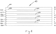
- Figs. 3 and 4 illustrate an exemplary layup of the laminate 40. However, it should be understood that the number of plies, the orientation of the plies, as well as the number and location of the insulating layers 60 are only an example; the invention is not limited to the layup illustrated in this exemplary laminate.
- the layers do not need to be laid up in pairs. For instance, as shown in Fig. 4 the layers are laid up in pairs. However, in Fig. 3 the top and bottom layers 52, 58 are laid up as single layers, while the six plies between the top and bottom layers are laid up in pairs.
- the insulation layers 60 are selectively inserted between structural layers of the laminate. Although insulation layers may be inserted between each layer of the laminate, in the present instance, the insulation layers are inserted between less than all the structural layers. In particular, the insulation layers are inserted between layers having a select characteristic. For example, in the present instance, the select characteristic is a change in fiber direction. An insulation layer 60 is inserted between adjacent layers having different fiber angle. Accordingly, in the lay-up described above, the insulating layers 60 are interposed between the pairs of structural layers but not with in the layers in the pair. More specifically, referring to Figs. 3-4 , the first insulating layer 60a is positioned between layer 50 (in Fig. 3 ) or 50b (in Fig.
- the interface between layer 50/50b and layer 52a is an interface in which the fibers in adjacent layers are transverse one another (i.e. the fiber angle changes from 90° to 0°).
- the second insulating layer 60b is positioned between layer 52b and layer 54a because the fiber angle changes from 0° to 45°.
- the third insulating layer 60c is positioned between the third and fourth pairs (i.e. the interface of layers 54b and 56a) where the fiber angle changes from 45° to 0°.
- the fourth insulating layer 60d is position between the fourth and fifth pairs (i.e. the interface of layers 56b and 58a or layer 58 in Fig. 3 ) where the fiber angle changes from 0° to 90°.
- the laminate 40 may be formed using a variety of processes. The details of a method of forming the laminate 40 from a plurality of reinforced thermoplastic layers will now be described. Additionally, the method of forming an aerostructure using the laminate will also be described.
- a plurality of layers of carbon fiber reinforced thermoplastic tape are laid over top of one another to form a plurality of plies that are structural layers.
- the fiber orientation in the plies may be varied and insulating plies may be positioned in the interface of plies having transverse fiber orientations.
- the layers may be formed of ten structural plies and 4 insulating layers oriented at 90°, 90°, Ins, 0°, 0°, Ins, 45°, 45°, Ins, 0°, 0°, Ins, 90°, 90° (wherein "Ins” refers to an insulating layer).
- the insulating layers are formed of one or more insulating elements forming a pattern.
- the structural layers and insulating layers are consolidated to form a laminate by heating the assembled plies under pressure.
- the assembly may be heated up to a temperature above the melting temperature.
- the assembled layers are heated to approximately 725° under a pressure of approximately 206843 Pa (30 psi).
- the pressure is raised to approximately 689476 Pa (100 psi) and the assembly is maintained at the elevated temperature for an extended time, such as approximately 30 minutes.
- the pressure is then removed and the consolidated laminate is cooled to ambient temperature.
- the laminate may be connected with one or more separate elements to form as structure.
- One exemplary structure is an aerostructure. More specifically, the laminate is configured so that the laminate can be welded to a separate structure. Further still, the laminate is constructed so that the heat generated during the welding process is isolated to a select ply or plies of the laminate. Additionally, the heat generated may be isolated to select areas of the select ply. The process of welding the laminate with a separate element will now be described in greater detail.
- the laminate is formed with one or more insulating layers.
- the insulating layer(s) may be formed according to a pattern.
- the pattern may be similar to the contact area of the separate element or assembly that is to be welded to the laminate.
- the insulating layer may form a grid that is shaped similarly to the grid formed by the ribs 30, 35 and spars 20, 25 of the support structure 15.
- the method includes the step of aligning the pattern of the insulating layer(s) with the grid formed by the ribs and spars.
- the upper surface of the support structure comprises one or more connecting elements for welding the support structure to the laminate.
- the ribs 30, 35 and spars 20, 25 may be formed so that the upper surface 22, 27, 32, 37 form connecting elements.
- the connecting elements may be separate elements that are fixedly connected with the ribs and spars.
- the connecting element is a ply of carbon fiber reinforced thermoplastic material similar to the material forming the structural plies of the laminate 40.
- the connecting element is designated 39 and is illustrated as a laminate fixedly connected to the top of the flange 37 of intermediate rib 35.
- the connecting element may be an integral part of the underlying structure.
- the ribs 35 may be formed so that the flange 37 is formed of carbon fiber reinforced thermoplastic material that would operate as the connecting element.
- the connecting element may be a separate element that is mechanically fastened, such as by a clip or a fastener.
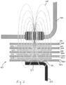
- the weld head 100 heats the bottom layer and the connecting element by electromagnetic induction, through heat generated by eddy currents.
- the weld head includes an electronic oscillator that passes a high-frequency alternating current through an electromagnet. The rapidly alternating magnetic field then penetrates the laminate and connecting element to generate the eddy currents which in turn heat the bottom layer and connecting element.
- the weld head induces an electromagnetic field through the laminate and the connecting elements, so that the adjacent layers having transverse carbon fibers heat up in response to the electromagnetic field.
- layers that are separated by the insulating layers 60 do not heat above the melting temperature in response to the electromagnetic field.
- the electromagnetic field produced by the weld head is sufficient to heat the bottom layer 58a and the connecting element 39 above the melting temperature of the thermoplastic matrix material for the bottom layer and the connecting element. After raising the bottom layer and the connecting element above the melting layer while applying pressure, the bottom layer fuses with the connecting element to weld the two items together. Additionally, as noted above, the insulating layers 60 insulate the adjacent layers from the inductive heat caused by the weld head.
- the electromagnetic field may extend beyond the edges of the insulating elements of the insulating layer. Accordingly, the electromagnetic field may induce some heating in the structural plies. However, the induced heating will be substantially lower than the heating induced between the non-insulated layers (i.e. 58b and 39) and will be substantially below the melting point of the structural layers. In this way, the insulating layers limit the heating of the structural layers to below the melting temperature while allowing the bottom layer and the connecting element to be heated above the melting temperature. Therefore, although the insulating layers do not necessarily prevent all heating of the layers adjacent the insulating layers, for purposes of this methodology, the insulating layers prevent the heating of the layers if the insulating layers limit the heating of the layers to substantially below the melting point.
- the weld head 100 is shown as inducing an electromagnetic field through the laminate to weld the laminate to the rib 35.
- the method includes the step of controlling the travel of the weld head so that the weld head is conveyed over the laminate to weld a plurality of points of the laminate to the support structure 15.
- the method may include the step of controlling the position of the weld head to follow the pattern formed by the insulating layer. In this way, the weld head welds the laminate to the support structure along the areas corresponding with the pattern formed by the insulating layer 60.
- the laminate is described as a flat panel laminate.
- the invention is not limited to flat panel structures.
- the laminate may be used in a variety of structures in a variety of fields and may have particular application in the field of aerospace to provide a variety of components, including, but not limited to airframes, nacelles and airfoils, such as wings, elevators etc.
- the laminate 40 described above may be formed into a curved structure and connected with a separate element or structure.
Landscapes
- Engineering & Computer Science (AREA)
- Mechanical Engineering (AREA)
- Aviation & Aerospace Engineering (AREA)
- Textile Engineering (AREA)
- Manufacturing & Machinery (AREA)
- Transportation (AREA)
- Physics & Mathematics (AREA)
- Thermal Sciences (AREA)
- Laminated Bodies (AREA)
- Lining Or Joining Of Plastics Or The Like (AREA)
- Moulding By Coating Moulds (AREA)
Claims (7)
- Luftfahrzeug-Verbundstruktur (10) umfassend:eine Vielzahl von längsgestreckten Holmen (20, 25), von denen jeder ein oberes Element umfasst, das eine Schicht von mit unidirektionalen oder gewebten Kohlenstofffasern verstärktem thermoplastischen Material aufweist, das eine Schweißzone bildet; undeine Vielzahl von langgestreckten Rippen (30, 35), die mit der Vielzahl von Holmen (20, 25) verbunden sind, um ein Gitter zu bilden, wobei jede Rippe ein oberes Element umfasst, das eine Schicht von mit unidirektionalen oder gewebten Kohlenstofffasern verstärktem thermoplastischen Material aufweist, das eine Schweißzone bildet;eine Verbundstoffhaut, die mit dem Gitter von Holmen (20, 25) und Rippen (30, 35) verbunden ist, umfassend:eine erste Lage aus mit unidirektionalen Kohlenstofffasern verstärktem thermoplastischen Material, wobei die Kohlenstofffasern in einer ersten Richtung orientiert sind;eine zweite Lage aus mit unidirektionalen Kohlenstofffasern verstärktem thermoplastischen Material, wobei die Kohlenstofffasern in der ersten Richtung orientiert sind und die erste Lage über der zweiten Lage liegt und direkt damit verbunden ist;eine dritte Lage aus mit unidirektionalen Kohlenstofffasern verstärktem thermoplastischen Material, wobei die Kohlenstofffasern in einer zweiten Richtung quer zu der ersten Richtung orientiert sind;eine vierte Lage aus mit unidirektionalen Kohlenstofffasern verstärktem thermoplastischen Material, wobei die Kohlenstofffasern in der zweiten Richtung orientiert sind und die dritte Lage über der vierten Lage liegt und direkt damit verbunden ist;eine fünfte Lage aus mit unidirektionalen Kohlenstofffasern verstärktem thermoplastischen Material, wobei die Kohlenstofffasern quer zu den Kohlenstofffasern in den oberen Elementen der Holme (20, 25) und der Rippen (30, 35) orientiert sind;eine Vielzahl von langgestreckten isolierenden Elementen, die aus elektrisch isolierendem Material gebildet sind, wobei die isolierenden Elemente jeweils eine Länge und eine Breite aufweisen und wenigstens eine Vielzahl der isolierenden Elemente eine Länge aufweist, die wesentlich größer als die Breite ist; und wobei die isolierenden Elemente ein Gitter bilden, das im Wesentlichen ähnlich wie das von den Rippen (30, 35) und Holmen (20, 25) gebildete Gitter gestaltet ist, so dass die isolierenden Elemente über den oberen Elementen der Holme (20, 25) und Rippen (30, 35) liegen, wobei das Gitter von isolierenden Elementen zwischen der zweiten Schicht und der dritten Schicht angeordnet ist.
- Luftfahrzeugstruktur (10) gemäß Anspruch 1, wobei die Verbundstoffhaut zusätzliche Schichten von kohlenstofffaserverstärktem thermoplastischen Material umfasst und wobei das Gitter von isolierenden Elementen ein erstes Gitter ist und die Vielzahl von isolierenden Elementen ein zweites Gitter bildet, das im Wesentlichen ähnlich wie das erste Gitter von isolierenden Elementen gestaltet ist, wobei das zweite Gitter zwischen den zusätzlichen Schichten von kohlenstofffaserverstärktem thermoplastischen Material angeordnet ist, so dass das zweite Gitter mit dem ersten Gitter ausgerichtet ist.
- Luftfahrzeugstruktur (10) gemäß Anspruch 2, wobei jedes isolierende Element Glasfasern umfasst, die in einer Matrix von thermoplastischem Material eingebettet sind, und die Luftfahrzeugstruktur (10) eine zweite Verbundstoffhaut umfasst, die mit dem Gitter von Rippen (30, 35) und Holmen (20, 25) verbunden ist.
- Luftfahrzeugstruktur (10) gemäß Anspruch 3, wobei jeder Holm (20, 25) und jede Rippe (30, 35) ein unteres Element umfasst, das eine Schicht von mit unidirektionalen Kohlenstofffasern verstärktem thermoplastischen Material aufweist, das eine untere Schweißzone bildet.
- Luftfahrzeugstruktur (10) gemäß Anspruch 4, wobei die zweite Haut mit den unteren Elementen der Rippen (30, 35) und Holme (20, 25) verbunden ist.
- Luftfahrzeugstruktur (10) gemäß Anspruch 1, wobei die isolierenden Elemente so gestaltet sind, dass Thermoplast der ersten bis vierten Lage unter einer Schmelztemperatur gehalten wird, wenn die fünfte Lage durch einen Induktionsschweißkopf auf eine Temperatur über der Schmelztemperatur erhitzt wird.
- Luftfahrzeugstruktur (10) gemäß Anspruch 1, wobei der Thermopast der fünften Schicht eine Schmelztemperatur aufweist und die isolierenden Elemente dafür gestaltet sind, Erhitzen der zweiten und dritten Schicht auf über die Schmelztemperatur zu verhindern, wenn das fünfte Laminat gegenüber einem elektromagnetischen Feld exponiert wird, das ausreicht, um einen Teil des fünften Laminats auf über die Schmelztemperatur zu heben.
Priority Applications (1)
| Application Number | Priority Date | Filing Date | Title |
|---|---|---|---|
| EP24185968.5A EP4458685A3 (de) | 2018-05-03 | 2019-05-03 | Thermoplastische flugzeugstruktur mit lokalisierter lagenisolierung und verfahren zur herstellung einer flugzeugstruktur |
Applications Claiming Priority (2)
| Application Number | Priority Date | Filing Date | Title |
|---|---|---|---|
| US201862666193P | 2018-05-03 | 2018-05-03 | |
| PCT/US2019/030611 WO2019213529A1 (en) | 2018-05-03 | 2019-05-03 | Thermoplastic aerostructure with localized ply isolation and method for forming aerostructure |
Related Child Applications (1)
| Application Number | Title | Priority Date | Filing Date |
|---|---|---|---|
| EP24185968.5A Division EP4458685A3 (de) | 2018-05-03 | 2019-05-03 | Thermoplastische flugzeugstruktur mit lokalisierter lagenisolierung und verfahren zur herstellung einer flugzeugstruktur |
Publications (3)
| Publication Number | Publication Date |
|---|---|
| EP3787965A1 EP3787965A1 (de) | 2021-03-10 |
| EP3787965A4 EP3787965A4 (de) | 2022-05-04 |
| EP3787965B1 true EP3787965B1 (de) | 2024-07-03 |
Family
ID=68241806
Family Applications (2)
| Application Number | Title | Priority Date | Filing Date |
|---|---|---|---|
| EP24185968.5A Pending EP4458685A3 (de) | 2018-05-03 | 2019-05-03 | Thermoplastische flugzeugstruktur mit lokalisierter lagenisolierung und verfahren zur herstellung einer flugzeugstruktur |
| EP19796952.0A Active EP3787965B1 (de) | 2018-05-03 | 2019-05-03 | Thermoplastische flugzeugstruktur mit lokalisierter lagenisolierung und verfahren zur herstellung einer flugzeugstruktur |
Family Applications Before (1)
| Application Number | Title | Priority Date | Filing Date |
|---|---|---|---|
| EP24185968.5A Pending EP4458685A3 (de) | 2018-05-03 | 2019-05-03 | Thermoplastische flugzeugstruktur mit lokalisierter lagenisolierung und verfahren zur herstellung einer flugzeugstruktur |
Country Status (7)
| Country | Link |
|---|---|
| US (3) | US10449749B1 (de) |
| EP (2) | EP4458685A3 (de) |
| JP (4) | JP6986194B2 (de) |
| KR (3) | KR102827647B1 (de) |
| BR (1) | BR122023020216A2 (de) |
| ES (1) | ES2989486T3 (de) |
| WO (1) | WO2019213529A1 (de) |
Families Citing this family (11)
| Publication number | Priority date | Publication date | Assignee | Title |
|---|---|---|---|---|
| EP3784488B1 (de) | 2018-04-24 | 2024-08-21 | Qarbon Aerospace (Foundation), LLC | Flugzeugstruktur aus verbundwerkstoff mit integriertem heizelement |
| WO2019213529A1 (en) | 2018-05-03 | 2019-11-07 | Triumph Aerostructures, Llc. | Thermoplastic aerostructure with localized ply isolation and method for forming aerostructure |
| US20200086583A1 (en) * | 2018-09-13 | 2020-03-19 | University Of South Carolina | Welding And Consolidation Of Thermoplastic Composites Using Vacuum Bagging, Air Cooling And Induction |
| NL2025473B1 (en) * | 2020-04-30 | 2021-11-18 | Kok & Van Engelen Composite Structures B V | Fiber-reinforced composite laminate for use in electromagnetic welding and method of electromagnetic welding of molded parts of said laminates |
| CN114905131A (zh) * | 2021-01-29 | 2022-08-16 | 波音公司 | 用于控制感应焊接的方法和设备 |
| CN113602474B (zh) * | 2021-08-16 | 2023-09-29 | 中国商用飞机有限责任公司北京民用飞机技术研究中心 | 一种热塑性复合材料机翼油箱盒段及其制造方法 |
| EP4186783B1 (de) * | 2021-11-24 | 2025-01-08 | Airbus Operations, S.L.U. | Verfahren zur herstellung einer steuerfläche eines flugzeugs |
| US11865791B2 (en) | 2021-12-30 | 2024-01-09 | Rohr, Inc. | Induction welding with an electromagnetic field concentrator |
| US20240165909A1 (en) * | 2022-07-15 | 2024-05-23 | Joby Aero, Inc. | Laminate Material |
| US20240109644A1 (en) * | 2022-09-29 | 2024-04-04 | Rohr, Inc. | Thermoplastic interlocking grid structure for flight control surfaces |
| WO2024256037A1 (de) * | 2023-06-12 | 2024-12-19 | Enerkite Gmbh | Aerodynamische hohlkammer-strukturen |
Family Cites Families (51)
| Publication number | Priority date | Publication date | Assignee | Title |
|---|---|---|---|---|
| US3768760A (en) * | 1970-10-30 | 1973-10-30 | Hercules Inc | Graphite fiber composite covering employing multi-directional |
| US4177376A (en) * | 1974-09-27 | 1979-12-04 | Raychem Corporation | Layered self-regulating heating article |
| GB8618727D0 (en) | 1986-07-31 | 1986-09-10 | Wiggins Teape Group Ltd | Thermoplastic sheets |
| GB8704852D0 (en) | 1987-03-02 | 1987-04-08 | Welding Inst | Bonding thermoplastic layers |
| IT1215985B (it) | 1988-03-04 | 1990-02-22 | Elca Srl | Procedimento elettrochimico per la realizzazione di rivestimenti di cromo e metalli simili mediante corrente pulsante ad inversione periodica della polarita' |
| US4957577A (en) * | 1988-04-04 | 1990-09-18 | Plascore, Inc. | Method for making welded honeycomb core |
| US4990213A (en) | 1988-11-29 | 1991-02-05 | Northrop Corporation | Automated tape laminator head for thermoplastic matrix composite material |
| US5059377A (en) * | 1989-07-21 | 1991-10-22 | Aerotrans Corporation | Method for forming a composite structure |
| US5240542A (en) | 1990-09-06 | 1993-08-31 | The Board Of Trustees Of The Leland Stanford Junior University | Joining of composite materials by induction heating |
| US7126096B1 (en) * | 1991-04-05 | 2006-10-24 | Th Boeing Company | Resistance welding of thermoplastics in aerospace structure |
| EP0608240B1 (de) | 1991-07-12 | 1998-11-11 | Hexcel Corporation | Verfahren und vorrichtung zur herstellung von verschweissten thermoplastischen wabenstrukturen |
| US5359911A (en) | 1993-06-30 | 1994-11-01 | U.S. Composites Corp. | Lightweight self-insulating composite tool |
| TW253870B (en) | 1994-07-11 | 1995-08-11 | Newell Operating Co | Cellular panel and method and apparatus for making the same |
| US5662293A (en) | 1995-05-05 | 1997-09-02 | Hower; R. Thomas | Polyimide foam-containing radomes |
| AU6263796A (en) | 1995-06-07 | 1996-12-30 | Boeing Company, The | Hybrid metal webbed composite beam |
| US5700347A (en) | 1996-01-11 | 1997-12-23 | The Boeing Company | Thermoplastic multi-tape application head |
| FR2744872B1 (fr) | 1996-02-08 | 1998-04-10 | Eurocopter France | Dispositif de chauffage d'un profil aerodynamique |
| US6237874B1 (en) | 1997-09-22 | 2001-05-29 | Northcoast Technologies | Zoned aircraft de-icing system and method |
| US5934617A (en) | 1997-09-22 | 1999-08-10 | Northcoast Technologies | De-ice and anti-ice system and method for aircraft surfaces |
| US6279856B1 (en) | 1997-09-22 | 2001-08-28 | Northcoast Technologies | Aircraft de-icing system |
| US6284089B1 (en) * | 1997-12-23 | 2001-09-04 | The Boeing Company | Thermoplastic seam welds |
| US6611659B2 (en) | 1999-04-24 | 2003-08-26 | Airbus Deutschland Gmbh | Electrically heated aircraft composite floor panel |
| DE19918736C2 (de) * | 1999-04-24 | 2002-12-05 | Airbus Gmbh | Plattenbauteil, insbesondere für eine Fußbodenplatte in einem Flugzeug |
| US6799619B2 (en) | 2002-02-06 | 2004-10-05 | The Boeing Company | Composite material collation machine and associated method for high rate collation of composite materials |
| US7243055B2 (en) | 2004-01-28 | 2007-07-10 | The Boeing Company | Composite stacking sequence optimization for multi-zoned composites |
| US7281318B2 (en) * | 2004-05-19 | 2007-10-16 | The Boeing Company | Method of manufacturing a composite structural member having an integrated electrical circuit |
| MX2007014660A (es) | 2005-05-27 | 2008-03-07 | Bell Helicopter Textron Inc | Calentador hibrido conductor/resistente compuesto capaz de deformacion para dispositivo termico anti-hielo. |
| GB0615104D0 (en) * | 2006-07-28 | 2006-09-06 | Airbus Uk Ltd | Aircraft wing box and manufacture thereof |
| GB2453769B (en) | 2007-10-18 | 2012-09-05 | Gkn Aerospace Services Ltd | An aircraft leading edge thermoplastic heating mat |
| DE102008013759B4 (de) * | 2008-03-12 | 2012-12-13 | Airbus Operations Gmbh | Verfahren zur Herstellung eines integralen Faserverbundbauteils sowie Kernform zur Durchführung des Verfahrens |
| DE102008020564B4 (de) | 2008-04-24 | 2013-10-02 | Airbus Operations Gmbh | Tapelegevorrichtung sowie Verfahren zum Aufbau eines Laminats |
| CA2732694C (en) | 2008-08-06 | 2018-03-13 | Lubrizol Advanced Materials, Inc. | Films and articles made with thermoplastic block copolymers |
| US8158245B2 (en) | 2009-09-24 | 2012-04-17 | Cytec Technology Corp. | Thermoplastic composites and methods of making and using same |
| EP2523854B1 (de) | 2010-01-14 | 2015-12-16 | Saab AB | Multifunktionsenteisungs-/eisschutzsystem |
| GB2477340B (en) | 2010-01-29 | 2011-12-07 | Gkn Aerospace Services Ltd | Electrothermal heater mat |
| GB2477339B (en) | 2010-01-29 | 2011-12-07 | Gkn Aerospace Services Ltd | Electrothermal heater mat |
| GB201006257D0 (en) | 2010-04-15 | 2010-06-02 | Airbus Operations Ltd | Composite structure |
| EP3575218B1 (de) | 2010-12-31 | 2021-08-11 | Battelle Memorial Institute | Antenne mit schicht aus kohlenstoff-nanoröhrchen |
| US9227732B2 (en) | 2011-05-23 | 2016-01-05 | Ultra Electronics Ice, Inc. | Electro-thermal ice protection system and method with serial load leveling |
| KR101532194B1 (ko) | 2012-07-25 | 2015-07-15 | 도레이 카부시키가이샤 | 프리프레그 및 탄소 섬유 강화 복합 재료 |
| FR2996525B1 (fr) | 2012-10-09 | 2014-11-28 | Aircelle Sa | Element constitutif d’une nacelle a protection contre le givre amelioree |
| GB2513652A (en) | 2013-05-03 | 2014-11-05 | Rolls Royce Plc | Vehicle composite structure |
| EP2910365B1 (de) * | 2014-02-21 | 2017-04-26 | Airbus Operations GmbH | Verbundstrukturelement und Torsionskasten |
| US10368401B2 (en) | 2014-06-03 | 2019-07-30 | Aurora Flight Sciences Corporation | Multi-functional composite structures |
| US10099434B2 (en) | 2014-09-16 | 2018-10-16 | General Electric Company | Composite airfoil structures |
| US10040537B2 (en) * | 2015-01-15 | 2018-08-07 | The Boeing Company | Laminate composite wing structures |
| US9840043B2 (en) | 2015-02-17 | 2017-12-12 | Bell Helicopter Textron Inc. | Manufacture of thermoplastic core |
| US20170238367A1 (en) | 2016-02-15 | 2017-08-17 | General Electric Company | Integrated Conductive Foam Core for Composite Processing |
| CN107386752A (zh) | 2017-07-19 | 2017-11-24 | 天津工业大学 | 一种具有防冰除冰功能的纤维增强复合材料塔杆 |
| EP3784488B1 (de) | 2018-04-24 | 2024-08-21 | Qarbon Aerospace (Foundation), LLC | Flugzeugstruktur aus verbundwerkstoff mit integriertem heizelement |
| WO2019213529A1 (en) | 2018-05-03 | 2019-11-07 | Triumph Aerostructures, Llc. | Thermoplastic aerostructure with localized ply isolation and method for forming aerostructure |
-
2019
- 2019-05-03 WO PCT/US2019/030611 patent/WO2019213529A1/en not_active Ceased
- 2019-05-03 US US16/402,780 patent/US10449749B1/en not_active Expired - Fee Related
- 2019-05-03 BR BR122023020216-3A patent/BR122023020216A2/pt unknown
- 2019-05-03 KR KR1020237005132A patent/KR102827647B1/ko active Active
- 2019-05-03 EP EP24185968.5A patent/EP4458685A3/de active Pending
- 2019-05-03 ES ES19796952T patent/ES2989486T3/es active Active
- 2019-05-03 KR KR1020227002210A patent/KR102500752B1/ko active Active
- 2019-05-03 EP EP19796952.0A patent/EP3787965B1/de active Active
- 2019-05-03 KR KR1020207034912A patent/KR102356284B1/ko active Active
- 2019-05-03 JP JP2020573564A patent/JP6986194B2/ja active Active
- 2019-08-30 US US16/557,107 patent/US11440288B2/en active Active
-
2021
- 2021-10-25 JP JP2021173927A patent/JP7268112B2/ja active Active
-
2022
- 2022-08-03 US US17/879,845 patent/US20230166478A1/en not_active Abandoned
-
2023
- 2023-04-20 JP JP2023068907A patent/JP7662700B2/ja active Active
-
2025
- 2025-04-03 JP JP2025061522A patent/JP2025114549A/ja active Pending
Also Published As
| Publication number | Publication date |
|---|---|
| BR112020022321A2 (pt) | 2021-02-23 |
| JP7268112B2 (ja) | 2023-05-02 |
| BR122023020216A2 (pt) | 2024-01-16 |
| KR20210028151A (ko) | 2021-03-11 |
| EP3787965A1 (de) | 2021-03-10 |
| ES2989486T3 (es) | 2024-11-26 |
| EP3787965A4 (de) | 2022-05-04 |
| EP4458685A2 (de) | 2024-11-06 |
| JP2021517096A (ja) | 2021-07-15 |
| US20230166478A1 (en) | 2023-06-01 |
| JP7662700B2 (ja) | 2025-04-15 |
| KR102827647B1 (ko) | 2025-07-01 |
| KR102500752B1 (ko) | 2023-02-17 |
| KR20230028573A (ko) | 2023-02-28 |
| WO2019213529A1 (en) | 2019-11-07 |
| US20190337261A1 (en) | 2019-11-07 |
| US11440288B2 (en) | 2022-09-13 |
| JP2025114549A (ja) | 2025-08-05 |
| JP6986194B2 (ja) | 2021-12-22 |
| US20200001569A1 (en) | 2020-01-02 |
| EP4458685A3 (de) | 2025-01-01 |
| JP2022025099A (ja) | 2022-02-09 |
| KR20220013954A (ko) | 2022-02-04 |
| JP2023103253A (ja) | 2023-07-26 |
| KR102356284B1 (ko) | 2022-02-09 |
| US10449749B1 (en) | 2019-10-22 |
Similar Documents
| Publication | Publication Date | Title |
|---|---|---|
| EP3787965B1 (de) | Thermoplastische flugzeugstruktur mit lokalisierter lagenisolierung und verfahren zur herstellung einer flugzeugstruktur | |
| US11952131B2 (en) | Composite aerostructure with integrated heating element | |
| KR102308583B1 (ko) | 열가소성 재료의 부품들을 용접하기 위한 방법 | |
| US5760379A (en) | Monitoring the bond line temperature in thermoplastic welds | |
| EP3138769B1 (de) | Radiusfüllstoffhaltige vertikallagenstapel und dünnlagen | |
| EP2739466B1 (de) | Molybdän-verbundhybrid- laminate und verfahren dafür | |
| US5756973A (en) | Barbed susceptor for improviing pulloff strength in welded thermoplastic composite structures | |
| US11939038B2 (en) | Fuselage structure of an aircraft and method for manufacturing the same | |
| CN114206606A (zh) | 用于接合纤维增强聚合物和金属结构的金属网状物过渡件 | |
| US20160136879A1 (en) | Susceptor Welding Tape |
Legal Events
| Date | Code | Title | Description |
|---|---|---|---|
| STAA | Information on the status of an ep patent application or granted ep patent |
Free format text: STATUS: THE INTERNATIONAL PUBLICATION HAS BEEN MADE |
|
| PUAI | Public reference made under article 153(3) epc to a published international application that has entered the european phase |
Free format text: ORIGINAL CODE: 0009012 |
|
| STAA | Information on the status of an ep patent application or granted ep patent |
Free format text: STATUS: REQUEST FOR EXAMINATION WAS MADE |
|
| 17P | Request for examination filed |
Effective date: 20201120 |
|
| AK | Designated contracting states |
Kind code of ref document: A1 Designated state(s): AL AT BE BG CH CY CZ DE DK EE ES FI FR GB GR HR HU IE IS IT LI LT LU LV MC MK MT NL NO PL PT RO RS SE SI SK SM TR |
|
| AX | Request for extension of the european patent |
Extension state: BA ME |
|
| DAV | Request for validation of the european patent (deleted) | ||
| DAX | Request for extension of the european patent (deleted) | ||
| RAP1 | Party data changed (applicant data changed or rights of an application transferred) |
Owner name: QARBON AEROSPACE (FOUNDATION), LLC |
|
| RIC1 | Information provided on ipc code assigned before grant |
Ipc: B64C 3/26 20060101ALI20211220BHEP Ipc: B64C 1/12 20060101ALI20211220BHEP Ipc: B29C 65/36 20060101ALI20211220BHEP Ipc: B64C 3/20 20060101AFI20211220BHEP |
|
| A4 | Supplementary search report drawn up and despatched |
Effective date: 20220405 |
|
| RIC1 | Information provided on ipc code assigned before grant |
Ipc: B64C 3/26 20060101ALI20220330BHEP Ipc: B64C 1/12 20060101ALI20220330BHEP Ipc: B29C 65/36 20060101ALI20220330BHEP Ipc: B64C 3/20 20060101AFI20220330BHEP |
|
| REG | Reference to a national code |
Ref country code: DE Ref legal event code: R079 Free format text: PREVIOUS MAIN CLASS: B64C0003200000 Ipc: B32B0003080000 Ref document number: 602019054668 Country of ref document: DE |
|
| GRAP | Despatch of communication of intention to grant a patent |
Free format text: ORIGINAL CODE: EPIDOSNIGR1 |
|
| STAA | Information on the status of an ep patent application or granted ep patent |
Free format text: STATUS: GRANT OF PATENT IS INTENDED |
|
| RIC1 | Information provided on ipc code assigned before grant |
Ipc: B64F 5/10 20170101ALI20240117BHEP Ipc: B64C 3/26 20060101ALI20240117BHEP Ipc: B64C 3/18 20060101ALI20240117BHEP Ipc: B32B 37/06 20060101ALI20240117BHEP Ipc: B32B 7/08 20190101ALI20240117BHEP Ipc: B32B 5/26 20060101ALI20240117BHEP Ipc: B32B 5/12 20060101ALI20240117BHEP Ipc: B32B 5/02 20060101ALI20240117BHEP Ipc: B32B 3/08 20060101AFI20240117BHEP |
|
| INTG | Intention to grant announced |
Effective date: 20240131 |
|
| GRAS | Grant fee paid |
Free format text: ORIGINAL CODE: EPIDOSNIGR3 |
|
| GRAA | (expected) grant |
Free format text: ORIGINAL CODE: 0009210 |
|
| STAA | Information on the status of an ep patent application or granted ep patent |
Free format text: STATUS: THE PATENT HAS BEEN GRANTED |
|
| AK | Designated contracting states |
Kind code of ref document: B1 Designated state(s): AL AT BE BG CH CY CZ DE DK EE ES FI FR GB GR HR HU IE IS IT LI LT LU LV MC MK MT NL NO PL PT RO RS SE SI SK SM TR |
|
| REG | Reference to a national code |
Ref country code: CH Ref legal event code: EP |
|
| REG | Reference to a national code |
Ref country code: DE Ref legal event code: R096 Ref document number: 602019054668 Country of ref document: DE |
|
| P01 | Opt-out of the competence of the unified patent court (upc) registered |
Free format text: CASE NUMBER: APP_44395/2024 Effective date: 20240730 |
|
| REG | Reference to a national code |
Ref country code: LT Ref legal event code: MG9D |
|
| REG | Reference to a national code |
Ref country code: NL Ref legal event code: MP Effective date: 20240703 |
|
| REG | Reference to a national code |
Ref country code: ES Ref legal event code: FG2A Ref document number: 2989486 Country of ref document: ES Kind code of ref document: T3 Effective date: 20241126 |
|
| PG25 | Lapsed in a contracting state [announced via postgrant information from national office to epo] |
Ref country code: PT Free format text: LAPSE BECAUSE OF FAILURE TO SUBMIT A TRANSLATION OF THE DESCRIPTION OR TO PAY THE FEE WITHIN THE PRESCRIBED TIME-LIMIT Effective date: 20241104 |
|
| REG | Reference to a national code |
Ref country code: AT Ref legal event code: MK05 Ref document number: 1699423 Country of ref document: AT Kind code of ref document: T Effective date: 20240703 |
|
| PG25 | Lapsed in a contracting state [announced via postgrant information from national office to epo] |
Ref country code: NL Free format text: LAPSE BECAUSE OF FAILURE TO SUBMIT A TRANSLATION OF THE DESCRIPTION OR TO PAY THE FEE WITHIN THE PRESCRIBED TIME-LIMIT Effective date: 20240703 |
|
| PG25 | Lapsed in a contracting state [announced via postgrant information from national office to epo] |
Ref country code: PT Free format text: LAPSE BECAUSE OF FAILURE TO SUBMIT A TRANSLATION OF THE DESCRIPTION OR TO PAY THE FEE WITHIN THE PRESCRIBED TIME-LIMIT Effective date: 20241104 Ref country code: NL Free format text: LAPSE BECAUSE OF FAILURE TO SUBMIT A TRANSLATION OF THE DESCRIPTION OR TO PAY THE FEE WITHIN THE PRESCRIBED TIME-LIMIT Effective date: 20240703 |
|
| PG25 | Lapsed in a contracting state [announced via postgrant information from national office to epo] |
Ref country code: NO Free format text: LAPSE BECAUSE OF FAILURE TO SUBMIT A TRANSLATION OF THE DESCRIPTION OR TO PAY THE FEE WITHIN THE PRESCRIBED TIME-LIMIT Effective date: 20241003 |
|
| PG25 | Lapsed in a contracting state [announced via postgrant information from national office to epo] |
Ref country code: GR Free format text: LAPSE BECAUSE OF FAILURE TO SUBMIT A TRANSLATION OF THE DESCRIPTION OR TO PAY THE FEE WITHIN THE PRESCRIBED TIME-LIMIT Effective date: 20241004 Ref country code: FI Free format text: LAPSE BECAUSE OF FAILURE TO SUBMIT A TRANSLATION OF THE DESCRIPTION OR TO PAY THE FEE WITHIN THE PRESCRIBED TIME-LIMIT Effective date: 20240703 Ref country code: PL Free format text: LAPSE BECAUSE OF FAILURE TO SUBMIT A TRANSLATION OF THE DESCRIPTION OR TO PAY THE FEE WITHIN THE PRESCRIBED TIME-LIMIT Effective date: 20240703 |
|
| PG25 | Lapsed in a contracting state [announced via postgrant information from national office to epo] |
Ref country code: BG Free format text: LAPSE BECAUSE OF FAILURE TO SUBMIT A TRANSLATION OF THE DESCRIPTION OR TO PAY THE FEE WITHIN THE PRESCRIBED TIME-LIMIT Effective date: 20240703 |
|
| PG25 | Lapsed in a contracting state [announced via postgrant information from national office to epo] |
Ref country code: LV Free format text: LAPSE BECAUSE OF FAILURE TO SUBMIT A TRANSLATION OF THE DESCRIPTION OR TO PAY THE FEE WITHIN THE PRESCRIBED TIME-LIMIT Effective date: 20240703 |
|
| PG25 | Lapsed in a contracting state [announced via postgrant information from national office to epo] |
Ref country code: AT Free format text: LAPSE BECAUSE OF FAILURE TO SUBMIT A TRANSLATION OF THE DESCRIPTION OR TO PAY THE FEE WITHIN THE PRESCRIBED TIME-LIMIT Effective date: 20240703 Ref country code: IS Free format text: LAPSE BECAUSE OF FAILURE TO SUBMIT A TRANSLATION OF THE DESCRIPTION OR TO PAY THE FEE WITHIN THE PRESCRIBED TIME-LIMIT Effective date: 20241103 |
|
| PG25 | Lapsed in a contracting state [announced via postgrant information from national office to epo] |
Ref country code: CZ Free format text: LAPSE BECAUSE OF FAILURE TO SUBMIT A TRANSLATION OF THE DESCRIPTION OR TO PAY THE FEE WITHIN THE PRESCRIBED TIME-LIMIT Effective date: 20240703 Ref country code: HR Free format text: LAPSE BECAUSE OF FAILURE TO SUBMIT A TRANSLATION OF THE DESCRIPTION OR TO PAY THE FEE WITHIN THE PRESCRIBED TIME-LIMIT Effective date: 20240703 |
|
| PG25 | Lapsed in a contracting state [announced via postgrant information from national office to epo] |
Ref country code: RS Free format text: LAPSE BECAUSE OF FAILURE TO SUBMIT A TRANSLATION OF THE DESCRIPTION OR TO PAY THE FEE WITHIN THE PRESCRIBED TIME-LIMIT Effective date: 20241003 |
|
| PG25 | Lapsed in a contracting state [announced via postgrant information from national office to epo] |
Ref country code: RS Free format text: LAPSE BECAUSE OF FAILURE TO SUBMIT A TRANSLATION OF THE DESCRIPTION OR TO PAY THE FEE WITHIN THE PRESCRIBED TIME-LIMIT Effective date: 20241003 Ref country code: PL Free format text: LAPSE BECAUSE OF FAILURE TO SUBMIT A TRANSLATION OF THE DESCRIPTION OR TO PAY THE FEE WITHIN THE PRESCRIBED TIME-LIMIT Effective date: 20240703 Ref country code: NO Free format text: LAPSE BECAUSE OF FAILURE TO SUBMIT A TRANSLATION OF THE DESCRIPTION OR TO PAY THE FEE WITHIN THE PRESCRIBED TIME-LIMIT Effective date: 20241003 Ref country code: LV Free format text: LAPSE BECAUSE OF FAILURE TO SUBMIT A TRANSLATION OF THE DESCRIPTION OR TO PAY THE FEE WITHIN THE PRESCRIBED TIME-LIMIT Effective date: 20240703 Ref country code: IS Free format text: LAPSE BECAUSE OF FAILURE TO SUBMIT A TRANSLATION OF THE DESCRIPTION OR TO PAY THE FEE WITHIN THE PRESCRIBED TIME-LIMIT Effective date: 20241103 Ref country code: HR Free format text: LAPSE BECAUSE OF FAILURE TO SUBMIT A TRANSLATION OF THE DESCRIPTION OR TO PAY THE FEE WITHIN THE PRESCRIBED TIME-LIMIT Effective date: 20240703 Ref country code: GR Free format text: LAPSE BECAUSE OF FAILURE TO SUBMIT A TRANSLATION OF THE DESCRIPTION OR TO PAY THE FEE WITHIN THE PRESCRIBED TIME-LIMIT Effective date: 20241004 Ref country code: FI Free format text: LAPSE BECAUSE OF FAILURE TO SUBMIT A TRANSLATION OF THE DESCRIPTION OR TO PAY THE FEE WITHIN THE PRESCRIBED TIME-LIMIT Effective date: 20240703 Ref country code: CZ Free format text: LAPSE BECAUSE OF FAILURE TO SUBMIT A TRANSLATION OF THE DESCRIPTION OR TO PAY THE FEE WITHIN THE PRESCRIBED TIME-LIMIT Effective date: 20240703 Ref country code: BG Free format text: LAPSE BECAUSE OF FAILURE TO SUBMIT A TRANSLATION OF THE DESCRIPTION OR TO PAY THE FEE WITHIN THE PRESCRIBED TIME-LIMIT Effective date: 20240703 Ref country code: AT Free format text: LAPSE BECAUSE OF FAILURE TO SUBMIT A TRANSLATION OF THE DESCRIPTION OR TO PAY THE FEE WITHIN THE PRESCRIBED TIME-LIMIT Effective date: 20240703 |
|
| REG | Reference to a national code |
Ref country code: DE Ref legal event code: R097 Ref document number: 602019054668 Country of ref document: DE |
|
| PG25 | Lapsed in a contracting state [announced via postgrant information from national office to epo] |
Ref country code: SM Free format text: LAPSE BECAUSE OF FAILURE TO SUBMIT A TRANSLATION OF THE DESCRIPTION OR TO PAY THE FEE WITHIN THE PRESCRIBED TIME-LIMIT Effective date: 20240703 Ref country code: RO Free format text: LAPSE BECAUSE OF FAILURE TO SUBMIT A TRANSLATION OF THE DESCRIPTION OR TO PAY THE FEE WITHIN THE PRESCRIBED TIME-LIMIT Effective date: 20240703 Ref country code: DK Free format text: LAPSE BECAUSE OF FAILURE TO SUBMIT A TRANSLATION OF THE DESCRIPTION OR TO PAY THE FEE WITHIN THE PRESCRIBED TIME-LIMIT Effective date: 20240703 |
|
| PG25 | Lapsed in a contracting state [announced via postgrant information from national office to epo] |
Ref country code: EE Free format text: LAPSE BECAUSE OF FAILURE TO SUBMIT A TRANSLATION OF THE DESCRIPTION OR TO PAY THE FEE WITHIN THE PRESCRIBED TIME-LIMIT Effective date: 20240703 |
|
| PG25 | Lapsed in a contracting state [announced via postgrant information from national office to epo] |
Ref country code: SK Free format text: LAPSE BECAUSE OF FAILURE TO SUBMIT A TRANSLATION OF THE DESCRIPTION OR TO PAY THE FEE WITHIN THE PRESCRIBED TIME-LIMIT Effective date: 20240703 |
|
| PLBE | No opposition filed within time limit |
Free format text: ORIGINAL CODE: 0009261 |
|
| STAA | Information on the status of an ep patent application or granted ep patent |
Free format text: STATUS: NO OPPOSITION FILED WITHIN TIME LIMIT |
|
| 26N | No opposition filed |
Effective date: 20250404 |
|
| PGFP | Annual fee paid to national office [announced via postgrant information from national office to epo] |
Ref country code: DE Payment date: 20250531 Year of fee payment: 7 |
|
| PGFP | Annual fee paid to national office [announced via postgrant information from national office to epo] |
Ref country code: GB Payment date: 20250430 Year of fee payment: 7 Ref country code: ES Payment date: 20250604 Year of fee payment: 7 |
|
| PGFP | Annual fee paid to national office [announced via postgrant information from national office to epo] |
Ref country code: IT Payment date: 20250505 Year of fee payment: 7 |
|
| PGFP | Annual fee paid to national office [announced via postgrant information from national office to epo] |
Ref country code: FR Payment date: 20250516 Year of fee payment: 7 |
|
| PGFP | Annual fee paid to national office [announced via postgrant information from national office to epo] |
Ref country code: IE Payment date: 20250507 Year of fee payment: 7 |
|
| PG25 | Lapsed in a contracting state [announced via postgrant information from national office to epo] |
Ref country code: SE Free format text: LAPSE BECAUSE OF FAILURE TO SUBMIT A TRANSLATION OF THE DESCRIPTION OR TO PAY THE FEE WITHIN THE PRESCRIBED TIME-LIMIT Effective date: 20240703 |